EP3557158A1 - Heat transfer device and heat transfer method using same - Google Patents
Heat transfer device and heat transfer method using same Download PDFInfo
- Publication number
- EP3557158A1 EP3557158A1 EP17882212.8A EP17882212A EP3557158A1 EP 3557158 A1 EP3557158 A1 EP 3557158A1 EP 17882212 A EP17882212 A EP 17882212A EP 3557158 A1 EP3557158 A1 EP 3557158A1
- Authority
- EP
- European Patent Office
- Prior art keywords
- heat transfer
- refrigerant
- transfer device
- circulation route
- oxygen adsorption
- Prior art date
- Legal status (The legal status is an assumption and is not a legal conclusion. Google has not performed a legal analysis and makes no representation as to the accuracy of the status listed.)
- Ceased
Links
- 238000000034 method Methods 0.000 title claims abstract description 14
- 239000003507 refrigerant Substances 0.000 claims abstract description 115
- QVGXLLKOCUKJST-UHFFFAOYSA-N atomic oxygen Chemical compound [O] QVGXLLKOCUKJST-UHFFFAOYSA-N 0.000 claims abstract description 90
- 239000001301 oxygen Substances 0.000 claims abstract description 90
- 229910052760 oxygen Inorganic materials 0.000 claims abstract description 90
- 238000001179 sorption measurement Methods 0.000 claims abstract description 65
- 239000000463 material Substances 0.000 claims description 28
- 239000010726 refrigerant oil Substances 0.000 claims description 12
- 229910044991 metal oxide Inorganic materials 0.000 claims description 6
- 150000004706 metal oxides Chemical class 0.000 claims description 6
- 230000006835 compression Effects 0.000 claims description 5
- 238000007906 compression Methods 0.000 claims description 5
- 239000000919 ceramic Substances 0.000 claims description 4
- 239000007789 gas Substances 0.000 description 19
- 239000000126 substance Substances 0.000 description 12
- 238000001816 cooling Methods 0.000 description 9
- 239000000203 mixture Substances 0.000 description 8
- 238000010438 heat treatment Methods 0.000 description 7
- RWRIWBAIICGTTQ-UHFFFAOYSA-N difluoromethane Chemical compound FCF RWRIWBAIICGTTQ-UHFFFAOYSA-N 0.000 description 6
- 239000007788 liquid Substances 0.000 description 6
- 238000005057 refrigeration Methods 0.000 description 6
- OQISUJXQFPPARX-UHFFFAOYSA-N 2-chloro-3,3,3-trifluoroprop-1-ene Chemical compound FC(F)(F)C(Cl)=C OQISUJXQFPPARX-UHFFFAOYSA-N 0.000 description 5
- 238000002156 mixing Methods 0.000 description 4
- GTLACDSXYULKMZ-UHFFFAOYSA-N pentafluoroethane Chemical compound FC(F)C(F)(F)F GTLACDSXYULKMZ-UHFFFAOYSA-N 0.000 description 4
- CDOOAUSHHFGWSA-OWOJBTEDSA-N (e)-1,3,3,3-tetrafluoroprop-1-ene Chemical compound F\C=C\C(F)(F)F CDOOAUSHHFGWSA-OWOJBTEDSA-N 0.000 description 3
- LDTMPQQAWUMPKS-OWOJBTEDSA-N (e)-1-chloro-3,3,3-trifluoroprop-1-ene Chemical compound FC(F)(F)\C=C\Cl LDTMPQQAWUMPKS-OWOJBTEDSA-N 0.000 description 3
- FXRLMCRCYDHQFW-UHFFFAOYSA-N 2,3,3,3-tetrafluoropropene Chemical compound FC(=C)C(F)(F)F FXRLMCRCYDHQFW-UHFFFAOYSA-N 0.000 description 3
- 229930195733 hydrocarbon Natural products 0.000 description 3
- 150000002430 hydrocarbons Chemical class 0.000 description 3
- 238000010792 warming Methods 0.000 description 3
- XLYOFNOQVPJJNP-UHFFFAOYSA-N water Substances O XLYOFNOQVPJJNP-UHFFFAOYSA-N 0.000 description 3
- IAPGBTZUBKUKOR-UHFFFAOYSA-N 2,3-dichloro-3,3-difluoroprop-1-ene Chemical compound FC(F)(Cl)C(Cl)=C IAPGBTZUBKUKOR-UHFFFAOYSA-N 0.000 description 2
- 239000004215 Carbon black (E152) Substances 0.000 description 2
- 238000000354 decomposition reaction Methods 0.000 description 2
- 238000009792 diffusion process Methods 0.000 description 2
- 238000001035 drying Methods 0.000 description 2
- 239000002184 metal Substances 0.000 description 2
- 238000007254 oxidation reaction Methods 0.000 description 2
- 239000007787 solid Substances 0.000 description 2
- NLOLSXYRJFEOTA-OWOJBTEDSA-N (e)-1,1,1,4,4,4-hexafluorobut-2-ene Chemical compound FC(F)(F)\C=C\C(F)(F)F NLOLSXYRJFEOTA-OWOJBTEDSA-N 0.000 description 1
- DMUPYMORYHFFCT-UPHRSURJSA-N (z)-1,2,3,3,3-pentafluoroprop-1-ene Chemical compound F\C=C(/F)C(F)(F)F DMUPYMORYHFFCT-UPHRSURJSA-N 0.000 description 1
- ZUAQTIHDWIHCSV-UPHRSURJSA-N (z)-1,2,3,3-tetrafluoroprop-1-ene Chemical compound F\C=C(/F)C(F)F ZUAQTIHDWIHCSV-UPHRSURJSA-N 0.000 description 1
- ZHJBJVPTRJNNIK-UPHRSURJSA-N (z)-1,2-dichloro-3,3,3-trifluoroprop-1-ene Chemical compound FC(F)(F)C(\Cl)=C\Cl ZHJBJVPTRJNNIK-UPHRSURJSA-N 0.000 description 1
- NOPJRYAFUXTDLX-UHFFFAOYSA-N 1,1,1,2,2,3,3-heptafluoro-3-methoxypropane Chemical compound COC(F)(F)C(F)(F)C(F)(F)F NOPJRYAFUXTDLX-UHFFFAOYSA-N 0.000 description 1
- YFMFNYKEUDLDTL-UHFFFAOYSA-N 1,1,1,2,3,3,3-heptafluoropropane Chemical compound FC(F)(F)C(F)C(F)(F)F YFMFNYKEUDLDTL-UHFFFAOYSA-N 0.000 description 1
- DAFSRGHZDWBZKC-UHFFFAOYSA-N 1,1,1,2,4,4,5,5,5-nonafluoropent-2-ene Chemical compound FC(F)(F)C(F)=CC(F)(F)C(F)(F)F DAFSRGHZDWBZKC-UHFFFAOYSA-N 0.000 description 1
- LVGUZGTVOIAKKC-UHFFFAOYSA-N 1,1,1,2-tetrafluoroethane Chemical compound FCC(F)(F)F LVGUZGTVOIAKKC-UHFFFAOYSA-N 0.000 description 1
- CXIGIYYQHHRBJC-UHFFFAOYSA-N 1,1,1,4,4,4-hexafluorobutane Chemical compound FC(F)(F)CCC(F)(F)F CXIGIYYQHHRBJC-UHFFFAOYSA-N 0.000 description 1
- UJPMYEOUBPIPHQ-UHFFFAOYSA-N 1,1,1-trifluoroethane Chemical compound CC(F)(F)F UJPMYEOUBPIPHQ-UHFFFAOYSA-N 0.000 description 1
- YQQHEHMVPLLOKE-UHFFFAOYSA-N 1,1,2,2-tetrafluoro-1-methoxyethane Chemical compound COC(F)(F)C(F)F YQQHEHMVPLLOKE-UHFFFAOYSA-N 0.000 description 1
- WXGNWUVNYMJENI-UHFFFAOYSA-N 1,1,2,2-tetrafluoroethane Chemical compound FC(F)C(F)F WXGNWUVNYMJENI-UHFFFAOYSA-N 0.000 description 1
- UMGQVBVEWTXECF-UHFFFAOYSA-N 1,1,2,3-tetrachloroprop-1-ene Chemical compound ClCC(Cl)=C(Cl)Cl UMGQVBVEWTXECF-UHFFFAOYSA-N 0.000 description 1
- PGJHURKAWUJHLJ-UHFFFAOYSA-N 1,1,2,3-tetrafluoroprop-1-ene Chemical compound FCC(F)=C(F)F PGJHURKAWUJHLJ-UHFFFAOYSA-N 0.000 description 1
- WGZYQOSEVSXDNI-UHFFFAOYSA-N 1,1,2-trifluoroethane Chemical compound FCC(F)F WGZYQOSEVSXDNI-UHFFFAOYSA-N 0.000 description 1
- QAERDLQYXMEHEB-UHFFFAOYSA-N 1,1,3,3,3-pentafluoroprop-1-ene Chemical compound FC(F)=CC(F)(F)F QAERDLQYXMEHEB-UHFFFAOYSA-N 0.000 description 1
- XPIGFCKQOOBTLK-UHFFFAOYSA-N 1,1,3,3-tetrachloroprop-1-ene Chemical compound ClC(Cl)C=C(Cl)Cl XPIGFCKQOOBTLK-UHFFFAOYSA-N 0.000 description 1
- BWHBFCQNEKRQSO-UHFFFAOYSA-N 1,2,3-trichloro-3,3-difluoroprop-1-ene Chemical compound FC(F)(Cl)C(Cl)=CCl BWHBFCQNEKRQSO-UHFFFAOYSA-N 0.000 description 1
- ZHJBJVPTRJNNIK-UHFFFAOYSA-N 1,2-dichloro-3,3,3-trifluoroprop-1-ene Chemical compound FC(F)(F)C(Cl)=CCl ZHJBJVPTRJNNIK-UHFFFAOYSA-N 0.000 description 1
- AHFMSNDOYCFEPH-UHFFFAOYSA-N 1,2-difluoroethane Chemical compound FCCF AHFMSNDOYCFEPH-UHFFFAOYSA-N 0.000 description 1
- GVVUPGXFVJLPDE-UHFFFAOYSA-N 1,3,3,3-tetrachloroprop-1-ene Chemical compound ClC=CC(Cl)(Cl)Cl GVVUPGXFVJLPDE-UHFFFAOYSA-N 0.000 description 1
- OHMHBGPWCHTMQE-UHFFFAOYSA-N 2,2-dichloro-1,1,1-trifluoroethane Chemical compound FC(F)(F)C(Cl)Cl OHMHBGPWCHTMQE-UHFFFAOYSA-N 0.000 description 1
- PQUUGVDRLWLNGR-UHFFFAOYSA-N 2,3,3,3-tetrachloroprop-1-ene Chemical compound ClC(=C)C(Cl)(Cl)Cl PQUUGVDRLWLNGR-UHFFFAOYSA-N 0.000 description 1
- IAOGXBHBKZGVGJ-UHFFFAOYSA-N 2,3,3-trichloro-3-fluoroprop-1-ene Chemical compound FC(Cl)(Cl)C(Cl)=C IAOGXBHBKZGVGJ-UHFFFAOYSA-N 0.000 description 1
- ZASBKNPRLPFSCA-UHFFFAOYSA-N 2-(difluoromethoxy)-1,1,1-trifluoroethane Chemical compound FC(F)OCC(F)(F)F ZASBKNPRLPFSCA-UHFFFAOYSA-N 0.000 description 1
- FDMFUZHCIRHGRG-UHFFFAOYSA-N 3,3,3-trifluoroprop-1-ene Chemical compound FC(F)(F)C=C FDMFUZHCIRHGRG-UHFFFAOYSA-N 0.000 description 1
- OKTJSMMVPCPJKN-UHFFFAOYSA-N Carbon Chemical compound [C] OKTJSMMVPCPJKN-UHFFFAOYSA-N 0.000 description 1
- ZAMOUSCENKQFHK-UHFFFAOYSA-N Chlorine atom Chemical compound [Cl] ZAMOUSCENKQFHK-UHFFFAOYSA-N 0.000 description 1
- PXGOKWXKJXAPGV-UHFFFAOYSA-N Fluorine Chemical compound FF PXGOKWXKJXAPGV-UHFFFAOYSA-N 0.000 description 1
- -1 HFE-338 Chemical compound 0.000 description 1
- UFHFLCQGNIYNRP-UHFFFAOYSA-N Hydrogen Chemical compound [H][H] UFHFLCQGNIYNRP-UHFFFAOYSA-N 0.000 description 1
- CBENFWSGALASAD-UHFFFAOYSA-N Ozone Chemical compound [O-][O+]=O CBENFWSGALASAD-UHFFFAOYSA-N 0.000 description 1
- 239000002253 acid Substances 0.000 description 1
- 229910052799 carbon Inorganic materials 0.000 description 1
- 229910052801 chlorine Inorganic materials 0.000 description 1
- 239000000460 chlorine Substances 0.000 description 1
- 239000012459 cleaning agent Substances 0.000 description 1
- 150000001875 compounds Chemical class 0.000 description 1
- 238000010276 construction Methods 0.000 description 1
- 238000009430 construction management Methods 0.000 description 1
- 238000007599 discharging Methods 0.000 description 1
- 230000000694 effects Effects 0.000 description 1
- 229910052731 fluorine Inorganic materials 0.000 description 1
- 239000011737 fluorine Substances 0.000 description 1
- NBVXSUQYWXRMNV-UHFFFAOYSA-N fluoromethane Chemical compound FC NBVXSUQYWXRMNV-UHFFFAOYSA-N 0.000 description 1
- 239000004088 foaming agent Substances 0.000 description 1
- 239000004519 grease Substances 0.000 description 1
- 229910052736 halogen Inorganic materials 0.000 description 1
- 150000002367 halogens Chemical class 0.000 description 1
- 230000020169 heat generation Effects 0.000 description 1
- HCDGVLDPFQMKDK-UHFFFAOYSA-N hexafluoropropylene Chemical compound FC(F)=C(F)C(F)(F)F HCDGVLDPFQMKDK-UHFFFAOYSA-N 0.000 description 1
- 239000001257 hydrogen Substances 0.000 description 1
- 229910052739 hydrogen Inorganic materials 0.000 description 1
- 238000012423 maintenance Methods 0.000 description 1
- 239000003921 oil Substances 0.000 description 1
- 238000010525 oxidative degradation reaction Methods 0.000 description 1
- 239000008188 pellet Substances 0.000 description 1
- 239000000843 powder Substances 0.000 description 1
- 239000003380 propellant Substances 0.000 description 1
- 239000002904 solvent Substances 0.000 description 1
- 229930195735 unsaturated hydrocarbon Natural products 0.000 description 1
Images

Classifications
-
- F—MECHANICAL ENGINEERING; LIGHTING; HEATING; WEAPONS; BLASTING
- F25—REFRIGERATION OR COOLING; COMBINED HEATING AND REFRIGERATION SYSTEMS; HEAT PUMP SYSTEMS; MANUFACTURE OR STORAGE OF ICE; LIQUEFACTION SOLIDIFICATION OF GASES
- F25B—REFRIGERATION MACHINES, PLANTS OR SYSTEMS; COMBINED HEATING AND REFRIGERATION SYSTEMS; HEAT PUMP SYSTEMS
- F25B43/00—Arrangements for separating or purifying gases or liquids; Arrangements for vaporising the residuum of liquid refrigerant, e.g. by heat
- F25B43/003—Filters
-
- C—CHEMISTRY; METALLURGY
- C09—DYES; PAINTS; POLISHES; NATURAL RESINS; ADHESIVES; COMPOSITIONS NOT OTHERWISE PROVIDED FOR; APPLICATIONS OF MATERIALS NOT OTHERWISE PROVIDED FOR
- C09K—MATERIALS FOR MISCELLANEOUS APPLICATIONS, NOT PROVIDED FOR ELSEWHERE
- C09K5/00—Heat-transfer, heat-exchange or heat-storage materials, e.g. refrigerants; Materials for the production of heat or cold by chemical reactions other than by combustion
- C09K5/02—Materials undergoing a change of physical state when used
- C09K5/04—Materials undergoing a change of physical state when used the change of state being from liquid to vapour or vice versa
- C09K5/041—Materials undergoing a change of physical state when used the change of state being from liquid to vapour or vice versa for compression-type refrigeration systems
- C09K5/044—Materials undergoing a change of physical state when used the change of state being from liquid to vapour or vice versa for compression-type refrigeration systems comprising halogenated compounds
-
- C—CHEMISTRY; METALLURGY
- C09—DYES; PAINTS; POLISHES; NATURAL RESINS; ADHESIVES; COMPOSITIONS NOT OTHERWISE PROVIDED FOR; APPLICATIONS OF MATERIALS NOT OTHERWISE PROVIDED FOR
- C09K—MATERIALS FOR MISCELLANEOUS APPLICATIONS, NOT PROVIDED FOR ELSEWHERE
- C09K5/00—Heat-transfer, heat-exchange or heat-storage materials, e.g. refrigerants; Materials for the production of heat or cold by chemical reactions other than by combustion
- C09K5/02—Materials undergoing a change of physical state when used
- C09K5/04—Materials undergoing a change of physical state when used the change of state being from liquid to vapour or vice versa
-
- F—MECHANICAL ENGINEERING; LIGHTING; HEATING; WEAPONS; BLASTING
- F25—REFRIGERATION OR COOLING; COMBINED HEATING AND REFRIGERATION SYSTEMS; HEAT PUMP SYSTEMS; MANUFACTURE OR STORAGE OF ICE; LIQUEFACTION SOLIDIFICATION OF GASES
- F25B—REFRIGERATION MACHINES, PLANTS OR SYSTEMS; COMBINED HEATING AND REFRIGERATION SYSTEMS; HEAT PUMP SYSTEMS
- F25B13/00—Compression machines, plants or systems, with reversible cycle
Definitions
- the present invention relates to a heat transfer device and a heat transfer method using the same.
- Hydrofluorocarbons such as HFC-125 and HFC-32
- CFCs chlorofluorocarbons
- HCFCs hydrochlorofluorocarbons
- R-410A which is a mixture of HFC-32 and HFC-125
- R-404A which is a mixture of HFC-125, HFC-134a, and HFC-143a; etc.
- Hydrohaloolefins with a low GWP are recently attracting attention as substances that can solve these problems.
- Hydrohaloolefin is a generic name for unsaturated hydrocarbons containing hydrogen and halogen (e.g., fluorine and chlorine), and includes substances represented by the following chemical formulae. The description in parentheses following each chemical formula indicates the refrigerant number typically used in the field of refrigerants (including geometric isomers).
- fluoropropenes are particularly promising substances as candidates for low GWP refrigerants or heat transfer media; however, since fluoropropenes are gradually decomposed over time, they are not highly stable substances. Thus, when used in various applications, these substances have a problem of gradually reducing performance depending on the situation or environment. The performance is particularly reduced when air (oxygen) is entrapped in a refrigerant.
- a method for controlling the operation of a compressor system (turbo refrigerating machine) using conventional low-pressure refrigerant HCFC-123 has a risk of entrapping air from the outside into the refrigerant system because of the negative pressure in the system during operation.
- hydrohaloolefin is used in place of HCFC.
- an oil-free device has been recently developed in which the amount of the refrigerant oil to be used is limited to 5 parts by weight or less per 100 parts by weight of the refrigerant.
- This device can reduce costs and maintenance load involving the exchange of refrigerant oil etc., and can prevent the refrigerant dissolved in the refrigerant oil from discharging into the atmosphere.
- hydrohaloolefin may be gradually decomposed when air (oxygen) is entrapped in the refrigerant.
- An object of the present invention is to provide a heat transfer device in which a hydrohaloolefin-containing refrigerant is enclosed in a circulation route, the heat transfer device being capable of reducing the influence of oxygen entrapped in the circulation route; and a heat transfer method using the heat transfer device.
- the present inventors found that the above object can be achieved by a heat transfer device that includes an oxygen adsorption device at a specific region in a refrigerant circulation route. Based on this finding, the present invention was accomplished.
- the present invention relates to the following heat transfer device and heat transfer method using the device.
- the heat transfer device comprises an oxygen adsorption device at a specific region in a refrigerant circulation route, oxygen that is entrapped in the circulation route can be removed by the oxygen adsorption device, thus reducing oxygen influence against the refrigerant.
- the heat transfer device of the present invention comprises a circulation route enclosing a refrigerant containing at least one member selected from the group consisting of hydrofluoroolefins (HFOs), hydrochlorofluoroolefins (HCFOs), and hydrochloroolefins (HCOs) among hydrohaloolefins.
- HFOs hydrofluoroolefins
- HCFOs hydrochlorofluoroolefins
- HCOs hydrochloroolefins
- a heat transfer device comprising a circulation route enclosing a refrigerant containing at least one member selected from the group consisting of hydrofluoroolefins (HFOs), hydrochlorofluoroolefins (HCFOs), and hydrochloroolefins (HCOs); and the device comprising an oxygen adsorption device between an evaporator and a compressor present in the circulation route.
- HFOs hydrofluoroolefins
- HCFOs hydrochlorofluoroolefins
- HCOs hydrochloroolefins
- a heat transfer device comprising a circulation route enclosing a refrigerant containing at least one member selected from the group consisting of hydrofluoroolefins (HFOs), hydrochlorofluoroolefins (HCFOs), and hydrochloroolefins (HCOs); and the device comprising an oxygen adsorption device in a region at a pressure of 1.0 MPa or less in the circulation route.
- HFOs hydrofluoroolefins
- HCFOs hydrochlorofluoroolefins
- HCOs hydrochloroolefins
- Embodiments 1 and 2 are separately explained below.
- the heat transfer device comprises a circulation route enclosing a refrigerant containing at least one member selected from the group consisting of hydrofluoroolefins (HFOs), hydrochlorofluoroolefins (HCFOs), and hydrochloroolefins (HCOs); and the device comprises an oxygen adsorption device between an evaporator and a compressor present in the circulation route.
- HFOs hydrofluoroolefins
- HCFOs hydrochlorofluoroolefins
- HCOs hydrochloroolefins
- the refrigerant is not limited as long as it comprises at least one member selected from the group consisting of HFOs, HCFOs, or HCOs.
- HFOs include 2,3,3,3-tetrafluoropropene (HFO-1234yf), 1,3,3,3-tetrafluoropropene (HFO-1234ze), 1,2,3,3-tetrafluoropropene (HFO-1234ye), 1,1,2,3-tetrafluoropropene (HFO-1234yc), 1,2,3,3,3-pentafluoropropene (HFO-1225ye), 1,1,3,3,3-pentafluoropropene (HFO-1225zc), 3,3,3-trifluoropropene (HFO-1243zf), 1,1,1,4,4,4-hexafluoro-2-butene (HFO-1336mzz), 1,1,1,2,4,4,5,5,5-nonafluoropentene (HFO-1429myz), etc.
- HCFOs examples include 2-chloro-3,3,3-trifluoropropene (HCFO-1233xf), 2,3-dichloro-3,3-difluoropropene (HCFO-1232xf), 1-chloro-3,3,3-trifluoropropene (HCFO-1233zd), 2-chloro-3,3,3-trifluoropropene (HCFO-1233xf), 2,3-dichloro-3,3-difluoropropene (HCFO-1232xf), 1,2-dichloro-3,3,3-trifluoropropene (HCFO-1223xd), 1,2,3-trichloro-3,3-difluoropropene (HCFO-1222xd), 2,3,3-trichloro-3-fluoropropene (HCFO-1231xf), etc.
- HCOs examples include 1,3,3,3-tetrachloropropene (HCO-1230zd), 1,1,2,3-tetrachloropropene (HCO-1230xa), 1,1,3,3-tetrachloropropene (HCO-1230za), 2,3,3,3-tetrachloropropene (HCO-1230xf), etc.
- HFOs, HCFOs, and HCOs can be used singly or as a mixture of two or more. It is also possible to mix refrigerants other than HFOs, HCFOs, and HCOs. In this case, adjusting the total amount of HFOs, HCFOs, and HCOs in the refrigerant mixture to 50 wt% or more is preferable.
- refrigerants examples include HFC-32, HFC-41, HFC-125, HFC-134, HFC-143, HFC-152, HFC-227, HFC-236, HFC-245, HFC-338, HFC-347, HFC-356, HFC-365, HFC-449, HFC-43-10, HFE-125, HFE-134, HFE-143, HFE-152, HFE-236, HFE-245, HFE-254, HFE-338, HFE-347, HFE-356, HFE-365, HFE-449, etc.
- any isomers can be included.
- examples further include hydrocarbons having a carbon number of 1 to 5 (for those having isomers, any isomers are included), CO 2 , etc.
- the refrigerant may comprise one or two or more of these other refrigerants.
- mixtures of other refrigerants and at least one member selected from the group consisting of HFOs, HCFOs, and HCOs include R-444A, R-444B, R-445A, R-446A, R-447A, R-448A, R-449A, R-449B, R-450A, R-451a, R-451B, R-452A, R-454A, R-454B, R-455A, R-513A, R-513B, etc.
- the refrigerant (or the refrigerant mixture) enclosed in the circulation route may consist of at least one member selected from the group consisting of HFOs, HCFOs, and HCOs.
- the refrigerant (hereinbelow a refrigerant mixture is also abbreviated as "refrigerant") comprising at least one of HFOs, HCFOs, or HCOs is enclosed in the refrigerant circulation route in the device, and heat is transferred by passing the refrigerant through each device disposed in the circulation route.
- the purpose of the heat transfer device is not limited.
- a wide variety of applications include heat transfer apparatuses, such as air conditioners (mobile air conditioners, domestic air conditioners, and air conditioners for business use), refrigerating machines, refrigerators, coolers (chillers), container refrigerating apparatuses, and hot-water supply systems.
- air conditioners mobile air conditioners, domestic air conditioners, and air conditioners for business use
- refrigerating machines such as refrigerators, coolers (chillers), container refrigerating apparatuses, and hot-water supply systems.
- Fig. 1 the air conditioner
- the turbo refrigerating machine see Fig. 2
- Fig. 1 shows an embodiment of the refrigerant circulation route in the heat transfer device (air conditioner in the following explanation) of the present invention.
- the air conditioner 1 mainly consists of a compressor 2, a four-way switching valve 3, an outdoor heat exchanger 4, an expansion mechanism 5, and an indoor heat exchanger 6.
- the solid arrow indicates the refrigerant circulation direction during cooling while the dotted arrow indicates the refrigerant circulation direction during heating.
- the refrigerant circulation direction can be controlled by allowing the refrigerant discharged from the compressor 2 to select the outdoor heat exchanger 4 direction or indoor heat exchanger 6 direction using the operation of the four-way switching valve 3.
- the refrigeration cycle of the air conditioner 1 during cooling is explained.
- the compressor 2 compresses a low-pressure gas refrigerant and discharges a high-pressure gas refrigerant.
- the refrigerant discharged from the compressor 2 passes through the four-way switching valve 3 and is supplied to the outdoor heat exchanger 4.
- the outdoor heat exchanger 4 condenses a high-pressure gas refrigerant and discharges a high-pressure liquid refrigerant.
- the refrigerant discharged from the outdoor heat exchanger 4 passes through the expansion valve of the expansion mechanism 5 and becomes a refrigerant in the low-pressure gas-liquid mixing state.
- the refrigerant is then supplied to the indoor heat exchanger 6.
- the indoor heat exchanger 6 allows the refrigerant in the low-pressure gas-liquid mixing state to evaporate, and discharges a low-pressure gas refrigerant.
- the low-pressure gas refrigerant discharged from the indoor heat exchanger 6 is supplied to the compressor 2. This refrigeration cycle can cool a room.
- the outdoor heat exchanger 4 functions as a condenser and the indoor heat exchanger 6 functions as an evaporator. Specifically, evaporative latent heat of a refrigerant generated in the indoor heat exchanger 6 cools a room.
- the outdoor heat exchanger 4 functions as an evaporator and the indoor heat exchanger 6 functions as a condenser. Specifically, condensed latent heat of a refrigerant generated in the indoor heat exchanger 4 heats a room.
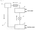
- Fig. 2 shows an embodiment of a refrigerant circulation route in the heat transfer device (turbo refrigerating machine in the following explanation).
- the turbo refrigerating machine 1' mainly consists of a compressor 2', a condenser 4', an expansion mechanism 5', and an evaporator 6'.
- the solid arrow in Fig. 2 shows the refrigerant circulation direction.
- the compressor 2' compresses a low-pressure gas refrigerant and discharges a high-pressure gas refrigerant.
- the refrigerant discharged from the compressor 2' is supplied to the condenser 4'.
- the condenser 4' condenses a high-pressure gas refrigerant and discharges a high-pressure liquid refrigerant.
- the refrigerant discharged from the condenser 4' passes through the expansion valve of the expansion mechanism 5' and becomes a refrigerant in the low-pressure gas-liquid mixing state.
- the refrigerant is then supplied to the evaporator 6'.
- the evaporator 6' allows the refrigerant in the low-pressure gas-liquid mixing state to evaporate and discharges a low-pressure gas refrigerant.
- the low-pressure gas refrigerant discharged from the evaporator 6' is supplied to the compressor 2'.
- cool wind formed of cool water that is obtained by the function of the evaporator 6' is used for cooling a large-scale space.
- the heat transfer device of the present invention comprises an oxygen adsorption device between the evaporator and the compressor present in the refrigerant circulation route.
- the oxygen adsorption device 7 is provided between the evaporator 6 and the compressor 2.
- the oxygen adsorption device 8 is provided between the evaporator 4 and the compressor 2.
- the low-pressure gas refrigerant is present between the evaporator and the compressor.
- oxygen can be removed from the gas refrigerant.
- an oxygen adsorption device 7' is provided between the evaporator 6' and the compressor 2'.
- valves are provided before and after the oxygen adsorption device, and the oxygen adsorption device is removably mounted on the circulation route so that an oxygen adsorption material that adsorbs oxygen in the oxygen adsorption device can be easily removed or exchanged.
- Both manual and electric valves can be used as long as the valves are provided in the circulation route in a manner such that the flow of the refrigerant against the oxygen adsorption device can be controlled.
- the inside of the oxygen adsorption device is filled with the oxygen adsorption material.
- Oxygen is selectively adsorbed (absorbed) and removed from the gas refrigerant when oxygen passes through the oxygen adsorption device together with the gas refrigerant.
- oxygen adsorption materials are not limited as long as materials can selectively adsorb oxygen, and examples thereof include metal oxide-based oxygen adsorption materials and organic-based (sugar-based) oxygen adsorption materials.
- Such oxygen adsorption materials can be used singly or as a mixture of two or more.
- Metal oxide-based oxygen adsorption materials are preferred because the oxygen adsorption speed is fast.
- the oxygen adsorption material can be any form as long as the material is permeable to the gas refrigerant.
- the form of the oxygen adsorption material examples include powders, pellets, etc. Films or filters in which the oxygen adsorption material is adhered or immersed can also be used. Because the present invention includes the oxygen adsorption device filled with such an oxygen adsorption material, the amount of oxygen in the circulation route can be maintained at 0.1 volume% or less. This can reduce decomposition over time caused by oxygen of the refrigerant containing at least one of HFOs, HCFOs, or HCOs.
- the metal oxide-based oxygen adsorption material is an adsorption material that adsorbs oxygen by oxidation reaction (heat generation).
- a metal (Fe and/or Ce) oxide-based oxygen adsorption material is preferably used to selectively adsorb oxygen.
- Various conventionally known metal oxide-based oxygen adsorption materials can be used.
- the organic-based (sugar-based) oxygen adsorption material is an adsorption material that removes oxygen from the gas refrigerant by oxidation reaction (CO 2 release).
- Various conventionally known organic-based (sugar-based) oxygen adsorption materials can be used.
- the oxygen adsorption device used in the present invention may be a dedicated member filled with the oxygen adsorption material.
- the oxygen adsorption device may also serve as a drying device (drier) that is provided in the refrigerant circulation route in a known heat transfer device.
- the drier can be used as a member for simultaneously removing water and oxygen entrapped in the gas refrigerant.
- the heat transfer device of the present invention uses a magnetic bearing, a ceramic bearing, or an air bearing as a bearing that supports the axis of a motor driving the compression part compressing the refrigerant in the compressor, it may be an oil-free heat transfer device in which the amount of the refrigerant oil to be used is limited to 5 parts by weight or less per 100 parts by weight of the refrigerant.
- the above bearing does not require refrigerant oil for improving the lubricity of the bearing in addition to the refrigerant, and the amount of the refrigerant oil can be substantially set to 0 parts by weight. However, considering oil (grease etc.) entrapped during the construction of the heat transfer device, the amount of the refrigerant oil is preferably 5 parts by weight or less.
- the heat transfer device comprises a circulation route enclosing a refrigerant containing at least one of hydrofluoroolefins (HFOs), hydrochlorofluoroolefins (HCFOs), or hydrochloroolefins (HCOs); and the device comprises an oxygen adsorption device in a region at a pressure of 1.0 MPa or less in the circulation route.
- HFOs hydrofluoroolefins
- HCFOs hydrochlorofluoroolefins
- HCOs hydrochloroolefins
- the heat transfer device is not limited except that the oxygen adsorption device is placed in the low-pressure region at a pressure of 1.0 MPa or less in the refrigerant circulation route.
- the other structures are the same as the heat transfer device of embodiment 1.
- the low-pressure region at a pressure of 1.0 MPa or less has an increased risk of absorbing outside air, as compared to another region (a region at a pressure exceeding 1.0 MPa), and oxygen may be easily entrapped in the circulation route. Accordingly, the oxygen adsorption device provided at such a low-pressure region can efficiently prevent the influence of oxygen entrapment.
- the maximum pressure in the entire refrigerant circulation is not limited, it is usually about 3.0 MPa.
- the heat transfer device includes an oxygen adsorption device in the refrigerant circulation route.
- the position of the oxygen adsorption device is not limited as long as it is in the low-pressure region at a pressure of 1.0 MPa or less; however, oxygen can be efficiently adsorbed in a place where the refrigerant and oxygen are present in a gas phase. Accordingly, as in the case of the heat transfer device of embodiment 1, the oxygen adsorption device is preferably positioned between the evaporator and compressor and in the low-pressure region at a pressure of 1.0 MPa or less.
- embodiment 2 also includes the oxygen adsorption device that is filled with the oxygen adsorption material, the amount of oxygen in the circulation route can be preferably maintained at 0.1 volume% or less, thus reducing decomposition over time caused by oxygen of a refrigerant containing at least one of HFOs, HCFOs, or HCOs.
- the heat transfer method of the present invention can be performed by circulating the refrigerant in the refrigerant circulation route of the heat transfer device according to the present invention. Specifically, the circulation of refrigerant is explained as above by referring to the examples of the air-conditioner ( Fig. 1 ) and the turbo refrigerating machine ( Fig. 2 ).
Landscapes
- Engineering & Computer Science (AREA)
- Chemical & Material Sciences (AREA)
- Thermal Sciences (AREA)
- Physics & Mathematics (AREA)
- Mechanical Engineering (AREA)
- Combustion & Propulsion (AREA)
- Materials Engineering (AREA)
- Organic Chemistry (AREA)
- Chemical Kinetics & Catalysis (AREA)
- General Engineering & Computer Science (AREA)
- Analytical Chemistry (AREA)
- Power Engineering (AREA)
- Lubricants (AREA)
- Structures Of Non-Positive Displacement Pumps (AREA)
- Other Air-Conditioning Systems (AREA)
- Organic Low-Molecular-Weight Compounds And Preparation Thereof (AREA)
Abstract
Description
- The present invention relates to a heat transfer device and a heat transfer method using the same.
- Hydrofluorocarbons (HFCs), such as HFC-125 and HFC-32, have been widely used as important substitutes for chlorofluorocarbons (CFCs), hydrochlorofluorocarbons (HCFCs), etc., which are known as substances that deplete the ozone layer. Known examples of such substitutes include "R-410A," which is a mixture of HFC-32 and HFC-125; "R-404A," which is a mixture of HFC-125, HFC-134a, and HFC-143a; etc.
- The above substitutes have various applications, such as heat transfer media, refrigerants, foaming agents, solvents, cleaning agents, propellants, and fire extinguishers, and are consumed in large amounts. However, since these substances have a global warming potential (GWP) several thousand times higher than that of CO2, many people are concerned that their diffusion may greatly affect global warming.
- As a global warming countermeasure, the substances are collected after being used; however, not all of them can be collected, and their diffusion due to leakage cannot be disregarded. For use in refrigerants or heat transfer media, although CO2 and hydrocarbon-based substances have been considered as substituents, CO2 refrigerants have many difficulties, such as insufficient refrigeration efficiency under a high-temperature atmosphere and the requirement of large equipment. Hydrocarbon-based substances also pose safety problems due to their high flammability.
- Hydrohaloolefins with a low GWP are recently attracting attention as substances that can solve these problems. Hydrohaloolefin is a generic name for unsaturated hydrocarbons containing hydrogen and halogen (e.g., fluorine and chlorine), and includes substances represented by the following chemical formulae. The description in parentheses following each chemical formula indicates the refrigerant number typically used in the field of refrigerants (including geometric isomers).
CF3CF=CF2 (HFO-1216yc),
CF3CF=CHF (HFO-1225ye),
CF3CF=CH2 (HFO-1234yf),
CF3CH=CHF (HFO-1234ze),
CF3CH=CH2 (HFO-1243zf)
CF3CCl=CH2 (HCFO-1233xf),
CF2ClCCl=CH2 (HCFO-1232xf),
CF3CH=CHCl (HCFO-1233zd),
CF3CCl=CHCl (HCFO-1223xd),
CClF2CCl=CHCl (HCFO-1222xd),
CFCl2CCl=CH2 (HCFO-1231xf),
and
CH2ClCCl=CCl2 (HCO-1230xa).
- Of these, fluoropropenes are particularly promising substances as candidates for low GWP refrigerants or heat transfer media; however, since fluoropropenes are gradually decomposed over time, they are not highly stable substances. Thus, when used in various applications, these substances have a problem of gradually reducing performance depending on the situation or environment. The performance is particularly reduced when air (oxygen) is entrapped in a refrigerant.
- In general, in mobile air conditioners or like devices to which a refrigerant is charged at the factory under construction management, there is little possibility of an air (oxygen) entrapment problem. However, stationary air conditioners or like devices are required to be charged with a refrigerant on site. The charging of the refrigerant relies on the contractor's management ability. Thus, entrapped air (oxygen) has been considered to be a primary cause of failures and problems, such as reduction of refrigeration capacity.
- A method for controlling the operation of a compressor system (turbo refrigerating machine) using conventional low-pressure refrigerant HCFC-123 has a risk of entrapping air from the outside into the refrigerant system because of the negative pressure in the system during operation. However, there may be the same risk even when hydrohaloolefin is used in place of HCFC.
- Additionally, by using a magnetic bearing, a ceramic bearing, or an air bearing as a bearing that supports the axis of a motor driving a compression part that compresses a refrigerant in a compressor, an oil-free device has been recently developed in which the amount of the refrigerant oil to be used is limited to 5 parts by weight or less per 100 parts by weight of the refrigerant. This device can reduce costs and maintenance load involving the exchange of refrigerant oil etc., and can prevent the refrigerant dissolved in the refrigerant oil from discharging into the atmosphere. However, although an influence caused by the refrigerant oil can be reduced, hydrohaloolefin may be gradually decomposed when air (oxygen) is entrapped in the refrigerant.
- In conventional HFC and HCFC refrigerants, simple replacement of such refrigerants can solve the problem. However, in hydrohaloolefin-containing refrigerants, oxidative degradation of the refrigerants may generate acid, which may corrode metal parts of the device, and thus necessitate equipment replacement.
- PTL 1: Pamphlet of
WO2008-27511 - An object of the present invention is to provide a heat transfer device in which a hydrohaloolefin-containing refrigerant is enclosed in a circulation route, the heat transfer device being capable of reducing the influence of oxygen entrapped in the circulation route; and a heat transfer method using the heat transfer device.
- As a result of extensive research to achieve the above object, the present inventors found that the above object can be achieved by a heat transfer device that includes an oxygen adsorption device at a specific region in a refrigerant circulation route. Based on this finding, the present invention was accomplished.
- Specifically, the present invention relates to the following heat transfer device and heat transfer method using the device.
- 1. A heat transfer device comprising a circulation route enclosing a refrigerant containing at least one member selected from the group consisting of hydrofluoroolefins (HFOs), hydrochlorofluoroolefins (HCFOs), and hydrochloroolefins (HCOs); and
the device comprising an oxygen adsorption device between an evaporator and a compressor present in the circulation route. - 2. A heat transfer device comprising a circulation route enclosing a refrigerant containing at least one member selected from the group consisting of hydrofluoroolefins (HFOs), hydrochlorofluoroolefins (HCFOs), and hydrochloroolefins (HCOs); and
the device comprising an oxygen adsorption device in a region at a pressure of 1.0 MPa or less in the circulation route. - 3. The heat transfer device according to
Item - 4. The heat transfer device according to any one of
Items 1 to 3, wherein the circulation route has an oxygen amount of 0.1 volume% or less. - 5. The heat transfer device according to any one of
Items 1 to 4, wherein the circulation route comprises refrigerant oil in addition to the refrigerant, and the refrigerant oil is contained in an amount of 5 parts by weight or less per 100 parts by weight of the refrigerant. - 6. The heat transfer device according to any one of
Items 1 to 5, comprising valves before and after the oxygen adsorption device in the circulation route. - 7. The heat transfer device according to
Item - 8. A heat transfer method comprising circulating the refrigerant in the circulation route of the heat transfer device according to
Item 1. - 9. A heat transfer method comprising circulating the refrigerant in the circulation route of the heat transfer device according to
Item 2. - In the heat transfer device and the heat transfer method using the device according to the present invention, since the heat transfer device comprises an oxygen adsorption device at a specific region in a refrigerant circulation route, oxygen that is entrapped in the circulation route can be removed by the oxygen adsorption device, thus reducing oxygen influence against the refrigerant.
-
-
Fig. 1 shows an embodiment of a refrigerant circulation route in the heat transfer device (in particular,Fig. 1 shows an air conditioner) according to the present invention. -
Fig. 2 shows an embodiment of a refrigerant circulation route in the heat transfer device (in particular,Fig. 2 shows a turbo refrigerating machine) according to the present invention. - The heat transfer device of the present invention comprises a circulation route enclosing a refrigerant containing at least one member selected from the group consisting of hydrofluoroolefins (HFOs), hydrochlorofluoroolefins (HCFOs), and hydrochloroolefins (HCOs) among hydrohaloolefins. The heat transfer device can be classified roughly into two groups, i.e.,
embodiment 1 andembodiment 2 described below. - A heat transfer device comprising a circulation route enclosing a refrigerant containing at least one member selected from the group consisting of hydrofluoroolefins (HFOs), hydrochlorofluoroolefins (HCFOs), and hydrochloroolefins (HCOs); and the device comprising an oxygen adsorption device between an evaporator and a compressor present in the circulation route.
- A heat transfer device comprising a circulation route enclosing a refrigerant containing at least one member selected from the group consisting of hydrofluoroolefins (HFOs), hydrochlorofluoroolefins (HCFOs), and hydrochloroolefins (HCOs); and the device comprising an oxygen adsorption device in a region at a pressure of 1.0 MPa or less in the circulation route.
- Embodiments 1 and 2 are separately explained below.
- The heat transfer device according to
embodiment 1 comprises a circulation route enclosing a refrigerant containing at least one member selected from the group consisting of hydrofluoroolefins (HFOs), hydrochlorofluoroolefins (HCFOs), and hydrochloroolefins (HCOs); and the device comprises an oxygen adsorption device between an evaporator and a compressor present in the circulation route. - The refrigerant is not limited as long as it comprises at least one member selected from the group consisting of HFOs, HCFOs, or HCOs. Examples of HFOs include 2,3,3,3-tetrafluoropropene (HFO-1234yf), 1,3,3,3-tetrafluoropropene (HFO-1234ze), 1,2,3,3-tetrafluoropropene (HFO-1234ye), 1,1,2,3-tetrafluoropropene (HFO-1234yc), 1,2,3,3,3-pentafluoropropene (HFO-1225ye), 1,1,3,3,3-pentafluoropropene (HFO-1225zc), 3,3,3-trifluoropropene (HFO-1243zf), 1,1,1,4,4,4-hexafluoro-2-butene (HFO-1336mzz), 1,1,1,2,4,4,5,5,5-nonafluoropentene (HFO-1429myz), etc.
- Examples of HCFOs include 2-chloro-3,3,3-trifluoropropene (HCFO-1233xf), 2,3-dichloro-3,3-difluoropropene (HCFO-1232xf), 1-chloro-3,3,3-trifluoropropene (HCFO-1233zd), 2-chloro-3,3,3-trifluoropropene (HCFO-1233xf), 2,3-dichloro-3,3-difluoropropene (HCFO-1232xf), 1,2-dichloro-3,3,3-trifluoropropene (HCFO-1223xd), 1,2,3-trichloro-3,3-difluoropropene (HCFO-1222xd), 2,3,3-trichloro-3-fluoropropene (HCFO-1231xf), etc.
- Examples of HCOs include 1,3,3,3-tetrachloropropene (HCO-1230zd), 1,1,2,3-tetrachloropropene (HCO-1230xa), 1,1,3,3-tetrachloropropene (HCO-1230za), 2,3,3,3-tetrachloropropene (HCO-1230xf), etc.
- These HFOs, HCFOs, and HCOs can be used singly or as a mixture of two or more. It is also possible to mix refrigerants other than HFOs, HCFOs, and HCOs. In this case, adjusting the total amount of HFOs, HCFOs, and HCOs in the refrigerant mixture to 50 wt% or more is preferable.
- Examples of other refrigerants include HFC-32, HFC-41, HFC-125, HFC-134, HFC-143, HFC-152, HFC-227, HFC-236, HFC-245, HFC-338, HFC-347, HFC-356, HFC-365, HFC-449, HFC-43-10, HFE-125, HFE-134, HFE-143, HFE-152, HFE-236, HFE-245, HFE-254, HFE-338, HFE-347, HFE-356, HFE-365, HFE-449, etc. When the above compounds have isomers, any isomers can be included. Examples further include hydrocarbons having a carbon number of 1 to 5 (for those having isomers, any isomers are included), CO2, etc. The refrigerant may comprise one or two or more of these other refrigerants.
- Examples of mixtures of other refrigerants and at least one member selected from the group consisting of HFOs, HCFOs, and HCOs include R-444A, R-444B, R-445A, R-446A, R-447A, R-448A, R-449A, R-449B, R-450A, R-451a, R-451B, R-452A, R-454A, R-454B, R-455A, R-513A, R-513B, etc.
- In the present invention, the refrigerant (or the refrigerant mixture) enclosed in the circulation route may consist of at least one member selected from the group consisting of HFOs, HCFOs, and HCOs.
- In the heat transfer device of the present invention, the refrigerant (hereinbelow a refrigerant mixture is also abbreviated as "refrigerant") comprising at least one of HFOs, HCFOs, or HCOs is enclosed in the refrigerant circulation route in the device, and heat is transferred by passing the refrigerant through each device disposed in the circulation route.
- The purpose of the heat transfer device is not limited. A wide variety of applications include heat transfer apparatuses, such as air conditioners (mobile air conditioners, domestic air conditioners, and air conditioners for business use), refrigerating machines, refrigerators, coolers (chillers), container refrigerating apparatuses, and hot-water supply systems. A specific example of the heat transfer device of the present invention is explained below with reference to the air conditioner (see
Fig. 1 ) or the turbo refrigerating machine (seeFig. 2 ), which is one of the vapor compression heat transfer devices. -
Fig. 1 shows an embodiment of the refrigerant circulation route in the heat transfer device (air conditioner in the following explanation) of the present invention. Theair conditioner 1 mainly consists of acompressor 2, a four-way switching valve 3, anoutdoor heat exchanger 4, anexpansion mechanism 5, and anindoor heat exchanger 6. InFig. 1 , the solid arrow indicates the refrigerant circulation direction during cooling while the dotted arrow indicates the refrigerant circulation direction during heating. The refrigerant circulation direction can be controlled by allowing the refrigerant discharged from thecompressor 2 to select theoutdoor heat exchanger 4 direction orindoor heat exchanger 6 direction using the operation of the four-way switching valve 3. - The refrigeration cycle of the
air conditioner 1 during cooling is explained. First, thecompressor 2 compresses a low-pressure gas refrigerant and discharges a high-pressure gas refrigerant. The refrigerant discharged from thecompressor 2 passes through the four-way switching valve 3 and is supplied to theoutdoor heat exchanger 4. Theoutdoor heat exchanger 4 condenses a high-pressure gas refrigerant and discharges a high-pressure liquid refrigerant. The refrigerant discharged from theoutdoor heat exchanger 4 passes through the expansion valve of theexpansion mechanism 5 and becomes a refrigerant in the low-pressure gas-liquid mixing state. The refrigerant is then supplied to theindoor heat exchanger 6. Theindoor heat exchanger 6 allows the refrigerant in the low-pressure gas-liquid mixing state to evaporate, and discharges a low-pressure gas refrigerant. The low-pressure gas refrigerant discharged from theindoor heat exchanger 6 is supplied to thecompressor 2. This refrigeration cycle can cool a room. - During cooling, the
outdoor heat exchanger 4 functions as a condenser and theindoor heat exchanger 6 functions as an evaporator. Specifically, evaporative latent heat of a refrigerant generated in theindoor heat exchanger 6 cools a room. On the other hand, during heating, by switching the four-way switching valve 3, theoutdoor heat exchanger 4 functions as an evaporator and theindoor heat exchanger 6 functions as a condenser. Specifically, condensed latent heat of a refrigerant generated in theindoor heat exchanger 4 heats a room. -
Fig. 2 shows an embodiment of a refrigerant circulation route in the heat transfer device (turbo refrigerating machine in the following explanation). The turbo refrigerating machine 1' mainly consists of a compressor 2', a condenser 4', an expansion mechanism 5', and an evaporator 6'. - The solid arrow in
Fig. 2 shows the refrigerant circulation direction. In this refrigeration cycle, the compressor 2' compresses a low-pressure gas refrigerant and discharges a high-pressure gas refrigerant. The refrigerant discharged from the compressor 2' is supplied to the condenser 4'. The condenser 4' condenses a high-pressure gas refrigerant and discharges a high-pressure liquid refrigerant. The refrigerant discharged from the condenser 4' passes through the expansion valve of the expansion mechanism 5' and becomes a refrigerant in the low-pressure gas-liquid mixing state. The refrigerant is then supplied to the evaporator 6'. The evaporator 6' allows the refrigerant in the low-pressure gas-liquid mixing state to evaporate and discharges a low-pressure gas refrigerant. The low-pressure gas refrigerant discharged from the evaporator 6' is supplied to the compressor 2'. In this refrigeration cycle, cool wind formed of cool water that is obtained by the function of the evaporator 6' is used for cooling a large-scale space. - The heat transfer device of the present invention comprises an oxygen adsorption device between the evaporator and the compressor present in the refrigerant circulation route. In
Fig. 1 , during cooling, since theoutdoor heat exchanger 4 functions as a condenser and theindoor heat exchanger 6 functions as an evaporator, theoxygen adsorption device 7 is provided between theevaporator 6 and thecompressor 2. In contrast, during heating, since theoutdoor heat exchanger 4 functions as an evaporator and theindoor heat exchanger 6 functions as a condenser, theoxygen adsorption device 8 is provided between theevaporator 4 and thecompressor 2. In either case of cooling or heating, the low-pressure gas refrigerant is present between the evaporator and the compressor. Thus, as the gas refrigerant passes through the oxygen adsorption device, oxygen can be removed from the gas refrigerant. InFig. 2 , an oxygen adsorption device 7' is provided between the evaporator 6' and the compressor 2'. - In the heat transfer device of the present invention, valves (not shown) are provided before and after the oxygen adsorption device, and the oxygen adsorption device is removably mounted on the circulation route so that an oxygen adsorption material that adsorbs oxygen in the oxygen adsorption device can be easily removed or exchanged. Both manual and electric valves can be used as long as the valves are provided in the circulation route in a manner such that the flow of the refrigerant against the oxygen adsorption device can be controlled.
- The inside of the oxygen adsorption device is filled with the oxygen adsorption material. Oxygen is selectively adsorbed (absorbed) and removed from the gas refrigerant when oxygen passes through the oxygen adsorption device together with the gas refrigerant. Such oxygen adsorption materials are not limited as long as materials can selectively adsorb oxygen, and examples thereof include metal oxide-based oxygen adsorption materials and organic-based (sugar-based) oxygen adsorption materials. Such oxygen adsorption materials can be used singly or as a mixture of two or more. Metal oxide-based oxygen adsorption materials are preferred because the oxygen adsorption speed is fast. The oxygen adsorption material can be any form as long as the material is permeable to the gas refrigerant. Examples of the form of the oxygen adsorption material include powders, pellets, etc. Films or filters in which the oxygen adsorption material is adhered or immersed can also be used. Because the present invention includes the oxygen adsorption device filled with such an oxygen adsorption material, the amount of oxygen in the circulation route can be maintained at 0.1 volume% or less. This can reduce decomposition over time caused by oxygen of the refrigerant containing at least one of HFOs, HCFOs, or HCOs.
- The metal oxide-based oxygen adsorption material is an adsorption material that adsorbs oxygen by oxidation reaction (heat generation). In the present invention, a metal (Fe and/or Ce) oxide-based oxygen adsorption material is preferably used to selectively adsorb oxygen. Various conventionally known metal oxide-based oxygen adsorption materials can be used.
- The organic-based (sugar-based) oxygen adsorption material is an adsorption material that removes oxygen from the gas refrigerant by oxidation reaction (CO2 release). Various conventionally known organic-based (sugar-based) oxygen adsorption materials can be used.
- The oxygen adsorption device used in the present invention may be a dedicated member filled with the oxygen adsorption material. The oxygen adsorption device may also serve as a drying device (drier) that is provided in the refrigerant circulation route in a known heat transfer device. In this case, by filling the drier with a drying material and an oxygen adsorption material, the drier can be used as a member for simultaneously removing water and oxygen entrapped in the gas refrigerant.
- As long as the heat transfer device of the present invention uses a magnetic bearing, a ceramic bearing, or an air bearing as a bearing that supports the axis of a motor driving the compression part compressing the refrigerant in the compressor, it may be an oil-free heat transfer device in which the amount of the refrigerant oil to be used is limited to 5 parts by weight or less per 100 parts by weight of the refrigerant. The above bearing does not require refrigerant oil for improving the lubricity of the bearing in addition to the refrigerant, and the amount of the refrigerant oil can be substantially set to 0 parts by weight. However, considering oil (grease etc.) entrapped during the construction of the heat transfer device, the amount of the refrigerant oil is preferably 5 parts by weight or less.
- The heat transfer device according to
embodiment 2 comprises a circulation route enclosing a refrigerant containing at least one of hydrofluoroolefins (HFOs), hydrochlorofluoroolefins (HCFOs), or hydrochloroolefins (HCOs); and the device comprises an oxygen adsorption device in a region at a pressure of 1.0 MPa or less in the circulation route. - In
embodiment 2, the heat transfer device is not limited except that the oxygen adsorption device is placed in the low-pressure region at a pressure of 1.0 MPa or less in the refrigerant circulation route. The other structures are the same as the heat transfer device ofembodiment 1. In the refrigerant circulation route, the low-pressure region at a pressure of 1.0 MPa or less has an increased risk of absorbing outside air, as compared to another region (a region at a pressure exceeding 1.0 MPa), and oxygen may be easily entrapped in the circulation route. Accordingly, the oxygen adsorption device provided at such a low-pressure region can efficiently prevent the influence of oxygen entrapment. Although the maximum pressure in the entire refrigerant circulation is not limited, it is usually about 3.0 MPa. - The heat transfer device according to
embodiment 2 includes an oxygen adsorption device in the refrigerant circulation route. The position of the oxygen adsorption device is not limited as long as it is in the low-pressure region at a pressure of 1.0 MPa or less; however, oxygen can be efficiently adsorbed in a place where the refrigerant and oxygen are present in a gas phase. Accordingly, as in the case of the heat transfer device ofembodiment 1, the oxygen adsorption device is preferably positioned between the evaporator and compressor and in the low-pressure region at a pressure of 1.0 MPa or less.
Sinceembodiment 2 also includes the oxygen adsorption device that is filled with the oxygen adsorption material, the amount of oxygen in the circulation route can be preferably maintained at 0.1 volume% or less, thus reducing decomposition over time caused by oxygen of a refrigerant containing at least one of HFOs, HCFOs, or HCOs. - The heat transfer method of the present invention can be performed by circulating the refrigerant in the refrigerant circulation route of the heat transfer device according to the present invention. Specifically, the circulation of refrigerant is explained as above by referring to the examples of the air-conditioner (
Fig. 1 ) and the turbo refrigerating machine (Fig. 2 ). -
- 1 Heat transfer device (Air conditioner in
Fig. 1 ) - 2 Compressor
- 3 Four-way switching valve
- 4 Outdoor heat exchanger (Condenser during cooling and evaporator during heating)
- 5 Expansion mechanism
- 6 Indoor heat exchanger (Evaporator during cooling and condenser during heating)
- 7 Oxygen adsorption device (during cooling)
- 8 Oxygen adsorption device (during heating)
- 1' Heat transfer device (Turbo refrigerating machine in
Fig. 2 ) - 2' Compressor
- 4' Condenser
- 5' Expansion mechanism
- 6' Evaporator
- 7' Oxygen adsorption device
Claims (9)
- A heat transfer device comprising a circulation route enclosing a refrigerant containing at least one member selected from the group consisting of hydrofluoroolefins (HFOs), hydrochlorofluoroolefins (HCFOs), and hydrochloroolefins (HCOs); and
the device comprising an oxygen adsorption device between an evaporator and a compressor present in the circulation route. - A heat transfer device comprising a circulation route enclosing a refrigerant containing at least one member selected from the group consisting of hydrofluoroolefins (HFOs), hydrochlorofluoroolefins (HCFOs), and hydrochloroolefins (HCOs); and
the device comprising an oxygen adsorption device in a region at a pressure of 1.0 MPa or less in the circulation route. - The heat transfer device according to claim 1 or 2, wherein the oxygen adsorption device comprises at least one of metal oxide-based oxygen adsorption materials or organic-based (sugar-based) oxygen adsorption materials.
- The heat transfer device according to any one of claims 1 to 3, wherein the circulation route has an oxygen amount of 0.1 volume% or less.
- The heat transfer device according to any one of claims 1 to 4, wherein the circulation route comprises refrigerant oil in addition to the refrigerant, and the refrigerant oil is contained in an amount of 5 parts by weight or less per 100 parts by weight of the refrigerant.
- The heat transfer device according to any one of claims 1 to 5, comprising valves before and after the oxygen adsorption device in the circulation route.
- The heat transfer device according to claim 5 or 6, wherein a bearing that supports an axis of a motor driving a compression part that compresses the refrigerant in the compressor present in the circulation route is a magnetic bearing, ceramic bearing, or air bearing.
- A heat transfer method comprising circulating the refrigerant in the circulation route of the heat transfer device according to claim 1.
- A heat transfer method comprising circulating the refrigerant in the circulation route of the heat transfer device according to claim 2.
Applications Claiming Priority (2)
| Application Number | Priority Date | Filing Date | Title |
|---|---|---|---|
| JP2016241257 | 2016-12-13 | ||
| PCT/JP2017/044207 WO2018110454A1 (en) | 2016-12-13 | 2017-12-08 | Heat transfer device and heat transfer method using same |
Publications (2)
| Publication Number | Publication Date |
|---|---|
| EP3557158A1 true EP3557158A1 (en) | 2019-10-23 |
| EP3557158A4 EP3557158A4 (en) | 2020-07-22 |
Family
ID=62559149
Family Applications (1)
| Application Number | Title | Priority Date | Filing Date |
|---|---|---|---|
| EP17882212.8A Ceased EP3557158A4 (en) | 2016-12-13 | 2017-12-08 | HEAT TRANSFER DEVICE AND HEAT TRANSFER METHOD THEREFOR |
Country Status (7)
| Country | Link |
|---|---|
| US (1) | US11377578B2 (en) |
| EP (1) | EP3557158A4 (en) |
| JP (2) | JP6766029B2 (en) |
| CN (1) | CN110073153A (en) |
| AU (1) | AU2017378601B2 (en) |
| CA (1) | CA3046290C (en) |
| WO (1) | WO2018110454A1 (en) |
Families Citing this family (5)
| Publication number | Priority date | Publication date | Assignee | Title |
|---|---|---|---|---|
| EP3789441A4 (en) | 2018-05-18 | 2021-07-07 | Osaka University | PROCESS FOR THE PRODUCTION OF TREATED SURFACE POLYMER, POLYMER, METALLIC POLYMER, BONDED LAMINATE AND THEIR PRODUCTION PROCESSES |
| JP7155804B2 (en) * | 2018-09-21 | 2022-10-19 | 株式会社富士通ゼネラル | Compressor and refrigeration cycle equipment |
| WO2020223196A1 (en) * | 2019-04-29 | 2020-11-05 | The Chemours Company Fc, Llc | Refrigerant blends in flooded systems |
| CN110440487B (en) * | 2019-07-29 | 2021-12-17 | 黄石东贝压缩机有限公司 | Method for removing residual air in refrigeration system |
| JP7116336B2 (en) * | 2020-11-10 | 2022-08-10 | ダイキン工業株式会社 | COMPOSITION CONTAINING A REFRIGERANT, USE THEREOF, AND REFRIGERATION HAVING THE SAME AND METHOD OF OPERATION OF THE REFRIGERATION MACHINE |
Family Cites Families (24)
| Publication number | Priority date | Publication date | Assignee | Title |
|---|---|---|---|---|
| JPS58213160A (en) * | 1982-06-04 | 1983-12-12 | 株式会社東芝 | Refrigeration cycle device |
| JP2822440B2 (en) | 1989-04-25 | 1998-11-11 | 三菱瓦斯化学株式会社 | Oxygen scavenger |
| KR930001255B1 (en) | 1989-04-25 | 1993-02-22 | 미쓰비시가스 가가꾸 가부시끼가이샤 | Deoxidation agent |
| JPH07269994A (en) * | 1994-03-31 | 1995-10-20 | Mitsubishi Gas Chem Co Inc | Cooling system |
| JP2004028359A (en) | 2002-06-21 | 2004-01-29 | Mitsubishi Electric Corp | Air conditioning / refrigeration equipment, heat source side unit, load side unit, compressor replacement method, heat exchanger expansion method |
| US20070033955A1 (en) * | 2003-07-10 | 2007-02-15 | Ran Luo | Electrically controlled defrost and expansion valve apparatus |
| JP2005257263A (en) | 2005-03-16 | 2005-09-22 | Sanyo Electric Co Ltd | Refrigeration equipment |
| JP2007315663A (en) | 2006-05-25 | 2007-12-06 | Sanden Corp | Refrigeration system |
| US8535555B2 (en) | 2006-09-01 | 2013-09-17 | E I Du Pont De Nemours And Company | Epoxide and fluorinated epoxide stabilizers for fluoroolefins |
| JP5535908B2 (en) | 2008-03-07 | 2014-07-02 | アーケマ・インコーポレイテッド | Halogenated alkene refrigerant compositions with improved oil return and methods using them |
| EP2312241B1 (en) * | 2008-06-24 | 2019-11-27 | Mitsubishi Electric Corporation | Refrigerating cycle apparatus, and air-conditioning apparatus |
| CN102574756B (en) | 2009-08-17 | 2014-09-17 | 阿科玛股份有限公司 | Azeotrope and azeotrope-like composition of 1-chloro-3,3,3-trifluoropropene and HFC-245eb |
| JP2011237146A (en) * | 2010-05-13 | 2011-11-24 | Panasonic Corp | Air conditioner |
| GB2508725B (en) | 2011-06-14 | 2016-06-15 | Mitsubishi Electric Corp | Air-conditioning apparatus |
| GB201122142D0 (en) | 2011-12-21 | 2012-02-01 | Venus Systems Ltd | Centrifugal compressors |
| US20140260252A1 (en) * | 2013-03-15 | 2014-09-18 | Honeywell International Inc. | Stabilized hfo and hcfo compositions for use in high temperature heat transfer applications |
| JP6017058B2 (en) * | 2013-10-24 | 2016-10-26 | 三菱電機株式会社 | Air conditioner |
| US10443912B2 (en) * | 2013-10-25 | 2019-10-15 | Mitsubishi Heavy Industries Thermal Systems, Ltd. | Refrigerant circulation device, method for circulating refrigerant and acid suppression method |
| JP5983671B2 (en) | 2014-03-31 | 2016-09-06 | ダイキン工業株式会社 | Azeotropic or azeotrope-like compositions containing 1-chloro-3,3,3-trifluoropropene and 1,1,1,3,3-pentafluoropropane |
| JP6487163B2 (en) * | 2014-07-31 | 2019-03-20 | 三菱重工サーマルシステムズ株式会社 | Turbo refrigerator |
| JP6456633B2 (en) * | 2014-09-05 | 2019-01-23 | 三菱重工サーマルシステムズ株式会社 | Turbo refrigerator |
| JP2016098280A (en) | 2014-11-19 | 2016-05-30 | 出光興産株式会社 | Lubricant composition for refrigerator and refrigerator |
| JP6642903B2 (en) * | 2015-03-31 | 2020-02-12 | 三菱重工サーマルシステムズ株式会社 | Refrigerant circulating device, refrigerant circulating method, refrigerant charging method, and operating method of refrigerant circulating device |
| WO2016189717A1 (en) * | 2015-05-28 | 2016-12-01 | ジョンソンコントロールズ ヒタチ エア コンディショニング テクノロジー (ホンコン) リミテッド | Refrigeration cycle device |
-
2017
- 2017-12-08 US US16/468,040 patent/US11377578B2/en active Active
- 2017-12-08 JP JP2017235784A patent/JP6766029B2/en active Active
- 2017-12-08 CA CA3046290A patent/CA3046290C/en active Active
- 2017-12-08 WO PCT/JP2017/044207 patent/WO2018110454A1/en not_active Ceased
- 2017-12-08 EP EP17882212.8A patent/EP3557158A4/en not_active Ceased
- 2017-12-08 CN CN201780077022.XA patent/CN110073153A/en active Pending
- 2017-12-08 AU AU2017378601A patent/AU2017378601B2/en active Active
-
2019
- 2019-08-01 JP JP2019142305A patent/JP7274971B2/en active Active
Also Published As
| Publication number | Publication date |
|---|---|
| WO2018110454A1 (en) | 2018-06-21 |
| CA3046290C (en) | 2021-05-11 |
| EP3557158A4 (en) | 2020-07-22 |
| AU2017378601A1 (en) | 2019-07-11 |
| JP2019184236A (en) | 2019-10-24 |
| AU2017378601B2 (en) | 2020-03-19 |
| JP7274971B2 (en) | 2023-05-17 |
| US20200017742A1 (en) | 2020-01-16 |
| US11377578B2 (en) | 2022-07-05 |
| JP2018096677A (en) | 2018-06-21 |
| CA3046290A1 (en) | 2018-06-21 |
| JP6766029B2 (en) | 2020-10-07 |
| CN110073153A (en) | 2019-07-30 |
Similar Documents
| Publication | Publication Date | Title |
|---|---|---|
| US11377578B2 (en) | Heat transfer device and heat transfer method using same | |
| JP6838100B2 (en) | Use of E-1,1,1,4,4,5-hexafluoro-2-butene in heat pumps | |
| US10335623B2 (en) | Non-flammable compositions of chloro-trifluoropropene | |
| US20180320942A1 (en) | Refrigeration cycle device and heat cycle system | |
| US9005468B2 (en) | Heat-transfer fluids and use thereof in countercurrent heat exchangers | |
| US20190233700A1 (en) | Heat‐transfer fluids and use thereof in countercurrent heat exchangers | |
| JP7060017B2 (en) | Working medium for thermal cycles, compositions for thermal cycle systems and thermal cycle systems | |
| JP2021517955A (en) | How to cool and / or heat an object or fluid in a car | |
| EP3026369B1 (en) | Refrigerant circulation device, method for circulating refrigerant and method for suppressing isomerization | |
| CN103025844A (en) | HFC composition | |
| WO2018021275A1 (en) | Working medium for heat cycles | |
| JP7081600B2 (en) | Azeotrope or azeotropic composition, working medium for thermal cycle and thermal cycle system | |
| US20220135504A1 (en) | Fluoroethylene composition | |
| EP3553416B1 (en) | Heat transport device and heat transport method using same |
Legal Events
| Date | Code | Title | Description |
|---|---|---|---|
| STAA | Information on the status of an ep patent application or granted ep patent |
Free format text: STATUS: THE INTERNATIONAL PUBLICATION HAS BEEN MADE |
|
| PUAI | Public reference made under article 153(3) epc to a published international application that has entered the european phase |
Free format text: ORIGINAL CODE: 0009012 |
|
| STAA | Information on the status of an ep patent application or granted ep patent |
Free format text: STATUS: REQUEST FOR EXAMINATION WAS MADE |
|
| 17P | Request for examination filed |
Effective date: 20190619 |
|
| AK | Designated contracting states |
Kind code of ref document: A1 Designated state(s): AL AT BE BG CH CY CZ DE DK EE ES FI FR GB GR HR HU IE IS IT LI LT LU LV MC MK MT NL NO PL PT RO RS SE SI SK SM TR |
|
| AX | Request for extension of the european patent |
Extension state: BA ME |
|
| DAV | Request for validation of the european patent (deleted) | ||
| DAX | Request for extension of the european patent (deleted) | ||
| A4 | Supplementary search report drawn up and despatched |
Effective date: 20200618 |
|
| RIC1 | Information provided on ipc code assigned before grant |
Ipc: F25B 1/00 20060101AFI20200612BHEP Ipc: F25B 43/00 20060101ALI20200612BHEP Ipc: C09K 5/04 20060101ALI20200612BHEP |
|
| STAA | Information on the status of an ep patent application or granted ep patent |
Free format text: STATUS: EXAMINATION IS IN PROGRESS |
|
| 17Q | First examination report despatched |
Effective date: 20220211 |
|
| RAP3 | Party data changed (applicant data changed or rights of an application transferred) |
Owner name: DAIKIN INDUSTRIES, LTD. |
|
| P01 | Opt-out of the competence of the unified patent court (upc) registered |
Effective date: 20230525 |
|
| REG | Reference to a national code |
Ref country code: DE Ref legal event code: R003 |
|
| STAA | Information on the status of an ep patent application or granted ep patent |
Free format text: STATUS: THE APPLICATION HAS BEEN REFUSED |
|
| 18R | Application refused |
Effective date: 20240104 |