EP3557149A1 - Outdoor unit for air conditioner - Google Patents
Outdoor unit for air conditioner Download PDFInfo
- Publication number
- EP3557149A1 EP3557149A1 EP16924136.1A EP16924136A EP3557149A1 EP 3557149 A1 EP3557149 A1 EP 3557149A1 EP 16924136 A EP16924136 A EP 16924136A EP 3557149 A1 EP3557149 A1 EP 3557149A1
- Authority
- EP
- European Patent Office
- Prior art keywords
- terminal block
- support element
- block support
- grounding plate
- outdoor unit
- Prior art date
- Legal status (The legal status is an assumption and is not a legal conclusion. Google has not performed a legal analysis and makes no representation as to the accuracy of the status listed.)
- Granted
Links
- 238000004378 air conditioning Methods 0.000 claims abstract description 41
- 238000005452 bending Methods 0.000 claims description 2
- 239000002184 metal Substances 0.000 description 12
- 239000000758 substrate Substances 0.000 description 11
- 239000003507 refrigerant Substances 0.000 description 9
- 229920003002 synthetic resin Polymers 0.000 description 8
- 239000000057 synthetic resin Substances 0.000 description 8
- 230000001681 protective effect Effects 0.000 description 7
- 229920005989 resin Polymers 0.000 description 6
- 239000011347 resin Substances 0.000 description 6
- 210000000078 claw Anatomy 0.000 description 4
- 230000003014 reinforcing effect Effects 0.000 description 4
- 230000005611 electricity Effects 0.000 description 3
- 238000004519 manufacturing process Methods 0.000 description 2
- 230000015572 biosynthetic process Effects 0.000 description 1
- 238000001816 cooling Methods 0.000 description 1
- 239000000428 dust Substances 0.000 description 1
- 230000000694 effects Effects 0.000 description 1
- 238000009434 installation Methods 0.000 description 1
- 238000000034 method Methods 0.000 description 1
- 230000002787 reinforcement Effects 0.000 description 1
- XLYOFNOQVPJJNP-UHFFFAOYSA-N water Substances O XLYOFNOQVPJJNP-UHFFFAOYSA-N 0.000 description 1
Images


Classifications
-
- F—MECHANICAL ENGINEERING; LIGHTING; HEATING; WEAPONS; BLASTING
- F24—HEATING; RANGES; VENTILATING
- F24F—AIR-CONDITIONING; AIR-HUMIDIFICATION; VENTILATION; USE OF AIR CURRENTS FOR SCREENING
- F24F1/00—Room units for air-conditioning, e.g. separate or self-contained units or units receiving primary air from a central station
- F24F1/06—Separate outdoor units, e.g. outdoor unit to be linked to a separate room comprising a compressor and a heat exchanger
- F24F1/20—Electric components for separate outdoor units
- F24F1/22—Arrangement or mounting thereof
-
- F—MECHANICAL ENGINEERING; LIGHTING; HEATING; WEAPONS; BLASTING
- F24—HEATING; RANGES; VENTILATING
- F24F—AIR-CONDITIONING; AIR-HUMIDIFICATION; VENTILATION; USE OF AIR CURRENTS FOR SCREENING
- F24F1/00—Room units for air-conditioning, e.g. separate or self-contained units or units receiving primary air from a central station
- F24F1/06—Separate outdoor units, e.g. outdoor unit to be linked to a separate room comprising a compressor and a heat exchanger
- F24F1/56—Casing or covers of separate outdoor units, e.g. fan guards
-
- F—MECHANICAL ENGINEERING; LIGHTING; HEATING; WEAPONS; BLASTING
- F24—HEATING; RANGES; VENTILATING
- F24F—AIR-CONDITIONING; AIR-HUMIDIFICATION; VENTILATION; USE OF AIR CURRENTS FOR SCREENING
- F24F11/00—Control or safety arrangements
- F24F11/89—Arrangement or mounting of control or safety devices
-
- F—MECHANICAL ENGINEERING; LIGHTING; HEATING; WEAPONS; BLASTING
- F24—HEATING; RANGES; VENTILATING
- F24F—AIR-CONDITIONING; AIR-HUMIDIFICATION; VENTILATION; USE OF AIR CURRENTS FOR SCREENING
- F24F13/00—Details common to, or for air-conditioning, air-humidification, ventilation or use of air currents for screening
- F24F13/20—Casings or covers
- F24F2013/207—Casings or covers with control knobs; Mounting controlling members or control units therein
Definitions
- the present invention relates to an outdoor unit of an air-conditioning apparatus provided with a sheet metal part for ground connection on a terminal block.
- an outdoor unit of an air-conditioning apparatus including a terminal block for connecting a wiring to a terminal of an electric component unit stored in a casing, and a terminal block support element made of a synthetic resin and configured to support the terminal block.
- Patent Literature 1 discloses a power line fixing device that fixes power lines of a power source and is provided in an electric component box made of a resin and used for the air-conditioning apparatus.
- This power line fixing device has a configuration in which a plurality of terminals as terminal blocks are arranged in parallel to one another on a surface of the electric component box made of a resin as a terminal block support element, and each of the plurality of terminals is individually screw-joined to the surface of the electric component box made of a resin.
- a reinforcement sheet metal is attached to a rear surface of the electric component box made of a resin to connect an electricity leakage shutdown device.
- Patent Literature 1 Japanese Unexamined Patent Application Publication No. Hei 7-280295
- the power line fixing device is provided with no unit for engaging and temporarily fixing the reinforcing plate, it is necessary to fix the reinforcing plate to the electric component box made of a resin with screw elements while holding the reinforcing plate by hands to prevent it from being moved, resulting in poor workability.
- the present invention has been made to solve the problems described above, and an object thereof is to provide an outdoor unit of an air-conditioning apparatus capable of improving the workability of an assembly work for attaching a terminal block and an earth grounding plate to a terminal block support element.
- An outdoor unit of an air-conditioning apparatus comprising: a casing that forms an outer shell; a terminal block disposed in the casing; a terminal block support element configured to support the terminal block; and an earth grounding plate sandwiched between the terminal block and the terminal block support element, wherein an engaging portion to be engaged with the terminal block support element is provided in the earth grounding plate, and a fixing element is provided to fasten the terminal block and the earth grounding plate engaged with the terminal block support element by the engaging portion together to the terminal block support element.
- the engaging portion to be engaged with the terminal block support element is formed in the earth grounding plate, and the fixing element is provided to fasten the terminal block and the earth grounding plate engaged with the terminal block support element together to the terminal block support element. Therefore, in the outdoor unit, during the assembling work for attaching the terminal block and the earth grounding plate to the terminal block support element, since the earth grounding plate is engaged with and temporarily fixed to the terminal block support element by the engaging portion so that the earth grounding plate is stably held, the terminal block and the earth grounding plate can be fastened together to the terminal block support element by a common fixing element, whereby man hours required for the assembling work can be reduced and the workability can be improved.
- Fig. 1 is a perspective view illustrating an outdoor unit of an air-conditioning apparatus according to an embodiment of the present invention.
- Fig. 2 is a perspective view illustrating an internal configuration of the outdoor unit of the air-conditioning apparatus according to the embodiment of the present invention. Note that front-and-back, lateral, and vertical directions described below are defined by directions illustrated in Fig. 1 .
- An outdoor unit 100 of an air-conditioning apparatus includes a casing 1 that forms an outer shell of the outdoor unit 100, as illustrated in Fig. 1 .
- the casing 1 includes a front-and-side panel 10, a right panel 11, a bottom panel 12, a top panel 13, and a rear panel 14.
- the front-and-side panel 10 forms a front face and a left side face of the casing 1, and has, for example, an L-shape in plan view.
- the front-and-side panel 10 of the casing 1 has a circular-shaped air outlet formed therein, and a fan guard 16 is attached to cover the air outlet.
- the outdoor unit 100 has a structure in which leg portions 15 are attached to a lower surface of the bottom panel 12 to be fixedly secured to an installation place.
- the casing 1 is defined by a separator 17 to be a fan compartment 2 in which heat is exchanged by a heat exchanger 20 and a propeller fan 21 and a machine compartment 3 in which refrigerant is compressed by a compressor 30.
- the heat exchanger 20, the propeller fan 21, a motor 22, and a motor mount 23 are disposed.
- the motor mount 23 is an element that holds the motor 22 to which the propeller fan 21 is attached.
- the motor mount 23 is disposed in front of the heat exchanger 20.
- the outdoor unit 100 is configured so that, when the propeller fan 21 rotates, air that has passed through the heat exchanger 20 flows into the outdoor unit 100, then passes through the propeller fan 21, and is discharged to the front of the outdoor unit 100.
- the outdoor unit 100 is configured so that, for example, during a cooling operation, the refrigerant in the heat exchanger 20 is cooled by air, and the air passing through the heat exchanger 20 is superheated by exchanging heat with the refrigerant.
- the compressor 30, a refrigerant pipe 31, an electric component unit 4, and a power supply unit 5 are disposed.
- the compressor 30 is mounted on a top surface of the bottom panel 12.
- the compressor 30 compresses the refrigerant supplied from an indoor unit.
- the refrigerant compressed by the compressor 30 is supplied to the heat exchanger 20 through the refrigerant pipe 31.
- the electric component unit 4 and the power supply unit 5 are disposed above the compressor 30 and the refrigerant pipe 31.
- Fig. 3 is an exploded perspective view illustrating a state in which the electric component unit of the outdoor unit of the air-conditioning apparatus according to the embodiment of the present invention.
- Fig. 4 is a partially enlarged perspective view illustrating the electric component unit of the outdoor unit of the air-conditioning apparatus according to the embodiment of the present invention and a state in which the power supply unit is attached to the right panel.
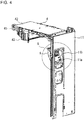
- Fig. 5 is an enlarged view of a portion A illustrated in Fig. 4 .
- the electric component unit 4 includes a control circuit substrate 40, a substrate fixing frame 41 made of a synthetic resin and fixes the control circuit substrate 40, and a substrate protective sheet metal 42 attached to the top surface of the substrate fixing frame 41 and protects the control circuit substrate 40.
- the electric component unit 4 supplies power to each component.
- a heat sink 43 that assists the exhaust heat is assembled to the bottom surface of the control circuit substrate 40.
- the heat sink 43 is fixed by a heat sink fixing sheet metal 45 attached to the substrate fixing frame 41 through an insulating protective element 44 made of a synthetic resin.
- the power supply unit 5 is attached to attaching portions 11b in a state of being inclined toward the inside of the casing 1, the attaching portions 11b protruding toward the inside of the casing 1 from an opening edge of an opening port 11a formed in the right panel 11.
- the power supply unit 5 is exposed to the outside through the opening port 11a formed in the right panel 11.
- the power supply unit 5 is covered by a protective cover 18 attached to the outer surface of the right panel 11, thereby to prevent dust or water from entering the opening port 11a.
- a terminal block support element 7, an earth grounding plate 8, a flange 71, a claw portion 71 a, a screw element 83, and a ground screw 84 as illustrated in Fig. 5 will be described later.
- Fig. 6 is a perspective view illustrating the power supply unit of the outdoor unit of the air-conditioning apparatus according to the embodiment of the present invention when viewed from the front.
- Fig. 7 is a perspective view illustrating the power supply unit of the outdoor unit of the air-conditioning apparatus according to the embodiment of the present invention when viewed from the rear.
- Fig. 8 is an exploded perspective view illustrating a state in which the power supply unit of the air-conditioning apparatus according to the embodiment of the present invention.
- Fig. 9 is a perspective view illustrating the terminal block of the outdoor unit of the air-conditioning apparatus according to the embodiment of the present invention.
- FIG. 10 is a perspective view illustrating the terminal block support element of the outdoor unit of the air-conditioning apparatus according to the embodiment of the present invention.
- Fig. 11 is a cross-sectional view taken along the line B-B illustrated in Fig. 10 .
- Fig. 12 is a perspective view illustrating the earth grounding plate of the outdoor unit of the air-conditioning apparatus according to the embodiment of the present invention.
- the power supply unit 5 includes a terminal block 6 disposed in the casing 1, the terminal block support element 7 configured to support the terminal block 6, the earth grounding plate 8 to be sandwiched between the terminal block 6 and the terminal block support element 7.
- the power supply unit 5 also includes a fixing element 9 serving as a screw element by which the terminal block 6 and the earth grounding plate 8 engaged with the terminal block support element 7 are fastened together to the terminal block support element 7.
- the electric power necessary for operation is supplied from the outside through the wiring attached to the outdoor unit 100.
- the wiring is used to supply the electric power for operating the indoor unit (not illustrated) of the air-conditioning apparatus and transmit the signal for controlling the indoor unit.
- the outdoor unit 100 has a configuration in which a plurality of wirings are drawn into the outdoor unit 100 to be connected to the terminal block 6 provided in the outdoor unit 100, thereby transmitting and receiving the electric power and the signal. Note that the terminal block 6 of the outdoor unit 100 is electrically connected to a terminal block of an indoor unit using a VVF cable.
- the terminal block 6 is made of a synthetic resin, and as illustrated in Fig. 8 and Fig. 9 , the terminal block 6 includes a plurality of internal wiring terminals 6a and a plurality of external wiring terminals 6b.
- the terminal block 6 serves as a connection intermediary between the external wiring and the internal wiring when being installed on site.
- Examples of the external wiring include a connection line with the indoor unit of the air-conditioning apparatus and a power supply line.
- the terminal block 6 is provided with rectangular protrusions 60, 60 extending outwardly from both left and right end faces of the terminal block 6.
- the protrusion 60 has a cutout 61 formed in the protrusion 60, the cutout having a size enabling an axial portion 90 of the fixing element 9 to pass therethrough.
- Fig. 9 illustrates a configuration in which the cutout 61 is formed in each of the left and right protrusions 60, but the cutout may be formed only in one of the left and right protrusions 60 through which the axial portion 90 of the fixing element 9 should pass.
- the terminal block support element 7 is made of a synthetic resin, and as illustrated in Fig. 4 and Fig. 5 , the terminal block support element 7 is attached to an inner surface of the right panel 11 to support the terminal block 6.
- the terminal block support element 7 includes a flat-shaped supporting portion 70 to which the terminal block 6 and the earth grounding plate 8 are attached, and flanges 71 protruding toward the right panel 11 from left and right edges of the supporting portion 70.
- One of the flanges 71 is screw-joined to the corresponding one of the attaching portions 11b provided at the opening edge of the opening port 11a in the right panel 11.
- the other flange 71 is provided with the claw portion 71a, and the claw portion 71a is inserted into a through hole formed in the other attaching portion 11b to be attached to the attaching portion 11b. That is, the power supply unit 5 is attached in an inclined manner to the inner surface of the right panel 11 by fixing the flanges 71 of the terminal block support element 7 to the attaching portions 11b provided at the opening edge of the opening port 11a in the right panel 11. Thus, the power supply unit 5 is inclined against the right panel 11, whereby the internal and external connection lines (not illustrated) can be connected to the terminal block 6 with good connection workability.
- a configuration in which the terminal block support element 7 is attached to the right panel 11 is not limited to the configuration illustrated in Fig. 10 , and other configurations may be adopted.
- a rectangular opening port 72 is formed in the supporting portion 70 of the terminal block support element 7.
- the power supply unit 5 is conveyed in a state in which, before the power supply unit 5 is attached to the right panel 11, an upper edge of the opening port 72 is placed on a hook 46 provided on a surface of the electric component unit 4 facing the inner surface of the right panel 11 so that the power supply unit 5 is temporarily fixed to the electric component unit 4.
- a protrusion inserting portion 73 into which one of the protrusions 60 of the terminal block 6 is to be inserted is formed in the terminal block support element 7.
- a stepped portion 70b protruding toward a side on which the terminal block 6 is attached is formed on a surface adjacent to the opening port 72 in the width direction (on a left side in Fig. 8 ).
- the protrusion inserting portion 73 communicating with the opening port 72 is formed in the stepped portion 70b and extends in the width direction of the supporting portion 70.
- the protrusion 60 inserted into the protrusion inserting portion 73 is placed on the stepped portion 70b, so that the terminal block 6 is positioned on the terminal block support element 7.
- the relationship between the protrusion 60 of the terminal block 6 and the protrusion inserting portion 73 of the terminal block support element 7 is not limited to the above-described configuration.
- a configuration may be adopted in which a protrusion or a recess is formed on the supporting portion 70 of the terminal block support element 7, and a recess or a protrusion is formed on the terminal block 6 to be fitted with the protrusion or the recess on the supporting portion 70.
- another configuration may be adopted as long as the supporting portion 70 of the terminal block support element 7 is fitted with the terminal block 6 and the terminal block 6 is positioned on the terminal block support element 7.
- a positioning recessed portion 70a is formed below the opening port 72, so that an upper edge and left and right side edges of the earth grounding plate 8 are fitted into the positioning recessed portion 70a. It is preferred that the groove depth of the recessed portion 70a be substantially the same as the thickness of the earth grounding plate 8 so that the earth grounding plate 8 can be fitted into the recessed portion 70a.
- one threaded hole 74 into which the axial portion 90 of the fixing element 9 is screwed is formed in the supporting portion 70 of the terminal block support element 7.
- the terminal block support element 7 may be formed of a sheet metal.
- the terminal block support element 7 is made of a synthetic resin, thereby improving the flexibility of formation of the opening port 72 and improving the workability when the power supply unit 5 is temporarily fixed to the electric component unit 4.
- the terminal block support element 7 may be formed of a sheet metal and the power supply unit 5 may be fixed to the electric component unit 4 without being temporarily fixed, but since the electric component unit 4 is provided in the upper portion in the casing 1, the size of the protective cover 18 is increased, thereby causing an increase in cost.
- the terminal block support element 7 be made of a synthetic metal in consideration of the workability and the manufacturing cost.
- the configuration is adopted in which the terminal block support element 7 made of a synthetic resin is combined with the earth grounding plate 8.
- the earth grounding plate 8 is made of a sheet metal, and for example, enables the connection line with the indoor unit of the air-conditioning apparatus and the power supply line to be connected to the earth ground.
- reference numeral 84 denotes a ground screw.
- an engaging portion 80 to be engaged with the terminal block support element 7 is formed in the earth grounding plate 8.
- the engaging portion 80 has a U-shaped clip structure in which a part of the edge of the earth grounding plate 8 is bent back toward the terminal block support element 7.
- the engaging portion 80 is formed in a U-shape at one end side of a lower edge of the earth grounding plate 8.
- the earth grounding plate 8 is engaged with the terminal block support element 7 by inserting the edge of the terminal block support element 7 into the U-shape of the engaging portion 80.
- the engaging portion 80 having a clip structure is not limited to the illustrated embodiment, provided that the earth grounding plate 8 can be engaged with the terminal block support element 7, and for example, the engaging portion 80 may be provided at a part of the upper edge.
- the shape of the engaging portion 80 of the earth grounding plate 8 is not limited to the U-shape illustrated in Fig. 12 .
- the engaging portion 80 may have a configuration in which for example, a protrusion or a recess is formed on a surface of the earth grounding plate 8, and a recess or a protrusion is formed on the supporting portion 70 of the terminal block support element 7 to be fitted with and engaged with the protrusion or the recess on the earth grounding plate 8.
- another configuration may be adopted providing that the engaging portion 80 enables the earth grounding plate 8 to be engaged with the terminal block support element 7.
- a through hole 81 through which the axial portion 90 of the fixing element 9 passes is formed at a position aligned with the cutout 61 formed in the protrusion 60 of the terminal block 6 and the threaded hole 74 formed in the terminal block support element 7.
- the earth grounding plate 8 has a bent surface portion 82 in which the lower end is bent toward the terminal block support element 7. Through holes 82a through which axial portions of the screw elements 83 pass are formed in the bent surface portion 82. As illustrated in Fig. 4 and Fig. 5 , the earth grounding plate 8 is fixed to the right panel 11 by the screw elements 83 having passed through the through holes 82a. Thus, a ground path can be secured by conducting electricity between the earth grounding plate 8 made of a sheet metal and the right panel 11 made of a sheet metal.
- the outdoor unit 100 even when electrical leakage occurs from the electric component unit 4, the electric current is passed from the earth grounding plate 8 through the ground line provided in the power supply line, thereby being capable of preventing damage on a human body due to electric shock even when a person touches the outdoor unit.
- the fixing element 9 includes one screw element by which the terminal block 6 and the earth grounding plate 8 engaged with the terminal block support element 7 by the engaging portion 80 are fastened together to the terminal block support element 7.
- the axial portion 90 passes through the cutout 61 of the terminal block 6, and passes through the through hole 81 of the earth grounding plate 8, and then a distal end of the axial portion 90 is screwed into the threaded hole 74 formed in the terminal block support element 7, so that the fixing element 9 is fastened.
- the terminal block 6 is conventionally fixed by two or more of fixing elements to prevent rotation.
- the protrusion 60 of the terminal block 6 is positioned by the protrusion inserting portion 73, whereby the rotation can be prevented by one fixing element 9.
- the engaging portion 80 to be engaged with the terminal block support element 7 is formed in the earth grounding plate 8, and the fixing element 9 is provided to fasten the terminal block 6 and the earth grounding plate 8 engaged with the terminal block support element 7 together to the terminal block support element 7.
- the earth grounding plate 8 since during the assembling work for attaching the terminal block 6 and the earth grounding plate 8 to the terminal block support element 7, the earth grounding plate 8 is engaged with and temporarily fixed to the terminal block support element 7 by the engaging portion 80 so that the earth grounding plate 8 is stably held, the terminal block 6 and the earth grounding plate 8 can be fastened together to the terminal block support element 7 by a common fixing element 9, whereby man hours required for the assembling work can be reduced and the workability can be improved.
- the manufacturing cost can be reduced.
- the outdoor unit 100 of the air-conditioning apparatus of the present embodiment has a configuration in which the earth grounding plate 8 is engaged with the terminal block support element 7 by inserting the edge of the terminal block support element 7 into the U-shape of the engaging portion 80 formed by bending back a part of the edge of the earth grounding plate 8. Accordingly, the earth grounding plate 8 having a very simple structure is easily formed, and the earth grounding plate 8 is securely engaged with and temporarily fixed to the terminal block support element 7.
- the terminal block 6 is provided with the protrusions 60 protruding toward the terminal block support element 7, and the protrusion inserting portion 73 into which the protrusion 60 is to be inserted is formed in the terminal block support element 7. Therefore, the terminal block 6 is temporarily fixed to the terminal block support element 7 so that the terminal block 6 is stably held, whereby the terminal block 6 and the earth grounding plate 8 can be fastened together to the terminal block support element 7, thereby improving the workability.
- the earth grounding plate 8 is fixed to the casing 1, a ground path can be secured conducting electricity between the earth grounding plate 8 and the casing 1. Accordingly, in the outdoor unit 100, even when electrical leakage occurs from the electric component unit 4, the electric current is passed from the earth grounding plate 8 through the ground line provided in the power supply line, thereby capable of preventing damage on a human body due to electric shock even when a person touches the outdoor unit.
Abstract
Description
- The present invention relates to an outdoor unit of an air-conditioning apparatus provided with a sheet metal part for ground connection on a terminal block.
- There has been conventionally known an outdoor unit of an air-conditioning apparatus including a terminal block for connecting a wiring to a terminal of an electric component unit stored in a casing, and a terminal block support element made of a synthetic resin and configured to support the terminal block.
- For example,
Patent Literature 1 discloses a power line fixing device that fixes power lines of a power source and is provided in an electric component box made of a resin and used for the air-conditioning apparatus. This power line fixing device has a configuration in which a plurality of terminals as terminal blocks are arranged in parallel to one another on a surface of the electric component box made of a resin as a terminal block support element, and each of the plurality of terminals is individually screw-joined to the surface of the electric component box made of a resin. A reinforcement sheet metal is attached to a rear surface of the electric component box made of a resin to connect an electricity leakage shutdown device. - Patent Literature 1: Japanese Unexamined Patent Application Publication No.
Hei 7-280295 - In the power line fixing device disclosed in
Patent Literature 1, a reinforcing plate and a plurality of terminal blocks are individually screw-joined to the electric component box made of a resin, resulting in an increase in the number of assembly processes. Therefore, in the power line fixing device, man hours are required for the assembling work, leading to poor workability. In this power line fixing device, a plurality of screw elements are required, resulting in an increase in number of elements, and screw holes into which the screw elements are screwed are required to be formed, resulting in an increase in cost. Furthermore, since the power line fixing device is provided with no unit for engaging and temporarily fixing the reinforcing plate, it is necessary to fix the reinforcing plate to the electric component box made of a resin with screw elements while holding the reinforcing plate by hands to prevent it from being moved, resulting in poor workability. - The present invention has been made to solve the problems described above, and an object thereof is to provide an outdoor unit of an air-conditioning apparatus capable of improving the workability of an assembly work for attaching a terminal block and an earth grounding plate to a terminal block support element. Solution to Problem
- An outdoor unit of an air-conditioning apparatus, comprising: a casing that forms an outer shell; a terminal block disposed in the casing; a terminal block support element configured to support the terminal block; and an earth grounding plate sandwiched between the terminal block and the terminal block support element, wherein an engaging portion to be engaged with the terminal block support element is provided in the earth grounding plate, and a fixing element is provided to fasten the terminal block and the earth grounding plate engaged with the terminal block support element by the engaging portion together to the terminal block support element.
- According to the outdoor unit of the air-conditioning apparatus of the embodiment of the present invention, the engaging portion to be engaged with the terminal block support element is formed in the earth grounding plate, and the fixing element is provided to fasten the terminal block and the earth grounding plate engaged with the terminal block support element together to the terminal block support element. Therefore, in the outdoor unit, during the assembling work for attaching the terminal block and the earth grounding plate to the terminal block support element, since the earth grounding plate is engaged with and temporarily fixed to the terminal block support element by the engaging portion so that the earth grounding plate is stably held, the terminal block and the earth grounding plate can be fastened together to the terminal block support element by a common fixing element, whereby man hours required for the assembling work can be reduced and the workability can be improved.
-
-
Fig. 1 is a perspective view illustrating an outdoor unit of an air-conditioning apparatus according to an embodiment of the present invention. -
Fig. 2 is a perspective view illustrating an internal configuration of the outdoor unit of the air-conditioning apparatus according to the embodiment of the present invention. -
Fig. 3 is an exploded perspective view illustrating a state in which an electric component unit of the outdoor unit of the air-conditioning apparatus according to the embodiment of the present invention. -
Fig. 4 is a partially enlarged perspective view illustrating the electric component unit of the outdoor unit of the air-conditioning apparatus according to the embodiment of the present invention and a state in which a power supply unit is attached to a right panel. -
Fig. 5 is an enlarged view of a portion A illustrated inFig. 4 . -
Fig. 6 is a perspective view illustrating the power supply unit of the outdoor unit of the air-conditioning apparatus according to the embodiment of the present invention when viewed from the front. -
Fig. 7 is a perspective view illustrating the power supply unit of the outdoor unit of the air-conditioning apparatus according to the embodiment of the present invention when viewed from the rear. -
Fig. 8 is an exploded perspective view illustrating a state in which the power supply unit of the air-conditioning apparatus according to the embodiment of the present invention. -
Fig. 9 is a perspective view illustrating a terminal block of the outdoor unit of the air-conditioning apparatus according to the embodiment of the present invention. -
Fig. 10 is a perspective view illustrating a terminal block support element of the outdoor unit of the air-conditioning apparatus according to the embodiment of the present invention. -
Fig. 11 is a cross-sectional view taken along the line B-B illustrated inFig. 10 . -
Fig. 12 is a perspective view illustrating an earth grounding plate of the outdoor unit of the air-conditioning apparatus according to the embodiment of the present invention. - Hereinafter, embodiments of the present invention will be described with reference to the drawings. In the drawings, identical or corresponding portions are denoted by the same reference numerals, and descriptions thereon will be appropriately omitted or simplified. Variations may be made as appropriate to the shapes, sizes, relative positions, and other specific details of individual features as illustrated in the drawings within the scope of the present invention.
-
Fig. 1 is a perspective view illustrating an outdoor unit of an air-conditioning apparatus according to an embodiment of the present invention.Fig. 2 is a perspective view illustrating an internal configuration of the outdoor unit of the air-conditioning apparatus according to the embodiment of the present invention. Note that front-and-back, lateral, and vertical directions described below are defined by directions illustrated inFig. 1 . - An
outdoor unit 100 of an air-conditioning apparatus according to the embodiment includes acasing 1 that forms an outer shell of theoutdoor unit 100, as illustrated inFig. 1 . By way of example, thecasing 1 includes a front-and-side panel 10, aright panel 11, abottom panel 12, atop panel 13, and arear panel 14. The front-and-side panel 10 forms a front face and a left side face of thecasing 1, and has, for example, an L-shape in plan view. The front-and-side panel 10 of thecasing 1 has a circular-shaped air outlet formed therein, and afan guard 16 is attached to cover the air outlet. Theoutdoor unit 100 has a structure in whichleg portions 15 are attached to a lower surface of thebottom panel 12 to be fixedly secured to an installation place. - As illustrated in
Fig. 2 , thecasing 1 is defined by aseparator 17 to be afan compartment 2 in which heat is exchanged by aheat exchanger 20 and apropeller fan 21 and amachine compartment 3 in which refrigerant is compressed by acompressor 30. - In the
fan compartment 2, theheat exchanger 20, thepropeller fan 21, amotor 22, and amotor mount 23 are disposed. Themotor mount 23 is an element that holds themotor 22 to which thepropeller fan 21 is attached. Themotor mount 23 is disposed in front of theheat exchanger 20. Theoutdoor unit 100 is configured so that, when thepropeller fan 21 rotates, air that has passed through theheat exchanger 20 flows into theoutdoor unit 100, then passes through thepropeller fan 21, and is discharged to the front of theoutdoor unit 100. Thus, theoutdoor unit 100 is configured so that, for example, during a cooling operation, the refrigerant in theheat exchanger 20 is cooled by air, and the air passing through theheat exchanger 20 is superheated by exchanging heat with the refrigerant. - In the
machine compartment 3, thecompressor 30, arefrigerant pipe 31, anelectric component unit 4, and apower supply unit 5 are disposed. Thecompressor 30 is mounted on a top surface of thebottom panel 12. Thecompressor 30 compresses the refrigerant supplied from an indoor unit. The refrigerant compressed by thecompressor 30 is supplied to theheat exchanger 20 through therefrigerant pipe 31. Theelectric component unit 4 and thepower supply unit 5 are disposed above thecompressor 30 and therefrigerant pipe 31. -
Fig. 3 is an exploded perspective view illustrating a state in which the electric component unit of the outdoor unit of the air-conditioning apparatus according to the embodiment of the present invention.Fig. 4 is a partially enlarged perspective view illustrating the electric component unit of the outdoor unit of the air-conditioning apparatus according to the embodiment of the present invention and a state in which the power supply unit is attached to the right panel.Fig. 5 is an enlarged view of a portion A illustrated inFig. 4 . As illustrated inFig. 3 , theelectric component unit 4 includes acontrol circuit substrate 40, asubstrate fixing frame 41 made of a synthetic resin and fixes thecontrol circuit substrate 40, and a substrateprotective sheet metal 42 attached to the top surface of thesubstrate fixing frame 41 and protects thecontrol circuit substrate 40. Theelectric component unit 4 supplies power to each component. Aheat sink 43 that assists the exhaust heat is assembled to the bottom surface of thecontrol circuit substrate 40. Theheat sink 43 is fixed by a heat sinkfixing sheet metal 45 attached to thesubstrate fixing frame 41 through an insulatingprotective element 44 made of a synthetic resin. - As illustrated in
Fig. 4 andFig. 5 , thepower supply unit 5 is attached to attachingportions 11b in a state of being inclined toward the inside of thecasing 1, the attachingportions 11b protruding toward the inside of thecasing 1 from an opening edge of anopening port 11a formed in theright panel 11. Thepower supply unit 5 is exposed to the outside through theopening port 11a formed in theright panel 11. In the normal state, as illustrated inFig. 1 , thepower supply unit 5 is covered by aprotective cover 18 attached to the outer surface of theright panel 11, thereby to prevent dust or water from entering theopening port 11a. Note that a terminalblock support element 7, anearth grounding plate 8, aflange 71, aclaw portion 71 a, ascrew element 83, and aground screw 84 as illustrated inFig. 5 will be described later. - A configuration of the
power supply unit 5 will be described in detail with reference toFig. 6 to Fig. 12 .Fig. 6 is a perspective view illustrating the power supply unit of the outdoor unit of the air-conditioning apparatus according to the embodiment of the present invention when viewed from the front.Fig. 7 is a perspective view illustrating the power supply unit of the outdoor unit of the air-conditioning apparatus according to the embodiment of the present invention when viewed from the rear.Fig. 8 is an exploded perspective view illustrating a state in which the power supply unit of the air-conditioning apparatus according to the embodiment of the present invention.Fig. 9 is a perspective view illustrating the terminal block of the outdoor unit of the air-conditioning apparatus according to the embodiment of the present invention.Fig. 10 is a perspective view illustrating the terminal block support element of the outdoor unit of the air-conditioning apparatus according to the embodiment of the present invention.Fig. 11 is a cross-sectional view taken along the line B-B illustrated inFig. 10 .Fig. 12 is a perspective view illustrating the earth grounding plate of the outdoor unit of the air-conditioning apparatus according to the embodiment of the present invention. - As illustrated in
Fig. 6 to Fig. 8 , thepower supply unit 5 includes aterminal block 6 disposed in thecasing 1, the terminalblock support element 7 configured to support theterminal block 6, theearth grounding plate 8 to be sandwiched between theterminal block 6 and the terminalblock support element 7. Thepower supply unit 5 also includes a fixingelement 9 serving as a screw element by which theterminal block 6 and theearth grounding plate 8 engaged with the terminalblock support element 7 are fastened together to the terminalblock support element 7. - In the
outdoor unit 100, the electric power necessary for operation is supplied from the outside through the wiring attached to theoutdoor unit 100. In theoutdoor unit 100, the wiring is used to supply the electric power for operating the indoor unit (not illustrated) of the air-conditioning apparatus and transmit the signal for controlling the indoor unit. Theoutdoor unit 100 has a configuration in which a plurality of wirings are drawn into theoutdoor unit 100 to be connected to theterminal block 6 provided in theoutdoor unit 100, thereby transmitting and receiving the electric power and the signal. Note that theterminal block 6 of theoutdoor unit 100 is electrically connected to a terminal block of an indoor unit using a VVF cable. - The
terminal block 6 is made of a synthetic resin, and as illustrated inFig. 8 and Fig. 9 , theterminal block 6 includes a plurality ofinternal wiring terminals 6a and a plurality ofexternal wiring terminals 6b. Theterminal block 6 serves as a connection intermediary between the external wiring and the internal wiring when being installed on site. Examples of the external wiring include a connection line with the indoor unit of the air-conditioning apparatus and a power supply line. - As illustrated in
Fig. 9 , theterminal block 6 is provided withrectangular protrusions terminal block 6. Theprotrusion 60 has acutout 61 formed in theprotrusion 60, the cutout having a size enabling anaxial portion 90 of the fixingelement 9 to pass therethrough. Note thatFig. 9 illustrates a configuration in which thecutout 61 is formed in each of the left andright protrusions 60, but the cutout may be formed only in one of the left andright protrusions 60 through which theaxial portion 90 of the fixingelement 9 should pass. - The terminal
block support element 7 is made of a synthetic resin, and as illustrated inFig. 4 andFig. 5 , the terminalblock support element 7 is attached to an inner surface of theright panel 11 to support theterminal block 6. As illustrated inFig. 10 , the terminalblock support element 7 includes a flat-shaped supportingportion 70 to which theterminal block 6 and theearth grounding plate 8 are attached, andflanges 71 protruding toward theright panel 11 from left and right edges of the supportingportion 70. One of theflanges 71 is screw-joined to the corresponding one of the attachingportions 11b provided at the opening edge of theopening port 11a in theright panel 11. Theother flange 71 is provided with theclaw portion 71a, and theclaw portion 71a is inserted into a through hole formed in the other attachingportion 11b to be attached to the attachingportion 11b. That is, thepower supply unit 5 is attached in an inclined manner to the inner surface of theright panel 11 by fixing theflanges 71 of the terminalblock support element 7 to the attachingportions 11b provided at the opening edge of theopening port 11a in theright panel 11. Thus, thepower supply unit 5 is inclined against theright panel 11, whereby the internal and external connection lines (not illustrated) can be connected to theterminal block 6 with good connection workability. Note that a configuration in which the terminalblock support element 7 is attached to theright panel 11 is not limited to the configuration illustrated inFig. 10 , and other configurations may be adopted. - As illustrated in
Fig. 10 , arectangular opening port 72 is formed in the supportingportion 70 of the terminalblock support element 7. Although not illustrated in detail, thepower supply unit 5 is conveyed in a state in which, before thepower supply unit 5 is attached to theright panel 11, an upper edge of theopening port 72 is placed on ahook 46 provided on a surface of theelectric component unit 4 facing the inner surface of theright panel 11 so that thepower supply unit 5 is temporarily fixed to theelectric component unit 4. - As illustrated in
Fig. 7 ,Fig. 8 , andFig. 10 , aprotrusion inserting portion 73 into which one of theprotrusions 60 of theterminal block 6 is to be inserted is formed in the terminalblock support element 7. Specifically, in the supportingportion 70, a steppedportion 70b protruding toward a side on which theterminal block 6 is attached is formed on a surface adjacent to theopening port 72 in the width direction (on a left side inFig. 8 ). Theprotrusion inserting portion 73 communicating with the openingport 72 is formed in the steppedportion 70b and extends in the width direction of the supportingportion 70. As illustrated inFig. 6 to Fig. 8 , theprotrusion 60 inserted into theprotrusion inserting portion 73 is placed on the steppedportion 70b, so that theterminal block 6 is positioned on the terminalblock support element 7. - Note that the relationship between the
protrusion 60 of theterminal block 6 and theprotrusion inserting portion 73 of the terminalblock support element 7 is not limited to the above-described configuration. Although not illustrated in detail, for example, a configuration may be adopted in which a protrusion or a recess is formed on the supportingportion 70 of the terminalblock support element 7, and a recess or a protrusion is formed on theterminal block 6 to be fitted with the protrusion or the recess on the supportingportion 70. Briefly, another configuration may be adopted as long as the supportingportion 70 of the terminalblock support element 7 is fitted with theterminal block 6 and theterminal block 6 is positioned on the terminalblock support element 7. - As illustrated in
Fig. 8 ,Fig. 10, and Fig. 11 , in the supportingportion 70 of the terminalblock support element 7, a positioning recessedportion 70a is formed below the openingport 72, so that an upper edge and left and right side edges of theearth grounding plate 8 are fitted into the positioning recessedportion 70a. It is preferred that the groove depth of the recessedportion 70a be substantially the same as the thickness of theearth grounding plate 8 so that theearth grounding plate 8 can be fitted into the recessedportion 70a. - As illustrated in
Fig. 8 andFig. 10 , one threadedhole 74 into which theaxial portion 90 of the fixingelement 9 is screwed is formed in the supportingportion 70 of the terminalblock support element 7. - Note that, although an explanation was made above on the assumption that the terminal
block support element 7 is made of a synthetic resin, the terminalblock support element 7 may be formed of a sheet metal. In theoutdoor unit 100, the terminalblock support element 7 is made of a synthetic resin, thereby improving the flexibility of formation of theopening port 72 and improving the workability when thepower supply unit 5 is temporarily fixed to theelectric component unit 4. In theoutdoor unit 100, the terminalblock support element 7 may be formed of a sheet metal and thepower supply unit 5 may be fixed to theelectric component unit 4 without being temporarily fixed, but since theelectric component unit 4 is provided in the upper portion in thecasing 1, the size of theprotective cover 18 is increased, thereby causing an increase in cost. Accordingly, it is preferred that the terminalblock support element 7 be made of a synthetic metal in consideration of the workability and the manufacturing cost. For the above reasons, in theoutdoor unit 100 of the air-conditioning apparatus of the present embodiment, the configuration is adopted in which the terminalblock support element 7 made of a synthetic resin is combined with theearth grounding plate 8. - As illustrated in
Fig. 6 and Fig. 7 , theearth grounding plate 8 is made of a sheet metal, and for example, enables the connection line with the indoor unit of the air-conditioning apparatus and the power supply line to be connected to the earth ground. Incidentally,reference numeral 84 denotes a ground screw. As illustrated inFig. 12 , an engagingportion 80 to be engaged with the terminalblock support element 7 is formed in theearth grounding plate 8. The engagingportion 80 has a U-shaped clip structure in which a part of the edge of theearth grounding plate 8 is bent back toward the terminalblock support element 7. In the example illustrated inFig. 12 , the engagingportion 80 is formed in a U-shape at one end side of a lower edge of theearth grounding plate 8. That is, theearth grounding plate 8 is engaged with the terminalblock support element 7 by inserting the edge of the terminalblock support element 7 into the U-shape of the engagingportion 80. Note that the engagingportion 80 having a clip structure is not limited to the illustrated embodiment, provided that theearth grounding plate 8 can be engaged with the terminalblock support element 7, and for example, the engagingportion 80 may be provided at a part of the upper edge. - The shape of the engaging
portion 80 of theearth grounding plate 8 is not limited to the U-shape illustrated inFig. 12 . Although not illustrated in detail, the engagingportion 80 may have a configuration in which for example, a protrusion or a recess is formed on a surface of theearth grounding plate 8, and a recess or a protrusion is formed on the supportingportion 70 of the terminalblock support element 7 to be fitted with and engaged with the protrusion or the recess on theearth grounding plate 8. Briefly, another configuration may be adopted providing that the engagingportion 80 enables theearth grounding plate 8 to be engaged with the terminalblock support element 7. - As illustrated in
Fig. 12 , in theearth grounding plate 8, a throughhole 81 through which theaxial portion 90 of the fixingelement 9 passes is formed at a position aligned with thecutout 61 formed in theprotrusion 60 of theterminal block 6 and the threadedhole 74 formed in the terminalblock support element 7. - The
earth grounding plate 8 has abent surface portion 82 in which the lower end is bent toward the terminalblock support element 7. Throughholes 82a through which axial portions of thescrew elements 83 pass are formed in thebent surface portion 82. As illustrated inFig. 4 andFig. 5 , theearth grounding plate 8 is fixed to theright panel 11 by thescrew elements 83 having passed through the throughholes 82a. Thus, a ground path can be secured by conducting electricity between theearth grounding plate 8 made of a sheet metal and theright panel 11 made of a sheet metal. Accordingly, in theoutdoor unit 100 according to the present embodiment, even when electrical leakage occurs from theelectric component unit 4, the electric current is passed from theearth grounding plate 8 through the ground line provided in the power supply line, thereby being capable of preventing damage on a human body due to electric shock even when a person touches the outdoor unit. - As illustrated in
Fig. 6 andFig. 8 , the fixingelement 9 includes one screw element by which theterminal block 6 and theearth grounding plate 8 engaged with the terminalblock support element 7 by the engagingportion 80 are fastened together to the terminalblock support element 7. Theaxial portion 90 passes through thecutout 61 of theterminal block 6, and passes through the throughhole 81 of theearth grounding plate 8, and then a distal end of theaxial portion 90 is screwed into the threadedhole 74 formed in the terminalblock support element 7, so that the fixingelement 9 is fastened. Note that theterminal block 6 is conventionally fixed by two or more of fixing elements to prevent rotation. However, in theoutdoor unit 100 of the air-conditioning apparatus of the present embodiment, theprotrusion 60 of theterminal block 6 is positioned by theprotrusion inserting portion 73, whereby the rotation can be prevented by one fixingelement 9. - In the
outdoor unit 100 of the air-conditioning apparatus of the present embodiment, the engagingportion 80 to be engaged with the terminalblock support element 7 is formed in theearth grounding plate 8, and the fixingelement 9 is provided to fasten theterminal block 6 and theearth grounding plate 8 engaged with the terminalblock support element 7 together to the terminalblock support element 7. Therefore, in theoutdoor unit 100, since during the assembling work for attaching theterminal block 6 and theearth grounding plate 8 to the terminalblock support element 7, theearth grounding plate 8 is engaged with and temporarily fixed to the terminalblock support element 7 by the engagingportion 80 so that theearth grounding plate 8 is stably held, theterminal block 6 and theearth grounding plate 8 can be fastened together to the terminalblock support element 7 by acommon fixing element 9, whereby man hours required for the assembling work can be reduced and the workability can be improved. - Furthermore, in the
outdoor unit 100, since theterminal block 6 and theearth grounding plate 8 are fastened together to the terminalblock support element 7 by thecommon fixing element 9, the number of elements can be reduced, and in theterminal block 6, the terminalblock support element 7 and theearth grounding plate 8, a plurality of through holes do not have to be formed through which theaxial portion 90 of the fixingelement 9 passes. Therefore, in theoutdoor unit 100, the manufacturing cost can be reduced. - The
outdoor unit 100 of the air-conditioning apparatus of the present embodiment has a configuration in which theearth grounding plate 8 is engaged with the terminalblock support element 7 by inserting the edge of the terminalblock support element 7 into the U-shape of the engagingportion 80 formed by bending back a part of the edge of theearth grounding plate 8. Accordingly, theearth grounding plate 8 having a very simple structure is easily formed, and theearth grounding plate 8 is securely engaged with and temporarily fixed to the terminalblock support element 7. - In the
outdoor unit 100 of the air-conditioning apparatus of the present embodiment, theterminal block 6 is provided with theprotrusions 60 protruding toward the terminalblock support element 7, and theprotrusion inserting portion 73 into which theprotrusion 60 is to be inserted is formed in the terminalblock support element 7. Therefore, theterminal block 6 is temporarily fixed to the terminalblock support element 7 so that theterminal block 6 is stably held, whereby theterminal block 6 and theearth grounding plate 8 can be fastened together to the terminalblock support element 7, thereby improving the workability. - In the
outdoor unit 100 of the air-conditioning apparatus of the present embodiment, since theearth grounding plate 8 is fixed to thecasing 1, a ground path can be secured conducting electricity between theearth grounding plate 8 and thecasing 1. Accordingly, in theoutdoor unit 100, even when electrical leakage occurs from theelectric component unit 4, the electric current is passed from theearth grounding plate 8 through the ground line provided in the power supply line, thereby capable of preventing damage on a human body due to electric shock even when a person touches the outdoor unit. - 1
Casing 2Fan compartment 3Machine compartment 4Electric component unit 5Power supply unit 6Terminal block 6aInternal wiring terminal 6bExternal wiring terminal 7 Terminalblock support element 8Earth grounding plate 9Fixing element 10 Front-and-side panel 11Right panel 11a Opening11b Attaching portion 12Bottom panel 13Top panel 14Rear panel 15Leg portion 16Fan guard 17Separator 18 Protective cover 20Heat exchanger 21Propeller fan 22Motor 23 Motor mount 30Compressor 31Refrigerant pipe 40Control circuit substrate 41Substrate fixing frame 42 Substrateprotective sheet metal 43Heat sink 44 Insulatingprotective element 45 Heat sink fixingsheet metal 46Hook 60Protrusion 61Cutout 70Supporting portion 70a Recessedportion 70b Steppedportion 71Flange 71a Claw portion 72Opening 73Protrusion inserting portion 74 Threadedhole 80Engaging portion 81 Throughhole 82Bent surface portion 82a Throughhole 83Screw element 84Ground screw 90Axial portion 100 Outdoor unit
Claims (4)
- An outdoor unit of an air-conditioning apparatus, comprising:a casing that forms an outer shell;a terminal block disposed in the casing;a terminal block support element configured to support the terminal block; andan earth grounding plate sandwiched between the terminal block and the terminal block support element,wherein an engaging portion to be engaged with the terminal block support element is provided in the earth grounding plate, anda fixing element is provided to fasten the terminal block and the earth grounding plate engaged with the terminal block support element by the engaging portion together to the terminal block support element.
- The outdoor unit of an air-conditioning apparatus of claim 1, wherein
the engaging portion has a U-shape formed by bending back a part of an edge of the earth grounding plate, and
the earth grounding plate is engaged with the terminal block support element by inserting the edge of the terminal block support element into the U-shape of the engaging portion. - The outdoor unit of an air-conditioning apparatus of claim 1 or 2, wherein
a protrusion protruding toward the terminal block support element is provided in the terminal block, and
a protrusion inserting portion into which the protrusion is to be inserted is formed in the terminal block support element. - The outdoor unit of an air-conditioning apparatus of any one of claims 1 to 3, wherein
the earth grounding plate is fixed to the casing by a screw element.
Applications Claiming Priority (1)
| Application Number | Priority Date | Filing Date | Title |
|---|---|---|---|
| PCT/JP2016/087592 WO2018109932A1 (en) | 2016-12-16 | 2016-12-16 | Outdoor unit for air conditioner |
Publications (3)
| Publication Number | Publication Date |
|---|---|
| EP3557149A1 true EP3557149A1 (en) | 2019-10-23 |
| EP3557149A4 EP3557149A4 (en) | 2019-12-25 |
| EP3557149B1 EP3557149B1 (en) | 2021-01-20 |
Family
ID=62558204
Family Applications (1)
| Application Number | Title | Priority Date | Filing Date |
|---|---|---|---|
| EP16924136.1A Active EP3557149B1 (en) | 2016-12-16 | 2016-12-16 | Outdoor unit for air conditioner |
Country Status (5)
| Country | Link |
|---|---|
| US (1) | US10852012B2 (en) |
| EP (1) | EP3557149B1 (en) |
| JP (1) | JP6628904B2 (en) |
| CN (1) | CN110062865B (en) |
| WO (1) | WO2018109932A1 (en) |
Families Citing this family (5)
| Publication number | Priority date | Publication date | Assignee | Title |
|---|---|---|---|---|
| CN109564013B (en) * | 2016-07-25 | 2021-09-03 | 三菱电机株式会社 | Outdoor unit of air conditioner |
| US20210033291A1 (en) * | 2018-01-26 | 2021-02-04 | Fujitsu General Limited | Electrical component module |
| EP3786538B1 (en) * | 2018-04-25 | 2024-01-10 | Mitsubishi Electric Corporation | Air conditioner outdoor unit |
| WO2021199155A1 (en) * | 2020-03-30 | 2021-10-07 | 三菱電機株式会社 | Outdoor unit for air conditioning device |
| JP7412602B2 (en) * | 2020-12-28 | 2024-01-12 | 三菱電機株式会社 | Air conditioner indoor unit |
Family Cites Families (18)
| Publication number | Priority date | Publication date | Assignee | Title |
|---|---|---|---|---|
| JPS5838952Y2 (en) * | 1978-11-30 | 1983-09-02 | ダイキン工業株式会社 | Air conditioner electrical equipment box |
| JPH01163736U (en) * | 1988-05-10 | 1989-11-15 | ||
| JP2593119Y2 (en) * | 1992-08-27 | 1999-04-05 | 株式会社東芝 | Air conditioner |
| JPH07198171A (en) * | 1993-12-29 | 1995-08-01 | Daikin Ind Ltd | Outdoor unit for refrigerator |
| JPH07280295A (en) | 1994-04-08 | 1995-10-27 | Matsushita Seiko Co Ltd | Fixing device of power wiring of electrical equipment box made of resin |
| JP2002022211A (en) | 2000-07-11 | 2002-01-23 | Funai Electric Co Ltd | Electric accessory part mounting device for air- conditioner |
| US6821152B2 (en) * | 2001-04-12 | 2004-11-23 | Marconi Communications, Inc. | Power entry panel with input terminal block having direct connection |
| JP2003115335A (en) | 2001-10-02 | 2003-04-18 | Sharp Corp | Insulating structure of connecting wire fixing part and air conditioner to utilize the same insulating structure of connecting wire fixing part and air conditioner to utilize the same |
| CN101592359A (en) * | 2008-05-26 | 2009-12-02 | 乐金电子(天津)电器有限公司 | A kind of air-conditioner outdoor unit |
| JP4807445B2 (en) * | 2009-07-14 | 2011-11-02 | ダイキン工業株式会社 | Outdoor unit |
| JP4746122B2 (en) * | 2009-11-06 | 2011-08-10 | シャープ株式会社 | Air conditioner outdoor unit |
| JP5397259B2 (en) * | 2010-02-18 | 2014-01-22 | ダイキン工業株式会社 | Air conditioner |
| US10139115B2 (en) * | 2010-03-26 | 2018-11-27 | Trane International Inc. | Air handling unit with inner wall space |
| JP6030039B2 (en) * | 2012-12-11 | 2016-11-24 | シャープ株式会社 | Air conditioner |
| CN203349401U (en) * | 2013-04-24 | 2013-12-18 | 大金工业株式会社 | Terminal platform fixing plate for air conditioner outdoor unit and air conditioner outdoor unit |
| JP6232860B2 (en) * | 2013-09-04 | 2017-11-22 | 株式会社富士通ゼネラル | Air conditioner |
| JP2015210019A (en) * | 2014-04-25 | 2015-11-24 | シャープ株式会社 | Outdoor unit of air conditioner |
| CN205227596U (en) * | 2015-12-22 | 2016-05-11 | 珠海格力电器股份有限公司 | Curb plate subassembly and electrical apparatus |
-
2016
- 2016-12-16 CN CN201680091509.9A patent/CN110062865B/en active Active
- 2016-12-16 EP EP16924136.1A patent/EP3557149B1/en active Active
- 2016-12-16 JP JP2018556150A patent/JP6628904B2/en active Active
- 2016-12-16 US US16/334,058 patent/US10852012B2/en active Active
- 2016-12-16 WO PCT/JP2016/087592 patent/WO2018109932A1/en unknown
Also Published As
| Publication number | Publication date |
|---|---|
| US20190271477A1 (en) | 2019-09-05 |
| JPWO2018109932A1 (en) | 2019-03-07 |
| EP3557149A4 (en) | 2019-12-25 |
| CN110062865B (en) | 2020-11-13 |
| US10852012B2 (en) | 2020-12-01 |
| WO2018109932A1 (en) | 2018-06-21 |
| CN110062865A (en) | 2019-07-26 |
| EP3557149B1 (en) | 2021-01-20 |
| JP6628904B2 (en) | 2020-01-15 |
Similar Documents
| Publication | Publication Date | Title |
|---|---|---|
| EP3557149B1 (en) | Outdoor unit for air conditioner | |
| US8698364B2 (en) | Inverter-integrated electric compressor | |
| US10024555B2 (en) | Outdoor unit of air conditioner | |
| JP4678833B2 (en) | Air conditioner outdoor unit | |
| EP3660307B1 (en) | Compressor and outdoor unit for air conditioner | |
| JP6703877B2 (en) | Air conditioner | |
| EP3346199B1 (en) | Outdoor unit | |
| JP5173403B2 (en) | Air conditioner indoor unit | |
| CN216409115U (en) | Machine and air conditioner in casing subassembly, air conditioning | |
| CN212511702U (en) | Automatically controlled box and smallpox machine | |
| JP2007285617A (en) | Outdoor unit of air conditioner | |
| CN113739262A (en) | Heat exchanger sealing plate for air conditioner, indoor unit and air conditioner | |
| JP2005180716A (en) | Outdoor unit of air conditioner | |
| CN212157568U (en) | Electric control assembly, air duct machine and air conditioner | |
| CN218634509U (en) | Electrical component box | |
| CN210688511U (en) | Automatically controlled box and air condensing units | |
| EP3748241A1 (en) | Outdoor unit of air conditioner | |
| CN219934222U (en) | Electric control device and air conditioner | |
| CN215637586U (en) | Fresh air module and air conditioner | |
| CN216281760U (en) | Automatically controlled box, air condensing units and air conditioner | |
| CN220061918U (en) | Ceiling embedded type air conditioner indoor unit | |
| CN219913245U (en) | Indoor unit of air conditioner and air conditioner | |
| CN218071991U (en) | Display box structure, air conditioner indoor unit and air conditioner | |
| CN215412217U (en) | Air conditioner outdoor unit and air conditioner | |
| CN212205079U (en) | Water heater shell and heat pump water heater |
Legal Events
| Date | Code | Title | Description |
|---|---|---|---|
| STAA | Information on the status of an ep patent application or granted ep patent |
Free format text: STATUS: THE INTERNATIONAL PUBLICATION HAS BEEN MADE |
|
| PUAI | Public reference made under article 153(3) epc to a published international application that has entered the european phase |
Free format text: ORIGINAL CODE: 0009012 |
|
| STAA | Information on the status of an ep patent application or granted ep patent |
Free format text: STATUS: REQUEST FOR EXAMINATION WAS MADE |
|
| 17P | Request for examination filed |
Effective date: 20190604 |
|
| AK | Designated contracting states |
Kind code of ref document: A1 Designated state(s): AL AT BE BG CH CY CZ DE DK EE ES FI FR GB GR HR HU IE IS IT LI LT LU LV MC MK MT NL NO PL PT RO RS SE SI SK SM TR |
|
| AX | Request for extension of the european patent |
Extension state: BA ME |
|
| A4 | Supplementary search report drawn up and despatched |
Effective date: 20191122 |
|
| RIC1 | Information provided on ipc code assigned before grant |
Ipc: F24F 13/20 20060101ALI20191118BHEP Ipc: F24F 1/56 20110101ALI20191118BHEP Ipc: F24F 1/22 20110101AFI20191118BHEP |
|
| DAV | Request for validation of the european patent (deleted) | ||
| DAX | Request for extension of the european patent (deleted) | ||
| GRAP | Despatch of communication of intention to grant a patent |
Free format text: ORIGINAL CODE: EPIDOSNIGR1 |
|
| STAA | Information on the status of an ep patent application or granted ep patent |
Free format text: STATUS: GRANT OF PATENT IS INTENDED |
|
| INTG | Intention to grant announced |
Effective date: 20200812 |
|
| GRAS | Grant fee paid |
Free format text: ORIGINAL CODE: EPIDOSNIGR3 |
|
| GRAA | (expected) grant |
Free format text: ORIGINAL CODE: 0009210 |
|
| STAA | Information on the status of an ep patent application or granted ep patent |
Free format text: STATUS: THE PATENT HAS BEEN GRANTED |
|
| AK | Designated contracting states |
Kind code of ref document: B1 Designated state(s): AL AT BE BG CH CY CZ DE DK EE ES FI FR GB GR HR HU IE IS IT LI LT LU LV MC MK MT NL NO PL PT RO RS SE SI SK SM TR |
|
| REG | Reference to a national code |
Ref country code: GB Ref legal event code: FG4D |
|
| REG | Reference to a national code |
Ref country code: CH Ref legal event code: EP |
|
| REG | Reference to a national code |
Ref country code: DE Ref legal event code: R096 Ref document number: 602016051927 Country of ref document: DE |
|
| REG | Reference to a national code |
Ref country code: AT Ref legal event code: REF Ref document number: 1356744 Country of ref document: AT Kind code of ref document: T Effective date: 20210215 |
|
| REG | Reference to a national code |
Ref country code: IE Ref legal event code: FG4D |
|
| REG | Reference to a national code |
Ref country code: NL Ref legal event code: MP Effective date: 20210120 |
|
| REG | Reference to a national code |
Ref country code: LT Ref legal event code: MG9D |
|
| REG | Reference to a national code |
Ref country code: AT Ref legal event code: MK05 Ref document number: 1356744 Country of ref document: AT Kind code of ref document: T Effective date: 20210120 |
|
| PG25 | Lapsed in a contracting state [announced via postgrant information from national office to epo] |
Ref country code: BG Free format text: LAPSE BECAUSE OF FAILURE TO SUBMIT A TRANSLATION OF THE DESCRIPTION OR TO PAY THE FEE WITHIN THE PRESCRIBED TIME-LIMIT Effective date: 20210420 Ref country code: LT Free format text: LAPSE BECAUSE OF FAILURE TO SUBMIT A TRANSLATION OF THE DESCRIPTION OR TO PAY THE FEE WITHIN THE PRESCRIBED TIME-LIMIT Effective date: 20210120 Ref country code: GR Free format text: LAPSE BECAUSE OF FAILURE TO SUBMIT A TRANSLATION OF THE DESCRIPTION OR TO PAY THE FEE WITHIN THE PRESCRIBED TIME-LIMIT Effective date: 20210421 Ref country code: FI Free format text: LAPSE BECAUSE OF FAILURE TO SUBMIT A TRANSLATION OF THE DESCRIPTION OR TO PAY THE FEE WITHIN THE PRESCRIBED TIME-LIMIT Effective date: 20210120 Ref country code: HR Free format text: LAPSE BECAUSE OF FAILURE TO SUBMIT A TRANSLATION OF THE DESCRIPTION OR TO PAY THE FEE WITHIN THE PRESCRIBED TIME-LIMIT Effective date: 20210120 Ref country code: NO Free format text: LAPSE BECAUSE OF FAILURE TO SUBMIT A TRANSLATION OF THE DESCRIPTION OR TO PAY THE FEE WITHIN THE PRESCRIBED TIME-LIMIT Effective date: 20210420 Ref country code: PT Free format text: LAPSE BECAUSE OF FAILURE TO SUBMIT A TRANSLATION OF THE DESCRIPTION OR TO PAY THE FEE WITHIN THE PRESCRIBED TIME-LIMIT Effective date: 20210520 |
|
| PG25 | Lapsed in a contracting state [announced via postgrant information from national office to epo] |
Ref country code: SE Free format text: LAPSE BECAUSE OF FAILURE TO SUBMIT A TRANSLATION OF THE DESCRIPTION OR TO PAY THE FEE WITHIN THE PRESCRIBED TIME-LIMIT Effective date: 20210120 Ref country code: AT Free format text: LAPSE BECAUSE OF FAILURE TO SUBMIT A TRANSLATION OF THE DESCRIPTION OR TO PAY THE FEE WITHIN THE PRESCRIBED TIME-LIMIT Effective date: 20210120 Ref country code: RS Free format text: LAPSE BECAUSE OF FAILURE TO SUBMIT A TRANSLATION OF THE DESCRIPTION OR TO PAY THE FEE WITHIN THE PRESCRIBED TIME-LIMIT Effective date: 20210120 Ref country code: LV Free format text: LAPSE BECAUSE OF FAILURE TO SUBMIT A TRANSLATION OF THE DESCRIPTION OR TO PAY THE FEE WITHIN THE PRESCRIBED TIME-LIMIT Effective date: 20210120 Ref country code: PL Free format text: LAPSE BECAUSE OF FAILURE TO SUBMIT A TRANSLATION OF THE DESCRIPTION OR TO PAY THE FEE WITHIN THE PRESCRIBED TIME-LIMIT Effective date: 20210120 |
|
| PG25 | Lapsed in a contracting state [announced via postgrant information from national office to epo] |
Ref country code: IS Free format text: LAPSE BECAUSE OF FAILURE TO SUBMIT A TRANSLATION OF THE DESCRIPTION OR TO PAY THE FEE WITHIN THE PRESCRIBED TIME-LIMIT Effective date: 20210520 |
|
| REG | Reference to a national code |
Ref country code: DE Ref legal event code: R097 Ref document number: 602016051927 Country of ref document: DE |
|
| PG25 | Lapsed in a contracting state [announced via postgrant information from national office to epo] |
Ref country code: SM Free format text: LAPSE BECAUSE OF FAILURE TO SUBMIT A TRANSLATION OF THE DESCRIPTION OR TO PAY THE FEE WITHIN THE PRESCRIBED TIME-LIMIT Effective date: 20210120 Ref country code: CZ Free format text: LAPSE BECAUSE OF FAILURE TO SUBMIT A TRANSLATION OF THE DESCRIPTION OR TO PAY THE FEE WITHIN THE PRESCRIBED TIME-LIMIT Effective date: 20210120 Ref country code: EE Free format text: LAPSE BECAUSE OF FAILURE TO SUBMIT A TRANSLATION OF THE DESCRIPTION OR TO PAY THE FEE WITHIN THE PRESCRIBED TIME-LIMIT Effective date: 20210120 |
|
| PLBE | No opposition filed within time limit |
Free format text: ORIGINAL CODE: 0009261 |
|
| STAA | Information on the status of an ep patent application or granted ep patent |
Free format text: STATUS: NO OPPOSITION FILED WITHIN TIME LIMIT |
|
| PG25 | Lapsed in a contracting state [announced via postgrant information from national office to epo] |
Ref country code: DK Free format text: LAPSE BECAUSE OF FAILURE TO SUBMIT A TRANSLATION OF THE DESCRIPTION OR TO PAY THE FEE WITHIN THE PRESCRIBED TIME-LIMIT Effective date: 20210120 Ref country code: SK Free format text: LAPSE BECAUSE OF FAILURE TO SUBMIT A TRANSLATION OF THE DESCRIPTION OR TO PAY THE FEE WITHIN THE PRESCRIBED TIME-LIMIT Effective date: 20210120 Ref country code: RO Free format text: LAPSE BECAUSE OF FAILURE TO SUBMIT A TRANSLATION OF THE DESCRIPTION OR TO PAY THE FEE WITHIN THE PRESCRIBED TIME-LIMIT Effective date: 20210120 |
|
| 26N | No opposition filed |
Effective date: 20211021 |
|
| PG25 | Lapsed in a contracting state [announced via postgrant information from national office to epo] |
Ref country code: ES Free format text: LAPSE BECAUSE OF FAILURE TO SUBMIT A TRANSLATION OF THE DESCRIPTION OR TO PAY THE FEE WITHIN THE PRESCRIBED TIME-LIMIT Effective date: 20210120 Ref country code: AL Free format text: LAPSE BECAUSE OF FAILURE TO SUBMIT A TRANSLATION OF THE DESCRIPTION OR TO PAY THE FEE WITHIN THE PRESCRIBED TIME-LIMIT Effective date: 20210120 |
|
| PG25 | Lapsed in a contracting state [announced via postgrant information from national office to epo] |
Ref country code: SI Free format text: LAPSE BECAUSE OF FAILURE TO SUBMIT A TRANSLATION OF THE DESCRIPTION OR TO PAY THE FEE WITHIN THE PRESCRIBED TIME-LIMIT Effective date: 20210120 |
|
| PG25 | Lapsed in a contracting state [announced via postgrant information from national office to epo] |
Ref country code: IT Free format text: LAPSE BECAUSE OF FAILURE TO SUBMIT A TRANSLATION OF THE DESCRIPTION OR TO PAY THE FEE WITHIN THE PRESCRIBED TIME-LIMIT Effective date: 20210120 |
|
| PG25 | Lapsed in a contracting state [announced via postgrant information from national office to epo] |
Ref country code: IS Free format text: LAPSE BECAUSE OF FAILURE TO SUBMIT A TRANSLATION OF THE DESCRIPTION OR TO PAY THE FEE WITHIN THE PRESCRIBED TIME-LIMIT Effective date: 20210520 |
|
| PG25 | Lapsed in a contracting state [announced via postgrant information from national office to epo] |
Ref country code: MC Free format text: LAPSE BECAUSE OF FAILURE TO SUBMIT A TRANSLATION OF THE DESCRIPTION OR TO PAY THE FEE WITHIN THE PRESCRIBED TIME-LIMIT Effective date: 20210120 |
|
| REG | Reference to a national code |
Ref country code: CH Ref legal event code: PL |
|
| GBPC | Gb: european patent ceased through non-payment of renewal fee |
Effective date: 20211216 |
|
| REG | Reference to a national code |
Ref country code: BE Ref legal event code: MM Effective date: 20211231 |
|
| PG25 | Lapsed in a contracting state [announced via postgrant information from national office to epo] |
Ref country code: LU Free format text: LAPSE BECAUSE OF NON-PAYMENT OF DUE FEES Effective date: 20211216 Ref country code: IE Free format text: LAPSE BECAUSE OF NON-PAYMENT OF DUE FEES Effective date: 20211216 Ref country code: GB Free format text: LAPSE BECAUSE OF NON-PAYMENT OF DUE FEES Effective date: 20211216 |
|
| PG25 | Lapsed in a contracting state [announced via postgrant information from national office to epo] |
Ref country code: FR Free format text: LAPSE BECAUSE OF NON-PAYMENT OF DUE FEES Effective date: 20211231 Ref country code: BE Free format text: LAPSE BECAUSE OF NON-PAYMENT OF DUE FEES Effective date: 20211231 |
|
| PG25 | Lapsed in a contracting state [announced via postgrant information from national office to epo] |
Ref country code: LI Free format text: LAPSE BECAUSE OF NON-PAYMENT OF DUE FEES Effective date: 20211231 Ref country code: CH Free format text: LAPSE BECAUSE OF NON-PAYMENT OF DUE FEES Effective date: 20211231 |
|
| P01 | Opt-out of the competence of the unified patent court (upc) registered |
Effective date: 20230512 |
|
| PG25 | Lapsed in a contracting state [announced via postgrant information from national office to epo] |
Ref country code: NL Free format text: LAPSE BECAUSE OF NON-PAYMENT OF DUE FEES Effective date: 20210120 Ref country code: CY Free format text: LAPSE BECAUSE OF FAILURE TO SUBMIT A TRANSLATION OF THE DESCRIPTION OR TO PAY THE FEE WITHIN THE PRESCRIBED TIME-LIMIT Effective date: 20210120 |
|
| PG25 | Lapsed in a contracting state [announced via postgrant information from national office to epo] |
Ref country code: HU Free format text: LAPSE BECAUSE OF FAILURE TO SUBMIT A TRANSLATION OF THE DESCRIPTION OR TO PAY THE FEE WITHIN THE PRESCRIBED TIME-LIMIT; INVALID AB INITIO Effective date: 20161216 |
|
| PGFP | Annual fee paid to national office [announced via postgrant information from national office to epo] |
Ref country code: DE Payment date: 20231031 Year of fee payment: 8 |