EP3557093A1 - Damper device - Google Patents
Damper device Download PDFInfo
- Publication number
- EP3557093A1 EP3557093A1 EP17881950.4A EP17881950A EP3557093A1 EP 3557093 A1 EP3557093 A1 EP 3557093A1 EP 17881950 A EP17881950 A EP 17881950A EP 3557093 A1 EP3557093 A1 EP 3557093A1
- Authority
- EP
- European Patent Office
- Prior art keywords
- rotational
- directions
- sheet
- plate
- rotational element
- Prior art date
- Legal status (The legal status is an assumption and is not a legal conclusion. Google has not performed a legal analysis and makes no representation as to the accuracy of the status listed.)
- Pending
Links
- 230000008602 contraction Effects 0.000 description 12
- 230000007423 decrease Effects 0.000 description 7
- 230000005540 biological transmission Effects 0.000 description 6
- 238000003780 insertion Methods 0.000 description 6
- 230000037431 insertion Effects 0.000 description 6
- 230000004308 accommodation Effects 0.000 description 4
- 230000003247 decreasing effect Effects 0.000 description 4
- 238000012986 modification Methods 0.000 description 4
- 230000004048 modification Effects 0.000 description 4
- 230000002401 inhibitory effect Effects 0.000 description 3
- 230000004044 response Effects 0.000 description 3
- 230000015556 catabolic process Effects 0.000 description 2
- 230000006835 compression Effects 0.000 description 2
- 238000007906 compression Methods 0.000 description 2
- 238000013016 damping Methods 0.000 description 2
- 238000006731 degradation reaction Methods 0.000 description 2
- 239000000463 material Substances 0.000 description 2
- 238000013459 approach Methods 0.000 description 1
- 230000008859 change Effects 0.000 description 1
- 239000002783 friction material Substances 0.000 description 1
- 238000000034 method Methods 0.000 description 1
- 230000008569 process Effects 0.000 description 1
- 229920003002 synthetic resin Polymers 0.000 description 1
- 239000000057 synthetic resin Substances 0.000 description 1
Images



Classifications
-
- F—MECHANICAL ENGINEERING; LIGHTING; HEATING; WEAPONS; BLASTING
- F16—ENGINEERING ELEMENTS AND UNITS; GENERAL MEASURES FOR PRODUCING AND MAINTAINING EFFECTIVE FUNCTIONING OF MACHINES OR INSTALLATIONS; THERMAL INSULATION IN GENERAL
- F16F—SPRINGS; SHOCK-ABSORBERS; MEANS FOR DAMPING VIBRATION
- F16F15/00—Suppression of vibrations in systems; Means or arrangements for avoiding or reducing out-of-balance forces, e.g. due to motion
- F16F15/10—Suppression of vibrations in rotating systems by making use of members moving with the system
- F16F15/12—Suppression of vibrations in rotating systems by making use of members moving with the system using elastic members or friction-damping members, e.g. between a rotating shaft and a gyratory mass mounted thereon
- F16F15/121—Suppression of vibrations in rotating systems by making use of members moving with the system using elastic members or friction-damping members, e.g. between a rotating shaft and a gyratory mass mounted thereon using springs as elastic members, e.g. metallic springs
- F16F15/123—Wound springs
- F16F15/1232—Wound springs characterised by the spring mounting
- F16F15/12326—End-caps for springs
- F16F15/12333—End-caps for springs having internal abutment means
-
- F—MECHANICAL ENGINEERING; LIGHTING; HEATING; WEAPONS; BLASTING
- F16—ENGINEERING ELEMENTS AND UNITS; GENERAL MEASURES FOR PRODUCING AND MAINTAINING EFFECTIVE FUNCTIONING OF MACHINES OR INSTALLATIONS; THERMAL INSULATION IN GENERAL
- F16D—COUPLINGS FOR TRANSMITTING ROTATION; CLUTCHES; BRAKES
- F16D3/00—Yielding couplings, i.e. with means permitting movement between the connected parts during the drive
- F16D3/02—Yielding couplings, i.e. with means permitting movement between the connected parts during the drive adapted to specific functions
- F16D3/12—Yielding couplings, i.e. with means permitting movement between the connected parts during the drive adapted to specific functions specially adapted for accumulation of energy to absorb shocks or vibration
-
- F—MECHANICAL ENGINEERING; LIGHTING; HEATING; WEAPONS; BLASTING
- F16—ENGINEERING ELEMENTS AND UNITS; GENERAL MEASURES FOR PRODUCING AND MAINTAINING EFFECTIVE FUNCTIONING OF MACHINES OR INSTALLATIONS; THERMAL INSULATION IN GENERAL
- F16F—SPRINGS; SHOCK-ABSORBERS; MEANS FOR DAMPING VIBRATION
- F16F1/00—Springs
- F16F1/02—Springs made of steel or other material having low internal friction; Wound, torsion, leaf, cup, ring or the like springs, the material of the spring not being relevant
- F16F1/04—Wound springs
- F16F1/12—Attachments or mountings
-
- F—MECHANICAL ENGINEERING; LIGHTING; HEATING; WEAPONS; BLASTING
- F16—ENGINEERING ELEMENTS AND UNITS; GENERAL MEASURES FOR PRODUCING AND MAINTAINING EFFECTIVE FUNCTIONING OF MACHINES OR INSTALLATIONS; THERMAL INSULATION IN GENERAL
- F16F—SPRINGS; SHOCK-ABSORBERS; MEANS FOR DAMPING VIBRATION
- F16F15/00—Suppression of vibrations in systems; Means or arrangements for avoiding or reducing out-of-balance forces, e.g. due to motion
- F16F15/10—Suppression of vibrations in rotating systems by making use of members moving with the system
- F16F15/12—Suppression of vibrations in rotating systems by making use of members moving with the system using elastic members or friction-damping members, e.g. between a rotating shaft and a gyratory mass mounted thereon
- F16F15/121—Suppression of vibrations in rotating systems by making use of members moving with the system using elastic members or friction-damping members, e.g. between a rotating shaft and a gyratory mass mounted thereon using springs as elastic members, e.g. metallic springs
- F16F15/123—Wound springs
- F16F15/1232—Wound springs characterised by the spring mounting
-
- F—MECHANICAL ENGINEERING; LIGHTING; HEATING; WEAPONS; BLASTING
- F16—ENGINEERING ELEMENTS AND UNITS; GENERAL MEASURES FOR PRODUCING AND MAINTAINING EFFECTIVE FUNCTIONING OF MACHINES OR INSTALLATIONS; THERMAL INSULATION IN GENERAL
- F16F—SPRINGS; SHOCK-ABSORBERS; MEANS FOR DAMPING VIBRATION
- F16F15/00—Suppression of vibrations in systems; Means or arrangements for avoiding or reducing out-of-balance forces, e.g. due to motion
- F16F15/10—Suppression of vibrations in rotating systems by making use of members moving with the system
- F16F15/12—Suppression of vibrations in rotating systems by making use of members moving with the system using elastic members or friction-damping members, e.g. between a rotating shaft and a gyratory mass mounted thereon
- F16F15/131—Suppression of vibrations in rotating systems by making use of members moving with the system using elastic members or friction-damping members, e.g. between a rotating shaft and a gyratory mass mounted thereon the rotating system comprising two or more gyratory masses
- F16F15/133—Suppression of vibrations in rotating systems by making use of members moving with the system using elastic members or friction-damping members, e.g. between a rotating shaft and a gyratory mass mounted thereon the rotating system comprising two or more gyratory masses using springs as elastic members, e.g. metallic springs
- F16F15/134—Wound springs
- F16F15/1343—Wound springs characterised by the spring mounting
- F16F15/13453—Additional guiding means for springs
-
- F—MECHANICAL ENGINEERING; LIGHTING; HEATING; WEAPONS; BLASTING
- F16—ENGINEERING ELEMENTS AND UNITS; GENERAL MEASURES FOR PRODUCING AND MAINTAINING EFFECTIVE FUNCTIONING OF MACHINES OR INSTALLATIONS; THERMAL INSULATION IN GENERAL
- F16D—COUPLINGS FOR TRANSMITTING ROTATION; CLUTCHES; BRAKES
- F16D13/00—Friction clutches
- F16D13/58—Details
- F16D13/60—Clutching elements
- F16D13/64—Clutch-plates; Clutch-lamellae
-
- F—MECHANICAL ENGINEERING; LIGHTING; HEATING; WEAPONS; BLASTING
- F16—ENGINEERING ELEMENTS AND UNITS; GENERAL MEASURES FOR PRODUCING AND MAINTAINING EFFECTIVE FUNCTIONING OF MACHINES OR INSTALLATIONS; THERMAL INSULATION IN GENERAL
- F16D—COUPLINGS FOR TRANSMITTING ROTATION; CLUTCHES; BRAKES
- F16D2300/00—Special features for couplings or clutches
- F16D2300/22—Vibration damping
Definitions
- the present invention relates to a damper device.
- damper devices to be set between the output shaft of an engine and the input shaft of a transmission are known.
- a damper device includes two rotational elements connected to the output shaft and the input shaft, and an elastic element such as a coil spring intervenient between these rotational elements, for example.
- Such a damper device serves to damp rotational fluctuations from the engine with the elastic element.
- a centrifugal force acts on the elastic element of the damper device.
- the rotational elements are partially extended and placed closer to the outer circumference of the elastic element, for example (Patent Literature 1).
- Patent Document 1 Japanese Patent Application Laid-open No. 2015-161372
- the elastic element may be placed more radially inward, however, this will cause degradation in the torsional characteristics of the damper device.
- the present invention provides a damper device including an elastic element placeable further radially outside.
- a damper device includes: a first rotational element rotatable about a rotational center; a second rotational element rotatable about the rotational center; a third rotational element rotatable about the rotational center; a first elastic element that is located between the first rotational element and the third rotational element and is elastically compressed by relative rotation of the first rotational element with respect to the third rotational element in one of rotational directions; a second elastic element that is located between the third rotational element and the second rotational element and is elastically compressed by relative rotation of the third rotational element with respect to the second rotational element in the one of the rotational directions; a support member that is intervenient between the third rotational element and the first elastic element, to support the first elastic element; and a restrictor provided with the third rotational element, to: rotatably support the support member in a plane orthogonal to the rotational center, restrict the support member from rotating beyond a certain angle, and restrict the support member from moving away from the third rotation
- the restrictor inhibits the support member and the first elastic element from being detached from the third rotational element, which makes it possible to place the first elastic element further radially outward without adding, on the outer circumferential side of the first elastic element, a member that restricts the first elastic element from moving radially outward.
- the restrictor includes: a protrusion that protrudes from the third rotational element in a direction crossing radial directions, as viewed in axial directions, and a hook that protrudes from the protrusion away from the third rotational element in the rotational directions and comes into contact with the support member which is to move away from the third rotational element in the rotational directions. Consequently, as an example, the hook catches the support member which is to rotate, circumventing the restrictor in the rotational directions; thus, the support member and the first elastic element are further inhibited from being detached from the third rotational element.
- the hook protrudes from the protrusion toward the rotational center in the radial directions
- the support member includes an engaging part located between the third rotational element and the hook in the rotational directions. Consequently, as an example, the hook catches the engaging part of the support member which is to rotate away from the rotational center; thus, the support member and the first elastic element are further inhibited from being detached from the third rotational element.
- the hook extends toward the rotational center from a basal end to a distal end. Consequently, as an example, the hook catches the engaging part of the support member which is to rotate away from the rotational center; thus, the support member and the first elastic element are further inhibited from being detached from the third rotational element.
- the third rotational element includes an arm extending in the radial directions, and the restrictor protrudes from an edge of the arm in the rotational directions. Consequently, as an example, the support member is inhibited from moving in the radial directions.
- the restrictor in a first width direction orthogonal to a direction in which the restrictor protrudes from the arm, the restrictor has a longer length at a distal end than a part closer to the arm than the distal end. Consequently, as an example, the end of the restrictor can easily come into contact with the support member which is to move away from the arm in the rotational directions. The support member is thus inhibited from moving away from the arm in the rotational directions.
- the support member is provided with a concave portion opening toward the third rotational element in the rotational directions, and the restrictor is contained in the concave portion. Consequently, as an example, the support member is inhibited from moving in the radial directions.
- the restrictor includes an arc-shaped edge recessed outward in the radial directions. Consequently, as an example, the support member can rotate about a contact point between the arc-shaped edge and the support member or about the center of the arc-shaped edge, for example.
- the support member is provided with: a first contact edge facing the third rotational element, a second contact edge facing the third rotational element, an arc-shaped first inner edge that is connected to the first contact edge and contacts with the edge of the restrictor, and a second inner edge that connects the first inner edge and the second contact edge. Consequently, as an example, the support member can rotate about a contact point between the arc-shaped edge and the arc-shaped first inner edge or about the center of the arc-shaped edge.
- the first inner edge and the second inner edge define at least part of the concave portion, and in a second width direction orthogonal to a direction in which the concave portion extends, the concave portion has a longer length at a distal end than at a part closer to the first contact edge and the second contact edge than the distal end. Consequently, as an example, the end of the restrictor comes into contact with the edge of the concave portion of the support member which is to move away from the arm in the rotational directions, thereby inhibiting the support member from moving away from the arm in the rotational directions.
- FIG. 1 is a sectional view of an exemplary damper device 1 according to the first embodiment.
- the damper device 1 includes a drive plate 2 located outside, an intermediate plate 3 located inside, and a driven plate 4 located further inside.
- the drive plate 2 is an exemplary second rotational element.
- the intermediate plate 3 is an exemplary third rotational element.
- the driven plate 4 is an exemplary first rotational element.
- the drive plate 2, the intermediate plate 3, and the driven plate 4 are individually rotatable about an axis Ax illustrated in FIG. 1 .
- the axis Ax is an exemplary rotational center.
- directions orthogonal to the axis Ax, directions along the axis Ax, and rotational directions about the axis Ax are referred to as radial directions, axial directions, and circumferential directions or rotational directions, respectively.
- the drive plate 2 is rotatable independently of the intermediate plate 3 and the driven plate 4.
- the drive plate 2, the intermediate plate 3, and the driven plate 4 are rotatable relative to one another.
- the drive plate 2 is connected to a crankshaft of an engine via a flywheel, for example.
- the drive source is not limited to the engine and the drive plate 2 may be connected to another device or another drive source such as a motor.
- the crankshaft extends along the axis Ax.
- the flywheel has a disc shape expanding in the radial directions, for example.
- the engine rotates the flywheel via the crankshaft, to rotate the drive plate 2 together with the flywheel. That is to say, the rotation caused by the engine is transmitted to the drive plate 2 via the flywheel.
- the drive plate 2 includes a bush 21, two disc plates 22, a support plate 24, and two linings 25 in order from the axis Ax.
- the support plate 24 can also be referred to as a cushion spring, for example.
- the linings 25 can also be referred to as a friction material, for example.
- the bush 21 includes two bosses 21a and a plurality joints 21b.
- the bosses 21a have a substantially cylindrical shape extending along the axis Ax.
- the two bosses 21a are juxtaposed with a gap in the axial directions.
- the joints 21b each protrude radially outward from the outer circumferences of the two bosses 21a.
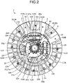
- FIG. 2 is an elevational view of the exemplary damper device 1 of the first embodiment with part of the disc plate 22 cut away.
- the disc plate 22 has a disc shape extending in the radial directions.
- the two disc plates 22 each have an inner frame 22a, an outer frame 22b, two first frames 22c, and two second frames 22d.
- FIG. 2 illustrates only one of the two first frame 21c.
- the numbers of the first frames 22c and the second frames 22d are not limited to this example.
- the inner frame 22a has a disc shape extending in the radial directions and is provided with a fitting hole 22e extending along the axis Ax.
- the inner frame 22a is further provided with a spline 22f.
- the spline 22f is formed of a plurality of grooves extending in the radial directions from the inner circumference of the fitting hole 22e.
- one of the bosses 21a of the bush 21 fits into the fitting hole 22e.
- the joints 21b protruding from the boss 21a are fit into the spline 22f of the disc plate 22.
- the disc plate 22 is attached to the bush 21, and the disc plate 22 and the bush 21 are integrally rotatable about the axis Ax.
- the outer frame 22b has a disc shape surrounding the inner frame 22a with spacing.
- the first frames 22c and the second frames 22d connect the outer circumference of the inner frame 22a and the inner circumference of the outer frame 22b.
- the two first frames 22c extend from the inner frame 22a in radially opposite directions.
- the two second frames 22d extend from the inner frame 22a in radially opposite directions.
- the extending direction of the first frames 22c and the extending direction of the second frames 22d are substantially orthogonal to each other, the extending directions of the first and second frames 22c and 22d are not limited to this example.
- the inner frame 22a, the outer frame 22b, the first frames 22c, and the second frames 22d define a plurality of openings 22g.
- the openings 22g expose the inside of the damper device 1 covered with the disc plate 22.
- the two disc plates 22 are juxtaposed with a gap in the axial directions.
- the two disc plates 22 are connected to each other through a first connecting member 27 extending in the axial directions.
- Both ends of the first connecting member 27 are fixed to the two disc plates 22 by caulking, for example.
- the first connecting member 27 restricts relative rotation of the two disc plates 22.
- the two disc plates 22 are integrally rotatable about the axis Ax.
- the two disc plates 22 have substantially the same shape, however, they may have different shapes.
- the inner frames 22a, the outer frames 22b, the first frames 22c, and the second frames 22d of the two disc plates 22 are juxtaposed in the axial directions. Consequently, the openings 22g of one of the disc plates 22 and the openings 22g of the other disc plate 22 are at corresponding positions.
- the support plate 24 has a disc shape larger than the outer frame 22b of the disc plate 22.
- An inner circumferential part of the support plate 24 is attached to the outer frame 22b of the one of the disc plates 22 through the first connecting member 27 or with a screw, for example.
- the support plate 24 extends radially outward from the outer frame 22b of the disc plate 22.
- the support plate 24 may be attached to another part.
- the linings 25 have a disc shape surrounding the disc plate 22 with spacing, for example.
- the two linings 25 are attached to both axial sides of the outer circumference of the support plate 24.
- the two linings 25 are in contact with the flywheel.
- the drive plate 2 Along with the rotation of the flywheel, the drive plate 2 is rotated by a frictional force between the flywheel and the linings 25. Excessive torque acting on the damper device 1 causes sliding between the linings 25 and the flywheel.
- the intermediate plate 3 is located between the two disc plates 22 in the axial directions.
- the intermediate plate 3 includes two plates 31.
- the two plates 31 are juxtaposed with a gap in the axial directions.
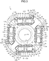
- FIG. 3 is an elevational view of the damper device 1 of the first embodiment with the drive plate 2 omitted. As illustrated in FIG. 3 , each of the plates 31 includes an intermediate part 33 and two arms 34. The number of the arms 34 is not limited to two.
- the intermediate part 33 has a disc shape expanding in the radial directions and is provided with an insertion hole 33a extending along the axis Ax. As illustrated in FIG. 1 , the boss 21a of the bush 21 of the drive plate 2 is fit into the insertion hole 33a. The boss 21a and the plate 31 are relatively rotatable about the axis Ax.
- the boss 21a fits into the insertion hole 33a to limit radial movement of the plate 31.
- the boss 21a of the bush 21 places (centers) the plate 31 in line with the axis Ax.
- the two arms 34 extend in radially opposite directions from the intermediate part 33.
- the two arms 34 extend upward to the left and downward to the right.
- the length from the axis Ax to the outer circumference of each arm 34 is shorter than the length from the axis Ax to the outer circumference of the outer frame 22b of the disc plate 22.
- the arms 34 are each provided with two projections 35 near the tip.
- the projections 35 are an exemplary restrictor.
- the projections 35 protrude from the arm 34 to both sides substantially in the circumferential directions. In other words, the two projections 35 protrude in circumferentially opposite directions from the tip of the arm 34.
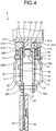
- FIG. 4 is a sectional view of part of the exemplary damper device 1 of the first embodiment at a position different from in FIG. 1 .
- a second connecting member 36 extends in the axial directions and is attached to the two plates 31.
- the second connecting member 36 connects the two plates 31 to each other. Both ends of the second connecting member 36 are fixed to the two plates 31 by caulking, for example.
- the second connecting member 36 restricts the two plates 31 from relatively rotating. Thus, the two plates 31 are integrally rotatable about the axis Ax.
- the two plates 31 have substantially the same shape but they may have different shapes.
- the intermediate parts 33 and the arms 34 of the two plates 31 are juxtaposed in the axial directions.
- the arms 34 of one of the plates 31 and the arms 34 of the other plate 31 are at corresponding positions.
- the driven plate 4 is connected to a transmission via an input shaft, for example.
- the driven plate 4 may be connected to another device such as a motor in place of the transmission.
- the driven plate 4 includes an inner hub 41, an outer hub 42, and a spring 43.
- the inner hub 41 includes a boss 41a and a plurality of joints 41b.
- the boss 41a has a substantially cylindrical shape extending along the axis Ax.
- the input shaft is fit into the boss 41a. Rotation is transmitted between the boss 41a and the input shaft via a spline or a key, for example.
- the boss 41a of the inner hub 41 is fit in the bosses 21a of the bush 21 of the drive plate 2.
- the boss 41a of the inner hub 41 and the bosses 21a of the bush 21 are relatively rotatable about the axis Ax.
- the joints 41b protrude in the radial directions from the outer circumference of the boss 41a.
- the joints 41b are located between the two bosses 21a of the bush 21 of the drive plate 2 in the axial directions.
- the outer hub 42 is located between the two plates 31 of the intermediate plate 3 in the axial directions.
- the location of the outer hub 42 is not limited to this example and may be located outside the two plates 31.
- the outer hub 42 includes an intermediate part 42a and two arms 42b.
- FIG. 3 illustrates the driven plate 4 with the inner hub 41 and the spring 43 omitted.
- the number of the arms 42b is not limited to two.
- the intermediate part 42a has a disc shape expanding in the radial directions and is provided with an insertion hole 42c extending along the axis Ax.
- the intermediate part 42a is further provided with a spline 42d.
- the spline 42d is formed of a plurality of grooves extending in the radial directions from the inner circumference of the insertion hole 42c.
- the boss 41a of the inner hub 41 is fit into the insertion hole 42c of the outer hub 42.
- the boss 41a of the inner hub 41 and the outer hub 42 are relatively rotatable about the axis Ax.
- the joints 41b of the inner hub 41 are fit into the spline 42d of the outer hub 42. In the circumferential directions, there is a gap between the end of the spline 42d of the outer hub 42 and the end of the joints 41b of the inner hub 41. Thus, the inner hub 41 and the outer hub 42 are relatively rotatable at a certain angle.
- the spring 43 is a coil-shaped compression spring.
- the spring 43 is situated in a gap between the end of the spline 42d of the outer hub 42 and the end of the joints 41b of the inner hub 41 in the circumferential directions. In other words, the spring 43 is intervenient between the inner hub 41 and the outer hub 42 in the circumferential directions.
- the spring 43 is compressed by the end of the spline 42d of the outer hub 42 and the end of the joints 41b of the inner hub 41 in the circumferential directions.
- the spring 43 exerts a force on the inner hub 41 and the outer hub 42 relatively rotating about the axis Ax in one direction to cause them to rotate in the opposite direction.
- the two arms 42b of the outer hub 42 extend in radially opposite directions from the intermediate part 42a.
- the two arms 42b extend upward to the right and downward to the left.
- the length from the axis Ax to the outer circumference of each arm 42b is shorter than the length from the axis Ax to the outer circumference of the outer frame 22b of the disc plate 22.
- the arms 42b of the outer hub 42 are overlaid on the first frame 22c of the disc plate 22 of the drive plate 2 in the axial directions.
- the positions of the arms 42b of the outer hub 42 and the first frame 22c of the disc plate 22 are not limited to this example.
- the arms 42b each include two overhangs 42e at the tip.
- the overhangs 42e protrude from the tip of the arm 42b to both sides in the circumferential directions. In other words, the two overhangs 42e protrude in circumferentially opposite directions from the tip of the arm 42b.
- the damper device 1 further includes four torsion springs 5, four first sheets 6, and four second sheets 7.
- the second sheets 7 are an exemplary support member.
- the numbers of the torsion springs 5 and the first and second sheets 6 and 7 are not limited to this example.
- each torsion spring 5 is a coil-shaped compression spring (a coil spring).
- the torsion spring 5 is located between the arm 42b of the outer hub 42 of the driven plate 4 and the arm 34 of the plate 31 of the intermediate plate 3 in the circumferential directions.
- the torsion spring 5 is located between the first frame 22c of the disc plate 22 of the drive plate 2 and the arm 34 of the plate 31 of the intermediate plate 3.
- the first sheets 6 and the second sheets 7 are made of a synthetic resin material, for example.
- the first sheets 6 and the second sheets 7 may be made of another material.
- the four first sheets 6 are detachably supported by both circumferential sides of the two first frames 22c of the disc plate 22 of the drive plate 2. As illustrated in FIG. 3 , the four first sheets 6 are also detachably supported by both circumferential sides of the two arms 42b of the outer hub 42 of the driven plate 4, respectively. The first sheets 6 are supported by the overhangs 42e of the arms 42b of the outer hub 42.
- the four first sheets 6 each include a support wall 61, two extension walls 62, a convex portion 63, and a cover 64.
- the support wall 61 covers a circumferential end of the arm 42b of the outer hub 42 of the driven plate 4.
- the support wall 61 supports one end 5a of the torsion spring 5.
- the two extension walls 62 extend in the circumferential directions from the support wall 61 and are juxtaposed with a gap in the axial directions.
- the arm 42b of the outer hub 42 is located between the two extension walls 62.
- the two extension walls 62 are located between the first frames 22c of the two disc plates 22 of the drive plate 2.
- the arm 42b of the outer hub 42 and the first frame 22c of the disc plate 22 work to restrict the first sheet 6 from moving in the axial directions.
- the support wall 61 is provided with a recess 65.
- the recess 65 is a bottomed hole opening in the circumferential directions and is located between the two extension walls 62 in the axial directions.
- the overhang 42e of the outer hub 42 is fit into the recess 65.
- the first sheet 6 is supported by the overhang 42e of the outer hub 42.
- the overhang 42e of the outer hub 42 is provided with a convex portion 42f which is inserted into the recess 65, for example.
- the convex portion 42f in contact with the inner face of the recess 65, the overhang 42e of the outer hub 42 supports the first sheet 6.
- gap G at least either radially inside or outside the overhang 42e across the convex portion 42f and the recess 65. That is to say, while the outer hub 42 supports the first sheet 6, the gap (space) G lies between the outer hub 42 and the first sheet 6.
- the first sheet 6 is rotatable (swingable) with respect to the outer hub 42 in a plane orthogonal to the axial directions. That is, as viewed in the axial directions in FIG. 3 , the first sheet 6 can rotate about the rotational center extending parallel to the axis Ax.
- the rotational center of the first sheet 6 corresponds to a contact point between the convex portion 42f and the recess 65, for example, and is changeable in position in accordance with the rotation of the first sheet 6.
- the first sheet 6 is rotatable with respect to the driven plate 4 while changing the position of the rotational center parallel to the axis Ax.
- the rotational center of the first sheet 6 may be at a fixed position.
- the first frame 22c of the disc plate 22 of the drive plate 2 is provided with an accommodation part 22h.
- the accommodation part 22h is a recess opening in the circumferential directions.
- the extension walls 62 of the first sheet 6 are individually fit in the accommodation part 22h.
- the extension walls 62 of the first sheet 6 contact with the inner face of the accommodation part 22h.
- the first sheet 6 is rotatably supported by the first frame 22c of the disc plate 22 in the plane orthogonal to the axial directions.
- the first sheet 6 is rotatable about the supported part by the driven plate 4 and the drive plate 2, in a direction toward or away from the axis Ax.
- the first sheet 6 is rotatable within a certain range. That is to say, when rotating until no gap G remains, the first sheet 6 comes into contact with the driven plate 4 or the drive plate 2 and is restricted from rotating further.
- first sheet 6 is supported by either the driven plate 4 or the drive plate 2.
- the driven plate 4 moves leftward in FIG. 2 , for example.
- first sheets 6A are supported by the driven plate 4 and separated from the drive plate 2.
- the other first sheets 6B are supported by the drive plate 2 and separated from the driven plate 4 in the circumferential directions.
- the first sheets 6A of the first sheets 6 are located in the counterclockwise direction of the first frame 22c of the drive plate 2 and the arm 42b of the driven plate 4.
- the first sheets 6B of the first sheets 6 are located in the clockwise direction of the first frame 22c of the drive plate 2 and the arm 42b of the driven plate 4.
- the convex portion 63 protrudes from the support wall 61 substantially in the circumferential directions.
- the convex portion 63 protrudes toward the arm 34 of the plate 31 of the intermediate plate 3, for example.
- the convex portion 63 has a substantially cylindrical shape but may have another shape.
- the convex portion 63 is inserted into the torsion spring 5 from the end 5a.
- the convex portion 63 is situated inside the torsion spring 5.
- the convex portion 63 restricts the torsion spring 5 from moving in the radial directions and the axial directions.
- the cover 64 extends from the support wall 61 in the circumferential directions.
- the cover 64 extends in a direction opposite to the two extension walls 62.
- the cover 64 covers part of the torsion spring 5 from radially outside. When the torsion spring 5 bends radially outward by a centrifugal force, the cover 64 comes into contact with the torsion spring 5 to restrict the torsion spring 5 from moving radially outward.
- the four second sheets 7 are supported by both circumferential sides of the two arms 34 of the plate 31 of the intermediate plate 3, respectively.
- the four second sheets 7 each have a support wall 71 and a convex portion 72.
- FIG. 5 is an elevational view of an example of part of the intermediate plate 3 and the second sheet 7 of the first embodiment.
- the support wall 71 covers a circumferential end of the arm 34 of the plate 31 of the intermediate plate 3.
- the support wall 71 supports the other end 5b of the torsion spring 5.
- the support wall 71 includes an intervenient part 71a and two sides 71b.
- the intervenient part 71a and the two sides 71b are integrated together. In the axial directions, the intervenient part 71a is located between the two sides 71b.
- the intervenient part 71a is located between the arms 34 of the two plates 31 of the intermediate plate 3 in the axial directions. Thereby, the arms 34 of the two plates 31 of the intermediate plate 3 restrict the second sheet 7 from moving in the axial directions.
- the two sides 71b are at substantially the same position as the arms 34 of the two plates 31 of the intermediate plate 3 in the axial directions.
- the two sides 71b are each provided with a concave portion 74.
- the concave portion 74 is a cutout opening in the axial directions and toward the arm 34 in the circumferential directions.
- the projection 35 of the intermediate plate 3 is contained in the concave portion 74, whereby the second sheet 7 is supported by the two arms 34 of the plate 31 of the intermediate plate 3.
- the arms 34 of the intermediate plate 3 each have two first side edges 34a and two second side edges 34b.
- the two first side edges 34a are both circumferential side edges of the arm 34.
- the first side edges 34a are located between the intermediate part 33 and the projection 35 in the radial directions.
- the two second side edges 34b are also both circumferential side edges of the arm 34.
- the second side edges 34b are each located between the projection 35 and the tip of the arm 34. Consequently, the projection 35 is located between the first side edge 34a and the second side edge 34b.
- the projection 35 protrudes from the side edges (the first and second side edges 34a and 34b) of the arm 34 of the intermediate plate 3.
- the projection 35 includes a protruding part 35a and a hook 35b.
- the hook 35b can also be referred to as a tab, a latch, or a convex portion, for example.
- the protruding part 35a protrudes from the arm 34 in a direction crossing the radial directions, as viewed in the axial directions in FIG. 5 .
- the protruding part 35a protrudes toward the first sheet 6 supported by the drive plate 2 and the driven plate 4.
- the protruding part 35a may protrude in another direction such as the circumferential directions.
- the protruding part 35a has a substantially rectangular plate shape, for example.
- the hook 35b protrudes from the distal end of the protruding part 35a toward the axis Ax in the radial directions. In other words, the hook 35b extends toward the axis Ax from the basal end to the distal end.
- the hook 35b may protrude from another location or in another direction such as radially inward as long as it protrudes from the protruding part 35a away from the arm 34 in the circumferential directions.
- the projection 35 has a wider width W1 at the distal end than a width W2 at a part closer to the arm 34 than the distal end.
- the widths W1 and W2 are the lengths of the projection 35 in a direction orthogonal to the protruding direction of the protruding part 35a from the arm 34.
- the width W2 is the smallest width of the projection 35.
- the projection 35 includes a part closer to the arm 34 than a certain part and smaller in width than the certain part.
- the projection 35 has a curved edge 35c.
- the curved edge 35c can also be referred to as a recess or a concave portion, for example.
- the curved edge 35c is located between the hook 35b and the first side edge 34a.
- the curved edge 35c of the projection 35 is an arc-shaped edge recessed radially outward.
- the projection 35 is contained in the concave portion 74 of the second sheet 7.
- the side 71b of the second sheet 7 includes a first contact edge 71ba, a second contact edge 71bb, a first inner edge 71bc, and a second inner edge 71bd.
- the first contact edge 71ba faces the first side edge 34a of the arm 34.
- the second contact edge 71bb faces the second side edge 34b of the arm 34.
- the second contact edge 71bb s part of the concave portion 74.
- the first inner edge 71bc is connected to an end of the first contact edge 71ba and has an arc shape.
- the first inner edge 71bc faces the curved edge 35c of the projection 35.
- the first inner edge 71bc has substantially the same radius as the curved edge 35c of the projection 35 and is in contact with the curved edge 35c.
- the side 71b of the support wall 71 is provided with an engaging part 71be.
- the engaging part 71be is a substantially semicircular part defined by the first inner edge 71bc.
- the engaging part 71be is located between the arm 34 and the hook 35b in the circumferential directions.
- the second inner edge 71bd connects an end of the first inner edge 71bc and an end of the second contact edge 71bb to each other.
- the second inner edge 71bd faces the projection 35 with spacing.
- the first and second inner edges 71bc and 71bd form part of the concave portion 74.
- the part of the concave portion 74 formed by the first and second inner edges 71bc and 71bd has a substantially rectangular shape extending from the first and second contact edges 71ba and 71bb substantially in the circumferential directions.
- the end of the concave portion 74 has a wider width W3 than a width W4 of a part closer to the first and second contact edges 71ba and 71bb than the end.
- the widths W3 and W4 are the lengths of the concave portion 74 in a direction orthogonal to the extending direction of the concave portion 74.
- the width W4 is the smallest width of the concave portion 74.
- the concave portion 74 has a part closer to the first and second contact edges 71ba and 71bb than a certain part and smaller in width than the certain part.
- the second sheet 7 is supported by the projection 35.
- the second sheet 7 supported by the projection 35 is rotatable (swingable) with respect to the arm 34 in a plane orthogonal to the axis Ax. That is to say, as viewed in the axial directions in FIG. 5 , the second sheet 7 can rotate about the rotational center extending parallel to the axis Ax.
- the rotational center of the second sheet 7 corresponds to a contact point between the curved edge 35c and the first inner edge 71bc, for example, and is changeable in position in accordance with the rotation of the second sheet 7.
- the second sheet 7 is rotatable with respect to the intermediate plate 3 while changing the position of the rotational center parallel to the axis Ax.
- the rotational center of the second sheet 7 may be at a fixed position such as the center of the arc-shaped first inner edge 71bc.
- the gap G between the first side edge 34a and the first contact edge 71ba decreases. With no gap G remaining, the first side edge 34a comes into contact with the first contact edge 71ba.
- the second sheet 7 is to further rotate toward the axis Ax about a contact point between the first side edge 34a and the first contact edge 71ba as a fulcrum point.
- the hook 35b supports the engaging part 71be of the second sheet 7 to limit the second sheet 7 from further rotating.
- the gap G between the second side edge 34b and the second contact edge 71bb decreases. With no gap G remaining, the second side edge 34b comes into contact with the second contact edge 71bb as in FIG. 5 .
- the second sheet 7 is to further rotate away from the axis Ax about a contact point between the second side edge 34b and the second contact edge 71bb as fulcrum point.
- the hook 35b supports the engaging part 71be of the second sheet 7 to restrict the second sheet 7 from further rotating.
- the projection 35 restricts the second sheet 7 from rotating beyond a certain angle.
- the hook 35b comes into contact with the engaging part 71be of the second sheet 7 which is to moves away from the arm 34 in the circumferential directions, to thereby restrict the second sheet 7 from further moving.
- the first inner edge 71bc may slide with respect to the hook 35b, causing the second sheet 7 to slightly move away from the arm 34 in the circumferential directions.
- the hook 75b comes into contact with the engaging part 71be again to restrict the second sheet 7 from further moving.
- the projection 35 restricts the second sheet 7 from moving away from the arm 34 in the circumferential directions.
- the projection 35 comes into contact with the first inner edge 71bc or the second inner edge 71bd of the concave portion 74 to restrict the second sheet 7 from further moving.
- the projection 35 restricts the second sheet 7 from moving with respect to the arm 34 in the radial directions.
- the projection 35 of the intermediate plate 3 rotatably supports the second sheet 7.
- the projection 35 of the intermediate plate 3 and the concave portion 74 of the second sheet 7 are fit together, thereby restricting the radial and circumferential movements of the second sheet 7 with respect to the intermediate plate 3 and restricting the rotation of the second sheet 7 beyond a certain angle.
- the convex portion 72 of the second sheet 7 protrudes from the support wall 71 substantially in the circumferential directions.
- the convex portion 72 of the second sheet 7 protrudes toward the first sheet 6.
- the convex portion 63 of the first sheet 6 protrudes toward the second sheet 7.
- the convex portion 72 has a substantially cylindrical shape but may have another shape.
- the convex portion 72 is inserted into the torsion spring 5 from the end 5b. In other words, the convex portion 72 is placed inside the torsion spring 5. Thus, the convex portion 72 restricts the torsion spring 5 from moving in the radial directions and the axial directions.
- the torsion spring 5 is intervenient between the first sheet 6 supported by the driven plate 4 and the drive plate 2, and the second sheet 7 supported by the intermediate plate 3 in the circumferential directions. Consequently, the first sheet 6 intervenes between the driven plate 4 and the drive plate 2, and the torsion spring 5.
- the second sheet 7 is intervenes between the intermediate plate 3 and the torsion spring 5.
- the clockwise direction is an exemplary one of rotational directions.
- first torsion springs 51 two of the four torsion springs 5 are referred to as first torsion springs 51, whereas the other two of the four torsion springs 5 are referred to as second torsion springs 52.
- the first torsion springs 51 are an exemplary first elastic element.
- the second torsion springs 52 are an exemplary second elastic element.
- the first torsion springs 51 and the second torsion springs 52 are arranged alternately in the circumferential directions.
- second sheets 7A two of the four second sheets 7 are referred to as second sheets 7A, whereas the other two of the four second sheets 7 are referred to as second sheets 7B.
- the second sheets 7A are located in the counterclockwise direction of the intermediate plate 3.
- the second sheets 7B are located in the clockwise direction of the intermediate plate 3.
- the first torsion springs 51 are each located between the arm 42b of the driven plate 4 to rotate and the arm 34 of the intermediate plate 3 toward which the driven plate 4 moves. Consequently, the first torsion spring 51 is located between the first sheet 6B and the second sheet 7A.
- the second torsion springs 52 are each located between the arm 34 of the intermediate plate 3 and the first frame 22c of the drive plate 2 toward which the intermediate plate 3 moves. Consequently, the second torsion spring 52 is located between the first sheet 6A and the second sheet 7B.
- the driven plate 4 rotates clockwise with respect to the intermediate plate 3, for example, while decreasing in angle relative to the intermediate plate 3 about the axis Ax. This shortens the distance between the first sheet 6B supported by the driven plate 4 and the second sheet 7A supported by the intermediate plate 3, to elastically compress the first torsion spring 51 supported by the first sheet 6B and the second sheet 7A. The compressed first torsion spring 51 pushes the intermediate plate 3 and the driven plate 4 so as to increase the angle between the intermediate plate 3 and the driven plate 4.
- the intermediate plate 3 rotates clockwise with respect to the drive plate 2, while decreasing in angle relative to the drive plate 2 about the axis Ax. This shortens the distance between the first sheet 6A supported by the drive plate 2 and the second sheet 7B supported by the intermediate plate 3, to elastically compress the second torsion spring 52 supported by the first sheet 6A and the second sheet 7B. The compressed second torsion spring 52 pushes the drive plate 2 and the intermediate plate 3 so as to increase the angle between the drive plate 2 and the intermediate plate 3.
- the angle between the drive plate 2 and the intermediate plate 3 about the axis Ax is maintained constant by the four torsion springs 5.
- the angle between the intermediate plate 3 and the driven plate 4 is maintained constant.
- the extending direction of the arms 34 of the intermediate plate 3 and the extending direction of the arms 42b of the driven plate 4 are substantially orthogonal to each other. The extending directions of the arms 34 and 42b are not limited to this example.
- the torsion springs 5 push the first sheets 6 toward the drive plate 2 and the driven plate 4. Thereby, the first sheets 6 are supported by at least one of the drive plate 2 and the driven plate 4. Similarly, the torsion springs 5 push the second sheets 7 toward the intermediate plate 3. Thereby, the second sheets 7 are supported by the intermediate plate 3.
- the torsion springs 5 push the first sheets 6 and the second sheets 7 that are rotatable.
- the support walls 61 of the first sheets 6 and the support walls 71 of the second sheets 7 are maintained substantially in parallel to each other while no external force acts on the drive plate 2 and the driven plate 4.
- the drive plate 2 of the damper device 1 is connected to the crankshaft of the engine via the flywheel.
- the driven plate 4 is connected to the transmission via the input shaft. Torque is transmitted to the flywheel by driving of the engine and transmitted from the drive plate 2 to the driven plate 4 via the first sheet 6, the torsion spring 5, the second sheet 7, the intermediate plate 3, the second sheet 7, the torsion spring 5, and the first sheet 6, for example.
- the driven plate 4 transmits the torque to the transmission via the input shaft.
- the rotational speed of the crankshaft of the engine fluctuates by a driver's operation and/or the stroke of the engine. Because of such a variation in the rotational speed of the crankshaft, the rotational speed of the input shaft may exceed the rotational speed of the crankshaft. In this case, torque can be transmitted from the driven plate 4 to the drive plate 2 via the first sheet 6, the torsion spring 5, the second sheet 7, the intermediate plate 3, the second sheet 7, the torsion spring 5, and the first sheet 6, for example.
- the first torsion springs 51 and the second torsion springs 52 are connected in series.
- the spring constant of two serially connected springs is calculated as a quarter of the spring constant of the two parallel-connected springs. Consequently, the damper device 1 including the first torsion spring 51 and the second torsion spring 52 connected in series may be lower in torsional rigidity than the one including the first torsion spring 51 and the second torsion spring 52 connected in parallel.
- first torsion springs 51 and the second torsion springs 52 have substantially the same spring constant.
- first torsion springs 51 and the second torsion springs 52 may have different spring constants, so that the damper device 1 may exert different torsional rigidities that change in accordance with a torsional angle, for example.
- the damper device 1 further includes a plurality of first friction members 11, a first leaf spring 12, a plurality of second friction members 13, and a second leaf spring 14.
- the first and second friction members 11 and 13 can also be referred to as thrust members, for example.
- the first friction members 11 are attached to the two disc plates 22 of the drive plate 2, respectively.
- the first friction members 11 are intervenient between the drive plate 2 and the intermediate plate 3 in the axial directions.
- the first friction members 11 generate a frictional force with the intermediate plate 3.
- the first leaf spring 12 is intervenient between the first friction member 11 and the disc plate 22.
- the first leaf spring 12 pushes the first friction member 11 toward the intermediate plate 3.
- the first leaf spring 12 increases the frictional force occurring between the first friction member 11 and the intermediate plate 3.
- the second friction members 13 are attached to the two plates 31 of the intermediate plate 3, respectively.
- the second friction member 13 are intervenient between the intermediate plate 3 and the driven plate 4 in the axial directions.
- the second friction members 13 generate a frictional force with the driven plate 4.
- the second leaf spring 14 is intervenient between the second friction member 13 and the plate 31 of the intermediate plate 3.
- the second leaf spring 14 pushes the second friction member 13 toward the driven plate 4.
- the second leaf spring 14 increases the frictional force occurring between the second friction member 13 and the driven plate 4.
- FIG. 6 is an elevational view of a part of the exemplary damper device 1 of the first embodiment.
- FIG. 7 is an elevational view of the part of the exemplary damper device 1 of the first embodiment when the intermediate plate 3 and the driven plate 4 relatively rotate.
- the drive plate 2, the intermediate plate 3, and the driven plate 4 in response to torque acting on the damper device 1, relatively rotate about the axis Ax.
- the torque acting on the damper device 1 causes a decrease in an angle ⁇ b between the intermediate plate 3 and the driven plate 4, causing a torsional angle ⁇ t in FIG. 7 , for example.
- the angle ⁇ b between the arm 34 of the plate 31 of the intermediate plate 3 and the arm 42b of the outer hub 42 of the driven plate 4 decreases.
- the angle between the first frame 22c of the disc plate 22 of the drive plate 2 and the arm 34 of the plate 31 of the intermediate plate 3 also decreases.
- the convex portion 63 of the first sheet 6 comes into contact with the convex portion 72 of the second sheet 7.
- the contact between the convex portion 63 of the first sheet 6 and the convex portion 72 of the second sheet 7 works to restrict the angle between the drive plate 2 and the intermediate plate 3 from further decreasing.
- the first and second sheets 6 and 7 contact with each other to restrict the torsion spring 5 from further contracting.
- the first and second sheets 6 and 7 contact with each other to inhibit the torsion springs 5 from being excessively compressed to a contact limit.
- the distal end part of the arm 34 moves a longer distance than the basal end part (intermediate part 33 side) of the arm 34 does. Consequently, during no rotation of the second sheet 7, the torsion spring 5 exerts larger contraction and load from the radially outside part than from the radially inside part.
- each torsion spring 5 exerts different contractions and loads in the radial directions, therefore, the torsion spring 5 elastically pushes the second sheet 7 so as to make contractions and loads more uniform in the radial directions.
- the second sheet 7 is rotated, making the radial contraction of the torsion spring 5 more uniform.
- the second sheet 7 rotates such that the second contact edge 71bb approaches the second side edge 34b, for example.
- the radial outside parts of the first frame 22c and the arm 42b move a longer distance than the radially inside parts thereof. Consequently, during no rotation of the first sheet 6, the torsion spring 5 exerts larger contraction and load from the radially outside part than from the radially inside part.
- each torsion spring 5 exerts different contractions and loads in the radial directions, therefore, the torsion spring 5 elastically pushes the first sheet 6 so as to make contractions and loads more uniform in the radial directions.
- the radially outside part of the torsion spring 5, which exerts larger contraction and load, pushes the first sheet 6 with a greater reactive force, for example.
- the radially inside part of the torsion spring 5, which exerts smaller contraction and load, pushes the first sheet 6 with a smaller reactive force.
- the damper device 1 rotates about the axis Ax by torque transmitted from the crankshaft. By this rotation, a centrifugal force acts on the torsion spring 5, the first sheet 6, and the second sheet 7.
- the second sheet 7 In response to the centrifugal force, the second sheet 7 is to move radially outward. However, the projection 35 of the intermediate plate 3 supports the second sheet 7 to restrict the second sheet 7 from moving radially outward.
- the second sheet 7 supported by the projection 35 is to rotate away from the axis Ax about a contact point between the projection 35 and the second sheet 7 as a fulcrum point, for example.
- the hook 35b of the projection 35 in FIG. 5 supports the engaging part 71be of the second sheet 7 to restrict the second sheet 7 from rotating away from the axis Ax.
- the intermediate plate 3 supports the second sheet 7 by the contact point between the hook 35b and the engaging part 71be and the contact point between the second side edge 34b and the second contact edge 71bb, for example. Thereby, the intermediate plate 3 restricts the second sheet 7 from rotating away from the axis Ax.
- the second sheet 7 is restricted from moving radially outward and rotating away from the axis Ax, so that the second sheet 7 is maintained in the supported state by the projection 35 of the intermediate plate 3 irrespective of receipt of a centrifugal force. This can prevent the second sheet 7 and the torsion spring 5 from being detached from the intermediate plate 3.
- the projection 35 of the intermediate plate 3 serves to rotatably support the second sheet 7 in the plane orthogonal to the axis Ax and restrict the second sheet 7 from separating from the intermediate plate 3 in the circumferential directions. Because of this, along with the rotation of the driven plate 4 toward the intermediate plate 3, the second sheet 7 can rotate such that the radially outside part and the radially inside part of the first torsion spring 51 can be substantially uniform in terms of load and length. This can reduce degradation in damping performance and strength, which would otherwise occur due to the non-uniform length and load of the first torsion spring 51.
- the projection 35 works to restrict the second sheet 7 from rotating beyond a certain angle and from separating from the intermediate plate 3 in the circumferential directions. That is to say, the projection 35 restricts the second sheet 7 from rotating at a fixed position and from rotating while circumventing the projection 35 in the circumferential directions, thereby inhibiting the second sheet 7 and the first torsion spring 51 from being detached from the intermediate plate 3.
- This can eliminate the necessity for adding, on the outer circumferential side of the first torsional spring 51, a member that restricts the first torsional spring 51 from moving radially outward and/or for downsizing the first torsional spring 51, which makes it possible to place the first torsional spring 51 further radially outside.
- the first torsional spring 51 is prevented from lowering in damping performance (torsional characteristics) and strength, and the damper device 1 is inhibited from increasing in size.
- the projection 35 includes the hook 35b that comes into contact with the second sheet 7 which is to move away from the intermediate plate 3 in the circumferential directions. Thereby, the second sheet 7, which is to rotate, circumventing the projection 35 in the circumferential directions, is caught by the hook 35b, to further inhibit the second sheet 7 and the first torsional spring 51 from being detached from the intermediate plate 3.
- the projection 35 includes the hook 35b protruding toward the axis Ax in the radial directions
- the second sheet 7 includes the engaging part 71be located between the intermediate plate 3 and the hook 35b in the circumferential directions.
- FIG. 8 is an elevational view of an example of a part of the intermediate plate 3 and the second sheet 7 according to the second embodiment.
- the hook 35b of the second embodiment protrudes from the tip of the protruding part 35a toward the opposite side of the axis Ax in the radial directions.
- the curved edge 35c is located between the first side edge 34a and the tip of the protruding part 35a.
- the engaging part 71be of the second sheet 7 is defined by the second contact edge 71bb and the second inner edge 71bd.
- the engaging part 71be is located between the arm 34 and the hook 35b in the circumferential directions.
- the projection 35 also includes the hook 35b that comes into contact with the second sheet 7 when the second sheet 7 is to move away from the intermediate plate 3 in the circumferential directions, as with the first embodiment.
- the second sheet 7, which is to rotate, circumventing the projection 35 in the circumferential directions, is caught by the hook 35b, and thus the second sheet 7 and the first torsional spring 51 are further inhibited from being detached from the intermediate plate 3.
Landscapes
- Engineering & Computer Science (AREA)
- General Engineering & Computer Science (AREA)
- Mechanical Engineering (AREA)
- Physics & Mathematics (AREA)
- Acoustics & Sound (AREA)
- Aviation & Aerospace Engineering (AREA)
- Mechanical Operated Clutches (AREA)
- Springs (AREA)
Abstract
Description
- The present invention relates to a damper device.
- Conventionally, damper devices to be set between the output shaft of an engine and the input shaft of a transmission are known. A damper device includes two rotational elements connected to the output shaft and the input shaft, and an elastic element such as a coil spring intervenient between these rotational elements, for example. Such a damper device serves to damp rotational fluctuations from the engine with the elastic element.
- A centrifugal force acts on the elastic element of the damper device. To prevent the elastic element from being detached from the rotational elements by the centrifugal force, the rotational elements are partially extended and placed closer to the outer circumference of the elastic element, for example (Patent Literature 1).
- Patent Document 1: Japanese Patent Application Laid-open No.
2015-161372 - However, placing the extended part on the outer circumferential side of the elastic element results in increasing the size of the damper device. To prevent the damper device from increasing in size, the elastic element may be placed more radially inward, however, this will cause degradation in the torsional characteristics of the damper device.
- In view of the above, the present invention provides a damper device including an elastic element placeable further radially outside.
- A damper device according to one embodiment of the present invention, as an example, includes: a first rotational element rotatable about a rotational center; a second rotational element rotatable about the rotational center; a third rotational element rotatable about the rotational center; a first elastic element that is located between the first rotational element and the third rotational element and is elastically compressed by relative rotation of the first rotational element with respect to the third rotational element in one of rotational directions; a second elastic element that is located between the third rotational element and the second rotational element and is elastically compressed by relative rotation of the third rotational element with respect to the second rotational element in the one of the rotational directions; a support member that is intervenient between the third rotational element and the first elastic element, to support the first elastic element; and a restrictor provided with the third rotational element, to: rotatably support the support member in a plane orthogonal to the rotational center, restrict the support member from rotating beyond a certain angle, and restrict the support member from moving away from the third rotational element in the rotational directions. Consequently, as an example, the restrictor inhibits the support member and the first elastic element from being detached from the third rotational element, which makes it possible to place the first elastic element further radially outward without adding, on the outer circumferential side of the first elastic element, a member that restricts the first elastic element from moving radially outward.
- In the damper device, as an example, the restrictor includes: a protrusion that protrudes from the third rotational element in a direction crossing radial directions, as viewed in axial directions, and a hook that protrudes from the protrusion away from the third rotational element in the rotational directions and comes into contact with the support member which is to move away from the third rotational element in the rotational directions. Consequently, as an example, the hook catches the support member which is to rotate, circumventing the restrictor in the rotational directions; thus, the support member and the first elastic element are further inhibited from being detached from the third rotational element.
- In the damper device, as an example, the hook protrudes from the protrusion toward the rotational center in the radial directions, and the support member includes an engaging part located between the third rotational element and the hook in the rotational directions. Consequently, as an example, the hook catches the engaging part of the support member which is to rotate away from the rotational center; thus, the support member and the first elastic element are further inhibited from being detached from the third rotational element.
- In the damper device, as an example, the hook extends toward the rotational center from a basal end to a distal end. Consequently, as an example, the hook catches the engaging part of the support member which is to rotate away from the rotational center; thus, the support member and the first elastic element are further inhibited from being detached from the third rotational element.
- In the damper device, as an example, the third rotational element includes an arm extending in the radial directions, and the restrictor protrudes from an edge of the arm in the rotational directions. Consequently, as an example, the support member is inhibited from moving in the radial directions.
- In the damper device, as an example, in a first width direction orthogonal to a direction in which the restrictor protrudes from the arm, the restrictor has a longer length at a distal end than a part closer to the arm than the distal end. Consequently, as an example, the end of the restrictor can easily come into contact with the support member which is to move away from the arm in the rotational directions. The support member is thus inhibited from moving away from the arm in the rotational directions.
- In the damper device, as an example, the support member is provided with a concave portion opening toward the third rotational element in the rotational directions, and the restrictor is contained in the concave portion. Consequently, as an example, the support member is inhibited from moving in the radial directions.
- In the damper device, as an example, the restrictor includes an arc-shaped edge recessed outward in the radial directions. Consequently, as an example, the support member can rotate about a contact point between the arc-shaped edge and the support member or about the center of the arc-shaped edge, for example.
- In the damper device, as an example, the support member is provided with: a first contact edge facing the third rotational element, a second contact edge facing the third rotational element, an arc-shaped first inner edge that is connected to the first contact edge and contacts with the edge of the restrictor, and a second inner edge that connects the first inner edge and the second contact edge. Consequently, as an example, the support member can rotate about a contact point between the arc-shaped edge and the arc-shaped first inner edge or about the center of the arc-shaped edge.
- In the damper device, as an example, the first inner edge and the second inner edge define at least part of the concave portion, and in a second width direction orthogonal to a direction in which the concave portion extends, the concave portion has a longer length at a distal end than at a part closer to the first contact edge and the second contact edge than the distal end. Consequently, as an example, the end of the restrictor comes into contact with the edge of the concave portion of the support member which is to move away from the arm in the rotational directions, thereby inhibiting the support member from moving away from the arm in the rotational directions.
-
-
FIG. 1 is a sectional view of an exemplary damper device according to a first embodiment; -
FIG. 2 is an elevational view of the exemplary damper device of the first embodiment with part of a disc plate cut away; -
FIG. 3 is an elevational view of the damper device of the first embodiment with a drive plate omitted; -
FIG. 4 is a partial sectional view of the exemplary damper device of the first embodiment in a position different from inFIG. 1 ; -
FIG. 5 is an elevational view of an example of a part of an intermediate plate and a second sheet in the first embodiment; -
FIG. 6 is an elevational view of a part of the exemplary damper device of the first embodiment; -
FIG. 7 is an elevational view of a part of the exemplary damper device of the first embodiment when the intermediate plate and a driven plate relatively rotate; and -
FIG. 8 is an elevational view of an example of a part of the intermediate plate and the second sheet according to a second embodiment. - The following describes a first embodiment with reference to
FIG. 1 to FIG. 7 . In the present specification, elements according to embodiments and a description of the elements may be expressed in different manners. The elements and the description thereof expressed in different manners may be expressed in another manner not described herein. Further, any element and a description thereof not expressed in different manners may be expressed in another manner not described herein. -
FIG. 1 is a sectional view of anexemplary damper device 1 according to the first embodiment. As illustrated inFIG. 1 , thedamper device 1 includes adrive plate 2 located outside, anintermediate plate 3 located inside, and a drivenplate 4 located further inside. Thedrive plate 2 is an exemplary second rotational element. Theintermediate plate 3 is an exemplary third rotational element. The drivenplate 4 is an exemplary first rotational element. - The
drive plate 2, theintermediate plate 3, and the drivenplate 4 are individually rotatable about an axis Ax illustrated inFIG. 1 . The axis Ax is an exemplary rotational center. In the following, directions orthogonal to the axis Ax, directions along the axis Ax, and rotational directions about the axis Ax are referred to as radial directions, axial directions, and circumferential directions or rotational directions, respectively. - The
drive plate 2 is rotatable independently of theintermediate plate 3 and the drivenplate 4. In other word, thedrive plate 2, theintermediate plate 3, and the drivenplate 4 are rotatable relative to one another. - The
drive plate 2 is connected to a crankshaft of an engine via a flywheel, for example. The drive source is not limited to the engine and thedrive plate 2 may be connected to another device or another drive source such as a motor. - The crankshaft extends along the axis Ax. The flywheel has a disc shape expanding in the radial directions, for example. The engine rotates the flywheel via the crankshaft, to rotate the
drive plate 2 together with the flywheel. That is to say, the rotation caused by the engine is transmitted to thedrive plate 2 via the flywheel. - The
drive plate 2 includes abush 21, twodisc plates 22, asupport plate 24, and twolinings 25 in order from the axis Ax. Thesupport plate 24 can also be referred to as a cushion spring, for example. Thelinings 25 can also be referred to as a friction material, for example. - The
bush 21 includes twobosses 21a and a plurality joints 21b. Thebosses 21a have a substantially cylindrical shape extending along the axis Ax. The twobosses 21a are juxtaposed with a gap in the axial directions. Thejoints 21b each protrude radially outward from the outer circumferences of the twobosses 21a. -
FIG. 2 is an elevational view of theexemplary damper device 1 of the first embodiment with part of thedisc plate 22 cut away. As illustrated inFIG. 2 , thedisc plate 22 has a disc shape extending in the radial directions. The twodisc plates 22 each have aninner frame 22a, anouter frame 22b, twofirst frames 22c, and twosecond frames 22d.FIG. 2 illustrates only one of the two first frame 21c. The numbers of thefirst frames 22c and thesecond frames 22d are not limited to this example. - The
inner frame 22a has a disc shape extending in the radial directions and is provided with afitting hole 22e extending along the axis Ax. Theinner frame 22a is further provided with aspline 22f. Thespline 22f is formed of a plurality of grooves extending in the radial directions from the inner circumference of thefitting hole 22e. - As illustrated in
FIG. 1 , one of thebosses 21a of thebush 21 fits into thefitting hole 22e. Thejoints 21b protruding from theboss 21a are fit into thespline 22f of thedisc plate 22. Thereby, thedisc plate 22 is attached to thebush 21, and thedisc plate 22 and thebush 21 are integrally rotatable about the axis Ax. - As illustrated in
FIG. 2 , theouter frame 22b has a disc shape surrounding theinner frame 22a with spacing. Thefirst frames 22c and thesecond frames 22d connect the outer circumference of theinner frame 22a and the inner circumference of theouter frame 22b. - The two
first frames 22c extend from theinner frame 22a in radially opposite directions. The twosecond frames 22d extend from theinner frame 22a in radially opposite directions. Although in the present embodiment the extending direction of thefirst frames 22c and the extending direction of thesecond frames 22d are substantially orthogonal to each other, the extending directions of the first andsecond frames - The
inner frame 22a, theouter frame 22b, thefirst frames 22c, and thesecond frames 22d define a plurality ofopenings 22g. Theopenings 22g expose the inside of thedamper device 1 covered with thedisc plate 22. - As illustrated in
FIG. 1 , the twodisc plates 22 are juxtaposed with a gap in the axial directions. The twodisc plates 22 are connected to each other through a first connectingmember 27 extending in the axial directions. - Both ends of the first connecting
member 27 are fixed to the twodisc plates 22 by caulking, for example. The first connectingmember 27 restricts relative rotation of the twodisc plates 22. Thus, the twodisc plates 22 are integrally rotatable about the axis Ax. - The two
disc plates 22 have substantially the same shape, however, they may have different shapes. Theinner frames 22a, theouter frames 22b, thefirst frames 22c, and thesecond frames 22d of the twodisc plates 22 are juxtaposed in the axial directions. Consequently, theopenings 22g of one of thedisc plates 22 and theopenings 22g of theother disc plate 22 are at corresponding positions. - The
support plate 24 has a disc shape larger than theouter frame 22b of thedisc plate 22. An inner circumferential part of thesupport plate 24 is attached to theouter frame 22b of the one of thedisc plates 22 through the first connectingmember 27 or with a screw, for example. Thesupport plate 24 extends radially outward from theouter frame 22b of thedisc plate 22. Thesupport plate 24 may be attached to another part. - The
linings 25 have a disc shape surrounding thedisc plate 22 with spacing, for example. The twolinings 25 are attached to both axial sides of the outer circumference of thesupport plate 24. The twolinings 25 are in contact with the flywheel. - Along with the rotation of the flywheel, the
drive plate 2 is rotated by a frictional force between the flywheel and thelinings 25. Excessive torque acting on thedamper device 1 causes sliding between thelinings 25 and the flywheel. - The
intermediate plate 3 is located between the twodisc plates 22 in the axial directions. Theintermediate plate 3 includes twoplates 31. The twoplates 31 are juxtaposed with a gap in the axial directions. -
FIG. 3 is an elevational view of thedamper device 1 of the first embodiment with thedrive plate 2 omitted. As illustrated inFIG. 3 , each of theplates 31 includes anintermediate part 33 and twoarms 34. The number of thearms 34 is not limited to two. - The
intermediate part 33 has a disc shape expanding in the radial directions and is provided with aninsertion hole 33a extending along the axis Ax. As illustrated inFIG. 1 , theboss 21a of thebush 21 of thedrive plate 2 is fit into theinsertion hole 33a. Theboss 21a and theplate 31 are relatively rotatable about the axis Ax. - The
boss 21a fits into theinsertion hole 33a to limit radial movement of theplate 31. In other words, theboss 21a of thebush 21 places (centers) theplate 31 in line with the axis Ax. - As illustrated in
FIG. 3 , the twoarms 34 extend in radially opposite directions from theintermediate part 33. InFIG. 3 , the twoarms 34 extend upward to the left and downward to the right. In the radial directions, the length from the axis Ax to the outer circumference of eacharm 34 is shorter than the length from the axis Ax to the outer circumference of theouter frame 22b of thedisc plate 22. - The
arms 34 are each provided with twoprojections 35 near the tip. Theprojections 35 are an exemplary restrictor. Theprojections 35 protrude from thearm 34 to both sides substantially in the circumferential directions. In other words, the twoprojections 35 protrude in circumferentially opposite directions from the tip of thearm 34. -
FIG. 4 is a sectional view of part of theexemplary damper device 1 of the first embodiment at a position different from inFIG. 1 . As illustrated inFIG. 4 , a second connectingmember 36 extends in the axial directions and is attached to the twoplates 31. - The second connecting
member 36 connects the twoplates 31 to each other. Both ends of the second connectingmember 36 are fixed to the twoplates 31 by caulking, for example. The second connectingmember 36 restricts the twoplates 31 from relatively rotating. Thus, the twoplates 31 are integrally rotatable about the axis Ax. - The two
plates 31 have substantially the same shape but they may have different shapes. Theintermediate parts 33 and thearms 34 of the twoplates 31 are juxtaposed in the axial directions. Thus, thearms 34 of one of theplates 31 and thearms 34 of theother plate 31 are at corresponding positions. - The driven
plate 4 is connected to a transmission via an input shaft, for example. The drivenplate 4 may be connected to another device such as a motor in place of the transmission. As illustrated inFIG. 1 , the drivenplate 4 includes aninner hub 41, anouter hub 42, and aspring 43. - The
inner hub 41 includes aboss 41a and a plurality ofjoints 41b. Theboss 41a has a substantially cylindrical shape extending along the axis Ax. The input shaft is fit into theboss 41a. Rotation is transmitted between theboss 41a and the input shaft via a spline or a key, for example. - The
boss 41a of theinner hub 41 is fit in thebosses 21a of thebush 21 of thedrive plate 2. Theboss 41a of theinner hub 41 and thebosses 21a of thebush 21 are relatively rotatable about the axis Ax. - The
joints 41b protrude in the radial directions from the outer circumference of theboss 41a. Thejoints 41b are located between the twobosses 21a of thebush 21 of thedrive plate 2 in the axial directions. - The
outer hub 42 is located between the twoplates 31 of theintermediate plate 3 in the axial directions. The location of theouter hub 42 is not limited to this example and may be located outside the twoplates 31. - As illustrated in
FIG. 3 , theouter hub 42 includes anintermediate part 42a and twoarms 42b.FIG. 3 illustrates the drivenplate 4 with theinner hub 41 and thespring 43 omitted. The number of thearms 42b is not limited to two. - The
intermediate part 42a has a disc shape expanding in the radial directions and is provided with aninsertion hole 42c extending along the axis Ax. Theintermediate part 42a is further provided with aspline 42d. Thespline 42d is formed of a plurality of grooves extending in the radial directions from the inner circumference of theinsertion hole 42c. - As illustrated in
FIG. 1 , theboss 41a of theinner hub 41 is fit into theinsertion hole 42c of theouter hub 42. Theboss 41a of theinner hub 41 and theouter hub 42 are relatively rotatable about the axis Ax. - The
joints 41b of theinner hub 41 are fit into thespline 42d of theouter hub 42. In the circumferential directions, there is a gap between the end of thespline 42d of theouter hub 42 and the end of thejoints 41b of theinner hub 41. Thus, theinner hub 41 and theouter hub 42 are relatively rotatable at a certain angle. - As the
inner hub 41 and theouter hub 42 relatively rotate by a certain angle, the end of thespline 42d of theouter hub 42 and the end of thejoints 41b of theinner hub 41 come into contact with each other in the circumferential directions. By this contact, theinner hub 41 and theouter hub 42 are restricted from further rotating relative to each other. - The
spring 43 is a coil-shaped compression spring. Thespring 43 is situated in a gap between the end of thespline 42d of theouter hub 42 and the end of thejoints 41b of theinner hub 41 in the circumferential directions. In other words, thespring 43 is intervenient between theinner hub 41 and theouter hub 42 in the circumferential directions. - As the
inner hub 41 and theouter hub 42 relatively rotate about the axis Ax, thespring 43 is compressed by the end of thespline 42d of theouter hub 42 and the end of thejoints 41b of theinner hub 41 in the circumferential directions. Thespring 43 exerts a force on theinner hub 41 and theouter hub 42 relatively rotating about the axis Ax in one direction to cause them to rotate in the opposite direction. - As illustrated in
FIG. 3 , the twoarms 42b of theouter hub 42 extend in radially opposite directions from theintermediate part 42a. InFIG. 3 , the twoarms 42b extend upward to the right and downward to the left. In the radial directions, the length from the axis Ax to the outer circumference of eacharm 42b is shorter than the length from the axis Ax to the outer circumference of theouter frame 22b of thedisc plate 22. - As illustrated in
FIG. 2 , with no external force acting on thedrive plate 2 and the drivenplate 4, thearms 42b of theouter hub 42 are overlaid on thefirst frame 22c of thedisc plate 22 of thedrive plate 2 in the axial directions. The positions of thearms 42b of theouter hub 42 and thefirst frame 22c of thedisc plate 22 are not limited to this example. - As illustrated in
FIG. 3 , thearms 42b each include twooverhangs 42e at the tip. Theoverhangs 42e protrude from the tip of thearm 42b to both sides in the circumferential directions. In other words, the twooverhangs 42e protrude in circumferentially opposite directions from the tip of thearm 42b. - The
damper device 1 further includes fourtorsion springs 5, fourfirst sheets 6, and foursecond sheets 7. Thesecond sheets 7 are an exemplary support member. The numbers of the torsion springs 5 and the first andsecond sheets - As illustrated in
FIG. 2 , eachtorsion spring 5 is a coil-shaped compression spring (a coil spring). Thetorsion spring 5 is located between thearm 42b of theouter hub 42 of the drivenplate 4 and thearm 34 of theplate 31 of theintermediate plate 3 in the circumferential directions. At the same time, thetorsion spring 5 is located between thefirst frame 22c of thedisc plate 22 of thedrive plate 2 and thearm 34 of theplate 31 of theintermediate plate 3. - The
first sheets 6 and thesecond sheets 7 are made of a synthetic resin material, for example. Thefirst sheets 6 and thesecond sheets 7 may be made of another material. - The four
first sheets 6 are detachably supported by both circumferential sides of the twofirst frames 22c of thedisc plate 22 of thedrive plate 2. As illustrated inFIG. 3 , the fourfirst sheets 6 are also detachably supported by both circumferential sides of the twoarms 42b of theouter hub 42 of the drivenplate 4, respectively. Thefirst sheets 6 are supported by theoverhangs 42e of thearms 42b of theouter hub 42. The fourfirst sheets 6 each include asupport wall 61, twoextension walls 62, aconvex portion 63, and acover 64. - The
support wall 61 covers a circumferential end of thearm 42b of theouter hub 42 of the drivenplate 4. Thesupport wall 61 supports oneend 5a of thetorsion spring 5. - The two
extension walls 62 extend in the circumferential directions from thesupport wall 61 and are juxtaposed with a gap in the axial directions. In the axial directions, thearm 42b of theouter hub 42 is located between the twoextension walls 62. Further, in the axial directions, the twoextension walls 62 are located between thefirst frames 22c of the twodisc plates 22 of thedrive plate 2. Thereby, thearm 42b of theouter hub 42 and thefirst frame 22c of thedisc plate 22 work to restrict thefirst sheet 6 from moving in the axial directions. - The
support wall 61 is provided with arecess 65. Therecess 65 is a bottomed hole opening in the circumferential directions and is located between the twoextension walls 62 in the axial directions. Theoverhang 42e of theouter hub 42 is fit into therecess 65. Thus, thefirst sheet 6 is supported by theoverhang 42e of theouter hub 42. - The
overhang 42e of theouter hub 42 is provided with aconvex portion 42f which is inserted into therecess 65, for example. By theconvex portion 42f in contact with the inner face of therecess 65, theoverhang 42e of theouter hub 42 supports thefirst sheet 6. - There is a gap G at least either radially inside or outside the
overhang 42e across theconvex portion 42f and therecess 65. That is to say, while theouter hub 42 supports thefirst sheet 6, the gap (space) G lies between theouter hub 42 and thefirst sheet 6. - Owing to the gap G, the
first sheet 6 is rotatable (swingable) with respect to theouter hub 42 in a plane orthogonal to the axial directions. That is, as viewed in the axial directions inFIG. 3 , thefirst sheet 6 can rotate about the rotational center extending parallel to the axis Ax. The rotational center of thefirst sheet 6 corresponds to a contact point between theconvex portion 42f and therecess 65, for example, and is changeable in position in accordance with the rotation of thefirst sheet 6. In other words, thefirst sheet 6 is rotatable with respect to the drivenplate 4 while changing the position of the rotational center parallel to the axis Ax. The rotational center of thefirst sheet 6 may be at a fixed position. - As illustrated in
FIG. 2 , thefirst frame 22c of thedisc plate 22 of thedrive plate 2 is provided with anaccommodation part 22h. Theaccommodation part 22h is a recess opening in the circumferential directions. - The
extension walls 62 of thefirst sheet 6 are individually fit in theaccommodation part 22h. Theextension walls 62 of thefirst sheet 6 contact with the inner face of theaccommodation part 22h. Thereby, thefirst sheet 6 is rotatably supported by thefirst frame 22c of thedisc plate 22 in the plane orthogonal to the axial directions. - The
first sheet 6 is rotatable about the supported part by the drivenplate 4 and thedrive plate 2, in a direction toward or away from the axis Ax. Thefirst sheet 6 is rotatable within a certain range. That is to say, when rotating until no gap G remains, thefirst sheet 6 comes into contact with the drivenplate 4 or thedrive plate 2 and is restricted from rotating further. - While the driven
plate 4 and thedrive plate 2 relatively rotate, thefirst sheet 6 is supported by either the drivenplate 4 or thedrive plate 2. Along with the relative rotation of the drivenplate 4 and thedrive plate 2, the drivenplate 4 moves leftward inFIG. 2 , for example. In this case, in the circumferential directions first sheets 6A are supported by the drivenplate 4 and separated from thedrive plate 2. The other first sheets 6B are supported by thedrive plate 2 and separated from the drivenplate 4 in the circumferential directions. - The first sheets 6A of the
first sheets 6 are located in the counterclockwise direction of thefirst frame 22c of thedrive plate 2 and thearm 42b of the drivenplate 4. The first sheets 6B of thefirst sheets 6 are located in the clockwise direction of thefirst frame 22c of thedrive plate 2 and thearm 42b of the drivenplate 4. - As illustrated in
FIG. 3 , theconvex portion 63 protrudes from thesupport wall 61 substantially in the circumferential directions. Theconvex portion 63 protrudes toward thearm 34 of theplate 31 of theintermediate plate 3, for example. Theconvex portion 63 has a substantially cylindrical shape but may have another shape. - The
convex portion 63 is inserted into thetorsion spring 5 from theend 5a. In other words, theconvex portion 63 is situated inside thetorsion spring 5. Thereby, theconvex portion 63 restricts thetorsion spring 5 from moving in the radial directions and the axial directions. - The
cover 64 extends from thesupport wall 61 in the circumferential directions. Thecover 64 extends in a direction opposite to the twoextension walls 62. Thecover 64 covers part of thetorsion spring 5 from radially outside. When thetorsion spring 5 bends radially outward by a centrifugal force, thecover 64 comes into contact with thetorsion spring 5 to restrict thetorsion spring 5 from moving radially outward. - The four
second sheets 7 are supported by both circumferential sides of the twoarms 34 of theplate 31 of theintermediate plate 3, respectively. The foursecond sheets 7 each have asupport wall 71 and aconvex portion 72. -
FIG. 5 is an elevational view of an example of part of theintermediate plate 3 and thesecond sheet 7 of the first embodiment. As illustrated inFIG. 5 , thesupport wall 71 covers a circumferential end of thearm 34 of theplate 31 of theintermediate plate 3. As illustrated inFIG. 3 , thesupport wall 71 supports theother end 5b of thetorsion spring 5. - As illustrated in
FIG. 5 , thesupport wall 71 includes anintervenient part 71a and twosides 71b. Theintervenient part 71a and the twosides 71b are integrated together. In the axial directions, theintervenient part 71a is located between the twosides 71b. - The
intervenient part 71a is located between thearms 34 of the twoplates 31 of theintermediate plate 3 in the axial directions. Thereby, thearms 34 of the twoplates 31 of theintermediate plate 3 restrict thesecond sheet 7 from moving in the axial directions. - The two
sides 71b are at substantially the same position as thearms 34 of the twoplates 31 of theintermediate plate 3 in the axial directions. The twosides 71b are each provided with aconcave portion 74. Theconcave portion 74 is a cutout opening in the axial directions and toward thearm 34 in the circumferential directions. Theprojection 35 of theintermediate plate 3 is contained in theconcave portion 74, whereby thesecond sheet 7 is supported by the twoarms 34 of theplate 31 of theintermediate plate 3. - The following specifically describes the
intermediate plate 3 supporting thesecond sheet 7. Thearms 34 of theintermediate plate 3 each have two first side edges 34a and two second side edges 34b. - The two
first side edges 34a are both circumferential side edges of thearm 34. Thefirst side edges 34a are located between theintermediate part 33 and theprojection 35 in the radial directions. The two second side edges 34b are also both circumferential side edges of thearm 34. The second side edges 34b are each located between theprojection 35 and the tip of thearm 34. Consequently, theprojection 35 is located between thefirst side edge 34a and thesecond side edge 34b. - The
projection 35 protrudes from the side edges (the first and second side edges 34a and 34b) of thearm 34 of theintermediate plate 3. Theprojection 35 includes aprotruding part 35a and ahook 35b. Thehook 35b can also be referred to as a tab, a latch, or a convex portion, for example. - The
protruding part 35a protrudes from thearm 34 in a direction crossing the radial directions, as viewed in the axial directions inFIG. 5 . In the present embodiment, the protrudingpart 35a protrudes toward thefirst sheet 6 supported by thedrive plate 2 and the drivenplate 4. Theprotruding part 35a may protrude in another direction such as the circumferential directions. Theprotruding part 35a has a substantially rectangular plate shape, for example. - The
hook 35b protrudes from the distal end of theprotruding part 35a toward the axis Ax in the radial directions. In other words, thehook 35b extends toward the axis Ax from the basal end to the distal end. Thehook 35b may protrude from another location or in another direction such as radially inward as long as it protrudes from the protrudingpart 35a away from thearm 34 in the circumferential directions. - Provided with the
hook 35b, theprojection 35 has a wider width W1 at the distal end than a width W2 at a part closer to thearm 34 than the distal end. The widths W1 and W2 are the lengths of theprojection 35 in a direction orthogonal to the protruding direction of theprotruding part 35a from thearm 34. The width W2 is the smallest width of theprojection 35. Thus, theprojection 35 includes a part closer to thearm 34 than a certain part and smaller in width than the certain part. - Due to the
hook 35b, theprojection 35 has acurved edge 35c. Thecurved edge 35c can also be referred to as a recess or a concave portion, for example. Thecurved edge 35c is located between thehook 35b and thefirst side edge 34a. Thecurved edge 35c of theprojection 35 is an arc-shaped edge recessed radially outward. - As described above, the
projection 35 is contained in theconcave portion 74 of thesecond sheet 7. Theside 71b of thesecond sheet 7 includes a first contact edge 71ba, a second contact edge 71bb, a first inner edge 71bc, and a second inner edge 71bd. - The first contact edge 71ba faces the
first side edge 34a of thearm 34. The second contact edge 71bb faces thesecond side edge 34b of thearm 34. The second contact edge 71bb s part of theconcave portion 74. - The first inner edge 71bc is connected to an end of the first contact edge 71ba and has an arc shape. The first inner edge 71bc faces the
curved edge 35c of theprojection 35. The first inner edge 71bc has substantially the same radius as thecurved edge 35c of theprojection 35 and is in contact with thecurved edge 35c. - Due to the first inner edge 71bc, the
side 71b of thesupport wall 71 is provided with an engaging part 71be. In the present embodiment, the engaging part 71be is a substantially semicircular part defined by the first inner edge 71bc. The engaging part 71be is located between thearm 34 and thehook 35b in the circumferential directions. - The second inner edge 71bd connects an end of the first inner edge 71bc and an end of the second contact edge 71bb to each other. The second inner edge 71bd faces the
projection 35 with spacing. - The first and second inner edges 71bc and 71bd form part of the
concave portion 74. The part of theconcave portion 74 formed by the first and second inner edges 71bc and 71bd has a substantially rectangular shape extending from the first and second contact edges 71ba and 71bb substantially in the circumferential directions. - Due to the arc-shaped first inner edge 71bc, the end of the
concave portion 74 has a wider width W3 than a width W4 of a part closer to the first and second contact edges 71ba and 71bb than the end. The widths W3 and W4 are the lengths of theconcave portion 74 in a direction orthogonal to the extending direction of theconcave portion 74. The width W4 is the smallest width of theconcave portion 74. Thus, theconcave portion 74 has a part closer to the first and second contact edges 71ba and 71bb than a certain part and smaller in width than the certain part. - By the contact between the first inner edge 71bc and the
curved edge 35c of theprojection 35, thesecond sheet 7 is supported by theprojection 35. There is a gap (space) G at least either radially inside or outside thesecond sheet 7 across theprojection 35. That is to say, the gap (space) G lies at least either between thefirst side edge 34a of thearm 34 and the first contact edge 71ba of thesupport wall 71 or between thesecond side edge 34b of thearm 34 and the second contact edge 71bb of thesupport wall 71. That is, while thearm 34 supports thesecond sheet 7, the gap G lies between thearm 34 and thesecond sheet 7. - Owing to the gap G, the
second sheet 7 supported by theprojection 35 is rotatable (swingable) with respect to thearm 34 in a plane orthogonal to the axis Ax. That is to say, as viewed in the axial directions inFIG. 5 , thesecond sheet 7 can rotate about the rotational center extending parallel to the axis Ax. The rotational center of thesecond sheet 7 corresponds to a contact point between thecurved edge 35c and the first inner edge 71bc, for example, and is changeable in position in accordance with the rotation of thesecond sheet 7. In other words, thesecond sheet 7 is rotatable with respect to theintermediate plate 3 while changing the position of the rotational center parallel to the axis Ax. The rotational center of thesecond sheet 7 may be at a fixed position such as the center of the arc-shaped first inner edge 71bc. - Along with the rotation of the
second sheet 7 toward the axis Ax (clockwise direction inFIG. 5 ), the gap G between thefirst side edge 34a and the first contact edge 71ba decreases. With no gap G remaining, thefirst side edge 34a comes into contact with the first contact edge 71ba. - The
second sheet 7 is to further rotate toward the axis Ax about a contact point between thefirst side edge 34a and the first contact edge 71ba as a fulcrum point. In this case, thehook 35b supports the engaging part 71be of thesecond sheet 7 to limit thesecond sheet 7 from further rotating. - Meanwhile, as the
second sheet 7 rotates in a direction away from the axis Ax (counterclockwise direction inFIG. 5 ), the gap G between thesecond side edge 34b and the second contact edge 71bb decreases. With no gap G remaining, thesecond side edge 34b comes into contact with the second contact edge 71bb as inFIG. 5 . - The
second sheet 7 is to further rotate away from the axis Ax about a contact point between thesecond side edge 34b and the second contact edge 71bb as fulcrum point. In this case, thehook 35b supports the engaging part 71be of thesecond sheet 7 to restrict thesecond sheet 7 from further rotating. Thus, theprojection 35 restricts thesecond sheet 7 from rotating beyond a certain angle. - The
hook 35b comes into contact with the engaging part 71be of thesecond sheet 7 which is to moves away from thearm 34 in the circumferential directions, to thereby restrict thesecond sheet 7 from further moving. However, the first inner edge 71bc may slide with respect to thehook 35b, causing thesecond sheet 7 to slightly move away from thearm 34 in the circumferential directions. In this case, due to the end of theprojection 35 having the width W1 larger than the smallest width W4 of theconcave portion 74, the hook 75b comes into contact with the engaging part 71be again to restrict thesecond sheet 7 from further moving. Thus, theprojection 35 restricts thesecond sheet 7 from moving away from thearm 34 in the circumferential directions. - When the
second sheet 7 is to move with respect to thearm 34 in the radial directions, theprojection 35 comes into contact with the first inner edge 71bc or the second inner edge 71bd of theconcave portion 74 to restrict thesecond sheet 7 from further moving. Thus, theprojection 35 restricts thesecond sheet 7 from moving with respect to thearm 34 in the radial directions. - As described above, the
projection 35 of theintermediate plate 3 rotatably supports thesecond sheet 7. Theprojection 35 of theintermediate plate 3 and theconcave portion 74 of thesecond sheet 7 are fit together, thereby restricting the radial and circumferential movements of thesecond sheet 7 with respect to theintermediate plate 3 and restricting the rotation of thesecond sheet 7 beyond a certain angle. - The
convex portion 72 of thesecond sheet 7 protrudes from thesupport wall 71 substantially in the circumferential directions. In the present embodiment, theconvex portion 72 of thesecond sheet 7 protrudes toward thefirst sheet 6. Further, theconvex portion 63 of thefirst sheet 6 protrudes toward thesecond sheet 7. Theconvex portion 72 has a substantially cylindrical shape but may have another shape. - As illustrated in
FIG. 3 , theconvex portion 72 is inserted into thetorsion spring 5 from theend 5b. In other words, theconvex portion 72 is placed inside thetorsion spring 5. Thus, theconvex portion 72 restricts thetorsion spring 5 from moving in the radial directions and the axial directions. - The
torsion spring 5 is intervenient between thefirst sheet 6 supported by the drivenplate 4 and thedrive plate 2, and thesecond sheet 7 supported by theintermediate plate 3 in the circumferential directions. Consequently, thefirst sheet 6 intervenes between the drivenplate 4 and thedrive plate 2, and thetorsion spring 5. Thesecond sheet 7 is intervenes between theintermediate plate 3 and thetorsion spring 5. - Along with the relative rotation among the driven
plate 4, theintermediate plate 3, and thedrive plate 2, thetorsion spring 5 supported by the first andsecond sheets plate 4 with respect to thedrive plate 2 inFIG. 2 . The clockwise direction is an exemplary one of rotational directions. - In the following, two of the four
torsion springs 5 are referred to as first torsion springs 51, whereas the other two of the fourtorsion springs 5 are referred to as second torsion springs 52. The first torsion springs 51 are an exemplary first elastic element. The second torsion springs 52 are an exemplary second elastic element. The first torsion springs 51 and the second torsion springs 52 are arranged alternately in the circumferential directions. - In the following, two of the four
second sheets 7 are referred to as second sheets 7A, whereas the other two of the foursecond sheets 7 are referred to as second sheets 7B. The second sheets 7A are located in the counterclockwise direction of theintermediate plate 3. The second sheets 7B are located in the clockwise direction of theintermediate plate 3. - The first torsion springs 51 are each located between the
arm 42b of the drivenplate 4 to rotate and thearm 34 of theintermediate plate 3 toward which the drivenplate 4 moves. Consequently, the first torsion spring 51 is located between the first sheet 6B and the second sheet 7A. - The second torsion springs 52 are each located between the
arm 34 of theintermediate plate 3 and thefirst frame 22c of thedrive plate 2 toward which theintermediate plate 3 moves. Consequently, the second torsion spring 52 is located between the first sheet 6A and the second sheet 7B. - The driven
plate 4 rotates clockwise with respect to theintermediate plate 3, for example, while decreasing in angle relative to theintermediate plate 3 about the axis Ax. This shortens the distance between the first sheet 6B supported by the drivenplate 4 and the second sheet 7A supported by theintermediate plate 3, to elastically compress the first torsion spring 51 supported by the first sheet 6B and the second sheet 7A. The compressed first torsion spring 51 pushes theintermediate plate 3 and the drivenplate 4 so as to increase the angle between theintermediate plate 3 and the drivenplate 4. - Further, the
intermediate plate 3 rotates clockwise with respect to thedrive plate 2, while decreasing in angle relative to thedrive plate 2 about the axis Ax. This shortens the distance between the first sheet 6A supported by thedrive plate 2 and the second sheet 7B supported by theintermediate plate 3, to elastically compress the second torsion spring 52 supported by the first sheet 6A and the second sheet 7B. The compressed second torsion spring 52 pushes thedrive plate 2 and theintermediate plate 3 so as to increase the angle between thedrive plate 2 and theintermediate plate 3. - With no external force acting on the
drive plate 2 and the drivenplate 4, the angle between thedrive plate 2 and theintermediate plate 3 about the axis Ax is maintained constant by the four torsion springs 5. Similarly, the angle between theintermediate plate 3 and the drivenplate 4 is maintained constant. In this process,
the extending direction of thearms 34 of theintermediate plate 3 and the extending direction of thearms 42b of the drivenplate 4 are substantially orthogonal to each other. The extending directions of thearms - The torsion springs 5 push the
first sheets 6 toward thedrive plate 2 and the drivenplate 4. Thereby, thefirst sheets 6 are supported by at least one of thedrive plate 2 and the drivenplate 4. Similarly, the torsion springs 5 push thesecond sheets 7 toward theintermediate plate 3. Thereby, thesecond sheets 7 are supported by theintermediate plate 3. - The torsion springs 5 push the
first sheets 6 and thesecond sheets 7 that are rotatable. By the elastic force of the torsion springs 5, thesupport walls 61 of thefirst sheets 6 and thesupport walls 71 of thesecond sheets 7 are maintained substantially in parallel to each other while no external force acts on thedrive plate 2 and the drivenplate 4. - As described above, the
drive plate 2 of thedamper device 1 is connected to the crankshaft of the engine via the flywheel. The drivenplate 4 is connected to the transmission via the input shaft. Torque is transmitted to the flywheel by driving of the engine and transmitted from thedrive plate 2 to the drivenplate 4 via thefirst sheet 6, thetorsion spring 5, thesecond sheet 7, theintermediate plate 3, thesecond sheet 7, thetorsion spring 5, and thefirst sheet 6, for example. The drivenplate 4 transmits the torque to the transmission via the input shaft. - The rotational speed of the crankshaft of the engine fluctuates by a driver's operation and/or the stroke of the engine. Because of such a variation in the rotational speed of the crankshaft, the rotational speed of the input shaft may exceed the rotational speed of the crankshaft. In this case, torque can be transmitted from the driven
plate 4 to thedrive plate 2 via thefirst sheet 6, thetorsion spring 5, thesecond sheet 7, theintermediate plate 3, thesecond sheet 7, thetorsion spring 5, and thefirst sheet 6, for example. - In the torque transmission path between the
drive plate 2 and the drivenplate 4, the first torsion springs 51 and the second torsion springs 52 are connected in series. The spring constant of two serially connected springs is calculated as a quarter of the spring constant of the two parallel-connected springs. Consequently, thedamper device 1 including the first torsion spring 51 and the second torsion spring 52 connected in series may be lower in torsional rigidity than the one including the first torsion spring 51 and the second torsion spring 52 connected in parallel. - In the present embodiment, the first torsion springs 51 and the second torsion springs 52 have substantially the same spring constant. However, the first torsion springs 51 and the second torsion springs 52 may have different spring constants, so that the
damper device 1 may exert different torsional rigidities that change in accordance with a torsional angle, for example. - As illustrated in
FIG. 4 , thedamper device 1 further includes a plurality offirst friction members 11, afirst leaf spring 12, a plurality ofsecond friction members 13, and asecond leaf spring 14. The first andsecond friction members - The
first friction members 11 are attached to the twodisc plates 22 of thedrive plate 2, respectively. Thefirst friction members 11 are intervenient between thedrive plate 2 and theintermediate plate 3 in the axial directions. Thefirst friction members 11 generate a frictional force with theintermediate plate 3. - The
first leaf spring 12 is intervenient between thefirst friction member 11 and thedisc plate 22. Thefirst leaf spring 12 pushes thefirst friction member 11 toward theintermediate plate 3. Thefirst leaf spring 12 increases the frictional force occurring between thefirst friction member 11 and theintermediate plate 3. - The
second friction members 13 are attached to the twoplates 31 of theintermediate plate 3, respectively. Thesecond friction member 13 are intervenient between theintermediate plate 3 and the drivenplate 4 in the axial directions. Thesecond friction members 13 generate a frictional force with the drivenplate 4. - The
second leaf spring 14 is intervenient between thesecond friction member 13 and theplate 31 of theintermediate plate 3. Thesecond leaf spring 14 pushes thesecond friction member 13 toward the drivenplate 4. Thesecond leaf spring 14 increases the frictional force occurring between thesecond friction member 13 and the drivenplate 4. -
FIG. 6 is an elevational view of a part of theexemplary damper device 1 of the first embodiment.FIG. 7 is an elevational view of the part of theexemplary damper device 1 of the first embodiment when theintermediate plate 3 and the drivenplate 4 relatively rotate. - As illustrated in
FIG. 6 andFIG. 7 , in response to torque acting on thedamper device 1, thedrive plate 2, theintermediate plate 3, and the drivenplate 4 relatively rotate about the axis Ax. The torque acting on thedamper device 1 causes a decrease in an angle θb between theintermediate plate 3 and the drivenplate 4, causing a torsional angle θt inFIG. 7 , for example. - As the torque increases, the angle θb between the
arm 34 of theplate 31 of theintermediate plate 3 and thearm 42b of theouter hub 42 of the drivenplate 4 decreases. As the torque further increases, the angle between thefirst frame 22c of thedisc plate 22 of thedrive plate 2 and thearm 34 of theplate 31 of theintermediate plate 3 also decreases. - As illustrated in
FIG. 7 , when the angle θb between theintermediate plate 3 and the drivenplate 4 decreases to a certain angle, theconvex portion 63 of thefirst sheet 6 comes into contact with theconvex portion 72 of thesecond sheet 7. The contact between theconvex portion 63 of thefirst sheet 6 and theconvex portion 72 of thesecond sheet 7 serves to restrict the angle θb between theintermediate plate 3 and the drivenplate 4 from further decreasing. In other words, the first andsecond sheets torsion spring 5 from further contracting. - When the angle between the
drive plate 2 and theintermediate plate 3 decreases to a certain angle, theconvex portion 63 of thefirst sheet 6 comes into contact with theconvex portion 72 of thesecond sheet 7. The contact between theconvex portion 63 of thefirst sheet 6 and theconvex portion 72 of thesecond sheet 7 works to restrict the angle between thedrive plate 2 and theintermediate plate 3 from further decreasing. In other words, the first andsecond sheets torsion spring 5 from further contracting. - The torsion springs 5, while restricted from contracting, do not damp rotational fluctuations of the engine, and the
drive plate 2, theintermediate plate 3, and the drivenplate 4 rotate together. The first andsecond sheets - During the rotation of the
intermediate plate 3 about the axis Ax, the distal end part of thearm 34 moves a longer distance than the basal end part (intermediate part 33 side) of thearm 34 does. Consequently, during no rotation of thesecond sheet 7, thetorsion spring 5 exerts larger contraction and load from the radially outside part than from the radially inside part. - As described above, each
torsion spring 5 exerts different contractions and loads in the radial directions, therefore, thetorsion spring 5 elastically pushes thesecond sheet 7 so as to make contractions and loads more uniform in the radial directions. The radially outside part of thetorsion spring 5, which exerts larger contraction and load, pushes thesecond sheet 7 with a greater reactive force, for example. The radially inside part of thetorsion spring 5, which exerts smaller contraction and load, pushes thesecond sheet 7 with a smaller reactive force. - By the difference in the reactive force of the
torsion spring 5 in the radial directions, thesecond sheet 7 is rotated, making the radial contraction of thetorsion spring 5 more uniform. Thesecond sheet 7 rotates such that the second contact edge 71bb approaches thesecond side edge 34b, for example. - Similarly, during the rotation of the
drive plate 2 and the drivenplate 4 about the axis Ax, the radial outside parts of thefirst frame 22c and thearm 42b move a longer distance than the radially inside parts thereof. Consequently, during no rotation of thefirst sheet 6, thetorsion spring 5 exerts larger contraction and load from the radially outside part than from the radially inside part. - As described above, each
torsion spring 5 exerts different contractions and loads in the radial directions, therefore, thetorsion spring 5 elastically pushes thefirst sheet 6 so as to make contractions and loads more uniform in the radial directions. The radially outside part of thetorsion spring 5, which exerts larger contraction and load, pushes thefirst sheet 6 with a greater reactive force, for example. The radially inside part of thetorsion spring 5, which exerts smaller contraction and load, pushes thefirst sheet 6 with a smaller reactive force. By the difference in the reactive force of thetorsion spring 5 in the radial directions, thefirst sheet 6 is rotated, making the radial contraction and load of thetorsion spring 5 more uniform. - The
damper device 1 rotates about the axis Ax by torque transmitted from the crankshaft. By this rotation, a centrifugal force acts on thetorsion spring 5, thefirst sheet 6, and thesecond sheet 7. - In response to the centrifugal force, the
second sheet 7 is to move radially outward. However, theprojection 35 of theintermediate plate 3 supports thesecond sheet 7 to restrict thesecond sheet 7 from moving radially outward. - Moreover, in response to the centrifugal force, the
second sheet 7 supported by theprojection 35 is to rotate away from the axis Ax about a contact point between theprojection 35 and thesecond sheet 7 as a fulcrum point, for example. However, thehook 35b of theprojection 35 inFIG. 5 supports the engaging part 71be of thesecond sheet 7 to restrict thesecond sheet 7 from rotating away from the axis Ax. - The
intermediate plate 3 supports thesecond sheet 7 by the contact point between thehook 35b and the engaging part 71be and the contact point between thesecond side edge 34b and the second contact edge 71bb, for example. Thereby, theintermediate plate 3 restricts thesecond sheet 7 from rotating away from the axis Ax. - As described above, the
second sheet 7 is restricted from moving radially outward and rotating away from the axis Ax, so that thesecond sheet 7 is maintained in the supported state by theprojection 35 of theintermediate plate 3 irrespective of receipt of a centrifugal force. This can prevent thesecond sheet 7 and thetorsion spring 5 from being detached from theintermediate plate 3. - In the
damper device 1 according to the first embodiment described above, theprojection 35 of theintermediate plate 3 serves to rotatably support thesecond sheet 7 in the plane orthogonal to the axis Ax and restrict thesecond sheet 7 from separating from theintermediate plate 3 in the circumferential directions. Because of this, along with the rotation of the drivenplate 4 toward theintermediate plate 3, thesecond sheet 7 can rotate such that the radially outside part and the radially inside part of the first torsion spring 51 can be substantially uniform in terms of load and length. This can reduce degradation in damping performance and strength, which would otherwise occur due to the non-uniform length and load of the first torsion spring 51. Further, irrespective of a centrifugal force acting on thesecond sheet 7, theprojection 35 works to restrict thesecond sheet 7 from rotating beyond a certain angle and from separating from theintermediate plate 3 in the circumferential directions. That is to say, theprojection 35 restricts thesecond sheet 7 from rotating at a fixed position and from rotating while circumventing theprojection 35 in the circumferential directions, thereby inhibiting thesecond sheet 7 and the first torsion spring 51 from being detached from theintermediate plate 3. This can eliminate the necessity for adding, on the outer circumferential side of the first torsional spring 51, a member that restricts the first torsional spring 51 from moving radially outward and/or for downsizing the first torsional spring 51, which makes it possible to place the first torsional spring 51 further radially outside. By being placed further radially outside, the first torsional spring 51 is prevented from lowering in damping performance (torsional characteristics) and strength, and thedamper device 1 is inhibited from increasing in size. - The
projection 35 includes thehook 35b that comes into contact with thesecond sheet 7 which is to move away from theintermediate plate 3 in the circumferential directions. Thereby, thesecond sheet 7, which is to rotate, circumventing theprojection 35 in the circumferential directions, is caught by thehook 35b, to further inhibit thesecond sheet 7 and the first torsional spring 51 from being detached from theintermediate plate 3. - The
projection 35 includes thehook 35b protruding toward the axis Ax in the radial directions, and thesecond sheet 7 includes the engaging part 71be located between theintermediate plate 3 and thehook 35b in the circumferential directions. Thereby, the engaging part 71be of thesecond sheet 7, which is to rotate away from the axis Ax, is caught by thehook 35b, further inhibiting thesecond sheet 7 and the first torsional spring 51 from being detached from theintermediate plate 3. - The following describes a second embodiment with reference to
FIG. 8 . In the following description of the embodiment, elements having functions same or similar as the above-described elements may be denoted by the same symbols as the above-described elements, and descriptions thereof may be omitted. Two or more elements denoted by the same symbol do not necessarily have common functions and properties and may have different functions and properties according to the respective embodiment. -
FIG. 8 is an elevational view of an example of a part of theintermediate plate 3 and thesecond sheet 7 according to the second embodiment. As illustrated inFIG. 8 , thehook 35b of the second embodiment protrudes from the tip of theprotruding part 35a toward the opposite side of the axis Ax in the radial directions. In the second embodiment, thecurved edge 35c is located between thefirst side edge 34a and the tip of theprotruding part 35a. - In the second embodiment, the engaging part 71be of the
second sheet 7 is defined by the second contact edge 71bb and the second inner edge 71bd. The engaging part 71be is located between thearm 34 and thehook 35b in the circumferential directions. - In the
damper device 1 of the second embodiment described above, theprojection 35 also includes thehook 35b that comes into contact with thesecond sheet 7 when thesecond sheet 7 is to move away from theintermediate plate 3 in the circumferential directions, as with the first embodiment. Thereby, thesecond sheet 7, which is to rotate, circumventing theprojection 35 in the circumferential directions, is caught by thehook 35b, and thus thesecond sheet 7 and the first torsional spring 51 are further inhibited from being detached from theintermediate plate 3. - The embodiments of the present invention have been exemplified; the embodiments and modifications are merely exemplary and not intended to limit the scope of the invention. The embodiments and modifications can be implemented in other various forms; various omissions, replacements, combinations, and modifications can be made to the extent without departing from the gist of the invention. The elements and the shapes in the embodiments and modifications can be partially interchanged for implementation.
Claims (10)
- A damper device comprising:a first rotational element rotatable about a rotational center;a second rotational element rotatable about the rotational center;a third rotational element rotatable about the rotational center;a first elastic element that is located between the first rotational element and the third rotational element and is elastically compressed by relative rotation of the first rotational element with respect to the third rotational element in one of rotational directions;a second elastic element that is located between the third rotational element and the second rotational element and is elastically compressed by relative rotation of the third rotational element with respect to the second rotational element in the one of the rotational directions;a support member that is intervenient between the third rotational element and the first elastic element, to support the first elastic element; anda restrictor provided with the third rotational element, to:rotatably support the support member in a plane orthogonal to the rotational center,restrict the support member from rotating beyond a certain angle, andrestrict the support member from moving away from the third rotational element in the rotational directions.
- The damper device according to claim 1, wherein the restrictor includes:a protrusion that protrudes from the third rotational element in a direction crossing radial directions, as viewed in axial directions, anda hook that protrudes from the protrusion away from the third rotational element in the rotational directions and comes into contact with the support member which is to move away from the third rotational element in the rotational directions.
- The damper device according to claim 2, wherein
the hook protrudes from the protrusion toward the rotational center in the radial directions, and
the support member comprises an engaging part located between the third rotational element and the hook in the rotational directions. - The damper device according to claim 3, wherein
the hook extends toward the rotational center from a basal end to a distal end. - The damper device according to any one of claims 2 to 4, wherein
the third rotational element comprises an arm extending in the radial directions, and
the restrictor protrudes from an edge of the arm in the rotational directions. - The damper device according to claim 5, wherein
in a first width direction orthogonal to a direction in which the restrictor protrudes from the arm, the restrictor has a longer length at a distal end than a part closer to the arm than the distal end. - The damper device according to claim 6, wherein
the support member is provided with a concave portion opening toward the third rotational element in the rotational directions, and
the restrictor is contained in the concave portion. - The damper device according to claim 7, wherein
the restrictor includes an arc-shaped edge recessed outward in the radial directions. - The damper device according to claim 8, wherein the support member is provided with:a first contact edge facing the third rotational element,a second contact edge facing the third rotational element,an arc-shaped first inner edge that is connected to the first contact edge and contacts with the edge of the restrictor, anda second inner edge that connects the first inner edge and the second contact edge.
- The damper device according to claim 9, wherein
the first inner edge and the second inner edge define at least part of the concave portion, and
in a second width direction orthogonal to a direction in which the concave portion extends, the concave portion has a longer length at a distal end than at a part closer to the first contact edge and the second contact edge than the distal end.
Applications Claiming Priority (2)
| Application Number | Priority Date | Filing Date | Title |
|---|---|---|---|
| JP2016241251A JP6822113B2 (en) | 2016-12-13 | 2016-12-13 | Damper device |
| PCT/JP2017/041554 WO2018110209A1 (en) | 2016-12-13 | 2017-11-17 | Damper device |
Publications (2)
| Publication Number | Publication Date |
|---|---|
| EP3557093A1 true EP3557093A1 (en) | 2019-10-23 |
| EP3557093A4 EP3557093A4 (en) | 2019-12-18 |
Family
ID=62558538
Family Applications (1)
| Application Number | Title | Priority Date | Filing Date |
|---|---|---|---|
| EP17881950.4A Pending EP3557093A4 (en) | 2016-12-13 | 2017-11-17 | SHOCK ABSORBER |
Country Status (5)
| Country | Link |
|---|---|
| US (1) | US11566683B2 (en) |
| EP (1) | EP3557093A4 (en) |
| JP (1) | JP6822113B2 (en) |
| CN (1) | CN210178833U (en) |
| WO (1) | WO2018110209A1 (en) |
Families Citing this family (1)
| Publication number | Priority date | Publication date | Assignee | Title |
|---|---|---|---|---|
| CN118462777B (en) * | 2024-07-09 | 2024-09-10 | 铁流股份有限公司 | A split two-stage pre-vibration reduction structure |
Family Cites Families (19)
| Publication number | Priority date | Publication date | Assignee | Title |
|---|---|---|---|---|
| US4351168A (en) * | 1980-12-29 | 1982-09-28 | Allis-Chalmers Corporation | Torsion vibration damper |
| GB2217429B (en) | 1988-03-26 | 1991-12-18 | Luk Lamellen & Kupplungsbau | Apparatus for damping vibrations |
| US5065642A (en) * | 1989-02-28 | 1991-11-19 | Aisin Seiki Kabushiki Kaisha Kariya | Apparatus for absorbing torque variation |
| FR2644539B1 (en) * | 1989-03-17 | 1993-01-22 | Valeo | DOUBLE SHOCK ABSORBER, ESPECIALLY FOR A MOTOR VEHICLE |
| FR2652399B1 (en) * | 1989-09-26 | 1994-06-24 | Valeo | TORSION DAMPING DEVICE WITH FRICTION PADS, ESPECIALLY FOR A MOTOR VEHICLE. |
| DE4128868A1 (en) | 1991-08-30 | 1993-03-04 | Fichtel & Sachs Ag | TWO-MASS FLYWHEEL WITH SLIDE SHOE |
| EP0696694B2 (en) * | 1994-07-29 | 2004-02-04 | Aisin Seiki Kabushiki Kaisha | Torque absorbing disc |
| JP3843463B2 (en) | 1994-08-26 | 2006-11-08 | アイシン精機株式会社 | Torsional vibration damper |
| DE10035522C1 (en) * | 2000-07-21 | 2002-02-28 | Audi Ag | Dual-mass flywheel for automobile uses torsion spring device with two coil springs with forced return to initial position from compressed position |
| JP4455858B2 (en) * | 2003-09-30 | 2010-04-21 | アイシン精機株式会社 | Torsion damper |
| DE102005034049A1 (en) * | 2004-07-30 | 2006-03-23 | Luk Lamellen Und Kupplungsbau Beteiligungs Kg | Torsional vibration damper for vehicles has driving and driven flywheel, between which one or more spiral springs are mounted which are supported by arms with lugs on their outer ends which fit into cups on ends of springs |
| JP2009150471A (en) * | 2007-12-20 | 2009-07-09 | Toyota Motor Corp | Damper device |
| EP2508771B1 (en) * | 2009-12-03 | 2018-02-14 | Toyota Jidosha Kabushiki Kaisha | Torque fluctuation absober |
| DE102011105020B4 (en) * | 2010-06-29 | 2023-02-23 | Schaeffler Technologies AG & Co. KG | torsional vibration damper |
| JP5625676B2 (en) * | 2010-09-24 | 2014-11-19 | アイシン精機株式会社 | Torque fluctuation absorber |
| CN103339407B (en) * | 2011-02-04 | 2015-04-01 | 丰田自动车株式会社 | Torsional vibration damping device |
| JP2013167309A (en) | 2012-02-16 | 2013-08-29 | Valeo Unisia Transmission Kk | Torsional vibration reducing device |
| JP6301158B2 (en) | 2014-02-27 | 2018-03-28 | 株式会社エクセディ | Damper device |
| JP6543919B2 (en) * | 2014-11-25 | 2019-07-17 | アイシン精機株式会社 | Damper device |
-
2016
- 2016-12-13 JP JP2016241251A patent/JP6822113B2/en active Active
-
2017
- 2017-11-17 EP EP17881950.4A patent/EP3557093A4/en active Pending
- 2017-11-17 WO PCT/JP2017/041554 patent/WO2018110209A1/en not_active Ceased
- 2017-11-17 US US16/466,827 patent/US11566683B2/en active Active
- 2017-11-17 CN CN201790001501.9U patent/CN210178833U/en active Active
Also Published As
| Publication number | Publication date |
|---|---|
| JP6822113B2 (en) | 2021-01-27 |
| US11566683B2 (en) | 2023-01-31 |
| EP3557093A4 (en) | 2019-12-18 |
| JP2018096449A (en) | 2018-06-21 |
| CN210178833U (en) | 2020-03-24 |
| US20190323564A1 (en) | 2019-10-24 |
| WO2018110209A1 (en) | 2018-06-21 |
Similar Documents
| Publication | Publication Date | Title |
|---|---|---|
| JP6543919B2 (en) | Damper device | |
| KR101803952B1 (en) | Torque converter for vehicle | |
| CN110056633B (en) | Lockup device for torque converter | |
| KR102321117B1 (en) | Lock-up device for torque converter | |
| JP5980818B2 (en) | Torsional damper for clutch | |
| CN110388409A (en) | Torsion damping damper | |
| CN106838075B (en) | Friction disc, in particular for a motor vehicle | |
| US11566683B2 (en) | Damper device | |
| CN108286586B (en) | Shock-absorbing device | |
| KR102323869B1 (en) | Lock-up device for torque converter | |
| CN113557370A (en) | Clutch discs and clutches | |
| KR20200012479A (en) | Double clutch assembly | |
| CN107208707B (en) | Shock pad assembly | |
| JP7213887B2 (en) | Torsional damping device with main damper and supplementary damper | |
| JP2003278792A (en) | Torsion buffer disk | |
| CN111795113A (en) | Vibration damping device with torque limiter | |
| KR102321322B1 (en) | Lock-up device for torque converter | |
| JP7429130B2 (en) | Spring seat and damper device | |
| JP4956496B2 (en) | Torsional vibration reduction device | |
| CN110382906B (en) | Clutch disc with friction washer | |
| JP5955793B2 (en) | Damper mechanism of torque transmission device | |
| JP6488884B2 (en) | Torque fluctuation absorber | |
| JP7091118B2 (en) | Torque converter equipped with torsional vibration reduction device and its torsional vibration reduction device | |
| US20200208712A1 (en) | Lock-up device for torque converter | |
| CN210290600U (en) | Vibration damping device |
Legal Events
| Date | Code | Title | Description |
|---|---|---|---|
| STAA | Information on the status of an ep patent application or granted ep patent |
Free format text: STATUS: THE INTERNATIONAL PUBLICATION HAS BEEN MADE |
|
| PUAI | Public reference made under article 153(3) epc to a published international application that has entered the european phase |
Free format text: ORIGINAL CODE: 0009012 |
|
| STAA | Information on the status of an ep patent application or granted ep patent |
Free format text: STATUS: REQUEST FOR EXAMINATION WAS MADE |
|
| 17P | Request for examination filed |
Effective date: 20190612 |
|
| AK | Designated contracting states |
Kind code of ref document: A1 Designated state(s): AL AT BE BG CH CY CZ DE DK EE ES FI FR GB GR HR HU IE IS IT LI LT LU LV MC MK MT NL NO PL PT RO RS SE SI SK SM TR |
|
| AX | Request for extension of the european patent |
Extension state: BA ME |
|
| A4 | Supplementary search report drawn up and despatched |
Effective date: 20191115 |
|
| RIC1 | Information provided on ipc code assigned before grant |
Ipc: F16D 13/64 20060101ALN20191111BHEP Ipc: F16F 15/123 20060101AFI20191111BHEP |
|
| DAV | Request for validation of the european patent (deleted) | ||
| DAX | Request for extension of the european patent (deleted) | ||
| RAP3 | Party data changed (applicant data changed or rights of an application transferred) |
Owner name: AISIN CORPORATION |
|
| STAA | Information on the status of an ep patent application or granted ep patent |
Free format text: STATUS: EXAMINATION IS IN PROGRESS |
|
| 17Q | First examination report despatched |
Effective date: 20220307 |