EP3557070A1 - Vacuum pump and control device provided to vacuum pump - Google Patents
Vacuum pump and control device provided to vacuum pump Download PDFInfo
- Publication number
- EP3557070A1 EP3557070A1 EP17880309.4A EP17880309A EP3557070A1 EP 3557070 A1 EP3557070 A1 EP 3557070A1 EP 17880309 A EP17880309 A EP 17880309A EP 3557070 A1 EP3557070 A1 EP 3557070A1
- Authority
- EP
- European Patent Office
- Prior art keywords
- vacuum pump
- control apparatus
- regenerative resistor
- base
- disposed
- Prior art date
- Legal status (The legal status is an assumption and is not a legal conclusion. Google has not performed a legal analysis and makes no representation as to the accuracy of the status listed.)
- Granted
Links
Images

Classifications
-
- F—MECHANICAL ENGINEERING; LIGHTING; HEATING; WEAPONS; BLASTING
- F04—POSITIVE - DISPLACEMENT MACHINES FOR LIQUIDS; PUMPS FOR LIQUIDS OR ELASTIC FLUIDS
- F04D—NON-POSITIVE-DISPLACEMENT PUMPS
- F04D19/00—Axial-flow pumps
- F04D19/02—Multi-stage pumps
- F04D19/04—Multi-stage pumps specially adapted to the production of a high vacuum, e.g. molecular pumps
- F04D19/042—Turbomolecular vacuum pumps
-
- F—MECHANICAL ENGINEERING; LIGHTING; HEATING; WEAPONS; BLASTING
- F04—POSITIVE - DISPLACEMENT MACHINES FOR LIQUIDS; PUMPS FOR LIQUIDS OR ELASTIC FLUIDS
- F04B—POSITIVE-DISPLACEMENT MACHINES FOR LIQUIDS; PUMPS
- F04B37/00—Pumps having pertinent characteristics not provided for in, or of interest apart from, groups F04B25/00 - F04B35/00
- F04B37/10—Pumps having pertinent characteristics not provided for in, or of interest apart from, groups F04B25/00 - F04B35/00 for special use
- F04B37/14—Pumps having pertinent characteristics not provided for in, or of interest apart from, groups F04B25/00 - F04B35/00 for special use to obtain high vacuum
-
- F—MECHANICAL ENGINEERING; LIGHTING; HEATING; WEAPONS; BLASTING
- F04—POSITIVE - DISPLACEMENT MACHINES FOR LIQUIDS; PUMPS FOR LIQUIDS OR ELASTIC FLUIDS
- F04D—NON-POSITIVE-DISPLACEMENT PUMPS
- F04D19/00—Axial-flow pumps
- F04D19/02—Multi-stage pumps
- F04D19/04—Multi-stage pumps specially adapted to the production of a high vacuum, e.g. molecular pumps
-
- F—MECHANICAL ENGINEERING; LIGHTING; HEATING; WEAPONS; BLASTING
- F04—POSITIVE - DISPLACEMENT MACHINES FOR LIQUIDS; PUMPS FOR LIQUIDS OR ELASTIC FLUIDS
- F04D—NON-POSITIVE-DISPLACEMENT PUMPS
- F04D27/00—Control, e.g. regulation, of pumps, pumping installations or pumping systems specially adapted for elastic fluids
-
- F—MECHANICAL ENGINEERING; LIGHTING; HEATING; WEAPONS; BLASTING
- F04—POSITIVE - DISPLACEMENT MACHINES FOR LIQUIDS; PUMPS FOR LIQUIDS OR ELASTIC FLUIDS
- F04D—NON-POSITIVE-DISPLACEMENT PUMPS
- F04D29/00—Details, component parts, or accessories
- F04D29/58—Cooling; Heating; Diminishing heat transfer
- F04D29/5813—Cooling the control unit
-
- F—MECHANICAL ENGINEERING; LIGHTING; HEATING; WEAPONS; BLASTING
- F04—POSITIVE - DISPLACEMENT MACHINES FOR LIQUIDS; PUMPS FOR LIQUIDS OR ELASTIC FLUIDS
- F04D—NON-POSITIVE-DISPLACEMENT PUMPS
- F04D25/00—Pumping installations or systems
- F04D25/02—Units comprising pumps and their driving means
- F04D25/06—Units comprising pumps and their driving means the pump being electrically driven
- F04D25/068—Mechanical details of the pump control unit
-
- F—MECHANICAL ENGINEERING; LIGHTING; HEATING; WEAPONS; BLASTING
- F05—INDEXING SCHEMES RELATING TO ENGINES OR PUMPS IN VARIOUS SUBCLASSES OF CLASSES F01-F04
- F05D—INDEXING SCHEME FOR ASPECTS RELATING TO NON-POSITIVE-DISPLACEMENT MACHINES OR ENGINES, GAS-TURBINES OR JET-PROPULSION PLANTS
- F05D2210/00—Working fluids
- F05D2210/10—Kind or type
- F05D2210/12—Kind or type gaseous, i.e. compressible
-
- F—MECHANICAL ENGINEERING; LIGHTING; HEATING; WEAPONS; BLASTING
- F05—INDEXING SCHEMES RELATING TO ENGINES OR PUMPS IN VARIOUS SUBCLASSES OF CLASSES F01-F04
- F05D—INDEXING SCHEME FOR ASPECTS RELATING TO NON-POSITIVE-DISPLACEMENT MACHINES OR ENGINES, GAS-TURBINES OR JET-PROPULSION PLANTS
- F05D2260/00—Function
- F05D2260/20—Heat transfer, e.g. cooling
Definitions
- the present invention relates to a vacuum pump and a control apparatus associated with the vacuum pump.
- the present invention relates to a vacuum pump provided with a control apparatus having a regenerative resistor, and a control apparatus associated with the vacuum pump.
- a vacuum pump such as a turbomolecular pump that exhausts by rotating a rotor thereof at high speeds in a casing having an inlet port and an outlet port typically has a control apparatus (controller) connected electrically thereto, the control apparatus controlling a motor for rotating the rotor.
- control apparatus controller
- a regenerative resistor can be named as one of the methods for treating the regenerative energy.
- the regenerative resistor is a resistor that converts the regenerative energy into thermal energy and consumes the resultant thermal energy. Because short wires have conventionally been used as such regenerative resistors, as described in Japanese Patent Application Publication No. H07-279962 , Japanese Patent Application Publication No. 2002-180990 , and Japanese Patent Application Publication No. 2004-112877 , the regenerative resistor is installed in the control apparatus.
- the heat of the regenerative resistor easily becomes locked up in the control apparatus and therefore cannot easily be dissipated. Even if the heat is dissipated, a temperature rise of the control apparatus is drastic due to a small heat capacity of the control apparatus. Since the generation of heat of the regenerative resistor is inevitable, from the standpoint of safety and reliability, the regenerative resistor itself needs to be constantly cooled in order to keep the temperature of the control apparatus significantly lower than the tolerance of the regenerative resistor.
- Examples of the method for cooling the regenerative resistor include preparing a heatsink (radiator, radiator plate) separately and attaching the heatsink in the vicinity of the control apparatus installed with the regenerative resistor generating heat, to dissipate the heat of the regenerative resistor and to thereby reduce the temperature of the control apparatus.
- Another method is to attach an air-cooling fan (cooling fan) or the like to the control apparatus to enhance the coolability by forcibly increasing the airflow.
- an air-cooling fan cooling fan
- Yet another method is to connect a water-cooled plate to the control apparatus, the water-cooled plate having a water-cooling pipe embedded circumferentially, and let a coolant flow into the cooling pipe so that the water-cooled plate is cooled, thereby forcibly cooling the control apparatus in contact with the cooling plate and the regenerative resistor installed in the control apparatus.
- one of the difficulties in installing the conventional regenerative resistor in a control apparatus is providing a device for cooling the control apparatus. It is also difficult to downsize a vacuum pump in which the control apparatus is to be disposed, to secure space for disposing the cooling member described above.
- An object of the present invention is to realize a vacuum pump capable of improving the heat dissipation capability of a regenerative resistor with a simple configuration, and a control apparatus associated with such a vacuum pump.
- An invention described in claim 1 provides a vacuum pump that includes a control apparatus provided with a control board portion equipped with a control circuit for controlling a vacuum pump main body, and a regenerative resistor for treating regenerative energy generated by controlling the vacuum pump main body, wherein the control board portion is disposed inside a control board portion casing which is a casing enclosing the control board portion, and the regenerative resistor is disposed in the vacuum pump main body and connected to the control board portion by a wire.
- An invention described in claim 2 provides the vacuum pump described in claim 1, wherein the vacuum pump main body has a housing in which an inlet port and an outlet port are formed, the housing is configured with at least an inlet port-side casing portion and an outlet port-side casing portion, and the regenerative resistor is disposed in the outlet port-side casing portion.
- An invention described in claim 3 provides the vacuum pump described in claim 2, wherein the outlet port-side casing portion is controlled to keep a predetermined temperature.
- An invention described in claim 4 provides the vacuum pump described in claim 2 or 3, wherein the control board portion casing is disposed under the outlet port-side casing portion and integrated with the vacuum pump main body.
- An invention described in claim 5 provides the vacuum pump described in at least any one of claims 2 to 4, wherein a predetermined gap for thermal insulation is provided between the outlet port-side casing portion and the control board portion casing.
- An invention described in claim 6 provides the vacuum pump described in at least any one of claims 2 to 5, further comprising an outer covering body for covering at least a part of a section of the outlet port-side casing portion in which the regenerative resistor is disposed.
- An invention described in claim 7 provides a control apparatus associated with the vacuum pump described in at least any one of claims 1 to 6.
- the heat dissipation capability of a regenerative resistor can be improved with a simple configuration by removing the regenerative resistor from a control board of a control apparatus and disposing the regenerative resistor in a vacuum pump having a relatively large heat capacity.
- a cooling device for the control apparatus no longer needs to be provided separately, and as a result reduction in size of the control apparatus and the vacuum pump having the control apparatus can be realized.
- a regenerative resistor (regenerative resistor portion of a control apparatus) is removed from a control board (control board portion) of the control apparatus and disposed in a base of a vacuum pump.
- the regenerative resistor is detached from a motor drive unit (control apparatus) which is a board on which a control circuit for controlling the vacuum pump is mounted.
- the detached regenerative resistor is then disposed in the base of the vacuum pump through a wire, the vacuum pump having a large heat capacity.
- a gap is provided between the vacuum pump (base part) and the control apparatus to prevent transmission of heat generated in the regenerative resistor to the control apparatus.
- a cover (an outer covering body) is provided on the regenerative resistor disposed in the base part of the vacuum pump and at least a part of the wire portion.
- the regenerative resistor is separated from the control apparatus (the regenerative resistor is connected by the wire) and provided in the vacuum pump having a large heat capacity (the base part, in the present embodiment). Therefore, a temperature increase of the control apparatus itself can be reduced/attenuated.
- FIGS. 1 to 4 A preferred embodiment of the present invention is described hereinafter in detail with reference to FIGS. 1 to 4 .
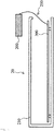
- FIG. 1 is a diagram showing an example of a schematic configuration of a vacuum pump 1 according to an embodiment of the present invention, the diagram showing a cross section of the vacuum pump 1 along an axial direction.
- the vacuum pump 1 is configured by a vacuum pump main body, and a control apparatus (control unit) 20 controlling the vacuum pump main body and including a regenerative resistor 200.
- control apparatus 20 for controlling the vacuum pump main body is attached to the vacuum pump main body via a pump fixing spacer 18.
- the vacuum pump main body and the control apparatus 20 are integrated, with a gap 400 therebetween.
- vacuum pump 1 indicates the vacuum pump main body unless otherwise specified.
- the vacuum pump 1 of the present embodiment is a so-called compound molecular pump having a turbomolecular pump portion and a thread groove pump portion.
- a casing 2 (inlet port-side casing portion) configuring a housing of the vacuum pump 1 has a substantially cylindrical shape and constitutes a case of the vacuum pump 1 together with a base 3 (outlet port-side casing portion) provided in a lower portion of the casing 2 (outlet port 6 side).
- a gas transfer mechanism which is a structure bringing about an exhaust function of the vacuum pump main body, is stored in the case of the vacuum pump 1.
- This gas transfer mechanism is composed mainly of a rotating portion supported rotatably and a stator portion fixed to the case of the vacuum pump 1.
- An inlet port 4 for introducing gas into the vacuum pump 1 is formed at an end portion of the casing 2.
- a flange portion 5 protruding toward an outer periphery of the casing 2 is formed on an end surface of the casing 2 at the inlet port 4 side.
- the outlet port 6 for exhausting the gas from the vacuum pump 1 is formed in the base 3.
- a cooling (water-cooling) pipe composed of a tube (pipe)-like member is embedded in the base 3 for the purpose of reducing the impact of heat that the control apparatus 20 receives from the vacuum pump 1.
- This cooling pipe is a member configured to cool the periphery thereof by allowing a coolant, which is a heat medium, to flow therein and causing this coolant to absorb the heat.
- a member with low thermal resistance i.e., a member with high thermal conductivity, such as copper or stainless steel
- the coolant flowing through the cooling pipe may be in the form of liquid or gas.
- the coolant is a gas, ammonia, methane, ethane, halogen, helium, carbon dioxide, air or the like, for example, can be used.
- the rotating portion includes a shaft 7 which is a rotating shaft, a rotor 8 disposed on the shaft 7, rotor blades 9 provided on the rotor 8, and a stator column 10 provided on the outlet port 6 side (thread groove pump portion). Note that the shaft 7 and the rotor 8 constitute a rotor portion.
- the rotor blades 9 are formed of blades extending radially from the shaft 7 at a predetermined angle from a plane perpendicular to an axis of the shaft 7.
- the stator column 10 is formed of a cylindrical member having a cylindrical shape which is concentric with a rotation axis of the rotor 8.
- a motor portion 11 for rotating the shaft 7 at high speeds is provided in the middle of the shaft 7 in the axial direction thereof.
- Radial magnetic bearing devices 12, 13 for supporting the shaft 7 in a radial direction in a non-contact manner are provided on the inlet port 4 side and the outlet port 6 side respectively, with respect to the motor portion 11 of the shaft 7, and axial magnetic bearing devices 14 for supporting the shaft 7 in the axial direction in a non-contact manner are provided at a lower end of the shaft 7.
- a stator portion is formed on an inner periphery side of the case of the vacuum pump 1.
- the stator portion is composed of stator blades 15 provided on the inlet port 4 side (turbomolecular pump portion), a thread groove spacer 16 provided on an inner peripheral surface of the casing 2, and the like.
- the stator blades 15 are formed of blades extending from an inner peripheral surface of the case of the vacuum pump 1 toward the shaft 7, at a predetermined angle from a plane perpendicular to the axis of the shaft 7.
- stator blades 15 in respective stages are separated by cylindrical spacers 17.
- stator blades 15 are formed in a plurality of stages alternately with the rotor blades 9 along the axial direction.
- Spiral grooves are formed on a surface of the thread groove spacer 16 that faces the stator column 10.
- the thread groove spacer 16 faces an outer peripheral surface of the stator column 10, with a predetermined clearance (space) therebetween.
- the direction of the spiral grooves formed in the thread groove spacer 16 is the direction toward the outlet port 6 when a gas is transported through the spiral grooves in the direction of rotation of the rotor 8.
- the depth of the spiral grooves is adapted to become shallower toward the outlet port 6, and therefore the gas transported through the spiral grooves is configured to be compressed as the gas approaches the outlet port 6.
- the vacuum pump 1 configured as described above performs vacuum exhaust processing in a vacuum chamber (not shown) disposed in the vacuum pump 1.
- the vacuum chamber is a vacuum device used as, for example, a chamber or the like of a surface analyzer or a microfabrication apparatus.
- FIG. 2 is a diagram showing an example of a schematic configuration of the control apparatus 20 according to the present embodiment.
- the control apparatus 20 is a control unit having a control circuit for controlling various operations performed in the vacuum pump 1, and is disposed in (attached to) a bottom portion of the base 3 of the vacuum pump 1 via the pump fixing spacer 18, as shown in FIG. 1 .
- the control apparatus 20 of the present embodiment is provided with a connector (not shown) paired with a connector provided in the vacuum pump 1 (not shown), and the control circuit provided in the control apparatus 20 is configured to be electrically connected to electronic components of the vacuum pump 1 by joining (coupling) the connector of the vacuum pump 1 and the connector of the control apparatus 20 to each other. Therefore, the control apparatus 20 can supply drive signals and power of the motor portion 11, the radial magnetic bearing devices 12, 13, the axial magnetic bearing devices 14, and a displacement sensor (not shown) of the vacuum pump 1 to the vacuum pump 1 and receive various signals from the vacuum pump 1 without using a dedicated cable for connecting the vacuum pump 1 and the control apparatus 20.
- the control apparatus 20 includes a case 210, a regenerative resistor 200, a conducting wire 250, and a control board 300.
- the case 210 (control board portion casing) is a housing of the control apparatus 20 that is configured by aluminum die casting and has the control board 300 fixed inside the case 210.
- the regenerative resistor 200 is a component for treating regenerative energy (electric energy) generated when the vacuum pump 1 decelerates, converts this regenerative energy into thermal energy and consumes the resultant thermal energy.
- the present embodiment explains an example in which two equivalent regenerative resistors 200 are disposed (one of them is not shown in FIG. 2 ).
- the number of regenerative resistors 200 to be disposed can be set accordingly depending on the costs and the like.
- the control board 300 is a board on which the control circuit for controlling the vacuum pump 1 is mounted (motor drive unit), and in the present embodiment a plurality of the control boards 300 are fixed inside the case 210.
- the control circuit mounted on each of the control boards 300 is provided with drive circuits, power circuits and the like of the motor portion 11, the radial magnetic bearing devices 12, 13, and the axial magnetic bearing devices 14 of the vacuum pump 1.
- a circuit for controlling these drive circuits, and a storage element containing various information used in controlling the vacuum pump 1 are mounted on each of the control boards 300.
- Environmental temperatures taking reliability into consideration are typically set in electronic components (elements) used in electronic circuits.
- the storage element described above is a low heat-resistant element having heat-resistant characteristics in which the set environmental temperature is approximately 60°C. Note that, during the operation of the vacuum pump 1, each of the electrical components must be used within a set range of environmental temperatures. Also, in addition to the low heat-resistant element, many components (power devices) that generate heat by loss occurring in the element (internal loss) are used as the circuits provided inside the control apparatus 20. Examples of such components include transistor elements constituting an inverter circuit which is the drive circuit of the motor portion 11. Environmental temperatures are also set for such elements that produce high amounts of self-heat.
- the regenerative resistor 200 according to the present embodiment is attached to the control board 300 by the conducting wire 250.
- the conducting wire 250 is long enough to reach the base 3 of the vacuum pump 1 disposed in an upper part of the control apparatus 20 and connects the regenerative resistor 200 and the control board 300 to each other.
- the regenerative resistor 200 that is at least partially connected to the control board 300 by the conducting wire 250 is separated from the control apparatus 20 itself, embedded in the base 3 of the vacuum pump 1, and fixed to the base 3 using a screw or the like ( FIG. 1 ).
- the regenerative resistor 200 is separated from the control apparatus 20 without being installed in the control apparatus 20, and installed in (fixed to) the base 3 of the vacuum pump 1.
- the heat dissipation capability of the regenerative resistor 200 can be improved with a simple configuration.
- the regenerative resistor 200 can also be cooled by the cooling device disposed in the vacuum pump 1. Since a cooling device for the control apparatus 20 no longer needs to be provided, reduction in size of the control apparatus 20 and the vacuum pump 1 having the control apparatus 20 can be realized.
- the present embodiment has described an example in which the regenerative resistor 200 is provided in the base 3 in which the outlet port is disposed, but the present invention is not limited to this configuration. If there exists a section where a housing other than the casing 2 or the base 3 is formed, the regenerative resistor 200 may be disposed in this section.
- control apparatus 20 is disposed at the bottom portion of the base 3 of the vacuum pump 1, but the present invention is not limited to this configuration.
- control apparatus 20 may be disposed on a side surface of the base 3.
- the gap 400 according to the present embodiment is described next with reference to FIG. 1 .
- the gap 400 is further provided between the vacuum pump 1 (base 3) and the control apparatus 20.
- the gap 400 is provided between the vacuum pump 1 and the control apparatus 20 to insulate them with air, so that the heat of the regenerative resistor 200 is not transmitted to the control apparatus 20 through the base 3.
- the gap 400 is desirably approximately 0.1 mm to 10 mm in accordance with the setting of each component.
- the gap 400 can be provided by, for example, raising the pump fixing spacer 18 by approximately 2 mm.
- the pump fixing spacer 18 is desirably manufactured with a material having poor heat conduction (such as iron). Therefore, conduction of the heat of the regenerative resistor 200 from the base 3 to the control apparatus 20 can be reduced more effectively.
- the regenerative resistor 200 is preferably configured to be held (stored) in the base 3 with no gap therebetween (so as to stick to the base 3 tightly), in view of the expansion width of the regenerative resistor 200.
- the pump fixing spacer 18 is provided between the base 3 of the vacuum pump 1 provided with the regenerative resistor 200 separated from the control apparatus 20, and the control apparatus 20.
- the weight of the vacuum pump 1 imposed on the control apparatus 20 can be released, whereby the load on the control apparatus 20 caused by the weight of the vacuum pump 1 can be reduced.
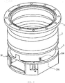
- FIG. 3 is a diagram showing an example of a configuration in which the regenerative resistor 200 (control apparatus 20) according to the present embodiment is disposed on the base 3.
- a hollow portion capable of storing the regenerative resistor 200 is provided in an outer portion of the base 3, and the regenerative resistor 200 is inserted into this hollow portion and secured thereto with a screw.
- the regenerative resistor 200 and the base 3 are in close contact with each other, the regenerative resistor 200 can also be cooled by a cooling device (not shown) for cooling the base 3.
- the outer covering body (cover) disposed in the part where the regenerative resistor 200 is disposed is described next.
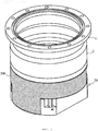
- FIG. 4 is a diagram showing an example of a configuration in which the part where the regenerative resistor 200 of the present embodiment is disposed is covered with a cover 500.
- the part of the base 3 where the regenerative resistor 200 is disposed is covered with the cover 500.
- Such a configuration can cut off electrical noises that can be generated due to long wiring when the regenerative resistor 200 is disposed outside the control apparatus 20 (control board 300). Such a configuration can also insulate a charged portion that is exposed by separately placing the regenerative resistor 200.
- separately placing (storing) the regenerative resistor 200 can lead to lowering of an indirect surface temperature of the base 3 which can become high. As a result, for example, the safety for a worker who performs inspection and touches the base 3 can be improved.
- the present embodiment has the configuration in which the entire part where the regenerative resistor 200 is disposed is covered with the cover 500, but the present invention is not limited to this configuration.
- the shape and size of the cover 500 can be changed accordingly as long as at least the regenerative resistor 200 and the conducting wire 250 (the part connecting the regenerative resistor 200 and the control board 300) are covered.
- cover 500 is desirably made of a material having poor heat conduction such as stainless steel (SUS).
- a gap of approximately 1 mm is provided between the control apparatus 20 and the base 3.
- the present embodiment can achieve the following effects.
- the regenerative resistor 200 is disposed on the base 3 of the vacuum pump 1 from the perspective of being a temperature-controlled component, the place where the regenerative resistor 200 is placed separately is not necessarily limited to the base 3 of the vacuum pump 1. Depending on the specification of the vacuum pump 1 or the situation in which the vacuum pump 1 is disposed, the regenerative resistor 200 may be disposed in any other component of the vacuum pump 1 as long as the component has a large heat capacity.
- the gap 400 is provided between the base 3 of the vacuum pump 1 on which the regenerative resistor 200 is provided and the control apparatus 20, the present invention is not limited to this configuration.
- a heat insulating material may be provided together with or in place of the gap 400.
- the regenerative resistor 200 may be placed in a metal case specially made for a regenerative resistor, and then this metal case may be inserted (stored) into a regenerative resistor casing (hollow portion).
- the metal case is desirably made of heat-resistant steel or stainless steel (SUS).
Landscapes
- Engineering & Computer Science (AREA)
- Mechanical Engineering (AREA)
- General Engineering & Computer Science (AREA)
- Physics & Mathematics (AREA)
- Thermal Sciences (AREA)
- Non-Positive Displacement Air Blowers (AREA)
- Compressors, Vaccum Pumps And Other Relevant Systems (AREA)
Abstract
Description
- The present invention relates to a vacuum pump and a control apparatus associated with the vacuum pump.
- More specifically, the present invention relates to a vacuum pump provided with a control apparatus having a regenerative resistor, and a control apparatus associated with the vacuum pump.
- A vacuum pump such as a turbomolecular pump that exhausts by rotating a rotor thereof at high speeds in a casing having an inlet port and an outlet port typically has a control apparatus (controller) connected electrically thereto, the control apparatus controlling a motor for rotating the rotor.
- In a rotary machine using such a motor, rotation of the motor at deceleration of the rotary machine produces electric energy (regenerative energy). This regenerative energy triggers an increase in DC voltage in a motor driver circuit controlling the motor, which may lead to a malfunction of in-circuit elements. For this reason, the regenerative energy needs to be treated/consumed properly.
- A regenerative resistor can be named as one of the methods for treating the regenerative energy.
- The regenerative resistor is a resistor that converts the regenerative energy into thermal energy and consumes the resultant thermal energy. Because short wires have conventionally been used as such regenerative resistors, as described in Japanese Patent Application Publication No.
H07-279962 2002-180990 2004-112877 - However, with the regenerative resistor being installed in the control apparatus, the heat of the regenerative resistor easily becomes locked up in the control apparatus and therefore cannot easily be dissipated. Even if the heat is dissipated, a temperature rise of the control apparatus is drastic due to a small heat capacity of the control apparatus. Since the generation of heat of the regenerative resistor is inevitable, from the standpoint of safety and reliability, the regenerative resistor itself needs to be constantly cooled in order to keep the temperature of the control apparatus significantly lower than the tolerance of the regenerative resistor.
- Examples of the method for cooling the regenerative resistor include preparing a heatsink (radiator, radiator plate) separately and attaching the heatsink in the vicinity of the control apparatus installed with the regenerative resistor generating heat, to dissipate the heat of the regenerative resistor and to thereby reduce the temperature of the control apparatus.
- Alternatively, another method is to attach an air-cooling fan (cooling fan) or the like to the control apparatus to enhance the coolability by forcibly increasing the airflow.
- Yet another method is to connect a water-cooled plate to the control apparatus, the water-cooled plate having a water-cooling pipe embedded circumferentially, and let a coolant flow into the cooling pipe so that the water-cooled plate is cooled, thereby forcibly cooling the control apparatus in contact with the cooling plate and the regenerative resistor installed in the control apparatus.
- However, in a vacuum pump, it is difficult to separately provide the heatsink because the size of the vacuum pump is usually small in relation to the power of the motor and the environment around the vacuum pump needs to be cleaned in connection with the steps of a vacuum device. Moreover, given noise, reliability and the like, in some cases the fan cannot be provided.
- Further, when providing the cooling device separately, a special cooling pipe or cooling system is required, which may not only lead to a cost increase but also bring out the need to secure space for disposing such cooling member.
- Thus, one of the difficulties in installing the conventional regenerative resistor in a control apparatus is providing a device for cooling the control apparatus. It is also difficult to downsize a vacuum pump in which the control apparatus is to be disposed, to secure space for disposing the cooling member described above.
- An object of the present invention is to realize a vacuum pump capable of improving the heat dissipation capability of a regenerative resistor with a simple configuration, and a control apparatus associated with such a vacuum pump.
- An invention described in
claim 1 provides a vacuum pump that includes a control apparatus provided with a control board portion equipped with a control circuit for controlling a vacuum pump main body, and a regenerative resistor for treating regenerative energy generated by controlling the vacuum pump main body, wherein the control board portion is disposed inside a control board portion casing which is a casing enclosing the control board portion, and the regenerative resistor is disposed in the vacuum pump main body and connected to the control board portion by a wire. - An invention described in
claim 2 provides the vacuum pump described inclaim 1, wherein the vacuum pump main body has a housing in which an inlet port and an outlet port are formed, the housing is configured with at least an inlet port-side casing portion and an outlet port-side casing portion, and the regenerative resistor is disposed in the outlet port-side casing portion. - An invention described in claim 3 provides the vacuum pump described in
claim 2, wherein the outlet port-side casing portion is controlled to keep a predetermined temperature. - An invention described in
claim 4 provides the vacuum pump described inclaim 2 or 3, wherein the control board portion casing is disposed under the outlet port-side casing portion and integrated with the vacuum pump main body. - An invention described in
claim 5 provides the vacuum pump described in at least any one ofclaims 2 to 4, wherein a predetermined gap for thermal insulation is provided between the outlet port-side casing portion and the control board portion casing. - An invention described in
claim 6 provides the vacuum pump described in at least any one ofclaims 2 to 5, further comprising an outer covering body for covering at least a part of a section of the outlet port-side casing portion in which the regenerative resistor is disposed. - An invention described in
claim 7 provides a control apparatus associated with the vacuum pump described in at least any one ofclaims 1 to 6. - According to the present invention, the heat dissipation capability of a regenerative resistor can be improved with a simple configuration by removing the regenerative resistor from a control board of a control apparatus and disposing the regenerative resistor in a vacuum pump having a relatively large heat capacity.
- According to this configuration, a cooling device for the control apparatus no longer needs to be provided separately, and as a result reduction in size of the control apparatus and the vacuum pump having the control apparatus can be realized.
-
-
FIG. 1 is a diagram showing an example of a schematic configuration of a vacuum pump according to an embodiment of the present invention; -
FIG. 2 is a diagram showing an example of a schematic configuration of a control apparatus having a regenerative resistor according to the embodiment of the present invention; -
FIG. 3 is a diagram showing an example of arranging the vacuum pump and the control apparatus (regenerative resistor) according to the embodiment of the present invention; and -
FIG. 4 is a diagram showing an example of a configuration in which an outer covering body is disposed when arranging the vacuum pump and the control apparatus (regenerative resistor) according to the embodiment of the present invention. - In the present embodiment, a regenerative resistor (regenerative resistor portion of a control apparatus) is removed from a control board (control board portion) of the control apparatus and disposed in a base of a vacuum pump.
- More specifically, the regenerative resistor is detached from a motor drive unit (control apparatus) which is a board on which a control circuit for controlling the vacuum pump is mounted. The detached regenerative resistor is then disposed in the base of the vacuum pump through a wire, the vacuum pump having a large heat capacity.
- Furthermore, a gap is provided between the vacuum pump (base part) and the control apparatus to prevent transmission of heat generated in the regenerative resistor to the control apparatus.
- In addition, in order to reduce/attenuate an electrical noise that is generated by separately placing the regenerative resistor on the base, a cover (an outer covering body) is provided on the regenerative resistor disposed in the base part of the vacuum pump and at least a part of the wire portion.
- According to this configuration, in the present embodiment, the regenerative resistor is separated from the control apparatus (the regenerative resistor is connected by the wire) and provided in the vacuum pump having a large heat capacity (the base part, in the present embodiment). Therefore, a temperature increase of the control apparatus itself can be reduced/attenuated.
- By providing a gap between the base part (i.e., an outlet port-side casing portion) of the vacuum pump where the regenerative resistor is provided and the control apparatus (i.e., a control board portion casing), air for heat insulation fills the gap. As a result, not only is it possible to realize heat insulation by the air, but also a temperature increase of the control apparatus can be reduced/attenuated.
- By providing a cover (outer covering body/harness) in the base part where the regenerative resistor is disposed, an electrical noise generated by stretching the wire for separately placing the regenerative resistor can be reduced/attenuated.
- A preferred embodiment of the present invention is described hereinafter in detail with reference to
FIGS. 1 to 4 . -
FIG. 1 is a diagram showing an example of a schematic configuration of avacuum pump 1 according to an embodiment of the present invention, the diagram showing a cross section of thevacuum pump 1 along an axial direction. - The
vacuum pump 1 according to the present embodiment is configured by a vacuum pump main body, and a control apparatus (control unit) 20 controlling the vacuum pump main body and including aregenerative resistor 200. - In the present embodiment, the
control apparatus 20 for controlling the vacuum pump main body is attached to the vacuum pump main body via apump fixing spacer 18. In other words, the vacuum pump main body and thecontrol apparatus 20 are integrated, with agap 400 therebetween. In the following description of the present embodiment (the configuration of the vacuum pump 1), "vacuum pump 1" indicates the vacuum pump main body unless otherwise specified. - First, the
vacuum pump 1 according to the present embodiment is explained. - The
vacuum pump 1 of the present embodiment is a so-called compound molecular pump having a turbomolecular pump portion and a thread groove pump portion. - A casing 2 (inlet port-side casing portion) configuring a housing of the
vacuum pump 1 has a substantially cylindrical shape and constitutes a case of thevacuum pump 1 together with a base 3 (outlet port-side casing portion) provided in a lower portion of the casing 2 (outlet port 6 side). A gas transfer mechanism, which is a structure bringing about an exhaust function of the vacuum pump main body, is stored in the case of thevacuum pump 1. - This gas transfer mechanism is composed mainly of a rotating portion supported rotatably and a stator portion fixed to the case of the
vacuum pump 1. - An
inlet port 4 for introducing gas into thevacuum pump 1 is formed at an end portion of thecasing 2. Aflange portion 5 protruding toward an outer periphery of thecasing 2 is formed on an end surface of thecasing 2 at theinlet port 4 side. - The
outlet port 6 for exhausting the gas from thevacuum pump 1 is formed in the base 3. - Although not shown, a cooling (water-cooling) pipe composed of a tube (pipe)-like member is embedded in the base 3 for the purpose of reducing the impact of heat that the
control apparatus 20 receives from thevacuum pump 1. Thus, the temperature of the base 3 is controlled. This cooling pipe is a member configured to cool the periphery thereof by allowing a coolant, which is a heat medium, to flow therein and causing this coolant to absorb the heat. - Since the base 3 is forced to cool down by letting the coolant flow into the cooling pipe as described above, the heat conducted from the
vacuum pump 1 to thecontrol apparatus 20 is reduced (attenuated). - Note that a member with low thermal resistance, i.e., a member with high thermal conductivity, such as copper or stainless steel, is used as a material of the cooling pipe. The coolant flowing through the cooling pipe, that is, a material for cooling an object, may be in the form of liquid or gas. Water, a calcium chloride aqueous solution, an ethylene glycol aqueous solution or the like, for example, can be used as the coolant if the coolant is a liquid. On the other hand, if the coolant is a gas, ammonia, methane, ethane, halogen, helium, carbon dioxide, air or the like, for example, can be used.
- The rotating portion includes a
shaft 7 which is a rotating shaft, a rotor 8 disposed on theshaft 7,rotor blades 9 provided on the rotor 8, and astator column 10 provided on theoutlet port 6 side (thread groove pump portion). Note that theshaft 7 and the rotor 8 constitute a rotor portion. - The
rotor blades 9 are formed of blades extending radially from theshaft 7 at a predetermined angle from a plane perpendicular to an axis of theshaft 7. - The
stator column 10 is formed of a cylindrical member having a cylindrical shape which is concentric with a rotation axis of the rotor 8. - A
motor portion 11 for rotating theshaft 7 at high speeds is provided in the middle of theshaft 7 in the axial direction thereof. - Radial
magnetic bearing devices shaft 7 in a radial direction in a non-contact manner are provided on theinlet port 4 side and theoutlet port 6 side respectively, with respect to themotor portion 11 of theshaft 7, and axialmagnetic bearing devices 14 for supporting theshaft 7 in the axial direction in a non-contact manner are provided at a lower end of theshaft 7. - A stator portion is formed on an inner periphery side of the case of the
vacuum pump 1. The stator portion is composed ofstator blades 15 provided on theinlet port 4 side (turbomolecular pump portion), athread groove spacer 16 provided on an inner peripheral surface of thecasing 2, and the like. - The
stator blades 15 are formed of blades extending from an inner peripheral surface of the case of thevacuum pump 1 toward theshaft 7, at a predetermined angle from a plane perpendicular to the axis of theshaft 7. - The
stator blades 15 in respective stages are separated bycylindrical spacers 17. - In the
vacuum pump 1, thestator blades 15 are formed in a plurality of stages alternately with therotor blades 9 along the axial direction. - Spiral grooves are formed on a surface of the
thread groove spacer 16 that faces thestator column 10. Thethread groove spacer 16 faces an outer peripheral surface of thestator column 10, with a predetermined clearance (space) therebetween. The direction of the spiral grooves formed in thethread groove spacer 16 is the direction toward theoutlet port 6 when a gas is transported through the spiral grooves in the direction of rotation of the rotor 8. - The depth of the spiral grooves is adapted to become shallower toward the
outlet port 6, and therefore the gas transported through the spiral grooves is configured to be compressed as the gas approaches theoutlet port 6. - The
vacuum pump 1 configured as described above performs vacuum exhaust processing in a vacuum chamber (not shown) disposed in thevacuum pump 1. The vacuum chamber is a vacuum device used as, for example, a chamber or the like of a surface analyzer or a microfabrication apparatus. - A structure of the
control apparatus 20 attached to thevacuum pump 1 having the foregoing configuration is described next. -
FIG. 2 is a diagram showing an example of a schematic configuration of thecontrol apparatus 20 according to the present embodiment. - The
control apparatus 20 according to the present embodiment is a control unit having a control circuit for controlling various operations performed in thevacuum pump 1, and is disposed in (attached to) a bottom portion of the base 3 of thevacuum pump 1 via thepump fixing spacer 18, as shown inFIG. 1 . - The
control apparatus 20 of the present embodiment is provided with a connector (not shown) paired with a connector provided in the vacuum pump 1 (not shown), and the control circuit provided in thecontrol apparatus 20 is configured to be electrically connected to electronic components of thevacuum pump 1 by joining (coupling) the connector of thevacuum pump 1 and the connector of thecontrol apparatus 20 to each other. Therefore, thecontrol apparatus 20 can supply drive signals and power of themotor portion 11, the radialmagnetic bearing devices magnetic bearing devices 14, and a displacement sensor (not shown) of thevacuum pump 1 to thevacuum pump 1 and receive various signals from thevacuum pump 1 without using a dedicated cable for connecting thevacuum pump 1 and thecontrol apparatus 20. - The
control apparatus 20 according to the present embodiment includes acase 210, aregenerative resistor 200, aconducting wire 250, and acontrol board 300. - The case 210 (control board portion casing) is a housing of the
control apparatus 20 that is configured by aluminum die casting and has thecontrol board 300 fixed inside thecase 210. - The
regenerative resistor 200 is a component for treating regenerative energy (electric energy) generated when thevacuum pump 1 decelerates, converts this regenerative energy into thermal energy and consumes the resultant thermal energy. - The present embodiment explains an example in which two equivalent
regenerative resistors 200 are disposed (one of them is not shown inFIG. 2 ). The number ofregenerative resistors 200 to be disposed can be set accordingly depending on the costs and the like. - The
control board 300 is a board on which the control circuit for controlling thevacuum pump 1 is mounted (motor drive unit), and in the present embodiment a plurality of thecontrol boards 300 are fixed inside thecase 210. The control circuit mounted on each of thecontrol boards 300 is provided with drive circuits, power circuits and the like of themotor portion 11, the radialmagnetic bearing devices magnetic bearing devices 14 of thevacuum pump 1. In addition, a circuit for controlling these drive circuits, and a storage element containing various information used in controlling thevacuum pump 1, are mounted on each of thecontrol boards 300. - Environmental temperatures taking reliability into consideration are typically set in electronic components (elements) used in electronic circuits. The storage element described above is a low heat-resistant element having heat-resistant characteristics in which the set environmental temperature is approximately 60°C. Note that, during the operation of the
vacuum pump 1, each of the electrical components must be used within a set range of environmental temperatures. Also, in addition to the low heat-resistant element, many components (power devices) that generate heat by loss occurring in the element (internal loss) are used as the circuits provided inside thecontrol apparatus 20. Examples of such components include transistor elements constituting an inverter circuit which is the drive circuit of themotor portion 11. Environmental temperatures are also set for such elements that produce high amounts of self-heat. - The
regenerative resistor 200 according to the present embodiment is attached to thecontrol board 300 by theconducting wire 250. - The
conducting wire 250 is long enough to reach the base 3 of thevacuum pump 1 disposed in an upper part of thecontrol apparatus 20 and connects theregenerative resistor 200 and thecontrol board 300 to each other. - The
regenerative resistor 200 that is at least partially connected to thecontrol board 300 by theconducting wire 250 is separated from thecontrol apparatus 20 itself, embedded in the base 3 of thevacuum pump 1, and fixed to the base 3 using a screw or the like (FIG. 1 ). - In the present embodiment, the
regenerative resistor 200 is separated from thecontrol apparatus 20 without being installed in thecontrol apparatus 20, and installed in (fixed to) the base 3 of thevacuum pump 1. - By disposing the
regenerative resistor 200 in the base 3 of thevacuum pump 1 having a relatively large heat capacity, the heat dissipation capability of theregenerative resistor 200 can be improved with a simple configuration. - The
regenerative resistor 200 can also be cooled by the cooling device disposed in thevacuum pump 1. Since a cooling device for thecontrol apparatus 20 no longer needs to be provided, reduction in size of thecontrol apparatus 20 and thevacuum pump 1 having thecontrol apparatus 20 can be realized. - The present embodiment has described an example in which the
regenerative resistor 200 is provided in the base 3 in which the outlet port is disposed, but the present invention is not limited to this configuration. If there exists a section where a housing other than thecasing 2 or the base 3 is formed, theregenerative resistor 200 may be disposed in this section. - The present embodiment has described an example in which the
control apparatus 20 is disposed at the bottom portion of the base 3 of thevacuum pump 1, but the present invention is not limited to this configuration. For example, thecontrol apparatus 20 may be disposed on a side surface of the base 3. - The
gap 400 according to the present embodiment is described next with reference toFIG. 1 . - In the present embodiment, when separating the
regenerative resistor 200 from thecontrol apparatus 20 in the foregoing configuration, thegap 400 is further provided between the vacuum pump 1 (base 3) and thecontrol apparatus 20. - Because the temperature of the base 3 of the
vacuum pump 1 in which theregenerative resistor 200 is disposed increases as theregenerative resistor 200 generates heat, thegap 400 is provided between thevacuum pump 1 and thecontrol apparatus 20 to insulate them with air, so that the heat of theregenerative resistor 200 is not transmitted to thecontrol apparatus 20 through the base 3. Thegap 400 is desirably approximately 0.1 mm to 10 mm in accordance with the setting of each component. - The
gap 400 can be provided by, for example, raising thepump fixing spacer 18 by approximately 2 mm. - The
pump fixing spacer 18 is desirably manufactured with a material having poor heat conduction (such as iron). Therefore, conduction of the heat of theregenerative resistor 200 from the base 3 to thecontrol apparatus 20 can be reduced more effectively. - It is preferred that a gap not be provided between the base 3 and the
regenerative resistor 200, in order to allow the base 3 to effectively absorb the heat of theregenerative resistor 200. However, since theregenerative resistor 200 expands as it generates heat, theregenerative resistor 200 is preferably configured to be held (stored) in the base 3 with no gap therebetween (so as to stick to the base 3 tightly), in view of the expansion width of theregenerative resistor 200. - In the present embodiment, the
pump fixing spacer 18 is provided between the base 3 of thevacuum pump 1 provided with theregenerative resistor 200 separated from thecontrol apparatus 20, and thecontrol apparatus 20. - According to this configuration, by providing the
gap 400 between the vacuum pump 1 (base 3) and thecontrol apparatus 20, insulation using air can be realized, further improving the heat dissipation capability of theregenerative resistor 200. - With the
gap 400 provided therebetween, the weight of thevacuum pump 1 imposed on thecontrol apparatus 20 can be released, whereby the load on thecontrol apparatus 20 caused by the weight of thevacuum pump 1 can be reduced. -
FIG. 3 is a diagram showing an example of a configuration in which the regenerative resistor 200 (control apparatus 20) according to the present embodiment is disposed on the base 3. - In the present embodiment, in order to insert (store) the
regenerative resistor 200 in the base 3, a hollow portion capable of storing theregenerative resistor 200 is provided in an outer portion of the base 3, and theregenerative resistor 200 is inserted into this hollow portion and secured thereto with a screw. - In the present embodiment, because the
regenerative resistor 200 and the base 3 are in close contact with each other, theregenerative resistor 200 can also be cooled by a cooling device (not shown) for cooling the base 3. - The outer covering body (cover) disposed in the part where the
regenerative resistor 200 is disposed is described next. -
FIG. 4 is a diagram showing an example of a configuration in which the part where theregenerative resistor 200 of the present embodiment is disposed is covered with acover 500. - As shown in
FIG. 4 , in the present embodiment, the part of the base 3 where theregenerative resistor 200 is disposed is covered with thecover 500. - Such a configuration can cut off electrical noises that can be generated due to long wiring when the
regenerative resistor 200 is disposed outside the control apparatus 20 (control board 300). Such a configuration can also insulate a charged portion that is exposed by separately placing theregenerative resistor 200. - Furthermore, separately placing (storing) the
regenerative resistor 200 can lead to lowering of an indirect surface temperature of the base 3 which can become high. As a result, for example, the safety for a worker who performs inspection and touches the base 3 can be improved. - The present embodiment has the configuration in which the entire part where the
regenerative resistor 200 is disposed is covered with thecover 500, but the present invention is not limited to this configuration. The shape and size of thecover 500 can be changed accordingly as long as at least theregenerative resistor 200 and the conducting wire 250 (the part connecting theregenerative resistor 200 and the control board 300) are covered. - Note that the
cover 500 is desirably made of a material having poor heat conduction such as stainless steel (SUS). - In the present embodiment, even when the
cover 500 is provided on the base 3, a gap of approximately 1 mm (gap 400) is provided between thecontrol apparatus 20 and the base 3. - According to the configurations described above, the present embodiment can achieve the following effects.
- (1) By treating the heat emitted from the
regenerative resistor 200 by means of the base 3 having a large heat capacity, a temperature increase of thecontrol apparatus 20 can be reduced (attenuated).
Specifically, not only is it possible to improve the heat dissipation capability of theregenerative resistor 200 with a simple configuration, but also thecontrol apparatus 20 capable of appropriately reducing/attenuating a temperature increase thereof and thevacuum pump 1 having thecontrol apparatus 20 can be provided. - (2) By installing the
control apparatus 20 and the base 3 at positions separated by a predetermined clearance (gap 400), a temperature increase of thecontrol apparatus 20 and the heavy load of thevacuum pump 1 can be reduced. - (3) Due to the configuration in which the
cover 500 is provided, the following issues (a) and (b) that can be caused by separately placing theregenerative resistor 200 can be reduced.- (a) Electrical noises that can be generated due to long wiring can be cut off.
- (b) Disposing the
regenerative resistor 200 can lead to lowering of an indirect surface temperature of the base 3 which can become high.
- In the present embodiment, although the
regenerative resistor 200 is disposed on the base 3 of thevacuum pump 1 from the perspective of being a temperature-controlled component, the place where theregenerative resistor 200 is placed separately is not necessarily limited to the base 3 of thevacuum pump 1. Depending on the specification of thevacuum pump 1 or the situation in which thevacuum pump 1 is disposed, theregenerative resistor 200 may be disposed in any other component of thevacuum pump 1 as long as the component has a large heat capacity. - Although, in the present embodiment, the
gap 400 is provided between the base 3 of thevacuum pump 1 on which theregenerative resistor 200 is provided and thecontrol apparatus 20, the present invention is not limited to this configuration. For example, a heat insulating material may be provided together with or in place of thegap 400. - Note that various shapes and sizes can be adopted for the
regenerative resistor 200. - In order to cope with the differences between such shapes and sizes and non-smoothness of the surface, instead of inserting the
regenerative resistor 200 directly into the base 3 of thevacuum pump 1, theregenerative resistor 200 may be placed in a metal case specially made for a regenerative resistor, and then this metal case may be inserted (stored) into a regenerative resistor casing (hollow portion). In this case, the metal case is desirably made of heat-resistant steel or stainless steel (SUS). - Note that the embodiment of the present invention and each modification thereof may be combined as needed.
- Various modifications can be made to the present invention without departing from the spirit of the present invention, and it goes without saying that the present invention extends to such modifications.
-
- 1
- Vacuum pump
- 2
- Casing
- 3
- Base
- 4
- Inlet port
- 5
- Flange portion
- 6
- Outlet port
- 7
- Shaft
- 8
- Rotor
- 9
- Rotor blade
- 10
- Stator column
- 11
- Motor portion
- 12, 13
- Radial magnetic bearing device
- 14
- Axial magnetic bearing device
- 15
- Stator blade
- 16
- Thread groove spacer
- 17
- Spacer
- 18
- Pump fixing spacer
- 20
- Control apparatus (control unit)
- 200
- Regenerative resistor
- 210
- Case
- 250
- Conducting wire
- 300
- Control board
- 400
- Gap
- 500
- Cover
Claims (7)
- A vacuum pump, comprising:a control apparatus provided with a control board portion equipped with a control circuit for controlling a vacuum pump main body; anda regenerative resistor for treating regenerative energy generated by controlling the vacuum pump main body,wherein the control board portion is disposed inside a control board portion casing which is a casing enclosing the control board portion, andthe regenerative resistor is disposed in the vacuum pump main body and connected to the control board portion by a wire.
- The vacuum pump according to claim 1, wherein
the vacuum pump main body has a housing in which an inlet port and an outlet port are formed,
the housing is configured with at least an inlet port-side casing portion and an outlet port-side casing portion, and
the regenerative resistor is disposed in the outlet port-side casing portion. - The vacuum pump according to claim 2, wherein the outlet port-side casing portion is controlled to keep a predetermined temperature.
- The vacuum pump according to claim 2 or 3, wherein the control board portion casing is disposed under the outlet port-side casing portion and integrated with the vacuum pump main body.
- The vacuum pump according to any one of claims 2 to 4, wherein a predetermined gap for thermal insulation is provided between the outlet port-side casing portion and the control board portion casing.
- The vacuum pump according to any one of claims 2 to 5, further comprising an outer covering body for covering at least a part of a section of the outlet port-side casing portion in which the regenerative resistor is disposed.
- A control apparatus associated with the vacuum pump according to any one of claims 1 to 6.
Applications Claiming Priority (2)
| Application Number | Priority Date | Filing Date | Title |
|---|---|---|---|
| JP2016244436A JP6934298B2 (en) | 2016-12-16 | 2016-12-16 | Vacuum pumps and control devices for vacuum pumps |
| PCT/JP2017/044245 WO2018110466A1 (en) | 2016-12-16 | 2017-12-08 | Vacuum pump and control device provided to vacuum pump |
Publications (3)
| Publication Number | Publication Date |
|---|---|
| EP3557070A1 true EP3557070A1 (en) | 2019-10-23 |
| EP3557070A4 EP3557070A4 (en) | 2020-07-29 |
| EP3557070B1 EP3557070B1 (en) | 2024-04-03 |
Family
ID=62558665
Family Applications (1)
| Application Number | Title | Priority Date | Filing Date |
|---|---|---|---|
| EP17880309.4A Active EP3557070B1 (en) | 2016-12-16 | 2017-12-08 | Vacuum pump and control device provided to vacuum pump |
Country Status (6)
| Country | Link |
|---|---|
| US (1) | US11333153B2 (en) |
| EP (1) | EP3557070B1 (en) |
| JP (1) | JP6934298B2 (en) |
| KR (1) | KR102459715B1 (en) |
| CN (1) | CN110023629A (en) |
| WO (1) | WO2018110466A1 (en) |
Families Citing this family (5)
| Publication number | Priority date | Publication date | Assignee | Title |
|---|---|---|---|---|
| JP7022265B2 (en) * | 2017-10-25 | 2022-02-18 | 株式会社島津製作所 | Vacuum pump |
| JP7087418B2 (en) * | 2018-02-02 | 2022-06-21 | 株式会社島津製作所 | Vacuum pump |
| JP7244328B2 (en) * | 2019-03-28 | 2023-03-22 | エドワーズ株式会社 | Vacuum pump and controller for said vacuum pump |
| JP7294119B2 (en) * | 2019-12-24 | 2023-06-20 | 株式会社島津製作所 | Vacuum pump |
| JP7533324B2 (en) * | 2021-04-01 | 2024-08-14 | 株式会社島津製作所 | Vacuum pump |
Family Cites Families (11)
| Publication number | Priority date | Publication date | Assignee | Title |
|---|---|---|---|---|
| JP3585950B2 (en) | 1994-04-13 | 2004-11-10 | Bocエドワーズ株式会社 | Magnetic bearing type rotating device |
| FR2747431B1 (en) * | 1996-04-15 | 1998-07-03 | Soc D Mecanique Magnetique | TURBOMOLECULAR PUMP WITH ACTIVE MAGNETIC BEARINGS |
| JP2002180990A (en) | 2000-12-11 | 2002-06-26 | Ebara Corp | Vacuum pump controller |
| JP3772979B2 (en) | 2002-09-13 | 2006-05-10 | 株式会社荏原製作所 | Braking control device for rotating machine |
| DE102006041183A1 (en) * | 2006-09-01 | 2008-03-06 | Oerlikon Leybold Vacuum Gmbh | Turbo-molecular vacuum pump, has motor coils connected with brake resistor by change-over contact of brake relay e.g. mechanical relay, and with inverter module by another change-over contact of brake relay |
| JP5156640B2 (en) | 2006-11-22 | 2013-03-06 | エドワーズ株式会社 | Vacuum pump |
| JP5218220B2 (en) * | 2009-03-31 | 2013-06-26 | 株式会社島津製作所 | Turbo molecular pump device and control device thereof |
| JP2012017672A (en) * | 2010-07-07 | 2012-01-26 | Shimadzu Corp | Vacuum pump |
| WO2012046495A1 (en) * | 2010-10-07 | 2012-04-12 | エドワーズ株式会社 | Vacuum pump control device and vacuum pump |
| WO2012053270A1 (en) | 2010-10-19 | 2012-04-26 | エドワーズ株式会社 | Vacuum pump |
| JP5790458B2 (en) * | 2011-12-07 | 2015-10-07 | 株式会社島津製作所 | Turbo molecular pump |
-
2016
- 2016-12-16 JP JP2016244436A patent/JP6934298B2/en active Active
-
2017
- 2017-12-08 EP EP17880309.4A patent/EP3557070B1/en active Active
- 2017-12-08 WO PCT/JP2017/044245 patent/WO2018110466A1/en not_active Ceased
- 2017-12-08 KR KR1020197014721A patent/KR102459715B1/en active Active
- 2017-12-08 US US16/467,416 patent/US11333153B2/en active Active
- 2017-12-08 CN CN201780074547.8A patent/CN110023629A/en active Pending
Also Published As
| Publication number | Publication date |
|---|---|
| EP3557070B1 (en) | 2024-04-03 |
| CN110023629A (en) | 2019-07-16 |
| JP2018096346A (en) | 2018-06-21 |
| JP6934298B2 (en) | 2021-09-15 |
| WO2018110466A1 (en) | 2018-06-21 |
| US20190309760A1 (en) | 2019-10-10 |
| US11333153B2 (en) | 2022-05-17 |
| KR102459715B1 (en) | 2022-10-27 |
| EP3557070A4 (en) | 2020-07-29 |
| KR20190095263A (en) | 2019-08-14 |
Similar Documents
| Publication | Publication Date | Title |
|---|---|---|
| US11333153B2 (en) | Vacuum pump and control apparatus associated with vacuum pump | |
| US10215191B2 (en) | Vacuum pump control device and vacuum pump | |
| US8628309B2 (en) | Turbomolecular pump device and controlling device thereof | |
| EP2482428B1 (en) | Electric rotary machine assembly | |
| JP5156640B2 (en) | Vacuum pump | |
| US20120321442A1 (en) | Turbomolecular pump device | |
| JP7022265B2 (en) | Vacuum pump | |
| US11821440B2 (en) | Vacuum pump, and control device of vacuum pump | |
| US9570962B2 (en) | Controller-integrated rotating electrical machine | |
| CN108506225B (en) | Power integrated vacuum pump | |
| CN104734423B (en) | Motor | |
| CN210660570U (en) | pump unit | |
| WO2019159854A1 (en) | Vacuum pump and vacuum pump control device | |
| CN101965459A (en) | Electric fan | |
| CN108475966A (en) | Fan motor | |
| EP2991107B1 (en) | Heat exchanger device in directed flow system | |
| JP2005054730A (en) | Feed water device of cabinet type |
Legal Events
| Date | Code | Title | Description |
|---|---|---|---|
| STAA | Information on the status of an ep patent application or granted ep patent |
Free format text: STATUS: THE INTERNATIONAL PUBLICATION HAS BEEN MADE |
|
| PUAI | Public reference made under article 153(3) epc to a published international application that has entered the european phase |
Free format text: ORIGINAL CODE: 0009012 |
|
| STAA | Information on the status of an ep patent application or granted ep patent |
Free format text: STATUS: REQUEST FOR EXAMINATION WAS MADE |
|
| 17P | Request for examination filed |
Effective date: 20190610 |
|
| AK | Designated contracting states |
Kind code of ref document: A1 Designated state(s): AL AT BE BG CH CY CZ DE DK EE ES FI FR GB GR HR HU IE IS IT LI LT LU LV MC MK MT NL NO PL PT RO RS SE SI SK SM TR |
|
| A4 | Supplementary search report drawn up and despatched |
Effective date: 20200630 |
|
| RIC1 | Information provided on ipc code assigned before grant |
Ipc: F04D 29/58 20060101ALI20200624BHEP Ipc: F04D 25/06 20060101ALI20200624BHEP Ipc: F04D 19/04 20060101AFI20200624BHEP |
|
| STAA | Information on the status of an ep patent application or granted ep patent |
Free format text: STATUS: EXAMINATION IS IN PROGRESS |
|
| 17Q | First examination report despatched |
Effective date: 20220103 |
|
| GRAP | Despatch of communication of intention to grant a patent |
Free format text: ORIGINAL CODE: EPIDOSNIGR1 |
|
| STAA | Information on the status of an ep patent application or granted ep patent |
Free format text: STATUS: GRANT OF PATENT IS INTENDED |
|
| INTG | Intention to grant announced |
Effective date: 20231115 |
|
| GRAS | Grant fee paid |
Free format text: ORIGINAL CODE: EPIDOSNIGR3 |
|
| GRAA | (expected) grant |
Free format text: ORIGINAL CODE: 0009210 |
|
| STAA | Information on the status of an ep patent application or granted ep patent |
Free format text: STATUS: THE PATENT HAS BEEN GRANTED |
|
| AK | Designated contracting states |
Kind code of ref document: B1 Designated state(s): AL AT BE BG CH CY CZ DE DK EE ES FI FR GB GR HR HU IE IS IT LI LT LU LV MC MK MT NL NO PL PT RO RS SE SI SK SM TR |
|
| REG | Reference to a national code |
Ref country code: GB Ref legal event code: FG4D |
|
| P01 | Opt-out of the competence of the unified patent court (upc) registered |
Effective date: 20240304 |
|
| REG | Reference to a national code |
Ref country code: CH Ref legal event code: EP |
|
| REG | Reference to a national code |
Ref country code: IE Ref legal event code: FG4D |
|
| REG | Reference to a national code |
Ref country code: DE Ref legal event code: R096 Ref document number: 602017080705 Country of ref document: DE |
|
| REG | Reference to a national code |
Ref country code: NL Ref legal event code: FP |
|
| REG | Reference to a national code |
Ref country code: LT Ref legal event code: MG9D |
|
| REG | Reference to a national code |
Ref country code: AT Ref legal event code: MK05 Ref document number: 1672600 Country of ref document: AT Kind code of ref document: T Effective date: 20240403 |
|
| PG25 | Lapsed in a contracting state [announced via postgrant information from national office to epo] |
Ref country code: IS Free format text: LAPSE BECAUSE OF FAILURE TO SUBMIT A TRANSLATION OF THE DESCRIPTION OR TO PAY THE FEE WITHIN THE PRESCRIBED TIME-LIMIT Effective date: 20240803 |
|
| PG25 | Lapsed in a contracting state [announced via postgrant information from national office to epo] |
Ref country code: BG Free format text: LAPSE BECAUSE OF FAILURE TO SUBMIT A TRANSLATION OF THE DESCRIPTION OR TO PAY THE FEE WITHIN THE PRESCRIBED TIME-LIMIT Effective date: 20240403 |
|
| PG25 | Lapsed in a contracting state [announced via postgrant information from national office to epo] |
Ref country code: FI Free format text: LAPSE BECAUSE OF FAILURE TO SUBMIT A TRANSLATION OF THE DESCRIPTION OR TO PAY THE FEE WITHIN THE PRESCRIBED TIME-LIMIT Effective date: 20240403 Ref country code: HR Free format text: LAPSE BECAUSE OF FAILURE TO SUBMIT A TRANSLATION OF THE DESCRIPTION OR TO PAY THE FEE WITHIN THE PRESCRIBED TIME-LIMIT Effective date: 20240403 |
|
| PG25 | Lapsed in a contracting state [announced via postgrant information from national office to epo] |
Ref country code: GR Free format text: LAPSE BECAUSE OF FAILURE TO SUBMIT A TRANSLATION OF THE DESCRIPTION OR TO PAY THE FEE WITHIN THE PRESCRIBED TIME-LIMIT Effective date: 20240704 |
|
| PG25 | Lapsed in a contracting state [announced via postgrant information from national office to epo] |
Ref country code: PT Free format text: LAPSE BECAUSE OF FAILURE TO SUBMIT A TRANSLATION OF THE DESCRIPTION OR TO PAY THE FEE WITHIN THE PRESCRIBED TIME-LIMIT Effective date: 20240805 |
|
| PG25 | Lapsed in a contracting state [announced via postgrant information from national office to epo] |
Ref country code: ES Free format text: LAPSE BECAUSE OF FAILURE TO SUBMIT A TRANSLATION OF THE DESCRIPTION OR TO PAY THE FEE WITHIN THE PRESCRIBED TIME-LIMIT Effective date: 20240403 |
|
| PG25 | Lapsed in a contracting state [announced via postgrant information from national office to epo] |
Ref country code: CZ Free format text: LAPSE BECAUSE OF FAILURE TO SUBMIT A TRANSLATION OF THE DESCRIPTION OR TO PAY THE FEE WITHIN THE PRESCRIBED TIME-LIMIT Effective date: 20240403 |
|
| PG25 | Lapsed in a contracting state [announced via postgrant information from national office to epo] |
Ref country code: AT Free format text: LAPSE BECAUSE OF FAILURE TO SUBMIT A TRANSLATION OF THE DESCRIPTION OR TO PAY THE FEE WITHIN THE PRESCRIBED TIME-LIMIT Effective date: 20240403 |
|
| PG25 | Lapsed in a contracting state [announced via postgrant information from national office to epo] |
Ref country code: PL Free format text: LAPSE BECAUSE OF FAILURE TO SUBMIT A TRANSLATION OF THE DESCRIPTION OR TO PAY THE FEE WITHIN THE PRESCRIBED TIME-LIMIT Effective date: 20240403 |
|
| PG25 | Lapsed in a contracting state [announced via postgrant information from national office to epo] |
Ref country code: LV Free format text: LAPSE BECAUSE OF FAILURE TO SUBMIT A TRANSLATION OF THE DESCRIPTION OR TO PAY THE FEE WITHIN THE PRESCRIBED TIME-LIMIT Effective date: 20240403 |
|
| PG25 | Lapsed in a contracting state [announced via postgrant information from national office to epo] |
Ref country code: PT Free format text: LAPSE BECAUSE OF FAILURE TO SUBMIT A TRANSLATION OF THE DESCRIPTION OR TO PAY THE FEE WITHIN THE PRESCRIBED TIME-LIMIT Effective date: 20240805 Ref country code: PL Free format text: LAPSE BECAUSE OF FAILURE TO SUBMIT A TRANSLATION OF THE DESCRIPTION OR TO PAY THE FEE WITHIN THE PRESCRIBED TIME-LIMIT Effective date: 20240403 Ref country code: NO Free format text: LAPSE BECAUSE OF FAILURE TO SUBMIT A TRANSLATION OF THE DESCRIPTION OR TO PAY THE FEE WITHIN THE PRESCRIBED TIME-LIMIT Effective date: 20240703 Ref country code: LV Free format text: LAPSE BECAUSE OF FAILURE TO SUBMIT A TRANSLATION OF THE DESCRIPTION OR TO PAY THE FEE WITHIN THE PRESCRIBED TIME-LIMIT Effective date: 20240403 Ref country code: IS Free format text: LAPSE BECAUSE OF FAILURE TO SUBMIT A TRANSLATION OF THE DESCRIPTION OR TO PAY THE FEE WITHIN THE PRESCRIBED TIME-LIMIT Effective date: 20240803 Ref country code: HR Free format text: LAPSE BECAUSE OF FAILURE TO SUBMIT A TRANSLATION OF THE DESCRIPTION OR TO PAY THE FEE WITHIN THE PRESCRIBED TIME-LIMIT Effective date: 20240403 Ref country code: GR Free format text: LAPSE BECAUSE OF FAILURE TO SUBMIT A TRANSLATION OF THE DESCRIPTION OR TO PAY THE FEE WITHIN THE PRESCRIBED TIME-LIMIT Effective date: 20240704 Ref country code: FI Free format text: LAPSE BECAUSE OF FAILURE TO SUBMIT A TRANSLATION OF THE DESCRIPTION OR TO PAY THE FEE WITHIN THE PRESCRIBED TIME-LIMIT Effective date: 20240403 Ref country code: ES Free format text: LAPSE BECAUSE OF FAILURE TO SUBMIT A TRANSLATION OF THE DESCRIPTION OR TO PAY THE FEE WITHIN THE PRESCRIBED TIME-LIMIT Effective date: 20240403 Ref country code: CZ Free format text: LAPSE BECAUSE OF FAILURE TO SUBMIT A TRANSLATION OF THE DESCRIPTION OR TO PAY THE FEE WITHIN THE PRESCRIBED TIME-LIMIT Effective date: 20240403 Ref country code: BG Free format text: LAPSE BECAUSE OF FAILURE TO SUBMIT A TRANSLATION OF THE DESCRIPTION OR TO PAY THE FEE WITHIN THE PRESCRIBED TIME-LIMIT Effective date: 20240403 Ref country code: AT Free format text: LAPSE BECAUSE OF FAILURE TO SUBMIT A TRANSLATION OF THE DESCRIPTION OR TO PAY THE FEE WITHIN THE PRESCRIBED TIME-LIMIT Effective date: 20240403 Ref country code: RS Free format text: LAPSE BECAUSE OF FAILURE TO SUBMIT A TRANSLATION OF THE DESCRIPTION OR TO PAY THE FEE WITHIN THE PRESCRIBED TIME-LIMIT Effective date: 20240703 |
|
| REG | Reference to a national code |
Ref country code: DE Ref legal event code: R097 Ref document number: 602017080705 Country of ref document: DE |
|
| PG25 | Lapsed in a contracting state [announced via postgrant information from national office to epo] |
Ref country code: DK Free format text: LAPSE BECAUSE OF FAILURE TO SUBMIT A TRANSLATION OF THE DESCRIPTION OR TO PAY THE FEE WITHIN THE PRESCRIBED TIME-LIMIT Effective date: 20240403 |
|
| PG25 | Lapsed in a contracting state [announced via postgrant information from national office to epo] |
Ref country code: EE Free format text: LAPSE BECAUSE OF FAILURE TO SUBMIT A TRANSLATION OF THE DESCRIPTION OR TO PAY THE FEE WITHIN THE PRESCRIBED TIME-LIMIT Effective date: 20240403 |
|
| PG25 | Lapsed in a contracting state [announced via postgrant information from national office to epo] |
Ref country code: SK Free format text: LAPSE BECAUSE OF FAILURE TO SUBMIT A TRANSLATION OF THE DESCRIPTION OR TO PAY THE FEE WITHIN THE PRESCRIBED TIME-LIMIT Effective date: 20240403 Ref country code: RO Free format text: LAPSE BECAUSE OF FAILURE TO SUBMIT A TRANSLATION OF THE DESCRIPTION OR TO PAY THE FEE WITHIN THE PRESCRIBED TIME-LIMIT Effective date: 20240403 |
|
| PG25 | Lapsed in a contracting state [announced via postgrant information from national office to epo] |
Ref country code: SM Free format text: LAPSE BECAUSE OF FAILURE TO SUBMIT A TRANSLATION OF THE DESCRIPTION OR TO PAY THE FEE WITHIN THE PRESCRIBED TIME-LIMIT Effective date: 20240403 |
|
| PG25 | Lapsed in a contracting state [announced via postgrant information from national office to epo] |
Ref country code: SM Free format text: LAPSE BECAUSE OF FAILURE TO SUBMIT A TRANSLATION OF THE DESCRIPTION OR TO PAY THE FEE WITHIN THE PRESCRIBED TIME-LIMIT Effective date: 20240403 Ref country code: SK Free format text: LAPSE BECAUSE OF FAILURE TO SUBMIT A TRANSLATION OF THE DESCRIPTION OR TO PAY THE FEE WITHIN THE PRESCRIBED TIME-LIMIT Effective date: 20240403 Ref country code: RO Free format text: LAPSE BECAUSE OF FAILURE TO SUBMIT A TRANSLATION OF THE DESCRIPTION OR TO PAY THE FEE WITHIN THE PRESCRIBED TIME-LIMIT Effective date: 20240403 Ref country code: EE Free format text: LAPSE BECAUSE OF FAILURE TO SUBMIT A TRANSLATION OF THE DESCRIPTION OR TO PAY THE FEE WITHIN THE PRESCRIBED TIME-LIMIT Effective date: 20240403 Ref country code: DK Free format text: LAPSE BECAUSE OF FAILURE TO SUBMIT A TRANSLATION OF THE DESCRIPTION OR TO PAY THE FEE WITHIN THE PRESCRIBED TIME-LIMIT Effective date: 20240403 |
|
| PLBE | No opposition filed within time limit |
Free format text: ORIGINAL CODE: 0009261 |
|
| STAA | Information on the status of an ep patent application or granted ep patent |
Free format text: STATUS: NO OPPOSITION FILED WITHIN TIME LIMIT |
|
| 26N | No opposition filed |
Effective date: 20250106 |
|
| PGFP | Annual fee paid to national office [announced via postgrant information from national office to epo] |
Ref country code: DE Payment date: 20241227 Year of fee payment: 8 |
|
| PG25 | Lapsed in a contracting state [announced via postgrant information from national office to epo] |
Ref country code: SI Free format text: LAPSE BECAUSE OF FAILURE TO SUBMIT A TRANSLATION OF THE DESCRIPTION OR TO PAY THE FEE WITHIN THE PRESCRIBED TIME-LIMIT Effective date: 20240403 |
|
| PG25 | Lapsed in a contracting state [announced via postgrant information from national office to epo] |
Ref country code: MC Free format text: LAPSE BECAUSE OF FAILURE TO SUBMIT A TRANSLATION OF THE DESCRIPTION OR TO PAY THE FEE WITHIN THE PRESCRIBED TIME-LIMIT Effective date: 20240403 |
|
| REG | Reference to a national code |
Ref country code: CH Ref legal event code: PL |
|
| REG | Reference to a national code |
Ref country code: NL Ref legal event code: MM Effective date: 20250101 |
|
| PG25 | Lapsed in a contracting state [announced via postgrant information from national office to epo] |
Ref country code: LU Free format text: LAPSE BECAUSE OF NON-PAYMENT OF DUE FEES Effective date: 20241208 |
|
| PG25 | Lapsed in a contracting state [announced via postgrant information from national office to epo] |
Ref country code: SE Free format text: LAPSE BECAUSE OF FAILURE TO SUBMIT A TRANSLATION OF THE DESCRIPTION OR TO PAY THE FEE WITHIN THE PRESCRIBED TIME-LIMIT Effective date: 20240403 |
|
| PG25 | Lapsed in a contracting state [announced via postgrant information from national office to epo] |
Ref country code: NL Free format text: LAPSE BECAUSE OF NON-PAYMENT OF DUE FEES Effective date: 20250101 |
|
| REG | Reference to a national code |
Ref country code: BE Ref legal event code: MM Effective date: 20241231 |
|
| PG25 | Lapsed in a contracting state [announced via postgrant information from national office to epo] |
Ref country code: BE Free format text: LAPSE BECAUSE OF NON-PAYMENT OF DUE FEES Effective date: 20241231 |
|
| PG25 | Lapsed in a contracting state [announced via postgrant information from national office to epo] |
Ref country code: CH Free format text: LAPSE BECAUSE OF NON-PAYMENT OF DUE FEES Effective date: 20241231 |
|
| PG25 | Lapsed in a contracting state [announced via postgrant information from national office to epo] |
Ref country code: IE Free format text: LAPSE BECAUSE OF NON-PAYMENT OF DUE FEES Effective date: 20241208 |
|
| PGFP | Annual fee paid to national office [announced via postgrant information from national office to epo] |
Ref country code: GB Payment date: 20251229 Year of fee payment: 9 |
|
| PG25 | Lapsed in a contracting state [announced via postgrant information from national office to epo] |
Ref country code: IT Free format text: LAPSE BECAUSE OF NON-PAYMENT OF DUE FEES Effective date: 20241208 |
|
| PGFP | Annual fee paid to national office [announced via postgrant information from national office to epo] |
Ref country code: FR Payment date: 20251226 Year of fee payment: 9 |