EP3557041B1 - Hülse für ein windenergieanlagenrotorblatt, flanscheinleger, windenergieanlagenrotorblatt und windenergieanlage - Google Patents
Hülse für ein windenergieanlagenrotorblatt, flanscheinleger, windenergieanlagenrotorblatt und windenergieanlage Download PDFInfo
- Publication number
- EP3557041B1 EP3557041B1 EP18167560.4A EP18167560A EP3557041B1 EP 3557041 B1 EP3557041 B1 EP 3557041B1 EP 18167560 A EP18167560 A EP 18167560A EP 3557041 B1 EP3557041 B1 EP 3557041B1
- Authority
- EP
- European Patent Office
- Prior art keywords
- bushing
- sleeve
- rotor blade
- bore
- diameter
- Prior art date
- Legal status (The legal status is an assumption and is not a legal conclusion. Google has not performed a legal analysis and makes no representation as to the accuracy of the status listed.)
- Active
Links
Images


Classifications
-
- F—MECHANICAL ENGINEERING; LIGHTING; HEATING; WEAPONS; BLASTING
- F03—MACHINES OR ENGINES FOR LIQUIDS; WIND, SPRING, OR WEIGHT MOTORS; PRODUCING MECHANICAL POWER OR A REACTIVE PROPULSIVE THRUST, NOT OTHERWISE PROVIDED FOR
- F03D—WIND MOTORS
- F03D1/00—Wind motors with rotation axis substantially parallel to the air flow entering the rotor
- F03D1/06—Rotors
- F03D1/065—Rotors characterised by their construction elements
- F03D1/0658—Arrangements for fixing wind-engaging parts to a hub
-
- F—MECHANICAL ENGINEERING; LIGHTING; HEATING; WEAPONS; BLASTING
- F03—MACHINES OR ENGINES FOR LIQUIDS; WIND, SPRING, OR WEIGHT MOTORS; PRODUCING MECHANICAL POWER OR A REACTIVE PROPULSIVE THRUST, NOT OTHERWISE PROVIDED FOR
- F03D—WIND MOTORS
- F03D1/00—Wind motors with rotation axis substantially parallel to the air flow entering the rotor
- F03D1/06—Rotors
- F03D1/065—Rotors characterised by their construction elements
- F03D1/0675—Rotors characterised by their construction elements of the blades
-
- F—MECHANICAL ENGINEERING; LIGHTING; HEATING; WEAPONS; BLASTING
- F03—MACHINES OR ENGINES FOR LIQUIDS; WIND, SPRING, OR WEIGHT MOTORS; PRODUCING MECHANICAL POWER OR A REACTIVE PROPULSIVE THRUST, NOT OTHERWISE PROVIDED FOR
- F03D—WIND MOTORS
- F03D80/00—Details, components or accessories not provided for in groups F03D1/00 - F03D17/00
-
- F—MECHANICAL ENGINEERING; LIGHTING; HEATING; WEAPONS; BLASTING
- F05—INDEXING SCHEMES RELATING TO ENGINES OR PUMPS IN VARIOUS SUBCLASSES OF CLASSES F01-F04
- F05B—INDEXING SCHEME RELATING TO WIND, SPRING, WEIGHT, INERTIA OR LIKE MOTORS, TO MACHINES OR ENGINES FOR LIQUIDS COVERED BY SUBCLASSES F03B, F03D AND F03G
- F05B2240/00—Components
- F05B2240/20—Rotors
- F05B2240/21—Rotors for wind turbines
- F05B2240/221—Rotors for wind turbines with horizontal axis
-
- F—MECHANICAL ENGINEERING; LIGHTING; HEATING; WEAPONS; BLASTING
- F05—INDEXING SCHEMES RELATING TO ENGINES OR PUMPS IN VARIOUS SUBCLASSES OF CLASSES F01-F04
- F05B—INDEXING SCHEME RELATING TO WIND, SPRING, WEIGHT, INERTIA OR LIKE MOTORS, TO MACHINES OR ENGINES FOR LIQUIDS COVERED BY SUBCLASSES F03B, F03D AND F03G
- F05B2240/00—Components
- F05B2240/40—Use of a multiplicity of similar components
-
- F—MECHANICAL ENGINEERING; LIGHTING; HEATING; WEAPONS; BLASTING
- F05—INDEXING SCHEMES RELATING TO ENGINES OR PUMPS IN VARIOUS SUBCLASSES OF CLASSES F01-F04
- F05B—INDEXING SCHEME RELATING TO WIND, SPRING, WEIGHT, INERTIA OR LIKE MOTORS, TO MACHINES OR ENGINES FOR LIQUIDS COVERED BY SUBCLASSES F03B, F03D AND F03G
- F05B2250/00—Geometry
- F05B2250/10—Geometry two-dimensional
- F05B2250/16—Geometry two-dimensional parabolic
-
- F—MECHANICAL ENGINEERING; LIGHTING; HEATING; WEAPONS; BLASTING
- F05—INDEXING SCHEMES RELATING TO ENGINES OR PUMPS IN VARIOUS SUBCLASSES OF CLASSES F01-F04
- F05B—INDEXING SCHEME RELATING TO WIND, SPRING, WEIGHT, INERTIA OR LIKE MOTORS, TO MACHINES OR ENGINES FOR LIQUIDS COVERED BY SUBCLASSES F03B, F03D AND F03G
- F05B2250/00—Geometry
- F05B2250/60—Structure; Surface texture
-
- F—MECHANICAL ENGINEERING; LIGHTING; HEATING; WEAPONS; BLASTING
- F05—INDEXING SCHEMES RELATING TO ENGINES OR PUMPS IN VARIOUS SUBCLASSES OF CLASSES F01-F04
- F05B—INDEXING SCHEME RELATING TO WIND, SPRING, WEIGHT, INERTIA OR LIKE MOTORS, TO MACHINES OR ENGINES FOR LIQUIDS COVERED BY SUBCLASSES F03B, F03D AND F03G
- F05B2250/00—Geometry
- F05B2250/70—Shape
- F05B2250/71—Shape curved
-
- Y—GENERAL TAGGING OF NEW TECHNOLOGICAL DEVELOPMENTS; GENERAL TAGGING OF CROSS-SECTIONAL TECHNOLOGIES SPANNING OVER SEVERAL SECTIONS OF THE IPC; TECHNICAL SUBJECTS COVERED BY FORMER USPC CROSS-REFERENCE ART COLLECTIONS [XRACs] AND DIGESTS
- Y02—TECHNOLOGIES OR APPLICATIONS FOR MITIGATION OR ADAPTATION AGAINST CLIMATE CHANGE
- Y02E—REDUCTION OF GREENHOUSE GAS [GHG] EMISSIONS, RELATED TO ENERGY GENERATION, TRANSMISSION OR DISTRIBUTION
- Y02E10/00—Energy generation through renewable energy sources
- Y02E10/70—Wind energy
- Y02E10/72—Wind turbines with rotation axis in wind direction
Definitions
- the invention relates to a sleeve for a
- the invention also relates to a flange insert, a wind turbine rotor blade and a wind turbine.
- Wind turbines with rotor blades are widely known from the prior art and are used to convert wind energy into electrical energy.
- the rotor blades In the area of a rotor blade root, the rotor blades have a rotor blade connection with a large number of sleeves integrated into the laminate, via which the rotor blades are connected to a bearing ring of a so-called pitch bearing or to a component connected to the bearing ring, such as an extender of the wind turbine, using fastening screws or bolts get connected.
- the sleeves can be part of a flange insert for the rotor blade connection.
- Such a structure is, for example, from the international application WO 2015/124568 A1 famous.
- the EP 2 589 796 A1 relates to a method for producing a root section of a rotor blade of a wind turbine. It also relates to a support rod holding device for this purpose and to a root portion of a rotor blade of a wind turbine.
- the WO 2017/101943 A1 relates to an improved connection for connecting a wind turbine rotor blade to a rotor hub and to a method for producing one Wind turbine blade with an improved connection for connecting the wind turbine blade to the rotor hub.
- the DE 10 2011 051172 A1 relates to a laminated rotor blade for wind turbines with a fastening system for rotor blades on the rotor hub by means of inserts incorporated in the rotor blade root or in rotor blade parts.
- sleeves are also used in the connection of rotor blade segments which, when arranged lengthwise and joined together, form a rotor blade.
- the sleeves are then located in the laminate of a dividing flange of the rotor blade segments.
- the rotor blade segments are connected to one another directly via the sleeves by means of screw bolts or via suitable intermediate pieces.
- An object on which the invention is based is to specify a concept for sleeves that contributes to particularly reliable operation of a wind power plant.
- a sleeve for a wind turbine rotor blade has a first sleeve end, which can face a root-side end of the rotor blade, for example, and an opposite second sleeve end.
- the second sleeve end faces a rotor blade tip, for example.
- the sleeve has a sleeve bore which extends in an area between the first sleeve end and the second sleeve end and has a bore longitudinal axis.
- the sleeve bore has a threaded section along the longitudinal axis of the bore in the direction of the second sleeve end. Furthermore, the sleeve along the longitudinal axis of the bore in the direction of the second end of the sleeve the sleeve outlet following the threaded section, the sleeve outlet having a widening section in which a diameter of the sleeve bore increases at least monotonically while an increase in diameter decreases at least monotonically. The diameter in the widening section increases in such a way that the sleeve outlet has a curved course in the widening section.
- a sleeve outlet as defined above contributes to a uniform transmission of force between the sleeve and a surrounding fiber composite material bonded thereto, for example the laminate, in a rotor blade manufactured according to operational requirements. This leads to an increased strength of the construction of the rotor blade. Furthermore, a significant cost increase in the manufacture of the rotor blade is avoided. Due to the special design of the expansion section, the sleeve outlet can be adapted to a strength of the sleeve, the adhesive bond and the fiber composite material in such a way that local overloads are minimized.
- the strength of a rotor blade in the area of the rotor blade connection or the dividing flange in the case of rotor blade segments is essentially determined by three factors: 1) the strength of the sleeve itself, 2) the strength of an adhesive bond between the sleeve and a surrounding fiber composite material, such as a laminate, and 3) the strength of the fiber composite surrounding the sleeve.
- the strength of the sleeve which is typically made of steel, also has a limiting effect.
- the stresses in the sleeve can exceed the permissible strength, particularly in the thin-walled areas.
- the sleeve tears or breaks and the bond is overloaded at the point of fracture because the jump in stiffness at the sleeve tear is greater than, for example, at the tip-side second sleeve end.
- the sleeve outlet Due to the design of the sleeve outlet according to the invention, a construction suitable for bonding is made possible. Stress curves and permissible stresses in the sleeve itself, in the bond and in the surrounding fiber composite material of the rotor blade are taken into account. In the construction according to the invention, the diameter in the widening section of the sleeve outlet changes non-linearly, at least in sections. A purely linear progression is impossible.
- the sleeve outlet is the sleeve section leading to the second sleeve end.
- the sleeve is, for example, cylindrical.
- the widening section is, for example, rotationally symmetrical in cross section, alternative shapes, for example elliptical or square are also conceivable.
- At least monotonic means that a corresponding value or parameter does not necessarily have to increase or decrease continuously along the longitudinal axis of the bore, but sections without an increase or decrease can also be present. Strictly monotonic increases or decreases are not excluded, however.
- the monotonous increase in the diameter means that the diameter in the widening section, seen in absolute terms, always increases at least in sections in the direction of the second sleeve end, but does not include any sections in which the diameter decreases again.
- the monotonous decrease in diameter increase means that the difference between successive diameters of the sleeve outlet, approximately per equal unit of travel along the longitudinal axis of the bore, decreases in the direction of the second sleeve end. The difference between consecutive diameters can remain the same in sections.
- the enlargement of the diameter or the reduction of the increase in diameter according to the above conditions is related, for example, to at least one segment of the sleeve outlet with respect to the longitudinal axis of the bore or is fulfilled at least between two points of the widening section with respect to the longitudinal axis of the bore.
- the diameter in the widening section can be described by a function that depends on a value x, where x describes the distance along the longitudinal axis, starting from a beginning of the widening section.
- This function increases monotonically along the entire expansion section, while the derivative with respect to x decreases monotonically.
- the following shapes are for the sleeve outlet, which, for example, is not conical and therefore linear conceivable: champagne glass shape, hyperbolas, polynomials, exponential functions and combinations as well as free forms, splines conceivable. It is also possible to approximate one of the shapes mentioned by means of stepwise straight lines (linear progression sections), which are connected to one another directly or by transition radii.
- the diameter in the widening section increases in such a way that the sleeve outlet has an arcuate course in the widening section.
- the sleeve bore in the expansion section has a curved, ie curved or curve-like course along the longitudinal axis of the bore.
- an inner contour of the sleeve of the widening section is formed with a curved profile.
- an inner contour/bore wall is formed with a curved profile in the cross section of the sleeve of the widening section.
- the bore in the widening section is designed in the shape of a paraboloid of revolution.
- the diameter increases strictly monotonically, while the increase in diameter decreases strictly monotonically.
- the curve is continuous, for example, but can also be approximated by linear interpolation.
- the sleeve has a substantially constant outer diameter at least in the area of the widening section, preferably in the area of the sleeve outlet. This contributes to the benefits and features mentioned above. Substantially includes embodiments in which the outer diameter is constant over the entire distance in the region of the flare section. However, it also includes embodiments in which the sleeve has elevations and/or indentations on the outside in the area of the widening section and the outer diameter therefore varies slightly. On average, a deviation from a constant outer diameter is no more than 5 to 10%.
- the diameter in the widening section increases in such a way that a wall thickness of the sleeve along the widening section decreases in percentage terms in a constant manner in the direction of the second end.
- the wall thickness tapers non-linearly in this area.
- the percentage decrease is in turn related to the longitudinal axis of the bore.
- the decrease in the wall thickness relates to two consecutive segments of the same size of the expansion section or equidistant points along the longitudinal axis of the bore.
- the percentage decrease is constant. Conversely, this means that the absolute decrease in wall thickness in the direction of the second end becomes ever smaller. In other words decreases a difference in wall thicknesses along the longitudinal axis of the bore in the direction of the second sleeve end.
- the diameter in the widening section increases in such a way that a cross-sectional area of the sleeve along the widening section decreases in percentage terms in a constant manner in the direction of the second sleeve end.
- a cross-sectional area of the sleeve along the widening section decreases in percentage terms in a constant manner in the direction of the second sleeve end.
- the percentage decrease is in turn related to the longitudinal axis of the bore.
- the decrease in cross-sectional area is defined analogously to above.
- the widening section forms at least 50%, in particular at least 60%, at least 70%, at least 80% or at least 90% of the sleeve outlet.
- the percentages are in turn related to the longitudinal axis of the bore. For example, a radius section and/or a cylindrical section of the sleeve bore can follow between the threaded section and the widening section.
- a wall thickness of the sleeve increases at least partially between the first sleeve end and the threaded section.
- a circumferential chamfer or a circumferential radius is formed on the second sleeve end.
- the chamfer or radius is used to manufacture a structural improved sleeve end, which reduces the tendency to delaminate at this point.
- the sleeve is made in one piece.
- the sleeve bore extends continuously from the first sleeve end to the second sleeve end.
- a continuous sleeve bore facilitates the manufacture of the sleeve.
- the bore can also be interrupted at one point on the sleeve.
- This barrier can be located, for example, between the threaded section and the sleeve outlet.
- a flange insert for a wind turbine rotor blade has a plurality of sleeves arranged next to one another according to one of the above embodiments, the sleeves being embedded in one or more laminate layers.
- the sleeves are arranged next to one another in a circle or in the shape of a segment of a circle.
- the sleeves can be arranged next to one another in such a way that they follow the profile of the blade contour.
- Wind turbine rotor blade disclosed, which one Rotor blade connection having a plurality of sleeves arranged in a circle according to one of the above embodiments.
- Wind turbine rotor blade disclosed, which has a rotor blade segment with a connecting flange with a plurality of sleeves arranged next to one another according to one of the above embodiments.
- a wind energy plant which has a rotor with one or more rotor blades according to the embodiment described above.
- the flange insert, the wind turbine rotor blade and the wind turbine enable the aforementioned advantages and functions.
- FIG 1 shows a schematic representation of a wind turbine 100 according to an embodiment.
- the wind power plant 100 has a tower 101 .
- the tower 101 is fixed to a ground by means of a foundation.
- a gondola 102 is rotatably mounted on an end of the tower 101 opposite the ground.
- the nacelle 102 has, for example, a generator which is coupled to a rotor 103 via a rotor shaft (not shown).
- the rotor 103 has one or more rotor blades 104 which are arranged on a rotor hub 105 .
- the rotor 103 is set in rotation by an air flow, for example wind. This rotational movement is transmitted to the generator via the rotor shaft and, if necessary, a gearbox.
- the generator converts the kinetic energy of the rotor 103 into electrical energy.
- figure 2 10 shows an exemplary rotor blade 104 of the wind turbine 100.
- the rotor blade 104 has the shape of a conventional rotor blade and has a rotor blade root region 106 which faces and is associated with the rotor hub 105.
- the rotor blade root region 106 typically has a substantially circular cross-section.
- a transition area 107 and a profile area 108 of the rotor blade 104 adjoin the rotor blade root area 106 .
- the rotor blade 104 has a pressure side 109 and an opposite suction side 110.
- the rotor blade 104 is essentially hollow on the inside.
- a rotor blade connection 112 is provided in the rotor blade root area 106 , by means of which the rotor blade 104 is mechanically connected to the rotor hub 105 .
- the rotor blade 104 has a dividing point 150 at which a rotor blade segment 151 on the blade root side and a rotor blade segment 152 on the blade tip side are connected to one another via dividing flanges.
- a flange insert 113 is typically provided for producing the rotor blade connection 112 .
- This is a laminate 114 and 115 on the inside and outside of a circular arc, in which sleeves 116 with threads are embedded in the direction of longitudinal extension 111 .
- the sleeves 116 are, for example, metallic sleeves, in particular steel sleeves.
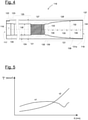
- a semicircular segment is in figure 3 shown.
- the flange insert 113 is manufactured, with the sleeves 116 being arranged in a circle at fixed distances from one another, for example by means of spacer elements.
- the laminates 114 and 115 and the sleeves 116 are hermetically sealed and infused with a matrix material, such as epoxy resin.
- the flange insert 113 is placed, for example, in a main mold for the production of a rotor blade shell and connected to further fiber layers.
- the two rotor blade segments 151 and 152 are connected via sleeves with or without flange inserts.
- the formation of the rotor blade 104 by means of the rotor blade segments 151 and 152 and the division point 150 associated therewith are optional.
- the rotor blade 104 can also not be segmented over the direction of longitudinal extension 111 .
- figure 4 12 shows a sleeve 116 according to an embodiment of the invention.
- the sleeve 116 has a first sleeve end 117 and an opposite second sleeve end 118.
- the sleeve 116 is cylindrical in shape and has a sleeve bore 119 therethrough which extends from the first sleeve end 117 to the second sleeve end 118.
- the sleeve bore 119 has a bore longitudinal axis 120, which can also be regarded as the longitudinal axis of the sleeve 116.
- the sleeve 116 has a constant outer diameter 121 and is rotationally symmetrical in shape.
- a second section 123 adjoins the first section 122, in which the wall thickness 124 of the sleeve 116 increases or the inner diameter 126 of the sleeve bore 119 decreases.
- the second section 123 is followed by a third section 125, which is again cylindrical is formed, but with a reduced inner diameter 126 compared to the first section 122.
- a threaded section 127 adjoins the third section 125, with the sleeve bore 119 having an internal thread.
- the threaded section 127 is followed by the so-called sleeve outlet 128.
- the sleeve outlet 128 relates to a section of the sleeve 116 up to the second sleeve end 118, in which the inner diameter 126 and correspondingly the wall thickness 124 of the sleeve 116 change as described below.
- the sleeve outlet 128 has an optional cylindrical section 129 which is connected to the threaded section 127 by means of an optional radius section 130 (thread undercut). Finally, the sleeve outlet 128 essentially has a widened section 131 which makes up more than 80% of the entire sleeve outlet 128—with respect to the longitudinal axis 120 of the bore. Shortly before the second sleeve end 118, the widening section 131 optionally transitions into a further cylindrical section 131a.
- the sleeve outlet 128 is formed in the widened section 131 such that an (inner) diameter 132 of the sleeve bore 119 increases in a strictly monotonous manner from a start 133 of the widened section 131 to an end 134 of the widened section 131 .
- the increase in diameter 132 is also subject to the condition that the absolute increase in diameter decreases in a strictly monotonous manner. These two conditions for the diameter 132 are met between the beginning 132 and the end 134, based on the longitudinal axis 120 of the bore.
- the widening section 131 is divided into segments 135 that are not necessarily of equal length along the longitudinal axis 120 of the bore, with the conditions being met for each segment 135, but also for two segments.
- the size and number of Segments 135 of the expansion section 131 can be freely defined.
- the segments 135 are connected to one another by radii. This results in a non-linear progression of the diameter 132.
- the profile of a wall 136 of the sleeve 116 delimiting the sleeve bore 119 also called the inner contour, is similar to an arcuate or curved profile in the expansion section 131, so that a type of champagne glass shape is formed.
- the bore 119 is further designed in such a way that the wall thickness 124 of the sleeve 116 decreases in a constant percentage along the widening section 131 in the direction of the second sleeve end 118 .
- the decrease occurs corresponding to the change in diameter 132, ie per equally long, successive path units 135.
- a wall thickness 124 of 0.6 or 0.8 mm is provided, for example. While this contributes to a stress jump in the bond, it prevents the sleeve 116 from tearing and breaking if it becomes too thin and the wall thickness 124 continues to decrease.
- a chamfer 137 of 45° is optionally formed on the second sleeve end 118 .
- figure 5 shows a superimposed shear stress profile K1 of the sleeve 116 described in the sleeve outlet 128 and a shear stress profile K2 of a sleeve in which the sleeve outlet has a conical, ie linear profile.
- the two curves are shown schematically and result under tensile load along the longitudinal axis of the bore 120 (X-axis) in an operationally assembled state in the flange insert 113. It can be seen that the course K1 is significantly flatter and more constant due to the optimized design and that there is no significant stress increase, especially at the second sleeve end 118.
- FIG 6 shows the second sleeve end 118 with the sleeve outlet 128 and an auxiliary tool 142 arranged therein, as well as a sandblasting device 144 for processing the outer surface 140 of the sleeve 116.
- the sleeve outlet 128 and in particular the further section 131a has a very small wall thickness 124. In the further section 131a, this can be, for example, only 0.8 mm or 0.6 mm or less.
- auxiliary tool 142 which is inserted from the second sleeve end 118 into the sleeve outlet 128 and rests against the wall 136 at least in the further section 131a.
- the auxiliary tool 142 has a conical shape and has a relatively high rigidity.
Landscapes
- Engineering & Computer Science (AREA)
- Life Sciences & Earth Sciences (AREA)
- Sustainable Development (AREA)
- Sustainable Energy (AREA)
- Chemical & Material Sciences (AREA)
- Combustion & Propulsion (AREA)
- Mechanical Engineering (AREA)
- General Engineering & Computer Science (AREA)
- Wind Motors (AREA)
- Turbine Rotor Nozzle Sealing (AREA)
Description
- Windenergieanlagenrotorblatt. Die Erfindung betrifft darüber hinaus einen Flanscheinleger, ein Windenergieanlagenrotorblatt sowie eine Windenergieanlage.
- Windenergieanlagen mit Rotorblättern sind aus dem Stand der Technik vielfach bekannt und werden verwendet, um Windenergie in elektrische Energie umzuwandeln. Im Bereich einer Rotorblattwurzel weisen die Rotorblätter einen Rotorblattanschluss mit einer Vielzahl von in das Laminat integrierten Hülsen auf, über welche die Rotorblätter mittels Befestigungsschrauben bzw. -schraubbolzen mit einem Lagerring eines sogenannten Pitchlagers oder mit einem mit dem Lagerring verbundenen Bauteil wie z.B. einem Extender der Windenergieanlage verbunden werden. Die Hülsen können Teil eines Flanscheinlegers für den Rotorblattanschluss sein. Ein derartiger Aufbau ist beispielsweise aus der internationalen Anmeldung
WO 2015/124568 A1 bekannt. - Die
EP 2 589 796 A1 betrifft ein Verfahren zur Herstellung eines Wurzelabschnitts eines Rotorblatts einer Windkraftanlage. Sie betrifft auch eine Stützstab-Haltevorrichtung für diesen Zweck und einen Wurzelabschnitt eines Rotorblattes einer Windkraftanlage. - Die
WO 2017/101943 A1 betrifft eine verbesserte Verbindung zum Verbinden eines Windkraftanlagen-Rotorblatts mit einer Rotornabe sowie auf ein Verfahren zur Herstellung eines Windkraftanlagen-Rotorblatts mit einer verbesserten Verbindung zum Verbinden des Windkraftanlagen-Blatts mit der Rotornabe. DieDE 10 2011 051172 A1 betrifft ein laminiertes Rotorblatt für Windenergieanlagen mit einem Befestigungssystem für Rotorblätter an der Rotornabe mittels eingearbeiteten Inserts im Rotorblattfuß oder in Rotorblattteilen. - Alternativ finden Hülsen auch bei der Verbindung von Rotorblattsegmenten Verwendung, die, der Länge nach angeordnet und zusammengefügt, ein Rotorblatt bilden. Die Hülsen befinden sich dann im Laminat eines Teilungsflansches der Rotorblattsegmente. Die Rotorblattsegmente werden über die Hülsen mittels Schraubbolzen direkt oder über geeignete Zwischenstücke miteinander verbunden.
- Eine Aufgabe, die der Erfindung zugrunde liegt, ist es, ein Konzept für Hülsen anzugeben, welches zu einem besonders verlässlichen Betrieb einer Windenergieanlage beiträgt.
- Gemäß einem ersten Aspekt wird eine Hülse für ein Windenergieanlagenrotorblatt offenbart. Die Hülse weist ein erstes Hülsenende, welches beispielsweise einem wurzelseitigen Ende des Rotorblattes zugewandt sein kann, und ein gegenüberliegendes zweites Hülsenende auf. In einem betriebsgemäß gefertigten Zustand eines Rotorblattes mit der Hülse ist das zweite Hülsenende beispielsweise einer Rotorblattspitze zugewandt. Die Hülse weist eine Hülsenbohrung auf, die sich in einem Bereich zwischen dem ersten Hülsenende und dem zweiten Hülsenende erstreckt und eine Bohrungslängsachse aufweist. Entlang der Bohrungslängsachse in Richtung des zweiten Hülsenendes weist die Hülsenbohrung einen Gewindeabschnitt auf. Weiter weist die Hülse entlang der Bohrungslängsachse in Richtung des zweiten Hülsenendes einen dem Gewindeabschnitt folgenden Hülsenauslauf auf, wobei der Hülsenauslauf einen Aufweitungsabschnitt besitzt, in welchem sich ein Durchmesser der Hülsenbohrung zumindest monoton vergrößert während eine Durchmesserzunahme zumindest monoton fällt. Es vergrößert sich der Durchmesser im Aufweitungsabschnitt derart, dass der Hülsenauslauf im Aufweitungsabschnitt einen bogenförmigen Verlauf aufweist.
- Durch einen wie oben definierten Hülsenauslauf wird zu einer gleichmäßigen Kraftübertragung zwischen der Hülse und einem damit verklebten umliegenden Faserverbundwerkstoff, etwa dem Laminat, in einem betriebsgemäß gefertigten Rotorblatt beigetragen. Dies führt zu einer erhöhten Festigkeit der Konstruktion des Rotorblattes. Weiterhin wird eine signifikante Kostensteigerung bei der Fertigung des Rotorblattes vermieden. Der Hülsenauslauf ist durch die spezielle Ausgestaltung des Aufweitungsabschnitts an eine Festigkeit der Hülse, der Verklebung und des Faserverbundwerkstoffes derart anpassbar, dass lokale Überlastungen minimiert werden.
- Es wurde erkannt, dass die Festigkeit eines Rotorblattes im Bereich des Rotorblattanschlusses bzw. des Teilungsflansches bei Rotorblattsegmenten wesentlich von drei Faktoren bestimmt ist: 1) der Festigkeit der Hülse selbst, 2) der Festigkeit einer Verklebung der Hülse mit einem umgebenden Faserverbundwerkstoff, etwa Laminat, sowie 3) der Festigkeit des die Hülse umgebenden Faserverbundwerkstoffs.
- In Bereichen, in denen sich eine Steifigkeit der miteinander verklebten Fügepartner stark ändert, können sehr hohe Schubspannungsbelastungen in der Verklebung wirken. Hier können Anrisse entstehen, die sich unter zyklischer Belastung schnell vergrößern und zu einem Versagen der Verbindung der Hülse zum Faserverbundwerkstoff führen. Eine kritische Belastung liegt vor, wenn eine am Rotorblatt angreifende Kraft die Hülse aus dem Faserverbundwerkstoff, etwa dem Laminat, herauszieht. In diesem Fall würde die Kraft von der Hülse in den Faserverbundwerkstoff über Schubspannungen in der Verklebung übertragen. Beispielsweise befinden sich Steifigkeitssprünge am Hülsenauslauf.
- Begrenzend wirkt außerdem die Festigkeit der typischerweise aus Stahl gefertigten Hülse. Die Spannungen in der Hülse können insbesondere in den dünnwandigen Bereichen die zulässige Festigkeit übersteigen. In der Folge reißt bzw. bricht die Hülse und an der Bruchstelle wird die Verklebung überlastet, weil der Steifigkeitssprung am Hülsenriss höher ist als beispielsweise an dem spitzenseitigen zweiten Hülsenende.
- Durch das erfindungsgemäße Design des Hülsenauslaufs wird eine klebegerechte Konstruktion ermöglicht. Dabei werden Spannungsverläufe und zulässige Spannungen in der Hülse selbst, in der Verklebung und in dem umgebenden Faserverbundwerkstoff des Rotorblatts berücksichtigt. Bei der erfindungsgemäßen Konstruktion ändert sich der Durchmesser im Aufweitungsabschnitt des Hülsenauslaufs zumindest abschnittsweise nicht-linear. Ein rein linearer Verlauf ist ausgeschlossen.
- Hier und im Folgenden gilt: Der Hülsenauslauf ist der zum zweiten Hülsenende führende Abschnitt der Hülse. Die Hülse ist beispielsweise zylinderförmig ausgebildet. Der Aufweitungsabschnitt ist im Querschnitt beispielsweise rotationssymmetrisch, alternative Formgebungen, etwa elliptisch oder quadratisch, sind ebenso denkbar. Zumindest monoton bedeutet, dass ein entsprechender Wert oder eine Kenngröße nicht zwingend durchgehend entlang der Bohrungslängsachse steigen bzw. abnehmen muss, sondern auch Abschnitte ohne Steigung oder Abnahme vorhanden sein können. Streng monotone Steigung bzw. Abnahme ist jedoch nicht ausgeschlossen. Die monotone Vergrößerung des Durchmessers bedeutet, dass der Durchmesser im Aufweitungsabschnitt absolut gesehen in Richtung des zweiten Hülsenendes zumindest abschnittsweise immer größer wird, jedoch keine Abschnitte umfasst, in denen der Durchmesser wieder abnimmt. Die monotone Abnahme der Durchmesserzunahme bedeutet, dass die Differenz aufeinanderfolgender Durchmesser des Hülsenauslaufs, etwa pro gleicher Wegeinheit entlang der Bohrungslängsachse, in Richtung des zweiten Hülsenendes geringer wird. Die Differenz aufeinanderfolgender Durchmesser kann abschnittsweise gleich bleiben. Die Vergrößerung des Durchmessers bzw. die Verringerung der Durchmesserzunahme gemäß obiger Bedingungen ist beispielsweise zumindest auf ein Segment des Hülsenauslaufs bezüglich der Bohrungslängsachse bezogen oder ist zumindest zwischen zwei Punkten des Aufweitungsabschnitts bezüglich der Bohrungslängsachse erfüllt.
- Mit anderen Worten ist der Durchmesser im Aufweitungsabschnitt durch eine Funktion beschreibbar, die von einem Wert x abhängt, wobei x den Abstand entlang der Längsachse ausgehend von einem Beginn des Aufweitungsabschnitt beschreibt. Diese Funktion ist entlang des gesamten Aufweitungsabschnitts monoton steigend, während die Ableitung nach x monoton abnimmt.
- Beispielsweise sind folgende Formen für den Hülsenauslauf, der beispielsweise keinen kegelförmigen und somit linearen Verlauf haben kann, denkbar: Sektglasform, Hyperbeln, Polynome, Exponentialfunktionen und Kombinationen sowie Freiformen, Splines denkbar. Ebenfalls möglich ist eine Annäherung an eine der genannten Formen mittels schrittweise gerader Linien (lineare Verlaufsabschnitte), welche direkt oder durch Übergangsradien miteinander verbunden sind.
- Bei der beschriebenen Hülse vergrößert sich der Durchmesser im Aufweitungsabschnitt derart, dass der Hülsenauslauf im Aufweitungsabschnitt einen bogenförmigen Verlauf aufweist. Dadurch weist die Hülsenbohrung im Aufweitungsabschnitt einen geschwungenen, also gekrümmten oder kurvenartigen Verlauf entlang der Bohrungslängsachse auf. Mit anderen Worten ist eine Innenkontur der Hülse des Aufweitungsabschnitts mit einem geschwungenen Verlauf gebildet. Mit wieder anderen Worten ist eine Innenkontur/Bohrungswandung im Querschnitt der Hülse des Aufweitungsabschnitts mit einem geschwungenen Verlauf gebildet. Beispielsweise ist die Bohrung im Aufweitungsabschnitt rotationsparaboloidförmig ausgebildet. Mit anderen Worten vergrößert sich der Durchmesser streng monoton, während die Durchmesserzunahme streng monoton abnimmt. Der Verlauf ist beispielsweise stetig, kann jedoch auch durch lineare Interpolation angenähert sein.
- Gemäß einer Ausführungsform weist die Hülse zumindest im Bereich des Aufweitungsabschnitts, bevorzugt im Bereich des Hülsenauslaufs, einen im Wesentlichen konstanten Außendurchmesser auf. Dies trägt zu den oben genannten Vorteilen und Funktionen bei. Im Wesentlichen schließt Ausführungsformen ein, bei denen der Außendurchmesser über die gesamte Distanz im Bereich des Aufweitungsabschnitts konstant ist. Es sind aber auch Ausführungsformen umfasst, bei denen die Hülse im Bereich des Aufweitungsabschnitts außen Erhebungen und/oder Einbuchtungen aufweist und der Außendurchmesser daher leicht variiert. Im Mittel beträgt eine Abweichung von einem konstanten Außendurchmesser nicht mehr als 5 bis 10 %.
- Gemäß einer Ausführungsform vergrößert sich der Durchmesser im Aufweitungsabschnitt derart, dass eine Wandstärke der Hülse entlang des Aufweitungsabschnitts in Richtung des zweiten Endes prozentual konstant abnimmt. Beispielsweise verjüngt sich die Wandstärke in diesem Bereich nicht-linear. Insbesondere in Kombination mit dem oben genannten konstanten Außendurchmesser ergibt sich ein besonders optimiertes Design der Hülse. Die prozentuale Abnahme ist wiederum auf die Bohrungslängsachse bezogen. Die Abnahme der Wandstärke ist analog zu oben auf zwei aufeinanderfolgende, gleich große Segmente des Aufweitungsabschnitts bzw. äquidistante Punkte entlang der Bohrungslängsachse bezogen. Die Abnahme ist prozentual gesehen konstant. Dies bedeutet im Umkehrschluss, dass die absolute Abnahme der Wandstärke in Richtung des zweiten Endes immer geringer wird. Mit anderen Worten verringert sich eine Differenz von Wandstärken entlang der Bohrungslängsachse in Richtung des zweiten Hülsenendes.
- Gemäß einer Ausführungsform vergrößert sich der Durchmesser im Aufweitungsabschnitt derart, dass eine Querschnittsfläche der Hülse entlang des Aufweitungsabschnitts in Richtung des zweiten Hülsenendes prozentual konstant abnimmt. Insbesondere in Kombination mit dem oben genannten konstanten Außendurchmesser ergibt sich ein besonders optimiertes Design der Hülse. Die prozentuale Abnahme ist wiederum auf die Bohrungslängsachse bezogen. Die Abnahme der Querschnittsfläche ist analog zu oben definiert.
- Gemäß einer Ausführungsform bildet der Aufweitungsabschnitt mindestens 50%, insbesondere mindestens 60%, mindestens 70%, mindestens 80% oder mindestens 90%, des Hülsenauslaufs. Die Prozentangaben sind wiederum auf die Bohrungslängsachse bezogen. Beispielsweise kann ein zwischen dem Gewindeabschnitt und dem Aufweitungsabschnitt ein Radiusabschnitt und/oder ein zylindrischer Abschnitt der Hülsenbohrung folgen.
- Gemäß einer Ausführungsform nimmt eine Wandstärke der Hülse zwischen dem ersten Hülsenende und dem Gewindeabschnitt, zumindest teilweise zu. Dadurch kann ein Steifigkeitssprung im Bereich des ersten Hülsenendes bei einem betriebsgemäß gefertigten Rotorblatt mit Hülse vermieden oder reduziert werden. Alternativ kann die Wandstärke in diesem Bereich auch abnehmen. Das erste Ende der Hülse ist dann aufgeweitet, um die Flächenpressung zum gegenüberliegenden Bauteil zu verringern.
- Gemäß einer Ausführungsform ist am zweiten Hülsenende eine umlaufende Fase oder ein umlaufender Radius ausgebildet. Die Fase oder der Radius dient der Fertigung eines strukturell verbesserten Hülsenendes, wodurch eine Delaminationsneigung an dieser Stelle reduziert wird.
- Gemäß einer Ausführungsform ist die Hülse einstückig gefertigt.
- Gemäß einer Ausführungsform erstreckt sich die Hülsenbohrung durchgängig von dem ersten Hülsenende zu dem zweiten Hülsenende. Eine durchgängige Hülsenbohrung erleichtert die Fertigung der Hülse. Alternativ kann die Bohrung auch an einer Stelle der Hülse unterbrochen sein. In diesem Fall gibt es zwei Bohrungen, welche sich jeweils von einem Hülsenende aus in die Hülse hinein erstrecken, auf der gleichen Bohrungslängsachse liegen und durch eine Barriere voneinander getrennt sind. Diese Barriere kann sich beispielsweise zwischen dem Gewindeabschnitt und dem Hülsenauslauf befinden. Eine derartige Ausführung ist insbesondere bei der Infusion von Vorteil, da ein Eindringen von Infusionsharz in den Gewindeabschnitt ausgeschlossen werden kann.
- Gemäß einem zweiten Aspekt wird ein Flanscheinleger für ein Windenergieanlagenrotorblatt offenbart. Der Flanscheinleger weist mehrere nebeneinander angeordnete Hülsen nach einer der obigen Ausführungen auf, wobei die Hülsen in ein oder mehrere Laminatlagen eingebettet sind. Bei Verwendung des Flanscheinlegers für den Rotorblattanschluss sind die Hülsen kreisförmig oder kreissegmentförmig nebeneinander angeordnet. Bei Verwendung des Flanscheinlegers für den Verbindungsflansch eines Rotorblattsegments können die Hülsen so nebeneinander angeordnet sein, dass sie dem Verlauf der Blattkontur folgen.
- Windenergieanlagenrotorblatt offenbart, welches einen Rotorblattanschluss mit mehreren, kreisförmig angeordneten Hülsen nach einer der obigen Ausführungen aufweist.
- Windenergieanlagenrotorblatt offenbart, welches ein Rotorblattsegment mit einem Verbindungsflansch mit mehreren, nebeneinander angeordneten Hülsen nach einer der obigen Ausführungen aufweist.
- Gemäß einem fünften Aspekt wird eine Windenergieanlage offenbart, welche einen Rotor mit einem oder mehreren Rotorblättern nach oben beschriebener Ausführung aufweist.
- Der Flanscheinleger, das Windenergieanlagenrotorblatt und die Windenergieanlage ermöglichen die vorgenannten Vorteile und Funktionen.
- Weitere Vorteile, Merkmale und Weiterbildungen ergeben sich aus den nachfolgenden, in Verbindung mit den Figuren erläuterten Ausführungsbeispielen. Gleiche, gleichartige oder gleich wirkende Elemente sind in den Figuren mit den gleichen Bezugszeichen versehen.
- In den Figuren zeigen:
-
Figur 1 eine schematische Darstellung einer Windenergieanlage gemäß einem Ausführungsbeispiel, -
Figur 2 eine schematische Darstellung eines Windenergieanlagenrotorblatts, -
Figur 3 eine schematische Darstellung eines Flanscheinlegers für das Rotorblatt, -
Figur 4 eine schematische Querschnittsansicht einer Hülse des Rotorblatts gemäß einem Ausführungsbeispiel der Erfindung, -
Figur 5 einen Schubspannungsverlauf der Hülse gemäß dem Ausführungsbeispiel im Vergleich zu einer herkömmlichen Hülse in einer schematischen Diagrammansicht und -
Figur 6 ein Werkzeug zur Fertigung der erfindungsgemäßen Hülse. -
Figur 1 zeigt eine schematische Darstellung einer Windenergieanlage 100 gemäß einem Ausführungsbeispiel. Die Windenergieanlage 100 weist einen Turm 101 auf. Der Turm 101 ist mittels eines Fundaments auf einem Untergrund befestigt. An einem dem Untergrund gegenüberliegenden Ende des Turms 101 ist eine Gondel 102 drehbar gelagert. Die Gondel 102 weist beispielsweise einen Generator auf, der über eine Rotorwelle (nicht gezeigt) mit einem Rotor 103 gekoppelt ist. Der Rotor 103 weist ein oder mehrere Rotorblätter 104 auf, die an einer Rotornabe 105 angeordnet sind. - Der Rotor 103 wird im Betrieb durch eine Luftströmung, beispielsweise Wind in Rotation versetzt. Diese Rotationsbewegung wird über die Rotorwelle und gegebenenfalls ein Getriebe auf den Generator übertragen. Der Generator wandelt die kinetische Energie des Rotors 103 in elektrische Energie um.
-
Figur 2 zeigt ein exemplarisches Rotorblatt 104 der Windenergieanlage 100. Das Rotorblatt 104 hat die Form eines herkömmlichen Rotorblattes und hat einen Rotorblattwurzelbereich 106, der der Rotornabe 105 zugewandt und zugeordnet ist. Der Rotorblattwurzelbereich 106 hat typischerweise einen im Wesentlichen kreisrunden Querschnitt. An den Rotorblattwurzelbereich 106 schließen sich ein Übergangsbereich 107 und ein Profilbereich 108 des Rotorblatts 104 an. Das Rotorblatt 104 hat bezüglich einer Längserstreckungsrichtung 111 eine Druckseite 109 und eine gegenüberliegende Saugseite 110. Das Rotorblatt 104 ist im Inneren im Wesentlichen hohl ausgebildet. - Im Rotorblattwurzelbereich 106 ist ein Rotorblattanschluss 112 vorgesehen, mittels welchem das Rotorblatt 104 mit der Rotornabe 105 mechanisch verbunden wird.
- Das Rotorblatt 104 weist eine Teilungsstelle 150 auf, an welcher ein blattwurzelseitiges Rotorblattsegment 151 und ein blattspitzenseitiges Rotorblattsegment 152 über Teilungsflansche miteinander verbunden sind.
- Zur Herstellung des Rotorblattanschlusses 112 ist typischerweise ein Flanscheinleger 113 vorgesehen. Dabei handelt es sich um ein kreisbogeninnen und -außenseitiges Laminat 114 und 115, in welches in Längserstreckungsrichtung 111 Hülsen 116 mit Gewinden eingebettet sind. Bei den Hülsen 116 handelt es sich beispielsweise um metallische Hülsen, insbesondere Stahlhülsen. Ein halbkreisförmiges Segment ist in
Figur 3 gezeigt. Zunächst wird der Flanscheinleger 113 gefertigt, wobei die Hülsen 116 in festen Abständen zueinander, etwa mittels Abstandselementen, kreisförmig angeordnet werden. Anschließend werden die Laminate 114 und 115 sowie die Hülsen 116 luftdicht verschlossen und mit einem Matrixwerkstoff, etwa Epoxidharz infundiert. In einem weiteren Schritt wird der Flanscheinleger 113 beispielsweise in eine Hauptform zur Fertigung einer Rotorblattschale eingelegt und mit weiteren Faserlagen verbunden. - Es ist jedoch auch denkbar, dass kein Flanscheinleger 113 vorgesehen ist und die Hülsen 116 direkt in das Laminat des Rotorblatts 104, etwa in Rotorblatthalbschalen, eingebettet werden.
- Analog sind die beiden Rotorblattsegmente 151 und 152 über Hülsen mit oder ohne Flanscheinleger verbunden.
- Es sei an dieser Stelle erwähnt, dass die Ausbildung des Rotorblattes 104 mittels der Rotorblattsegmente 151 und 152 und die damit verbundene Teilungsstelle 150 optional sind. Das Rotorblatt 104 kann über die Längserstreckungsrichtung 111 auch nicht segmentiert sein.
-
Figur 4 zeigt eine Hülse 116 gemäß einem Ausführungsbeispiel der Erfindung. - Die Hülse 116 gemäß
Figur 4 hat ein erstes Hülsenende 117 und ein gegenüberliegendes zweites Hülsenende 118. Die Hülse 116 ist zylindrisch geformt und hat eine durchgängige Hülsenbohrung 119, die sich vom ersten Hülsenende 117 zum zweiten Hülsenende 118 erstreckt. Die Hülsenbohrung 119 hat eine Bohrungslängsachse 120, die auch als Längsachse der Hülse 116 angesehen werden kann. Die Hülse 116 hat einen konstanten Außendurchmesser 121 und ist rotationssymmetrisch geformt. - Ausgehend von dem ersten Hülsenende 117 hat die Hülsenbohrung 119 - hier und im Folgenden stets auf die Bohrungslängsachse 120 bezogen - einen ersten Abschnitt 122, der zylindrisch ausgebildet ist. An den ersten Abschnitt 122 schließt ein zweiter Abschnitt 123 an, bei dem sich die Wandstärke 124 der Hülse 116 vergrößert bzw. der Innendurchmesser 126 der Hülsenbohrung 119 verringert. An den zweiten Abschnitt 123 schließt ein dritter Abschnitt 125 an, der wieder zylindrisch ausgebildet ist, jedoch mit im Vergleich zum ersten Abschnitt 122 verringertem Innendurchmesser 126. An den dritten Abschnitt 125 schließt ein Gewindeabschnitt 127 an, wobei die Hülsenbohrung 119 ein Innengewinde aufweist. Dem Gewindeabschnitt 127 folgt der sogenannte Hülsenauslauf 128. Der Hülsenauslauf 128 betrifft einen Abschnitt der Hülse 116 bis zum zweiten Hülsenende 118, in welchem sich der Innendurchmesser 126 und korrespondierend die Wandstärke 124 der Hülse 116 wie nachfolgend beschrieben verändern.
- Der Hülsenauslauf 128 weist einen optionalen zylindrischen Abschnitt 129 auf, der mittels eines optionalen Radiusabschnitts 130 mit dem Gewindeabschnitt 127 verbunden ist (Gewindefreistich). Schließlich weist der Hülsenauslauf 128 wesentlich einen Aufweitungsabschnitt 131 auf, der mehr als 80 % des gesamten Hülsenauslaufs 128 - bezüglich der Bohrungslängsachse 120 - ausmacht. Kurz vor dem zweiten Hülsenende 118 geht der Aufweitungsabschnitt 131 optional in einen weiteren zylindrischen Abschnitt 131a über.
- Der Hülsenauslauf 128 ist im Aufweitungsabschnitt 131 so ausgebildet, dass sich ein (Innen-)Durchmesser 132 der Hülsenbohrung 119 von einem Beginn 133 des Aufweitungsabschnitts 131 bis zu einem Ende 134 des Aufweitungsabschnitts 131 streng monoton vergrößert. Die Vergrößerung des Durchmessers 132 unterliegt zudem noch der Bedingung, dass die absolute Durchmesserzunahme streng monoton abnimmt. Diese beiden Bedingungen für den Durchmesser 132 sind zwischen dem Beginn 132 und dem Ende 134, bezogen auf die Bohrungslängsachse 120, erfüllt. Im Ausführungsbeispiel ist der Aufweitungsabschnitt 131 in nicht zwingend gleichlange Segmente 135 entlang der Bohrungslängsachse 120 unterteilt, wobei die Bedingungen für jedes Segment 135, aber auch über zwei Segmente hinweg erfüllt sind. Die Größe und Anzahl der Segmente 135 des Aufweitungsabschnitts 131 sind frei definierbar. Die Segmente 135 sind durch Radien miteinander verbunden. Dadurch ergibt sich ein nicht-linearer Verlauf des Durchmessers 132. Im gezeigten Querschnitt gemäß
Figur 4 gleicht der Verlauf einer die Hülsenbohrung 119 begrenzenden Wandung 136 der Hülse 116, auch Innenkontur genannt, dadurch im Aufweitungsabschnitt 131 einem bogenförmigen oder gekrümmten Verlauf, so dass eine Art Sektglasform gebildet ist. - Die Bohrung 119 ist weiter so gestaltet, dass die Wandstärke 124 der Hülse 116 entlang des Aufweitungsabschnitts 131 in Richtung des zweiten Hülsenendes 118 prozentual konstant abnimmt. Die Abnahme erfolgt korrespondierend zu der Veränderung des Durchmessers 132, also pro gleich langer, aufeinanderfolgender Wegeinheiten 135. Am zweiten Hülsenende 118, etwa im weiteren zylindrischen Abschnitt 131a, ist beispielsweise eine Wandstärke 124 von 0,6 oder 0,8 mm vorgesehen. Dies trägt zwar zu einem Spannungssprung in der Verklebung bei, verhindert auf der anderen Seite jedoch ein Reißen und Brechen der Hülse 116, wenn diese zu dünn wird und die Wandstärke 124 weiter abnimmt.
- Durch die beschriebene Hülsenauslaufform werden die eingangs genannten Vorteile und Funktionen ermöglicht.
- Optional ist am zweiten Hülsenende 118 eine Fase 137 von 45° ausgebildet.
-
Figur 5 zeigt überlagert einen Schubspannungsverlauf K1 der beschriebenen Hülse 116 im Hülsenauslauf 128 und einen Schubspannungsverlauf K2 einer Hülse, bei der der Hülsenauslauf einen kegeligen, also linearen Verlauf hat. Die beiden Verläufe sind schematisch gezeigt und ergeben sich unter Zugbelastung entlang der Bohrungslängsachse 120 (X-Achse) in einem betriebsgemäß montierten Zustand im Flanscheinleger 113. Man erkennt, dass der Verlauf K1 durch das optimierte Design deutlich flacher und konstanter ist und insbesondere am zweiten Hülsenende 118 keine signifikante Spannungsüberhöhung stattfindet. -
Figur 6 zeigt das zweite Hülsenende 118 mit dem Hülsenauslauf 128 und einem darin angeordneten Hilfswerkzeug 142, sowie eine Sandstrahl-Vorrichtung 144 zur Bearbeitung der äußeren Oberfläche 140 der Hülse 116. Der Hülsenauslauf 128 und insbesondere der weitere Abschnitt 131a weist eine sehr geringe Wandstärke 124 auf. Diese kann im weiteren Abschnitt 131a beispielsweise nur noch 0,8 mm oder 0,6 mm oder weniger betragen. Bei einer Oberflächenbearbeitung der Hülse 116 durch Sandstrahlen, initiales Drehen oder Sheradisieren besteht die Gefahr, dass sich der Hülsenauslauf 128 im weiteren Abschnitt 131a nach innen verbiegt. Abhilfe schafft hier ein Hilfswerkzeug 142, welches vom zweiten Hülsenende 118 aus in den Hülsenauslauf 128 eingesetzt wird und zumindest im weiteren Abschnitt 131a an der Wandung 136 anliegt. Das Hilfswerkzeug 142 weist eine keglige Form auf und besitzt eine relativ hohe Steifigkeit. -
- 100
- Windenergieanlage
- 101
- Turm
- 102
- Gondel
- 103
- Rotor
- 104
- (Windenergieanlagen)Rotorblatt
- 105
- Rotornabe
- 106
- Rotorblattwurzelbereich
- 107
- Übergangsbereich
- 108
- Profilbereich
- 109
- Druckseite
- 110
- Saugseite
- 111
- Längserstreckungsrichtung
- 112
- Rotorblattanschluss
- 113
- Flanscheinleger
- 114
- Laminat
- 115
- Laminat
- 116
- Hülse
- 117
- erstes Hülsenende
- 118
- zweites Hülsenende
- 119
- Hülsenbohrung
- 120
- Bohrungslängsachse
- 121
- Außendurchmesser
- 122
- erster Abschnitt
- 123
- zweiter Abschnitt
- 124
- Wandstärke
- 125
- dritter Abschnitt
- 126
- Innendurchmesser
- 127
- Gewindeabschnitt
- 128
- Hülsenauslauf
- 129
- zylindrischer Abschnitt
- 130
- Radiusabschnitt
- 131
- Aufweitungsabschnitt
- 131a
- weiterer Abschnitt
- 132
- Durchmesser
- 133
- Beginn
- 134
- Ende
- 135
- Segment
- 136
- Wandung
- 137
- Fase
- 140
- Oberfläche
- 142
- Hilfswerkzeug
- 144
- Sandstrahl-Vorrichtung
- 150
- Teilungsstelle
- 151
- blattwurzelseitiges Rotorblattsegment
- 152
- blattspitzenseitiges Rotorblattsegment
- K1
- Schubspannungsverlauf entsprechend einer Hülse gemäß dem Ausführungsbeispiel der Erfindung
- K2
- Schubspannungsverlauf entsprechend einer Hülse aus dem Stand der Technik
Claims (13)
- Hülse (116) für ein Windenergieanlagenrotorblatt (104), die Hülse (116) aufweisend- ein erstes Hülsenende (117 und ein gegenüberliegendes zweites Hülsenende (118); und- eine Hülsenbohrung (119), die sich in einem Bereich zwischen dem ersten Hülsenende (117) und dem zweiten Hülsenende (118) erstreckt und eine Bohrungslängsachse (120) aufweist;wobei, entlang der Bohrungslängsachse (120) in Richtung des zweiten Hülsenendes (118),- die Hülsenbohrung (119) einen Gewindeabschnitt (127) aufweist, und- die Hülse (116) einen dem Gewindeabschnitt (127) folgenden Hülsenauslauf (128) aufweist, der einen Aufweitungsabschnitt (131) der Hülsenbohrung (119) umfasst, in welchem sich ein Durchmesser (132) der Hülsenbohrung (119) monoton vergrößert während eine Durchmesserzunahme monoton abnimmt, wobei sich der Durchmesser (132) im Aufweitungsabschnitt (131) derart vergrößert, dass der Hülsenauslauf (128) im Aufweitungsabschnitt (131) einen bogenförmigen Verlauf aufweist.
- Hülse (116) nach Anspruch 1, wobei die Hülse (116) zumindest im Bereich des Aufweitungsabschnitts (131), bevorzugt im Bereich des Hülsenauslaufs (128), einen konstanten Außendurchmesser (121) aufweist.
- Hülse (116) nach einem der vorhergehenden Ansprüche, wobei sich der Durchmesser (132) im Aufweitungsabschnitt (131) derart vergrößert, dass eine Wandstärke (124) der Hülse (116) entlang des Aufweitungsabschnitts (131) in Richtung des zweiten Hülsenendes (118) prozentual konstant abnimmt.
- Hülse (116) nach einem der Ansprüche 1 bis 2, wobei sich der Durchmesser (132) im Aufweitungsabschnitt (131) derart vergrößert, dass eine Querschnittsfläche der Hülse (116) entlang des Aufweitungsabschnitts (131) in Richtung des zweiten Hülsenendes (118) prozentual konstant abnimmt.
- Hülse (116) nach einem der vorhergehenden Ansprüche, wobei der Aufweitungsabschnitt (131) mindestens 50%, insbesondere mindestens 60%, mindestens 70%, mindestens 80% oder mindestens 90%, des Hülsenauslaufs (128) bildet.
- Hülse (116) nach einem der vorhergehenden Ansprüche, wobei eine Wandstärke (124) der Hülse (116) zwischen dem ersten Hülsenende (117) und dem Gewindeabschnitt (127), zumindest teilweise zunimmt.
- Hülse (116) nach einem der vorhergehenden Ansprüche, wobei am zweiten Hülsenende (118) eine umlaufende Fase (137) oder ein umlaufender Radius ausgebildet ist.
- Hülse (116) nach einem der vorhergehenden Ansprüche, wobei die Hülse (116) einstückig gefertigt ist.
- Hülse (116) nach einem der vorhergehenden Ansprüche, wobei sich die Hülsenbohrung (119) durchgängig von dem ersten Hülsenende (117) zu dem zweiten Hülsenende (118) erstreckt.
- Flanscheinleger für ein Windenergieanlagenrotorblatt (104), aufweisend mehrere nebeneinander angeordnete Hülsen (116) nach einem der vorhergehenden Ansprüche, wobei die Hülsen (116) in ein oder mehrere Laminatlagen eingebettet sind.
- Windenergieanlagenrotorblatt (104), aufweisend einen Rotorblattanschluss (112) mit mehreren, kreisförmig angeordneten Hülsen (116) nach einem der vorhergehenden Ansprüche.
- Windenergieanlagenrotorblatt (104), aufweisend ein Rotorblattsegment mit einem Verbindungsflansch mit mehreren, nebeneinander angeordneten Hülsen (116) nach einem der vorhergehenden Ansprüche.
- Windenergieanlage (100), aufweisend
einen Rotor (103) mit einem oder mehreren Rotorblättern (104) nach einem der vorhergehenden Ansprüche.
Priority Applications (6)
| Application Number | Priority Date | Filing Date | Title |
|---|---|---|---|
| ES18167560T ES2918026T3 (es) | 2018-04-16 | 2018-04-16 | Cojinete para una pala de rotor de turbina eólica, inserto de pestaña, pala de rotor de turbina eólica y turbina eólica |
| DK18167560.4T DK3557041T3 (da) | 2018-04-16 | 2018-04-16 | Hylse til et vindenergianlægsrotorblad, flangeindlæg, vindener-gianlægsrotorblad og vindenergianlæg |
| EP18167560.4A EP3557041B1 (de) | 2018-04-16 | 2018-04-16 | Hülse für ein windenergieanlagenrotorblatt, flanscheinleger, windenergieanlagenrotorblatt und windenergieanlage |
| US16/372,157 US10883472B2 (en) | 2018-04-16 | 2019-04-01 | Bushing for a wind turbine rotor blade, flange insert, wind turbine rotor blade and wind turbine |
| MX2019004369A MX2019004369A (es) | 2018-04-16 | 2019-04-12 | Cojinete para una pala de rotor de turbina eolica, inserto de pestaña, pala de rotor de turbina eolica y turbina eolica. |
| CN201910293704.5A CN110388298A (zh) | 2018-04-16 | 2019-04-12 | 风力涡轮机、风力涡轮机转子叶片及其衬套、凸缘插入件 |
Applications Claiming Priority (1)
| Application Number | Priority Date | Filing Date | Title |
|---|---|---|---|
| EP18167560.4A EP3557041B1 (de) | 2018-04-16 | 2018-04-16 | Hülse für ein windenergieanlagenrotorblatt, flanscheinleger, windenergieanlagenrotorblatt und windenergieanlage |
Publications (2)
| Publication Number | Publication Date |
|---|---|
| EP3557041A1 EP3557041A1 (de) | 2019-10-23 |
| EP3557041B1 true EP3557041B1 (de) | 2022-03-16 |
Family
ID=62002565
Family Applications (1)
| Application Number | Title | Priority Date | Filing Date |
|---|---|---|---|
| EP18167560.4A Active EP3557041B1 (de) | 2018-04-16 | 2018-04-16 | Hülse für ein windenergieanlagenrotorblatt, flanscheinleger, windenergieanlagenrotorblatt und windenergieanlage |
Country Status (6)
| Country | Link |
|---|---|
| US (1) | US10883472B2 (de) |
| EP (1) | EP3557041B1 (de) |
| CN (1) | CN110388298A (de) |
| DK (1) | DK3557041T3 (de) |
| ES (1) | ES2918026T3 (de) |
| MX (1) | MX2019004369A (de) |
Families Citing this family (4)
| Publication number | Priority date | Publication date | Assignee | Title |
|---|---|---|---|---|
| CN114729621B (zh) * | 2021-10-05 | 2025-08-29 | 远景能源技术私人有限公司 | 一种根部衬套、其衬套插入件、包括该根部衬套的风力发电机叶片及其制造方法 |
| CN118715364A (zh) * | 2021-12-21 | 2024-09-27 | 维斯塔斯风力系统有限公司 | 用于将风力涡轮机中的转子叶片连接到转子轮毂的衬套 |
| WO2023169677A1 (en) * | 2022-03-10 | 2023-09-14 | Nordex Energy Se & Co. Kg | Wind turbine rotor blade and method of joining two rotor blade segments |
| CN115111248A (zh) * | 2022-08-02 | 2022-09-27 | 远景能源有限公司 | 一种预埋螺栓套及风力发电机 |
Family Cites Families (23)
| Publication number | Priority date | Publication date | Assignee | Title |
|---|---|---|---|---|
| US2984453A (en) * | 1957-03-25 | 1961-05-16 | Westinghouse Electric Corp | Vibration damper for blading in elastic fluid apparatus |
| US4360288A (en) * | 1979-09-17 | 1982-11-23 | Fiberflex Products, Inc. | Fiberglass sucker rod construction |
| US4915590A (en) * | 1987-08-24 | 1990-04-10 | Fayette Manufacturing Corporation | Wind turbine blade attachment methods |
| CA2126048A1 (en) * | 1993-06-18 | 1994-12-19 | Paul Costain | Quick coupling cue stick |
| DE60312816T2 (de) * | 2002-01-11 | 2008-02-07 | Fiberline A/S | Verfahren zur herstellung eines faserverstärkten lasttragenden elements |
| WO2006070171A1 (en) * | 2004-12-29 | 2006-07-06 | Vestas Wind Systems A/S | Method of manufacturing a wind turbine blade shell member with a fastening member and a wind turbine blade with a fastening member |
| DE102008021498A1 (de) * | 2008-04-29 | 2009-11-05 | Repower Systems Ag | Verfahren zur Fertigung eines Blattanschlusses eines Rotorblatts, ein Blattanschluss und ein Befestigungselement für einen Blattanschluss |
| MX2011008024A (es) * | 2009-02-16 | 2011-08-17 | Vestas Wind Sys As | Una helice para una turbina eolica y un metodo para hacer la misma. |
| US8025485B2 (en) * | 2010-06-17 | 2011-09-27 | General Electric Company | Wind turbine blade attachment configuration with flattened bolts |
| DE102011051172A1 (de) * | 2011-06-17 | 2012-12-20 | Lars Kästner | Laminiertes Rotorblatt für Windenergieanlagen mit einem Befestigungssystem für Rotorblätter an der Rotornabe |
| DK2551512T3 (da) * | 2011-07-27 | 2014-07-21 | Alstom Renovables Espana Sl | Forbindelsesanordning på en vindmøllevinge |
| EP2554834B1 (de) * | 2011-08-02 | 2016-07-13 | Alstom Wind, S.L.U. | Rotor für eine Windturbine |
| EP2589796B1 (de) * | 2011-11-04 | 2015-07-29 | Siemens Aktiengesellschaft | Herstellung eines Wurzelabschnitts |
| EP2781344B1 (de) * | 2013-03-21 | 2019-10-09 | GE Renewable Technologies Wind B.V. | Verfahren zur Herstellung eines Teils eines Windturbinenblatts |
| GB201402830D0 (en) | 2014-02-18 | 2014-04-02 | Lm Wp Patent Holding As | Wind turbine blade brushing system |
| NL2012326C2 (nl) | 2014-02-25 | 2015-08-26 | Viventus Holding B V | Bus bestemd voor het direct of indirect verbinden van een bladwortel van een windturbineblad aan een naaf van een turbine. |
| DE102014008558B4 (de) * | 2014-05-28 | 2019-09-12 | Windnovation Engineering Solutions Gmbh | Rotorblattanschluss |
| EP2952734B1 (de) * | 2014-06-05 | 2021-04-07 | Siemens Gamesa Renewable Energy A/S | Wurzelbuchse für eine rotorblattwurzel eines windturbinenrotorblatts, rotorblattwurzel, windturbinenrotorblatt und windturbine |
| EP2952739A1 (de) | 2014-06-05 | 2015-12-09 | Siemens Aktiengesellschaft | Wurzelbuchse für einen Schaufelfuß einer Windturbinenrotorschaufel, Windturbinenrotorschaufel und Windturbine |
| EP2963282B1 (de) * | 2014-07-04 | 2018-10-24 | Siemens Aktiengesellschaft | Montierringanordnug für das Blatt einer Windturbine |
| EP3034862B1 (de) * | 2014-12-15 | 2019-05-08 | GE Renewable Technologies Wind B.V. | Verschraubte Befestigung zum Befestigen von Windturbinenteilen |
| US10190571B2 (en) * | 2015-07-01 | 2019-01-29 | General Electric Company | Ring insert for a wind turbine rotor blade |
| US10975838B2 (en) * | 2015-12-14 | 2021-04-13 | Vestas Wind Systems A/S | Joint for connecting a wind turbine rotor blade to a rotor hub and associated method |
-
2018
- 2018-04-16 EP EP18167560.4A patent/EP3557041B1/de active Active
- 2018-04-16 DK DK18167560.4T patent/DK3557041T3/da active
- 2018-04-16 ES ES18167560T patent/ES2918026T3/es active Active
-
2019
- 2019-04-01 US US16/372,157 patent/US10883472B2/en active Active
- 2019-04-12 CN CN201910293704.5A patent/CN110388298A/zh active Pending
- 2019-04-12 MX MX2019004369A patent/MX2019004369A/es unknown
Also Published As
| Publication number | Publication date |
|---|---|
| US20190316564A1 (en) | 2019-10-17 |
| US10883472B2 (en) | 2021-01-05 |
| EP3557041A1 (de) | 2019-10-23 |
| MX2019004369A (es) | 2020-02-07 |
| DK3557041T3 (da) | 2022-06-07 |
| CN110388298A (zh) | 2019-10-29 |
| ES2918026T3 (es) | 2022-07-13 |
Similar Documents
| Publication | Publication Date | Title |
|---|---|---|
| EP3557041B1 (de) | Hülse für ein windenergieanlagenrotorblatt, flanscheinleger, windenergieanlagenrotorblatt und windenergieanlage | |
| EP4038271B1 (de) | Windenergieanlagenrotorblatt und verfahren zum verbinden zweier rotorblattsegmente | |
| EP3855014B1 (de) | Geteiltes rotorblatt einer windenergieanlage sowie rotorblattsegment | |
| EP2283231B2 (de) | Verfahren zur fertigung eines blattanschlusses eines rotorblatts, ein blattanschluss und ein befestigungselement für einen blattanschluss | |
| EP3469212B1 (de) | Rotor für eine windenergieanlage, rotorblatt für eine windenergieanlage, hülse und verfahren zur montage eines rotors | |
| EP1024081B1 (de) | Blattwurzel für Propeller- und Rotorblätter | |
| EP1780445B1 (de) | Zahnrad | |
| EP2035694B1 (de) | Rotornabe einer windenergieanlage | |
| EP2434144B1 (de) | Rotorblatt oder Rotorblattsegment für eine Windenergieanlage | |
| EP2882962B1 (de) | Rotorwelle für eine windturbine | |
| EP3018342B1 (de) | Verfahren zum herstellen eines rotorblatts einer windenergieanlage | |
| EP3665384B1 (de) | Rotorblatt eines rotors einer windenergieanlage, windenergieanlage und verfahren zur verbesserung des wirkungsgrades eines rotors einer windenergieanlage | |
| EP3929431B1 (de) | Bausatz und verfahren zum verbinden zweier rotorblattsegmente eines windenergieanlagenrotorblatts | |
| EP2592264B1 (de) | Blattanschluss für ein Rotorblatt einer Windenergieanlage | |
| EP3559417B1 (de) | Verfahren zum herstellen eines windenergieanlagen-rotorblattes und windenergieanlagen-rotorblatt | |
| EP3657012B1 (de) | Zentrierbolzen für die herstellung einer flanschverbindung zwischen zwei bauteilen einer windenergieanlage, verfahren zum herstellen einer flanschverbindung sowie flanschverbindung | |
| DE102017106875B4 (de) | Windkraftanlage und Verfahren zu dessen Montage | |
| EP4155530A1 (de) | Windenergieanlagen-rotorblatt und verfahren zur montage eines windenergieanlagen- rotorblattes | |
| EP3561292B1 (de) | Befestigungsschraubbolzen für die herstellung eines flanschanschlusses eines windenergieanlagenrotorblatts, system, verfahren, flanscheinleger, rotorblatt sowie windenergieanlage | |
| EP4018089B1 (de) | Rotorblattanschluss mit insert und dehnhülse | |
| EP3844384B1 (de) | Rotor mit rotorblatt, windenergieanlage und verfahren zum optimieren einer windenergieanlage | |
| EP3564523B1 (de) | Flanschanschluss für ein windenergieanlagenrotorblatt, versteifungslage für einen flanschanschluss, flanscheinleger, windenergieanlagenrotorblatt, windenergieanlage sowie verfahren zum herstellen eines flanschanschlusses | |
| EP2896788B1 (de) | Strangrprofil zur herstellung einer leitschaufel und herstellungsverfahren | |
| EP4400712A1 (de) | Insert für ein windenergieanlagenrotorblatt sowie windenergieanlagenrotorblatt | |
| EP3653872A1 (de) | Verfahren zum herstellen zweier rotorblattsegmente, rotorblattsegment sowie geteiltes rotorblatt |
Legal Events
| Date | Code | Title | Description |
|---|---|---|---|
| PUAI | Public reference made under article 153(3) epc to a published international application that has entered the european phase |
Free format text: ORIGINAL CODE: 0009012 |
|
| STAA | Information on the status of an ep patent application or granted ep patent |
Free format text: STATUS: THE APPLICATION HAS BEEN PUBLISHED |
|
| AK | Designated contracting states |
Kind code of ref document: A1 Designated state(s): AL AT BE BG CH CY CZ DE DK EE ES FI FR GB GR HR HU IE IS IT LI LT LU LV MC MK MT NL NO PL PT RO RS SE SI SK SM TR |
|
| AX | Request for extension of the european patent |
Extension state: BA ME |
|
| STAA | Information on the status of an ep patent application or granted ep patent |
Free format text: STATUS: REQUEST FOR EXAMINATION WAS MADE |
|
| 17P | Request for examination filed |
Effective date: 20200326 |
|
| RBV | Designated contracting states (corrected) |
Designated state(s): AL AT BE BG CH CY CZ DE DK EE ES FI FR GB GR HR HU IE IS IT LI LT LU LV MC MK MT NL NO PL PT RO RS SE SI SK SM TR |
|
| RAP3 | Party data changed (applicant data changed or rights of an application transferred) |
Owner name: NORDEX ENERGY SE & CO. KG |
|
| GRAP | Despatch of communication of intention to grant a patent |
Free format text: ORIGINAL CODE: EPIDOSNIGR1 |
|
| STAA | Information on the status of an ep patent application or granted ep patent |
Free format text: STATUS: GRANT OF PATENT IS INTENDED |
|
| INTG | Intention to grant announced |
Effective date: 20211020 |
|
| GRAS | Grant fee paid |
Free format text: ORIGINAL CODE: EPIDOSNIGR3 |
|
| GRAA | (expected) grant |
Free format text: ORIGINAL CODE: 0009210 |
|
| STAA | Information on the status of an ep patent application or granted ep patent |
Free format text: STATUS: THE PATENT HAS BEEN GRANTED |
|
| AK | Designated contracting states |
Kind code of ref document: B1 Designated state(s): AL AT BE BG CH CY CZ DE DK EE ES FI FR GB GR HR HU IE IS IT LI LT LU LV MC MK MT NL NO PL PT RO RS SE SI SK SM TR |
|
| REG | Reference to a national code |
Ref country code: GB Ref legal event code: FG4D Free format text: NOT ENGLISH |
|
| REG | Reference to a national code |
Ref country code: CH Ref legal event code: EP Ref country code: DE Ref legal event code: R096 Ref document number: 502018009077 Country of ref document: DE |
|
| REG | Reference to a national code |
Ref country code: IE Ref legal event code: FG4D Free format text: LANGUAGE OF EP DOCUMENT: GERMAN |
|
| REG | Reference to a national code |
Ref country code: AT Ref legal event code: REF Ref document number: 1476043 Country of ref document: AT Kind code of ref document: T Effective date: 20220415 |
|
| REG | Reference to a national code |
Ref country code: DK Ref legal event code: T3 Effective date: 20220602 |
|
| REG | Reference to a national code |
Ref country code: LT Ref legal event code: MG9D |
|
| REG | Reference to a national code |
Ref country code: ES Ref legal event code: FG2A Ref document number: 2918026 Country of ref document: ES Kind code of ref document: T3 Effective date: 20220713 |
|
| REG | Reference to a national code |
Ref country code: NL Ref legal event code: MP Effective date: 20220316 |
|
| PG25 | Lapsed in a contracting state [announced via postgrant information from national office to epo] |
Ref country code: SE Free format text: LAPSE BECAUSE OF FAILURE TO SUBMIT A TRANSLATION OF THE DESCRIPTION OR TO PAY THE FEE WITHIN THE PRESCRIBED TIME-LIMIT Effective date: 20220316 Ref country code: RS Free format text: LAPSE BECAUSE OF FAILURE TO SUBMIT A TRANSLATION OF THE DESCRIPTION OR TO PAY THE FEE WITHIN THE PRESCRIBED TIME-LIMIT Effective date: 20220316 Ref country code: NO Free format text: LAPSE BECAUSE OF FAILURE TO SUBMIT A TRANSLATION OF THE DESCRIPTION OR TO PAY THE FEE WITHIN THE PRESCRIBED TIME-LIMIT Effective date: 20220616 Ref country code: LT Free format text: LAPSE BECAUSE OF FAILURE TO SUBMIT A TRANSLATION OF THE DESCRIPTION OR TO PAY THE FEE WITHIN THE PRESCRIBED TIME-LIMIT Effective date: 20220316 Ref country code: HR Free format text: LAPSE BECAUSE OF FAILURE TO SUBMIT A TRANSLATION OF THE DESCRIPTION OR TO PAY THE FEE WITHIN THE PRESCRIBED TIME-LIMIT Effective date: 20220316 Ref country code: BG Free format text: LAPSE BECAUSE OF FAILURE TO SUBMIT A TRANSLATION OF THE DESCRIPTION OR TO PAY THE FEE WITHIN THE PRESCRIBED TIME-LIMIT Effective date: 20220616 |
|
| PG25 | Lapsed in a contracting state [announced via postgrant information from national office to epo] |
Ref country code: LV Free format text: LAPSE BECAUSE OF FAILURE TO SUBMIT A TRANSLATION OF THE DESCRIPTION OR TO PAY THE FEE WITHIN THE PRESCRIBED TIME-LIMIT Effective date: 20220316 Ref country code: GR Free format text: LAPSE BECAUSE OF FAILURE TO SUBMIT A TRANSLATION OF THE DESCRIPTION OR TO PAY THE FEE WITHIN THE PRESCRIBED TIME-LIMIT Effective date: 20220617 Ref country code: FI Free format text: LAPSE BECAUSE OF FAILURE TO SUBMIT A TRANSLATION OF THE DESCRIPTION OR TO PAY THE FEE WITHIN THE PRESCRIBED TIME-LIMIT Effective date: 20220316 |
|
| PG25 | Lapsed in a contracting state [announced via postgrant information from national office to epo] |
Ref country code: NL Free format text: LAPSE BECAUSE OF FAILURE TO SUBMIT A TRANSLATION OF THE DESCRIPTION OR TO PAY THE FEE WITHIN THE PRESCRIBED TIME-LIMIT Effective date: 20220316 |
|
| PG25 | Lapsed in a contracting state [announced via postgrant information from national office to epo] |
Ref country code: SM Free format text: LAPSE BECAUSE OF FAILURE TO SUBMIT A TRANSLATION OF THE DESCRIPTION OR TO PAY THE FEE WITHIN THE PRESCRIBED TIME-LIMIT Effective date: 20220316 Ref country code: SK Free format text: LAPSE BECAUSE OF FAILURE TO SUBMIT A TRANSLATION OF THE DESCRIPTION OR TO PAY THE FEE WITHIN THE PRESCRIBED TIME-LIMIT Effective date: 20220316 Ref country code: RO Free format text: LAPSE BECAUSE OF FAILURE TO SUBMIT A TRANSLATION OF THE DESCRIPTION OR TO PAY THE FEE WITHIN THE PRESCRIBED TIME-LIMIT Effective date: 20220316 Ref country code: PT Free format text: LAPSE BECAUSE OF FAILURE TO SUBMIT A TRANSLATION OF THE DESCRIPTION OR TO PAY THE FEE WITHIN THE PRESCRIBED TIME-LIMIT Effective date: 20220718 Ref country code: EE Free format text: LAPSE BECAUSE OF FAILURE TO SUBMIT A TRANSLATION OF THE DESCRIPTION OR TO PAY THE FEE WITHIN THE PRESCRIBED TIME-LIMIT Effective date: 20220316 Ref country code: CZ Free format text: LAPSE BECAUSE OF FAILURE TO SUBMIT A TRANSLATION OF THE DESCRIPTION OR TO PAY THE FEE WITHIN THE PRESCRIBED TIME-LIMIT Effective date: 20220316 |
|
| PG25 | Lapsed in a contracting state [announced via postgrant information from national office to epo] |
Ref country code: PL Free format text: LAPSE BECAUSE OF FAILURE TO SUBMIT A TRANSLATION OF THE DESCRIPTION OR TO PAY THE FEE WITHIN THE PRESCRIBED TIME-LIMIT Effective date: 20220316 Ref country code: IS Free format text: LAPSE BECAUSE OF FAILURE TO SUBMIT A TRANSLATION OF THE DESCRIPTION OR TO PAY THE FEE WITHIN THE PRESCRIBED TIME-LIMIT Effective date: 20220716 Ref country code: AL Free format text: LAPSE BECAUSE OF FAILURE TO SUBMIT A TRANSLATION OF THE DESCRIPTION OR TO PAY THE FEE WITHIN THE PRESCRIBED TIME-LIMIT Effective date: 20220316 |
|
| REG | Reference to a national code |
Ref country code: CH Ref legal event code: PL |
|
| REG | Reference to a national code |
Ref country code: DE Ref legal event code: R097 Ref document number: 502018009077 Country of ref document: DE |
|
| REG | Reference to a national code |
Ref country code: BE Ref legal event code: MM Effective date: 20220430 |
|
| PLBE | No opposition filed within time limit |
Free format text: ORIGINAL CODE: 0009261 |
|
| STAA | Information on the status of an ep patent application or granted ep patent |
Free format text: STATUS: NO OPPOSITION FILED WITHIN TIME LIMIT |
|
| PG25 | Lapsed in a contracting state [announced via postgrant information from national office to epo] |
Ref country code: MC Free format text: LAPSE BECAUSE OF FAILURE TO SUBMIT A TRANSLATION OF THE DESCRIPTION OR TO PAY THE FEE WITHIN THE PRESCRIBED TIME-LIMIT Effective date: 20220316 Ref country code: LU Free format text: LAPSE BECAUSE OF NON-PAYMENT OF DUE FEES Effective date: 20220416 Ref country code: LI Free format text: LAPSE BECAUSE OF NON-PAYMENT OF DUE FEES Effective date: 20220430 Ref country code: CH Free format text: LAPSE BECAUSE OF NON-PAYMENT OF DUE FEES Effective date: 20220430 |
|
| 26N | No opposition filed |
Effective date: 20221219 |
|
| PG25 | Lapsed in a contracting state [announced via postgrant information from national office to epo] |
Ref country code: SI Free format text: LAPSE BECAUSE OF FAILURE TO SUBMIT A TRANSLATION OF THE DESCRIPTION OR TO PAY THE FEE WITHIN THE PRESCRIBED TIME-LIMIT Effective date: 20220316 Ref country code: BE Free format text: LAPSE BECAUSE OF NON-PAYMENT OF DUE FEES Effective date: 20220430 |
|
| GBPC | Gb: european patent ceased through non-payment of renewal fee |
Effective date: 20220616 |
|
| PG25 | Lapsed in a contracting state [announced via postgrant information from national office to epo] |
Ref country code: IE Free format text: LAPSE BECAUSE OF NON-PAYMENT OF DUE FEES Effective date: 20220416 Ref country code: FR Free format text: LAPSE BECAUSE OF NON-PAYMENT OF DUE FEES Effective date: 20220516 |
|
| PG25 | Lapsed in a contracting state [announced via postgrant information from national office to epo] |
Ref country code: GB Free format text: LAPSE BECAUSE OF NON-PAYMENT OF DUE FEES Effective date: 20220616 |
|
| P01 | Opt-out of the competence of the unified patent court (upc) registered |
Effective date: 20230515 |
|
| PG25 | Lapsed in a contracting state [announced via postgrant information from national office to epo] |
Ref country code: IT Free format text: LAPSE BECAUSE OF FAILURE TO SUBMIT A TRANSLATION OF THE DESCRIPTION OR TO PAY THE FEE WITHIN THE PRESCRIBED TIME-LIMIT Effective date: 20220316 |
|
| PG25 | Lapsed in a contracting state [announced via postgrant information from national office to epo] |
Ref country code: HU Free format text: LAPSE BECAUSE OF FAILURE TO SUBMIT A TRANSLATION OF THE DESCRIPTION OR TO PAY THE FEE WITHIN THE PRESCRIBED TIME-LIMIT; INVALID AB INITIO Effective date: 20180416 |
|
| PG25 | Lapsed in a contracting state [announced via postgrant information from national office to epo] |
Ref country code: MK Free format text: LAPSE BECAUSE OF FAILURE TO SUBMIT A TRANSLATION OF THE DESCRIPTION OR TO PAY THE FEE WITHIN THE PRESCRIBED TIME-LIMIT Effective date: 20220316 Ref country code: CY Free format text: LAPSE BECAUSE OF FAILURE TO SUBMIT A TRANSLATION OF THE DESCRIPTION OR TO PAY THE FEE WITHIN THE PRESCRIBED TIME-LIMIT Effective date: 20220316 |
|
| REG | Reference to a national code |
Ref country code: AT Ref legal event code: MM01 Ref document number: 1476043 Country of ref document: AT Kind code of ref document: T Effective date: 20230416 |
|
| PG25 | Lapsed in a contracting state [announced via postgrant information from national office to epo] |
Ref country code: TR Free format text: LAPSE BECAUSE OF FAILURE TO SUBMIT A TRANSLATION OF THE DESCRIPTION OR TO PAY THE FEE WITHIN THE PRESCRIBED TIME-LIMIT Effective date: 20220316 |
|
| PG25 | Lapsed in a contracting state [announced via postgrant information from national office to epo] |
Ref country code: AT Free format text: LAPSE BECAUSE OF NON-PAYMENT OF DUE FEES Effective date: 20230416 |
|
| PG25 | Lapsed in a contracting state [announced via postgrant information from national office to epo] |
Ref country code: AT Free format text: LAPSE BECAUSE OF NON-PAYMENT OF DUE FEES Effective date: 20230416 |
|
| PG25 | Lapsed in a contracting state [announced via postgrant information from national office to epo] |
Ref country code: MT Free format text: LAPSE BECAUSE OF FAILURE TO SUBMIT A TRANSLATION OF THE DESCRIPTION OR TO PAY THE FEE WITHIN THE PRESCRIBED TIME-LIMIT Effective date: 20220316 |
|
| PGFP | Annual fee paid to national office [announced via postgrant information from national office to epo] |
Ref country code: DE Payment date: 20250417 Year of fee payment: 8 |
|
| PGFP | Annual fee paid to national office [announced via postgrant information from national office to epo] |
Ref country code: ES Payment date: 20250519 Year of fee payment: 8 Ref country code: DK Payment date: 20250423 Year of fee payment: 8 |