EP3556982A1 - Système d'entrée - Google Patents
Système d'entrée Download PDFInfo
- Publication number
- EP3556982A1 EP3556982A1 EP19169353.0A EP19169353A EP3556982A1 EP 3556982 A1 EP3556982 A1 EP 3556982A1 EP 19169353 A EP19169353 A EP 19169353A EP 3556982 A1 EP3556982 A1 EP 3556982A1
- Authority
- EP
- European Patent Office
- Prior art keywords
- swing door
- fire
- mode
- sensor
- door leaf
- Prior art date
- Legal status (The legal status is an assumption and is not a legal conclusion. Google has not performed a legal analysis and makes no representation as to the accuracy of the status listed.)
- Pending
Links
- 238000000034 method Methods 0.000 claims abstract description 27
- 230000033001 locomotion Effects 0.000 claims abstract description 25
- 230000004044 response Effects 0.000 claims description 18
- 229920003266 Leaf® Polymers 0.000 description 111
- 239000000779 smoke Substances 0.000 description 15
- 230000000694 effects Effects 0.000 description 9
- 230000007480 spreading Effects 0.000 description 9
- 230000004913 activation Effects 0.000 description 6
- 230000005540 biological transmission Effects 0.000 description 6
- 238000001514 detection method Methods 0.000 description 5
- 238000010586 diagram Methods 0.000 description 4
- 230000007246 mechanism Effects 0.000 description 4
- 230000006870 function Effects 0.000 description 3
- 238000012544 monitoring process Methods 0.000 description 3
- 230000001133 acceleration Effects 0.000 description 2
- 238000013459 approach Methods 0.000 description 2
- 230000008901 benefit Effects 0.000 description 2
- 230000006378 damage Effects 0.000 description 2
- 230000009849 deactivation Effects 0.000 description 2
- 238000005265 energy consumption Methods 0.000 description 2
- 238000005516 engineering process Methods 0.000 description 2
- 230000006872 improvement Effects 0.000 description 2
- 238000009434 installation Methods 0.000 description 2
- 230000001960 triggered effect Effects 0.000 description 2
- 230000003213 activating effect Effects 0.000 description 1
- 230000006399 behavior Effects 0.000 description 1
- 230000001419 dependent effect Effects 0.000 description 1
- 238000003306 harvesting Methods 0.000 description 1
- 230000007774 longterm Effects 0.000 description 1
- 230000000116 mitigating effect Effects 0.000 description 1
- 230000008569 process Effects 0.000 description 1
Images


Classifications
-
- E—FIXED CONSTRUCTIONS
- E05—LOCKS; KEYS; WINDOW OR DOOR FITTINGS; SAFES
- E05F—DEVICES FOR MOVING WINGS INTO OPEN OR CLOSED POSITION; CHECKS FOR WINGS; WING FITTINGS NOT OTHERWISE PROVIDED FOR, CONCERNED WITH THE FUNCTIONING OF THE WING
- E05F15/00—Power-operated mechanisms for wings
- E05F15/70—Power-operated mechanisms for wings with automatic actuation
- E05F15/72—Power-operated mechanisms for wings with automatic actuation responsive to emergency conditions, e.g. fire
-
- E—FIXED CONSTRUCTIONS
- E05—LOCKS; KEYS; WINDOW OR DOOR FITTINGS; SAFES
- E05Y—INDEXING SCHEME ASSOCIATED WITH SUBCLASSES E05D AND E05F, RELATING TO CONSTRUCTION ELEMENTS, ELECTRIC CONTROL, POWER SUPPLY, POWER SIGNAL OR TRANSMISSION, USER INTERFACES, MOUNTING OR COUPLING, DETAILS, ACCESSORIES, AUXILIARY OPERATIONS NOT OTHERWISE PROVIDED FOR, APPLICATION THEREOF
- E05Y2800/00—Details, accessories and auxiliary operations not otherwise provided for
- E05Y2800/25—Emergency conditions
-
- E—FIXED CONSTRUCTIONS
- E05—LOCKS; KEYS; WINDOW OR DOOR FITTINGS; SAFES
- E05Y—INDEXING SCHEME ASSOCIATED WITH SUBCLASSES E05D AND E05F, RELATING TO CONSTRUCTION ELEMENTS, ELECTRIC CONTROL, POWER SUPPLY, POWER SIGNAL OR TRANSMISSION, USER INTERFACES, MOUNTING OR COUPLING, DETAILS, ACCESSORIES, AUXILIARY OPERATIONS NOT OTHERWISE PROVIDED FOR, APPLICATION THEREOF
- E05Y2800/00—Details, accessories and auxiliary operations not otherwise provided for
- E05Y2800/69—Permanence of use
- E05Y2800/692—Temporary use, e.g. removable tools
-
- E—FIXED CONSTRUCTIONS
- E05—LOCKS; KEYS; WINDOW OR DOOR FITTINGS; SAFES
- E05Y—INDEXING SCHEME ASSOCIATED WITH SUBCLASSES E05D AND E05F, RELATING TO CONSTRUCTION ELEMENTS, ELECTRIC CONTROL, POWER SUPPLY, POWER SIGNAL OR TRANSMISSION, USER INTERFACES, MOUNTING OR COUPLING, DETAILS, ACCESSORIES, AUXILIARY OPERATIONS NOT OTHERWISE PROVIDED FOR, APPLICATION THEREOF
- E05Y2900/00—Application of doors, windows, wings or fittings thereof
- E05Y2900/10—Application of doors, windows, wings or fittings thereof for buildings or parts thereof
- E05Y2900/13—Type of wing
- E05Y2900/132—Doors
Definitions
- the present invention relates to the technical field of fire swing door systems. Also, the present invention relates to a method of operating such a fire swing door system.
- Automated door systems can be found in various buildings today. Automated door systems often have an automatic door operator with drive means for driving the door leafs of the door system. In for example public buildings such as hospitals, automated fire doors are common. Automated fire doors serves to provide safe passage during fire or emergency situations while also, most importantly, entrapping the fire by rapidly closing when a fire alarm has been triggered.
- Automated fire door systems are usually provided with a forced closing arrangement.
- the closing arrangement is in most cases a mechanical system which may function even when the door operator controlling the opening and closing of the fire door is not provided any direct power by its power source.
- forced closing arrangement may be in the form of pre-loaded springs or plummet arrangements.
- Swing door systems are provided with one or more door leafs having one end pivotally connected to the door frame so as to allow for opening and closing in an angular movement of said door leaf.
- Automated door systems are typically equipped with a control arrangement.
- the control arrangement may be a part of the automatic door operator and commonly include a controller and one or more sensor units.
- the sensors monitors a respective zone at the entrance system for presence or activity of a person or object.
- the controller which may be part of the automatic door operator or a separate device, controls the operation of the automatic door operator - and therefore the automatic opening and closing of the movable door members - based on the output signals from the sensor units.
- the sensors of the automated door systems may detect smoke and therefore prevent closing of the door due to the sensors not being able to separate between smoke and an object in the vicinity of the door.
- This risk may be justified during a real emergency when it is vital for the door to close so as to not allow for spreading of the fire. But during for example calibration or testing, i.e. when the fire alarm is triggered where an emergency is not present it poses a risk for accidents for the operator testing and/or calibrating the door.
- the present inventor has realized that there is room for improvement in this field.
- An object of the present invention is therefore to provide one or more improvements in the field of fire swing door systems.
- the fire swing door system comprises a swing door leaf supported for pivotal movement and an automatic door operator for causing movements of the swing door leaf between a closed position and an opened position of the fire swing door leaf along an opening angle in a direction of a first side of the swing door leaf.
- the fire swing door system comprises a control arrangement for controlling the automatic door operator.
- the control arrangement comprises a controller and a plurality of sensors. Each sensor is connected to the controller.
- a first sensor is configured to monitor a first zone for detecting when a person or object occupies a space near the first side of the swing door leaf.
- a second sensor is configured to monitor a second zone for detecting when a person or object occupies a space near a second side of the swing door leaf.
- the control arrangement is configured to cause the automatic door operator to operate in a first mode, wherein said automatic door operator is controlled based on sensor data obtained from the first sensor and the sensor.
- the control arrangement is further configured to receive or generate a fire alarm signal and cause the automatic door operator to operate in a second mode in response to receiving or generating the fire alarm signal.
- the automatic door operator is controlled based on sensor data obtained from the first sensor and the control arrangement is configured to disable control of said automatic door operator based on sensor data obtained from the second sensor.
- the fire swing door system comprises a swing door leaf supported for pivotal movement and an automatic door operator for causing movements of the swing door leaf between a closed position and an opened position of the fire swing door leaf along an opening angle in a direction of a first side of the swing door leaf.
- the fire swing door system comprises a control arrangement for controlling the automatic door operator.
- the control arrangement comprises a controller and a plurality of sensors. Each sensor is connected to the controller.
- a first sensor is configured to monitor a first zone for detecting when a person or object occupies a space near the first side of the swing door leaf.
- a second sensor is configured to monitor a second zone for detecting when a person or object occupies a space near a second side of the swing door leaf.
- the method comprises causing the automatic door operator to operate in a first mode wherein said automatic door operator is controlled based on sensor data obtained from the first sensor and the second sensor.
- the method further comprises receiving or generate a fire alarm signal and causing the automatic door operator to operate in a second mode in response to receiving or generating the fire alarm signal.
- the automatic door operator is controlled based on sensor data obtained from the first sensor and control of the automatic door operator based on sensor data obtained from the second sensor is disabled.
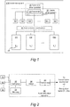
- FIG 1 is a schematic block diagram illustrating a fire swing door system 510 in which the inventive aspect of the present invention may be applied.
- the entrance system 10 comprises one or more swing door leafs D1 ... Dm, and an automatic door operator 30 for causing movements of the swing door leafs D1...Dm between closed and open positions.
- a transmission mechanism 40 conveys mechanical power from the automatic door operator 30 to the swing door leafs D1...Dm.
- Figure 2 illustrates one embodiment of the automatic door operator 30 in more detail.
- a control arrangement 20 is provided for the entrance system 10.
- the control arrangement 20 comprises a controller 32, which may be part of the automatic door operator 30 as seen in the embodiment of Figure 2 , but which may be a separate device in other embodiments.
- the control arrangement 20 also comprises a plurality of sensors S1... Sn. Each sensor is connected to the controller 32 by wired connections, wireless connections, or any combination thereof.
- each sensor is configured to monitor a respective zone Z1...Zn at the entrance system 10 for presence or activity of at least one person or object.
- the person may be an individual who is present at the entrance system 10, is approaching it or is departing from it.
- the object may, for instance, be an animal or an article in the vicinity of the entrance system 10, for instance brought by the aforementioned individual.
- Said zones Z1...Zn may be disposed so as to enable monitoring of persons or objects about to enter the entrance system 10 from both directions, i.e. both from the inside and outside, as well as persons or objects passing through the entrance system.
- the embodiment of the automatic door operator 30 shown in Figure 2 will now be described in more detail.
- the automatic door operator 30 may typically be arranged in conjunction with a frame or other structure which supports the swing door leafs D1...Dm for movements between closed and open positions, often as a concealed overhead installation in or at the frame or support structure.
- the automatic door operator 30 comprises a motor 34, typically an electrical motor, being connected to an internal transmission or gearbox 35.
- An output shaft of the transmission 35 rotates upon activation of the motor 34 and is connected to the external transmission mechanism 40.
- the external transmission mechanism translates the motion of the output shaft of the transmission 35 into an opening or a closing motion of one or more of the swing door leafs D1...Dm with respect to the frame or support structure.
- the controller 32 is configured for performing different functions of the automatic door operator 30 in the different operational states of the fire swing door system 510, using inter alia sensor input data from the plurality of sensors S1... Sn. Hence, the outputs of the plurality of sensors S1... Sn are connected to data inputs of the controller 32. At least some of the different functions performable by the controller 32 have the purpose of causing desired movements of the swing door leafs D1...Dm. To this end, the controller 32 has at least one control output connected to the motor 34 for controlling the actuation thereof.
- the sensors may for example be time of flight sensors, IR-sensors, radar (microwave) sensors.
- the sensors may be configured to monitor for example zones adapted to cover the entrance to the entrance system from both sides of the entrance system 10 and the area of the entrance system covering the trajectory of the one or more swing door leafs D1...Dm i.e. the opening and/or the closing trajectory of the one or more movable door members D1...Dm.
- the controller 32 may be implemented in any known controller technology, including but not limited to microcontroller, processor (e.g. PLC, CPU, DSP), FPGA, ASIC or any other suitable digital and/or analog circuitry capable of performing the intended functionality.
- processor e.g. PLC, CPU, DSP
- FPGA field-programmable gate array
- ASIC application-specific integrated circuit
- the controller 32 also has an associated memory 33.
- the memory 33 may be implemented in any known memory technology, including but not limited to E(E)PROM, S(D)RAM or flash memory. In some embodiments, the memory 33 may be integrated with or internal to the controller 32.
- the memory 33 may store program instruction for execution by the controller 32, as well as temporary and permanent data used by the controller 32.
- the automatic door operator 30 is for causing movements of the one or more swing door leafs D1...Dm between a closed position and an opened position. With advantage said automatic door operator 30 is configured to cause movements of the one or more swing door leaf D1...Dm between their said closed position and opened position and vice versa.
- a fire swing door system 510 is shown in a schematic top view in Figure 3 .
- the swing door system 510 comprises a swing door D1 being located between a lateral edge of a first wall 560 and an inner surface of a second wall 562 which is perpendicular to the first wall 560.
- the swing door D1 is supported for pivotal movement 550 around pivot points on or near the inner surface of the second wall 562.
- the first and second walls 560 and 562 are spaced apart; in between them an opening is formed which the swing door D1 either blocks (when the swing door is in closed position), or makes accessible for passage (when the swing door is in open position).
- An automatic door operator (not seen in Figure 6 but referred to as 30 in Figures 1 and 2 ) causes the movement 550 of the swing door D1.
- the one or more movable door members are one or more swing door leafs.
- the automatic door operator 30 is for causing movements of the swing door leaf D1 between the closed and opened position along an opening angle ⁇ in a direction of a first side of the fire swing door leaf D1.
- the fire swing door system 510 may comprise a plurality of sensors, each monitoring a respective zone Z1-Z4.
- the sensors themselves are not shown in Figure 3 , but they are generally mounted at or near ceiling level and/or at positions which allow them to monitor their respective zones Z1-Z4.
- a first sensor S1 is mounted at a first central positon in Figure 3 to monitor zone Z1.
- the first sensor S1 is a door presence sensor, and the purpose is to detect when a person or object occupies a space near the first side of the (door leaf of the) swing door leaf D1 when the swing door leaf D1 is being moved towards the open position during an opening state of the swing door system 510.
- the provision of the door presence sensor S1 will help avoiding a risk that the person or object will be hit by the first side of the swing door leaf D1 and/or be jammed between the first side of the swing door D1 and the second wall 562; a sensor detection in this situation will trigger abort and preferably reversal of the ongoing opening movement of the swing door leaf D1.
- a second sensor S2 is mounted at a second central positon in Figure 3 to monitor zone Z2.
- the second sensor S2 is a door presence sensor, just like the first sensor S1, and has the corresponding purpose - i.e. to detect when a person or object occupies a space near a second side of the swing door leaf D1 (the opposite side of the door leaf of the swing door leaf D1) when the swing door D1 is being moved towards the closed position during a closing state of the swing door system 510.
- the provision of the door presence sensor S2 will help avoiding a risk that the person or object will be hit by the second side of the swing door D1 and/or be jammed between the second side of the swing door leaf D1 and the first wall 560; a sensor detection in this situation will trigger abort and preferably reversal of the ongoing closing movement of the swing door leaf D1.
- the control arrangement 20 may be configured to control the movement of the swing door leaf D1 based on the obtained sensor data from S1 and S2.
- the sensors S1 and S2 may for be active IR (infrared) sensors, ultrasonic sensors, radar (microwave) sensors or time of flight sensors.
- a third sensor S3 may be mounted at an inner central positon in Figure 3 to monitor zone Z3.
- the third sensor S3 is an inner activity sensor, and the purpose is to detect when a person or object approaches the swing door system 510 from the inside of the premises.
- the provision of the inner activity sensor S3 will trigger the sliding door system 510, when being in a closed state or a closing state, to automatically switch to an opening state for opening the swing door leaf D1, and then make another switch to an open state when the swing door leaf D1 has reached its fully open position.
- a fourth sensor S4 may be mounted at an outer central positon in Figure 3 to monitor zone Z4.
- the fourth sensor S4 is an outer activity sensor, and the purpose is to detect when a person or object approaches the swing door system 510 from the outside of the premises. Similar to the inner activity sensor S3, the provision of the outer activity sensor S4 will trigger the swing door system 510, when being in its closed state or its closing state, to automatically switch to the opening state for opening the swing door leaf D1, and then make another switch to an open state when the swing door leaf D1 has reached its fully open position.
- the inner activity sensor S3 and the outer activity sensor S4 may be active IR (infrared) sensors, ultrasonic sensors, radar (microwave) sensors or time of flight sensors.
- a person or object P/O may be about to enter the entrance system 510 through the zone Z4.
- the sensor S4 is configured to monitor said zone Z4 and thus detects said person or object P/O.
- the control arrangement is configured to cause the entrance system 510 to enter the opening state in response to detecting the person or object P/O about to enter the entrance system through the zone Z4.
- the control arrangement may be configured to determine if the person or object P/O entering through risks to collide with the swing door leaf D1 based on the sensor input provided by the sensor S2 and control the automatic door operator so as to cause the entrance system 510 to switch from the closing state to the opening state in response to determining said risk. I.e. if such a risk has been identified, the control arrangement is configured to cause the entrance system to switch from the closing state to the opening state.
- the swing door leaf D1 may return towards its opened positions instead of risking a collision with the person or object passing through the entrance system 510.
- the fire swing door system 510 may be operated by means of a fire door opening switch 590.
- the fire door opening switch may be operatively connected to the control arrangement 20, i.e. the control arrangement 20 is operatively connected to the fire door opening switch 590.
- the control arrangement 20 may be configured to receive an opening command signal from said fire door opening switch 590 causing the automatic door operator 30 to initiate an opening cycle of the swing door leaf D1 in response to receiving said opening command.
- the fire door opening switch 590 may be integrated into the fire swing door system 510.
- the fire door opening switch 590 may be attached to the swing door leaf D1, the automatic door operator 30 or the frame of the fire swing door system 510.
- the fire door opening switch 590 may be in the form of a button switch. Upon pressing of said button switch the opening of the door leaf D1 is initiated.
- the opening of the swing door leaf D1 may be initiated from both sides of said door leaf D1 by means of activation of the respective switches 590.
- the fire swing door system 510 may be controlled both by means of the fire door opening switch 590 and the sensors S3 and S4 in combination with the sensors S1 and S2.
- the opening of the swing door leaf D1 may be initiated both by a person or object P/O being detected by the sensors S3 or S4 and the activation of the fire door opening switch 590.
- the first sensor S1 is configured to monitor the first zone Z1 for detecting when a person or object occupies a space near the first side of the swing door leaf D1 and the second sensor S2 is configured to monitor the second zone Z2 for detecting when a person or object occupies a space near the second side of the swing door leaf D2.
- the control arrangement 20 may thus configured to control the automatic door operator 30 based on sensor data obtained from said sensors.
- the fire swing door system may enter an emergency state which may trigger functionality stored in the memory to prevent risk for example a fire spreading.
- control arrangement 20 may be configured to cause the automatic door operator 30 to switch between operations in different modes as defined by a set of parameters in response to a fire alarm being active.
- the control arrangement 20 may be configured to cause the automatic door operator to operate in a first mode.
- the automatic door operator 30 is controlled based on sensor data obtained from the first sensor S1 and the second sensor S2.
- the first mode may represent a normal drive mode, i.e. a mode which is active any time when there is no emulated or real emergency.
- the automatic door operator 30 may not be controlled completely based on sensor data obtained from the first sensor S1 and the second S2 I in the first mode. As discussed above the automatic door operator 30 may further be controlled by means of the fire door opening switch 590 and/or sensor data obtained by the sensors S3 and S4 as well.
- the fire alarm signal may be generated externally or by the control arrangement 20 directly.
- the control arrangement 20 may thus be configured to receive or generate a fire alarm signal.
- the control arrangement 20 may be configured to cause the automatic door operator 30 to operate in a second mode in response to receiving or generating the fire alarm signal.
- the automatic door operator 30 is controlled based on sensor data obtained from the first sensor S1 and the control arrangement 20 is configured to disable control of said automatic door operator 30 based on sensor data obtained from the second sensor S2.
- control arrangement 20 may be configured to ignore detection of a person or object, i.e. a presence, in the second zone Z2 while controlling the automatic door operator based on detection based on detection of a person or object, i.e. presence, in the first zone Z1 in response to receiving or generating the fire alarm signal.
- control arrangement 20 is configured to cause the automatic door operator 30 to switch from the first mode to the second in response to receiving or generating the fire alarm signal.
- control arrangement 20 may be configured to disable control of the automatic door operator 30 by means of deactivating the second sensor S2 upon causing the automatic door operator 30 to operate in the second mode.
- control arrangement 20 may be configured to disable control of the automatic door operator 30 by means of disregarding the sensor data obtained from the second sensor S2 during operation of the automatic door operator 30 in the second mode.
- control arrangement 20 is configured to control the automatic door operator 30 solely based on the sensor data obtained from the first sensor S1 in the second mode.
- Said configuration allows for ignoring of detected objects on non-hinged side of the swing door leaf D1 while still allowing for automatic opening on the hinged side of the fire swing door leaf D1.
- Presence sensors such as the sensors S1 and S2 may not be capable of distinguishing a person or object from smoke. Thus, if the sensor S2 detects a presence due to smoke in the second zone Z2 in the event of the fire, it will result in the swing door leaf D1 being kept in an open position which may increase the risk for the fire or smoke spreading through the fire swing door system 510.
- the risk for the fire or smoke spreading through a fire swing door system is counteracted by means of deactivating all of the presence sensors of the fire swing door system when a fire alarm is active.
- the door leaf D1 is enabled and the door may automatically close after each opening due to the fire swing door system being provided with a self-closing mechanism.
- present configuration of the fire swing door system may cause a reduced risk of the fire spreading through the door due to the mitigation of the risk of the door opening due to smoke in the zone Z2 while automatic operating may still be performed on the hinged side of the door leaf D1 allowing inhabitants with disabilities to enter through the fire swing door system at least in one direction without requiring manual effort. Since a presence detected due to smoke in the zone Z1 will cause the door leaf D1 to being kept in a closed position so as to avoid collision with the perceived person or object due to the smoke, present configuration allows for easier passage without increasing the risk for spreading of smoke or fire through the fire swing door system.
- this allows for a safer configuration and testing process of the fire swing door where a fire alarm signal may be active when an operator is working on the fire swing door, since the first zone Z1 is still monitored by the sensor S1.
- the operator may position so as to perform the work standing in said first zone Z1, thereby not risking collision with the sliding door leaf D1 when a fire alarm is present.
- control arrangement 20 may be operatively connected to an external device configured to generate a fire alarm.
- an external device configured to generate a fire alarm.
- a device may for example be an external fire sensor, smoke sensor, temperature sensor or a fire alarm switch or similar arrangements and devices well-known in the arts.
- control arrangement 20 may be operatively connected to a fire sensor, smoke sensor, temperature sensor or fire alarm switch comprised in the fire swing door system 510, for example in the automatic door operator 30. Accordingly, the control arrangement 20 may be configured to generate the fire alarm signal in response to obtaining sensor data from the fire sensor indicative of a fire or a signal associated with manual activation of the fire alarm switch.
- control arrangement 20 may be operatively connected to an additional fire swing door system, said additional fire swing door system having a control arrangement configured to generate the fire alarm signal, whereby the control arrangement 20 may be configured to receive said fire alarm signal.
- the second mode may be associated with a lower kinetic energy of the door leaf, i.e. a lower kinetic energy of the door leaf in comparison to the first mode.
- the first mode is associated with the swing door leaf D1 being operated by the automatic door operator 30 with a higher kinetic energy
- the second mode is associated with the swing door leaf D1 being operated by the automatic door operator 30 with a comparatively lower kinetic energy.
- the lower kinetic energy in the event of an active fire alarm signal addresses a number of issues.
- the fire swing doors are often subjected to testing, service and calibration to ensure proper functioning in the case of an emergency.
- an operator has to be in the vicinity of the fire swing door system 510 when a simulated fire alarm signal is active.
- a reduced kinetic energy mode allows for tuning of the kinetic energy so as to not risk hurting the operator in case of a collision if the door opens or closes automatically.
- the automatic driving of the swing door leaf without sensor monitoring increases the risk for the swing door leaf to collide or pinch persons attempting to pass through the fire swing door leaf.
- the activation of a mode wherein the kinetic energy of the swing door leaf is reduced enables automatic control with safe passage even in smoky conditions.
- a fire swing door system which is in compliance with strict regulations regarding the maximum kinetic energy during automatic drive without functioning sensors as well as hospital standards regarding providing passage for patients even during smoky conditions is achieved.
- the risk for collision is further mitigated due the fire swing door system having a more predictable behavior in line with the common provisions of a general swing door system. This being due to for example an installation in a hospital not requiring a complete deactivation of the sensors in order to comply with hospital escape route regulations during a fire.
- the inertia I is thus proportional to a product of the door mass m and the width w of the swing door leaf.
- the second mode with a set desired kinetic energy may be achieved from obtaining and storing of the relevant parameters related to the dimensions of the swing door leaf as well as the drive of the swing door leaf.
- the kinetic energy of the swing door leaf may be kept low even during relatively high opening and closing speed of the swing door leaf. This is due to the inertia being distributed across the width of the swing door leaf in comparison to a sliding door leaf where the entire weight of the sliding door leaf is moved uniformly in a translational manner.
- a low kinetic energy mode in a swing door system may still provide a desirably fast closing and opening speed compared to a low kinetic energy mode for a sliding door system.
- the memory 33 may be configured to store parameters associated with the dimensions of the swing door leaf D1 as well as the weight of said swing door leaf D1.
- the control arrangement 20 may be configured to obtain said parameters.
- the fire swing door system 510 may further comprise an angular sensor for measuring the angular speed and/or angular acceleration of the swing door leaf D1.
- the angular sensor may be an encoder connected to the motor 34 of the automatic door operator 30.
- the torque M may be directly controllable by means of torque control.
- the dimensions and weight of the swing door leaf D1 may be obtained by means of obtaining of stored torque characteristics of the door operator 30 and running of a testing opening cycle with a set and predefined torque.
- the control arrangement 20 may be configured to control the speed of the door leaf D1, i.e. the angular speed ⁇ of said door leaf D1.
- the control arrangement 20 may be configured to switch to the second mode by setting a maximum angular speed ⁇ ⁇ ax of the second mode for the swing door leaf D1.
- the second mode may be associated with a maximum angular speed ⁇ ⁇ ax for the swing door leaf D1.
- the kinetic energy of the swing door leaf D1 in the second mode may be between 1,4 and 2 Joule.
- the kinetic energy of the fire swing door leaf D1 in the second mode may be between 1,5 and 1,8 Joule.
- the kinetic energy of the fire swing door leaf D1 in the second mode may be approximately 1,69 Joule.
- the closing force provided by the automatic door operator 30 may be between 100 Newton and 150 Newton in the second mode.
- the closing force provided by the automatic door operator 30 may be approximately 133 Newton in the second mode.
- Entrance systems may have a predefined "low-energy mode" associated with a lower kinetic energy.
- a low-energy mode may be selectable by an operator or may be automatically selected if there is a need for a lower energy consumption.
- the low-energy mode may also be associated with selective deactivation of sensors in order to further lower the energy consumption.
- the second mode may be such a low-energy mode, i.e. a preconfigured and manually selectable low energy mode of the automatic door operator 30.
- control arrangement 20 may be configured to obtain parameters associated with the low energy mode from the memory 33 connected to the controller 32 of the control arrangement 20.
- parameters may include any one of the following torque, opening and closing force, opening and closing speed.
- the setup and calibration of the fire swing door system may be substantially less complex, cumbersome and time consuming. Since, the fire swing door system may already have a low-energy mode used for other purposes, there will be no need for manually setting up the parameters for the second mode individually.
- Mechanical forced close arrangements are well-known for a person skilled in the arts.
- said mechanical forced close arrangements may be in the form of selectively activated spring or plummet arrangements.
- the forced close arrangements Upon activation by means of the control arrangement, the forced close arrangements provides a closing, preloaded force to so as close the fire swing door leaf D1.
- the forced close arrangement may either provide the sole closing force to the fire swing door leaf D1 or provide closing force in addition to the force directly provided by means of the control of the automatic door operator 30.
- the fire swing door system 510 may comprise such a mechanical forced close arrangement.
- the control arrangement 20 may be configured to activate said forced close arrangement close to the end of an opening cycle of the fire swing door leaf D1 so as to increase the closing speed of the fire swing door leaf D1 close to said end of the opening cycle.
- the opening cycle is herein defined as the cycle of the swing door leaf D1 moving from an initial closed position to an opened position and back to a closed position.
- the end of the opening cycle is herein defined as the part of the opening cycle associated with the swing door leaf D1 approaching the closed position after having been in an opened position.
- the forced close arrangement thereby serves to increase the closing speed so as to reduce the time which the swing door leaf D1 is not in the closed position when a fire alarm signal is active. Consequently, the risk for fire and smoke spreading by passing through the fire swing door system is reduced.
- the risk for the door leaf D1 to collide with a person or object is lower due to the short remaining trajectory before the door leaf D1 reaches its closed position.
- the risk for fire and smoke spreading is reduced in a manner which does not significantly increase the risk for persons or objects getting pinched.
- control arrangement 20 may be configured to activate the mechanical forced close arrangement when the opening angle ⁇ falls below a predefined angular value Y close to the end of the opening cycle.
- the opening angle is herein defined as an angle defined in the opening direction from the closed position of the swing door leaf D1.
- the predefined angular value Y is approximately 10 degrees.
- the fire swing door system 510 may comprise an energy storing arrangement, such as for example an energy harvest switch.
- the forced closed arrangement may thus be configured to be activated by means of the energy stored in the energy storing arrangement.
- FIG. 4 a method of operating the above described fire swing door 510 is depicted.
- the method comprises causing the automatic door operator 30 to operate in the first mode 1100.
- the automatic door operator 30 is controlled based on sensor data obtained from the first sensor S1 and the second sensor S2.
- the method further comprises receiving or generating a fire alarm signal and in response to receiving or generating the fire alarm signal causing the automatic door operator 30 to operate in the second mode.
- the automatic door operator 30 is controlled based on sensor data obtained from the first sensor S1 and control of the automatic door operator 30 based on sensor data obtained from the second sensor S2 is disabled.
- automatic drive based on sensor input is enabled on the first side of the swing door leaf.
- the second mode may be associated with a lower kinetic energy of the swing door leaf D1 in comparison the first mode.
- the kinetic energy of the fire swing door leaf D1 in the second mode may be between 1,5 and 1,8 Joule.
- the kinetic energy of the fire swing door leaf D1 in the second mode may be approximately 1,69 Joule.
- the closing force provided by the automatic door operator 30 may be between 100 Newton and 150 Newton in the second mode.
- the closing force provided by the automatic door operator 30 may be approximately 133 Newton in the second mode.
- the method comprises activating the forced close arrangement close to the end of an opening cycle of the fire swing door leaf D1 so as to increase the closing speed of the fire swing door leaf D1 close to said end of the opening cycle.
- the second mode is associated with a predetermined maximum angular speed ⁇ ⁇ ax of the second mode for the swing door leaf D1.
- the method further comprise causing the automatic door operator 30 to switch from the second mode to the first mode in response to the fire alarm no longer being generated or received.
- the fire alarm may be a continuously active signal.
- the control arrangement 20 may thus be configured to monitor the fire alarm signal so as to detect the fire alarm no longer being received or generated.
- the method further comprise causing the automatic door operator 30 to switch from the second mode to the first mode in response to receiving a fire alarm termination signal.
- the control arrangement 20 may be configured to receive a fire alarm termination signal. Said fire alarm termination signal may be externally generated.
Landscapes
- Business, Economics & Management (AREA)
- Emergency Management (AREA)
- Power-Operated Mechanisms For Wings (AREA)
- Special Wing (AREA)
Applications Claiming Priority (1)
| Application Number | Priority Date | Filing Date | Title |
|---|---|---|---|
| SE1830125 | 2018-04-16 |
Publications (1)
| Publication Number | Publication Date |
|---|---|
| EP3556982A1 true EP3556982A1 (fr) | 2019-10-23 |
Family
ID=66182471
Family Applications (1)
| Application Number | Title | Priority Date | Filing Date |
|---|---|---|---|
| EP19169353.0A Pending EP3556982A1 (fr) | 2018-04-16 | 2019-04-15 | Système d'entrée |
Country Status (1)
| Country | Link |
|---|---|
| EP (1) | EP3556982A1 (fr) |
Cited By (1)
| Publication number | Priority date | Publication date | Assignee | Title |
|---|---|---|---|---|
| EP4056798A1 (fr) * | 2021-03-11 | 2022-09-14 | dormakaba Deutschland GmbH | Procédé de commande d'une installation de porte |
Citations (3)
| Publication number | Priority date | Publication date | Assignee | Title |
|---|---|---|---|---|
| US4904880A (en) * | 1987-08-07 | 1990-02-27 | Yoshida Kogyo K.K. | Automatic door driving system |
| DE102015103756A1 (de) * | 2015-03-13 | 2016-09-15 | Gu Automatic Gmbh | Automatiktür, wie beispielsweise eine Schiebetür, eine Drehtür oder dergleichen |
| DE102015113228A1 (de) * | 2015-08-11 | 2017-02-16 | Gu Automatic Gmbh | Automatiktür, wie beispielsweise eine Schiebetür, eine Drehtür oder dergleichen |
-
2019
- 2019-04-15 EP EP19169353.0A patent/EP3556982A1/fr active Pending
Patent Citations (3)
| Publication number | Priority date | Publication date | Assignee | Title |
|---|---|---|---|---|
| US4904880A (en) * | 1987-08-07 | 1990-02-27 | Yoshida Kogyo K.K. | Automatic door driving system |
| DE102015103756A1 (de) * | 2015-03-13 | 2016-09-15 | Gu Automatic Gmbh | Automatiktür, wie beispielsweise eine Schiebetür, eine Drehtür oder dergleichen |
| DE102015113228A1 (de) * | 2015-08-11 | 2017-02-16 | Gu Automatic Gmbh | Automatiktür, wie beispielsweise eine Schiebetür, eine Drehtür oder dergleichen |
Cited By (2)
| Publication number | Priority date | Publication date | Assignee | Title |
|---|---|---|---|---|
| EP4056798A1 (fr) * | 2021-03-11 | 2022-09-14 | dormakaba Deutschland GmbH | Procédé de commande d'une installation de porte |
| DE102021105912A1 (de) | 2021-03-11 | 2022-09-15 | Dormakaba Deutschland Gmbh | Verfahren zur steuerung einer türanlage |
Similar Documents
| Publication | Publication Date | Title |
|---|---|---|
| EP3610112B1 (fr) | Agencement de commande pour un système d'entrée comprenant un ou plusieurs éléments de porte mobiles | |
| AU2017371116A1 (en) | Automatic door operator for a swing door assembly | |
| US11536078B2 (en) | Configuration of entrance systems having one or more movable door members | |
| EP3556982A1 (fr) | Système d'entrée | |
| US7183732B2 (en) | Motorized barrier operator system for controlling a stopped, partially open barrier and related methods | |
| CN113994063B (zh) | 在紧急模式中具有改进的可操作性的基于摆动门的入口系统 | |
| EP3464769B1 (fr) | Actionneur de porte battante | |
| CN113939640A (zh) | 具有连杆减小曲线的自动识别的基于摆动门的入口系统 | |
| US11408221B2 (en) | Entrance system | |
| US11761253B2 (en) | Finger pinch protection for an entrance system | |
| US11594089B2 (en) | Touchless motion sensor systems for performing directional detection and for providing access control | |
| CN113825886B (zh) | 用于在开启位置和关闭位置之间的摆动路径上移动摆动门扇的摆动门操作器、摆动门及具有摆动门的房间 | |
| DE102006017070A1 (de) | Sicherheitsvorrichtung | |
| KR101316098B1 (ko) | 소방용 창문 개폐장치, 및 제어방법 | |
| WO2023094343A1 (fr) | Système de porte tournante | |
| KR101581408B1 (ko) | 자동 방범창 | |
| KR20230046509A (ko) | 방화문용 제어장치 |
Legal Events
| Date | Code | Title | Description |
|---|---|---|---|
| PUAI | Public reference made under article 153(3) epc to a published international application that has entered the european phase |
Free format text: ORIGINAL CODE: 0009012 |
|
| STAA | Information on the status of an ep patent application or granted ep patent |
Free format text: STATUS: THE APPLICATION HAS BEEN PUBLISHED |
|
| AK | Designated contracting states |
Kind code of ref document: A1 Designated state(s): AL AT BE BG CH CY CZ DE DK EE ES FI FR GB GR HR HU IE IS IT LI LT LU LV MC MK MT NL NO PL PT RO RS SE SI SK SM TR |
|
| AX | Request for extension of the european patent |
Extension state: BA ME |
|
| STAA | Information on the status of an ep patent application or granted ep patent |
Free format text: STATUS: REQUEST FOR EXAMINATION WAS MADE |
|
| 17P | Request for examination filed |
Effective date: 20200423 |
|
| RBV | Designated contracting states (corrected) |
Designated state(s): AL AT BE BG CH CY CZ DE DK EE ES FI FR GB GR HR HU IE IS IT LI LT LU LV MC MK MT NL NO PL PT RO RS SE SI SK SM TR |
|
| STAA | Information on the status of an ep patent application or granted ep patent |
Free format text: STATUS: EXAMINATION IS IN PROGRESS |
|
| STAA | Information on the status of an ep patent application or granted ep patent |
Free format text: STATUS: EXAMINATION IS IN PROGRESS |
|
| 17Q | First examination report despatched |
Effective date: 20201117 |