EP3556939A1 - Drone takeoff and landing system - Google Patents
Drone takeoff and landing system Download PDFInfo
- Publication number
- EP3556939A1 EP3556939A1 EP17881158.4A EP17881158A EP3556939A1 EP 3556939 A1 EP3556939 A1 EP 3556939A1 EP 17881158 A EP17881158 A EP 17881158A EP 3556939 A1 EP3556939 A1 EP 3556939A1
- Authority
- EP
- European Patent Office
- Prior art keywords
- drone
- landing
- electromagnet
- hole
- extension member
- Prior art date
- Legal status (The legal status is an assumption and is not a legal conclusion. Google has not performed a legal analysis and makes no representation as to the accuracy of the status listed.)
- Pending
Links
- 239000004020 conductor Substances 0.000 claims description 39
- 230000006698 induction Effects 0.000 claims description 9
- 239000013013 elastic material Substances 0.000 claims description 3
- 230000000694 effects Effects 0.000 description 11
- 230000000284 resting effect Effects 0.000 description 7
- XEEYBQQBJWHFJM-UHFFFAOYSA-N Iron Chemical group [Fe] XEEYBQQBJWHFJM-UHFFFAOYSA-N 0.000 description 4
- BASFCYQUMIYNBI-UHFFFAOYSA-N platinum Chemical compound [Pt] BASFCYQUMIYNBI-UHFFFAOYSA-N 0.000 description 4
- RYGMFSIKBFXOCR-UHFFFAOYSA-N Copper Chemical compound [Cu] RYGMFSIKBFXOCR-UHFFFAOYSA-N 0.000 description 2
- BQCADISMDOOEFD-UHFFFAOYSA-N Silver Chemical compound [Ag] BQCADISMDOOEFD-UHFFFAOYSA-N 0.000 description 2
- HCHKCACWOHOZIP-UHFFFAOYSA-N Zinc Chemical compound [Zn] HCHKCACWOHOZIP-UHFFFAOYSA-N 0.000 description 2
- 229910052802 copper Inorganic materials 0.000 description 2
- 239000010949 copper Substances 0.000 description 2
- 230000005674 electromagnetic induction Effects 0.000 description 2
- PCHJSUWPFVWCPO-UHFFFAOYSA-N gold Chemical compound [Au] PCHJSUWPFVWCPO-UHFFFAOYSA-N 0.000 description 2
- 229910052737 gold Inorganic materials 0.000 description 2
- 239000010931 gold Substances 0.000 description 2
- 239000011133 lead Substances 0.000 description 2
- QSHDDOUJBYECFT-UHFFFAOYSA-N mercury Chemical compound [Hg] QSHDDOUJBYECFT-UHFFFAOYSA-N 0.000 description 2
- 229910052753 mercury Inorganic materials 0.000 description 2
- 238000000034 method Methods 0.000 description 2
- 229910052697 platinum Inorganic materials 0.000 description 2
- 229910052709 silver Inorganic materials 0.000 description 2
- 239000004332 silver Substances 0.000 description 2
- 238000004804 winding Methods 0.000 description 2
- 229910052725 zinc Inorganic materials 0.000 description 2
- 239000011701 zinc Substances 0.000 description 2
- 230000003247 decreasing effect Effects 0.000 description 1
- 238000010304 firing Methods 0.000 description 1
- 238000012986 modification Methods 0.000 description 1
- 230000004048 modification Effects 0.000 description 1
Images


Classifications
-
- B—PERFORMING OPERATIONS; TRANSPORTING
- B64—AIRCRAFT; AVIATION; COSMONAUTICS
- B64C—AEROPLANES; HELICOPTERS
- B64C39/00—Aircraft not otherwise provided for
- B64C39/02—Aircraft not otherwise provided for characterised by special use
- B64C39/024—Aircraft not otherwise provided for characterised by special use of the remote controlled vehicle type, i.e. RPV
-
- B—PERFORMING OPERATIONS; TRANSPORTING
- B60—VEHICLES IN GENERAL
- B60L—PROPULSION OF ELECTRICALLY-PROPELLED VEHICLES; SUPPLYING ELECTRIC POWER FOR AUXILIARY EQUIPMENT OF ELECTRICALLY-PROPELLED VEHICLES; ELECTRODYNAMIC BRAKE SYSTEMS FOR VEHICLES IN GENERAL; MAGNETIC SUSPENSION OR LEVITATION FOR VEHICLES; MONITORING OPERATING VARIABLES OF ELECTRICALLY-PROPELLED VEHICLES; ELECTRIC SAFETY DEVICES FOR ELECTRICALLY-PROPELLED VEHICLES
- B60L53/00—Methods of charging batteries, specially adapted for electric vehicles; Charging stations or on-board charging equipment therefor; Exchange of energy storage elements in electric vehicles
- B60L53/10—Methods of charging batteries, specially adapted for electric vehicles; Charging stations or on-board charging equipment therefor; Exchange of energy storage elements in electric vehicles characterised by the energy transfer between the charging station and the vehicle
- B60L53/12—Inductive energy transfer
-
- B—PERFORMING OPERATIONS; TRANSPORTING
- B60—VEHICLES IN GENERAL
- B60L—PROPULSION OF ELECTRICALLY-PROPELLED VEHICLES; SUPPLYING ELECTRIC POWER FOR AUXILIARY EQUIPMENT OF ELECTRICALLY-PROPELLED VEHICLES; ELECTRODYNAMIC BRAKE SYSTEMS FOR VEHICLES IN GENERAL; MAGNETIC SUSPENSION OR LEVITATION FOR VEHICLES; MONITORING OPERATING VARIABLES OF ELECTRICALLY-PROPELLED VEHICLES; ELECTRIC SAFETY DEVICES FOR ELECTRICALLY-PROPELLED VEHICLES
- B60L53/00—Methods of charging batteries, specially adapted for electric vehicles; Charging stations or on-board charging equipment therefor; Exchange of energy storage elements in electric vehicles
- B60L53/30—Constructional details of charging stations
- B60L53/31—Charging columns specially adapted for electric vehicles
-
- B—PERFORMING OPERATIONS; TRANSPORTING
- B60—VEHICLES IN GENERAL
- B60L—PROPULSION OF ELECTRICALLY-PROPELLED VEHICLES; SUPPLYING ELECTRIC POWER FOR AUXILIARY EQUIPMENT OF ELECTRICALLY-PROPELLED VEHICLES; ELECTRODYNAMIC BRAKE SYSTEMS FOR VEHICLES IN GENERAL; MAGNETIC SUSPENSION OR LEVITATION FOR VEHICLES; MONITORING OPERATING VARIABLES OF ELECTRICALLY-PROPELLED VEHICLES; ELECTRIC SAFETY DEVICES FOR ELECTRICALLY-PROPELLED VEHICLES
- B60L53/00—Methods of charging batteries, specially adapted for electric vehicles; Charging stations or on-board charging equipment therefor; Exchange of energy storage elements in electric vehicles
- B60L53/30—Constructional details of charging stations
- B60L53/35—Means for automatic or assisted adjustment of the relative position of charging devices and vehicles
- B60L53/36—Means for automatic or assisted adjustment of the relative position of charging devices and vehicles by positioning the vehicle
-
- B—PERFORMING OPERATIONS; TRANSPORTING
- B60—VEHICLES IN GENERAL
- B60L—PROPULSION OF ELECTRICALLY-PROPELLED VEHICLES; SUPPLYING ELECTRIC POWER FOR AUXILIARY EQUIPMENT OF ELECTRICALLY-PROPELLED VEHICLES; ELECTRODYNAMIC BRAKE SYSTEMS FOR VEHICLES IN GENERAL; MAGNETIC SUSPENSION OR LEVITATION FOR VEHICLES; MONITORING OPERATING VARIABLES OF ELECTRICALLY-PROPELLED VEHICLES; ELECTRIC SAFETY DEVICES FOR ELECTRICALLY-PROPELLED VEHICLES
- B60L53/00—Methods of charging batteries, specially adapted for electric vehicles; Charging stations or on-board charging equipment therefor; Exchange of energy storage elements in electric vehicles
- B60L53/30—Constructional details of charging stations
- B60L53/35—Means for automatic or assisted adjustment of the relative position of charging devices and vehicles
- B60L53/38—Means for automatic or assisted adjustment of the relative position of charging devices and vehicles specially adapted for charging by inductive energy transfer
-
- B—PERFORMING OPERATIONS; TRANSPORTING
- B64—AIRCRAFT; AVIATION; COSMONAUTICS
- B64C—AEROPLANES; HELICOPTERS
- B64C39/00—Aircraft not otherwise provided for
- B64C39/02—Aircraft not otherwise provided for characterised by special use
-
- B—PERFORMING OPERATIONS; TRANSPORTING
- B64—AIRCRAFT; AVIATION; COSMONAUTICS
- B64F—GROUND OR AIRCRAFT-CARRIER-DECK INSTALLATIONS SPECIALLY ADAPTED FOR USE IN CONNECTION WITH AIRCRAFT; DESIGNING, MANUFACTURING, ASSEMBLING, CLEANING, MAINTAINING OR REPAIRING AIRCRAFT, NOT OTHERWISE PROVIDED FOR; HANDLING, TRANSPORTING, TESTING OR INSPECTING AIRCRAFT COMPONENTS, NOT OTHERWISE PROVIDED FOR
- B64F1/00—Ground or aircraft-carrier-deck installations
- B64F1/007—Helicopter portable landing pads
-
- B—PERFORMING OPERATIONS; TRANSPORTING
- B64—AIRCRAFT; AVIATION; COSMONAUTICS
- B64F—GROUND OR AIRCRAFT-CARRIER-DECK INSTALLATIONS SPECIALLY ADAPTED FOR USE IN CONNECTION WITH AIRCRAFT; DESIGNING, MANUFACTURING, ASSEMBLING, CLEANING, MAINTAINING OR REPAIRING AIRCRAFT, NOT OTHERWISE PROVIDED FOR; HANDLING, TRANSPORTING, TESTING OR INSPECTING AIRCRAFT COMPONENTS, NOT OTHERWISE PROVIDED FOR
- B64F1/00—Ground or aircraft-carrier-deck installations
- B64F1/02—Arresting gear; Liquid barriers
-
- B—PERFORMING OPERATIONS; TRANSPORTING
- B64—AIRCRAFT; AVIATION; COSMONAUTICS
- B64F—GROUND OR AIRCRAFT-CARRIER-DECK INSTALLATIONS SPECIALLY ADAPTED FOR USE IN CONNECTION WITH AIRCRAFT; DESIGNING, MANUFACTURING, ASSEMBLING, CLEANING, MAINTAINING OR REPAIRING AIRCRAFT, NOT OTHERWISE PROVIDED FOR; HANDLING, TRANSPORTING, TESTING OR INSPECTING AIRCRAFT COMPONENTS, NOT OTHERWISE PROVIDED FOR
- B64F1/00—Ground or aircraft-carrier-deck installations
- B64F1/12—Anchoring
- B64F1/125—Mooring or ground handling devices for helicopters
-
- B—PERFORMING OPERATIONS; TRANSPORTING
- B64—AIRCRAFT; AVIATION; COSMONAUTICS
- B64U—UNMANNED AERIAL VEHICLES [UAV]; EQUIPMENT THEREFOR
- B64U50/00—Propulsion; Power supply
- B64U50/30—Supply or distribution of electrical power
- B64U50/37—Charging when not in flight
- B64U50/38—Charging when not in flight by wireless transmission
-
- B—PERFORMING OPERATIONS; TRANSPORTING
- B64—AIRCRAFT; AVIATION; COSMONAUTICS
- B64U—UNMANNED AERIAL VEHICLES [UAV]; EQUIPMENT THEREFOR
- B64U60/00—Undercarriages
- B64U60/30—Undercarriages detachable from the body
-
- B—PERFORMING OPERATIONS; TRANSPORTING
- B64—AIRCRAFT; AVIATION; COSMONAUTICS
- B64U—UNMANNED AERIAL VEHICLES [UAV]; EQUIPMENT THEREFOR
- B64U70/00—Launching, take-off or landing arrangements
- B64U70/30—Launching, take-off or landing arrangements for capturing UAVs in flight by ground or sea-based arresting gear, e.g. by a cable or a net
-
- E—FIXED CONSTRUCTIONS
- E01—CONSTRUCTION OF ROADS, RAILWAYS, OR BRIDGES
- E01F—ADDITIONAL WORK, SUCH AS EQUIPPING ROADS OR THE CONSTRUCTION OF PLATFORMS, HELICOPTER LANDING STAGES, SIGNS, SNOW FENCES, OR THE LIKE
- E01F3/00—Landing stages for helicopters, e.g. located above buildings
-
- B—PERFORMING OPERATIONS; TRANSPORTING
- B60—VEHICLES IN GENERAL
- B60L—PROPULSION OF ELECTRICALLY-PROPELLED VEHICLES; SUPPLYING ELECTRIC POWER FOR AUXILIARY EQUIPMENT OF ELECTRICALLY-PROPELLED VEHICLES; ELECTRODYNAMIC BRAKE SYSTEMS FOR VEHICLES IN GENERAL; MAGNETIC SUSPENSION OR LEVITATION FOR VEHICLES; MONITORING OPERATING VARIABLES OF ELECTRICALLY-PROPELLED VEHICLES; ELECTRIC SAFETY DEVICES FOR ELECTRICALLY-PROPELLED VEHICLES
- B60L2200/00—Type of vehicles
- B60L2200/10—Air crafts
-
- B—PERFORMING OPERATIONS; TRANSPORTING
- B64—AIRCRAFT; AVIATION; COSMONAUTICS
- B64U—UNMANNED AERIAL VEHICLES [UAV]; EQUIPMENT THEREFOR
- B64U10/00—Type of UAV
- B64U10/10—Rotorcrafts
- B64U10/13—Flying platforms
- B64U10/14—Flying platforms with four distinct rotor axes, e.g. quadcopters
-
- B—PERFORMING OPERATIONS; TRANSPORTING
- B64—AIRCRAFT; AVIATION; COSMONAUTICS
- B64U—UNMANNED AERIAL VEHICLES [UAV]; EQUIPMENT THEREFOR
- B64U2201/00—UAVs characterised by their flight controls
- B64U2201/20—Remote controls
-
- B—PERFORMING OPERATIONS; TRANSPORTING
- B64—AIRCRAFT; AVIATION; COSMONAUTICS
- B64U—UNMANNED AERIAL VEHICLES [UAV]; EQUIPMENT THEREFOR
- B64U50/00—Propulsion; Power supply
- B64U50/10—Propulsion
- B64U50/19—Propulsion using electrically powered motors
-
- B—PERFORMING OPERATIONS; TRANSPORTING
- B64—AIRCRAFT; AVIATION; COSMONAUTICS
- B64U—UNMANNED AERIAL VEHICLES [UAV]; EQUIPMENT THEREFOR
- B64U50/00—Propulsion; Power supply
- B64U50/30—Supply or distribution of electrical power
- B64U50/34—In-flight charging
-
- B—PERFORMING OPERATIONS; TRANSPORTING
- B64—AIRCRAFT; AVIATION; COSMONAUTICS
- B64U—UNMANNED AERIAL VEHICLES [UAV]; EQUIPMENT THEREFOR
- B64U70/00—Launching, take-off or landing arrangements
- B64U70/80—Vertical take-off or landing, e.g. using rockets
-
- B—PERFORMING OPERATIONS; TRANSPORTING
- B64—AIRCRAFT; AVIATION; COSMONAUTICS
- B64U—UNMANNED AERIAL VEHICLES [UAV]; EQUIPMENT THEREFOR
- B64U70/00—Launching, take-off or landing arrangements
- B64U70/90—Launching from or landing on platforms
- B64U70/97—Means for guiding the UAV to a specific location on the platform, e.g. platform structures preventing landing off-centre
-
- B—PERFORMING OPERATIONS; TRANSPORTING
- B64—AIRCRAFT; AVIATION; COSMONAUTICS
- B64U—UNMANNED AERIAL VEHICLES [UAV]; EQUIPMENT THEREFOR
- B64U80/00—Transport or storage specially adapted for UAVs
-
- B—PERFORMING OPERATIONS; TRANSPORTING
- B64—AIRCRAFT; AVIATION; COSMONAUTICS
- B64U—UNMANNED AERIAL VEHICLES [UAV]; EQUIPMENT THEREFOR
- B64U80/00—Transport or storage specially adapted for UAVs
- B64U80/20—Transport or storage specially adapted for UAVs with arrangements for servicing the UAV
- B64U80/25—Transport or storage specially adapted for UAVs with arrangements for servicing the UAV for recharging batteries; for refuelling
-
- Y—GENERAL TAGGING OF NEW TECHNOLOGICAL DEVELOPMENTS; GENERAL TAGGING OF CROSS-SECTIONAL TECHNOLOGIES SPANNING OVER SEVERAL SECTIONS OF THE IPC; TECHNICAL SUBJECTS COVERED BY FORMER USPC CROSS-REFERENCE ART COLLECTIONS [XRACs] AND DIGESTS
- Y02—TECHNOLOGIES OR APPLICATIONS FOR MITIGATION OR ADAPTATION AGAINST CLIMATE CHANGE
- Y02T—CLIMATE CHANGE MITIGATION TECHNOLOGIES RELATED TO TRANSPORTATION
- Y02T50/00—Aeronautics or air transport
- Y02T50/50—On board measures aiming to increase energy efficiency
-
- Y—GENERAL TAGGING OF NEW TECHNOLOGICAL DEVELOPMENTS; GENERAL TAGGING OF CROSS-SECTIONAL TECHNOLOGIES SPANNING OVER SEVERAL SECTIONS OF THE IPC; TECHNICAL SUBJECTS COVERED BY FORMER USPC CROSS-REFERENCE ART COLLECTIONS [XRACs] AND DIGESTS
- Y02—TECHNOLOGIES OR APPLICATIONS FOR MITIGATION OR ADAPTATION AGAINST CLIMATE CHANGE
- Y02T—CLIMATE CHANGE MITIGATION TECHNOLOGIES RELATED TO TRANSPORTATION
- Y02T90/00—Enabling technologies or technologies with a potential or indirect contribution to GHG emissions mitigation
- Y02T90/10—Technologies relating to charging of electric vehicles
- Y02T90/12—Electric charging stations
Definitions
- Example embodiments relate to a drone takeoff and landing system.
- a drone refers to an unmanned aerial vehicle or a helicopter-shaped flying vehicle that flies or steers through induction of radio waves without a human pilot or operator, and is initially used for military purposes.
- a drone is currently used for commercial purposes, in addition to the military purposes. Thus, research has been actively conducted on drones to be used for such various purposes.
- An aspect provides a drone takeoff and landing system that may prevent a collision between drones when the drones land on a landing stand, and prevent a collision between drones without being affected when power of a drone is blocked.
- An aspect also provides a drone takeoff and landing system that may accommodate a plurality of drones and facilitate takeoff, landing, and transportation of the drones.
- An aspect also provides a drone takeoff and landing system that may adjust a takeoff or landing speed of a drone, thereby enabling the drone to take off fast from a landing stand and land softly on the landing stand, and also enabling the drone to be wirelessly charged while the drone is resting on the landing stand.
- An aspect also provides a drone takeoff and landing system that may generate an eddy current or a magnetic field between a drone and a landing stand and adjust a takeoff or landing speed of the drone, thereby enabling the drone to take off fast from the landing stand and land softly on the landing stand.
- An aspect also provides a drone takeoff and landing system that may generate an eddy current or a magnetic field between a drone and a landing stand, thereby enabling the drone to be wirelessly charged while the drone is resting on the landing stand.
- An aspect also provides a drone takeoff and landing system that may include a landing module attachable to or detachable from an existing drone and a landing stand, thereby achieving same effects as described above from the existing drone without a through-hole in a main body of the existing drone.
- a drone takeoff and landing system including a drone including a through-hole, and a landing stand including an extension member configured to pass through the through-hole.
- a drone including a through-hole
- a landing stand including an extension member configured to pass through the through-hole.
- an eddy current may be generated between the through-hole and the extension member, and magnetic braking may occur in the drone.
- a magnetic body may be disposed on a surface of the through-hole, and the extension member may be formed as a nonferrous conductor or include a nonferrous conductor element provided on a surface of the extension member.
- the eddy current may be generated between the magnetic body and the nonferrous conductor.
- a nonferrous conductor element may be disposed on the surface of the through-hole, and a magnetic body may be disposed on the surface of the extension member.
- the eddy current may be generated between the magnetic body and the nonferrous conductor element.
- the drone may include a main body including the through-hole, and a thruster provided outside the main body.
- the landing stand may include a landing pad, on one surface of which the extension member having a column shape is provided.
- the drone takeoff and landing system may include a plurality of drones.
- a length of the extension member may be set to be greater than a total height of the drones.
- the extension member may pass through respective through-holes of the drones, and the drones may be stacked in sequential order on the landing stand.
- the landing stand may further include a cover provided on the landing pad to protect the drones stacked on the landing stand.
- the through-hole may be formed as a plurality of through-holes.
- the extension member may be provided in a number corresponding to the number of the through-holes.
- the drone takeoff and landing system may include the drone including the through-hole, and the landing stand including the extension member configured to pass through the through-hole.
- a first electromagnet may be disposed in the through-hole, and a second electromagnet may be disposed in the extension member.
- a magnetic field of the first electromagnet and the second electromagnet may be controlled to control a takeoff or landing speed of the drone or wirelessly charge the drone.
- Each of the first electromagnet and the second electromagnet may be disposed to form a radial magnetic field in a direction vertical to a length direction of the through-hole and the extension member, respectively.
- a polarity of the first electromagnet and the second electromagnet may be controlled to increase the takeoff speed of the drone when the drone takes off from the landing stand, or to decrease the landing speed of the drone when the drone lands on the landing stand.
- the drone may be wirelessly charged by magnetic induction between the first electromagnet and the second electromagnet.
- Each of the first electromagnet and the second electromagnet may be disposed to form an axial magnetic field in a direction horizontal to the length direction of the through-hole and the extension member, respectively.
- the polarity of the first electromagnet and the second electromagnet may be controlled to increase the takeoff speed of the drone when the drone takes off from the landing stand, or to decrease the landing speed of the drone when the drone lands on the landing stand.
- the drone may be wirelessly charged by magnetic induction between the first electromagnet and the second electromagnet.
- a drone takeoff and landing system including a drone including a through-hole, and a landing stand including a landing pad and an extension member provided on one surface of the landing pad and configured to pass through the through-hole.
- the through-hole may be formed on a side surface of a main body of the drone such that one surface of the through-hole is opened in a direction towards an outside of the main body.
- the extension member of the landing stand may be configured to move vertically from the landing pad, and configured to move selectively upwards or downwards when the drone takes off or lands.
- the through-hole may be formed as a plurality of through-holes, and the extension member may be provided in a number corresponding to the number of the through-holes.
- an eddy current may be generated between the through-hole and the extension member, and magnetic braking or wireless charging may occur in the drone.
- a magnetic body or an electromagnet may be disposed in the through-hole, and a nonferrous conductor may be disposed in the extension member.
- the eddy current may be generated between the magnetic body or the electromagnet, and the nonferrous conductor.
- a nonferrous conductor may be disposed in the through-hole, and a magnetic body or an electromagnet may be disposed in the extension member.
- the eddy current may be generated between the magnetic body or the electromagnet, and the nonferrous conductor.
- a first electromagnet may be disposed in the through-hole, and a second electromagnet may be disposed in the extension member.
- a magnetic field of the first electromagnet and the second electromagnet may be controlled to control a takeoff or landing speed of the drone or wirelessly charge the drone.
- a drone takeoff and landing system including a landing module attachable to or detachable from a drone and including a through-hole, and a landing stand including a landing pad and an extension member provided on one surface of the landing pad and configured to pass through the through-hole.
- the landing module may include a plurality of pass-through members each including a through-hole, and a connection member configured to connect the pass-through members and attachable to and detachable from the drone.
- an eddy current or a magnetic field may be generated between the through-hole and the extension member when the extension member passes through the through-hole, to control a speed of the drone or wirelessly charge the drone.
- connection member may be formed of an elastic material such that a length thereof is adjustable, or a length of the connection member may be adjustable through screw tightening.
- a magnetic body or an electromagnet may be disposed in one of the through-hole and the extension member, and a nonferrous conductor may be disposed in the other.
- the eddy current may be generated between the magnetic body or the electromagnet, and the nonferrous conductor, and magnetic braking or wireless charging may occur in the drone.
- a first electromagnet may be disposed in the through-hole, and a second electromagnet may be disposed in the extension member.
- a magnetic field of the first electromagnet and the second electromagnet may be controlled to control a takeoff or landing speed of the drone or wirelessly charge the drone.
- a drone takeoff and landing system may prevent a collision between drones when the drones land on a landing stand, and prevent a collision between drones without being affected when power of a drone is blocked.
- the drone takeoff and landing system may accommodate a plurality of drones, and facilitate takeoff, landing, and transportation of the drones.
- the drone takeoff and landing system may adjust a takeoff or landing speed of a drone, and thus enable the drone to take off fast from a landing stand and land softly on the landing stand, and also enable the drone to be wirelessly charged while the drone is resting on the landing stand.
- the drone takeoff and landing system may generate an eddy current or a magnetic field between a drone and a landing stand and adjust a takeoff or landing speed of the drone, and thus may enable the drone to take off fast from the landing stand and land softly on the landing stand.
- the drone takeoff and landing system may generate an eddy current or a magnetic field between a drone and a landing stand, and thus enable the drone to be wirelessly charged while the drone is resting on the landing stand.
- a drone takeoff and landing system may include a landing module attachable to or detachable from an existing drone and a landing stand, thereby achieving same effects as described above from the existing drone without a through-hole in a main body of the existing drone.
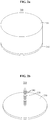
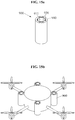
- FIGS. 1a and 1b illustrate a drone according to an example embodiment.
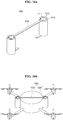
- FIGS. 2a and 2b illustrate a landing stand according to an example embodiment.
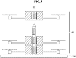
- FIG. 3 illustrates a drone takeoff and landing system according to an example embodiment.
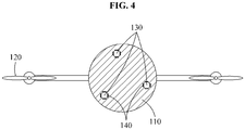
- FIGS. 4 and 5 illustrate a drone takeoff and landing system including a plurality of through-holes and a plurality of extension members according to an example embodiment.
- FIGS. 6a and 6b illustrate a drone forming a radial magnetic field according to an example embodiment.
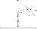
- FIG. 7 illustrates a landing stand forming a radial magnetic field according to an example embodiment.
- FIGS. 8a and 8b illustrate a drone forming an axial magnetic field according to an example embodiment.
- FIGS. 10 and 11 illustrate a drone according a modified example embodiment.
- FIG. 12 illustrates a landing stand according a modified example embodiment.
- FIGS. 13 and 14 illustrate a drone takeoff and landing system according a modified example embodiment.
- FIGS. 15a through 17b illustrate a landing module of a drone takeoff and landing system, and a drone to which the landing module is attached according to another example embodiment.
- a drone takeoff and landing system 10 includes a drone 100 including a through-hole 130, and a landing stand 200 including an extension member 220 configured to pass through the through-hole 130 of the drone 100.
- a drone 100 including a through-hole 130
- a landing stand 200 including an extension member 220 configured to pass through the through-hole 130 of the drone 100.
- an eddy current may be generated between the through-hole 130 and the extension member 220, and thus magnetic braking may occur in the drone 100.
- the drone 100 includes a main body 110, and a thruster 120 provided outside the main body 110.
- the through-hole 130 is formed in a portion of the main body 110 and configured to pass through the main body 110 from top to bottom.
- the through-hole 130 may be formed in a cylindrical shape.
- a shape of the through-hole 130 is not limited to the cylindrical shape, but a polygonal column shape such as a triangular prism shape and a rectangular column shape may also be applied as needed.
- a magnetic body 140 is disposed on a surface of the through-hole 130 of the drone 100.
- one or more magnetic bodies 140 may be disposed, separately from each other at regular intervals, on the surface of the through-hole 130.
- the magnetic body 140 may be formed to surround the entire surface of the through-hole 130.
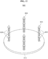
- the landing stand 200 includes a landing pad 210, and the extension member 220 provided on one surface of the landing pad 210 and formed in a column shape.
- the extension member 220 may be formed in a cylindrical shape, and also in a polygonal column shape such as a triangular prism shape and a rectangular column shape as needed.
- the extension member 220 may be formed as a nonferrous conductor.
- a plurality of nonferrous conductor elements 240 may be additionally disposed on a surface of the extension member 220.
- the nonferrous conductor copper, lead, zinc, gold, platinum, mercury, silver, and the like may be used.
- a cross-sectional area of the landing pad 210 may be set to be greater than an entire cross-sectional area of the drone 100 to be received by the landing stand 200.
- the landing stand 200 further includes a cover 230 provided on the landing pad 210 and configured to protect the drone 100 stacked on the landing stand 200. In such a case, the cover 230 may be closely connected to the landing pad 210 to seal or cover the drone 100 as a whole.
- the cross-sectional area of the landing pad 210 may be set to be smaller than the entire cross-sectional area of the drone 100 to be received by the landing stand 200.
- the cover 230 may be formed in an open type, and fixed to the landing stand 200 by a fixing element provided at an end of the extension member 220.
- the drone takeoff and landing system 10 includes a plurality of drones 100, and a length of the extension member 220 of the landing stand 200 is set to be longer than a total height of the drones 100.
- the drones 100 may be sequentially stacked on the landing stand 200.
- an eddy current may be generated between the magnetic body 140 disposed on the surface of the through-hole 130 of the drone 100 and the nonferrous conductor elements 240 disposed on the surface of the extension member 220 of the landing stand 200.
- the eddy current refers to a current, such as an alternating current, which is generated by electromagnetic induction of a conductor in a magnetic field that changes with time.
- a force generated by the eddy current may be used to generate a magnetic braking effect.
- the magnetic braking effect may be generated by the eddy current, thereby preventing a collision between the drones 100 when they land. This may be maintained even when power of a drone is blocked.
- a nonferrous conductor element may be disposed on the surface of the through-hole 130 of the drone 100, and a magnetic body may be disposed on the surface of the extension member 220 of the landing stand 200.
- an eddy current may be generated between the nonferrous conductor element disposed on the surface of the through-hole 130 of the drone 100 and the magnetic body disposed on the surface of the extension member 220 of the landing stand 200, and a force generated by the eddy current may be used to generate a magnetic braking effect.
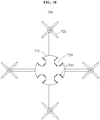
- a plurality of through-holes 130 is formed in the main body 110 of the drone 100.
- the extension member 220 may be provided in a number corresponding to the number of the through holes 130 in the landing stand 200.
- an eddy current may be generated between the through-holes 130 and the extension members 220, and thus a greater magnetic braking effect may be generated, compared to a case in which a single through-hole and a single extension member are provided.
- the plurality of drones 100 may safely land on the landing stand 200.
- the drone takeoff and landing system 10 may mount the cover 230 on the landing stand 200, and use it as a means to safely keep and transport the drones 100 stacked.
- a drone takeoff and landing system includes a drone (300, 500) including a through-hole (330, 530), and a landing stand (400, 600) including an extension member (420, 620) configured to pass through the through-hole (330, 530).
- a first electromagnet (340, 540) is disposed in the through-hole (330, 530), and a second electromagnet (440, 640) is disposed in the extension member (420, 620).
- a magnetic field of the first electromagnet (340, 540) and the second electromagnet (440, 640) is controlled in order to control a takeoff or landing speed of the drone (300, 500) or wirelessly charge the drone (300, 500).
- an electromagnet may be, for example, a solenoid formed by winding a coil on a cylindrical iron core. When a current passes through the coil wound in a cylindrical shape, a magnetic field may be formed. In addition, when the iron core is inserted therein, a stronger magnetic field may be obtained.
- an electromagnet that may be devised by those skilled in art may also be used.
- the drone 300 includes a main body 310 and a thruster 320 provided outside the main body 310.
- the through-hole 330 configured to pass through the main body 310 from top to bottom is formed in a portion of the main body 310.
- the first electromagnet 340 is disposed on a surface of the through-hole 330 of the drone 300 to form a radial magnetic field in a direction A vertical to a length direction of the through-hole 330.
- the landing stand 400 includes a landing pad 410 and the extension member 420 provided on one surface of the landing pad 410 and having a column shape.
- the second electromagnet 440 is disposed on a surface of the extension member 420 of the landing stand 400 to form a radial magnetic field in a direction A' vertical to a length direction of the extension member 420.
- the drone takeoff and landing system including the drone 300 and the landing stand 400 as described above may drive electromagnets to control a takeoff or landing speed of the drone 300.
- the first electromagnet 340 and the second electromagnet 440 may be controlled to have a same polarity, and thus a repulsive force may be generated between the first electromagnet 340 and the second electromagnet 440.
- the first electromagnet 340 and the second electromagnet 440 may be controlled to have a same polarity, and thus a repulsive force may be generated between the first electromagnet 340 and the second electromagnet 440.
- a repulsive force may be generated between the first electromagnet 340 and the second electromagnet 440.
- the drone 500 includes a main body 510 and a thruster 520 provided outside the main body 510, and a through-hole 530 configured to pass through the main body 510 from top to bottom is formed in a portion of the main body 510.
- the first electromagnet 540 is disposed on the surface of the through-hole 530 of the drone 500 to form an axial magnetic field in a direction B horizontal to a length direction of the through-hole 530.
- the landing stand 600 includes a landing pad 610 and an extension member 620 provided on one surface of the landing pad 610 and having a column shape.
- the second electromagnet 640 is disposed on the surface of the extension member 620 of the landing stand 600 to form an axial magnetic field in a direction B' vertical to a length direction of the extension member 620.
- the drone takeoff and landing system including the drone 500 and the landing stand 600 as described above may drive electromagnets while the drone 500 is resting on the landing stand 600 after being docked thereon, and thus generate magnetic induction between the first electromagnet 540 and the second electromagnet 640 to wirelessly charge the drone 500 by the magnetic induction.
- the drone takeoff and landing system may drive the electromagnets to control a takeoff or landing speed of the drone 500 as described above.
- the drone takeoff and landing system as described above may generate an eddy current when a drone lands on a landing stand, thereby preventing a collision between a plurality of drones, and further preventing a collision between the drones even when power of a drone is blocked, without being affected by such blockage.
- the drone takeoff and landing system may accommodate a plurality of drones, and facilitate takeoff, landing, and transportation of the drones.
- the drone takeoff and landing system may adjust a takeoff or landing speed of a drone, and thus enable the drone to take off fast from a landing stand and softly land on the landing stand, and also enable the drone to be wirelessly charged while the drone is resting on the landing stand.
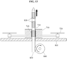
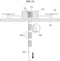
- a drone takeoff and landing system includes a drone 700 including a through-hole 730, and a landing stand 800 including a landing pad 810 and an extension member 820 provided on one surface of the landing pad 810 and configured to pass through the through-hole 730 of the drone 700.
- a landing stand 800 including a landing pad 810 and an extension member 820 provided on one surface of the landing pad 810 and configured to pass through the through-hole 730 of the drone 700.
- an eddy current or a magnetic field may be generated between the through-hole 730 and the extension member 820 to control a speed of the drone 700 or wirelessly charge the drone 700.
- the drone 700 includes a main body 710, and a thruster 720 provided outside the main body 710.
- the through-hole 730 is formed on a side surface of the main body 710 of the drone 700 such that one surface of the through-hole 730 is opened in a direction towards an outside of the main body 710.
- the through-hole 730 may be formed in a cylindrical shape.
- a shape of the through-hole 730 is not limited to the cylindrical shape, but a polygonal column shape such as a triangular prism shape and a rectangular column shape may also be applied as needed.
- one or more through-holes may be formed as the through-hole 730 in the drone 700.
- a magnetic body 740 is disposed in the through-hole 730 of the drone 700.
- the magnetic body 740 is provided on a surface of the through-hole 730.
- one or more magnetic bodies 740 are disposed, separately from each other at regular intervals, on the surface of the through -hole 730.
- the magnetic body 740 may also be formed to surround the entire surface of the through-hole 730.
- a magnetic body may be replaced with an electromagnet.
- the landing stand 800 includes a landing pad 810, and an extension member 820 provided on one surface of the landing pad 810 and having a column shape.
- the extension member 820 may be formed in a cylindrical shape, and formed also in a polygonal column shape such as a triangular prism shape and a rectangular column shape as needed.
- a nonferrous conductor is disposed in the extension member 820.
- the extension member 820 itself is formed as the nonferrous conductor.
- a plurality of nonferrous conductor elements 830 are additionally disposed on a surface of the extension member 820.
- the nonferrous conductor copper, lead, zinc, gold, platinum, mercury, silver, and the like may be used.
- the extension member 820 is provided in a number corresponding to the number of through-holes 730 formed in the drone 700.
- the extension member 820 of the landing stand 800 moves vertically with respect to the landing pad 810.
- the extension member 820 moves upwards.
- the extension member 820 moves downwards.
- the extension member 820 moves upwards from the landing pad 810 by a control member 840 provided below the landing pad 810.
- a control member 840 provided below the landing pad 810.
- an eddy current may be generated between the through-hole 730 and the extension member 820 to enable magnetic braking or wireless charging of the drone 700.
- the eddy current may be generated between the magnetic body 740 disposed in the through-hole 730 of the drone 700 and the nonferrous conductor disposed in the extension member 820 of the landing stand 800.
- the eddy current refers to a current, such as an alternating current, which is generated by electromagnetic induction of a conductor in a magnetic field that changes with time.
- a force generated by the eddy current may be used to generate a magnetic braking effect.
- the magnetic braking effect may be generated by the eddy current, thereby decreasing a landing speed of the drone 700 when it lands although it is in a non-powered state.
- the drone 700 when the drone 700 is resting on the landing stand 800, the drone 700 may be charged wirelessly.
- the extension member 820 moves downwards from the landing pad 810 by the control member 840 provided below the landing pad 810.
- the control member 840 provided below the landing pad 810.
- a nonferrous conductor is disposed on the surface of the through-hole 730 of the drone 700, and a magnetic body or an electromagnet is disposed on the extension member 820 of the landing stand 800.
- an eddy current may be generated between the nonferrous conductor disposed in the through-hole 730 of the drone 700 and the magnetic body or the electromagnet disposed in the extension member 820 of the landing stand 800.
- a force generated by the eddy current may generate a magnetic braking effect or be used to wirelessly charge the drone 700.
- a first electromagnet is disposed in the through-hole 730 of the drone 700
- a second electromagnet is disposed in the extension member 820, and a magnetic field of the first electromagnet and the second electromagnet may be controlled to control a takeoff or landing speed of the drone 700 or wirelessly charge the drone 700.
- an electromagnet may be, for example, a solenoid formed by winding a coil on a cylindrical iron core. When a current passes through the coil wound in a cylindrical shape, a magnetic field may be formed. In addition, when the iron core is inserted therein, a stronger magnetic field may be obtained.
- an electromagnet that is devised by those skilled in art may also be used.
- a polarity of the first electromagnet and the second electromagnet may be controlled to generate an attractive force or a repulsive force between the first electromagnet and the second electromagnet.
- a polarity of the first electromagnet and the second electromagnet may be controlled to generate an attractive force or a repulsive force between the first electromagnet and the second electromagnet.
- a drone takeoff and landing system includes a landing module 900 attachable to and detachable from the drone 700 and including a through-hole 911, and a landing stand including a landing pad and an extension member provided on one surface of the landing pad and configured to pass through the through-hole 911 of the landing module 900.
- the landing module 900 includes a pass-through member 910 in which the through-hole 911 is formed, and a magnetic body 930 disposed in the through-hole 911.
- a magnetic body may be replaced with an electromagnet.
- the landing module 900 may be directly attachable to or detachable from a portion of the main body 710 of the drone 700 which is an existing drone without a through-hole.
- the landing module 900 is attachable directly to a side surface of the main body 710 of the drone 700.
- a connecting loop or a screw tightener may be used to connect the landing module 900 and the main body 710.
- the landing module 900 includes a plurality of pass-through members 910, and a connection member 920 configured to connect the pass-through members 910 and attachable to and detachable from the drone 700.
- connection member 920 is formed of an elastic material, and thus a length thereof may be adjustable.
- the length of the connection member 920 may increase to be greater than a width of the main body 710, and then decrease again when the pass-through member 910 is disposed on the side surface of the main body 710.
- FIGS. 16b and 17b it is possible to stably fix the pass-through member 910 to the side surface of the main body 710.
- the length of the connection member 920 may also be adjustable through screw tightening. That is, the length of the connection member 920 may be fundamentally set to be longer than the width of the main body 710, and then be reduced through screw tightening when the pass-through member 910 is disposed on the side surface of the main body 710. Thus, as illustrated in FIGS. 16b and 17b , it is possible to stably fix the pass-through member 910 to the side surface of the main body 710.
- an eddy current may be generated between the magnetic body 930 disposed in the through-hole 911 of the landing module 900 and a nonferrous conductor disposed in the extension member of the landing pad when the extension member of the landing pad passes through the through-hole 911 of the landing module 900, and thus magnetic braking or wireless charging may occur in the drone 700.
- a nonferrous conductor is disposed in the through-hole 911 of the landing module 900, and a magnetic body or an electromagnet is disposed in the extension member of the landing stand.
- a first electromagnet is disposed in the through-hole 911 of the landing module 900
- a second electromagnet is disposed in the extension member of the landing pad.
- a drone takeoff and landing system may generate an eddy current or a magnetic field between a drone and a landing stand and adjust a takeoff or landing speed of the drone, and thus enable the drone to make a fast takeoff from the landing stand and a soft landing on the landing stand.
- a drone takeoff and landing system may generate an eddy current or a magnetic field between a drone and a landing stand, and thus enable the drone to be wirelessly charged when the drone rests on the landing stand.
- a drone takeoff and landing system may include a landing module attachable to or detachable from an existing drone, and a landing stand, and thus generate same effects described above for the existing drone of which a main body does not include a through-hole.
Abstract
Description
- Example embodiments relate to a drone takeoff and landing system.
- A drone refers to an unmanned aerial vehicle or a helicopter-shaped flying vehicle that flies or steers through induction of radio waves without a human pilot or operator, and is initially used for military purposes. A drone is currently used for commercial purposes, in addition to the military purposes. Thus, research has been actively conducted on drones to be used for such various purposes.
- As a demand for drones grows, a need for a landing gear capable of accommodating and transporting a plurality of drones at once is thus increasing. However, due to a shortage of a space accommodating the drones, a probability of a collision among the drones is also increasing.
- Thus, there is a desire for a system that may prevent such a collision among the drones, and accommodate and transport the drones safely.
- For example, the
US Patent Publication No. 2012-0061508 entitled "Device for Firing Weapons from an Armed Drone" published in March 15, 2012, discloses a drone. - An aspect provides a drone takeoff and landing system that may prevent a collision between drones when the drones land on a landing stand, and prevent a collision between drones without being affected when power of a drone is blocked.
- An aspect also provides a drone takeoff and landing system that may accommodate a plurality of drones and facilitate takeoff, landing, and transportation of the drones.
- An aspect also provides a drone takeoff and landing system that may adjust a takeoff or landing speed of a drone, thereby enabling the drone to take off fast from a landing stand and land softly on the landing stand, and also enabling the drone to be wirelessly charged while the drone is resting on the landing stand.
- An aspect also provides a drone takeoff and landing system that may generate an eddy current or a magnetic field between a drone and a landing stand and adjust a takeoff or landing speed of the drone, thereby enabling the drone to take off fast from the landing stand and land softly on the landing stand.
- An aspect also provides a drone takeoff and landing system that may generate an eddy current or a magnetic field between a drone and a landing stand, thereby enabling the drone to be wirelessly charged while the drone is resting on the landing stand.
- An aspect also provides a drone takeoff and landing system that may include a landing module attachable to or detachable from an existing drone and a landing stand, thereby achieving same effects as described above from the existing drone without a through-hole in a main body of the existing drone.
- According to an example embodiment, there is provided a drone takeoff and landing system including a drone including a through-hole, and a landing stand including an extension member configured to pass through the through-hole. When the extension member of the landing stand passes through the through-hole of the drone, an eddy current may be generated between the through-hole and the extension member, and magnetic braking may occur in the drone.
- A magnetic body may be disposed on a surface of the through-hole, and the extension member may be formed as a nonferrous conductor or include a nonferrous conductor element provided on a surface of the extension member. The eddy current may be generated between the magnetic body and the nonferrous conductor.
- A nonferrous conductor element may be disposed on the surface of the through-hole, and a magnetic body may be disposed on the surface of the extension member. The eddy current may be generated between the magnetic body and the nonferrous conductor element.
- The drone may include a main body including the through-hole, and a thruster provided outside the main body. The landing stand may include a landing pad, on one surface of which the extension member having a column shape is provided.
- The drone takeoff and landing system may include a plurality of drones. A length of the extension member may be set to be greater than a total height of the drones. The extension member may pass through respective through-holes of the drones, and the drones may be stacked in sequential order on the landing stand.
- The landing stand may further include a cover provided on the landing pad to protect the drones stacked on the landing stand.
- The through-hole may be formed as a plurality of through-holes. The extension member may be provided in a number corresponding to the number of the through-holes.
- The drone takeoff and landing system may include the drone including the through-hole, and the landing stand including the extension member configured to pass through the through-hole. A first electromagnet may be disposed in the through-hole, and a second electromagnet may be disposed in the extension member. A magnetic field of the first electromagnet and the second electromagnet may be controlled to control a takeoff or landing speed of the drone or wirelessly charge the drone.
- Each of the first electromagnet and the second electromagnet may be disposed to form a radial magnetic field in a direction vertical to a length direction of the through-hole and the extension member, respectively. A polarity of the first electromagnet and the second electromagnet may be controlled to increase the takeoff speed of the drone when the drone takes off from the landing stand, or to decrease the landing speed of the drone when the drone lands on the landing stand. The drone may be wirelessly charged by magnetic induction between the first electromagnet and the second electromagnet.
- Each of the first electromagnet and the second electromagnet may be disposed to form an axial magnetic field in a direction horizontal to the length direction of the through-hole and the extension member, respectively. The polarity of the first electromagnet and the second electromagnet may be controlled to increase the takeoff speed of the drone when the drone takes off from the landing stand, or to decrease the landing speed of the drone when the drone lands on the landing stand. The drone may be wirelessly charged by magnetic induction between the first electromagnet and the second electromagnet.
- According to a modified example embodiment, there is provided a drone takeoff and landing system including a drone including a through-hole, and a landing stand including a landing pad and an extension member provided on one surface of the landing pad and configured to pass through the through-hole. The through-hole may be formed on a side surface of a main body of the drone such that one surface of the through-hole is opened in a direction towards an outside of the main body. The extension member of the landing stand may be configured to move vertically from the landing pad, and configured to move selectively upwards or downwards when the drone takes off or lands.
- The through-hole may be formed as a plurality of through-holes, and the extension member may be provided in a number corresponding to the number of the through-holes.
- When the extension member may pass through the through-hole of the drone, an eddy current may be generated between the through-hole and the extension member, and magnetic braking or wireless charging may occur in the drone.
- A magnetic body or an electromagnet may be disposed in the through-hole, and a nonferrous conductor may be disposed in the extension member. The eddy current may be generated between the magnetic body or the electromagnet, and the nonferrous conductor.
- A nonferrous conductor may be disposed in the through-hole, and a magnetic body or an electromagnet may be disposed in the extension member. The eddy current may be generated between the magnetic body or the electromagnet, and the nonferrous conductor.
- A first electromagnet may be disposed in the through-hole, and a second electromagnet may be disposed in the extension member. A magnetic field of the first electromagnet and the second electromagnet may be controlled to control a takeoff or landing speed of the drone or wirelessly charge the drone.
- According to another example embodiment, there is provided a drone takeoff and landing system including a landing module attachable to or detachable from a drone and including a through-hole, and a landing stand including a landing pad and an extension member provided on one surface of the landing pad and configured to pass through the through-hole.
- The landing module may include a plurality of pass-through members each including a through-hole, and a connection member configured to connect the pass-through members and attachable to and detachable from the drone.
- In a case in which the landing module is attached to the drone, an eddy current or a magnetic field may be generated between the through-hole and the extension member when the extension member passes through the through-hole, to control a speed of the drone or wirelessly charge the drone.
- The connection member may be formed of an elastic material such that a length thereof is adjustable, or a length of the connection member may be adjustable through screw tightening.
- A magnetic body or an electromagnet may be disposed in one of the through-hole and the extension member, and a nonferrous conductor may be disposed in the other. The eddy current may be generated between the magnetic body or the electromagnet, and the nonferrous conductor, and magnetic braking or wireless charging may occur in the drone.
- A first electromagnet may be disposed in the through-hole, and a second electromagnet may be disposed in the extension member. A magnetic field of the first electromagnet and the second electromagnet may be controlled to control a takeoff or landing speed of the drone or wirelessly charge the drone.
- According to an example embodiment described herein, a drone takeoff and landing system may prevent a collision between drones when the drones land on a landing stand, and prevent a collision between drones without being affected when power of a drone is blocked.
- The drone takeoff and landing system may accommodate a plurality of drones, and facilitate takeoff, landing, and transportation of the drones.
- The drone takeoff and landing system may adjust a takeoff or landing speed of a drone, and thus enable the drone to take off fast from a landing stand and land softly on the landing stand, and also enable the drone to be wirelessly charged while the drone is resting on the landing stand.
- In an example, the drone takeoff and landing system may generate an eddy current or a magnetic field between a drone and a landing stand and adjust a takeoff or landing speed of the drone, and thus may enable the drone to take off fast from the landing stand and land softly on the landing stand.
- In another example, the drone takeoff and landing system may generate an eddy current or a magnetic field between a drone and a landing stand, and thus enable the drone to be wirelessly charged while the drone is resting on the landing stand.
- According to another example embodiment described herein, a drone takeoff and landing system may include a landing module attachable to or detachable from an existing drone and a landing stand, thereby achieving same effects as described above from the existing drone without a through-hole in a main body of the existing drone.
-
-
FIGS. 1a and 1b illustrate a drone according to an example embodiment. -
FIGS. 2a and 2b illustrate a landing stand according to an example embodiment. -
FIG. 3 illustrates a drone takeoff and landing system according to an example embodiment. -
FIGS. 4 and5 illustrate a drone takeoff and landing system including a plurality of through-holes and a plurality of extension members according to an example embodiment. -
FIGS. 6a and 6b illustrate a drone forming a radial magnetic field according to an example embodiment. -
FIG. 7 illustrates a landing stand forming a radial magnetic field according to an example embodiment. -
FIGS. 8a and 8b illustrate a drone forming an axial magnetic field according to an example embodiment. -
FIG. 9 illustrates a landing stand forming an axial magnetic field according to an example embodiment. -
FIGS. 10 and11 illustrate a drone according a modified example embodiment. -
FIG. 12 illustrates a landing stand according a modified example embodiment. -
FIGS. 13 and14 illustrate a drone takeoff and landing system according a modified example embodiment. -
FIGS. 15a through 17b illustrate a landing module of a drone takeoff and landing system, and a drone to which the landing module is attached according to another example embodiment. - Hereinafter, some example embodiments will be described in detail with reference to the accompanying drawings. The example embodiments are described in the following detailed description. Regarding the reference numerals assigned to the elements in the drawings, it should be noted that the same elements will be designated by the same reference numerals, wherever possible, even though they are shown in different drawings.
- Also, in the description of the example embodiments, detailed description of well-known related structures or functions will be omitted when it is deemed that such description will cause ambiguous interpretation of the present disclosure.
- The terms used herein are not to be interpreted based solely on the terms themselves, but to be interpreted based on the meanings of the terms as defined herein and the overall context of the present disclosure. In addition, the terms may need to be construed as corresponding to technical features or inventive concept described in the first example embodiment based on what an inventor(s) defines each of the terms.
- Thus, the terms used herein should be construed as corresponding to technical features or inventive concept of a drone takeoff and landing system according to an example embodiment.
- It should be understood that there is no intent to limit the present disclosure to a particular example embodiment disclosed. The examples and illustrated configurations are provided merely as a desirable example of a drone takeoff and landing system according to an example embodiment, and not represent all the technical features or inventive concept of the drone takeoff and landing system. Thus, various changes, modifications, and equivalents of the methods, apparatuses, and/or systems described herein will be apparent after an understanding of the present disclosure.
-
FIGS. 1a and 1b illustrate a drone according to an example embodiment.FIGS. 2a and 2b illustrate a landing stand according to an example embodiment.FIG. 3 illustrates a drone takeoff and landing system according to an example embodiment.FIGS. 4 and5 illustrate a drone takeoff and landing system including a plurality of through-holes and a plurality of extension members according to an example embodiment.FIGS. 6a and 6b illustrate a drone forming a radial magnetic field according to an example embodiment.FIG. 7 illustrates a landing stand forming a radial magnetic field according to an example embodiment.FIGS. 8a and 8b illustrate a drone forming an axial magnetic field according to an example embodiment.FIG. 9 illustrates a landing stand forming an axial magnetic field according to an example embodiment.FIGS. 10 and11 illustrate a drone according a modified example embodiment.FIG. 12 illustrates a landing stand according a modified example embodiment.FIGS. 13 and14 illustrate a drone takeoff and landing system according a modified example embodiment.FIGS. 15a through 17b illustrate a landing module of a drone takeoff and landing system, and a drone to which the landing module is attached according to another example embodiment. - Referring to
FIGS. 1a through 3 , a drone takeoff andlanding system 10 includes adrone 100 including a through-hole 130, and alanding stand 200 including anextension member 220 configured to pass through the through-hole 130 of thedrone 100. When theextension member 220 of the landing stand 200 passes through the through-hole 130 of thedrone 100, an eddy current may be generated between the through-hole 130 and theextension member 220, and thus magnetic braking may occur in thedrone 100. - In detail, referring to
FIGS. 1a and 1b , thedrone 100 includes amain body 110, and athruster 120 provided outside themain body 110. The through-hole 130 is formed in a portion of themain body 110 and configured to pass through themain body 110 from top to bottom. The through-hole 130 may be formed in a cylindrical shape. However, a shape of the through-hole 130 is not limited to the cylindrical shape, but a polygonal column shape such as a triangular prism shape and a rectangular column shape may also be applied as needed. - In addition, a
magnetic body 140 is disposed on a surface of the through-hole 130 of thedrone 100. Here, one or moremagnetic bodies 140 may be disposed, separately from each other at regular intervals, on the surface of the through-hole 130. In addition, themagnetic body 140 may be formed to surround the entire surface of the through-hole 130. - Referring to
FIGS. 2a and 2b , thelanding stand 200 includes alanding pad 210, and theextension member 220 provided on one surface of thelanding pad 210 and formed in a column shape. Theextension member 220 may be formed in a cylindrical shape, and also in a polygonal column shape such as a triangular prism shape and a rectangular column shape as needed. Theextension member 220 may be formed as a nonferrous conductor. In addition, a plurality ofnonferrous conductor elements 240 may be additionally disposed on a surface of theextension member 220. As the nonferrous conductor, copper, lead, zinc, gold, platinum, mercury, silver, and the like may be used. - A cross-sectional area of the
landing pad 210 may be set to be greater than an entire cross-sectional area of thedrone 100 to be received by thelanding stand 200. The landing stand 200 further includes acover 230 provided on thelanding pad 210 and configured to protect thedrone 100 stacked on thelanding stand 200. In such a case, thecover 230 may be closely connected to thelanding pad 210 to seal or cover thedrone 100 as a whole. - In addition, the cross-sectional area of the
landing pad 210 may be set to be smaller than the entire cross-sectional area of thedrone 100 to be received by thelanding stand 200. In such a case, thecover 230 may be formed in an open type, and fixed to thelanding stand 200 by a fixing element provided at an end of theextension member 220. - Referring to
FIG. 3 , the drone takeoff andlanding system 10 includes a plurality ofdrones 100, and a length of theextension member 220 of thelanding stand 200 is set to be longer than a total height of thedrones 100. Thus, as theextension member 220 passes through through-holes 130 of thedrones 100, thedrones 100 may be sequentially stacked on thelanding stand 200. - Thus, while the through-
hole 130 of thedrone 100 is passing through theextension member 220 of thelanding stand 200, an eddy current may be generated between themagnetic body 140 disposed on the surface of the through-hole 130 of thedrone 100 and thenonferrous conductor elements 240 disposed on the surface of theextension member 220 of thelanding stand 200. The eddy current refers to a current, such as an alternating current, which is generated by electromagnetic induction of a conductor in a magnetic field that changes with time. A force generated by the eddy current may be used to generate a magnetic braking effect. - Thus, while the through-
hole 130 of thedrone 100 is passing through theextension member 220 of thelanding stand 200, the magnetic braking effect may be generated by the eddy current, thereby preventing a collision between thedrones 100 when they land. This may be maintained even when power of a drone is blocked. - In contrast to what has been described above, a nonferrous conductor element may be disposed on the surface of the through-
hole 130 of thedrone 100, and a magnetic body may be disposed on the surface of theextension member 220 of thelanding stand 200. In such a case, while the through-hole 130 of thedrone 100 is passing through theextension member 220 of thelanding stand 200, an eddy current may be generated between the nonferrous conductor element disposed on the surface of the through-hole 130 of thedrone 100 and the magnetic body disposed on the surface of theextension member 220 of thelanding stand 200, and a force generated by the eddy current may be used to generate a magnetic braking effect. - Referring to
FIGS. 4 and5 , a plurality of through-holes 130 is formed in themain body 110 of thedrone 100. Here, theextension member 220 may be provided in a number corresponding to the number of the throughholes 130 in thelanding stand 200. In such case, an eddy current may be generated between the through-holes 130 and theextension members 220, and thus a greater magnetic braking effect may be generated, compared to a case in which a single through-hole and a single extension member are provided. - In the drone takeoff and
landing system 10 including such components described above, the plurality ofdrones 100 may safely land on thelanding stand 200. In addition, when thedrones 100 are stacked on thelanding stand 200, the drone takeoff andlanding system 10 may mount thecover 230 on thelanding stand 200, and use it as a means to safely keep and transport thedrones 100 stacked. - Referring to
FIGS. 6a through 9 , a drone takeoff and landing system according to an example embodiment includes a drone (300, 500) including a through-hole (330, 530), and a landing stand (400, 600) including an extension member (420, 620) configured to pass through the through-hole (330, 530). A first electromagnet (340, 540) is disposed in the through-hole (330, 530), and a second electromagnet (440, 640) is disposed in the extension member (420, 620). Here, a magnetic field of the first electromagnet (340, 540) and the second electromagnet (440, 640) is controlled in order to control a takeoff or landing speed of the drone (300, 500) or wirelessly charge the drone (300, 500). Here, an electromagnet may be, for example, a solenoid formed by winding a coil on a cylindrical iron core. When a current passes through the coil wound in a cylindrical shape, a magnetic field may be formed. In addition, when the iron core is inserted therein, a stronger magnetic field may be obtained. However, examples are not limited to the foregoing, and an electromagnet that may be devised by those skilled in art may also be used. - In detail, referring to
FIGS. 6a and 6b , thedrone 300 includes amain body 310 and athruster 320 provided outside themain body 310. The through-hole 330 configured to pass through themain body 310 from top to bottom is formed in a portion of themain body 310. In addition, thefirst electromagnet 340 is disposed on a surface of the through-hole 330 of thedrone 300 to form a radial magnetic field in a direction A vertical to a length direction of the through-hole 330. - In addition, referring to
FIG. 7 , thelanding stand 400 includes alanding pad 410 and theextension member 420 provided on one surface of thelanding pad 410 and having a column shape. Thesecond electromagnet 440 is disposed on a surface of theextension member 420 of the landing stand 400 to form a radial magnetic field in a direction A' vertical to a length direction of theextension member 420. - The drone takeoff and landing system including the
drone 300 and thelanding stand 400 as described above may drive electromagnets to control a takeoff or landing speed of thedrone 300. - That is, while the through-
hole 330 of thedrone 300 is passing through theextension member 420 of thelanding stand 400 for thedrone 300 to make a landing on thelanding stand 400, thefirst electromagnet 340 and thesecond electromagnet 440 may be controlled to have a same polarity, and thus a repulsive force may be generated between thefirst electromagnet 340 and thesecond electromagnet 440. Thus, it is possible to decrease the landing speed of thedrone 300 when thedrone 300 lands on thelanding stand 400. - In addition, using the same principle, when the
drone 300 is taking off from thelanding stand 400, thefirst electromagnet 340 and thesecond electromagnet 440 may be controlled to have a same polarity, and thus a repulsive force may be generated between thefirst electromagnet 340 and thesecond electromagnet 440. Thus, it is possible to increase the takeoff speed of thedrone 300. - In addition, it is possible to wirelessly charge the
drone 300 by magnetic induction between thefirst electromagnet 340 and thesecond electromagnet 440. - Referring to
FIGS. 8a and 8b , thedrone 500 includes amain body 510 and athruster 520 provided outside themain body 510, and a through-hole 530 configured to pass through themain body 510 from top to bottom is formed in a portion of themain body 510. In addition, thefirst electromagnet 540 is disposed on the surface of the through-hole 530 of thedrone 500 to form an axial magnetic field in a direction B horizontal to a length direction of the through-hole 530. - In addition, referring to
FIG. 9 , thelanding stand 600 includes alanding pad 610 and anextension member 620 provided on one surface of thelanding pad 610 and having a column shape. Thesecond electromagnet 640 is disposed on the surface of theextension member 620 of the landing stand 600 to form an axial magnetic field in a direction B' vertical to a length direction of theextension member 620. - The drone takeoff and landing system including the
drone 500 and thelanding stand 600 as described above may drive electromagnets while thedrone 500 is resting on thelanding stand 600 after being docked thereon, and thus generate magnetic induction between thefirst electromagnet 540 and thesecond electromagnet 640 to wirelessly charge thedrone 500 by the magnetic induction. In addition, the drone takeoff and landing system may drive the electromagnets to control a takeoff or landing speed of thedrone 500 as described above. - The drone takeoff and landing system as described above may generate an eddy current when a drone lands on a landing stand, thereby preventing a collision between a plurality of drones, and further preventing a collision between the drones even when power of a drone is blocked, without being affected by such blockage.
- In addition, the drone takeoff and landing system may accommodate a plurality of drones, and facilitate takeoff, landing, and transportation of the drones.
- In addition, the drone takeoff and landing system may adjust a takeoff or landing speed of a drone, and thus enable the drone to take off fast from a landing stand and softly land on the landing stand, and also enable the drone to be wirelessly charged while the drone is resting on the landing stand.
- Referring to
FIGS. 10 through 12 , according to a modified example embodiment, a drone takeoff and landing system includes adrone 700 including a through-hole 730, and alanding stand 800 including alanding pad 810 and anextension member 820 provided on one surface of thelanding pad 810 and configured to pass through the through-hole 730 of thedrone 700. When theextension member 820 of the landing stand 800 passes through the through-hole 730 of thedrone 700, an eddy current or a magnetic field may be generated between the through-hole 730 and theextension member 820 to control a speed of thedrone 700 or wirelessly charge thedrone 700. - In detail, referring to
FIGS. 10 and11 , thedrone 700 includes amain body 710, and athruster 720 provided outside themain body 710. In addition, the through-hole 730 is formed on a side surface of themain body 710 of thedrone 700 such that one surface of the through-hole 730 is opened in a direction towards an outside of themain body 710. Here, the through-hole 730 may be formed in a cylindrical shape. However, a shape of the through-hole 730 is not limited to the cylindrical shape, but a polygonal column shape such as a triangular prism shape and a rectangular column shape may also be applied as needed. Here, one or more through-holes may be formed as the through-hole 730 in thedrone 700. - A
magnetic body 740 is disposed in the through-hole 730 of thedrone 700. For example, themagnetic body 740 is provided on a surface of the through-hole 730. In this example, one or moremagnetic bodies 740 are disposed, separately from each other at regular intervals, on the surface of the through -hole 730. In addition, themagnetic body 740 may also be formed to surround the entire surface of the through-hole 730. Here, a magnetic body may be replaced with an electromagnet. - Referring to
FIG. 12 , thelanding stand 800 includes alanding pad 810, and anextension member 820 provided on one surface of thelanding pad 810 and having a column shape. Here, theextension member 820 may be formed in a cylindrical shape, and formed also in a polygonal column shape such as a triangular prism shape and a rectangular column shape as needed. A nonferrous conductor is disposed in theextension member 820. For example, theextension member 820 itself is formed as the nonferrous conductor. A plurality ofnonferrous conductor elements 830 are additionally disposed on a surface of theextension member 820. As the nonferrous conductor, copper, lead, zinc, gold, platinum, mercury, silver, and the like may be used. Here, theextension member 820 is provided in a number corresponding to the number of through-holes 730 formed in thedrone 700. - Referring to
FIGS. 13 and14 , theextension member 820 of thelanding stand 800 moves vertically with respect to thelanding pad 810. When thedrone 700 lands, theextension member 820 moves upwards. When thedrone 700 takes off, theextension member 820 moves downwards. - In detail, referring to
FIG. 13 , when thedrone 700 is to land on thelanding stand 800, theextension member 820 moves upwards from thelanding pad 810 by acontrol member 840 provided below thelanding pad 810. Thus, when theextension member 820 passes through the through-hole 730 of thedrone 700, an eddy current may be generated between the through-hole 730 and theextension member 820 to enable magnetic braking or wireless charging of thedrone 700. - That is, while through-
hole 730 of thedrone 700 is passing through theextension member 820 of thelanding stand 800, the eddy current may be generated between themagnetic body 740 disposed in the through-hole 730 of thedrone 700 and the nonferrous conductor disposed in theextension member 820 of thelanding stand 800. Here, the eddy current refers to a current, such as an alternating current, which is generated by electromagnetic induction of a conductor in a magnetic field that changes with time. A force generated by the eddy current may be used to generate a magnetic braking effect. - Thus, while the through-
hole 730 of thedrone 700 is passing through theextension member 820 of thelanding stand 800, the magnetic braking effect may be generated by the eddy current, thereby decreasing a landing speed of thedrone 700 when it lands although it is in a non-powered state. - In addition, when the
drone 700 is resting on thelanding stand 800, thedrone 700 may be charged wirelessly. - Referring to
FIG. 14 , when thedrone 700 is to take off from thelanding stand 800, theextension member 820 moves downwards from thelanding pad 810 by thecontrol member 840 provided below thelanding pad 810. Thus, when thedrone 700 takes off, it is possible to eliminate a decrease in takeoff speed by the eddy current generated between the through-hole 730 and theextension member 820. Thus, through such an operation, when a drone does not take off or land, or the drone is not wirelessly charged, it is possible to safely keep theextension member 820 from an external environment by disposing theextension member 820 below thelanding pad 810. - In contrast to what has been described above, a nonferrous conductor is disposed on the surface of the through-
hole 730 of thedrone 700, and a magnetic body or an electromagnet is disposed on theextension member 820 of thelanding stand 800. In such a case, while the through-hole 730 of thedrone 700 is passing through theextension member 820 of thelanding stand 800, an eddy current may be generated between the nonferrous conductor disposed in the through-hole 730 of thedrone 700 and the magnetic body or the electromagnet disposed in theextension member 820 of thelanding stand 800. Here, a force generated by the eddy current may generate a magnetic braking effect or be used to wirelessly charge thedrone 700. - In addition, a first electromagnet is disposed in the through-
hole 730 of thedrone 700, and a second electromagnet is disposed in theextension member 820, and a magnetic field of the first electromagnet and the second electromagnet may be controlled to control a takeoff or landing speed of thedrone 700 or wirelessly charge thedrone 700. - Here, an electromagnet may be, for example, a solenoid formed by winding a coil on a cylindrical iron core. When a current passes through the coil wound in a cylindrical shape, a magnetic field may be formed. In addition, when the iron core is inserted therein, a stronger magnetic field may be obtained. However, examples are not limited to the foregoing, an electromagnet that is devised by those skilled in art may also be used.
- As described above, it is possible to adjust a takeoff or landing speed of the
drone 700 by driving the electromagnets. - That is, while the through-
hole 730 of thedrone 700 is passing through theextension member 820 of thelanding stand 800 for thedrone 700 to land on thelanding stand 800, a polarity of the first electromagnet and the second electromagnet may be controlled to generate an attractive force or a repulsive force between the first electromagnet and the second electromagnet. Thus, when thedrone 700 lands on thelanding stand 800, it is possible to decrease the landing speed of thedrone 700. - In addition, using the same principle, when the
drone 700 is taking off from thelanding stand 800, a polarity of the first electromagnet and the second electromagnet may be controlled to generate an attractive force or a repulsive force between the first electromagnet and the second electromagnet. Thus, it is possible to increase the takeoff speed of thedrone 700. - In addition, it is possible to wirelessly charge the
drone 700 by magnetic induction between the first electromagnet and the second electromagnet. - Referring to
FIGS. 15a through 17b , a drone takeoff and landing system according to another example embodiment includes alanding module 900 attachable to and detachable from thedrone 700 and including a through-hole 911, and a landing stand including a landing pad and an extension member provided on one surface of the landing pad and configured to pass through the through-hole 911 of thelanding module 900. - In detail, as illustrated
FIG. 15a , thelanding module 900 includes a pass-throughmember 910 in which the through-hole 911 is formed, and amagnetic body 930 disposed in the through-hole 911. Here, a magnetic body may be replaced with an electromagnet. - As illustrated in
FIG. 15b , thelanding module 900 may be directly attachable to or detachable from a portion of themain body 710 of thedrone 700 which is an existing drone without a through-hole. For example, thelanding module 900 is attachable directly to a side surface of themain body 710 of thedrone 700. In this example, a connecting loop or a screw tightener may be used to connect thelanding module 900 and themain body 710. - In addition, as illustrated in
FIGS. 16a and17a , thelanding module 900 includes a plurality of pass-throughmembers 910, and aconnection member 920 configured to connect the pass-throughmembers 910 and attachable to and detachable from thedrone 700. - The
connection member 920 is formed of an elastic material, and thus a length thereof may be adjustable. The length of theconnection member 920 may increase to be greater than a width of themain body 710, and then decrease again when the pass-throughmember 910 is disposed on the side surface of themain body 710. Thus, as illustrated inFIGS. 16b and17b , it is possible to stably fix the pass-throughmember 910 to the side surface of themain body 710. - The length of the
connection member 920 may also be adjustable through screw tightening. That is, the length of theconnection member 920 may be fundamentally set to be longer than the width of themain body 710, and then be reduced through screw tightening when the pass-throughmember 910 is disposed on the side surface of themain body 710. Thus, as illustrated inFIGS. 16b and17b , it is possible to stably fix the pass-throughmember 910 to the side surface of themain body 710. - Thus, in a case in which the
landing module 900 is attached to thedrone 700, an eddy current may be generated between themagnetic body 930 disposed in the through-hole 911 of thelanding module 900 and a nonferrous conductor disposed in the extension member of the landing pad when the extension member of the landing pad passes through the through-hole 911 of thelanding module 900, and thus magnetic braking or wireless charging may occur in thedrone 700. - In contrast to what has been described above, a nonferrous conductor is disposed in the through-
hole 911 of thelanding module 900, and a magnetic body or an electromagnet is disposed in the extension member of the landing stand. - In addition, a first electromagnet is disposed in the through-
hole 911 of thelanding module 900, and a second electromagnet is disposed in the extension member of the landing pad. Thus, in a case in which thelanding module 900 is attached to thedrone 700, a magnetic field may be generated between the first electromagnet of thelanding module 900 and the second electromagnet of the landing pad. Thus, by controlling the magnetic field, it is possible to control a takeoff or landing speed of thedrone 700, or wirelessly charge thedrone 700. - A drone takeoff and landing system according to a modified example embodiment as described above may generate an eddy current or a magnetic field between a drone and a landing stand and adjust a takeoff or landing speed of the drone, and thus enable the drone to make a fast takeoff from the landing stand and a soft landing on the landing stand.
- A drone takeoff and landing system according to a modified example embodiment as described above may generate an eddy current or a magnetic field between a drone and a landing stand, and thus enable the drone to be wirelessly charged when the drone rests on the landing stand.
- A drone takeoff and landing system according to another example embodiment as described above may include a landing module attachable to or detachable from an existing drone, and a landing stand, and thus generate same effects described above for the existing drone of which a main body does not include a through-hole.
- While this disclosure includes specific examples, it will be apparent to one of ordinary skill in the art that various changes in form and details may be made in these examples without departing from the spirit and scope of the claims and their equivalents. The examples described herein are to be considered in a descriptive sense only, and not for purposes of limitation. Descriptions of features or aspects in each example are to be considered as being applicable to similar features or aspects in other examples. Suitable results may be achieved if the described techniques are performed in a different order, and/or if components in a described system, architecture, device, or circuit are combined in a different manner and/or replaced or supplemented by other components or their equivalents. Therefore, the scope of the disclosure is defined not by the detailed description, but by the claims and their equivalents, and all variations within the scope of the claims and their equivalents are to be construed as being included in the disclosure.
Claims (20)
- A drone takeoff and landing system, comprising:a drone including a through-hole;a landing stand including an extension member configured to pass through the through-hole,
wherein, when the extension member of the landing stand passes through the through-hole of the drone, an eddy current is generated between the through-hole and the extension member, and magnetic braking occurs in the drone. - The drone takeoff and landing system of claim 1, wherein a magnetic body is disposed on a surface of the through-hole, and the extension member is formed as a nonferrous conductor or includes a nonferrous conductor element provided on a surface of the extension member,
wherein the eddy current is generated between the magnetic body and the nonferrous conductor. - The drone takeoff and landing system of claim 1, wherein a nonferrous conductor element is disposed on a surface of the through-hole, and a magnetic body is disposed on a surface of the extension member,
wherein the eddy current is generated between the magnetic body and the nonferrous conductor element. - The drone takeoff and landing system of claim 2 or 3, wherein the drone includes:a main body including the through-hole; anda thruster provided outside the main body;
wherein the landing stand includes a landing pad, on one surface of which the extension member having a column shape is provided. - The drone takeoff and landing system of claim 4, comprising:a plurality of drones,
wherein a length of the extension member is set to be greater than a total height of the drones, andthe extension member passes through respective through-holes of the drones, and the drones are stacked in sequential order on the landing stand. - The drone takeoff and landing system of claim 4, wherein the landing stand further includes:
a cover provided on the landing pad to protect drones stacked on the landing stand. - The drone takeoff and landing system of claim 1, wherein the through-hole is formed as a plurality of through-holes,
wherein the extension member is provided in a number corresponding to the number of the through-holes. - The drone takeoff and landing system of claim 1, wherein a first electromagnet is disposed in the through-hole, and a second electromagnet is disposed in the extension member,
wherein a magnetic field of the first electromagnet and the second electromagnet is controlled to control a takeoff or landing speed of the drone or wirelessly charge the drone. - The drone takeoff and landing system of claim 8, wherein each of the first electromagnet and the second electromagnet is disposed to form a radial magnetic field in a direction vertical to a length direction of the through-hole and the extension member, respectively,
wherein a polarity of the first electromagnet and the second electromagnet is controlled to increase the takeoff speed of the drone when the drone takes off from the landing stand, or to decrease the landing speed of the drone when the drone lands on the landing stand, and
the drone is wirelessly charged by magnetic induction between the first electromagnet and the second electromagnet. - The drone takeoff and landing system of claim 8, wherein each of the first electromagnet and the second electromagnet is disposed to form an axial magnetic field in a direction horizontal to a length direction of the through-hole and the extension member, respectively,
wherein a polarity of the first electromagnet and the second electromagnet is controlled to increase the takeoff speed of the drone when the drone takes off from the landing stand, or to decrease the landing speed of the drone when the drone lands on the landing stand, and
the drone is wirelessly charged by magnetic induction between the first electromagnet and the second electromagnet. - A drone takeoff and landing system, comprising:a drone including a through-hole; anda landing stand including a landing pad and an extension member provided on one surface of the landing pad and configured to pass through the through-hole,wherein the through-hole is formed on a side surface of a main body of the drone such that one surface of the through-hole is opened in a direction towards an outside of the main body,the extension member of the landing stand is configured to move vertically from the landing pad, and configured to move selectively upwards or downwards when the drone takes off or lands, andwhen the extension member passes through the through-hole of the drone, an eddy current is generated between the through-hole and the extension member, and magnetic braking or wireless charging occurs in the drone.
- The drone takeoff and landing system of claim 11, wherein the through-hole is formed as a plurality of through-holes, and
the extension member is provided as a plurality of extension members. - The drone takeoff and landing system of claim 11, wherein a magnetic body or an electromagnet is disposed in the through-hole, and
a nonferrous conductor is disposed in the extension member,
wherein the eddy current is generated between the magnetic body or the electromagnet, and the nonferrous conductor. - The drone takeoff and landing system of claim 11, wherein a nonferrous conductor is disposed in the through-hole, and
a magnetic body or an electromagnet is disposed in the extension member,
wherein the eddy current is generated between the magnetic body or the electromagnet, and the nonferrous conductor. - The drone takeoff and landing system of claim 11, wherein a first electromagnet is disposed in the through-hole, and a second electromagnet is disposed in the extension member,
wherein a magnetic field of the first electromagnet and the second electromagnet is controlled to control a takeoff or landing speed of the drone or wirelessly charge the drone. - A drone takeoff and landing system, comprising:a landing module attachable to or detachable from a drone and including a through-hole; anda landing stand including a landing pad and an extension member provided on one surface of the landing pad and configured to pass through the through-hole,
wherein, in a case in which the landing module is attached to the drone, an eddy current or a magnetic field is generated between the through-hole and the extension member when the extension member passes through the through-hole, to control a speed of the drone or wirelessly charge the drone. - The drone takeoff and landing system of claim 16, wherein the landing module includes:a plurality of pass-through members each including a through-hole; anda connection member configured to connect the pass-through members and attachable to and detachable from the drone.
- The drone takeoff and landing system of claim 17, wherein the connection member is formed of an elastic material such that a length thereof is adjustable, or a length of the connection member is adjustable through screw tightening.
- The drone takeoff and landing system of claim 16, wherein a magnetic body or an electromagnet is disposed in one of the through-hole and the extension member, and a nonferrous conductor is disposed in the other,
wherein the eddy current is generated between the magnetic body or the electromagnet, and the nonferrous conductor, and magnetic braking or wireless charging occurs in the drone. - The drone takeoff and landing system of claim 16, wherein a first electromagnet is disposed in the through-hole, and a second electromagnet is disposed in the extension member,
wherein a magnetic field of the first electromagnet and the second electromagnet is controlled to control a takeoff or landing speed of the drone or wirelessly charge the drone.
Applications Claiming Priority (2)
| Application Number | Priority Date | Filing Date | Title |
|---|---|---|---|
| KR1020160169429A KR101874204B1 (en) | 2016-12-13 | 2016-12-13 | Drone's landing system |
| PCT/KR2017/014115 WO2018110883A1 (en) | 2016-12-13 | 2017-12-05 | Drone takeoff and landing system |
Publications (2)
| Publication Number | Publication Date |
|---|---|
| EP3556939A1 true EP3556939A1 (en) | 2019-10-23 |
| EP3556939A4 EP3556939A4 (en) | 2020-11-25 |
Family
ID=62558958
Family Applications (1)
| Application Number | Title | Priority Date | Filing Date |
|---|---|---|---|
| EP17881158.4A Pending EP3556939A4 (en) | 2016-12-13 | 2017-12-05 | Drone takeoff and landing system |
Country Status (5)
| Country | Link |
|---|---|
| US (1) | US11459100B2 (en) |
| EP (1) | EP3556939A4 (en) |
| KR (1) | KR101874204B1 (en) |
| CN (1) | CN109983180B (en) |
| WO (1) | WO2018110883A1 (en) |
Families Citing this family (14)
| Publication number | Priority date | Publication date | Assignee | Title |
|---|---|---|---|---|
| JP6691794B2 (en) * | 2016-02-26 | 2020-05-13 | 三菱重工業株式会社 | Aircraft takeoff / landing support device and flight device |
| US10800524B2 (en) * | 2017-12-23 | 2020-10-13 | Moshe Benezra | Scalable drone launcher |
| GB201801245D0 (en) * | 2018-01-25 | 2018-03-14 | Kandasamy Dushan | Gyroscopic drone |
| US11148803B2 (en) * | 2018-08-22 | 2021-10-19 | Ford Global Technologies, Llc | Take off and landing system for drone for use with an autonomous vehicle |
| CN109733228A (en) * | 2018-11-29 | 2019-05-10 | 东莞市趣电智能科技有限公司 | Charging pile and its computer storage medium |
| US20210387744A1 (en) * | 2020-01-08 | 2021-12-16 | Iron Drone Ltd. | Unmanned aerial vehicle (uav) launching assembly for monitored and stable launching of uavs |
| CN212125495U (en) * | 2020-04-03 | 2020-12-11 | 山东顶峰航空科技有限公司 | Quick detach structure and unmanned aerial vehicle |
| CN213473497U (en) * | 2020-08-04 | 2021-06-18 | 赫星科技有限公司 | Stackable unmanned aerial vehicle and unmanned aerial vehicle cluster marshalling |
| CN111882047B (en) * | 2020-09-28 | 2021-01-15 | 四川大学 | Rapid empty pipe anti-collision method based on reinforcement learning and linear programming |
| KR20220059771A (en) * | 2020-11-03 | 2022-05-10 | 에스케이씨 주식회사 | Wireless charging device, and vehicle and wireless charging system comprising same |
| US20220306320A1 (en) * | 2021-03-29 | 2022-09-29 | The Boeing Company | Vertical Air Vehicle Takeoff and Landing Stabilization Apparatuses, Systems, and Methods |
| US20220306319A1 (en) * | 2021-03-29 | 2022-09-29 | The Boeing Company | Vertical Air Vehicle Takeoff and Landing Stabilization Apparatuses, Systems, and Methods |
| US20220306284A1 (en) * | 2021-03-29 | 2022-09-29 | The Boeing Company | Vertical Air Vehicle Takeoff and Landing Stabilization Apparatuses, Systems, and Methods |
| WO2022261713A1 (en) * | 2021-06-16 | 2022-12-22 | G2 Microsystems Pty Ltd | Drone landing system and assembly |
Family Cites Families (11)
| Publication number | Priority date | Publication date | Assignee | Title |
|---|---|---|---|---|
| FR2940246B1 (en) | 2008-12-19 | 2011-02-25 | Thales Sa | MUNITION SHOOTING DEVICE FROM AN ARMED DRONE |
| KR101204510B1 (en) * | 2012-07-09 | 2012-11-26 | (주)에스피에스 | Charging device for mobile phone |
| KR101842031B1 (en) * | 2013-12-11 | 2018-03-26 | 한화테크윈 주식회사 | Surveillance system |
| KR101643718B1 (en) | 2014-07-16 | 2016-07-28 | 한국항공우주연구원 | Containing and charging apparatus of pole type for unmanned vtol aircraft and method for containing and charging unmanned vtol aircraft using the same |
| CN204383743U (en) * | 2015-01-04 | 2015-06-10 | 成都好飞机器人科技有限公司 | Agricultural high-efficiency samples many rotor wing unmanned aerial vehicles |
| KR101571161B1 (en) * | 2015-01-13 | 2015-11-23 | 국방기술품질원 | Unmanned aerial vehicle, Charging station and Automatic charging system for Unmanned aerial vehicle comprising the same |
| WO2016137982A1 (en) * | 2015-02-24 | 2016-09-01 | Airogistic, L.L.C. | Methods and apparatus for unmanned aerial vehicle landing and launch |
| KR101617594B1 (en) * | 2015-09-01 | 2016-05-02 | 오영동 | Landing device for drone to vehicle and control method thereof |
| CN105416585B (en) * | 2015-11-25 | 2018-02-06 | 上海云犀智能系统有限公司 | Can free switching motor pattern unmanned plane |
| CN105667768B (en) | 2015-12-31 | 2017-11-14 | 歌尔科技有限公司 | A kind of unmanned plane rising and dropping control system and control method |
| JP6691794B2 (en) * | 2016-02-26 | 2020-05-13 | 三菱重工業株式会社 | Aircraft takeoff / landing support device and flight device |
-
2016
- 2016-12-13 KR KR1020160169429A patent/KR101874204B1/en active IP Right Grant
-
2017
- 2017-12-05 EP EP17881158.4A patent/EP3556939A4/en active Pending
- 2017-12-05 CN CN201780071247.4A patent/CN109983180B/en active Active
- 2017-12-05 WO PCT/KR2017/014115 patent/WO2018110883A1/en unknown
- 2017-12-05 US US16/348,672 patent/US11459100B2/en active Active
Also Published As
| Publication number | Publication date |
|---|---|
| KR20180067960A (en) | 2018-06-21 |
| CN109983180B (en) | 2021-06-04 |
| CN109983180A (en) | 2019-07-05 |
| WO2018110883A1 (en) | 2018-06-21 |
| KR101874204B1 (en) | 2018-07-03 |
| EP3556939A4 (en) | 2020-11-25 |
| US20190276147A1 (en) | 2019-09-12 |
| US11459100B2 (en) | 2022-10-04 |
Similar Documents
| Publication | Publication Date | Title |
|---|---|---|
| US11459100B2 (en) | Drone takeoff and landing system | |
| US11378982B2 (en) | System and method for landing a mobile platform via a magnetic field | |
| US9896203B1 (en) | Unmanned aerial vehicles, charging systems for the same and methods of charging the same | |
| US10800524B2 (en) | Scalable drone launcher | |
| US20190217952A1 (en) | Tethered aerial drone system | |
| US9688404B1 (en) | Stabilized airborne drop delivery | |
| EP4279395A3 (en) | System and method for damping oscillations of a payload | |
| KR20190065645A (en) | A drone docking structure of automous vehicle and a method for delivery using the same | |
| US10410788B1 (en) | Wireless power and data transfer for unmanned vehicles | |
| US20210163135A1 (en) | Drone station | |
| EP3342715A1 (en) | Safety device and crash preventing drone comprising same | |
| US9145201B2 (en) | Method and system for steering an Unmanned Aerial Vehicle | |
| KR101689264B1 (en) | Unmanned aerial vehicle, charging system of the same and method of charging the same | |
| KR20170140941A (en) | A Drone with All-purpose Payload Easily Fitted | |
| CN109435712A (en) | The magnetic coupling arrangement and system of unmanned plane wireless charging | |
| Harris III | Preparing for Multidomain Warfare: Lessons from Space/Cyber Operations. | |
| KR101973288B1 (en) | Drone's taking off and landing system | |
| KR20180019330A (en) | Payload of A Drone | |
| US20130041527A1 (en) | Variable bandwidth control actuation methods and apparatus | |
| KR101792512B1 (en) | Battery To Be Charged Wireless | |
| WO2019064329A1 (en) | Unmanned moving body control device, unmanned moving body control method, and unmanned moving body system | |
| US11851211B2 (en) | Expendable airborne fiber optic link | |
| KR102519265B1 (en) | Drone Charging connection device | |
| KR102447137B1 (en) | Multi-compatible battery with wired power supply | |
| KR102546363B1 (en) | Drone station equipped with drone alignment unit |
Legal Events
| Date | Code | Title | Description |
|---|---|---|---|
| STAA | Information on the status of an ep patent application or granted ep patent |
Free format text: STATUS: THE INTERNATIONAL PUBLICATION HAS BEEN MADE |
|
| PUAI | Public reference made under article 153(3) epc to a published international application that has entered the european phase |
Free format text: ORIGINAL CODE: 0009012 |
|
| STAA | Information on the status of an ep patent application or granted ep patent |
Free format text: STATUS: REQUEST FOR EXAMINATION WAS MADE |
|
| 17P | Request for examination filed |
Effective date: 20190624 |
|
| AK | Designated contracting states |
Kind code of ref document: A1 Designated state(s): AL AT BE BG CH CY CZ DE DK EE ES FI FR GB GR HR HU IE IS IT LI LT LU LV MC MK MT NL NO PL PT RO RS SE SI SK SM TR |
|
| AX | Request for extension of the european patent |
Extension state: BA ME |
|
| DAV | Request for validation of the european patent (deleted) | ||
| DAX | Request for extension of the european patent (deleted) | ||
| A4 | Supplementary search report drawn up and despatched |
Effective date: 20201028 |
|
| RIC1 | Information provided on ipc code assigned before grant |
Ipc: B64F 1/12 20060101ALI20201022BHEP Ipc: B64C 39/02 20060101ALI20201022BHEP Ipc: B64F 1/02 20060101ALI20201022BHEP Ipc: B60L 53/31 20190101ALI20201022BHEP Ipc: B60L 53/12 20190101ALI20201022BHEP Ipc: E01F 3/00 20060101AFI20201022BHEP Ipc: B60L 53/36 20190101ALI20201022BHEP |
|
| STAA | Information on the status of an ep patent application or granted ep patent |
Free format text: STATUS: EXAMINATION IS IN PROGRESS |
|
| 17Q | First examination report despatched |
Effective date: 20220530 |