EP3556928B1 - Clothes treatment device and cabinet component therefor - Google Patents
Clothes treatment device and cabinet component therefor Download PDFInfo
- Publication number
- EP3556928B1 EP3556928B1 EP19170214.1A EP19170214A EP3556928B1 EP 3556928 B1 EP3556928 B1 EP 3556928B1 EP 19170214 A EP19170214 A EP 19170214A EP 3556928 B1 EP3556928 B1 EP 3556928B1
- Authority
- EP
- European Patent Office
- Prior art keywords
- plate
- connection reinforcement
- control panel
- reinforcement plate
- snapping
- Prior art date
- Legal status (The legal status is an assumption and is not a legal conclusion. Google has not performed a legal analysis and makes no representation as to the accuracy of the status listed.)
- Active
Links
Images

Classifications
-
- D—TEXTILES; PAPER
- D06—TREATMENT OF TEXTILES OR THE LIKE; LAUNDERING; FLEXIBLE MATERIALS NOT OTHERWISE PROVIDED FOR
- D06F—LAUNDERING, DRYING, IRONING, PRESSING OR FOLDING TEXTILE ARTICLES
- D06F34/00—Details of control systems for washing machines, washer-dryers or laundry dryers
- D06F34/28—Arrangements for program selection, e.g. control panels therefor; Arrangements for indicating program parameters, e.g. the selected program or its progress
-
- D—TEXTILES; PAPER
- D06—TREATMENT OF TEXTILES OR THE LIKE; LAUNDERING; FLEXIBLE MATERIALS NOT OTHERWISE PROVIDED FOR
- D06F—LAUNDERING, DRYING, IRONING, PRESSING OR FOLDING TEXTILE ARTICLES
- D06F39/00—Details of washing machines not specific to a single type of machines covered by groups D06F9/00 - D06F27/00
- D06F39/12—Casings; Tubs
Definitions
- the present disclosure relates to the technical field of clothes treatment equipment, and more particularly to a clothes treatment device and a cabinet component therefor.
- an upper connection reinforcement plate is fixed to a cabinet by means of screws, and then, an upper end of a control panel is connected to the upper connection reinforcement plate by means of screws. While a top plate is mounted to a boss screw on the upper connection reinforcement plate by means of catches.
- the assembling steps are complex with lots of screws, which consumes time and increases manufacturing cost. Improvements are needed.
- WO 2010/029070 A2 concerns a washer/dryer which aims to prevent its front panel from being detached during transportation or usage.
- a cabinet component for a clothes treatment device according to claim 1.
- a clothes treatment device according to claim 13 Preferred optional features are defined in the dependent claims.
- Embodiments of the present disclosure seek to solve at least one of the problems existing in the related art to at least some extent. Therefore, the present disclosure provides a cabinet component for a clothes treatment device.
- the cabinet component is high in assembling efficiency and low in manufacturing cost.
- the present disclosure further provides a clothes treatment device having the above cabinet component.
- the cabinet component for a clothes treatment device includes a first side plate and a second side plate arranged opposite each other; an upper connection reinforcement plate, arranged between the first side plate and the second side plate, and having two ends connected to an upper end of the first side plate and an upper end of the second side plate respectively; and a control panel, arranged in front of the first side plate, the second side plate and the upper connection reinforcement plate.
- the control panel has a rear surface with a control panel snapping portion
- the upper connection reinforcement plate has an upper connection reinforcement plate snapping portion
- the control panel snapping portion is connected to the upper connection reinforcement plate snapping portion by snapping.
- the control panel snapping portion is arranged on the rear surface of the control panel, and the upper connection reinforcement plate snapping portion is arranged on the upper connection reinforcement plate, therefore the control panel can be connected to the upper connection reinforcement plate by snapping by means of cooperation between the control panel snapping portion and the upper connection reinforcement plate snapping portion. Connecting parts such as screws are omitted, structure is simplified, the manufacturing cost is reduced, and the assembling efficiency of the cabinet component can be improved.
- control panel snapping portion includes a plurality of first control panel catches, and the plurality of first control panel catches are arranged along a length direction of the control panel at intervals and extend backward.
- the upper connection reinforcement plate snapping portion includes a plurality of first snapping holes. The plurality of first control panel catches are snapped into the plurality of first snapping holes one to one.
- the upper connection reinforcement plate has a side facing the control panel, the side is provided with a connecting flanging, the connecting flanging is bent upward and extends along a length direction of the upper connection reinforcement plate, and the plurality of first snapping holes are all defined in the connecting flanging.
- the rear surface of the control panel has a positioning column extending backward, one of the first side plate and the second side plate has a side, facing the control panel, with a positioning hole matching the positioning column.
- the rear surface of the control panel has a plurality of second control panel catches, the plurality of second control panel catches are arranged along a width direction of the control panel at intervals and extend backward, the other one of the first side plate and the second side plate has a side, facing the control panel, with a plurality of side plate snapping grooves matching the second control panel catches.
- the rear surface of the control panel has an upper portion with a plurality of tongues, the tongues are arranged along the length direction of the control panel at intervals and extend backward, the upper connection reinforcement plate defines a plurality of second snapping holes, and the plurality of tongues are snapped into the plurality of second snapping holes one to one.
- each tongue has an end away from the control panel, the end has a lower surface with a snapping projection, and the snapping projection is snapped into a corresponding second snapping hole.
- the cabinet component further includes a top plate.
- the top plate is mounted above the upper connection reinforcement plate and pressed against the plurality of tongues, and each tongue is clamped between the top plate and the upper reinforcement plate.
- the top plate has a lower surface with at least two top plate catches arranged at an interval, the upper connection reinforcement plate defines at least two third snapping holes, and the top plate catches are snapped into the third snapping holes.
- a portion of the top plate catch is fixedly connected to the lower surface of the top plate, other portion of the top plate catch is spaced apart from the lower surface of the top plate such that clearance gaps can be defined, the top plate catches are inserted into the third snapping holes, and at least a portion of the upper connection reinforcement plate is snapped into the clearance gaps.
- the lower surface of the top plate further has a top plate limiting rib extending downward
- the upper connection reinforcement plate defines a limiting groove matching the top plate limiting rib
- the top plate limiting ribs are arranged in a supposed line connecting the at least two top plate catches.
- the upper connection reinforcement plate has an upper surface with a mounting projection projecting upward
- the second snapping holes and the third snapping holes are defined in a top wall and/or side wall of the mounting projection
- the limiting groove is defined in the top wall of the mounting projection.
- the first side plate has an upper end with a first side connection reinforcement plate extending toward the second side plate
- the second side plate has an upper end with a second side connection reinforcement plate extending toward the first side plate
- the upper connection reinforcement plate has an end connected with the first side plate by means of the first side connection reinforcement plate, and another end connected with the second side plate by means of the second side connection reinforcement plate.
- the upper ends of the first side plate and the second side plate are bent toward each other to form upper Hangings, the first side connection reinforcement plate and the second side connection reinforcement plate are riveted to the corresponding upper flangings respectively.
- two ends of the upper connection reinforcement plate are connected to the first side connection reinforcement plate and the second side connection reinforcement plate by means of threaded connectors respectively.
- first side connection reinforcement plate and the second side connection reinforcement plat have sides facing each other, the sides are provided with projecting corners, the two ends of the upper connection reinforcement plate define inserting grooves, and the projecting corner are inserted in the corresponding inserting grooves respectively.
- the upper surface of the upper connection reinforcement plate has two recess portions extending downward, the recess portions have side walls with openings, the recess portions define the inserting grooves, and the projecting corner are inserted in the recess portions through the openings.
- the clothes treatment device includes the cabinet component for a clothes treatment device according to the above embodiments.
- the terms “mounted,” “connected,” and “coupled” and variations thereof are used broadly and encompass such as mechanical or electrical mountings, connections and couplings, also can be inner mountings, connections and couplings of two components, and further can be direct and indirect mountings, connections, and couplings, which can be understood by those skilled in the art according to the detail embodiment of the present disclosure.
- a cabinet component 100 for a clothes treatment device is described with reference to Fig. 1 to Fig, 8 .
- a cabinet component 100 for a clothes treatment device includes a first side plate 10, a second side plate 20, an upper connection reinforcement plate 30 and a control panel 40.
- the first side plate 10 and the second side plate 20 are arranged opposite each other.
- the upper connection reinforcement plate 30 is arranged between the first side plate 10 and the second side plate 20. Two ends of the upper connection reinforcement plate 30 are connected to an upper end of the first side plate 10 and an upper end of the second side plate 20 respectively.
- the control panel 40 is arranged in front of the first side plate 10, the second side plate 20 and the upper connection reinforcement plate 30.
- the control panel 40 has a rear surface with a control panel snapping portion
- the upper connection reinforcement plate 30 has an upper connection reinforcement plate snapping portion
- the control panel snapping portion is connected to the upper connection reinforcement plate snapping portion by snapping.
- the cabinet component 100 for a clothes treatment device As for the cabinet component 100 for a clothes treatment device according to the present disclosure, with the control panel snapping portion on the rear surface of the control panel 40 and with the upper connection reinforcement plate snapping portion on the upper connection reinforcement plate 30, the control panel 40 and the upper connection reinforcement plate 30 can be connected via snapping by means of cooperation of the control panel snapping portion and the upper connection reinforcement plate snapping portion. Therefore, connecting parts, such as screws are omitted, the structure is simplified, the manufacture cost is reduced, and further it is beneficial to efficiency of assembling the cabinet component 100.
- the control panel snapping portion has a plurality of first control panel catches 41, and the plurality of first control panel catches 41 are arranged along a length direction (a left-right direction shown in Fig. 6 ) of the control panel 40 at intervals and extend backward.
- the upper connection reinforcement plate snapping portion has a plurality of first snapping holes 301, and the plurality of first snapping holes 301 are arranged along a length direction (a left-right direction shown in Fig. 6 ) of the upper connection reinforcement plate 30 at intervals. Positions of the plurality of the first snapping holes 301 correspond to positions of the plurality of first control panel catches 41 one to one, such that the plurality of first control panel catches 41 are snapped into the plurality of first snapping holes 301 one to one.
- control panel 40 and the upper connection reinforcement plate 30 not only can be positioned in the left-right direction, but also can be connected reliably without redundant screws, thereby improving efficiency of connection between the control panel 40 and the upper connection reinforcement plate 30.
- the upper connection reinforcement plate 30 has a side (such as a front side shown in Fig. 5 ), facing the control panel 40, with a connecting flanging 31 which is bent upward. That is the front side of the upper connection reinforcement plate 30 is bent upward to form the connecting flanging 31 extending along a length direction of the upper connection reinforcement plate 30.
- the plurality of first snapping holes 301 are all defined in the connecting flanging 31.
- the control panel 40 has a rear surface with an upper portion, and the plurality of first control panel catches 41 are arranged on the upper portion.
- Each first control panel catch 41 extends backward, such that the first control panel catches 41 are over against the first snapping holes 301, and the first control panel catches 41 can be inserted into the first snapping holes 301, thereby an upper portion of the control panel 40 can be fastened to the front side of the upper connection reinforcement plate 30.
- the rear surface of the control panel 40 has a positioning column 44 extending backward, one of the first side plate 10 and the second side plate 20 has a side, facing the control panel 40, with a positioning hole 101 matching the positioning column 44.
- the rear surface of the control panel 40 has a plurality of second control panel catches 42, and the plurality of second control panel catches 42 are arranged along a width direction (an up-down direction shown in Fig. 6 ) of the control panel 40 at intervals and extend backward.
- the other one of the first side plate 10 and the second side plate 20 has a side, facing the control panel 40, with a plurality of side plate snapping grooves 202 matching the second control panel catches 42.
- the first side plate 10 and the second side plate 20 are arranged opposite each other and at an interval along the left-right direction.
- the first side plate 10 is arranged at the left side of the second side plate 20.
- the first side plate 10 has a front side bent toward the second side plate 20 to form a side flanging 12.
- the second side plate 20 has a front side bent toward the first side plate 10 to form a side flanging 22.
- the side flanging 12 defines the positioning hole 101
- the side flanging 22 defines the plurality of side plate snapping grooves 202 which are arranged at intervals along a height direction of the second side plate 20.
- the positioning column 44 matching the positioning hole 101 is arranged on a left portion of the rear surface of the control panel 40.
- the plurality of second control panel catches 42 are arranged on a right portion of the rear surface of the control panel 40.
- Positions of the plurality of side plate snapping grooves 202 correspond to positions of the plurality of second control panel catches one to one, and the plurality of second control panel catches are snapped into the plurality of side plate snapping grooves 202 one to one. Therefore, the left portion of the control panel 40 is positioned and mounted to the first side plate, and the right portion of the control panel 40 is fixedly connected to the second side plate 20. Connection between the control panel and the first side plate 10 and connection between the control panel and the second side plate 20 need no connection parts such as screws, which is beneficial to efficiency of assembling.
- the upper portion of the rear surface of the control panel 40 has a plurality of tongues 43, and the tongues 43 are arranged at intervals along the length direction of the control panel 40.
- Each tongue extends along the front-rear direction, and the tongue 43 has a front end fixed to the rear surface of the control panel 40.
- the upper connection reinforcement plate 30 has a plurality of second snapping holes 302, and the plurality of tongues 43 are snapped into the plurality of second snapping holes 302 one to one.
- the reliability of connection between the control panel 40 and the upper connection reinforcement plate 30 can be further improved by means of the plurality of tongues 43 and the plurality of snapping holes 302.
- each tongue 43 has an end (a rear end of the tongue 43 shown in Fig. 6 ) away from the control panel 40, the end has a lower surface with a snapping projection 431.
- the snapping projection 431 is snapped into a corresponding second snapping hole 302, thus connecting the control panel 40 with the upper connection reinforcement plate 30, and omitting connecting parts such as screws.
- a cabinet component according to a further embodiment of the present disclosure further includes a top plate 50.
- the top plate 50 is mounted above the upper connection reinforcement plate 30 and pressed against the plurality of tongues 43, thereby clamping each tongue between the top plate 50 and the upper reinforcement plate 30.
- the top plate 50 can further limit the tongue, thus fully fixing the control panel 40.
- the top plate 50 has a lower surface with at least two top plate catches 51 arranged at an interval.
- the upper connection reinforcement plate 30 has at least two third snapping holes 303, the top plate catches 51 are snapped into the third snapping holes 303.
- the third snapping holes 303 may be long holes, and the top plate catches 51 has a plurality of claw portions arranged along a length direction of the long holes.
- a portion of the top plate catch 51 is fixedly connected to the lower surface of the top plate 50, and other portion of the top plate catch 51 is spaced apart from the lower surface of the top plate 50 such that clearance gaps 511 can be defined.
- the top plate catches 51 are inserted into the third snapping holes 303, and at least a portion of the upper connection reinforcement plate 30 is snapped into the clearance gaps 511. With the clearance gaps 511 defined between the top plate catches 51 and the lower surface of the top plate 50, connection between the top plate 50 and the upper reinforcement plate 30 can be more reliable and stable by snapping the top plate catches 51 into the third snapping holes 30 and snapping edges of the third snapping holes 30 into the clearance gaps 511.
- the lower surface of the top plate 50 is also provided with a top plate limiting rib 52 extending downward, and the upper connection reinforcement plate 30 defines a limiting groove 304 matching the top plate limiting rib 52.
- the top plate 50 and the upper connection reinforcement plate 30 can be positioned before assembling via cooperation between the top plate limiting 52 and the limiting groove 304, thereby improving efficiency of assembling the top plate 50 and the upper connection reinforcement plate 30.
- the lower surface of the top plate is also provided with a plurality of top plate limiting ribs 52, and the plurality of top plate limiting ribs 52 are arranged at intervals along a length direction of the top plate 50.
- the top plate limiting ribs 52 are arranged in a supposed line connecting the at least two top plate catches 51, thereby facilitating assembling the top plate 50 and the upper connection reinforcement plate 30.
- the upper connection reinforcement plate 30 has an upper surface with a mounting projection 32 projecting upward.
- the second snapping holes 302 and the third snapping holes 303 are defined in a top wall or side wall of the mounting projection 32.
- the second snapping holes 302 and the third snapping holes 303 can also be defined in the top wall or the side wall.
- first snapping holes 301 extend from the top wall of the mounting projection 32 to the side wall of the mounting projection 32
- second snapping holes 302 also extend from the top wall of the mounting projection 32 to the side wall of the mounting projection 32, which is beneficial to snapping connection between the second snapping holes 302 and the snapping projections 431 of the tongues 43 and snapping connection between the third snapping holes 303 and the top plate catches 51.
- the limiting groove 304 is defined in the top wall of the mounting projection 32, the top plate limiting rib 52 projects from the lower surface of the top plate 50, such that the top plate limiting rib 52 can be inserted into the limiting groove 304, and the top plate 50 and the upper connection reinforcement plate 30 can be positioned in advance before mounting.
- the first side plate 10 has an upper end with a first side connection reinforcement plate 60 extending toward the second side plate 20.
- the second side plate 20 has an upper end with a second side connection reinforcement plate 70 extending toward the first side plate 10.
- the upper connection reinforcement plate 30 has an end connected with the first side plate 10 by means of the first side connection reinforcement plate 60, and another end connected with the second side plate 20 by means of the second side connection reinforcement plate 70.
- the upper ends of the first side plate 10 and the second side plate 20 are bent toward each other to form upper flangings 11 (21). That is, the upper end of the first side plate 10 is bent toward the second side plate 20 to form an upper flanging 11 of the first side plate 10, and the upper end of the second side plate 20 is bent toward the first side plate 10 to form an upper flanging 21 of the second side plate 20.
- the first side connection reinforcement plate 60 is riveted to the upper flanging 11 of the first side plate 10
- the second side connection reinforcement plate 70 is riveted to the upper flanging 21 of the second side plate 20.
- the upper connection reinforcement plate 30 can be easily connected to the first side plate 10 and the second side plate 20, but also the strength and the stability of a structure of the assembled first side plate 10, second side plate 20 and upper connection reinforcement plate 30.
- two ends of the upper connection reinforcement plate 30 are connected to the first side connection reinforcement plate 60 and the second side connection reinforcement plate 70 by means of threaded connectors respectively.
- the first side connection reinforcement plate 60 defines a threaded hole 62
- the upper connection reinforcement plate 30 has a left end defining a connecting hole which corresponds to the threaded hole 62 in position.
- the left end of the upper connection reinforcement plate 30 is arranged on the upper surface of the upper connection reinforcement plate 30 and connected to the upper connection reinforcement plate 30 by means of a threaded connector.
- the second side connection reinforcement plate 70 defines a threaded hole 72
- the upper connection reinforcement plate 30 has a right end defining a connecting hole which corresponds to the threaded hole 72 in position.
- the right end of the upper connection reinforcement plate 30 is arranged on the upper surface of the upper connection reinforcement plate 30 and connected to the upper connection reinforcement plate 30 by means of threaded connector. Connections are convenient and reliable.
- the first side connection reinforcement plate 60 has a right side with a projecting corner 61, and the projecting corner 61 extends toward the second side connection reinforcement plate 70.
- the second side connection reinforcement plate 70 has a left side with a projecting corner 71, and the projecting corner 71 extends toward the first side connection reinforcement plate 70.
- the left end of the upper connection reinforcement plate 30 defines an inserting groove 331, and the inserting groove 331 has an opening toward the first side connection reinforcement plate 60.
- the projecting corner 61 of the first side connection reinforcement plate 60 is inserted in the inserting groove 331 in the left end of the upper connection reinforcement plate 30.
- the right end of the upper connection reinforcement plate 30 defines an inserting groove 331, and the inserting groove 331 has an opening toward the second side connection reinforcement plate 70.
- the projecting corner 71 of the second side connection reinforcement plate 70 is inserted in the inserting groove 331 in the right end of the upper connection reinforcement plate 30. Therefore, reliability of connection between the upper connection reinforcement plate 30 and the first side connection reinforcement plate 60 and the second side connection reinforcement plate 70 can be further ensured.
- the upper surface of the upper connection reinforcement plate 30 has a left portion with a recess portion 33 extending downward, and the recess portion 33 has an side (facing the first side reinforcement plate 60) with an opening, thereby defining the inserting groove 331.
- the upper surface of the upper connection reinforcement plate 30 has a right portion with a recess portion 33 extending downward, and the recess portion 33 has a side (facing the second side reinforcement plate 70) with an opening, thereby defining the inserting groove 331.
- the projecting corner 61 of the first side connection reinforcement plate 60 and the projecting corner 71 of the second side connection reinforcement plate 70 are inserted in the corresponding inserting grooves 331 respectively.
- the upper connection reinforcement plate 30 is simple in structure, and reliability of connection between two ends of the upper connection reinforcement plate 30 and the first side connection reinforcement plate 60 and the second side connection reinforcement plate 70 can be conveniently improved.
- FIG. 1 A specific embodiment of a cabinet component 100 for a clothes treatment device according to the present disclosure is described hereafter with reference to Fig. 1 to Fig. 8 .
- the cabinet component 100 includes a first side plate 10, a second side plate 20, an upper connection reinforcement plate 30, a control panel 40, a top plate, a first side connection reinforcement plate 60 and a second side connection reinforcement plate 70.
- the first side plate has a side flanging 12 with a positioning hole 101.
- the second side plate 20 has a side flanging with three side plate snapping grooves 202.
- the first side connection reinforcement plate 60 is riveted to an upper flanging 11 of the first side plate 10.
- the first side connection reinforcement plate 60 has a projecting corner 61 and a threaded hole 62.
- the second side connection reinforcement plate 70 is riveted to an upper flanging 21 of the second side plate 10.
- the second side connection reinforcement plate 70 has a projecting corner 71 and a threaded hole 72.
- the upper connection reinforcement plate 30 has a front side with a connecting flanging 31 which is bent upward.
- the connecting flanging 31 defines a plurality of first snapping holes 301, and the plurality of first snapping holes 301 are arranged at intervals.
- the upper connection reinforcement plate 30 has an upper surface with a mounting projection 32, and the mounting projection 32 extends along a length direction of the upper connection reinforcement plate 30.
- the mounting projection 32 defines a plurality of second snapping holes 302, a plurality of third snapping holes 303 and a plurality of limiting grooves 304.
- the upper connection reinforcement plate 30 has two ends with inserting grooves.
- the control panel 40 has a rear surface with an upper portion, and the upper portion is provided with a plurality of first control panel catches 41 extending backward and a plurality of tongues 43 extending backward.
- Each tongue 43 has a lower surface with a snapping projection 431.
- the length of the tongue 43 is greater than that of the first control panel catch 41.
- the control panel 40 has a rear surface, the rear surface has a left portion with a positioning column 44 extending backward and a right portion with a plurality of second control panel catches 42.
- the top plate 50 has a lower surface with a plurality of top plate catches 51 arranged at intervals along a length direction of the top plate 50. Each top plate catch 51 and the lower surface of the top plate 50 define a clearance gap 511.
- the lower surface of the top plate 50 is further provided with a plurality of top plate limiting ribs 52.
- connecting holes of the upper connection reinforcement plate 30 is aligned with the threaded hole 62 of the first side connection reinforcement plate 60 and the threaded hole 72 of the second side connection reinforcement plate 70 respectively, and threaded connectors are used for fixing.
- the projecting corner 61 of the first side connection reinforcement plate 60 is snapped into the inserting groove 331 in the left end of the upper connection reinforcement plate 30, and the projecting corner 71 of the second side connection reinforcement plate 70 is snapped into the inserting groove 331 in the right end of the upper connection reinforcement plate 30.
- first side connection reinforcement plate 60 is riveted to the upper flanging 11 of the first side plate 10
- second side connection reinforcement plate 70 is riveted to the upper flanging 21 of the second side plate 20, thereby fixing the upper connection reinforcement plate 30 to the first side plate 10 and the second side plate 20 of a cabinet.
- the first control panel catches 41 on the control panel 40 are snapped into the first snapping holes 301 in the upper connection reinforcement plate 30, the second control panel catches 42 of the control panel 40 are snapped into the side plate snapping grooves 202 in the second side plate 20, and the positioning column 44 on control panel 40 is snapped into the positioning hole 101 in the first side plate 10.
- the snapping projections 431 of the tongues 43 on the control panel 40 are hooked on the second snapping holes 302 in the upper connection reinforcement plate 30. Therefore, the control panel 40 is fixed to the upper connection reinforcement plate 30, the first side plate 10 and the second side plate 20 of the cabinet.
- top plate catches 51 on the top plate 50 are snapped into the third snapping holes 303 in the upper connection reinforcement plate 30, the top plate limiting ribs 52 on the top plate 50 are inserted into the limiting grooves 304 in the upper connection reinforcement plate 30.
- the top plate is pressed on the tongues 43 to further limit the tongues 43, such that the control panel 40 can be fully fixed.
- a clothes treatment device includes the cabinet component 100 for the clothes treatment device according to the above embodiments.
- the clothes treatment device herein can be a washing machine such as a front-loading washer and a top-loading washer, or a clothes dryer or a clothes washer-dryer.
- the clothes treatment device according to embodiments of the present disclosure also can achieve thee above technical effects. That is the clothes treatment device has a simple structure, less components, low manufacture cost and high assembling efficiency.
Landscapes
- Engineering & Computer Science (AREA)
- Textile Engineering (AREA)
- Connection Of Plates (AREA)
- Assembled Shelves (AREA)
Description
- The present disclosure relates to the technical field of clothes treatment equipment, and more particularly to a clothes treatment device and a cabinet component therefor.
- During assembling of a washing machine in the related art, usually first an upper connection reinforcement plate is fixed to a cabinet by means of screws, and then, an upper end of a control panel is connected to the upper connection reinforcement plate by means of screws. While a top plate is mounted to a boss screw on the upper connection reinforcement plate by means of catches. The assembling steps are complex with lots of screws, which consumes time and increases manufacturing cost. Improvements are needed.
-
WO 2010/029070 A2 concerns a washer/dryer which aims to prevent its front panel from being detached during transportation or usage. - Aspects of the invention are defined by the accompanying claims. The examples of the following description not falling under the scope of the claims should be interpreted as examples useful for understanding the invention. According to a first aspect there is provided a cabinet component for a clothes treatment device according to
claim 1. According to a second aspect there is provided a clothes treatment device according to claim 13. Preferred optional features are defined in the dependent claims. Embodiments of the present disclosure seek to solve at least one of the problems existing in the related art to at least some extent. Therefore, the present disclosure provides a cabinet component for a clothes treatment device. The cabinet component is high in assembling efficiency and low in manufacturing cost. - The present disclosure further provides a clothes treatment device having the above cabinet component.
- The cabinet component for a clothes treatment device according to embodiments of a first aspect of the present disclosure, includes a first side plate and a second side plate arranged opposite each other; an upper connection reinforcement plate, arranged between the first side plate and the second side plate, and having two ends connected to an upper end of the first side plate and an upper end of the second side plate respectively; and a control panel, arranged in front of the first side plate, the second side plate and the upper connection reinforcement plate. The control panel has a rear surface with a control panel snapping portion, the upper connection reinforcement plate has an upper connection reinforcement plate snapping portion, and the control panel snapping portion is connected to the upper connection reinforcement plate snapping portion by snapping.
- With the cabinet component for a clothes treatment device according to embodiments of the present disclosure, the control panel snapping portion is arranged on the rear surface of the control panel, and the upper connection reinforcement plate snapping portion is arranged on the upper connection reinforcement plate, therefore the control panel can be connected to the upper connection reinforcement plate by snapping by means of cooperation between the control panel snapping portion and the upper connection reinforcement plate snapping portion. Connecting parts such as screws are omitted, structure is simplified, the manufacturing cost is reduced, and the assembling efficiency of the cabinet component can be improved.
- According the present disclosure, the control panel snapping portion includes a plurality of first control panel catches, and the plurality of first control panel catches are arranged along a length direction of the control panel at intervals and extend backward. The upper connection reinforcement plate snapping portion includes a plurality of first snapping holes. The plurality of first control panel catches are snapped into the plurality of first snapping holes one to one.
- The upper connection reinforcement plate has a side facing the control panel, the side is provided with a connecting flanging, the connecting flanging is bent upward and extends along a length direction of the upper connection reinforcement plate, and the plurality of first snapping holes are all defined in the connecting flanging.
- According to an embodiment of the present disclosure, the rear surface of the control panel has a positioning column extending backward, one of the first side plate and the second side plate has a side, facing the control panel, with a positioning hole matching the positioning column.
- In some embodiments, the rear surface of the control panel has a plurality of second control panel catches, the plurality of second control panel catches are arranged along a width direction of the control panel at intervals and extend backward, the other one of the first side plate and the second side plate has a side, facing the control panel, with a plurality of side plate snapping grooves matching the second control panel catches.
- According to an embodiment of the present disclosure, the rear surface of the control panel has an upper portion with a plurality of tongues, the tongues are arranged along the length direction of the control panel at intervals and extend backward, the upper connection reinforcement plate defines a plurality of second snapping holes, and the plurality of tongues are snapped into the plurality of second snapping holes one to one.
- Optionally, each tongue has an end away from the control panel, the end has a lower surface with a snapping projection, and the snapping projection is snapped into a corresponding second snapping hole.
- Optionally, the cabinet component further includes a top plate. The top plate is mounted above the upper connection reinforcement plate and pressed against the plurality of tongues, and each tongue is clamped between the top plate and the upper reinforcement plate.
- According to a further embodiment of the present disclosure, the top plate has a lower surface with at least two top plate catches arranged at an interval, the upper connection reinforcement plate defines at least two third snapping holes, and the top plate catches are snapped into the third snapping holes.
- Optionally, a portion of the top plate catch is fixedly connected to the lower surface of the top plate, other portion of the top plate catch is spaced apart from the lower surface of the top plate such that clearance gaps can be defined, the top plate catches are inserted into the third snapping holes, and at least a portion of the upper connection reinforcement plate is snapped into the clearance gaps.
- Optionally, the lower surface of the top plate further has a top plate limiting rib extending downward, the upper connection reinforcement plate defines a limiting groove matching the top plate limiting rib, and the top plate limiting ribs are arranged in a supposed line connecting the at least two top plate catches.
- Furthermore, the upper connection reinforcement plate has an upper surface with a mounting projection projecting upward, the second snapping holes and the third snapping holes are defined in a top wall and/or side wall of the mounting projection, and the limiting groove is defined in the top wall of the mounting projection.
- According to an embodiment of the present disclosure, the first side plate has an upper end with a first side connection reinforcement plate extending toward the second side plate, the second side plate has an upper end with a second side connection reinforcement plate extending toward the first side plate, the upper connection reinforcement plate has an end connected with the first side plate by means of the first side connection reinforcement plate, and another end connected with the second side plate by means of the second side connection reinforcement plate.
- Optionally, the upper ends of the first side plate and the second side plate are bent toward each other to form upper Hangings, the first side connection reinforcement plate and the second side connection reinforcement plate are riveted to the corresponding upper flangings respectively.
- Optionally, two ends of the upper connection reinforcement plate are connected to the first side connection reinforcement plate and the second side connection reinforcement plate by means of threaded connectors respectively.
- Optionally, the first side connection reinforcement plate and the second side connection reinforcement plat have sides facing each other, the sides are provided with projecting corners, the two ends of the upper connection reinforcement plate define inserting grooves, and the projecting corner are inserted in the corresponding inserting grooves respectively.
- Optionally, the upper surface of the upper connection reinforcement plate has two recess portions extending downward, the recess portions have side walls with openings, the recess portions define the inserting grooves, and the projecting corner are inserted in the recess portions through the openings.
- The clothes treatment device according to embodiments of the second aspect includes the cabinet component for a clothes treatment device according to the above embodiments.
- Additional aspects and advantages of embodiments of present disclosure will be given in part in the following descriptions, become apparent in part from the following descriptions, or be learned from the practice of the embodiments of the present disclosure.
- These and other aspects and advantages of embodiments of the present disclosure will become apparent and more readily appreciated from the following descriptions made with reference to the drawings, in which:
-
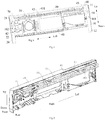
Fig. 1 is a schematic view of a part of a cabinet component for a clothes treatment device according to embodiments of the present disclosure. -
Fig. 2 is a schematic view of another part of a cabinet component for a clothes treatment device according to embodiments of the present disclosure. -
Fig. 3 is an assembly view of a first side plate, a second side plate, a first side connection reinforcement plate and a second side connection reinforcement plate of the cabinet component shown inFig. 1 . -
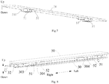
Fig. 4 is a schematic view of an upper connection reinforcement plate of the cabinet component shown inFig. 1 . -
Fig. 5 is an assembly view of a structure shown inFig. 3 and the upper connection reinforcement plate. -
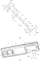
Fig. 6 is schematic view of a control panel of the cabinet component shown inFig. 1 . -
Fig. 7 is a schematic view of a top plate of the cabinet component shown inFig. 1 . -
Fig. 8 is an assembly view of the upper connection reinforcement plate and the top plate of the cabinet component shown inFig. 1 . -
- Cabinet component 100,
-
First side plate 10, positioning hole101, upper flanging 11(21), side flanging 12(22), -
Second side plate 20, sideplate snapping groove 202, - Upper
connection reinforcement plate 30,first snapping hole 301,second snapping hole 302,third snapping hole 303, limitinggroove 304, connecting flanging 31,mounting projection 32,recess portion 33, insertinggroove 331, -
Control panel 40, firstcontrol panel catch 41, secondcontrol panel catch 42,tongue 43,snapping projection 431,positioning column 44, -
Top plate 50,top plate catch 51, clearance gap 511, topplate limiting rib 52, - First side
connection reinforcement plate 60, projecting corner 61(71), threaded hole 62(72), - Second side
connection reinforcement plate 70. - Embodiments of the present disclosure are described in detail hereinafter, and examples of the embodiments are illustrated in drawings. The same or similar elements and the elements having same or similar functions are denoted by like reference numerals throughout the descriptions. The embodiments described herein with reference to the drawings are explanatory, and used to illustrate the present disclosure. The embodiments shall not be construed to limit the present disclosure.
- In the description of the present disclosure, it is to be understood that terms such as "length," "width," "thickness," "upper," "lower," "front," "rear," "left," "right," "horizontal," "top," "inner," and "outer," should be construed to refer to the orientation as then described or as shown in the drawings under discussion. These relative terms are for convenience of description and do not indicate or imply that the present invention be constructed or operated in a particular orientation. Therefore, the above terms should not be construed to limit the present disclosure. In addition, features defined with "first" and "second" can indicate or imply that one or more such features are included. In the description of the present invention, the term "a plurality of' means two or more than two, unless specified otherwise.
- In the description of the present disclosure, it should be understood that, unless specified or limited otherwise, the terms "mounted," "connected," and "coupled" and variations thereof are used broadly and encompass such as mechanical or electrical mountings, connections and couplings, also can be inner mountings, connections and couplings of two components, and further can be direct and indirect mountings, connections, and couplings, which can be understood by those skilled in the art according to the detail embodiment of the present disclosure.
- A cabinet component 100 for a clothes treatment device according to embodiments of the present disclosure is described with reference to
Fig. 1 to Fig, 8 . - As shown in
Fig. 1 to Fig. 8 , a cabinet component 100 for a clothes treatment device according to an embodiment of the present disclosure includes afirst side plate 10, asecond side plate 20, an upperconnection reinforcement plate 30 and acontrol panel 40. - The
first side plate 10 and thesecond side plate 20 are arranged opposite each other. The upperconnection reinforcement plate 30 is arranged between thefirst side plate 10 and thesecond side plate 20. Two ends of the upperconnection reinforcement plate 30 are connected to an upper end of thefirst side plate 10 and an upper end of thesecond side plate 20 respectively. Thecontrol panel 40 is arranged in front of thefirst side plate 10, thesecond side plate 20 and the upperconnection reinforcement plate 30. Thecontrol panel 40 has a rear surface with a control panel snapping portion, the upperconnection reinforcement plate 30 has an upper connection reinforcement plate snapping portion, and the control panel snapping portion is connected to the upper connection reinforcement plate snapping portion by snapping. - As for the cabinet component 100 for a clothes treatment device according to the present disclosure, with the control panel snapping portion on the rear surface of the
control panel 40 and with the upper connection reinforcement plate snapping portion on the upperconnection reinforcement plate 30, thecontrol panel 40 and the upperconnection reinforcement plate 30 can be connected via snapping by means of cooperation of the control panel snapping portion and the upper connection reinforcement plate snapping portion. Therefore, connecting parts, such as screws are omitted, the structure is simplified, the manufacture cost is reduced, and further it is beneficial to efficiency of assembling the cabinet component 100. - As shown in
Fig. 1 and Fig. 2 and combined withFig. 4 andFig. 6 , according to an embodiment of the present disclosure, the control panel snapping portion has a plurality of first control panel catches 41, and the plurality of first control panel catches 41 are arranged along a length direction (a left-right direction shown inFig. 6 ) of thecontrol panel 40 at intervals and extend backward. The upper connection reinforcement plate snapping portion has a plurality of first snapping holes 301, and the plurality of first snappingholes 301 are arranged along a length direction (a left-right direction shown inFig. 6 ) of the upperconnection reinforcement plate 30 at intervals. Positions of the plurality of the first snapping holes 301 correspond to positions of the plurality of first control panel catches 41 one to one, such that the plurality of first control panel catches 41 are snapped into the plurality of first snappingholes 301 one to one. - The
control panel 40 and the upperconnection reinforcement plate 30 not only can be positioned in the left-right direction, but also can be connected reliably without redundant screws, thereby improving efficiency of connection between thecontrol panel 40 and the upperconnection reinforcement plate 30. - As shown in
Fig. 4 andFig. 5 , in some examples, the upperconnection reinforcement plate 30 has a side (such as a front side shown inFig. 5 ), facing thecontrol panel 40, with a connectingflanging 31 which is bent upward. That is the front side of the upperconnection reinforcement plate 30 is bent upward to form the connectingflanging 31 extending along a length direction of the upperconnection reinforcement plate 30. The plurality of first snappingholes 301 are all defined in the connectingflanging 31. - Correspondingly, as shown in
Fig. 6 , thecontrol panel 40 has a rear surface with an upper portion, and the plurality of first control panel catches 41 are arranged on the upper portion. Each firstcontrol panel catch 41 extends backward, such that the first control panel catches 41 are over against the first snapping holes 301, and the first control panel catches 41 can be inserted into the first snapping holes 301, thereby an upper portion of thecontrol panel 40 can be fastened to the front side of the upperconnection reinforcement plate 30. - According to an embodiment of the present disclosure, the rear surface of the
control panel 40 has apositioning column 44 extending backward, one of thefirst side plate 10 and thesecond side plate 20 has a side, facing thecontrol panel 40, with apositioning hole 101 matching thepositioning column 44. - Further, the rear surface of the
control panel 40 has a plurality of second control panel catches 42, and the plurality of second control panel catches 42 are arranged along a width direction (an up-down direction shown inFig. 6 ) of thecontrol panel 40 at intervals and extend backward. The other one of thefirst side plate 10 and thesecond side plate 20 has a side, facing thecontrol panel 40, with a plurality of sideplate snapping grooves 202 matching the second control panel catches 42. - As shown in
Fig. 3 andFig. 6 , thefirst side plate 10 and thesecond side plate 20 are arranged opposite each other and at an interval along the left-right direction. Thefirst side plate 10 is arranged at the left side of thesecond side plate 20. Thefirst side plate 10 has a front side bent toward thesecond side plate 20 to form aside flanging 12. Thesecond side plate 20 has a front side bent toward thefirst side plate 10 to form a side flanging 22. Theside flanging 12 defines thepositioning hole 101, and the side flanging 22 defines the plurality of sideplate snapping grooves 202 which are arranged at intervals along a height direction of thesecond side plate 20. - Correspondingly, the
positioning column 44 matching thepositioning hole 101 is arranged on a left portion of the rear surface of thecontrol panel 40. The plurality of second control panel catches 42 are arranged on a right portion of the rear surface of thecontrol panel 40. Positions of the plurality of sideplate snapping grooves 202 correspond to positions of the plurality of second control panel catches one to one, and the plurality of second control panel catches are snapped into the plurality of sideplate snapping grooves 202 one to one. Therefore, the left portion of thecontrol panel 40 is positioned and mounted to the first side plate, and the right portion of thecontrol panel 40 is fixedly connected to thesecond side plate 20. Connection between the control panel and thefirst side plate 10 and connection between the control panel and thesecond side plate 20 need no connection parts such as screws, which is beneficial to efficiency of assembling. - As shown in
Fig. 4 to Fig. 6 , according to an embodiment of the present disclosure, the upper portion of the rear surface of thecontrol panel 40 has a plurality oftongues 43, and thetongues 43 are arranged at intervals along the length direction of thecontrol panel 40. Each tongue extends along the front-rear direction, and thetongue 43 has a front end fixed to the rear surface of thecontrol panel 40. The upperconnection reinforcement plate 30 has a plurality of second snapping holes 302, and the plurality oftongues 43 are snapped into the plurality of second snapping holes 302 one to one. With the plurality oftongues 43 on thecontrol panel 40, and with the plurality of second snapping holes 302 in the upperconnection reinforcement plate 30, the reliability of connection between thecontrol panel 40 and the upperconnection reinforcement plate 30 can be further improved by means of the plurality oftongues 43 and the plurality of snappingholes 302. - In some examples, each
tongue 43 has an end (a rear end of thetongue 43 shown inFig. 6 ) away from thecontrol panel 40, the end has a lower surface with a snappingprojection 431. The snappingprojection 431 is snapped into a correspondingsecond snapping hole 302, thus connecting thecontrol panel 40 with the upperconnection reinforcement plate 30, and omitting connecting parts such as screws. - As shown in
Fig.1 andFig. 5 with reference toFig. 7 and Fig. 8 , a cabinet component according to a further embodiment of the present disclosure further includes atop plate 50. Thetop plate 50 is mounted above the upperconnection reinforcement plate 30 and pressed against the plurality oftongues 43, thereby clamping each tongue between thetop plate 50 and theupper reinforcement plate 30. Thetop plate 50 can further limit the tongue, thus fully fixing thecontrol panel 40. - In some examples, the
top plate 50 has a lower surface with at least two top plate catches 51 arranged at an interval. The upperconnection reinforcement plate 30 has at least two third snapping holes 303, the top plate catches 51 are snapped into the third snapping holes 303. The third snapping holes 303 may be long holes, and the top plate catches 51 has a plurality of claw portions arranged along a length direction of the long holes. By snapping the at least two top plate catches 51 into the at least two third snapping holes 303, thetop plate 50 can be connected to theupper reinforcement plate 30 via snapping. Connecting parts such as screws can be omitted, which not only improve efficiency of assembly but also reduce manufacture cost. - As shown in
Fig. 7 , in some specific examples, a portion of thetop plate catch 51 is fixedly connected to the lower surface of thetop plate 50, and other portion of thetop plate catch 51 is spaced apart from the lower surface of thetop plate 50 such that clearance gaps 511 can be defined. The top plate catches 51 are inserted into the third snapping holes 303, and at least a portion of the upperconnection reinforcement plate 30 is snapped into the clearance gaps 511. With the clearance gaps 511 defined between the top plate catches 51 and the lower surface of thetop plate 50, connection between thetop plate 50 and theupper reinforcement plate 30 can be more reliable and stable by snapping the top plate catches 51 into the third snapping holes 30 and snapping edges of the third snapping holes 30 into the clearance gaps 511. - In other specific examples, the lower surface of the
top plate 50 is also provided with a topplate limiting rib 52 extending downward, and the upperconnection reinforcement plate 30 defines a limitinggroove 304 matching the topplate limiting rib 52. Thetop plate 50 and the upperconnection reinforcement plate 30 can be positioned before assembling via cooperation between the top plate limiting 52 and the limitinggroove 304, thereby improving efficiency of assembling thetop plate 50 and the upperconnection reinforcement plate 30. - Optionally, the lower surface of the top plate is also provided with a plurality of top
plate limiting ribs 52, and the plurality of topplate limiting ribs 52 are arranged at intervals along a length direction of thetop plate 50. The topplate limiting ribs 52 are arranged in a supposed line connecting the at least two top plate catches 51, thereby facilitating assembling thetop plate 50 and the upperconnection reinforcement plate 30. - In some examples, the upper
connection reinforcement plate 30 has an upper surface with a mountingprojection 32 projecting upward. The second snapping holes 302 and the third snapping holes 303 are defined in a top wall or side wall of the mountingprojection 32. Of course, the second snapping holes 302 and the third snapping holes 303 can also be defined in the top wall or the side wall. Specifically, the first snapping holes 301 extend from the top wall of the mountingprojection 32 to the side wall of the mountingprojection 32, and the second snapping holes 302 also extend from the top wall of the mountingprojection 32 to the side wall of the mountingprojection 32, which is beneficial to snapping connection between the second snapping holes 302 and the snappingprojections 431 of thetongues 43 and snapping connection between the third snapping holes 303 and the top plate catches 51. - Further, the limiting
groove 304 is defined in the top wall of the mountingprojection 32, the topplate limiting rib 52 projects from the lower surface of thetop plate 50, such that the topplate limiting rib 52 can be inserted into the limitinggroove 304, and thetop plate 50 and the upperconnection reinforcement plate 30 can be positioned in advance before mounting. - As shown in
Fig. 3 andFig. 5 , according to an embodiment of the present disclosure, thefirst side plate 10 has an upper end with a first sideconnection reinforcement plate 60 extending toward thesecond side plate 20. Thesecond side plate 20 has an upper end with a second sideconnection reinforcement plate 70 extending toward thefirst side plate 10. The upperconnection reinforcement plate 30 has an end connected with thefirst side plate 10 by means of the first sideconnection reinforcement plate 60, and another end connected with thesecond side plate 20 by means of the second sideconnection reinforcement plate 70. - In some examples, the upper ends of the
first side plate 10 and thesecond side plate 20 are bent toward each other to form upper flangings 11 (21). That is, the upper end of thefirst side plate 10 is bent toward thesecond side plate 20 to form anupper flanging 11 of thefirst side plate 10, and the upper end of thesecond side plate 20 is bent toward thefirst side plate 10 to form anupper flanging 21 of thesecond side plate 20. The first sideconnection reinforcement plate 60 is riveted to theupper flanging 11 of thefirst side plate 10, and the second sideconnection reinforcement plate 70 is riveted to theupper flanging 21 of thesecond side plate 20. - Therefore, not only the upper
connection reinforcement plate 30 can be easily connected to thefirst side plate 10 and thesecond side plate 20, but also the strength and the stability of a structure of the assembledfirst side plate 10,second side plate 20 and upperconnection reinforcement plate 30. - As shown in
Fig. 3 , in some examples, two ends of the upperconnection reinforcement plate 30 are connected to the first sideconnection reinforcement plate 60 and the second sideconnection reinforcement plate 70 by means of threaded connectors respectively. - Specifically, the first side
connection reinforcement plate 60 defines a threadedhole 62, and the upperconnection reinforcement plate 30 has a left end defining a connecting hole which corresponds to the threadedhole 62 in position. The left end of the upperconnection reinforcement plate 30 is arranged on the upper surface of the upperconnection reinforcement plate 30 and connected to the upperconnection reinforcement plate 30 by means of a threaded connector. Similarly, the second sideconnection reinforcement plate 70 defines a threadedhole 72, and the upperconnection reinforcement plate 30 has a right end defining a connecting hole which corresponds to the threadedhole 72 in position. The right end of the upperconnection reinforcement plate 30 is arranged on the upper surface of the upperconnection reinforcement plate 30 and connected to the upperconnection reinforcement plate 30 by means of threaded connector. Connections are convenient and reliable. - With reference to
Fig. 3 andFig. 5 , the first sideconnection reinforcement plate 60 has a right side with a projectingcorner 61, and the projectingcorner 61 extends toward the second sideconnection reinforcement plate 70. The second sideconnection reinforcement plate 70 has a left side with a projectingcorner 71, and the projectingcorner 71 extends toward the first sideconnection reinforcement plate 70. Further, the left end of the upperconnection reinforcement plate 30 defines an insertinggroove 331, and the insertinggroove 331 has an opening toward the first sideconnection reinforcement plate 60. The projectingcorner 61 of the first sideconnection reinforcement plate 60 is inserted in the insertinggroove 331 in the left end of the upperconnection reinforcement plate 30. The right end of the upperconnection reinforcement plate 30 defines an insertinggroove 331, and the insertinggroove 331 has an opening toward the second sideconnection reinforcement plate 70. The projectingcorner 71 of the second sideconnection reinforcement plate 70 is inserted in the insertinggroove 331 in the right end of the upperconnection reinforcement plate 30. Therefore, reliability of connection between the upperconnection reinforcement plate 30 and the first sideconnection reinforcement plate 60 and the second sideconnection reinforcement plate 70 can be further ensured. - In some specific examples, the upper surface of the upper
connection reinforcement plate 30 has a left portion with arecess portion 33 extending downward, and therecess portion 33 has an side (facing the first side reinforcement plate 60) with an opening, thereby defining the insertinggroove 331. Similarly, the upper surface of the upperconnection reinforcement plate 30 has a right portion with arecess portion 33 extending downward, and therecess portion 33 has a side (facing the second side reinforcement plate 70) with an opening, thereby defining the insertinggroove 331. The projectingcorner 61 of the first sideconnection reinforcement plate 60 and the projectingcorner 71 of the second sideconnection reinforcement plate 70 are inserted in the corresponding insertinggrooves 331 respectively. The upperconnection reinforcement plate 30 is simple in structure, and reliability of connection between two ends of the upperconnection reinforcement plate 30 and the first sideconnection reinforcement plate 60 and the second sideconnection reinforcement plate 70 can be conveniently improved. - A specific embodiment of a cabinet component 100 for a clothes treatment device according to the present disclosure is described hereafter with reference to
Fig. 1 to Fig. 8 . - The cabinet component 100 includes a
first side plate 10, asecond side plate 20, an upperconnection reinforcement plate 30, acontrol panel 40, a top plate, a first sideconnection reinforcement plate 60 and a second sideconnection reinforcement plate 70. - The first side plate has a
side flanging 12 with apositioning hole 101. Thesecond side plate 20 has a side flanging with three sideplate snapping grooves 202. The first sideconnection reinforcement plate 60 is riveted to anupper flanging 11 of thefirst side plate 10. The first sideconnection reinforcement plate 60 has a projectingcorner 61 and a threadedhole 62. The second sideconnection reinforcement plate 70 is riveted to anupper flanging 21 of thesecond side plate 10. The second sideconnection reinforcement plate 70 has a projectingcorner 71 and a threadedhole 72. - The upper
connection reinforcement plate 30 has a front side with a connectingflanging 31 which is bent upward. The connectingflanging 31 defines a plurality of first snapping holes 301, and the plurality of first snappingholes 301 are arranged at intervals. The upperconnection reinforcement plate 30 has an upper surface with a mountingprojection 32, and the mountingprojection 32 extends along a length direction of the upperconnection reinforcement plate 30. The mountingprojection 32 defines a plurality of second snapping holes 302, a plurality of third snapping holes 303 and a plurality of limitinggrooves 304. The upperconnection reinforcement plate 30 has two ends with inserting grooves. - The
control panel 40 has a rear surface with an upper portion, and the upper portion is provided with a plurality of first control panel catches 41 extending backward and a plurality oftongues 43 extending backward. Eachtongue 43 has a lower surface with a snappingprojection 431. The length of thetongue 43 is greater than that of the firstcontrol panel catch 41. Thecontrol panel 40 has a rear surface, the rear surface has a left portion with apositioning column 44 extending backward and a right portion with a plurality of second control panel catches 42. - The
top plate 50 has a lower surface with a plurality of top plate catches 51 arranged at intervals along a length direction of thetop plate 50. Eachtop plate catch 51 and the lower surface of thetop plate 50 define a clearance gap 511. The lower surface of thetop plate 50 is further provided with a plurality of topplate limiting ribs 52. - During assembling, connecting holes of the upper
connection reinforcement plate 30 is aligned with the threadedhole 62 of the first sideconnection reinforcement plate 60 and the threadedhole 72 of the second sideconnection reinforcement plate 70 respectively, and threaded connectors are used for fixing. At the same time, the projectingcorner 61 of the first sideconnection reinforcement plate 60 is snapped into the insertinggroove 331 in the left end of the upperconnection reinforcement plate 30, and the projectingcorner 71 of the second sideconnection reinforcement plate 70 is snapped into the insertinggroove 331 in the right end of the upperconnection reinforcement plate 30. - Then, the first side
connection reinforcement plate 60 is riveted to theupper flanging 11 of thefirst side plate 10, the second sideconnection reinforcement plate 70 is riveted to theupper flanging 21 of thesecond side plate 20, thereby fixing the upperconnection reinforcement plate 30 to thefirst side plate 10 and thesecond side plate 20 of a cabinet. - And then, the first control panel catches 41 on the
control panel 40 are snapped into the first snapping holes 301 in the upperconnection reinforcement plate 30, the second control panel catches 42 of thecontrol panel 40 are snapped into the sideplate snapping grooves 202 in thesecond side plate 20, and thepositioning column 44 oncontrol panel 40 is snapped into thepositioning hole 101 in thefirst side plate 10. At the same time, the snappingprojections 431 of thetongues 43 on thecontrol panel 40 are hooked on the second snapping holes 302 in the upperconnection reinforcement plate 30. Therefore, thecontrol panel 40 is fixed to the upperconnection reinforcement plate 30, thefirst side plate 10 and thesecond side plate 20 of the cabinet. - Finally, the top plate catches 51 on the
top plate 50 are snapped into the third snapping holes 303 in the upperconnection reinforcement plate 30, the topplate limiting ribs 52 on thetop plate 50 are inserted into the limitinggrooves 304 in the upperconnection reinforcement plate 30. The top plate is pressed on thetongues 43 to further limit thetongues 43, such that thecontrol panel 40 can be fully fixed. - A clothes treatment device according to embodiments of the present disclosure includes the cabinet component 100 for the clothes treatment device according to the above embodiments. The clothes treatment device herein can be a washing machine such as a front-loading washer and a top-loading washer, or a clothes dryer or a clothes washer-dryer.
- Since the cabinet component 100 for the clothes treatment device according to the above embodiments can achieve the above technical effects, the clothes treatment device according to embodiments of the present disclosure also can achieve thee above technical effects. That is the clothes treatment device has a simple structure, less components, low manufacture cost and high assembling efficiency.
- Other configurations and operations for the clothes treatment device according to the embodiments are known to those skilled in the art and will not described in detail.
- Reference throughout this specification to "an embodiment," "some embodiments," "illustrative embodiment", "an example," "a specific example," or "some examples," means that a particular feature, structure, material, or characteristic described in connection with the embodiment or example is included in at least one embodiment or example of the present disclosure. Thus, the appearances of the phrases are not necessarily referring to the same embodiment or example of the present disclosure. Furthermore, the particular features, structures, materials, or characteristics may be combined in any suitable manner in one or more embodiments or examples.
- Although explanatory embodiments have been shown and described, it would be appreciated by those skilled in the art that the above embodiments cannot be construed to limit the present disclosure, and changes, alternatives, and modifications can be made in the embodiments without departing from the principles and scope of the present disclosure.
Claims (13)
- A cabinet component (100) for a clothes treatment device, comprising:a first side plate (10) and a second side plate (20) arranged opposite each other;an upper connection reinforcement plate (30), arranged between the first side plate (10) and the second side plate (20), and having two ends connected to an upper end of the first side plate (10) and an upper end of the second side plate (20) respectively;a control panel (40), arranged in front of the first side plate (10), the second side plate (20) and the upper connection reinforcement plate (30);wherein the control panel (40) has a rear surface with a control panel snapping portion, the upper connection reinforcement plate (30) has an upper connection reinforcement plate snapping portion, and the control panel snapping portion is connected to the upper connection reinforcement plate snapping portion by snapping;wherein the control panel snapping portion comprises a plurality of first control panel catches (41) arranged along a length direction of the control panel (40) at intervals and extend backward, the upper connection reinforcement plate snapping portion comprises a plurality of first snapping holes (301), and the plurality of first control panel catches (41) are snapped into the plurality of first snapping holes (301) one to one; andcharacterized in that the upper connection reinforcement plate (30) has a side facing the control panel (40), the side is provided with a connecting flanging (31), the connecting flanging (31) is bent upward and extends along a length direction of the upper connection reinforcement plate (30), and the plurality of first snapping holes (301) are all defined in the connecting flanging (31).
- The cabinet component (100) according to claim 1, wherein the rear surface of the control panel (40) has a positioning column (44) extending backward, one of the first side plate (10) and the second side plate (20) has a side, facing the control panel (40), with a positioning hole (101) matching the positioning column (44).
- The cabinet component (100) according to claim 2, wherein the rear surface of the control panel (40) has a plurality of second control panel catches (42) arranged along a width direction of the control panel (40) at intervals and extend backward, the other one of the first side plate (10) and the second side plate (20) has a side, facing the control panel (40), with a plurality of side plate snapping grooves (202) matching the second control panel catches (42).
- The cabinet component (100) according to claim 1, wherein the rear surface of the control panel (40) has an upper portion with a plurality of tongues (43) arranged along the length direction of the control panel (40) at intervals and extend backward, the upper connection reinforcement plate (30) defines a plurality of second snapping holes (302), and the plurality of tongues (43) are snapped into the plurality of second snapping holes (302) one to one.
- The cabinet component (100) according to claim 4, wherein each tongue (43) has an end away from the control panel (40), the end has a lower surface with a snapping projection (431), and the snapping projection (431) is snapped into a corresponding second snapping hole (302).
- The cabinet component (100) according to claim 4, further comprising a top plate (50), wherein the top plate (50) is mounted above the upper connection reinforcement plate (30) and pressed against the plurality of tongues (43), and each tongue (43) is clamped between the top plate (50) and the upper reinforcement plate (30).
- The cabinet component (100) according to claim 6, wherein the top plate (50) has a lower surface with at least two top plate catches (51) arranged at an interval, the upper connection reinforcement plate (30) defines at least two third snapping holes (303), and the top plate catches (51) are snapped into the third snapping holes (303).
- The cabinet component (100) according to claim 7, wherein a portion of the top plate catch (51) is fixedly connected to the lower surface of the top plate (50), other portion of the top plate catch (51) is spaced apart from the lower surface of the top plate (50) such that clearance gaps (511) can be defined, the top plate catches (51) are inserted into the third snapping holes (303), and at least a portion of the upper connection reinforcement plate (30) is snapped into the clearance gaps (511).
- The cabinet component (100) according to claim 7, wherein the lower surface of the top plate (50) further has a top plate limiting rib (52) extending downward, the upper connection reinforcement plate (30) defines a limiting groove (304) matching the top plate limiting rib (52), and the top plate limiting ribs (52) are arranged in a supposed line connecting the at least two top plate catches (51).
- The cabinet component (100) according to claim 9, wherein the upper connection reinforcement plate (30) has an upper surface with a mounting projection (32) projecting upward, the second snapping holes (302) and the third snapping holes (303) are defined in a top wall and/or side wall of the mounting projection (32), and the limiting groove (304) is defined in the top wall of the mounting projection (32).
- The cabinet component (100) according to claim 1, wherein the first side plate (10) has an upper end with a first side connection reinforcement plate (60) extending toward the second side plate (20), the second side plate (20) has an upper end with a second side connection reinforcement plate (70) extending toward the first side plate (10), the upper connection reinforcement plate (30) has an end connected with the first side plate (10) by means of the first side connection reinforcement plate (60), and another end connected with the second side plate (20) by means of the second side connection reinforcement plate (70).
- The cabinet component (100) according to claim 11, wherein the upper ends of the first side plate (10) and the second side plate (20) are bent toward each other to form upper flangings (11, 21), the first side connection reinforcement plate (60) and the second side connection reinforcement plate (70) are riveted to the corresponding upper flangings (11, 21) respectively;
two ends of the upper connection reinforcement plate (30) are connected to the first side connection reinforcement plate (60) and the second side connection reinforcement plate (70) by means of threaded connectors respectively;
the first side connection reinforcement plate (60) and the second side connection reinforcement plate (70) have sides facing each other, the sides are provided with projecting corners (61, 71), the two ends of the upper connection reinforcement plate (30) define inserting grooves (331), and the projecting corner (61, 71) are inserted in the corresponding inserting grooves (331) respectively;
the upper surface of the upper connection reinforcement plate (30) has two recess portions (33) extending downward, the recess portions (33) have side walls with openings, the recess portions (33) define the inserting grooves (331), and the projecting corner (61, 71) are inserted in the recess portions (33) through the openings. - A clothes treatment device, comprising the cabinet component (100) according to any one of claims 1 to 12.
Applications Claiming Priority (2)
| Application Number | Priority Date | Filing Date | Title |
|---|---|---|---|
| CN201820567377.9U CN208250717U (en) | 2018-04-19 | 2018-04-19 | Device for clothing processing and its box assembly |
| CN201810354002.9A CN108360224B (en) | 2018-04-19 | 2018-04-19 | Clothes treatment device and box assembly thereof |
Publications (2)
| Publication Number | Publication Date |
|---|---|
| EP3556928A1 EP3556928A1 (en) | 2019-10-23 |
| EP3556928B1 true EP3556928B1 (en) | 2020-09-16 |
Family
ID=66239878
Family Applications (1)
| Application Number | Title | Priority Date | Filing Date |
|---|---|---|---|
| EP19170214.1A Active EP3556928B1 (en) | 2018-04-19 | 2019-04-18 | Clothes treatment device and cabinet component therefor |
Country Status (1)
| Country | Link |
|---|---|
| EP (1) | EP3556928B1 (en) |
Family Cites Families (3)
| Publication number | Priority date | Publication date | Assignee | Title |
|---|---|---|---|---|
| CA2623649A1 (en) * | 2008-02-29 | 2009-08-29 | Mabe Canada Inc. | Laundry appliance front control panel assembly |
| EP2329072A2 (en) * | 2008-09-09 | 2011-06-08 | Arçelik Anonim Sirketi | Control panel assembly for a washer/dryer |
| CN104775279B (en) * | 2014-01-10 | 2018-11-09 | 青岛海尔滚筒洗衣机有限公司 | A kind of retaining mechanism for drum washing machine distributor |
-
2019
- 2019-04-18 EP EP19170214.1A patent/EP3556928B1/en active Active
Non-Patent Citations (1)
| Title |
|---|
| None * |
Also Published As
| Publication number | Publication date |
|---|---|
| EP3556928A1 (en) | 2019-10-23 |
Similar Documents
| Publication | Publication Date | Title |
|---|---|---|
| EP3940134B1 (en) | Frame component for clothes treatment device and clothes treatment device | |
| CN108360224B (en) | Clothes treatment device and box assembly thereof | |
| US20050122011A1 (en) | Cabinet structure of home appliance | |
| CN204959421U (en) | A dryer that is used for lock subassembly of dryer and has it | |
| CN108457054B (en) | Cabinet assembly of clothes treatment device, fixing piece and clothes treatment device | |
| EP3556928B1 (en) | Clothes treatment device and cabinet component therefor | |
| CN1955365B (en) | Washing machine | |
| CN221285460U (en) | Oven | |
| CN111394950B (en) | Support frame and clothes treating device | |
| CN219555277U (en) | Display panel mounting structure and household appliance | |
| CN204199047U (en) | Laundry drum thermomechanical components | |
| KR100434295B1 (en) | structure for assembling control panel assembly in drum-type washing machine | |
| CN111058232B (en) | Interference suppressor and washing machine | |
| CN219802768U (en) | Quick mounting structure of encoder | |
| CN210868423U (en) | Automatically controlled mounting structure, motor and electrical equipment | |
| CN108078406B (en) | Support and household appliance | |
| CN212305834U (en) | Automatically controlled box mounting structure and domestic appliance equipment | |
| CN112050546A (en) | Display components and refrigerators | |
| CN108797012A (en) | Washing machine | |
| CN216474077U (en) | washing machine | |
| CN222601446U (en) | Copper bar suite for connecting convenient preassembled inter-section connectors | |
| EP3754091B1 (en) | Laundry treatment apparatus | |
| CN223921817U (en) | Drawer type washing equipment | |
| CN105483977B (en) | Laundry drum thermomechanical components | |
| CN216891627U (en) | Washing machine |
Legal Events
| Date | Code | Title | Description |
|---|---|---|---|
| PUAI | Public reference made under article 153(3) epc to a published international application that has entered the european phase |
Free format text: ORIGINAL CODE: 0009012 |
|
| STAA | Information on the status of an ep patent application or granted ep patent |
Free format text: STATUS: THE APPLICATION HAS BEEN PUBLISHED |
|
| AK | Designated contracting states |
Kind code of ref document: A1 Designated state(s): AL AT BE BG CH CY CZ DE DK EE ES FI FR GB GR HR HU IE IS IT LI LT LU LV MC MK MT NL NO PL PT RO RS SE SI SK SM TR |
|
| AX | Request for extension of the european patent |
Extension state: BA ME |
|
| STAA | Information on the status of an ep patent application or granted ep patent |
Free format text: STATUS: REQUEST FOR EXAMINATION WAS MADE |
|
| 17P | Request for examination filed |
Effective date: 20191030 |
|
| RBV | Designated contracting states (corrected) |
Designated state(s): AL AT BE BG CH CY CZ DE DK EE ES FI FR GB GR HR HU IE IS IT LI LT LU LV MC MK MT NL NO PL PT RO RS SE SI SK SM TR |
|
| RAP1 | Party data changed (applicant data changed or rights of an application transferred) |
Owner name: WUXI LITTLE SWAN ELECTRIC CO., LTD. |
|
| REG | Reference to a national code |
Ref country code: DE Ref legal event code: R079 Ref document number: 602019000689 Country of ref document: DE Free format text: PREVIOUS MAIN CLASS: D06F0039120000 Ipc: D06F0034280000 |
|
| GRAP | Despatch of communication of intention to grant a patent |
Free format text: ORIGINAL CODE: EPIDOSNIGR1 |
|
| STAA | Information on the status of an ep patent application or granted ep patent |
Free format text: STATUS: GRANT OF PATENT IS INTENDED |
|
| RIC1 | Information provided on ipc code assigned before grant |
Ipc: D06F 34/28 20200101AFI20200610BHEP Ipc: D06F 39/12 20060101ALN20200610BHEP |
|
| INTG | Intention to grant announced |
Effective date: 20200707 |
|
| GRAS | Grant fee paid |
Free format text: ORIGINAL CODE: EPIDOSNIGR3 |
|
| GRAA | (expected) grant |
Free format text: ORIGINAL CODE: 0009210 |
|
| STAA | Information on the status of an ep patent application or granted ep patent |
Free format text: STATUS: THE PATENT HAS BEEN GRANTED |
|
| AK | Designated contracting states |
Kind code of ref document: B1 Designated state(s): AL AT BE BG CH CY CZ DE DK EE ES FI FR GB GR HR HU IE IS IT LI LT LU LV MC MK MT NL NO PL PT RO RS SE SI SK SM TR |
|
| REG | Reference to a national code |
Ref country code: GB Ref legal event code: FG4D |
|
| REG | Reference to a national code |
Ref country code: CH Ref legal event code: EP |
|
| REG | Reference to a national code |
Ref country code: DE Ref legal event code: R096 Ref document number: 602019000689 Country of ref document: DE |
|
| REG | Reference to a national code |
Ref country code: IE Ref legal event code: FG4D |
|
| REG | Reference to a national code |
Ref country code: AT Ref legal event code: REF Ref document number: 1314265 Country of ref document: AT Kind code of ref document: T Effective date: 20201015 |
|
| PG25 | Lapsed in a contracting state [announced via postgrant information from national office to epo] |
Ref country code: NO Free format text: LAPSE BECAUSE OF FAILURE TO SUBMIT A TRANSLATION OF THE DESCRIPTION OR TO PAY THE FEE WITHIN THE PRESCRIBED TIME-LIMIT Effective date: 20201216 Ref country code: BG Free format text: LAPSE BECAUSE OF FAILURE TO SUBMIT A TRANSLATION OF THE DESCRIPTION OR TO PAY THE FEE WITHIN THE PRESCRIBED TIME-LIMIT Effective date: 20201216 Ref country code: SE Free format text: LAPSE BECAUSE OF FAILURE TO SUBMIT A TRANSLATION OF THE DESCRIPTION OR TO PAY THE FEE WITHIN THE PRESCRIBED TIME-LIMIT Effective date: 20200916 Ref country code: GR Free format text: LAPSE BECAUSE OF FAILURE TO SUBMIT A TRANSLATION OF THE DESCRIPTION OR TO PAY THE FEE WITHIN THE PRESCRIBED TIME-LIMIT Effective date: 20201217 Ref country code: FI Free format text: LAPSE BECAUSE OF FAILURE TO SUBMIT A TRANSLATION OF THE DESCRIPTION OR TO PAY THE FEE WITHIN THE PRESCRIBED TIME-LIMIT Effective date: 20200916 Ref country code: HR Free format text: LAPSE BECAUSE OF FAILURE TO SUBMIT A TRANSLATION OF THE DESCRIPTION OR TO PAY THE FEE WITHIN THE PRESCRIBED TIME-LIMIT Effective date: 20200916 |
|
| REG | Reference to a national code |
Ref country code: AT Ref legal event code: MK05 Ref document number: 1314265 Country of ref document: AT Kind code of ref document: T Effective date: 20200916 |
|
| REG | Reference to a national code |
Ref country code: NL Ref legal event code: MP Effective date: 20200916 |
|
| PG25 | Lapsed in a contracting state [announced via postgrant information from national office to epo] |
Ref country code: RS Free format text: LAPSE BECAUSE OF FAILURE TO SUBMIT A TRANSLATION OF THE DESCRIPTION OR TO PAY THE FEE WITHIN THE PRESCRIBED TIME-LIMIT Effective date: 20200916 Ref country code: LV Free format text: LAPSE BECAUSE OF FAILURE TO SUBMIT A TRANSLATION OF THE DESCRIPTION OR TO PAY THE FEE WITHIN THE PRESCRIBED TIME-LIMIT Effective date: 20200916 |
|
| REG | Reference to a national code |
Ref country code: LT Ref legal event code: MG4D |
|
| PG25 | Lapsed in a contracting state [announced via postgrant information from national office to epo] |
Ref country code: EE Free format text: LAPSE BECAUSE OF FAILURE TO SUBMIT A TRANSLATION OF THE DESCRIPTION OR TO PAY THE FEE WITHIN THE PRESCRIBED TIME-LIMIT Effective date: 20200916 Ref country code: RO Free format text: LAPSE BECAUSE OF FAILURE TO SUBMIT A TRANSLATION OF THE DESCRIPTION OR TO PAY THE FEE WITHIN THE PRESCRIBED TIME-LIMIT Effective date: 20200916 Ref country code: PT Free format text: LAPSE BECAUSE OF FAILURE TO SUBMIT A TRANSLATION OF THE DESCRIPTION OR TO PAY THE FEE WITHIN THE PRESCRIBED TIME-LIMIT Effective date: 20210118 Ref country code: CZ Free format text: LAPSE BECAUSE OF FAILURE TO SUBMIT A TRANSLATION OF THE DESCRIPTION OR TO PAY THE FEE WITHIN THE PRESCRIBED TIME-LIMIT Effective date: 20200916 Ref country code: LT Free format text: LAPSE BECAUSE OF FAILURE TO SUBMIT A TRANSLATION OF THE DESCRIPTION OR TO PAY THE FEE WITHIN THE PRESCRIBED TIME-LIMIT Effective date: 20200916 Ref country code: SM Free format text: LAPSE BECAUSE OF FAILURE TO SUBMIT A TRANSLATION OF THE DESCRIPTION OR TO PAY THE FEE WITHIN THE PRESCRIBED TIME-LIMIT Effective date: 20200916 |
|
| PG25 | Lapsed in a contracting state [announced via postgrant information from national office to epo] |
Ref country code: PL Free format text: LAPSE BECAUSE OF FAILURE TO SUBMIT A TRANSLATION OF THE DESCRIPTION OR TO PAY THE FEE WITHIN THE PRESCRIBED TIME-LIMIT Effective date: 20200916 Ref country code: IS Free format text: LAPSE BECAUSE OF FAILURE TO SUBMIT A TRANSLATION OF THE DESCRIPTION OR TO PAY THE FEE WITHIN THE PRESCRIBED TIME-LIMIT Effective date: 20210116 Ref country code: ES Free format text: LAPSE BECAUSE OF FAILURE TO SUBMIT A TRANSLATION OF THE DESCRIPTION OR TO PAY THE FEE WITHIN THE PRESCRIBED TIME-LIMIT Effective date: 20200916 Ref country code: AL Free format text: LAPSE BECAUSE OF FAILURE TO SUBMIT A TRANSLATION OF THE DESCRIPTION OR TO PAY THE FEE WITHIN THE PRESCRIBED TIME-LIMIT Effective date: 20200916 Ref country code: AT Free format text: LAPSE BECAUSE OF FAILURE TO SUBMIT A TRANSLATION OF THE DESCRIPTION OR TO PAY THE FEE WITHIN THE PRESCRIBED TIME-LIMIT Effective date: 20200916 |
|
| REG | Reference to a national code |
Ref country code: DE Ref legal event code: R097 Ref document number: 602019000689 Country of ref document: DE |
|
| PG25 | Lapsed in a contracting state [announced via postgrant information from national office to epo] |
Ref country code: SK Free format text: LAPSE BECAUSE OF FAILURE TO SUBMIT A TRANSLATION OF THE DESCRIPTION OR TO PAY THE FEE WITHIN THE PRESCRIBED TIME-LIMIT Effective date: 20200916 |
|
| PLBE | No opposition filed within time limit |
Free format text: ORIGINAL CODE: 0009261 |
|
| STAA | Information on the status of an ep patent application or granted ep patent |
Free format text: STATUS: NO OPPOSITION FILED WITHIN TIME LIMIT |
|
| 26N | No opposition filed |
Effective date: 20210617 |
|
| PG25 | Lapsed in a contracting state [announced via postgrant information from national office to epo] |
Ref country code: DK Free format text: LAPSE BECAUSE OF FAILURE TO SUBMIT A TRANSLATION OF THE DESCRIPTION OR TO PAY THE FEE WITHIN THE PRESCRIBED TIME-LIMIT Effective date: 20200916 Ref country code: SI Free format text: LAPSE BECAUSE OF FAILURE TO SUBMIT A TRANSLATION OF THE DESCRIPTION OR TO PAY THE FEE WITHIN THE PRESCRIBED TIME-LIMIT Effective date: 20200916 |
|
| PG25 | Lapsed in a contracting state [announced via postgrant information from national office to epo] |
Ref country code: IT Free format text: LAPSE BECAUSE OF FAILURE TO SUBMIT A TRANSLATION OF THE DESCRIPTION OR TO PAY THE FEE WITHIN THE PRESCRIBED TIME-LIMIT Effective date: 20200916 |
|
| PG25 | Lapsed in a contracting state [announced via postgrant information from national office to epo] |
Ref country code: MC Free format text: LAPSE BECAUSE OF FAILURE TO SUBMIT A TRANSLATION OF THE DESCRIPTION OR TO PAY THE FEE WITHIN THE PRESCRIBED TIME-LIMIT Effective date: 20200916 |
|
| PG25 | Lapsed in a contracting state [announced via postgrant information from national office to epo] |
Ref country code: LU Free format text: LAPSE BECAUSE OF NON-PAYMENT OF DUE FEES Effective date: 20210418 |
|
| REG | Reference to a national code |
Ref country code: BE Ref legal event code: MM Effective date: 20210430 |
|
| PG25 | Lapsed in a contracting state [announced via postgrant information from national office to epo] |
Ref country code: FR Free format text: LAPSE BECAUSE OF NON-PAYMENT OF DUE FEES Effective date: 20210430 |
|
| PG25 | Lapsed in a contracting state [announced via postgrant information from national office to epo] |
Ref country code: IE Free format text: LAPSE BECAUSE OF NON-PAYMENT OF DUE FEES Effective date: 20210418 |
|
| PG25 | Lapsed in a contracting state [announced via postgrant information from national office to epo] |
Ref country code: IS Free format text: LAPSE BECAUSE OF FAILURE TO SUBMIT A TRANSLATION OF THE DESCRIPTION OR TO PAY THE FEE WITHIN THE PRESCRIBED TIME-LIMIT Effective date: 20210116 |
|
| PG25 | Lapsed in a contracting state [announced via postgrant information from national office to epo] |
Ref country code: BE Free format text: LAPSE BECAUSE OF NON-PAYMENT OF DUE FEES Effective date: 20210430 |
|
| REG | Reference to a national code |
Ref country code: CH Ref legal event code: PL |
|
| PG25 | Lapsed in a contracting state [announced via postgrant information from national office to epo] |
Ref country code: LI Free format text: LAPSE BECAUSE OF NON-PAYMENT OF DUE FEES Effective date: 20220430 Ref country code: CH Free format text: LAPSE BECAUSE OF NON-PAYMENT OF DUE FEES Effective date: 20220430 |
|
| PG25 | Lapsed in a contracting state [announced via postgrant information from national office to epo] |
Ref country code: NL Free format text: LAPSE BECAUSE OF NON-PAYMENT OF DUE FEES Effective date: 20200923 Ref country code: CY Free format text: LAPSE BECAUSE OF FAILURE TO SUBMIT A TRANSLATION OF THE DESCRIPTION OR TO PAY THE FEE WITHIN THE PRESCRIBED TIME-LIMIT Effective date: 20200916 |
|
| PG25 | Lapsed in a contracting state [announced via postgrant information from national office to epo] |
Ref country code: HU Free format text: LAPSE BECAUSE OF FAILURE TO SUBMIT A TRANSLATION OF THE DESCRIPTION OR TO PAY THE FEE WITHIN THE PRESCRIBED TIME-LIMIT; INVALID AB INITIO Effective date: 20190418 |
|
| GBPC | Gb: european patent ceased through non-payment of renewal fee |
Effective date: 20230418 |
|
| PG25 | Lapsed in a contracting state [announced via postgrant information from national office to epo] |
Ref country code: GB Free format text: LAPSE BECAUSE OF NON-PAYMENT OF DUE FEES Effective date: 20230418 |
|
| PG25 | Lapsed in a contracting state [announced via postgrant information from national office to epo] |
Ref country code: GB Free format text: LAPSE BECAUSE OF NON-PAYMENT OF DUE FEES Effective date: 20230418 |
|
| PG25 | Lapsed in a contracting state [announced via postgrant information from national office to epo] |
Ref country code: MK Free format text: LAPSE BECAUSE OF FAILURE TO SUBMIT A TRANSLATION OF THE DESCRIPTION OR TO PAY THE FEE WITHIN THE PRESCRIBED TIME-LIMIT Effective date: 20200916 |
|
| PG25 | Lapsed in a contracting state [announced via postgrant information from national office to epo] |
Ref country code: TR Free format text: LAPSE BECAUSE OF FAILURE TO SUBMIT A TRANSLATION OF THE DESCRIPTION OR TO PAY THE FEE WITHIN THE PRESCRIBED TIME-LIMIT Effective date: 20200916 |
|
| PG25 | Lapsed in a contracting state [announced via postgrant information from national office to epo] |
Ref country code: MT Free format text: LAPSE BECAUSE OF FAILURE TO SUBMIT A TRANSLATION OF THE DESCRIPTION OR TO PAY THE FEE WITHIN THE PRESCRIBED TIME-LIMIT Effective date: 20200916 |
|
| PGFP | Annual fee paid to national office [announced via postgrant information from national office to epo] |
Ref country code: DE Payment date: 20250417 Year of fee payment: 7 |