EP3556724A1 - Beverage discharge cock, valve rod, and beverage dispenser - Google Patents
Beverage discharge cock, valve rod, and beverage dispenser Download PDFInfo
- Publication number
- EP3556724A1 EP3556724A1 EP16924113.0A EP16924113A EP3556724A1 EP 3556724 A1 EP3556724 A1 EP 3556724A1 EP 16924113 A EP16924113 A EP 16924113A EP 3556724 A1 EP3556724 A1 EP 3556724A1
- Authority
- EP
- European Patent Office
- Prior art keywords
- channel
- valve
- seal
- valve rod
- beverage
- Prior art date
- Legal status (The legal status is an assumption and is not a legal conclusion. Google has not performed a legal analysis and makes no representation as to the accuracy of the status listed.)
- Granted
Links
Images



Classifications
-
- B—PERFORMING OPERATIONS; TRANSPORTING
- B67—OPENING, CLOSING OR CLEANING BOTTLES, JARS OR SIMILAR CONTAINERS; LIQUID HANDLING
- B67D—DISPENSING, DELIVERING OR TRANSFERRING LIQUIDS, NOT OTHERWISE PROVIDED FOR
- B67D3/00—Apparatus or devices for controlling flow of liquids under gravity from storage containers for dispensing purposes
- B67D3/04—Liquid-dispensing taps or cocks adapted to seal and open tapping holes of casks, e.g. for beer
- B67D3/043—Liquid-dispensing taps or cocks adapted to seal and open tapping holes of casks, e.g. for beer with a closing element having a linear movement, in a direction perpendicular to the seat
-
- B—PERFORMING OPERATIONS; TRANSPORTING
- B67—OPENING, CLOSING OR CLEANING BOTTLES, JARS OR SIMILAR CONTAINERS; LIQUID HANDLING
- B67D—DISPENSING, DELIVERING OR TRANSFERRING LIQUIDS, NOT OTHERWISE PROVIDED FOR
- B67D3/00—Apparatus or devices for controlling flow of liquids under gravity from storage containers for dispensing purposes
- B67D3/04—Liquid-dispensing taps or cocks adapted to seal and open tapping holes of casks, e.g. for beer
-
- B—PERFORMING OPERATIONS; TRANSPORTING
- B67—OPENING, CLOSING OR CLEANING BOTTLES, JARS OR SIMILAR CONTAINERS; LIQUID HANDLING
- B67D—DISPENSING, DELIVERING OR TRANSFERRING LIQUIDS, NOT OTHERWISE PROVIDED FOR
- B67D1/00—Apparatus or devices for dispensing beverages on draught
- B67D1/04—Apparatus utilising compressed air or other gas acting directly or indirectly on beverages in storage containers
-
- B—PERFORMING OPERATIONS; TRANSPORTING
- B67—OPENING, CLOSING OR CLEANING BOTTLES, JARS OR SIMILAR CONTAINERS; LIQUID HANDLING
- B67D—DISPENSING, DELIVERING OR TRANSFERRING LIQUIDS, NOT OTHERWISE PROVIDED FOR
- B67D1/00—Apparatus or devices for dispensing beverages on draught
- B67D1/08—Details
- B67D1/12—Flow or pressure control devices or systems, e.g. valves, gas pressure control, level control in storage containers
- B67D1/127—Froth control
-
- B—PERFORMING OPERATIONS; TRANSPORTING
- B67—OPENING, CLOSING OR CLEANING BOTTLES, JARS OR SIMILAR CONTAINERS; LIQUID HANDLING
- B67D—DISPENSING, DELIVERING OR TRANSFERRING LIQUIDS, NOT OTHERWISE PROVIDED FOR
- B67D1/00—Apparatus or devices for dispensing beverages on draught
- B67D1/08—Details
- B67D1/12—Flow or pressure control devices or systems, e.g. valves, gas pressure control, level control in storage containers
- B67D1/127—Froth control
- B67D1/1275—Froth control promoting froth
-
- B—PERFORMING OPERATIONS; TRANSPORTING
- B67—OPENING, CLOSING OR CLEANING BOTTLES, JARS OR SIMILAR CONTAINERS; LIQUID HANDLING
- B67D—DISPENSING, DELIVERING OR TRANSFERRING LIQUIDS, NOT OTHERWISE PROVIDED FOR
- B67D1/00—Apparatus or devices for dispensing beverages on draught
- B67D1/08—Details
- B67D1/12—Flow or pressure control devices or systems, e.g. valves, gas pressure control, level control in storage containers
- B67D1/14—Reducing valves or control taps
- B67D1/1405—Control taps
- B67D1/1411—Means for controlling the build-up of foam in the container to be filled
-
- B—PERFORMING OPERATIONS; TRANSPORTING
- B67—OPENING, CLOSING OR CLEANING BOTTLES, JARS OR SIMILAR CONTAINERS; LIQUID HANDLING
- B67D—DISPENSING, DELIVERING OR TRANSFERRING LIQUIDS, NOT OTHERWISE PROVIDED FOR
- B67D1/00—Apparatus or devices for dispensing beverages on draught
- B67D1/08—Details
- B67D1/12—Flow or pressure control devices or systems, e.g. valves, gas pressure control, level control in storage containers
- B67D1/14—Reducing valves or control taps
- B67D1/1405—Control taps
- B67D1/145—Control taps comprising a valve shutter movable in a direction perpendicular to the valve seat
Definitions
- the present invention relates to a beverage discharge cock, a valve rod, and a beverage dispenser.
- PTL 1 describes a method of decreasing the diameter of a foaming hole, without decreasing the flow rate of beer flowing through a channel hole, by forming a plurality of foaming holes in a valve rod, thereby forming fine creamy foam.
- the basic concept of the invention described in PTL 1 is to make the diameter of the foaming hole as small as possible, and increase the number of foaming holes in order to suppress a decrease in flow rate of beer flowing through the channel hole caused by the decrease in diameter.
- the present inventors conducted an experiment by expecting that the foam density increases when the diameter of the foaming hole is decreased, but the foaming density did not increase even when the diameter of the foaming hole was decreased. More specifically, the present inventors decreased the diameter of the foaming hole to 1.2 mm, 1.0 mm, 0.7 mm, and 0.5 mm, and evaluated a change in foam density. However, no significant effect was found on an increase in foam density resulting from a decrease in diameter of the foaming hole. In addition, the foam density obtained when the diameter of the foaming hole was 0.5 mm, that is, the smallest diameter among the evaluation targets, was lower than the foaming density obtained when the diameter of the foaming hole was 1.2 mm or 1.0 mm. The foam density was evaluated by imaging foam collected by a vessel by using a microscope, cutting out a 1-mm square region from the obtained image, and counting bubbles in the region.
- the first aspect of the present invention is a beverage discharge cock to be attached to a beverage supply source
- the beverage discharge cock includes a valve main body including a hole and a valve seat arranged in an end portion of the hole, a valve rod slidably arranged in the hole, and including a valve body that forms a first valve together with the valve seat of the valve main body, and a first seal, and a movable part slidably arranged in the hole, and including a second seal facing the first seal, the second seal forming a second valve together with the first seal of the valve rod, wherein the valve rod includes a first channel extending through the valve body, and one or a plurality of second channels extending from the first seal to the first channel, and the second channel includes a first portion, and a second portion arranged between the first seal and the first portion, and a diameter of the second portion is smaller than a diameter of the first portion.
- the second aspect of the present invention is a valve rod to be incorporated into a beverage discharge cock to be attached to a beverage supply source, wherein the valve rod includes a valve body and a seal, the valve rod includes a first channel extending through the valve body, and one or a plurality of second channels extending from the seal to the first channel, and the second channel includes a first portion, and a second portion arranged between the first seal and the first portion, and a diameter of the second portion is smaller than a diameter of the first portion.
- the third aspect of the present invention is a beverage dispenser
- the beverage dispenser includes a beverage discharge cock to be attached to a beverage supply source
- the beverage discharge cock includes a valve main body including a hole and a valve seat arranged in an end portion of the hole, a valve rod slidably arranged in the hole, and including a valve body that forms a first valve together with the valve seat of the valve main body, and a first seal, and a movable part slidably arranged in the hole, and including a second seal facing the first seal, the second seal forming a second valve together with the first seal of the valve rod
- the valve rod includes a first channel extending through the valve body, and one or a plurality of second channels extending from the first seal to the first channel, and the second channel includes a first portion, and a second portion arranged between the first seal and the first portion, and a diameter of the second portion is smaller than a diameter of the first portion.
- the beverage dispenser can also include a cooling unit for cooling a beverage
- the present invention provides the beverage discharge cock, the valve rod, and the beverage dispenser advantageous in forming fine creamy foam.
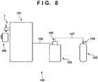
- Fig. 8 shows a beverage discharge apparatus 100 of the preferred embodiment of the present invention.
- the beverage discharge apparatus 100 includes a beverage dispenser 101, a supply head 102, and a pressure regulator 104.
- the pressure regulator 104 is attached to a valve of a carbon dioxide cylinder 105.
- the pressure regulator 104 reduces the pressure of carbon dioxide supplied from the carbon dioxide cylinder 105, and supplies the carbon dioxide to the supply head 102 through a hose 107.
- the supply head 102 is attached to a valve of a beverage transport vessel (for example, a barrel) 103 as a beverage supply source.
- the supply head 102 supplies a beverage such as beer in the beverage transport vessel 103 to the beverage dispenser 101 through a hose 108 by pushing the beverage by the pressure of the carbon dioxide.
- the beverage dispenser 101 has a beverage discharge cock 1.
- the beverage dispenser 101 causes a cooling unit to cool the beverage supplied from the beverage transport vessel 103 via the supply head 102 and the hose 108, and discharges the beverage into a beverage providing vessel 106 such as a beer mug through the beverage discharge cock 1.
- Figs. 1 to 3 show the beverage discharge cock 1.
- Fig. 1 shows a standby state
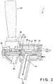
- Fig. 2 shows a discharge state
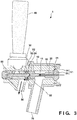
- Fig. 3 shows a foaming state.
- the beverage discharge cock 1 includes a housing 50 to be attached to the main body of the beverage dispenser 101, a valve main body 10, a valve rod 20, a movable part 30, a lever 40, and a spring 60.
- the valve main body 10 includes a hole 12, and a valve seat 14 arranged in the end portion of the hole 12.
- the valve main body 10 also includes a foaming hole 80 for discharging foam of a beverage.
- the valve main body 10 may also be formed as a part integrated with the housing 50.
- the valve rod 20 is slidably arranged in the hole 12 of the valve main body 10.
- the valve rod 20 includes a valve body 25 that forms a first valve V1 together with the valve seat 14 of the valve main body 10, and a first seal 24.
- the first valve V1 is a valve for controlling the discharge of a beverage such as beer.
- the movable part 30 is slidably arranged in the hole 12 of the valve main body 10.
- the movable part 30 has a second seal 32 facing the first seal 24 of the valve rod 20.
- the second seal 32 forms a second valve V2 together with the first seal 24 of the valve rod 20.
- the second valve V2 is a valve for controlling the supply (foaming) of foam of a beverage.
- the valve rod 20 includes a first channel 21 extending through the valve body 25, and one or a plurality of second channels 22 extending from the first seal 24 to the first channel 21.
- the housing 50 includes a discharge hole 70 for discharging a beverage. In the standby state as shown in Fig. 1 , the first seal 24 of the valve rod 20 and the second seal 32 of the movable part 30 are in contact with each other. Also, in the standby state, the valve body 25 of the valve rod 20 is in contact with the valve seat 14 of the valve main body 10.
- the lever 40 When discharging a beverage as shown in Fig. 2 , the lever 40 is pivoted counterclockwise in Fig. 2 , so the movable part 30 moves to the right in Fig. 2 . Since the second seal 32 of the movable part 30 and the first seal 24 of the valve rod 20 are in contact with each other, when the movable part 30 moves to the right in Fig. 2 , the valve rod 20 also moves to the right accordingly.
- This forms a gap (channel) between the valve seat 14 of the valve main body 10 and the valve body 25 of the valve rod 20, and a beverage supplied from the main body of the beverage dispenser 101 is supplied to the discharge hole 70 through the gap between the valve seat 14 and the valve body 25, and discharged through the discharge hole 70.
- Fig. 4 shows the valve rod 20 in an enlarged scale.
- the beverage discharge cock 1 or the valve rod 20 of this embodiment has a feature in the structure of the second channel 22.
- Fig. 5 shows a comparative example of the second channel 22.
- a portion indicated by A' shows a portion indicated by A in an enlarged scale.
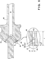
- Fig. 6 shows the second channel 22 in the beverage discharge cock 1 or the valve rod 20 of this embodiment.
- a portion indicated by B' shows a portion indicated by B in an enlarged scale.
- the second channel 22 has a predetermined diameter ⁇ .
- the second channel 22 of this embodiment includes a first portion 221, and a second portion 222 arranged between the first seal 24 and the first portion 221.
- a diameter ⁇ 2 of the second portion 222 is smaller than a diameter ⁇ 1 of the first portion 221.
- the second portion 222 functions as an orifice for decreasing the diameter of the second channel 22. That is, the second channel 22 of this embodiment has an orifice.
- the number of the second channels 22 is preferably 1, 2, 3, or 4, but is not limited to these numbers.
- the axial direction of the second channel 22 is typically a direction intersecting the axial direction of the first channel 21.
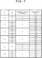
- Fig. 7 shows the effects of the formation of the orifice (second portion 221) in the second channel 22.
- "FOAM DENSITY RATIO" shown in Fig. 7 is an index indicating the effect of the formation of the orifice (second portion 221) in the second channel 22, and represents the foam density of each sample according to this embodiment by % when the foam density of the comparative example is 100%. Note that the experiment was conducted over a plurality of days, so the foam density of the comparative example was measured on each experimental day, and the foam density ratio of each sample according to this embodiment was calculated by assuming that the foam density of the comparative example was 100%.
- the foam density was evaluated by imaging foam collected by a vessel by using a microscope, cutting out a 1-mm square region from the obtained image, and counting bubbles in the region. It is possible to regard that a higher foam density means finer creamier foam. Evaluation by the foam density is excellent as objective evaluation.
- the diameter ⁇ 2 of the second portion 222 (the orifice) was 0.5 to 0.8 mm, and the diameter ⁇ 1 of the first portion 221 was 2.0 mm.
- the number of the second channels 22 was 1 to 4 in this embodiment. All the effects shown in Fig. 7 exceed 100%, that is, foam densities higher than that of the comparative example were obtained.
- the foam density is insensitive to the diameter ⁇ 1 of the first portion 221 at least when the diameter ⁇ 1 of the first portion 221 falls within the range from 1.5 to 2.5 mm. It is estimated that good results are obtained even when the diameter ⁇ 1 of the first portion 221 falls outside the range from 1.5 to 2.5 mm.
- the foam density is insensitive to the length L of the second channel 22 at least when the length L of the second channel 22 falls within the range from 5 to 8 mm. It is estimated that good results are obtained even when the length L of the second channel 22 falls outside the range from 5 to 8 mm.
- the length L2 of the second portion 222 is preferably within a range from 0.5 to 2.5 mm.
- the diameter ⁇ 2 of the second portion 222 is preferably within a range from 0.5 to 0.8 mm, and more preferably 0.6 to 0.8 mm.
- the number of the second channels 22 (second portions 222) is preferably 1, 2, 3, or 4. It is favorable that the number of the second channels 22 (second portions 222) is 2, the length L2 of the second portion is within a range from 0.5 to 2.5 mm, and the diameter ⁇ 2 of the second portion 222 is within a range from 0.6 to 0.8 mm.
- the axial direction of the second channel 22 is typically a direction intersecting the axial direction of the first channel 21, and the angle at which the axial direction of the second channel 22 intersects the axial direction of the first channel 21 is preferably within a range from 20° to 60°.
- the axial direction of the second portion 222 is preferably equal to the axial direction of the first portion 221.
- valve main body 10: valve main body, 12: hole, 14: valve seat, 20: valve rod, 21: first channel, 22: second channel, 24: first seal, 25: valve body, 30: movable part, 32: second seal, 40: lever, 50: housing, 60: spring, 70: discharge hole, 80: foaming hole, 100: beverage discharge apparatus, V1: first valve, V2: second valve, 221: first portion, 222: second portion
Landscapes
- Engineering & Computer Science (AREA)
- Mechanical Engineering (AREA)
- Devices For Dispensing Beverages (AREA)
Abstract
Description
- The present invention relates to a beverage discharge cock, a valve rod, and a beverage dispenser.
- When discharging a carbonated beverage such as beer, it is important to form fine creamy foam.
PTL 1 describes a method of decreasing the diameter of a foaming hole, without decreasing the flow rate of beer flowing through a channel hole, by forming a plurality of foaming holes in a valve rod, thereby forming fine creamy foam. - PTL 1: Japanese Patent Laid-Open No.
9-2590 - It is understood that the basic concept of the invention described in
PTL 1 is to make the diameter of the foaming hole as small as possible, and increase the number of foaming holes in order to suppress a decrease in flow rate of beer flowing through the channel hole caused by the decrease in diameter. - The present inventors conducted an experiment by expecting that the foam density increases when the diameter of the foaming hole is decreased, but the foaming density did not increase even when the diameter of the foaming hole was decreased. More specifically, the present inventors decreased the diameter of the foaming hole to 1.2 mm, 1.0 mm, 0.7 mm, and 0.5 mm, and evaluated a change in foam density. However, no significant effect was found on an increase in foam density resulting from a decrease in diameter of the foaming hole. In addition, the foam density obtained when the diameter of the foaming hole was 0.5 mm, that is, the smallest diameter among the evaluation targets, was lower than the foaming density obtained when the diameter of the foaming hole was 1.2 mm or 1.0 mm. The foam density was evaluated by imaging foam collected by a vessel by using a microscope, cutting out a 1-mm square region from the obtained image, and counting bubbles in the region.
- It is an object of the present invention to provide a beverage discharge cock, a valve rod, and a beverage dispenser advantageous in forming fine creamy foam.
- The first aspect of the present invention is a beverage discharge cock to be attached to a beverage supply source, and the beverage discharge cock includes a valve main body including a hole and a valve seat arranged in an end portion of the hole, a valve rod slidably arranged in the hole, and including a valve body that forms a first valve together with the valve seat of the valve main body, and a first seal, and a movable part slidably arranged in the hole, and including a second seal facing the first seal, the second seal forming a second valve together with the first seal of the valve rod, wherein the valve rod includes a first channel extending through the valve body, and one or a plurality of second channels extending from the first seal to the first channel, and the second channel includes a first portion, and a second portion arranged between the first seal and the first portion, and a diameter of the second portion is smaller than a diameter of the first portion.
- The second aspect of the present invention is a valve rod to be incorporated into a beverage discharge cock to be attached to a beverage supply source, wherein the valve rod includes a valve body and a seal, the valve rod includes a first channel extending through the valve body, and one or a plurality of second channels extending from the seal to the first channel, and the second channel includes a first portion, and a second portion arranged between the first seal and the first portion, and a diameter of the second portion is smaller than a diameter of the first portion.
- The third aspect of the present invention is a beverage dispenser, the beverage dispenser includes a beverage discharge cock to be attached to a beverage supply source, the beverage discharge cock includes a valve main body including a hole and a valve seat arranged in an end portion of the hole, a valve rod slidably arranged in the hole, and including a valve body that forms a first valve together with the valve seat of the valve main body, and a first seal, and a movable part slidably arranged in the hole, and including a second seal facing the first seal, the second seal forming a second valve together with the first seal of the valve rod, the valve rod includes a first channel extending through the valve body, and one or a plurality of second channels extending from the first seal to the first channel, and the second channel includes a first portion, and a second portion arranged between the first seal and the first portion, and a diameter of the second portion is smaller than a diameter of the first portion. The beverage dispenser can also include a cooling unit for cooling a beverage.
- The present invention provides the beverage discharge cock, the valve rod, and the beverage dispenser advantageous in forming fine creamy foam.
-
-
Fig. 1 is a view showing the arrangement (in a standby state) of a beverage discharge cock; -
Fig. 2 is a view showing the arrangement (in a discharge state) of the beverage discharge cock; -
Fig. 3 is a view showing the arrangement (in a foaming state) of the beverage discharge cock; -
Fig. 4 is a view showing the arrangement of a valve rod to be incorporated into the beverage discharge cock; -
Fig. 5 is a view showing a second channel of a comparative example; -
Fig. 6 is a view showing a second channel of an embodiment; -
Fig. 7 is a view showing evaluation results; and -
Fig. 8 is a view showing an outline of the arrangement of a beverage discharge apparatus. - A preferred embodiment of the present invention will be explained below with reference to the accompanying drawings.
-
Fig. 8 shows abeverage discharge apparatus 100 of the preferred embodiment of the present invention. Thebeverage discharge apparatus 100 includes abeverage dispenser 101, asupply head 102, and apressure regulator 104. Thepressure regulator 104 is attached to a valve of acarbon dioxide cylinder 105. Thepressure regulator 104 reduces the pressure of carbon dioxide supplied from thecarbon dioxide cylinder 105, and supplies the carbon dioxide to thesupply head 102 through ahose 107. Thesupply head 102 is attached to a valve of a beverage transport vessel (for example, a barrel) 103 as a beverage supply source. Thesupply head 102 supplies a beverage such as beer in thebeverage transport vessel 103 to thebeverage dispenser 101 through ahose 108 by pushing the beverage by the pressure of the carbon dioxide. Thebeverage dispenser 101 has abeverage discharge cock 1. Thebeverage dispenser 101 causes a cooling unit to cool the beverage supplied from thebeverage transport vessel 103 via thesupply head 102 and thehose 108, and discharges the beverage into abeverage providing vessel 106 such as a beer mug through thebeverage discharge cock 1. -
Figs. 1 to 3 show thebeverage discharge cock 1.Fig. 1 shows a standby state,Fig. 2 shows a discharge state, andFig. 3 shows a foaming state. Thebeverage discharge cock 1 includes ahousing 50 to be attached to the main body of thebeverage dispenser 101, a valvemain body 10, avalve rod 20, amovable part 30, alever 40, and aspring 60. - The valve
main body 10 includes ahole 12, and avalve seat 14 arranged in the end portion of thehole 12. The valvemain body 10 also includes afoaming hole 80 for discharging foam of a beverage. The valvemain body 10 may also be formed as a part integrated with thehousing 50. Thevalve rod 20 is slidably arranged in thehole 12 of the valvemain body 10. Thevalve rod 20 includes avalve body 25 that forms a first valve V1 together with thevalve seat 14 of the valvemain body 10, and afirst seal 24. The first valve V1 is a valve for controlling the discharge of a beverage such as beer. Themovable part 30 is slidably arranged in thehole 12 of the valvemain body 10. Themovable part 30 has asecond seal 32 facing thefirst seal 24 of thevalve rod 20. Thesecond seal 32 forms a second valve V2 together with thefirst seal 24 of thevalve rod 20. The second valve V2 is a valve for controlling the supply (foaming) of foam of a beverage. Thevalve rod 20 includes afirst channel 21 extending through thevalve body 25, and one or a plurality ofsecond channels 22 extending from thefirst seal 24 to thefirst channel 21. Thehousing 50 includes adischarge hole 70 for discharging a beverage. In the standby state as shown inFig. 1 , thefirst seal 24 of thevalve rod 20 and thesecond seal 32 of themovable part 30 are in contact with each other. Also, in the standby state, thevalve body 25 of thevalve rod 20 is in contact with thevalve seat 14 of the valvemain body 10. - When discharging a beverage as shown in
Fig. 2 , thelever 40 is pivoted counterclockwise inFig. 2 , so themovable part 30 moves to the right inFig. 2 . Since thesecond seal 32 of themovable part 30 and thefirst seal 24 of thevalve rod 20 are in contact with each other, when themovable part 30 moves to the right inFig. 2 , thevalve rod 20 also moves to the right accordingly. This forms a gap (channel) between thevalve seat 14 of the valvemain body 10 and thevalve body 25 of thevalve rod 20, and a beverage supplied from the main body of thebeverage dispenser 101 is supplied to thedischarge hole 70 through the gap between thevalve seat 14 and thevalve body 25, and discharged through thedischarge hole 70. - When foaming the beverage as shown in
Fig. 3 , thelever 40 is pivoted clockwise inFig. 3 , so themovable part 30 moves to the left inFig. 3 while compressing thespring 60. When themovable part 30 moves to the left, a gap (channel) is formed between thefirst seal 24 of thevalve rod 20 and thesecond seal 32 of themovable part 30, so the beverage supplied from the main body of thebeverage dispenser 101 is supplied to the gap between thefirst seal 24 and thesecond seal 32 through thefirst channel 21 and thesecond channel 22 of thevalve rod 20. In this state, the beverage is foamed. The foamed beverage is pushed out through thefoaming hole 80. -
Fig. 4 shows thevalve rod 20 in an enlarged scale. Thebeverage discharge cock 1 or thevalve rod 20 of this embodiment has a feature in the structure of thesecond channel 22.Fig. 5 shows a comparative example of thesecond channel 22. A portion indicated by A' shows a portion indicated by A in an enlarged scale.Fig. 6 shows thesecond channel 22 in thebeverage discharge cock 1 or thevalve rod 20 of this embodiment. A portion indicated by B' shows a portion indicated by B in an enlarged scale. - In the comparative example shown in
Fig. 5 , thesecond channel 22 has a predetermined diameter φ. On the other hand, thesecond channel 22 of this embodiment includes afirst portion 221, and asecond portion 222 arranged between thefirst seal 24 and thefirst portion 221. A diameter φ2 of thesecond portion 222 is smaller than a diameter φ1 of thefirst portion 221. Thesecond portion 222 functions as an orifice for decreasing the diameter of thesecond channel 22. That is, thesecond channel 22 of this embodiment has an orifice. By forming the orifice in thesecond channel 22, the flow rate of a beverage increases in the orifice (second portion 222), and fine foam is efficiently formed when this beverage is pushed out into the gap between thefirst seal 24 and thesecond seal 32. It is also possible to suppress a decrease in flow rate of the beverage by forming thefirst portion 221 having a diameter larger than that of thesecond portion 222. - By forming the orifice in the
second channel 22, it is possible to form fine creamy foam compared to the comparative example as will be described later. The number of thesecond channels 22 is preferably 1, 2, 3, or 4, but is not limited to these numbers. The axial direction of thesecond channel 22 is typically a direction intersecting the axial direction of thefirst channel 21. -
Fig. 7 shows the effects of the formation of the orifice (second portion 221) in thesecond channel 22. "FOAM DENSITY RATIO" shown inFig. 7 is an index indicating the effect of the formation of the orifice (second portion 221) in thesecond channel 22, and represents the foam density of each sample according to this embodiment by % when the foam density of the comparative example is 100%. Note that the experiment was conducted over a plurality of days, so the foam density of the comparative example was measured on each experimental day, and the foam density ratio of each sample according to this embodiment was calculated by assuming that the foam density of the comparative example was 100%. - The foam density was evaluated by imaging foam collected by a vessel by using a microscope, cutting out a 1-mm square region from the obtained image, and counting bubbles in the region. It is possible to regard that a higher foam density means finer creamier foam. Evaluation by the foam density is excellent as objective evaluation. In the comparative example, a length L (in the axial direction) of the
second channel 22 = 6.25 mm, a diameter φ of thesecond channel 22 = 1.0 mm, and the number of the second channels = 1. - In this embodiment, a length L2 (in the axial direction) of the second portion of the
second channel 22 = 0.5 to 2.5 mm, and the length L of thesecond channel 22, which is the sum of the length of thesecond portion 222 and the length of thefirst portion 221 = 6.25 mm. Also, in this embodiment, the diameter φ2 of the second portion 222 (the orifice) was 0.5 to 0.8 mm, and the diameter φ1 of thefirst portion 221 was 2.0 mm. In addition, the number of thesecond channels 22 was 1 to 4 in this embodiment. All the effects shown inFig. 7 exceed 100%, that is, foam densities higher than that of the comparative example were obtained. - Note that although not shown in
Fig. 7 , the foam density is insensitive to the diameter φ1 of thefirst portion 221 at least when the diameter φ1 of thefirst portion 221 falls within the range from 1.5 to 2.5 mm. It is estimated that good results are obtained even when the diameter φ1 of thefirst portion 221 falls outside the range from 1.5 to 2.5 mm. Note also that although not shown inFig. 7 , the foam density is insensitive to the length L of thesecond channel 22 at least when the length L of thesecond channel 22 falls within the range from 5 to 8 mm. It is estimated that good results are obtained even when the length L of thesecond channel 22 falls outside the range from 5 to 8 mm. - From the results shown in
Fig. 7 , the length L2 of thesecond portion 222 is preferably within a range from 0.5 to 2.5 mm. The diameter φ2 of thesecond portion 222 is preferably within a range from 0.5 to 0.8 mm, and more preferably 0.6 to 0.8 mm. The number of the second channels 22 (second portions 222) is preferably 1, 2, 3, or 4. It is favorable that the number of the second channels 22 (second portions 222) is 2, the length L2 of the second portion is within a range from 0.5 to 2.5 mm, and the diameter φ2 of thesecond portion 222 is within a range from 0.6 to 0.8 mm. - The axial direction of the
second channel 22 is typically a direction intersecting the axial direction of thefirst channel 21, and the angle at which the axial direction of thesecond channel 22 intersects the axial direction of thefirst channel 21 is preferably within a range from 20° to 60°. The axial direction of thesecond portion 222 is preferably equal to the axial direction of thefirst portion 221. - 1: beverage discharge cock, 10: valve main body, 12: hole, 14: valve seat, 20: valve rod, 21: first channel, 22: second channel, 24: first seal, 25: valve body, 30: movable part, 32: second seal, 40: lever, 50: housing, 60: spring, 70: discharge hole, 80: foaming hole, 100: beverage discharge apparatus, V1: first valve, V2: second valve, 221: first portion, 222: second portion
Claims (23)
- A beverage discharge cock to be attached to a beverage supply source, comprising:a valve main body including a hole and a valve seat arranged in an end portion of the hole;a valve rod slidably arranged in the hole, and including a valve body that forms a first valve together with the valve seat of the valve main body, and a first seal; anda movable part slidably arranged in the hole, and including a second seal facing the first seal, the second seal forming a second valve together with the first seal of the valve rod,wherein the valve rod includes a first channel extending through the valve body, and one or a plurality of second channels extending from the first seal to the first channel, andthe second channel includes a first portion, and a second portion arranged between the first seal and the first portion, and a diameter of the second portion is smaller than a diameter of the first portion.
- The beverage discharge cock according to claim 1, wherein a length of the second portion is within a range from 0.5 to 2.5 mm.
- The beverage discharge cock according to claim 1 or 2, wherein a diameter of the second portion is within a range from 0.5 to 0.8 mm.
- The beverage discharge cock according to claim 1 or 2, wherein the diameter of the second portion is within a range from 0.6 to 0.8 mm.
- The beverage discharge cock according to any one of claims 1 to 3, wherein the number of the second channels is one of 1, 2, 3, and 4.
- The beverage discharge cock according to claim 1, wherein the number of the second channels is 2, a length of the second portion is within a range from 0.5 to 2.5 mm, and a diameter of the second portion is within a range from 0.6 to 0.8mm.
- The beverage discharge cock according to any one of claims 1 to 6, wherein a length of the second channel is within a range from 5 to 8 mm.
- The beverage discharge cock according to any one of claims 1 to 7, wherein a diameter of the first portion is within a range from 1.5 to 2.5 mm.
- The beverage discharge cock according to any one of claims 1 to 8, wherein an axial direction of the second channel is a direction intersecting an axial direction of the first channel.
- The beverage discharge cock according to claim 9, wherein an angle at which the axial direction of the second channel intersects the axial direction of the first channel is within a range from 20° to 60°.
- The beverage discharge cock according to any one of claims 1 to 10, wherein the axial direction of the second portion is equal to the axial direction of the first portion.
- A valve rod to be incorporated into a beverage discharge cock to be attached to a beverage supply source, wherein
the valve rod includes a valve body and a seal,
the valve rod includes a first channel extending through the valve body, and one or a plurality of second channels extending from the seal to the first channel, and
the second channel includes a first portion, and a second portion arranged between the seal and the first portion, and a diameter of the second portion is smaller than a diameter of the first portion. - The valve rod according to claim 12, wherein a length of the second portion is within a range from 0.5 to 2.5 mm.
- The valve rod according to claim 12 or 13, wherein a diameter of the second portion is within a range from 0.5 to 0.8 mm.
- The valve rod according to claim 12 or 13, wherein the diameter of the second portion is within a range from 0.6 to 0.8 mm.
- The valve rod according to any one of claims 12 to 15, wherein the number of the second channels is one of 1, 2, 3, and 4.
- The valve rod according to claim 12, wherein the number of the second channels is 2, a length of the second portion is within a range from 0.5 to 2.5 mm, and a diameter of the second portion is within a range from 0.6 to 0.8 mm.
- The valve rod according to any one of claims 12 to 17, wherein a length of the second channel is within a range from 5 to 8 mm.
- The valve rod according to any one of claims 12 to 18, wherein a diameter of the first portion is within a range from 1.5 to 2.5 mm.
- The valve rod according to any one of claims 12 to 19, wherein an axial direction of the second channel is a direction intersecting an axial direction of the first channel.
- The valve rod according to claim 20, wherein an angle at which the axial direction of the second channel intersects the axial direction of the first channel is within a range from 20° to 60°.
- The valve rod according to any one of claims 12 to 21, wherein the axial direction of the second portion is equal to the axial direction of the first portion.
- A beverage dispenser comprising a beverage discharge cock as defined in any one of claims 1 to 11.
Applications Claiming Priority (1)
| Application Number | Priority Date | Filing Date | Title |
|---|---|---|---|
| PCT/JP2016/087038 WO2018109834A1 (en) | 2016-12-13 | 2016-12-13 | Beverage discharge cock, valve rod, and beverage dispenser |
Publications (4)
| Publication Number | Publication Date |
|---|---|
| EP3556724A1 true EP3556724A1 (en) | 2019-10-23 |
| EP3556724A4 EP3556724A4 (en) | 2020-08-05 |
| EP3556724C0 EP3556724C0 (en) | 2024-04-24 |
| EP3556724B1 EP3556724B1 (en) | 2024-04-24 |
Family
ID=62559436
Family Applications (1)
| Application Number | Title | Priority Date | Filing Date |
|---|---|---|---|
| EP16924113.0A Active EP3556724B1 (en) | 2016-12-13 | 2016-12-13 | Beverage discharge cock, valve rod, and beverage dispenser |
Country Status (9)
| Country | Link |
|---|---|
| US (1) | US10919755B2 (en) |
| EP (1) | EP3556724B1 (en) |
| JP (1) | JP6583979B2 (en) |
| KR (1) | KR102241410B1 (en) |
| CN (1) | CN110072799B (en) |
| AU (1) | AU2016432203B2 (en) |
| CA (1) | CA3046737C (en) |
| RU (1) | RU2713704C1 (en) |
| WO (1) | WO2018109834A1 (en) |
Cited By (1)
| Publication number | Priority date | Publication date | Assignee | Title |
|---|---|---|---|---|
| CZ308723B6 (en) * | 2019-11-20 | 2021-03-24 | Plzeňský Prazdroj, a. s. | Beverage tap with one-way valve |
Families Citing this family (3)
| Publication number | Priority date | Publication date | Assignee | Title |
|---|---|---|---|---|
| CA3046737C (en) * | 2016-12-13 | 2023-11-21 | Asahi Breweries, Ltd. | Beverage discharge cock, valve rod, and beverage dispenser |
| CN113950459B (en) * | 2020-05-15 | 2022-07-29 | 株式会社日特 | Injection valve |
| JP2024027902A (en) * | 2022-08-19 | 2024-03-01 | アサヒビール株式会社 | Beverage dispensing faucet, valve stem and beverage dispenser |
Family Cites Families (13)
| Publication number | Priority date | Publication date | Assignee | Title |
|---|---|---|---|---|
| US2416581A (en) * | 1944-10-19 | 1947-02-25 | Herman H Harr | Mixing and dispensing faucet |
| FR2593878B1 (en) * | 1986-02-05 | 1988-11-25 | Kronenbourg Brasseries | PRESSURE PULL VALVE OF A CARBONATE BEVERAGE, ESPECIALLY BEER WITH CONTROLLED FOAM |
| JPH092590A (en) | 1995-06-26 | 1997-01-07 | Kirin Brewery Co Ltd | Tap with foaming function |
| JP4493879B2 (en) * | 2001-05-08 | 2010-06-30 | ホシザキ電機株式会社 | Foamed beverage pouring cock |
| JP4570283B2 (en) * | 2001-06-08 | 2010-10-27 | ホシザキ電機株式会社 | Foamed beverage pouring cock |
| JP4060169B2 (en) * | 2002-11-27 | 2008-03-12 | ホシザキ電機株式会社 | Foam pouring cock |
| US8034372B2 (en) | 2003-03-05 | 2011-10-11 | Nestec, Ltd. | Dietary supplement for athletic pets |
| JP4520322B2 (en) * | 2005-01-31 | 2010-08-04 | 福島工業株式会社 | Cocktail for sparkling beverage |
| RU2364568C1 (en) * | 2008-03-11 | 2009-08-20 | Закрытое Акционерное Общество "Новосибирскпродмаш" | Device for hand dispensing of foamy and/or carbonated beverages |
| JP5993170B2 (en) * | 2012-03-23 | 2016-09-14 | 株式会社リード | Beer extraction cock |
| KR101413093B1 (en) * | 2013-02-01 | 2014-07-01 | 최승우 | Valve slider for beer dispenser valve |
| JP6208292B2 (en) * | 2016-06-14 | 2017-10-04 | 麒麟麦酒株式会社 | Tap device for beverage dispenser and foam generation method |
| CA3046737C (en) | 2016-12-13 | 2023-11-21 | Asahi Breweries, Ltd. | Beverage discharge cock, valve rod, and beverage dispenser |
-
2016
- 2016-12-13 CA CA3046737A patent/CA3046737C/en active Active
- 2016-12-13 RU RU2019120522A patent/RU2713704C1/en active
- 2016-12-13 KR KR1020197017477A patent/KR102241410B1/en not_active Expired - Fee Related
- 2016-12-13 JP JP2018556066A patent/JP6583979B2/en active Active
- 2016-12-13 CN CN201680091507.XA patent/CN110072799B/en active Active
- 2016-12-13 WO PCT/JP2016/087038 patent/WO2018109834A1/en not_active Ceased
- 2016-12-13 EP EP16924113.0A patent/EP3556724B1/en active Active
- 2016-12-13 AU AU2016432203A patent/AU2016432203B2/en active Active
-
2019
- 2019-06-10 US US16/435,598 patent/US10919755B2/en active Active
Cited By (1)
| Publication number | Priority date | Publication date | Assignee | Title |
|---|---|---|---|---|
| CZ308723B6 (en) * | 2019-11-20 | 2021-03-24 | Plzeňský Prazdroj, a. s. | Beverage tap with one-way valve |
Also Published As
| Publication number | Publication date |
|---|---|
| KR102241410B1 (en) | 2021-04-16 |
| EP3556724A4 (en) | 2020-08-05 |
| NZ755207A (en) | 2023-08-25 |
| AU2016432203B2 (en) | 2022-09-29 |
| US20190292039A1 (en) | 2019-09-26 |
| RU2713704C1 (en) | 2020-02-07 |
| US10919755B2 (en) | 2021-02-16 |
| AU2016432203A1 (en) | 2019-07-25 |
| EP3556724C0 (en) | 2024-04-24 |
| CA3046737A1 (en) | 2018-06-21 |
| JPWO2018109834A1 (en) | 2019-10-24 |
| KR20190084108A (en) | 2019-07-15 |
| CN110072799B (en) | 2021-06-18 |
| JP6583979B2 (en) | 2019-10-02 |
| WO2018109834A1 (en) | 2018-06-21 |
| CA3046737C (en) | 2023-11-21 |
| EP3556724B1 (en) | 2024-04-24 |
| CN110072799A (en) | 2019-07-30 |
Similar Documents
| Publication | Publication Date | Title |
|---|---|---|
| US10919755B2 (en) | Beverage discharge cock, valve rod, and beverage dispenser | |
| US2143565A (en) | Beer stabilizer coil control | |
| JP2011110853A (en) | Liquid circulating system | |
| HK40009922A (en) | Beverage discharge cock, valve rod, and beverage dispenser | |
| HK40009922B (en) | Beverage discharge cock, valve rod, and beverage dispenser | |
| NZ755207B2 (en) | Beverage discharge cock, valve rod, and beverage dispenser | |
| JP6792729B1 (en) | Stopper for continuous casting and continuous casting method | |
| JP2019218142A (en) | Beverage discharge cock, valve rod, and beverage dispenser | |
| US2011249A (en) | Bullet | |
| JP5993170B2 (en) | Beer extraction cock | |
| JP6901123B2 (en) | Draft cock | |
| JP7094026B2 (en) | Bubble forming device | |
| JP4520322B2 (en) | Cocktail for sparkling beverage | |
| JPWO2018109836A1 (en) | Beverage dispensing cock, valve stem and beverage dispenser | |
| CN108430909A (en) | Beverage dispensing unit comprising a dispensing valve with a piston | |
| JP2013254253A (en) | Pressure regulating valve | |
| JP6737589B2 (en) | Carbonated water pouring valve | |
| US965555A (en) | Dispensing device for soda-fountains. | |
| EP4691963A1 (en) | Beverage server and dispensing nozzle | |
| JP2016030641A (en) | Carbonated water discharging valve and drinking water supply device using the valve | |
| WO2024038791A1 (en) | Beverage pouring cock, valve rod, and beverage dispenser | |
| JP6155117B2 (en) | Former pump | |
| CN112923086B (en) | Pressure regulating valve and pipeline transmission system | |
| CA3287544A1 (en) | Beverage server and pouring nozzle | |
| JP2005201342A (en) | High pressure gas filling system and high pressure gas filling method |
Legal Events
| Date | Code | Title | Description |
|---|---|---|---|
| STAA | Information on the status of an ep patent application or granted ep patent |
Free format text: STATUS: THE INTERNATIONAL PUBLICATION HAS BEEN MADE |
|
| PUAI | Public reference made under article 153(3) epc to a published international application that has entered the european phase |
Free format text: ORIGINAL CODE: 0009012 |
|
| STAA | Information on the status of an ep patent application or granted ep patent |
Free format text: STATUS: REQUEST FOR EXAMINATION WAS MADE |
|
| 17P | Request for examination filed |
Effective date: 20190610 |
|
| AK | Designated contracting states |
Kind code of ref document: A1 Designated state(s): AL AT BE BG CH CY CZ DE DK EE ES FI FR GB GR HR HU IE IS IT LI LT LU LV MC MK MT NL NO PL PT RO RS SE SI SK SM TR |
|
| AX | Request for extension of the european patent |
Extension state: BA ME |
|
| DAV | Request for validation of the european patent (deleted) | ||
| DAX | Request for extension of the european patent (deleted) | ||
| REG | Reference to a national code |
Ref country code: HK Ref legal event code: DE Ref document number: 40009922 Country of ref document: HK |
|
| A4 | Supplementary search report drawn up and despatched |
Effective date: 20200702 |
|
| RIC1 | Information provided on ipc code assigned before grant |
Ipc: B67D 1/04 20060101AFI20200626BHEP Ipc: B67D 1/14 20060101ALI20200626BHEP Ipc: B67D 1/12 20060101ALI20200626BHEP Ipc: B67D 3/04 20060101ALI20200626BHEP |
|
| GRAP | Despatch of communication of intention to grant a patent |
Free format text: ORIGINAL CODE: EPIDOSNIGR1 |
|
| STAA | Information on the status of an ep patent application or granted ep patent |
Free format text: STATUS: GRANT OF PATENT IS INTENDED |
|
| INTG | Intention to grant announced |
Effective date: 20240109 |
|
| GRAS | Grant fee paid |
Free format text: ORIGINAL CODE: EPIDOSNIGR3 |
|
| GRAA | (expected) grant |
Free format text: ORIGINAL CODE: 0009210 |
|
| STAA | Information on the status of an ep patent application or granted ep patent |
Free format text: STATUS: THE PATENT HAS BEEN GRANTED |
|
| AK | Designated contracting states |
Kind code of ref document: B1 Designated state(s): AL AT BE BG CH CY CZ DE DK EE ES FI FR GB GR HR HU IE IS IT LI LT LU LV MC MK MT NL NO PL PT RO RS SE SI SK SM TR |
|
| REG | Reference to a national code |
Ref country code: GB Ref legal event code: FG4D |
|
| REG | Reference to a national code |
Ref country code: CH Ref legal event code: EP |
|
| REG | Reference to a national code |
Ref country code: DE Ref legal event code: R096 Ref document number: 602016087192 Country of ref document: DE |
|
| REG | Reference to a national code |
Ref country code: IE Ref legal event code: FG4D |
|
| U01 | Request for unitary effect filed |
Effective date: 20240507 |
|
| U07 | Unitary effect registered |
Designated state(s): AT BE BG DE DK EE FI FR IT LT LU LV MT NL PT SE SI Effective date: 20240517 |
|
| PG25 | Lapsed in a contracting state [announced via postgrant information from national office to epo] |
Ref country code: IS Free format text: LAPSE BECAUSE OF FAILURE TO SUBMIT A TRANSLATION OF THE DESCRIPTION OR TO PAY THE FEE WITHIN THE PRESCRIBED TIME-LIMIT Effective date: 20240824 |
|
| PG25 | Lapsed in a contracting state [announced via postgrant information from national office to epo] |
Ref country code: HR Free format text: LAPSE BECAUSE OF FAILURE TO SUBMIT A TRANSLATION OF THE DESCRIPTION OR TO PAY THE FEE WITHIN THE PRESCRIBED TIME-LIMIT Effective date: 20240424 |
|
| PG25 | Lapsed in a contracting state [announced via postgrant information from national office to epo] |
Ref country code: GR Free format text: LAPSE BECAUSE OF FAILURE TO SUBMIT A TRANSLATION OF THE DESCRIPTION OR TO PAY THE FEE WITHIN THE PRESCRIBED TIME-LIMIT Effective date: 20240725 |
|
| PG25 | Lapsed in a contracting state [announced via postgrant information from national office to epo] |
Ref country code: ES Free format text: LAPSE BECAUSE OF FAILURE TO SUBMIT A TRANSLATION OF THE DESCRIPTION OR TO PAY THE FEE WITHIN THE PRESCRIBED TIME-LIMIT Effective date: 20240424 |
|
| PG25 | Lapsed in a contracting state [announced via postgrant information from national office to epo] |
Ref country code: PL Free format text: LAPSE BECAUSE OF FAILURE TO SUBMIT A TRANSLATION OF THE DESCRIPTION OR TO PAY THE FEE WITHIN THE PRESCRIBED TIME-LIMIT Effective date: 20240424 |
|
| PG25 | Lapsed in a contracting state [announced via postgrant information from national office to epo] |
Ref country code: PL Free format text: LAPSE BECAUSE OF FAILURE TO SUBMIT A TRANSLATION OF THE DESCRIPTION OR TO PAY THE FEE WITHIN THE PRESCRIBED TIME-LIMIT Effective date: 20240424 Ref country code: NO Free format text: LAPSE BECAUSE OF FAILURE TO SUBMIT A TRANSLATION OF THE DESCRIPTION OR TO PAY THE FEE WITHIN THE PRESCRIBED TIME-LIMIT Effective date: 20240724 Ref country code: IS Free format text: LAPSE BECAUSE OF FAILURE TO SUBMIT A TRANSLATION OF THE DESCRIPTION OR TO PAY THE FEE WITHIN THE PRESCRIBED TIME-LIMIT Effective date: 20240824 Ref country code: HR Free format text: LAPSE BECAUSE OF FAILURE TO SUBMIT A TRANSLATION OF THE DESCRIPTION OR TO PAY THE FEE WITHIN THE PRESCRIBED TIME-LIMIT Effective date: 20240424 Ref country code: GR Free format text: LAPSE BECAUSE OF FAILURE TO SUBMIT A TRANSLATION OF THE DESCRIPTION OR TO PAY THE FEE WITHIN THE PRESCRIBED TIME-LIMIT Effective date: 20240725 Ref country code: ES Free format text: LAPSE BECAUSE OF FAILURE TO SUBMIT A TRANSLATION OF THE DESCRIPTION OR TO PAY THE FEE WITHIN THE PRESCRIBED TIME-LIMIT Effective date: 20240424 Ref country code: RS Free format text: LAPSE BECAUSE OF FAILURE TO SUBMIT A TRANSLATION OF THE DESCRIPTION OR TO PAY THE FEE WITHIN THE PRESCRIBED TIME-LIMIT Effective date: 20240724 |
|
| U20 | Renewal fee for the european patent with unitary effect paid |
Year of fee payment: 9 Effective date: 20241107 |
|
| PGFP | Annual fee paid to national office [announced via postgrant information from national office to epo] |
Ref country code: GB Payment date: 20241104 Year of fee payment: 9 |
|
| PG25 | Lapsed in a contracting state [announced via postgrant information from national office to epo] |
Ref country code: CZ Free format text: LAPSE BECAUSE OF FAILURE TO SUBMIT A TRANSLATION OF THE DESCRIPTION OR TO PAY THE FEE WITHIN THE PRESCRIBED TIME-LIMIT Effective date: 20240424 |
|
| PG25 | Lapsed in a contracting state [announced via postgrant information from national office to epo] |
Ref country code: RO Free format text: LAPSE BECAUSE OF FAILURE TO SUBMIT A TRANSLATION OF THE DESCRIPTION OR TO PAY THE FEE WITHIN THE PRESCRIBED TIME-LIMIT Effective date: 20240424 Ref country code: SK Free format text: LAPSE BECAUSE OF FAILURE TO SUBMIT A TRANSLATION OF THE DESCRIPTION OR TO PAY THE FEE WITHIN THE PRESCRIBED TIME-LIMIT Effective date: 20240424 |
|
| REG | Reference to a national code |
Ref country code: DE Ref legal event code: R097 Ref document number: 602016087192 Country of ref document: DE |
|
| PG25 | Lapsed in a contracting state [announced via postgrant information from national office to epo] |
Ref country code: SM Free format text: LAPSE BECAUSE OF FAILURE TO SUBMIT A TRANSLATION OF THE DESCRIPTION OR TO PAY THE FEE WITHIN THE PRESCRIBED TIME-LIMIT Effective date: 20240424 |
|
| PG25 | Lapsed in a contracting state [announced via postgrant information from national office to epo] |
Ref country code: SM Free format text: LAPSE BECAUSE OF FAILURE TO SUBMIT A TRANSLATION OF THE DESCRIPTION OR TO PAY THE FEE WITHIN THE PRESCRIBED TIME-LIMIT Effective date: 20240424 Ref country code: SK Free format text: LAPSE BECAUSE OF FAILURE TO SUBMIT A TRANSLATION OF THE DESCRIPTION OR TO PAY THE FEE WITHIN THE PRESCRIBED TIME-LIMIT Effective date: 20240424 Ref country code: RO Free format text: LAPSE BECAUSE OF FAILURE TO SUBMIT A TRANSLATION OF THE DESCRIPTION OR TO PAY THE FEE WITHIN THE PRESCRIBED TIME-LIMIT Effective date: 20240424 Ref country code: CZ Free format text: LAPSE BECAUSE OF FAILURE TO SUBMIT A TRANSLATION OF THE DESCRIPTION OR TO PAY THE FEE WITHIN THE PRESCRIBED TIME-LIMIT Effective date: 20240424 |
|
| PLBE | No opposition filed within time limit |
Free format text: ORIGINAL CODE: 0009261 |
|
| STAA | Information on the status of an ep patent application or granted ep patent |
Free format text: STATUS: NO OPPOSITION FILED WITHIN TIME LIMIT |
|
| 26N | No opposition filed |
Effective date: 20250127 |
|
| PG25 | Lapsed in a contracting state [announced via postgrant information from national office to epo] |
Ref country code: MC Free format text: LAPSE BECAUSE OF FAILURE TO SUBMIT A TRANSLATION OF THE DESCRIPTION OR TO PAY THE FEE WITHIN THE PRESCRIBED TIME-LIMIT Effective date: 20240424 |
|
| REG | Reference to a national code |
Ref country code: CH Ref legal event code: PL |
|
| PG25 | Lapsed in a contracting state [announced via postgrant information from national office to epo] |
Ref country code: CH Free format text: LAPSE BECAUSE OF NON-PAYMENT OF DUE FEES Effective date: 20241231 |
|
| PG25 | Lapsed in a contracting state [announced via postgrant information from national office to epo] |
Ref country code: IE Free format text: LAPSE BECAUSE OF NON-PAYMENT OF DUE FEES Effective date: 20241213 |