EP3556706A1 - Flange adjustable to the thickness of the wing of a lift guide - Google Patents
Flange adjustable to the thickness of the wing of a lift guide Download PDFInfo
- Publication number
- EP3556706A1 EP3556706A1 EP18382860.7A EP18382860A EP3556706A1 EP 3556706 A1 EP3556706 A1 EP 3556706A1 EP 18382860 A EP18382860 A EP 18382860A EP 3556706 A1 EP3556706 A1 EP 3556706A1
- Authority
- EP
- European Patent Office
- Prior art keywords
- wing
- assembly
- fastening
- flange
- screw
- Prior art date
- Legal status (The legal status is an assumption and is not a legal conclusion. Google has not performed a legal analysis and makes no representation as to the accuracy of the status listed.)
- Granted
Links
Images




Classifications
-
- B—PERFORMING OPERATIONS; TRANSPORTING
- B66—HOISTING; LIFTING; HAULING
- B66B—ELEVATORS; ESCALATORS OR MOVING WALKWAYS
- B66B7/00—Other common features of elevators
- B66B7/02—Guideways; Guides
- B66B7/023—Mounting means therefor
- B66B7/024—Lateral supports
-
- F—MECHANICAL ENGINEERING; LIGHTING; HEATING; WEAPONS; BLASTING
- F16—ENGINEERING ELEMENTS AND UNITS; GENERAL MEASURES FOR PRODUCING AND MAINTAINING EFFECTIVE FUNCTIONING OF MACHINES OR INSTALLATIONS; THERMAL INSULATION IN GENERAL
- F16B—DEVICES FOR FASTENING OR SECURING CONSTRUCTIONAL ELEMENTS OR MACHINE PARTS TOGETHER, e.g. NAILS, BOLTS, CIRCLIPS, CLAMPS, CLIPS OR WEDGES; JOINTS OR JOINTING
- F16B43/00—Washers or equivalent devices; Other devices for supporting bolt-heads or nuts
Definitions
- the object of the invention refers to a flange, adjustable to the possible variations in thickness of the wing of a lift guide, with high resistance and low friction force.
- Adaptable flanges with low friction are also known, which prevent transmission to the guides effects such as compression or movements of the building, or defects such as maladjustments due, for example, to misalignments of the wall of the building.
- the applicant is a holder, among others, of the preceding documents ES2421083 , and ES2557505 .
- All these known flanges are constituted using several pieces of shaped metal sheet that define a fastening assembly for the wings of the guide, and means (normally screws or sets of screws/nuts) for the fastening of said pieces both to each other and to the supports used for the fastening of the assembly to the wall.
- the objective of the flanges is to obtain effective fastening supporting maximum strain with minimum friction.
- the object of the invention is included within this industrial sector. It refers to a flange adjustable to the thickness of the wing of a lift guide, configured to allow it to adapt to the thickness of the lift guide wings, it has very low forces of friction/abrasion and allows high loads. It is characterized basically in that it consists of
- the flange which is object of the invention is also characterized in that:
- the flange which is object of the invention is also characterized in that the fastening assembly is structured in a single piece of sheet metal folded in "Z" shape one of whose wings rests on the adjuster assembly while the other one has a polygonal orifice to house the screw without turning and rests on the support as the core defines a window for housing the adjuster assembly and stops against the edge of the corresponding guide wing.
- the flange which is object of the invention is also characterized in that the mentioned adjuster assembly is structured in a single piece of sheet metal folded, the "L" shape whose smaller wing consists of a handle to facilitate guided movement and whose larger wing has a long orifice to house the fastening element; having at least one ridge in its end zone to adapt to the wings of different thicknesses.
- the orifice of the wing of the piece of sheet metal that rests on the support is not polygonal; in which case it is the slit orifice of the support that houses without turning the polygonal portion of the screw to fasten without turning the fastening assembly and the assembly adapting to the support using a nut/washer set.
- the screw and the fastening element are formed from the same base-piece, or that they are two independent pieces assembled to each other.
- the object of the invention is a flange adjustable to the thickness of the wing of a lift guide.
- the flange consists of:
- the fastening assembly (1) and the adjuster assembly (2) are arranged fastening the wing (G1) of the guide (G) between them and the support itself (S).
- the adjuster assembly (2) can move linearly guided in the fastening assembly (1) to adapt to the wings (G1) of different thicknesses.
- the mentioned fastening assembly (1) consists of a single piece of sheet metal folded in "Z" shape that defines a core (11b) and two wings (11a), (11c).
- One of these wings (11a) has a polygonal orifice (10) to house without turning a screw (3) and rests on the support (S). It also has pins (12) slightly inclined with respect to the plane of said wing (11a).
- the core (11b) stops against the edge of the corresponding wing (G1) of the guide (G).
- the other wing (11c) rests on the adjuster assembly (2).
- the mentioned adjuster assembly (2) consists of a single piece of sheet metal folded, the "L" shape whose smaller wing (21b) consists of a handle to facilitate guided movement and whose larger wing (21a) has a long orifice (22) and a window (23).
- said means are pins (12) slightly inclined with respect to the plane of the wing (11a) of the fastening assembly (1) where they are located.
- the mentioned fastening assembly (1) consists of a single piece of sheet metal folded in "Z" shape that defines a core (11b) and two wings (11a), (11c).
- One of these wings (11a) has a polygonal orifice (10) to house without turning the screw (3) and rests on the support (S).
- the core (11b) defines a window (13) to house the adjuster assembly (2) and stops against the edge of the corresponding wing (G1) of the guide (G).
- the other wing (11c) rests on the adjuster assembly (2).
- the fastening assembly (1) and the support (S) are fastened to each other using the nut/washer (T1).
- the mentioned adjuster assembly (2) consists of a single piece of sheet metal folded, the "L" shape whose smaller wing (21b) consists of a handle to facilitate guided movement and whose larger wing (21a) has a long orifice (22).
- the mentioned screw (3) defines under its head (31) a portion (32) of polygonal geometry; and the fastening element (4) is extended axially with respect to the screw (3).
- the flange which is the object of the invention is fastened without turning with respect to the support (S).
- the specific way in which said fastening without turning is achieved makes no difference for the purposes of the invention.
Landscapes
- Engineering & Computer Science (AREA)
- General Engineering & Computer Science (AREA)
- Mechanical Engineering (AREA)
- Connection Of Plates (AREA)
- Bolts, Nuts, And Washers (AREA)
Abstract
Description
- The object of the invention refers to a flange, adjustable to the possible variations in thickness of the wing of a lift guide, with high resistance and low friction force.
- In the current state of the art, flanges are already known that are capable of supporting the stresses produced in the different operating conditions of a lift. The applicant is a holder, among others, of the preceding documents
ES2257118 ES2255370 ES2492791 - Adaptable flanges with low friction are also known, which prevent transmission to the guides effects such as compression or movements of the building, or defects such as maladjustments due, for example, to misalignments of the wall of the building. The applicant is a holder, among others, of the preceding documents
ES2421083 ES2557505 - All these known flanges are constituted using several pieces of shaped metal sheet that define a fastening assembly for the wings of the guide, and means (normally screws or sets of screws/nuts) for the fastening of said pieces both to each other and to the supports used for the fastening of the assembly to the wall.
- Each of the different solutions involve solving specific problems. The objective of the flanges is to obtain effective fastening supporting maximum strain with minimum friction.
- Problems posed by riding paths or guide paths of the moving components of a lift arise due to external conditioning such as settling of the building, action of the safety gear or the resistance of the flange itself (which is not very high).
- In the current state of the art, a problem in ensuring that flanges allow high loads having low friction forces is that the guide wings where the flanges are fastened can have different thicknesses due to the manufacturing tolerances or to the grouping of different guide sizes to be used by the same flange reference.
- The object of the invention is included within this industrial sector. It refers to a flange adjustable to the thickness of the wing of a lift guide, configured to allow it to adapt to the thickness of the lift guide wings, it has very low forces of friction/abrasion and allows high loads. It is characterized basically in that it consists of
- a fastening assembly and an adjuster assembly arranged fastening the guide wing between them and the support. The adjuster assembly is subject to guided linear movement with respect to the fastening assembly to adapt to the guide wings of different thicknesses, the fastening assembly and the guide wing facing against each other, with frontal friction;
- a screw that is mounted without turning in the fastening assembly or in the support to fasten them to each other (for example, using a nut/washer set);
- a fastening element that linked to the mentioned screw, first allows the movement of the adjuster assembly in the fastening assembly and then fastens the adjuster assembly and the fastening assembly to each other (for example, another nut/washer set);
- From this basic structure, any alternative embodiments that do not essentially alter, change of modify the proposal are included in the object of the invention.
- In particular, the flange which is object of the invention is also characterized in that:
- the mentioned fastening assembly is structured in a single piece of sheet metal folded in "Z" shape, one of whose wings rests on the adjuster assembly while the other one has a polygonal orifice to house the screw without turning and rests on the support in that the core stops against the edge of the corresponding guide wing;
- the mentioned adjuster assembly is structured in a single piece of sheet metal folded, the "L" shape whose smaller wing consists of a handle to facilitate guided movement and whose larger wing has a long orifice to house the mentioned fastening element and a window to house the fastening assembly; having at least one ridge in its end zone to adapt to wings of different thicknesses;
- it has means to generate a force between the fastening assembly and the support on fastening them to each other with the mentioned screw, said means being pins that emerge from said metal sheet and are slightly inclined with respect to the plane of said wing; so that, on tightening the nut/washing on the screw, the core of the fastening assembly tends to separate from the edge of the wing to offer minimal friction;
- Alternatively, the flange which is object of the invention is also characterized in that the fastening assembly is structured in a single piece of sheet metal folded in "Z" shape one of whose wings rests on the adjuster assembly while the other one has a polygonal orifice to house the screw without turning and rests on the support as the core defines a window for housing the adjuster assembly and stops against the edge of the corresponding guide wing.
- Alternatively, the flange which is object of the invention is also characterized in that the mentioned adjuster assembly is structured in a single piece of sheet metal folded, the "L" shape whose smaller wing consists of a handle to facilitate guided movement and whose larger wing has a long orifice to house the fastening element; having at least one ridge in its end zone to adapt to the wings of different thicknesses.
- It makes no difference for the purposes of the invention that the orifice of the wing of the piece of sheet metal that rests on the support is not polygonal; in which case it is the slit orifice of the support that houses without turning the polygonal portion of the screw to fasten without turning the fastening assembly and the assembly adapting to the support using a nut/washer set.
- It also makes no difference for the purposes of the invention that the screw and the fastening element are formed from the same base-piece, or that they are two independent pieces assembled to each other.
- Other configurations and advantages of the invention can be deduced from the following description, and from the dependent claims.
- To better understand the object of the invention, a preferential form of embodiment, subject to accessory changes which do not essentially alter it, is represented in the attached figures. In this case:
-
Figure 1 represents a general view in perspective of a lift guide (G) arranged on a support (S) using two flanges according to the invention fastening its respective wings (G1). -
Figure 2a represents a view in perspective of the flange, object of the invention, with its fastening assembly (1) and its adaptor assembly (2) mounted and positioned but without representing the lift guide (G) nor the support (S) where the assembly is positioned. -
Figure 2b represents a view similar tofigure 2a , with its components in arrangement of assembly. -
Figure 3a represents a plan view with the flange of the invention in pre-assembly phase. -
Figure 3b represents a plan view with the flange of the invention in approach phase. -
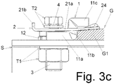
Figure 3c represents a plan view with the flange of the invention in adaptation phase. -
Figure 3d represents a plan view with the flange of the invention in final phase. -
Figure 4a represents a view in perspective of the flange which is the object of the invention, similar tofigure 2a , for an alternative embodiment. -
Figure 4b represents a view in perspective of the flange which is the object of the invention, similar tofigure 2b , for an alternative embodiment. -
Figure 5a represents a view in perspective of the screws (3), (4) for an alternative embodiment. -
Figure 5b represents a view in perspective of the fastening assembly (1) for the alternative embodiment of the screws (3), (4) represented infigure 5a . -
Figure 5c represents a plan view similar tofigure 3d , for the alternative embodiment that uses the fastening assembly (1) and the screws (3), (4) offigures 5a and5b . -
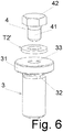
Figure 6 represents a view in perspective for an alternative embodiment in which the screws (3), (4) are two independent pieces. - The following describes an example of practical, non-limiting embodiment of this invention. Other modes of embodiment in which accessory changes which do not essentially change it are introduced are in no way disregarded.
- The object of the invention is a flange adjustable to the thickness of the wing of a lift guide. There is a flange for each wing (G1) of the lift guide (G), said guide resting (G) on a support (S) with orifices (S1) on which the assembly is fastened using a tightened screw (3) using a nut/washer set (T1).
- According to the invention, the flange consists of:
- a fastening assembly (1)
- An adjuster assembly (2);
- a screw (3) which is mounted without turning on the fastening assembly (1) or on the support (S) to fasten them to each other using a nut/washer set (T1);
- a fastening element (4) that together with the mentioned screw (3), first allows the movement of the adjuster assembly (2) in the fastening assembly (1); and then fastens the adjuster assembly (2) and the fastening assembly (1) to each other; and
- The fastening assembly (1) and the adjuster assembly (2) are arranged fastening the wing (G1) of the guide (G) between them and the support itself (S).
- The adjuster assembly (2) can move linearly guided in the fastening assembly (1) to adapt to the wings (G1) of different thicknesses.
- According to the embodiment represented in
figures 1 to 3 , the mentioned fastening assembly (1) consists of a single piece of sheet metal folded in "Z" shape that defines a core (11b) and two wings (11a), (11c). - One of these wings (11a) has a polygonal orifice (10) to house without turning a screw (3) and rests on the support (S). It also has pins (12) slightly inclined with respect to the plane of said wing (11a).
- The core (11b) stops against the edge of the corresponding wing (G1) of the guide (G).
- The other wing (11c) rests on the adjuster assembly (2).
- According to the embodiment represented in
figures 1 to 3 , the mentioned adjuster assembly (2) consists of a single piece of sheet metal folded, the "L" shape whose smaller wing (21b) consists of a handle to facilitate guided movement and whose larger wing (21a) has a long orifice (22) and a window (23). - In the smaller wing (21b) there is also at least a ridge (24) at its end zone; said ridge running (24) oriented toward the same side as the smaller wing (21b).
- According to embodiment represented in
figures 1 to 3 , there are means (12) to generate a force between the fastening assembly (1) and the support (S) that counteracts and reduces the frontal friction between the fastening assembly (1) and the wing (G1). In the embodiment represented, said means are pins (12) slightly inclined with respect to the plane of the wing (11a) of the fastening assembly (1) where they are located. - According to the embodiment represented in
figures 4a and4b , the mentioned fastening assembly (1) consists of a single piece of sheet metal folded in "Z" shape that defines a core (11b) and two wings (11a), (11c). - One of these wings (11a) has a polygonal orifice (10) to house without turning the screw (3) and rests on the support (S).
- The core (11b) defines a window (13) to house the adjuster assembly (2) and stops against the edge of the corresponding wing (G1) of the guide (G).
- The other wing (11c) rests on the adjuster assembly (2).
- The fastening assembly (1) and the support (S) are fastened to each other using the nut/washer (T1).
- According to the embodiment represented in
figures 4a and4b , the mentioned adjuster assembly (2) consists of a single piece of sheet metal folded, the "L" shape whose smaller wing (21b) consists of a handle to facilitate guided movement and whose larger wing (21a) has a long orifice (22). - In the smaller wing (21b) there is also at least one ridge (24) in its end zone; said ridge (24) being oriented toward the same side as the smaller wing (21b).
- In any of the embodiments, the mentioned screw (3) defines under its head (31) a portion (32) of polygonal geometry; and the fastening element (4) is extended axially with respect to the screw (3).
- It makes no difference for the purposes of the invention:
- that the screw (3) and the fastening element (4) are formed from the same base-piece, as in
figures 2b ,4b and5a ; or - that they are two independent pieces, assembled to each other; for example, that the screw (3) defines a threaded orifice (33) in which the fastening element (4) is placed, which is a commercial screw with its own head (42), that houses its threaded zone (41) in the threaded orifice (33) with interposition of washer (T2'), as in
figure 6 . - a) in pre-assembly phase (see
figure 3a ):- the adjuster assembly (2) is guided in the fastening assembly (1). The fastening element (4) is housed in the long orifice (22) of the adjuster assembly (2) which is left with clearance with respect to the fastening assembly (1) while the nut/washer set (T2) is loose;
- the fastening assembly (1) and the adjuster assembly (2) are arranged on the support (S) for which the screw (3) is housed in the orifice (S1) the wing (G1) of the guide (G) remaining clamped between them and the support (S) with clearance while nut/washer set (T1) is loose;
- the wing (11a) of the fastening assembly (1) is left with its pins (12) resting on the support (S) and with its core (11b) stopping against the wing (G1) of the guide (G); the wing (11c) of the fastening assembly (1) is left resting on the wing (21a) of the adjuster assembly (2) and it rests on the wing (G1) of the guide (G).
- b) in approach phase (see
figure 3b ):- to fasten without turning on fastening assembly (1) the support (S) the nut/washer set (T1) is tightened so that the pins (12) are deformed, generating a force between them and the support (S) that counteracts and reduces the frontal friction between the core (11b) and the edge of the guide (G1).
- c) in adaptation phase (see
figure 3c ):- the adjuster assembly (2) moves linearly pulling from its wing (21b) until the ridge or ridges (24) fit between the wing (G1) of the guide (G) and the wing (11c) of the fastening assembly (1). The movement will be different according to the thickness of the wing (G1); thus adapting the flange to wings (G1) of different thicknesses.
- d) in the final phase (see
figure 3d ):- the nut/washer set (T2) is tightened, fastening the adjuster assembly (2) to the rest of the flange.
- In any of the embodiments, the flange which is the object of the invention is fastened without turning with respect to the support (S). The specific way in which said fastening without turning is achieved makes no difference for the purposes of the invention. Thus:
- in the example of the embodiment of the
figures 2b and4b , the portion (32) defined under the head (31) of the screw (3) is housed in the polygonal orifice (10) defined in the wing (11a) of the piece of sheet metal that constitutes the fastening assembly (1). - in the example of embodiment of the
figures 5a and5b , the portion (32) defined under the head (31) of the screw (3) is of greater height; the orifice (10') defined in the wing (11a) of the piece of sheet metal that constitutes the fastening assembly (1) is circular while the orifice (S1') defined in the support (S) is always long. The fastening without turning takes place housing the portion (32) of the screw (3) in the orifice (S1') of the support (S) so that two opposite sides of said orifice (S1) accompany two opposite sides of the portion (32). Seefigure 5c . - The materials, dimensions, proportions and, in general, those other accessory or secondary details that do not essentially alter, change or modify the proposal may vary.
- The terms in which this report is written are a true and faithful reflection of the object described, and must be taken in their broadest sense and never in a limiting manner.
Claims (12)
- A flange, adjustable to the thickness of the wing of a lift guide; of the type that have a flange for each wing (G1) of the lift guide (G), said guide (G) resting on a support (S) that that has orifices (S1) in which the assembly is fastened; characterized in that it consists of:a) a fastening assembly (1) and an adjuster assembly (2) arranged fastening to each other and the support (S) to the wing (G1) of the guide (G); the adjuster assembly (2) being subject to guided linear movement with respect to the fastening assembly (1) to adapt to wings (G1) of different thicknesses; the fastening assembly (1) and the wing (G1) being stopped against each other, with frontal friction;b) a screw (3) that mounts without turning on the fastening assembly (1) or on the support (S) to fasten them to each other; andc) a fastening element (4) that joined to the screw (3) first allows the movement of the adjuster assembly (2) in the fastening assembly (1); and then to fasten between them the adjuster assembly (2) and the fastening assembly (1).
- A flange, according to claim 1, characterized in that the mentioned fastening assembly (1) consists of a single piece of sheet metal folded in "Z" shape, one of whose wings (11c) rests on the adjuster assembly (2) while the other wing (11a) has a polygonal orifice (10) to house, without turning, the screw (3) and rests on the support (S) while the core (11b) stops against the edge of the corresponding wing (G1) of the guide (G).
- A flange, according to claim 2, characterized in that the mentioned adjuster assembly (2) consists of a single piece of sheet metal folded, the "L" shape whose smaller wing (21b) consists of a handle to facilitate the guided movement and whose larger wing (21a) has a long orifice (22) to house the fastening element (4) and a window (23) to house the fastening assembly (1); having at least one ridge (23) in its end zone to adapt to wings (G1) of different thicknesses.
- A flange, according to claim 1, characterized in that it has means (12) to generate a force between the fastening assembly (1) and the support (S) that, on fastening them to each other, counteracts and reduces the frontal friction between the fastening assembly (1) and the wing (G1).
- A flange, according to claim 4, characterized in that the mentioned means (12) are pins that emerge from said sheet metal and are slightly inclined with respect to the plane of said wing (11a); so that, on tightening a nut/washer (T1) in the screw (3) to fasten to each other the fastening assembly (1) and support (S), the core (11b) tends to separate from the edge of the wing (G1).
- A flange, according to claim 1, characterized in that the mentioned fastening assembly (1) consists of a single piece of sheet metal folded in "Z" shape, one of whose wings (11c) rests on the adjuster assembly (2) while the other wing (11a) has a polygonal orifice (10) to house without turning the screw (3) and rests on the support (S) while the core (11b) defines a window (13') to house the adjuster assembly (2) and stops against the edge of the corresponding wing (G1) of the guide (G).
- A flange, according to claim 6, characterized in that the mentioned adjuster assembly (2) consists of a single piece of sheet metal folded, the "L" shape whose smaller wing (21b) consists of a handle to facilitate the guided movement and whose larger wing (21a) has a long orifice (22) to house the fastening element (4); having at least one ridge (23) in its edge zone to adapt to wings (G1) of different thicknesses.
- A flange, according to one of the foregoing claims, characterized in that the wing (11a) of the piece of sheet metal has an orifice (10') and rests on the support (S) with a polygonal orifice (S1') to house without turning the screw (3).
- A flange, according to claim 2 ó 6, characterized in that the mentioned screw (3) defines under its head (31) a portion (32) of polygonal geometry that fits in the polygonal orifice (10) of the sheet metal where it is housed without turning.
- A flange, according to claim 8, characterized in that the mentioned screw (3) defines under its head (31) a portion (32) of polygonal geometry that fits in the polygonal orifice (S1') of the support (S) where it is housed without turning.
- A flange, according to one of the foregoing claims, characterized in that the screw (3) and the fastening element (4) are threaded portions formed from the same base-piece; having in them respective nut/washer sets (T1), (T2).
- A flange, according to one of the claims 1 to 10, characterized in that the screw (3) carries on its head (31) a threaded orifice (33) in which the fastening element (4) is placed, which is an independent screw; the fastening assembly (1) and the adjuster assembly (2) remaining pinned between their respective heads (31), (42).
Applications Claiming Priority (1)
| Application Number | Priority Date | Filing Date | Title |
|---|---|---|---|
| ES201830372A ES2727504B2 (en) | 2018-04-16 | 2018-04-16 | Flange adjustable to the thickness of the flange of an elevator guide |
Publications (3)
| Publication Number | Publication Date |
|---|---|
| EP3556706A1 true EP3556706A1 (en) | 2019-10-23 |
| EP3556706B1 EP3556706B1 (en) | 2024-11-27 |
| EP3556706C0 EP3556706C0 (en) | 2024-11-27 |
Family
ID=64665080
Family Applications (1)
| Application Number | Title | Priority Date | Filing Date |
|---|---|---|---|
| EP18382860.7A Active EP3556706B1 (en) | 2018-04-16 | 2018-11-28 | Bracket assembly adjustable to the thickness of the wing of a lift guide |
Country Status (3)
| Country | Link |
|---|---|
| EP (1) | EP3556706B1 (en) |
| CN (1) | CN110388376B (en) |
| ES (1) | ES2727504B2 (en) |
Cited By (1)
| Publication number | Priority date | Publication date | Assignee | Title |
|---|---|---|---|---|
| US11136218B2 (en) * | 2017-03-28 | 2021-10-05 | Inventio Ag | Method for fastening a rail of an elevator system in an elevator shaft |
Families Citing this family (1)
| Publication number | Priority date | Publication date | Assignee | Title |
|---|---|---|---|---|
| CN111196541A (en) * | 2020-03-18 | 2020-05-26 | 迅达(中国)电梯有限公司 | Elevator guide rail fixing device |
Citations (3)
| Publication number | Priority date | Publication date | Assignee | Title |
|---|---|---|---|---|
| ES2557505A1 (en) * | 2014-07-24 | 2016-01-26 | S.A. De Vera (Savera) | Adaptable flange for elevator guides (Machine-translation by Google Translate, not legally binding) |
| WO2017103017A1 (en) * | 2015-12-17 | 2017-06-22 | Inventio Ag | Fastening module for fastening elevator rails |
| EP3381856A1 (en) * | 2017-03-30 | 2018-10-03 | Inventio AG | Fastening set with at least one fastening element for fastening a rail of an elevator assembly in an elevator shaft |
Family Cites Families (10)
| Publication number | Priority date | Publication date | Assignee | Title |
|---|---|---|---|---|
| US3982692A (en) * | 1974-07-19 | 1976-09-28 | R. Stahl Aufzuege Gmbh | Clamping means for elevator guide rails and the like |
| US5135165A (en) * | 1991-05-08 | 1992-08-04 | Gantrex Limited | Device for aligning and clamping a rail |
| FR2739650B3 (en) * | 1995-10-09 | 1997-12-05 | Gergonne Ets | WASHER FOR HINGE HINGE AND HINGE |
| DE102005054461B4 (en) * | 2005-11-15 | 2010-10-14 | Daimler Ag | Device for the pivotable connection of at least two components and method for mounting the device |
| JP2012086960A (en) * | 2010-10-21 | 2012-05-10 | Mitsubishi Electric Building Techno Service Co Ltd | Fastening jig of guide rail clip for elevator |
| CN103851061B (en) * | 2012-12-07 | 2016-12-21 | 上海汽车集团股份有限公司 | There is the assembling device of sealing function |
| WO2016151635A1 (en) * | 2015-03-26 | 2016-09-29 | 三菱電機株式会社 | Elevator guiderail support device |
| EP3390261B1 (en) * | 2015-12-17 | 2020-04-22 | Inventio AG | Fixing devices for fixing elevator guides |
| EP3393955A1 (en) * | 2015-12-22 | 2018-10-31 | Inventio AG | Elevator guide rail attachment clip |
| CN105387035A (en) * | 2015-12-24 | 2016-03-09 | 陆爱平 | Rapid-assembly flange groove mechanism locking device |
-
2018
- 2018-04-16 ES ES201830372A patent/ES2727504B2/en active Active
- 2018-11-28 EP EP18382860.7A patent/EP3556706B1/en active Active
- 2018-12-18 CN CN201811545964.9A patent/CN110388376B/en active Active
Patent Citations (3)
| Publication number | Priority date | Publication date | Assignee | Title |
|---|---|---|---|---|
| ES2557505A1 (en) * | 2014-07-24 | 2016-01-26 | S.A. De Vera (Savera) | Adaptable flange for elevator guides (Machine-translation by Google Translate, not legally binding) |
| WO2017103017A1 (en) * | 2015-12-17 | 2017-06-22 | Inventio Ag | Fastening module for fastening elevator rails |
| EP3381856A1 (en) * | 2017-03-30 | 2018-10-03 | Inventio AG | Fastening set with at least one fastening element for fastening a rail of an elevator assembly in an elevator shaft |
Cited By (1)
| Publication number | Priority date | Publication date | Assignee | Title |
|---|---|---|---|---|
| US11136218B2 (en) * | 2017-03-28 | 2021-10-05 | Inventio Ag | Method for fastening a rail of an elevator system in an elevator shaft |
Also Published As
| Publication number | Publication date |
|---|---|
| EP3556706B1 (en) | 2024-11-27 |
| ES2727504A1 (en) | 2019-10-16 |
| CN110388376A (en) | 2019-10-29 |
| ES2727504B2 (en) | 2020-10-16 |
| CN110388376B (en) | 2022-12-09 |
| EP3556706C0 (en) | 2024-11-27 |
Similar Documents
| Publication | Publication Date | Title |
|---|---|---|
| US10473142B2 (en) | Tolerance compensation apparatus | |
| EP3556706A1 (en) | Flange adjustable to the thickness of the wing of a lift guide | |
| CA3006977C (en) | Cable tray hold-down clamp | |
| US20140061412A1 (en) | Bracket with nut | |
| US9833813B2 (en) | Ultrasonic motor | |
| US20120133164A1 (en) | Adjustment flange for lift guides | |
| US11466739B2 (en) | Brake calliper arrangement having lining restoring function | |
| JP5984661B2 (en) | Guide rail support device for elevator | |
| US10047783B2 (en) | Flex reduction clip nut | |
| US20060214073A1 (en) | Fabricated heavy duty structural clamp | |
| JP5632941B1 (en) | Fastener mounting device and fastener mounting structure | |
| EP2936660B1 (en) | Electric motor with fan cowl and sensor | |
| CA2872892A1 (en) | Body | |
| CA2876491A1 (en) | Cartridge for a cutting insert | |
| JP6096429B2 (en) | Floating nut and floating bolt | |
| EP3245411B1 (en) | Locking device in a compensation nut | |
| US2760540A (en) | Headed screw fastener and resilient sheet metal retainer therefor | |
| US2630605A (en) | Door adjusting mechanism | |
| US2340250A (en) | Rotary stud fastener installation | |
| US20130343817A1 (en) | Clamping device | |
| US20210088071A1 (en) | Nut | |
| CA2475635C (en) | Pressing unit for separating the diecut blanks of a sheet | |
| EP2850971A1 (en) | Perfected hanging-bracket | |
| JP2016098890A (en) | Panel fixing structure, panel fixing metal fitting, rotary metal fitting and top plate metal fitting | |
| US20210148482A1 (en) | Securing Device for Attaching to a Ledge of an Actuating Drive Housing |
Legal Events
| Date | Code | Title | Description |
|---|---|---|---|
| PUAI | Public reference made under article 153(3) epc to a published international application that has entered the european phase |
Free format text: ORIGINAL CODE: 0009012 |
|
| STAA | Information on the status of an ep patent application or granted ep patent |
Free format text: STATUS: THE APPLICATION HAS BEEN PUBLISHED |
|
| AK | Designated contracting states |
Kind code of ref document: A1 Designated state(s): AL AT BE BG CH CY CZ DE DK EE ES FI FR GB GR HR HU IE IS IT LI LT LU LV MC MK MT NL NO PL PT RO RS SE SI SK SM TR |
|
| AX | Request for extension of the european patent |
Extension state: BA ME |
|
| STAA | Information on the status of an ep patent application or granted ep patent |
Free format text: STATUS: REQUEST FOR EXAMINATION WAS MADE |
|
| 17P | Request for examination filed |
Effective date: 20200423 |
|
| RBV | Designated contracting states (corrected) |
Designated state(s): AL AT BE BG CH CY CZ DE DK EE ES FI FR GB GR HR HU IE IS IT LI LT LU LV MC MK MT NL NO PL PT RO RS SE SI SK SM TR |
|
| STAA | Information on the status of an ep patent application or granted ep patent |
Free format text: STATUS: EXAMINATION IS IN PROGRESS |
|
| 17Q | First examination report despatched |
Effective date: 20210325 |
|
| GRAP | Despatch of communication of intention to grant a patent |
Free format text: ORIGINAL CODE: EPIDOSNIGR1 |
|
| STAA | Information on the status of an ep patent application or granted ep patent |
Free format text: STATUS: GRANT OF PATENT IS INTENDED |
|
| INTG | Intention to grant announced |
Effective date: 20240708 |
|
| GRAS | Grant fee paid |
Free format text: ORIGINAL CODE: EPIDOSNIGR3 |
|
| GRAA | (expected) grant |
Free format text: ORIGINAL CODE: 0009210 |
|
| STAA | Information on the status of an ep patent application or granted ep patent |
Free format text: STATUS: THE PATENT HAS BEEN GRANTED |
|
| AK | Designated contracting states |
Kind code of ref document: B1 Designated state(s): AL AT BE BG CH CY CZ DE DK EE ES FI FR GB GR HR HU IE IS IT LI LT LU LV MC MK MT NL NO PL PT RO RS SE SI SK SM TR |
|
| REG | Reference to a national code |
Ref country code: GB Ref legal event code: FG4D |
|
| REG | Reference to a national code |
Ref country code: CH Ref legal event code: EP |
|
| REG | Reference to a national code |
Ref country code: DE Ref legal event code: R096 Ref document number: 602018076921 Country of ref document: DE |
|
| REG | Reference to a national code |
Ref country code: IE Ref legal event code: FG4D |
|
| U01 | Request for unitary effect filed |
Effective date: 20241219 |
|
| U07 | Unitary effect registered |
Designated state(s): AT BE BG DE DK EE FI FR IT LT LU LV MT NL PT RO SE SI Effective date: 20250207 |
|
| U1N | Appointed representative for the unitary patent procedure changed after the registration of the unitary effect |
Representative=s name: PEREIRA DA CRUZ, JOAO; PT |
|
| U20 | Renewal fee for the european patent with unitary effect paid |
Year of fee payment: 7 Effective date: 20250221 |
|
| PG25 | Lapsed in a contracting state [announced via postgrant information from national office to epo] |
Ref country code: IS Free format text: LAPSE BECAUSE OF FAILURE TO SUBMIT A TRANSLATION OF THE DESCRIPTION OR TO PAY THE FEE WITHIN THE PRESCRIBED TIME-LIMIT Effective date: 20250327 Ref country code: HR Free format text: LAPSE BECAUSE OF FAILURE TO SUBMIT A TRANSLATION OF THE DESCRIPTION OR TO PAY THE FEE WITHIN THE PRESCRIBED TIME-LIMIT Effective date: 20241127 |
|
| PG25 | Lapsed in a contracting state [announced via postgrant information from national office to epo] |
Ref country code: ES Free format text: LAPSE BECAUSE OF FAILURE TO SUBMIT A TRANSLATION OF THE DESCRIPTION OR TO PAY THE FEE WITHIN THE PRESCRIBED TIME-LIMIT Effective date: 20241127 |
|
| PG25 | Lapsed in a contracting state [announced via postgrant information from national office to epo] |
Ref country code: NO Free format text: LAPSE BECAUSE OF FAILURE TO SUBMIT A TRANSLATION OF THE DESCRIPTION OR TO PAY THE FEE WITHIN THE PRESCRIBED TIME-LIMIT Effective date: 20250227 |
|
| PG25 | Lapsed in a contracting state [announced via postgrant information from national office to epo] |
Ref country code: GR Free format text: LAPSE BECAUSE OF FAILURE TO SUBMIT A TRANSLATION OF THE DESCRIPTION OR TO PAY THE FEE WITHIN THE PRESCRIBED TIME-LIMIT Effective date: 20250228 |
|
| PG25 | Lapsed in a contracting state [announced via postgrant information from national office to epo] |
Ref country code: PL Free format text: LAPSE BECAUSE OF FAILURE TO SUBMIT A TRANSLATION OF THE DESCRIPTION OR TO PAY THE FEE WITHIN THE PRESCRIBED TIME-LIMIT Effective date: 20241127 |
|
| PG25 | Lapsed in a contracting state [announced via postgrant information from national office to epo] |
Ref country code: RS Free format text: LAPSE BECAUSE OF FAILURE TO SUBMIT A TRANSLATION OF THE DESCRIPTION OR TO PAY THE FEE WITHIN THE PRESCRIBED TIME-LIMIT Effective date: 20250227 |
|
| REG | Reference to a national code |
Ref country code: CH Ref legal event code: PL |
|
| PG25 | Lapsed in a contracting state [announced via postgrant information from national office to epo] |
Ref country code: SM Free format text: LAPSE BECAUSE OF FAILURE TO SUBMIT A TRANSLATION OF THE DESCRIPTION OR TO PAY THE FEE WITHIN THE PRESCRIBED TIME-LIMIT Effective date: 20241127 |
|
| REG | Reference to a national code |
Ref country code: CH Ref legal event code: PL |
|
| PG25 | Lapsed in a contracting state [announced via postgrant information from national office to epo] |
Ref country code: CH Free format text: LAPSE BECAUSE OF NON-PAYMENT OF DUE FEES Effective date: 20241130 |
|
| PG25 | Lapsed in a contracting state [announced via postgrant information from national office to epo] |
Ref country code: SK Free format text: LAPSE BECAUSE OF FAILURE TO SUBMIT A TRANSLATION OF THE DESCRIPTION OR TO PAY THE FEE WITHIN THE PRESCRIBED TIME-LIMIT Effective date: 20241127 |
|
| PG25 | Lapsed in a contracting state [announced via postgrant information from national office to epo] |
Ref country code: CZ Free format text: LAPSE BECAUSE OF FAILURE TO SUBMIT A TRANSLATION OF THE DESCRIPTION OR TO PAY THE FEE WITHIN THE PRESCRIBED TIME-LIMIT Effective date: 20241127 |
|
| PG25 | Lapsed in a contracting state [announced via postgrant information from national office to epo] |
Ref country code: MC Free format text: LAPSE BECAUSE OF FAILURE TO SUBMIT A TRANSLATION OF THE DESCRIPTION OR TO PAY THE FEE WITHIN THE PRESCRIBED TIME-LIMIT Effective date: 20241127 |
|
| PLBE | No opposition filed within time limit |
Free format text: ORIGINAL CODE: 0009261 |
|
| STAA | Information on the status of an ep patent application or granted ep patent |
Free format text: STATUS: NO OPPOSITION FILED WITHIN TIME LIMIT |
|
| PG25 | Lapsed in a contracting state [announced via postgrant information from national office to epo] |
Ref country code: IE Free format text: LAPSE BECAUSE OF NON-PAYMENT OF DUE FEES Effective date: 20241128 |
|
| GBPC | Gb: european patent ceased through non-payment of renewal fee |
Effective date: 20250227 |
|
| 26N | No opposition filed |
Effective date: 20250828 |
|
| U20 | Renewal fee for the european patent with unitary effect paid |
Year of fee payment: 8 Effective date: 20251023 |
|
| PG25 | Lapsed in a contracting state [announced via postgrant information from national office to epo] |
Ref country code: GB Free format text: LAPSE BECAUSE OF NON-PAYMENT OF DUE FEES Effective date: 20250227 |
|
| PG25 | Lapsed in a contracting state [announced via postgrant information from national office to epo] |
Ref country code: HU Free format text: LAPSE BECAUSE OF FAILURE TO SUBMIT A TRANSLATION OF THE DESCRIPTION OR TO PAY THE FEE WITHIN THE PRESCRIBED TIME-LIMIT; INVALID AB INITIO Effective date: 20181128 |
|
| PG25 | Lapsed in a contracting state [announced via postgrant information from national office to epo] |
Ref country code: CY Free format text: LAPSE BECAUSE OF FAILURE TO SUBMIT A TRANSLATION OF THE DESCRIPTION OR TO PAY THE FEE WITHIN THE PRESCRIBED TIME-LIMIT; INVALID AB INITIO Effective date: 20181128 |