EP3556702A1 - Augmented reality car operating panel - Google Patents
Augmented reality car operating panel Download PDFInfo
- Publication number
- EP3556702A1 EP3556702A1 EP19162375.0A EP19162375A EP3556702A1 EP 3556702 A1 EP3556702 A1 EP 3556702A1 EP 19162375 A EP19162375 A EP 19162375A EP 3556702 A1 EP3556702 A1 EP 3556702A1
- Authority
- EP
- European Patent Office
- Prior art keywords
- car
- elevator
- passenger
- operating panel
- virtual element
- Prior art date
- Legal status (The legal status is an assumption and is not a legal conclusion. Google has not performed a legal analysis and makes no representation as to the accuracy of the status listed.)
- Pending
Links
Images


Classifications
-
- B—PERFORMING OPERATIONS; TRANSPORTING
- B66—HOISTING; LIFTING; HAULING
- B66B—ELEVATORS; ESCALATORS OR MOVING WALKWAYS
- B66B1/00—Control systems of elevators in general
- B66B1/34—Details, e.g. call counting devices, data transmission from car to control system, devices giving information to the control system
- B66B1/46—Adaptations of switches or switchgear
- B66B1/52—Floor selectors
-
- B—PERFORMING OPERATIONS; TRANSPORTING
- B66—HOISTING; LIFTING; HAULING
- B66B—ELEVATORS; ESCALATORS OR MOVING WALKWAYS
- B66B1/00—Control systems of elevators in general
- B66B1/34—Details, e.g. call counting devices, data transmission from car to control system, devices giving information to the control system
- B66B1/46—Adaptations of switches or switchgear
- B66B1/461—Adaptations of switches or switchgear characterised by their shape or profile
-
- B—PERFORMING OPERATIONS; TRANSPORTING
- B66—HOISTING; LIFTING; HAULING
- B66B—ELEVATORS; ESCALATORS OR MOVING WALKWAYS
- B66B1/00—Control systems of elevators in general
- B66B1/34—Details, e.g. call counting devices, data transmission from car to control system, devices giving information to the control system
- B66B1/46—Adaptations of switches or switchgear
- B66B1/467—Adaptations of switches or switchgear characterised by their mounting position
-
- B—PERFORMING OPERATIONS; TRANSPORTING
- B66—HOISTING; LIFTING; HAULING
- B66B—ELEVATORS; ESCALATORS OR MOVING WALKWAYS
- B66B1/00—Control systems of elevators in general
- B66B1/34—Details, e.g. call counting devices, data transmission from car to control system, devices giving information to the control system
- B66B1/46—Adaptations of switches or switchgear
- B66B1/468—Call registering systems
-
- B—PERFORMING OPERATIONS; TRANSPORTING
- B66—HOISTING; LIFTING; HAULING
- B66B—ELEVATORS; ESCALATORS OR MOVING WALKWAYS
- B66B3/00—Applications of devices for indicating or signalling operating conditions of elevators
- B66B3/002—Indicators
- B66B3/008—Displaying information not related to the elevator, e.g. weather, publicity, internet or TV
-
- B—PERFORMING OPERATIONS; TRANSPORTING
- B66—HOISTING; LIFTING; HAULING
- B66B—ELEVATORS; ESCALATORS OR MOVING WALKWAYS
- B66B2201/00—Aspects of control systems of elevators
- B66B2201/40—Details of the change of control mode
- B66B2201/46—Switches or switchgear
- B66B2201/4607—Call registering systems
- B66B2201/4638—Wherein the call is registered without making physical contact with the elevator system
- B66B2201/4646—Wherein the call is registered without making physical contact with the elevator system using voice recognition
Definitions
- the subject matter disclosed herein generally relates to elevator systems and, more particularly, to an augmented reality car operating panel.
- Elevator systems typically include a car operating panel (COP) utilized for operation of the elevator car.
- the car operating panel receives elevator passenger inputs that can then designate a desired floor, hold open or close the elevator car doors, sound an alarm, and the like.
- Car operating panels utilizing buttons and touch based systems have a variety of issues that present themselves overtime such as, for example, wear and tear of buttons, loss of touch sensitivity over time, regular service and cleaning is required, cost ineffectiveness, reduced passenger experience, power consumption, and hygienic issues as physical touch is required.
- further embodiments of the elevator system may include that the action comprises initiating an elevator command for the elevator car.
- further embodiments of the elevator system may include that the action comprises adding, by the controller, a second virtual element to the car operating panel and projecting, by the projector, the second virtual element in the car operating panel.
- further embodiments of the elevator system may include that the activation of the virtual element from the passenger comprises engaging, by the passenger, a region in the virtual element for a duration of time.
- further embodiments of the elevator system may include that the activation of the virtual element from the passenger comprises engaging, by the passenger, a region in the virtual element utilizing a movement pattern.
- further embodiments of the elevator system may include that the virtual element comprises a first color and responsive to sensing the activation of the virtual element from the passenger, the virtual element changes to a second color.
- further embodiments of the elevator system may include that the controller is further configured to periodically detect, by the sensor, the presence of the passenger and responsive to the passenger exiting the elevator car, initiating a power savings mode for the car operating panel.
- further embodiments of the elevator system may include that the car operating panel is projected on to a surface of the elevator car.
- further embodiments of the elevator system may include that the car operating panel comprises a first mode and a second mode and wherein the first mode comprises a minimal display of the virtual element and wherein the second mode comprises a descriptive display of the virtual element.
- further embodiments of the elevator system may include that the initiating the action comprises projecting, by the projector, the second mode for the car operating panel.
- further embodiments of the elevator system may include that the controller is further operable to determine a location of the passenger in the elevator car and the car operating panel is projected to a second location proximate to the location of the passenger.
- further embodiments of the elevator system may include that the car operating panel further comprises a news feed.
- further embodiments of the elevator system may include a microphone, the microphone is operated by the controller and the controller is further configured to receive an audio command from the user and responsive to the audio command from the user, initiate a second action for the elevator car.
- a computer-implemented method for operating an elevator system includes receiving an indication of a presence of a passenger in an elevator car.
- a car operating panel is projected, by a projector in the elevator car and the car operating panel comprises a virtual element.
- An activation of the virtual element from the passenger is sensed by a sensor and an action is initiated based at least in part on sensing the activation of the virtual element.
- further embodiments of the method may include that initiating the action comprises initiating an elevator command for the elevator car.
- further embodiments of the method may include that initiating the action comprises adding a second virtual element to the car operating panel and projecting, by the projector, the second virtual element in the car operating panel.
- further embodiments of the method may include that the activation of the virtual element from the passenger comprises engaging, by the passenger, a region in the virtual element for a duration of time.
- further embodiments of the method may include that the activation of the virtual element from the passenger comprises engaging, by the passenger, a region in the virtual element utilizing a movement pattern.
- further embodiments of the method may include that the virtual element comprises a first color and responsive to sensing the activation of the virtual element from the passenger, the virtual element changes to a second color.
- further embodiments of the method may include periodically detecting, by the sensor, the presence of the passenger and responsive to the passenger exiting the elevator car, initiating a power savings mode for the car operating panel.
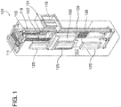
- FIG. 1 is a perspective view of an elevator system 101 including an elevator car 103, a counterweight 105, a roping 107, a guide rail 109, a machine 111, a position encoder 113, and a controller 115.
- the elevator car 103 and counterweight 105 are connected to each other by the roping 107.
- the roping 107 may include or be configured as, for example, ropes, steel cables, and/or coated-steel belts.
- the counterweight 105 is configured to balance a load of the elevator car 103 and is configured to facilitate movement of the elevator car 103 concurrently and in an opposite direction with respect to the counterweight 105 within an elevator shaft 117 and along the guide rail 109.
- the roping 107 engages the machine 111, which is part of an overhead structure of the elevator system 101.
- the machine 111 is configured to control movement of the elevator car 103 and the counterweight 105.
- the position encoder 113 may be mounted on an upper sheave of a speed-governor system 119 and may be configured to provide position signals related to a position of the elevator car 103 within the elevator shaft 117. In other embodiments, the position encoder 113 may be directly mounted to a moving component of the machine 111, or may be located in other positions and/or configurations as known in the art.
- the controller 115 is located, as shown, in a controller room 121 of the elevator shaft 117 and is configured to control the operation of the elevator system 101, and particularly the elevator car 103.
- the controller 115 may provide drive signals to the machine 111 to control the acceleration, deceleration, leveling, stopping, etc. of the elevator car 103.
- the controller 115 may also be configured to receive position signals from the position encoder 113.
- the elevator car 103 may stop at one or more landings 125 as controlled by the controller 115.
- the controller 115 can be located and/or configured in other locations or positions within the elevator system 101.
- the machine 111 may include a motor or similar driving mechanism.
- the machine 111 is configured to include an electrically driven motor.
- the power supply for the motor may be any power source, including a power grid, which, in combination with other components, is supplied to the motor.
- FIG. 1 is merely a non-limiting example presented for illustrative and explanatory purposes.
- processors 21a, 21b, 21c, etc. collectively or generically referred to as processor(s) 21.
- processors 21 may include a reduced instruction set computer (RISC) microprocessor.
- RISC reduced instruction set computer
- processors 21 are coupled to system memory 34 (RAM) and various other components via a system bus 33.
- RAM system memory
- ROM Read only memory
- BIOS basic input/output system
- FIG. 2 further depicts an input/output (I/O) adapter 27 and a network adapter 26 coupled to the system bus 33.
- I/O adapter 27 may be a small computer system interface (SCSI) adapter that communicates with a hard disk 23 and/or tape storage drive 25 or any other similar component.
- I/O adapter 27, hard disk 23, and tape storage device 25 are collectively referred to herein as mass storage 24.
- Operating system 40 for execution on the processing system 200 may be stored in mass storage 24.
- a network communications adapter 26 interconnects bus 33 with an outside network 36 enabling data processing system 200 to communicate with other such systems.
- a screen (e.g., a display monitor) 35 is connected to system bus 33 by display adaptor 32, which may include a graphics adapter to improve the performance of graphics intensive applications and a video controller.
- adapters 27, 26, and 32 may be connected to one or more I/O busses that are connected to system bus 33 via an intermediate bus bridge (not shown).
- Suitable I/O buses for connecting peripheral devices such as hard disk controllers, network adapters, and graphics adapters typically include common protocols, such as the Peripheral Component Interconnect (PCI).
- PCI Peripheral Component Interconnect
- Additional input/output devices are shown as connected to system bus 33 via user interface adapter 28 and display adapter 32.
- a keyboard 29, mouse 30, and speaker 31 all interconnected to bus 33 via user interface adapter 28, which may include, for example, a Super I/O chip integrating multiple device adapters into a single integrated circuit.
- the processing system 200 includes a graphics processing unit 41.
- Graphics processing unit 41 is a specialized electronic circuit designed to manipulate and alter memory to accelerate the creation of images in a frame buffer intended for output to a display.
- Graphics processing unit 41 is very efficient at manipulating computer graphics and image processing and has a highly parallel structure that makes it more effective than general-purpose CPUs for algorithms where processing of large blocks of data is done in parallel.
- the processing system 200 described herein is merely exemplary and not intended to limit the application, uses, and/or technical scope of the present disclosure, which can be embodied in various forms known in the art.
- the system 200 includes processing capability in the form of processors 21, storage capability including system memory 34 and mass storage 24, input means such as keyboard 29 and mouse 30, and output capability including speaker 31 and display 35.
- processing capability in the form of processors 21, storage capability including system memory 34 and mass storage 24, input means such as keyboard 29 and mouse 30, and output capability including speaker 31 and display 35.
- a portion of system memory 34 and mass storage 24 collectively store an operating system coordinate the functions of the various components shown in FIG. 2.
- FIG. 2 is merely a non-limiting example presented for illustrative and explanatory purposes.
- one or more embodiments address the above-described shortcomings of the prior art by providing an elevator system that utilizes augmented reality for the functionality of a car operating panel utilizing three-dimensional (3D) holography.
- Aspects include a holographic projection device in electronic communication with an elevator controller to receive a passenger input in an elevator car.
- the holographic projection device can project the car operating panel onto a surface within the elevator car or it can project the COP into the air within the elevator car.
- a passenger can select a floor by inputting a command into the holographic COP which is then communicated to the elevator controller.
- FIG. 3 depicts a system 300 for an augmented reality car operating panel in an elevator.
- the system 300 includes an elevator car 304.
- the system 300 also includes a controller 302, a network 320, a database 322, and a user device 324.
- the elevator car 304 includes at least one projector 306, a voice sensor 308, a camera 310, and a sensor 312.
- the elevator car 304 also includes at least one car operating panel 314.
- the controller 302 can be implemented on the processing system 200 found in FIG. 2 .
- a cloud computing system can be in wired or wireless electronic communication with one or all of the elements of the system 300. Cloud computing can supplement, support or replace some or all of the functionality of the elements of the system 300. Additionally, some or all of the functionality of the elements of system 300 can be implemented as a node of a cloud computing system.
- a cloud computing node is only one example of a suitable cloud computing node and is not intended to suggest any limitation as to the scope of use or functionality of embodiments described herein.
- the COP 314 can be projected onto a surface within the elevator car 304 or the COP 314 can be projected in the air within the elevator car 304.
- the COP 314 can include one or more virtual elements within the projected COP.
- the one or more virtual elements can include virtual representations of elevator buttons, display screens, video, images, or other virtual media such as news feeds and the like.
- the virtual elements on the car operating panel 304 can be activated to engage the elevator car 304.
- a passenger enters the elevator car and the projector 306 projects the car operating panel 314 in the elevator car 304 with virtual elevator buttons.
- the passenger can press at the virtual elevator buttons which causes the controller 302 to activate the elevator car 304 and deliver the passenger to a desired floor.
- the passenger can move his or her finger to a location 406 on the virtual element 406.
- the user's finger is found to be at or around the location 406 on the '6' button (e.g., virtual element) which corresponds to an elevator call to the sixth floor of a building.
- a virtual element 402 when a virtual element 402 is activated by a passenger, it can change colors, size, shape, or shading to indicate that the selection has been received or acknowledged by the car operating panel 314.
- a passenger's hand might be at more than one location.
- the index finger of the passenger is at the first location 406 and also the passenger's thumb is shown to be at a second location 408 which corresponds to the '9' button (e.g., virtual element).
- the camera 310 captures the media of the passenger's hand and transmits the media to the controller 302.
- the controller 302, utilizing logic, can determine a confidence interval for the first location 406 and the second location 408 to determine which location (region in the virtual element) is being selected by the passenger.
- the locations with the highest confidence interval can be chosen as the virtual element being selected by the passenger.
- the '6' button is the button being selected.
- the car operating panel 314 can alert the passenger to adjust their selection by moving their hand or finger to a region more indicative of their selection.
- the alert could be in the form of a message text on the car operating panel 314 or the car operating panel 314 projection can be augmented in size, shape, color, or shading to alert the passenger to make another selection.
- any type of sensor 312 can be utilized to detect a passenger's selection of a virtual element 402.
- the car operating penal 314 can operate in several modes such as a first mode that displays basic virtual elements 402 such as numbering or one or two word buttons as illustrated in FIG. 4 . Also, a second mode can be utilized that displays descriptive virtual elements.
- FIG. 5 depicts a car operating panel displaying descriptive virtual elements according to one or more embodiments. The car operating panel 314 is projected by a projector 306 with the camera 310 capturing media associated with the car operating panel 314. One or more virtual elements 502 are displayed in the car operating panel. In the illustrative example, the virtual elements 502 are descriptive indicating office tenants that can be accessed by an elevator car 304.
- FIGs. 4 and 5 are illustrative of car operating panels and are not meant to limit the scope of the car operating panels.
- a car operating panel 314 can display a variety of themes and virtual elements that match the themes.
- an elevator car at an aquarium can utilize a marine theme and the virtual elements could be in the shape and color of aquatic animals.
- a number of themes can be stored on the database 322 and accessed through the network 320 by the controller.
- the user device 324 can access the themes on the database 322 and adjust the themes for the car operating panel 314 in real time.
- Themes for the car operating panel 314 can be scheduled throughout a day, week, month or year for special holidays or events corresponding to the building events scheduled.
- the passenger can maneuver his or her hand to a region at or near the desired virtual element. As the passenger's hand is present at the region at the virtual element for a duration of time, the virtual element is activated and the controller 402 can receive a signal indicating to engage the elevator car 304.
- the passenger's hand or finger can utilize a movement pattern to activate the virtual element 402.
- the car operating panel 314 can display multiple virtual elements 402 and a passenger can move his or her finger through the virtual element as if pushing a physical representation of the virtual element. This finger movement through the virtual element (e.g., movement pattern) can be recognized by the controller 302 to indicate activation of the virtual element.
- the car operating panel 314 can include a doodle for the associated theme of the car operating panel 314.
- the doodle can change periodically (e.g., hourly, daily, etc.) to resemble a specialty of a particular day.
- the doodle can include a search feature that allows passengers to search for tenants in the building or other searchable features for the building or region.
- the voice sensor 308 can be utilized to assist passengers that are unable to utilize the car operating panel 314. For example, a blind passenger will not be able to see the projection and can utilize voice commands to activate the elevator commands.
- the projector 306 can project the car operating panel 314 on to a specific surface in the elevator car 304.
- the surface of the elevator car 304 can have braille engraved at regions that correspond to virtual elements of the car operating panel 314. This can assist blind passengers with activating the virtual elements to indicate a desired floor.
- the camera 310 can capture hand movements and gestures from passengers that may need assistance. Image processing techniques can be utilized for gesture recognition for passengers.
- the elevator car 304 can have a near field communication (NFC) transceiver affixed to it to communicate with the user device 324 that has a corresponding NFC transceiver.
- NFC near field communication
- the user device 324 can transmit signals to the controller 302 to indicate the passenger can access restricted floors and the projection of the car operating panel 314 can display virtual elements corresponding to the restricted floors for the passenger.
- the database 322 can store new themes and software updates that can be transmitted to the controller 302 to update the care operating panel 314 in the elevator car 304.
- the camera 310 utilizing image recognition techniques can determine physical features of a passenger to project the car operating panel 314 at a location that is convenient for the passenger. For example, passengers that are shorter might require the car operating panel 314 to be projected at a lower location in the elevator car 304 for ease of use.
- FIG. 6 depicts a flow diagram of a method for inspecting an elevator system according to one or more embodiments.
- the method 600 includes receiving an indication of a presence of a passenger in an elevator car, as shown at block 602.
- the method 600 includes projecting, by the projector, a car operating panel in the elevator car, wherein the car operating panel comprises a virtual element.
- the method 600 then includes sensing, by a sensor, an activation of the virtual element from the passenger, as shown at block 606.
- the method 600 includes initiating an action based at least in part on sensing the activation of the virtual element.
Abstract
Description
- The subject matter disclosed herein generally relates to elevator systems and, more particularly, to an augmented reality car operating panel.
- Elevator systems typically include a car operating panel (COP) utilized for operation of the elevator car. The car operating panel receives elevator passenger inputs that can then designate a desired floor, hold open or close the elevator car doors, sound an alarm, and the like. Car operating panels utilizing buttons and touch based systems have a variety of issues that present themselves overtime such as, for example, wear and tear of buttons, loss of touch sensitivity over time, regular service and cleaning is required, cost ineffectiveness, reduced passenger experience, power consumption, and hygienic issues as physical touch is required.
- According to one embodiment, an elevator system is provided. The elevator system includes an elevator car, a sensor, and a projector affixed to the elevator car, wherein the projector is operated by a controller and the controller is configured to receive an indication of a presence of a passenger in the elevator car. A car operating panel is projected, by a projector, in the elevator car, wherein the car operating panel comprises a virtual element. An activation of the virtual element from the passenger is sensed by a sensor and an action is initiated based at least in part on sensing the activation of the virtual element.
- In addition to one or more of the features described above, or as an alternative, further embodiments of the elevator system may include that the action comprises initiating an elevator command for the elevator car.
- In addition to one or more of the features described above, or as an alternative, further embodiments of the elevator system may include that the action comprises adding, by the controller, a second virtual element to the car operating panel and projecting, by the projector, the second virtual element in the car operating panel.
- In addition to one or more of the features described above, or as an alternative, further embodiments of the elevator system may include that the activation of the virtual element from the passenger comprises engaging, by the passenger, a region in the virtual element for a duration of time.
- In addition to one or more of the features described above, or as an alternative, further embodiments of the elevator system may include that the activation of the virtual element from the passenger comprises engaging, by the passenger, a region in the virtual element utilizing a movement pattern.
- In addition to one or more of the features described above, or as an alternative, further embodiments of the elevator system may include that the virtual element comprises a first color and responsive to sensing the activation of the virtual element from the passenger, the virtual element changes to a second color.
- In addition to one or more of the features described above, or as an alternative, further embodiments of the elevator system may include that the controller is further configured to periodically detect, by the sensor, the presence of the passenger and responsive to the passenger exiting the elevator car, initiating a power savings mode for the car operating panel.
- In addition to one or more of the features described above, or as an alternative, further embodiments of the elevator system may include that the car operating panel is projected on to a surface of the elevator car.
- In addition to one or more of the features described above, or as an alternative, further embodiments of the elevator system may include that the car operating panel comprises a first mode and a second mode and wherein the first mode comprises a minimal display of the virtual element and wherein the second mode comprises a descriptive display of the virtual element.
- In addition to one or more of the features described above, or as an alternative, further embodiments of the elevator system may include that the initiating the action comprises projecting, by the projector, the second mode for the car operating panel.
- In addition to one or more of the features described above, or as an alternative, further embodiments of the elevator system may include that the controller is further operable to determine a location of the passenger in the elevator car and the car operating panel is projected to a second location proximate to the location of the passenger.
- In addition to one or more of the features described above, or as an alternative, further embodiments of the elevator system may include that the car operating panel further comprises a news feed.
- In addition to one or more of the features described above, or as an alternative, further embodiments of the elevator system may include a microphone, the microphone is operated by the controller and the controller is further configured to receive an audio command from the user and responsive to the audio command from the user, initiate a second action for the elevator car.
- According to one embodiment, a computer-implemented method for operating an elevator system is provided. The method includes receiving an indication of a presence of a passenger in an elevator car. A car operating panel is projected, by a projector in the elevator car and the car operating panel comprises a virtual element. An activation of the virtual element from the passenger is sensed by a sensor and an action is initiated based at least in part on sensing the activation of the virtual element.
- In addition to one or more of the features described above, or as an alternative, further embodiments of the method may include that initiating the action comprises initiating an elevator command for the elevator car.
- In addition to one or more of the features described above, or as an alternative, further embodiments of the method may include that initiating the action comprises adding a second virtual element to the car operating panel and projecting, by the projector, the second virtual element in the car operating panel.
- In addition to one or more of the features described above, or as an alternative, further embodiments of the method may include that the activation of the virtual element from the passenger comprises engaging, by the passenger, a region in the virtual element for a duration of time.
- In addition to one or more of the features described above, or as an alternative, further embodiments of the method may include that the activation of the virtual element from the passenger comprises engaging, by the passenger, a region in the virtual element utilizing a movement pattern.
- In addition to one or more of the features described above, or as an alternative, further embodiments of the method may include that the virtual element comprises a first color and responsive to sensing the activation of the virtual element from the passenger, the virtual element changes to a second color.
- In addition to one or more of the features described above, or as an alternative, further embodiments of the method may include periodically detecting, by the sensor, the presence of the passenger and responsive to the passenger exiting the elevator car, initiating a power savings mode for the car operating panel.
- The present disclosure is illustrated by way of example and not limited in the accompanying figures in which like reference numerals indicate similar elements.
-
FIG. 1 is a schematic illustration of an elevator system that may employ various embodiments of the disclosure; -
FIG. 2 depicts a block diagram of a computer system for use in implementing one or more embodiments of the disclosure; -
FIG. 3 depicts a block diagram of a system for an augmented reality car operating panel in an elevator according to one or more embodiments of the disclosure; -
FIG 4 depicts a car operating panel according to one or more embodiments; -
FIG. 5 depicts a car operating panel displaying descriptive virtual elements according to one or more embodiments; and -
FIG. 6 depicts a flow diagram of a method for operating an elevator system according to one or more embodiments of the disclosure. - As shown and described herein, various features of the disclosure will be presented. Various embodiments may have the same or similar features and thus the same or similar features may be labeled with the same reference numeral, but preceded by a different first number indicating the figure to which the feature is shown. Thus, for example, element "a" that is shown in FIG. X may be labeled "Xa" and a similar feature in FIG. Z may be labeled "Za." Although similar reference numbers may be used in a generic sense, various embodiments will be described and various features may include changes, alterations, modifications, etc. as will be appreciated by those of skill in the art, whether explicitly described or otherwise would be appreciated by those of skill in the art.
-
FIG. 1 is a perspective view of anelevator system 101 including anelevator car 103, acounterweight 105, aroping 107, aguide rail 109, amachine 111, aposition encoder 113, and acontroller 115. Theelevator car 103 andcounterweight 105 are connected to each other by theroping 107. Theroping 107 may include or be configured as, for example, ropes, steel cables, and/or coated-steel belts. Thecounterweight 105 is configured to balance a load of theelevator car 103 and is configured to facilitate movement of theelevator car 103 concurrently and in an opposite direction with respect to thecounterweight 105 within anelevator shaft 117 and along theguide rail 109. - The
roping 107 engages themachine 111, which is part of an overhead structure of theelevator system 101. Themachine 111 is configured to control movement of theelevator car 103 and thecounterweight 105. Theposition encoder 113 may be mounted on an upper sheave of a speed-governor system 119 and may be configured to provide position signals related to a position of theelevator car 103 within theelevator shaft 117. In other embodiments, theposition encoder 113 may be directly mounted to a moving component of themachine 111, or may be located in other positions and/or configurations as known in the art. - The
controller 115 is located, as shown, in acontroller room 121 of theelevator shaft 117 and is configured to control the operation of theelevator system 101, and particularly theelevator car 103. For example, thecontroller 115 may provide drive signals to themachine 111 to control the acceleration, deceleration, leveling, stopping, etc. of theelevator car 103. Thecontroller 115 may also be configured to receive position signals from theposition encoder 113. When moving up or down within theelevator shaft 117 alongguide rail 109, theelevator car 103 may stop at one ormore landings 125 as controlled by thecontroller 115. Although shown in acontroller room 121, those of skill in the art will appreciate that thecontroller 115 can be located and/or configured in other locations or positions within theelevator system 101. - The
machine 111 may include a motor or similar driving mechanism. In accordance with embodiments of the disclosure, themachine 111 is configured to include an electrically driven motor. The power supply for the motor may be any power source, including a power grid, which, in combination with other components, is supplied to the motor. - Although shown and described with a roping system, elevator systems that employ other methods and mechanisms of moving an elevator car within an elevator shaft, such as hydraulic and/or ropeless elevators, may employ embodiments of the present disclosure.
FIG. 1 is merely a non-limiting example presented for illustrative and explanatory purposes. - Referring to
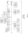
FIG. 2 , there is shown an embodiment of aprocessing system 200 for implementing the teachings herein. In this embodiment, thesystem 200 has one or more central processing units (processors) 21a, 21b, 21c, etc. (collectively or generically referred to as processor(s) 21). In one or more embodiments, each processor 21 may include a reduced instruction set computer (RISC) microprocessor. Processors 21 are coupled to system memory 34 (RAM) and various other components via a system bus 33. Read only memory (ROM) 22 is coupled to the system bus 33 and may include a basic input/output system (BIOS), which controls certain basic functions ofsystem 200. -
FIG. 2 further depicts an input/output (I/O)adapter 27 and anetwork adapter 26 coupled to the system bus 33. I/O adapter 27 may be a small computer system interface (SCSI) adapter that communicates with ahard disk 23 and/ortape storage drive 25 or any other similar component. I/O adapter 27,hard disk 23, andtape storage device 25 are collectively referred to herein asmass storage 24.Operating system 40 for execution on theprocessing system 200 may be stored inmass storage 24. Anetwork communications adapter 26 interconnects bus 33 with anoutside network 36 enablingdata processing system 200 to communicate with other such systems. A screen (e.g., a display monitor) 35 is connected to system bus 33 bydisplay adaptor 32, which may include a graphics adapter to improve the performance of graphics intensive applications and a video controller. In one embodiment,adapters display adapter 32. Akeyboard 29,mouse 30, andspeaker 31 all interconnected to bus 33 via user interface adapter 28, which may include, for example, a Super I/O chip integrating multiple device adapters into a single integrated circuit. - In exemplary embodiments, the
processing system 200 includes agraphics processing unit 41.Graphics processing unit 41 is a specialized electronic circuit designed to manipulate and alter memory to accelerate the creation of images in a frame buffer intended for output to a display. In general,graphics processing unit 41 is very efficient at manipulating computer graphics and image processing and has a highly parallel structure that makes it more effective than general-purpose CPUs for algorithms where processing of large blocks of data is done in parallel. Theprocessing system 200 described herein is merely exemplary and not intended to limit the application, uses, and/or technical scope of the present disclosure, which can be embodied in various forms known in the art. - Thus, as configured in
FIG. 2 , thesystem 200 includes processing capability in the form of processors 21, storage capability includingsystem memory 34 andmass storage 24, input means such askeyboard 29 andmouse 30, and outputcapability including speaker 31 anddisplay 35. In one embodiment, a portion ofsystem memory 34 andmass storage 24 collectively store an operating system coordinate the functions of the various components shown inFIG. 2. FIG. 2 is merely a non-limiting example presented for illustrative and explanatory purposes. - Turning now to an overview of technologies that are more specifically relevant to aspects of the disclosure, elevator car operating panels are typically installed on the inside of elevator cars to allow passengers to select a desired floor or select a number of options while inside the elevator car. The panels typically include electronic and mechanical buttons or switches that require a passenger to physically touch and manipulate the button or switch to activate a desired elevator command. Drawbacks to the physical touch based system for elevator car operating panels include wear and tear of buttons, loss of touch sensitivity over time, regular service and cleaning is required, cost ineffectiveness, reduced passenger experience, power consumption, and hygienic issues.
- Turning now to an overview of the aspects of the disclosure, one or more embodiments address the above-described shortcomings of the prior art by providing an elevator system that utilizes augmented reality for the functionality of a car operating panel utilizing three-dimensional (3D) holography. Aspects include a holographic projection device in electronic communication with an elevator controller to receive a passenger input in an elevator car. The holographic projection device can project the car operating panel onto a surface within the elevator car or it can project the COP into the air within the elevator car. A passenger can select a floor by inputting a command into the holographic COP which is then communicated to the elevator controller.
- Turning now to a more detailed description of aspects of the present disclosure,
FIG. 3 depicts asystem 300 for an augmented reality car operating panel in an elevator. Thesystem 300 includes anelevator car 304. Thesystem 300 also includes acontroller 302, anetwork 320, adatabase 322, and a user device 324. Theelevator car 304 includes at least oneprojector 306, a voice sensor 308, acamera 310, and asensor 312. Theelevator car 304 also includes at least onecar operating panel 314. - In one or more embodiments, the
controller 302 can be implemented on theprocessing system 200 found inFIG. 2 . Additionally, a cloud computing system can be in wired or wireless electronic communication with one or all of the elements of thesystem 300. Cloud computing can supplement, support or replace some or all of the functionality of the elements of thesystem 300. Additionally, some or all of the functionality of the elements ofsystem 300 can be implemented as a node of a cloud computing system. A cloud computing node is only one example of a suitable cloud computing node and is not intended to suggest any limitation as to the scope of use or functionality of embodiments described herein. - In one or more embodiments, the
controller 302 is operable to control theelevator car 304 within an elevator system. Theelevator car 304 can be a part of a larger elevator bank that operates within a multi-story building with thecontroller 302 controlling theelevator car 304 along with multiple other elevator cars in the same building. In one or more embodiments, when a passenger enters theelevator car 304, thecontroller 302 can detect the presence of the passenger using any means such as, for example, amotion sensor 312 or the like. The presence of the passenger in theelevator car 304 can cause theprojector 306 to project a car operating panel (COP) 314 in theelevator car 304. TheCOP 314 can be projected onto a surface within theelevator car 304 or theCOP 314 can be projected in the air within theelevator car 304. TheCOP 314 can include one or more virtual elements within the projected COP. The one or more virtual elements can include virtual representations of elevator buttons, display screens, video, images, or other virtual media such as news feeds and the like. - In one or more embodiments, the virtual elements on the
car operating panel 304 can be activated to engage theelevator car 304. For example, a passenger enters the elevator car and theprojector 306 projects thecar operating panel 314 in theelevator car 304 with virtual elevator buttons. The passenger can press at the virtual elevator buttons which causes thecontroller 302 to activate theelevator car 304 and deliver the passenger to a desired floor. -
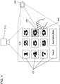
FIG 4 depicts a car operating panel according to one or more embodiments. Thecar operating panel 314 includesvirtual elements 402. In the illustrative example, thevirtual elements 402 are virtual buttons but in one or more embodiments, thevirtual elements 402 can be a variety of media including images, videos, shapes, designs, themes, and the like. In one or more embodiments, a passenger can activate theelevator car 304 or change the configuration of thecar operating panel 314 by activating one of thevirtual elements 402. Thecar operating panel 314 is projected by theprojector 306 and thecamera 310 captures media associated with thecar operating panel 314. In one or more embodiments, thecamera 310 captures a passenger's hand movements with respect to thevirtual elements 402 of thecar operating panel 314. To activate avirtual element 402, the passenger can move his or her finger to alocation 406 on thevirtual element 406. In the illustrated example, the user's finger is found to be at or around thelocation 406 on the '6' button (e.g., virtual element) which corresponds to an elevator call to the sixth floor of a building. - In one or more embodiments, when a
virtual element 402 is activated by a passenger, it can change colors, size, shape, or shading to indicate that the selection has been received or acknowledged by thecar operating panel 314. In some cases, a passenger's hand might be at more than one location. In the illustrated example, the index finger of the passenger is at thefirst location 406 and also the passenger's thumb is shown to be at asecond location 408 which corresponds to the '9' button (e.g., virtual element). Thecamera 310 captures the media of the passenger's hand and transmits the media to thecontroller 302. Thecontroller 302, utilizing logic, can determine a confidence interval for thefirst location 406 and thesecond location 408 to determine which location (region in the virtual element) is being selected by the passenger. The locations with the highest confidence interval can be chosen as the virtual element being selected by the passenger. In the illustrative example, the '6' button is the button being selected. In one or more embodiments, if the confidence interval is below a confidence threshold, thecar operating panel 314 can alert the passenger to adjust their selection by moving their hand or finger to a region more indicative of their selection. The alert could be in the form of a message text on thecar operating panel 314 or thecar operating panel 314 projection can be augmented in size, shape, color, or shading to alert the passenger to make another selection. While the illustrated example utilizes thecamera 310 to detect a selection or activation ofvirtual elements 402 of thecar operating panel 314, any type ofsensor 312 can be utilized to detect a passenger's selection of avirtual element 402. - In one or more embodiments, the car operating penal 314 can operate in several modes such as a first mode that displays basic
virtual elements 402 such as numbering or one or two word buttons as illustrated inFIG. 4 . Also, a second mode can be utilized that displays descriptive virtual elements.FIG. 5 depicts a car operating panel displaying descriptive virtual elements according to one or more embodiments. Thecar operating panel 314 is projected by aprojector 306 with thecamera 310 capturing media associated with thecar operating panel 314. One or morevirtual elements 502 are displayed in the car operating panel. In the illustrative example, thevirtual elements 502 are descriptive indicating office tenants that can be accessed by anelevator car 304. -
FIGs. 4 and5 are illustrative of car operating panels and are not meant to limit the scope of the car operating panels. In one or more embodiments, acar operating panel 314 can display a variety of themes and virtual elements that match the themes. For example, an elevator car at an aquarium can utilize a marine theme and the virtual elements could be in the shape and color of aquatic animals. A number of themes can be stored on thedatabase 322 and accessed through thenetwork 320 by the controller. The user device 324 can access the themes on thedatabase 322 and adjust the themes for thecar operating panel 314 in real time. Themes for thecar operating panel 314 can be scheduled throughout a day, week, month or year for special holidays or events corresponding to the building events scheduled. - In one or more embodiments, the
car operating panel 314 can operate in a third mode or power savings mode. The power savings mode can turn off the projection of thecar operating panel 314 or dim the lighting of the projectedcar operating panel 314. Acar operating panel 314 can enter power savings mode when theelevator car 304 has no passengers or is in an idle mode and is not moving. - In one or more embodiments, to activate a
virtual element 402, the passenger can maneuver his or her hand to a region at or near the desired virtual element. As the passenger's hand is present at the region at the virtual element for a duration of time, the virtual element is activated and thecontroller 402 can receive a signal indicating to engage theelevator car 304. In one or more embodiments, the passenger's hand or finger can utilize a movement pattern to activate thevirtual element 402. For example, thecar operating panel 314 can display multiplevirtual elements 402 and a passenger can move his or her finger through the virtual element as if pushing a physical representation of the virtual element. This finger movement through the virtual element (e.g., movement pattern) can be recognized by thecontroller 302 to indicate activation of the virtual element. - In one or more embodiments, the
car operating panel 314 can include a doodle for the associated theme of thecar operating panel 314. The doodle can change periodically (e.g., hourly, daily, etc.) to resemble a specialty of a particular day. The doodle can include a search feature that allows passengers to search for tenants in the building or other searchable features for the building or region. - In one or more embodiments, the voice sensor 308 can be utilized to assist passengers that are unable to utilize the
car operating panel 314. For example, a blind passenger will not be able to see the projection and can utilize voice commands to activate the elevator commands. In one or more embodiments, theprojector 306 can project thecar operating panel 314 on to a specific surface in theelevator car 304. The surface of theelevator car 304 can have braille engraved at regions that correspond to virtual elements of thecar operating panel 314. This can assist blind passengers with activating the virtual elements to indicate a desired floor. In one or more embodiments, thecamera 310 can capture hand movements and gestures from passengers that may need assistance. Image processing techniques can be utilized for gesture recognition for passengers. - In one or more embodiments, the
elevator car 304 can have a near field communication (NFC) transceiver affixed to it to communicate with the user device 324 that has a corresponding NFC transceiver. The user device 324 can transmit signals to thecontroller 302 to indicate the passenger can access restricted floors and the projection of thecar operating panel 314 can display virtual elements corresponding to the restricted floors for the passenger. - In one or more embodiments, the
database 322 can store new themes and software updates that can be transmitted to thecontroller 302 to update thecare operating panel 314 in theelevator car 304. - In one or more embodiments, the
camera 310 utilizing image recognition techniques can determine physical features of a passenger to project thecar operating panel 314 at a location that is convenient for the passenger. For example, passengers that are shorter might require thecar operating panel 314 to be projected at a lower location in theelevator car 304 for ease of use. -
FIG. 6 depicts a flow diagram of a method for inspecting an elevator system according to one or more embodiments. Themethod 600 includes receiving an indication of a presence of a passenger in an elevator car, as shown atblock 602. Atblock 604, themethod 600 includes projecting, by the projector, a car operating panel in the elevator car, wherein the car operating panel comprises a virtual element. Themethod 600 then includes sensing, by a sensor, an activation of the virtual element from the passenger, as shown atblock 606. And atblock 608, themethod 600 includes initiating an action based at least in part on sensing the activation of the virtual element. - Additional processes may also be included. It should be understood that the processes depicted in
FIG. 6 represent illustrations and that other processes may be added or existing processes may be removed, modified, or rearranged without departing from the scope and spirit of the present disclosure. - A detailed description of one or more embodiments of the disclosed apparatus and method are presented herein by way of exemplification and not limitation with reference to the Figures.
- The term "about" is intended to include the degree of error associated with measurement of the particular quantity based upon the equipment available at the time of filing the application.
- The terminology used herein is for the purpose of describing particular embodiments only and is not intended to be limiting of the present disclosure. As used herein, the singular forms "a", "an" and "the" are intended to include the plural forms as well, unless the context clearly indicates otherwise. It will be further understood that the terms "comprises" and/or "comprising," when used in this specification, specify the presence of stated features, integers, steps, operations, elements, and/or components, but do not preclude the presence or addition of one or more other features, integers, steps, operations, element components, and/or groups thereof.
- While the present disclosure has been described with reference to an exemplary embodiment or embodiments, it will be understood by those skilled in the art that various changes may be made and equivalents may be substituted for elements thereof without departing from the scope of the present disclosure. In addition, many modifications may be made to adapt a particular situation or material to the teachings of the present disclosure without departing from the essential scope thereof. Therefore, it is intended that the present disclosure not be limited to the particular embodiment disclosed as the best mode contemplated for carrying out this present disclosure, but that the present disclosure will include all embodiments falling within the scope of the claims.
Claims (15)
- An elevator system comprising:an elevator car, a sensor, and a projector affixed to the elevator car, wherein the projector is operated by a controller; andwherein the controller is configured to:receive an indication of a presence of a passenger in the elevator car;project, by the projector, a car operating panel in the elevator car, wherein the car operating panel comprises a virtual element;sense, by the sensor, an activation of the virtual element from the passenger; andinitiate an action based at least in part on sensing the activation of the virtual element.
- The elevator system of Claim 1, the action comprises: initiating an elevator command for the elevator car.
- The elevator system of Claim 1 or 2, the action comprises:adding, by the controller, a second virtual element to the car operating panel; andprojecting, by the projector, the second virtual element in the car operating panel.
- The elevator system of any preceding claim, wherein the activation of the virtual element from the passenger comprises:
engaging, by the passenger, a region in the virtual element for a duration of time. - The elevator system of any preceding claim, wherein the activation of the virtual element from the passenger comprises:
engaging, by the passenger, a region in the virtual element utilizing a movement pattern. - The elevator system of any preceding claim, wherein the virtual element comprises a first color; and
responsive to sensing the activation of the virtual element from the passenger, the virtual element changes to a second color. - The elevator system of any preceding claim, wherein the controller is further configured to:periodically detect, by the sensor, the presence of the passenger; andresponsive to the passenger exiting the elevator car, initiating a power savings mode for the car operating panel.
- The elevator system of any preceding claim, wherein the car operating panel is projected on to a surface of the elevator car.
- The elevator system of any preceding claim, wherein the car operating panel comprises a first mode and a second mode;
wherein the first mode comprises a minimal display of the virtual element; and
wherein the second mode comprises a descriptive display of the virtual element. - The elevator system of Claim 9, wherein the initiating the action comprises projecting, by the projector, the second mode for the car operating panel.
- The elevator system of any preceding claim, wherein the controller is further operable to:determine a location of the passenger in the elevator car; andwherein the car operating panel is projected to a second location proximate to the location of the passenger.
- The elevator system of any preceding claim, wherein the car operating panel further comprises a news feed.
- The elevator system of any preceding claim further comprising a microphone, wherein the microphone is operated by the controller; and
wherein the controller is further configured to:receive an audio command from the user; andresponsive to the audio command from the user, initiate a second action for the elevator car. - A computer-implemented method for operating an elevator system comprising:receiving an indication of a presence of a passenger in an elevator car;projecting, by the projector, a car operating panel in the elevator car, wherein the car operating panel comprises a virtual element;sensing, by a sensor, an activation of the virtual element from the passenger; andinitiating an action based at least in part on sensing the activation of the virtual element.
- The method of Claim 14 further comprising:periodically detecting, by the sensor, the presence of the passenger; andresponsive to the passenger exiting the elevator car, initiating a power savings mode for the car operating panel.
Applications Claiming Priority (1)
| Application Number | Priority Date | Filing Date | Title |
|---|---|---|---|
| IN201811009167 | 2018-03-13 |
Publications (1)
| Publication Number | Publication Date |
|---|---|
| EP3556702A1 true EP3556702A1 (en) | 2019-10-23 |
Family
ID=65801927
Family Applications (1)
| Application Number | Title | Priority Date | Filing Date |
|---|---|---|---|
| EP19162375.0A Pending EP3556702A1 (en) | 2018-03-13 | 2019-03-12 | Augmented reality car operating panel |
Country Status (2)
| Country | Link |
|---|---|
| US (1) | US11420846B2 (en) |
| EP (1) | EP3556702A1 (en) |
Cited By (1)
| Publication number | Priority date | Publication date | Assignee | Title |
|---|---|---|---|---|
| CN111517188A (en) * | 2020-05-11 | 2020-08-11 | 深圳市呤云科技有限公司 | Non-contact ladder control device and method |
Families Citing this family (5)
| Publication number | Priority date | Publication date | Assignee | Title |
|---|---|---|---|---|
| CN107709208A (en) * | 2015-05-21 | 2018-02-16 | 奥的斯电梯公司 | Contactless lift call button |
| EP3412613B1 (en) * | 2017-06-07 | 2024-03-13 | Otis Elevator Company | Hand detection for elevator operation |
| EP3556702A1 (en) * | 2018-03-13 | 2019-10-23 | Otis Elevator Company | Augmented reality car operating panel |
| CN212668888U (en) * | 2020-06-29 | 2021-03-09 | 衍视电子科技(上海)有限公司 | Holographic elevator control box |
| EP4112524A1 (en) * | 2021-07-01 | 2023-01-04 | Kleemann Hellas SA | Retrofit contact to contactless elevator buttons |
Citations (3)
| Publication number | Priority date | Publication date | Assignee | Title |
|---|---|---|---|---|
| KR20070099783A (en) * | 2006-04-05 | 2007-10-10 | 고유정 | Laser button of elevator |
| JP2010143683A (en) * | 2008-12-17 | 2010-07-01 | Mitsubishi Electric Building Techno Service Co Ltd | Car call registering device for elevator |
| CN105197702A (en) * | 2015-10-20 | 2015-12-30 | 苏州钜立智能系统有限公司 | Elevator control panel |
Family Cites Families (38)
| Publication number | Priority date | Publication date | Assignee | Title |
|---|---|---|---|---|
| US4969700A (en) | 1987-12-23 | 1990-11-13 | American Bank Note Holographics, Inc. | Computer aided holography and holographic computer graphics |
| US6031519A (en) | 1997-12-30 | 2000-02-29 | O'brien; Wayne P. | Holographic direct manipulation interface |
| FR2779559B1 (en) * | 1998-06-09 | 2000-07-21 | Otis Elevator Co | METHOD AND DEVICE FOR DISPLAYING A VIRTUAL IMAGE, IN PARTICULAR FROM THE CONTROL PANEL OF AN ELEVATOR CAB |
| CA2530987C (en) | 2003-07-03 | 2012-04-17 | Holotouch, Inc. | Holographic human-machine interfaces |
| WO2005113399A1 (en) | 2004-04-30 | 2005-12-01 | Otis Elevator Company | Haptic hologram-enabled elevator call buttons |
| US20050277467A1 (en) | 2004-06-14 | 2005-12-15 | Jcm American Corporation, A Nevada Corporation | Gaming machine using holographic imaging |
| US8089456B2 (en) | 2004-06-30 | 2012-01-03 | Telecom Italia S.P.A. | Inputting information using holographic techniques |
| JP2008013299A (en) | 2006-07-05 | 2008-01-24 | Mitsubishi Electric Corp | Destination floor registering device of elevator |
| US7881901B2 (en) | 2007-09-18 | 2011-02-01 | Gefemer Research Acquisitions, Llc | Method and apparatus for holographic user interface communication |
| US8212768B2 (en) | 2007-10-31 | 2012-07-03 | Fimed Properties Ag Limited Liability Company | Digital, data, and multimedia user interface with a keyboard |
| US8127251B2 (en) | 2007-10-31 | 2012-02-28 | Fimed Properties Ag Limited Liability Company | Method and apparatus for a user interface with priority data |
| US8477098B2 (en) | 2007-10-31 | 2013-07-02 | Gene S. Fein | Method and apparatus for user interface of input devices |
| KR101908033B1 (en) | 2008-07-10 | 2018-12-10 | 리얼 뷰 이미징 리미티드 | Broad viewing angle displays and user interfaces |
| GB2466497B (en) | 2008-12-24 | 2011-09-14 | Light Blue Optics Ltd | Touch sensitive holographic displays |
| CN202661719U (en) | 2009-03-10 | 2013-01-09 | 3M创新有限公司 | User interface having projected synthetic image |
| US20100253700A1 (en) | 2009-04-02 | 2010-10-07 | Philippe Bergeron | Real-Time 3-D Interactions Between Real And Virtual Environments |
| US8547327B2 (en) | 2009-10-07 | 2013-10-01 | Qualcomm Incorporated | Proximity object tracker |
| KR101045842B1 (en) * | 2010-06-30 | 2011-07-01 | 유재혁 | Apparatus for recogniging voice of elevator and method for controling the same |
| US9773345B2 (en) | 2012-02-15 | 2017-09-26 | Nokia Technologies Oy | Method and apparatus for generating a virtual environment for controlling one or more electronic devices |
| CN103373650B (en) | 2012-04-11 | 2016-03-09 | 上海智显光电科技有限公司 | There is the elevator control dial of information inquiry Presentation Function |
| FI124166B (en) * | 2013-01-08 | 2014-04-15 | Kone Corp | An elevator call system and a method for providing lift calls in an elevator call system |
| WO2015004670A1 (en) | 2013-07-10 | 2015-01-15 | Real View Imaging Ltd. | Three dimensional user interface |
| CN105473483B (en) * | 2013-08-21 | 2017-07-25 | 三菱电机株式会社 | Elevator control gear |
| CN204416809U (en) | 2014-12-31 | 2015-06-24 | 福州环奥电梯工程有限公司 | Line holographic projections elevator lifting controller |
| CN204400366U (en) | 2014-12-31 | 2015-06-17 | 福州环奥电梯工程有限公司 | Line holographic projections elevator cage controlling box |
| US10732721B1 (en) * | 2015-02-28 | 2020-08-04 | sigmund lindsay clements | Mixed reality glasses used to operate a device touch freely |
| US10740290B2 (en) | 2015-04-14 | 2020-08-11 | Jetflow Technologies | Systems and methods for key-value stores |
| CN204802795U (en) | 2015-05-25 | 2015-11-25 | 北京索德电气工业有限公司 | Intelligence holographically projected calling board |
| US10294069B2 (en) | 2016-04-28 | 2019-05-21 | Thyssenkrupp Elevator Ag | Multimodal user interface for destination call request of elevator systems using route and car selection methods |
| CN205634507U (en) | 2016-05-23 | 2016-10-12 | 北京索德电气工业有限公司 | Touch projection calling board |
| CN105967019A (en) | 2016-07-20 | 2016-09-28 | 甘庆 | Elevator intelligent perspective projection device |
| CN205953247U (en) | 2016-07-20 | 2017-02-15 | 甘庆 | Elevator intelligence perspective projection device |
| EP3299323B1 (en) * | 2016-09-23 | 2020-04-01 | Otis Elevator Company | Secondary car operating panel for elevator cars |
| EP3315443B1 (en) * | 2016-10-26 | 2021-03-24 | Otis Elevator Company | Elevator virtual hall call panel systems and methods of operation |
| CN109422147A (en) * | 2017-08-28 | 2019-03-05 | 奥的斯电梯公司 | Verbal order interface |
| EP3556702A1 (en) * | 2018-03-13 | 2019-10-23 | Otis Elevator Company | Augmented reality car operating panel |
| CN112839890B (en) * | 2018-10-16 | 2023-04-21 | 通力股份公司 | Interface device, elevator system and method for controlling display of multiple destination calls |
| US20210206598A1 (en) * | 2020-01-07 | 2021-07-08 | Thyssenkrupp Elevator Innovation And Operations Gmbh | Systems and methods for displaying cabin operating panels in elevator cabs based on positions of passengers |
-
2019
- 2019-03-12 EP EP19162375.0A patent/EP3556702A1/en active Pending
- 2019-03-13 US US16/352,187 patent/US11420846B2/en active Active
Patent Citations (3)
| Publication number | Priority date | Publication date | Assignee | Title |
|---|---|---|---|---|
| KR20070099783A (en) * | 2006-04-05 | 2007-10-10 | 고유정 | Laser button of elevator |
| JP2010143683A (en) * | 2008-12-17 | 2010-07-01 | Mitsubishi Electric Building Techno Service Co Ltd | Car call registering device for elevator |
| CN105197702A (en) * | 2015-10-20 | 2015-12-30 | 苏州钜立智能系统有限公司 | Elevator control panel |
Cited By (1)
| Publication number | Priority date | Publication date | Assignee | Title |
|---|---|---|---|---|
| CN111517188A (en) * | 2020-05-11 | 2020-08-11 | 深圳市呤云科技有限公司 | Non-contact ladder control device and method |
Also Published As
| Publication number | Publication date |
|---|---|
| US11420846B2 (en) | 2022-08-23 |
| US20190284020A1 (en) | 2019-09-19 |
Similar Documents
| Publication | Publication Date | Title |
|---|---|---|
| US11420846B2 (en) | Augmented reality car operating panel | |
| CA2967723C (en) | System and method for alternatively interacting with elevators | |
| EP3299323B1 (en) | Secondary car operating panel for elevator cars | |
| US20120234631A1 (en) | Simple node transportation system and control method thereof | |
| CN109982758B (en) | Amusement park scene point control management system and method | |
| CN101356107A (en) | Information display in elevator car | |
| KR101394375B1 (en) | Elevator control apparatus | |
| CN111377325B (en) | System and method for enhancing elevator sensor operation | |
| JP2015013695A (en) | Destination floor registering device of elevator | |
| CN113148788B (en) | System and method for displaying car operating panel in elevator car based on passenger positioning | |
| EP3805137A1 (en) | Mobile interface, communication, and control system to facilitate operation of elevator cars with media options | |
| CN110606433B (en) | Floor neglect of elevator | |
| CN114839782A (en) | Vehicle-mounted enhanced display system for vehicle control and information display | |
| US20190292013A1 (en) | Service tool with capture and replay | |
| WO2017050673A1 (en) | An arrangement for providing a user interface | |
| US20210165542A1 (en) | Solution for providing visual output representing maintenance related information of a people transport system or an acess control system | |
| EP3543189B1 (en) | Elevator car operation based on its occupancy | |
| US10824126B2 (en) | Device and method for the gesture control of a screen in a control room | |
| CN116324952A (en) | System and method for processing boarding information and generating organic virtual wizards, and corresponding apparatus and computer readable memory | |
| Al Mansur et al. | Design and development of PC based elevator control systems via ATmega32 microcontroller | |
| JP4519468B2 (en) | Function guidance device | |
| KR20120101744A (en) | Elevator with input output user equipment | |
| WO2021140551A1 (en) | Elevator control system |
Legal Events
| Date | Code | Title | Description |
|---|---|---|---|
| PUAI | Public reference made under article 153(3) epc to a published international application that has entered the european phase |
Free format text: ORIGINAL CODE: 0009012 |
|
| STAA | Information on the status of an ep patent application or granted ep patent |
Free format text: STATUS: THE APPLICATION HAS BEEN PUBLISHED |
|
| AK | Designated contracting states |
Kind code of ref document: A1 Designated state(s): AL AT BE BG CH CY CZ DE DK EE ES FI FR GB GR HR HU IE IS IT LI LT LU LV MC MK MT NL NO PL PT RO RS SE SI SK SM TR |
|
| AX | Request for extension of the european patent |
Extension state: BA ME |
|
| STAA | Information on the status of an ep patent application or granted ep patent |
Free format text: STATUS: REQUEST FOR EXAMINATION WAS MADE |
|
| 17P | Request for examination filed |
Effective date: 20200423 |
|
| RBV | Designated contracting states (corrected) |
Designated state(s): AL AT BE BG CH CY CZ DE DK EE ES FI FR GB GR HR HU IE IS IT LI LT LU LV MC MK MT NL NO PL PT RO RS SE SI SK SM TR |
|
| STAA | Information on the status of an ep patent application or granted ep patent |
Free format text: STATUS: EXAMINATION IS IN PROGRESS |
|
| 17Q | First examination report despatched |
Effective date: 20220222 |