EP3556670A1 - Robot system and cutting blade - Google Patents
Robot system and cutting blade Download PDFInfo
- Publication number
- EP3556670A1 EP3556670A1 EP17880315.1A EP17880315A EP3556670A1 EP 3556670 A1 EP3556670 A1 EP 3556670A1 EP 17880315 A EP17880315 A EP 17880315A EP 3556670 A1 EP3556670 A1 EP 3556670A1
- Authority
- EP
- European Patent Office
- Prior art keywords
- workpiece
- adhesive member
- blade
- clamping
- cutting
- Prior art date
- Legal status (The legal status is an assumption and is not a legal conclusion. Google has not performed a legal analysis and makes no representation as to the accuracy of the status listed.)
- Granted
Links
Images









Classifications
-
- B—PERFORMING OPERATIONS; TRANSPORTING
- B25—HAND TOOLS; PORTABLE POWER-DRIVEN TOOLS; MANIPULATORS
- B25J—MANIPULATORS; CHAMBERS PROVIDED WITH MANIPULATION DEVICES
- B25J11/00—Manipulators not otherwise provided for
-
- B—PERFORMING OPERATIONS; TRANSPORTING
- B25—HAND TOOLS; PORTABLE POWER-DRIVEN TOOLS; MANIPULATORS
- B25J—MANIPULATORS; CHAMBERS PROVIDED WITH MANIPULATION DEVICES
- B25J9/00—Program-controlled manipulators
- B25J9/16—Program controls
- B25J9/1679—Program controls characterised by the tasks executed
- B25J9/1687—Assembly, peg and hole, palletising, straight line, weaving pattern movement
-
- B—PERFORMING OPERATIONS; TRANSPORTING
- B25—HAND TOOLS; PORTABLE POWER-DRIVEN TOOLS; MANIPULATORS
- B25J—MANIPULATORS; CHAMBERS PROVIDED WITH MANIPULATION DEVICES
- B25J9/00—Program-controlled manipulators
- B25J9/0096—Program-controlled manipulators co-operating with a working support, e.g. work-table
-
- B—PERFORMING OPERATIONS; TRANSPORTING
- B25—HAND TOOLS; PORTABLE POWER-DRIVEN TOOLS; MANIPULATORS
- B25J—MANIPULATORS; CHAMBERS PROVIDED WITH MANIPULATION DEVICES
- B25J15/00—Gripping heads and other end effectors
- B25J15/0019—End effectors other than grippers
-
- B—PERFORMING OPERATIONS; TRANSPORTING
- B25—HAND TOOLS; PORTABLE POWER-DRIVEN TOOLS; MANIPULATORS
- B25J—MANIPULATORS; CHAMBERS PROVIDED WITH MANIPULATION DEVICES
- B25J15/00—Gripping heads and other end effectors
- B25J15/0052—Gripping heads and other end effectors multiple gripper units or multiple end effectors
- B25J15/0066—Gripping heads and other end effectors multiple gripper units or multiple end effectors with different types of end effectors, e.g. gripper and welding gun
-
- B—PERFORMING OPERATIONS; TRANSPORTING
- B25—HAND TOOLS; PORTABLE POWER-DRIVEN TOOLS; MANIPULATORS
- B25J—MANIPULATORS; CHAMBERS PROVIDED WITH MANIPULATION DEVICES
- B25J15/00—Gripping heads and other end effectors
- B25J15/02—Gripping heads and other end effectors servo-actuated
- B25J15/0206—Gripping heads and other end effectors servo-actuated comprising articulated grippers
-
- B—PERFORMING OPERATIONS; TRANSPORTING
- B25—HAND TOOLS; PORTABLE POWER-DRIVEN TOOLS; MANIPULATORS
- B25J—MANIPULATORS; CHAMBERS PROVIDED WITH MANIPULATION DEVICES
- B25J15/00—Gripping heads and other end effectors
- B25J15/02—Gripping heads and other end effectors servo-actuated
- B25J15/0253—Gripping heads and other end effectors servo-actuated comprising parallel grippers
- B25J15/0293—Gripping heads and other end effectors servo-actuated comprising parallel grippers having fingers directly connected to actuator
-
- B—PERFORMING OPERATIONS; TRANSPORTING
- B25—HAND TOOLS; PORTABLE POWER-DRIVEN TOOLS; MANIPULATORS
- B25J—MANIPULATORS; CHAMBERS PROVIDED WITH MANIPULATION DEVICES
- B25J15/00—Gripping heads and other end effectors
- B25J15/08—Gripping heads and other end effectors having finger members
-
- B—PERFORMING OPERATIONS; TRANSPORTING
- B26—HAND CUTTING TOOLS; CUTTING; SEVERING
- B26D—CUTTING; DETAILS COMMON TO MACHINES FOR PERFORATING, PUNCHING, CUTTING-OUT, STAMPING-OUT OR SEVERING
- B26D1/00—Cutting through work characterised by the nature or movement of the cutting member or particular materials not otherwise provided for; Apparatus or machines therefor; Cutting members therefor
- B26D1/01—Cutting through work characterised by the nature or movement of the cutting member or particular materials not otherwise provided for; Apparatus or machines therefor; Cutting members therefor involving a cutting member which does not travel with the work
- B26D1/04—Cutting through work characterised by the nature or movement of the cutting member or particular materials not otherwise provided for; Apparatus or machines therefor; Cutting members therefor involving a cutting member which does not travel with the work having a linearly-movable cutting member
- B26D1/06—Cutting through work characterised by the nature or movement of the cutting member or particular materials not otherwise provided for; Apparatus or machines therefor; Cutting members therefor involving a cutting member which does not travel with the work having a linearly-movable cutting member wherein the cutting member reciprocates
- B26D1/065—Cutting through work characterised by the nature or movement of the cutting member or particular materials not otherwise provided for; Apparatus or machines therefor; Cutting members therefor involving a cutting member which does not travel with the work having a linearly-movable cutting member wherein the cutting member reciprocates for thin material, e.g. for sheets, strips or the like
-
- B—PERFORMING OPERATIONS; TRANSPORTING
- B65—CONVEYING; PACKING; STORING; HANDLING THIN OR FILAMENTARY MATERIAL
- B65C—LABELLING OR TAGGING MACHINES, APPARATUS, OR PROCESSES
- B65C3/00—Labelling other than flat surfaces
-
- B—PERFORMING OPERATIONS; TRANSPORTING
- B65—CONVEYING; PACKING; STORING; HANDLING THIN OR FILAMENTARY MATERIAL
- B65C—LABELLING OR TAGGING MACHINES, APPARATUS, OR PROCESSES
- B65C9/00—Details of labelling machines or apparatus
- B65C9/26—Devices for applying labels
-
- B—PERFORMING OPERATIONS; TRANSPORTING
- B65—CONVEYING; PACKING; STORING; HANDLING THIN OR FILAMENTARY MATERIAL
- B65C—LABELLING OR TAGGING MACHINES, APPARATUS, OR PROCESSES
- B65C9/00—Details of labelling machines or apparatus
- B65C9/26—Devices for applying labels
- B65C9/30—Rollers
-
- B—PERFORMING OPERATIONS; TRANSPORTING
- B65—CONVEYING; PACKING; STORING; HANDLING THIN OR FILAMENTARY MATERIAL
- B65H—HANDLING THIN OR FILAMENTARY MATERIAL, e.g. SHEETS, WEBS, CABLES
- B65H35/00—Delivering articles from cutting or line-perforating machines; Article or web delivery apparatus incorporating cutting or line-perforating devices, e.g. adhesive tape dispensers
-
- B—PERFORMING OPERATIONS; TRANSPORTING
- B65—CONVEYING; PACKING; STORING; HANDLING THIN OR FILAMENTARY MATERIAL
- B65H—HANDLING THIN OR FILAMENTARY MATERIAL, e.g. SHEETS, WEBS, CABLES
- B65H35/00—Delivering articles from cutting or line-perforating machines; Article or web delivery apparatus incorporating cutting or line-perforating devices, e.g. adhesive tape dispensers
- B65H35/04—Delivering articles from cutting or line-perforating machines; Article or web delivery apparatus incorporating cutting or line-perforating devices, e.g. adhesive tape dispensers from or with transverse cutters or perforators
- B65H35/06—Delivering articles from cutting or line-perforating machines; Article or web delivery apparatus incorporating cutting or line-perforating devices, e.g. adhesive tape dispensers from or with transverse cutters or perforators from or with blade, e.g. shear-blade, cutters or perforators
-
- B—PERFORMING OPERATIONS; TRANSPORTING
- B25—HAND TOOLS; PORTABLE POWER-DRIVEN TOOLS; MANIPULATORS
- B25J—MANIPULATORS; CHAMBERS PROVIDED WITH MANIPULATION DEVICES
- B25J11/00—Manipulators not otherwise provided for
- B25J11/005—Manipulators for mechanical processing tasks
- B25J11/0055—Cutting
-
- B—PERFORMING OPERATIONS; TRANSPORTING
- B25—HAND TOOLS; PORTABLE POWER-DRIVEN TOOLS; MANIPULATORS
- B25J—MANIPULATORS; CHAMBERS PROVIDED WITH MANIPULATION DEVICES
- B25J15/00—Gripping heads and other end effectors
- B25J15/0052—Gripping heads and other end effectors multiple gripper units or multiple end effectors
-
- B—PERFORMING OPERATIONS; TRANSPORTING
- B25—HAND TOOLS; PORTABLE POWER-DRIVEN TOOLS; MANIPULATORS
- B25J—MANIPULATORS; CHAMBERS PROVIDED WITH MANIPULATION DEVICES
- B25J15/00—Gripping heads and other end effectors
- B25J15/008—Gripping heads and other end effectors with sticking, gluing or adhesive means
-
- B—PERFORMING OPERATIONS; TRANSPORTING
- B25—HAND TOOLS; PORTABLE POWER-DRIVEN TOOLS; MANIPULATORS
- B25J—MANIPULATORS; CHAMBERS PROVIDED WITH MANIPULATION DEVICES
- B25J9/00—Program-controlled manipulators
- B25J9/02—Program-controlled manipulators characterised by movement of the arms, e.g. cartesian coordinate type
- B25J9/04—Program-controlled manipulators characterised by movement of the arms, e.g. cartesian coordinate type by rotating at least one arm, excluding the head movement itself, e.g. cylindrical coordinate type or polar coordinate type
- B25J9/041—Cylindrical coordinate type
- B25J9/042—Cylindrical coordinate type comprising an articulated arm
-
- B—PERFORMING OPERATIONS; TRANSPORTING
- B25—HAND TOOLS; PORTABLE POWER-DRIVEN TOOLS; MANIPULATORS
- B25J—MANIPULATORS; CHAMBERS PROVIDED WITH MANIPULATION DEVICES
- B25J9/00—Program-controlled manipulators
- B25J9/16—Program controls
- B25J9/1679—Program controls characterised by the tasks executed
-
- B—PERFORMING OPERATIONS; TRANSPORTING
- B26—HAND CUTTING TOOLS; CUTTING; SEVERING
- B26D—CUTTING; DETAILS COMMON TO MACHINES FOR PERFORATING, PUNCHING, CUTTING-OUT, STAMPING-OUT OR SEVERING
- B26D1/00—Cutting through work characterised by the nature or movement of the cutting member or particular materials not otherwise provided for; Apparatus or machines therefor; Cutting members therefor
- B26D1/0006—Cutting members therefor
- B26D2001/0033—Cutting members therefor assembled from multiple blades
-
- B—PERFORMING OPERATIONS; TRANSPORTING
- B26—HAND CUTTING TOOLS; CUTTING; SEVERING
- B26D—CUTTING; DETAILS COMMON TO MACHINES FOR PERFORATING, PUNCHING, CUTTING-OUT, STAMPING-OUT OR SEVERING
- B26D1/00—Cutting through work characterised by the nature or movement of the cutting member or particular materials not otherwise provided for; Apparatus or machines therefor; Cutting members therefor
- B26D1/0006—Cutting members therefor
- B26D2001/004—Cutting members therefor not rotating
-
- B—PERFORMING OPERATIONS; TRANSPORTING
- B65—CONVEYING; PACKING; STORING; HANDLING THIN OR FILAMENTARY MATERIAL
- B65H—HANDLING THIN OR FILAMENTARY MATERIAL, e.g. SHEETS, WEBS, CABLES
- B65H2301/00—Handling processes for sheets or webs
- B65H2301/50—Auxiliary process performed during handling process
- B65H2301/51—Modifying a characteristic of handled material
- B65H2301/515—Cutting handled material
- B65H2301/5153—Details of cutting means
- B65H2301/51532—Blade cutter, e.g. single blade cutter
-
- B—PERFORMING OPERATIONS; TRANSPORTING
- B65—CONVEYING; PACKING; STORING; HANDLING THIN OR FILAMENTARY MATERIAL
- B65H—HANDLING THIN OR FILAMENTARY MATERIAL, e.g. SHEETS, WEBS, CABLES
- B65H2701/00—Handled material; Storage means
- B65H2701/10—Handled articles or webs
- B65H2701/17—Nature of material
- B65H2701/174—Textile; fibres
Definitions
- the present invention relates to a robot system capable of clamping and sticking an adhesive member, such as a nonwoven fabric, on an object, such as an automobile interior member (for example, deck board) and further relates to a cutting blade used for cutting and forming the adhesive member.
- an adhesive member such as a nonwoven fabric
- an object such as an automobile interior member (for example, deck board)
- a cutting blade used for cutting and forming the adhesive member.
- PTL 1 discloses a technique for separating an attached material covering an adhesive part of a target object by means of an attached material separation unit with a needle unit.
- the attached material on the target object approaches a sharp point of the needle unit at a predetermined approach angle to separate the attached material from the target object.
- PTL 1 requires some labor and time for a setting of a robot since a method of separating the attached material is complicated.
- the present invention has been made in view of such a circumstance and is to provide a robot system capable of separating an adhesive member from a cover material and sticking the adhesive member on an object without a complicated setting.
- a robot system comprising a sticking mechanism configured to clamp and stick at least one adhesive member on an object and a supply mechanism capable of supplying the adhesive member, wherein: the sticking mechanism comprises a robot hand configured to clamp and release the adhesive member and a robot arm configured to move the robot hand; the supply mechanism is separate from the sticking mechanism, supplies the adhesive member in a state that the adhesive member is stuck to a cover material, and separates the cover material from the adhesive member by bending the cover material in a direction away from the adhesive member in order to enable the robot hand to clamp the adhesive member in a state that the cover material is separated from the adhesive member.
- the robot hand is configured to clamp the adhesive member while the adhesive member is separated from the cover material by bending the cover material, and thus it is possible to separate the adhesive member from the cover material and stick the adhesive member on the object without a complicated setting.
- the robot hand can be downsized.
- the robot hand comprises at least one clamping unit configured to clamp and release the adhesive member.
- the clamping unit comprises a clamping mechanism configured to clamp and release the adhesive member and a pressing mechanism configured to press the adhesive member against the object.
- the clamping mechanism comprises a clamping base with a base surface and a first cylinder mechanism, wherein the first cylinder mechanism comprises a first cylinder base and a first rod, a projection length of the first rod from the first cylinder base being variable, and the clamping mechanism is configured to clamp the adhesive member between the base surface and the first rod.
- the pressing mechanism comprises a rotary base rotatable relative to the clamping base and a pressing part provided on the rotary base and pressed against the adhesive member.
- the rotary base is urged in a direction in which the pressing part is pressed against the adhesive member.
- the pressing mechanism comprises a second cylinder mechanism, wherein the second cylinder mechanism comprises a second cylinder base and a second rod, a projection length of the second rod from the second cylinder base is variable, and the pressing mechanism is configured to adjust an angle of the rotary base relative to the clamping base by changing the projection length of the second rod.
- the robot hand comprises a third cylinder mechanism, wherein the third cylinder mechanism comprises a third cylinder base and a third rod, a projection length of the third rod from the third cylinder base is variable, and the clamping unit is provided on the third rod.
- the third cylinder mechanism comprises a third cylinder base and a third rod
- a projection length of the third rod from the third cylinder base is variable
- the clamping unit is provided on the third rod.
- the robot hand comprises a plurality of clamping units arranged in a line, wherein the supply mechanism is configured to supply a plurality of adhesive members arranged in a line, and the robot hand is configured to simultaneously clamp the plurality of adhesive members by the plurality of clamping units.
- the robot hand is configured to cause the plurality of clamping units to project one by one so as to stick the plurality of adhesive members one by one to the object.
- the adhesive member is a nonwoven fabric.
- a robot system 10 of an embodiment of the present invention comprises a sticking mechanism 3 configured to clamp and stick an adhesive member 1 on an object 2 and a supply mechanism 4 capable of supplying an adhesive member 1.
- the sticking mechanism 3 comprises a robot hand 5 configured to clamp and release the adhesive member 1 and a robot arm 6 configured to move the robot hand 5.
- the adhesive member 1 comprises an adhesive layer 1a on one surface and is configured to be stuck on the object 2 by pressing the adhesive member 1 against the object 2 while the adhesive layer 1a faces the object 2.
- the adhesive member 1 is assumed to have a certain thickness.
- the thickness of the adhesive member 1 is, for example, 0.5 to 5 mm, and specifically, for example, 0.5, 1, 1.5, 2, 2.5, 3, 3.5, 4, 4.5, 5 mm and may be within a range between any two of the values exemplified herein.
- the adhesive member 1 is stuck on the object 2 for the purpose of preventing rattling or a vibration, noise reduction, or the like.
- a material thereof is not specifically limited, and may be, for example, a nonwoven fabric.
- the object 2 may be, for example, an automobile interior member, such as a deck board.
- a cover material 7 is stuck on a surface of the adhesive member 1 on a side of the adhesive layer 1a.
- the cover material 7 has a function of covering the adhesive layer 1a.
- a paper or a sheet (so-called release paper) whose surface facing the adhesive layer 1a is subjected to easy peeling treatment is suitably used as the cover material 7.
- a large number of adhesive members 1 are arranged in a grid pattern on the cover material 7.
- Three adhesive members 1 are arranged in a line in a width direction (direction perpendicular to a longitudinal direction) of the cover material 7.
- a large number of adhesive members 1 are continuously arranged in the longitudinal direction of the cover material 7.
- a tape member T configured by arranging a large number of adhesive members 1 on the cover material 7 can be formed by sticking the cover material 7 on an adhesive layer of a large-area sheet and then making a cut (half-cut) in the large-area sheet so as to include the large number of adhesive members 1.
- the adhesive member 1 may be preferably rectangular or square in order to easily manufacture the adhesive member 1 by half cutting of the large-area sheet.
- a length of the adhesive member 1 in a longitudinal direction and a width direction may be preferably 1 to 5 cm, specifically, for example, 1, 2, 3, 4, 5 cm, or may be in a range between any two of the values exemplified herein.
- the supply mechanism 4 comprises a delivery roller R1, a take-up roller R2, and a bending jig 8 provided therebetween.
- a tape member roll in which the tape member T is wound is mounted on the delivery roller R1, and the tape member T is supplied toward a bending jig 8 associated with a rotation of the delivery roller R1 in a rewinding direction.
- the adhesive member 1 is separated from the cover material 7 by the bending jig 8 by bending the cover material 7 in a direction away from the adhesive member 1.
- the adhesive member 1 in this state is clamped by the robot hand 5.
- the cover material 7 is wound up associated with a rotation of the take-up roller R2.
- Rotation speeds of the delivery roller R1 and the take-up roller R2 are adjusted so as to maintain a state in which the cover material 7 is tensioned. Further, a tension roller for adjusting a tension applied to the cover material 7 is provided as needed between the delivery roller R1 and the take-up roller R2.
- the bending jig 8 comprises a tip 8a, an upper surface 8b, and an inclined surface 8c.
- the tip 8a is provided to join with the upper surface 8b and the inclined surface 8c.
- the cover material 7 is guided from the delivery roller R1 to the take-up roller R2 via the upper surface 8b, the tip 8a, and the inclined surface 8c in this order.
- An angle between the upper surface 8b and the inclined surface 8c at the tip 8a is not specifically limited, and may be for example, 15 to 75 degrees, preferably 30 to 60 degrees, and more preferably 40 to 50 degrees. This is because the adhesive member 1 can be easily separated from the cover material 7 in a case of such an angle.
- a radius of curvature of the tip 8a may be preferably equal to or less than a length L of the adhesive member 1 in a longitudinal direction, because the adhesive member 1 can be easily separated from the cover material 7 in such a case.
- the value of the radius of curvature of the tip 8a /length L may be, for example, 0.1 to 1, specifically, for example, 0.01, 0.05, 0.1, 0.2, 0.3, 0.4, 0.5, 0.6, 0.7, 0.8, 0.9, 1, or may be in a range between any two of the values exemplified herein.
- the radius of curvature of the tip 8a may be, for example, 0.1 to 20 mm, preferably, 0.5 to 5 mm, specifically, for example, 0.1, 0.5, 1, 2, 3, 4, 5, 6, 7, 8, 9, 10, 11, 12, 13, 14, 15, 16, 17, 18, 19, 20 mm, or may be in a range between any two of the values exemplified herein.
- a pressing means 26 is provided at a position facing the upper surface 8b. As illustrated in Figs. 1 and 2 , the pressing means 26 is provided so as to press the adhesive members 1 in the second row C2 while the adhesive members 1 in a top row C1 are being separated from the cover material 7, without pressing the adhesive members 1 in the top row C1.
- the robot hand 5 of the sticking mechanism 3 clamps and pick up the adhesive members 1 in the top row C1 while the pressing means 26 presses the adhesive members 1 in the second row C2. This can prevent the adhesive members 1 in the second row C2 from being picked up together.
- the pressing means 26 may press only the adhesive members 1 in the second row C2 or may press the adhesive members 1 in a third and subsequent rows together.
- the pressing means 26 comprises a plate part 26a coming into contact with the adhesive members 1 and a cylinder mechanism 26b for pressing the plate part 26a against the adhesive members 1.
- the sticking mechanism 3 comprises the robot hand 5 and the robot arm 6.
- the robot arm 6 has a function of moving the robot hand 5, and specifically has a function of moving the robot hand 5, after the robot hand 5 clamps and picks up the adhesive member 1, to a position on the object 2 where the adhesive member 1 is stuck.
- the robot arm 6 has any number of shafts necessary to realize the above-described function and may preferably have six or more shafts.
- the robot hand 5 comprises a holding plate 9. As illustrated in Figs. 3A and 3B , nine cylinder mechanisms 13 are fixed to the holding plate 9.
- a cylinder mechanism group 13g includes three cylinder mechanisms 13 adjacent to each other so as to be aligned in a width direction. Therefore, three cylinder mechanism groups 13g are configured from the nine cylinder mechanisms 13 fixed to the holding plate 9. There is a space between adjacent cylinder mechanism groups 13g.
- Each of the cylinder mechanisms 13 comprises a cylinder base 13a and a rod 13 b, a projection length of the rod 13b from the cylinder base 13a being variable.
- a clamping unit 11 is attached to each rod 13b.
- a clamping unit group 11g includes three clamping units 11 adjacent to each other so as to be arranged in a line in a width direction. Three clamping unit groups 11g are configured to correspond to the three cylinder mechanism groups 13g. There is a space between adjacent clamping unit groups.
- Each of the clamping units 11 is configured to clamp and release one adhesive member 1. Therefore, the clamping unit group 11g including the three clamping units 11 arranged in a line in a width direction is configured to simultaneously clamp three adhesive members 1 arranged in a line in a width direction, as illustrated in Fig. 2 .
- a first clamping unit group 11g clamps and picks up three adhesive members 1 in the top row C1
- the delivery roller R1 and the take-up roller R2 rotate by a length of one row in a longitudinal direction of the adhesive member 1, and the adhesive members 1 in the second row C2 are delivered to a position of the top row C1, being separated from the cover material 7.
- a second clamping unit group 11g clamps and picks up the three adhesive members 1 delivered to the position of the top row C1.
- a similar step is performed again, and a third clamping unit group 11g clamps and picks up three adhesive members 1 delivered to the position of the top row C1.
- nine adhesive members 1 are clamped and picked up by nine clamping units 11 by three operations.
- the nine adhesive members 1 clamped by the nine clamping units 11 are stuck one by one on the object 2.
- the adhesive layer 1a of the adhesive member 1 is exposed, and thus if the clamping unit 11 approaches the object 2 to stick one adhesive member 1 on the object 2, another adhesive member 1 may be unintentionally stuck on the object 2.
- one clamping unit 11 is projected beyond the other clamping units 11, as illustrated in Figs. 4A and 4B , by operating the cylinder mechanism 13 to which the clamping unit 11 clamping the adhesive member 1 to be stuck on the object 2 is attached and elongating a projection length of the rod 13b.
- the projecting clamping unit 11 can be closer to the object 2 than the other clamping units 11, and thus it is possible to stick only the adhesive member 1 to be stuck on the object 2. That is, the nine clamping units 11 can be projected one by one by operating the nine cylinder mechanisms 13 one by one, thereby allowing the nine adhesive members 1 to be stuck one by one.
- the clamping unit 11 comprises a clamping base 15 and a rotary base 16.
- the rotary base 16 is fixed at a shaft part 17 so as to be rotatable relative to the clamping base.
- the clamping base 15 is provided with cylinder mechanisms 18, 19.
- the cylinder mechanism 18 comprises a cylinder base 18a and a rod 18b, a projection length of the rod 18b from the cylinder base 18a being variable.
- the cylinder mechanism 19 comprises a cylinder base 19a and a rod 19b, a projection length of the rod 19b from the cylinder base 19a being variable.
- the cylinder bases 18a, 19a are fixed to the clamping base 15.
- the adhesive member 1 can be clamped between the rod 18b and a base surface 15a.
- a contact part 27 coming into contact with the adhesive member 1 is attached to a tip of the rod 18b.
- the contact part 27 may be preferably formed of a material softer than the rod 18b. In such a case, the contact part 27 comes in contact with the adhesive member 1 to prevent the adhesive member 1 from being damaged during clamping.
- the rod 19b is provided with a contact part 28 coming into contact with a positioning bolt 25.
- the clamping base 15 is provided with an urging member support part 21 supporting an urging member 20.
- the rotary base 16 is a plate-shaped member, and a contact block 22, a support block 23, and a pressing part 24 are provided between a pair of rotary bases 16.
- the support block 23 is provided with a positioning bolt 25.
- the pressing part 24 may be, for example, a roller supported rotatably relative to the rotary base 16.
- the urging member 20 is an elastic member, for example, a coil spring, and is disposed between the urging member support part 21 and the contact block 22 in a state of being contracted compared to a natural length (note that Figs. 7A and 7B illustrate a state in which the urging member 20 is in a natural length). Therefore, the urging member 20 has a restoring force to regain the natural length, and the rotary base 16 is urged counterclockwise by the restoring force. When the rotary base 16 rotates counterclockwise, the pressing part 24 is pressed against the adhesive member 1 clamped between the contact part 27 and the base surface 15a. A "pressing direction" in Claims is thus counterclockwise in the present embodiment.
- a clamping mechanism configured to clamp and release the adhesive member 1 is realized with the clamping base 15 and the cylinder mechanism 18. Further, a pressing mechanism configured to press the adhesive member 1 against the object 2 is realized with the rotary base 16, the pressing part 24, the urging member 20, the cylinder mechanism 19 and the like.
- the present invention may be also practiced in the following aspects.
- the adhesive member 1 used in the above-mentioned robot system can be formed by sticking the cover material 7 on an adhesive layer of a large-area sheet and then making a cut (half-cut) in the large-area sheet to cut the large-area sheet into a large number of the adhesive members 1.
- a cutting blade for making a cut in the large-area sheet.
- a cutting technique using the cutting blade there is a technique for cutting a flat material into a rectangular shape by press punching using a flat material cutting blade comprising a holding plate on which a slit for inserting the cutting blade is formed such that an arrangement shape corresponds to a shape to be obtained by cutting and the cutting blade inserted into and held by the slit.
- the present invention has been made in view of such a circumstance and is to provide a cutting blade capable of efficiently performing a process of cutting a workpiece to generate a plurality of pieces of the workpiece.
- a cutting blade for cutting a workpiece by pressing a blade edge against the workpiece to generate a plurality of pieces of the workpiece, wherein the cutting blade comprises a transverse direction blade and a machine direction blade; the machine direction blade is connected to the transverse direction blade so as to divide the transverse direction blade into a plurality of portions; and at least one end of the machine direction blade is an open end.
- the cutting blade of the present embodiment is characterized in that at least one end of the machine direction blade is an open end.
- a cutting blade When such a cutting blade is used, it is possible to efficiently produce a large number of pieces of the workpiece arranged in a grid pattern by alternately cutting the workpiece and moving the workpiece.
- no offcuts occur between two adjacent pieces of the workpiece. Thus, less material is wasted, and time required for processing the offcuts can be reduced.
- the transverse direction blade and the machine direction blade are orthogonal to each other.
- a blade edge of the machine direction blade is connected to a blade edge of the transverse direction blade.
- the cutting blade comprises a plurality of machine direction blades.
- a method of manufacturing pieces of a band-shaped workpiece comprising a cutting step and a moving step, wherein, in the cutting step, a blade edge of the above-mentioned cutting blade is pressed against the workpiece to cut the workpiece; in the moving step, the workpiece is moved in a longitudinal direction of the workpiece; the cutting step and the moving step are performed alternately; and every time the cutting step is performed, the workpiece is cut to generate a plurality of pieces of the workpiece.
- the cutting blade is pressed against the workpiece while the machine direction blade is parallel to the longitudinal direction.
- a movement amount of the workpiece in the moving step is equal to (length of the pieces of the workpiece in the longitudinal direction) ⁇ (number of the transverse direction blade).
- the workpiece is supplied by a roll-to-roll method.
- the cutting blade is disposed so that the machine direction blade is directed upstream of a moving direction of the workpiece.
- the cutting blade is held by a holder, and the cutting step is performed such that an elastic member provided between the holder and the workpiece is compressed and deformed.
- the workpiece comprises an adhesive layer on one surface; a cover material is provided on a side of the adhesive layer; and the cutting step is performed such that the cover material is not cut by the cutting blade.
- a cutting blade 101 of a first embodiment and a manufacturing method of pieces of a workpiece 116 by means of the cutting blade 101 are described with reference to Figs. 15A to 21 .
- the cutting blade 1 is used for cutting a workpiece 106 by pressing blade edges 102a, 103a against the workpiece 106 to generate a plurality of pieces 116 of the workpiece.
- the cutting blade 101 comprises a transverse direction blade 102 and two machine direction blades 103.
- the transverse direction blade 102 comprises a blade edge 102a.
- the machine direction blade 103 comprises a blade edge 103a.
- the blade edges 102a, 103a are both linear.
- the blade edge 103a of the machine direction blade 103 is connected to the blade edge 102a of the transverse direction blade 102.
- the blade edge 102a and the blade edge 103a are thus continuously connected without a gap, and the problem that the workpiece 106 is not cut between the blade edge 102a and the blade edge 103a does not occur.
- a direction in which the transverse direction blade 102 extends is referred to as a width direction
- a direction in which the machine direction blade 103 extends is referred to as a longitudinal direction.
- the workpiece 106 and the pieces 116 of the workpiece are moved in a direction in which the machine direction blade 103 extends. Therefore, a moving direction of the workpiece 106 and the pieces 116 of the workpiece coincides with the longitudinal direction.
- the transverse direction blade 102 and the machine direction blade 103 are orthogonal to each other.
- the machine direction blade 103 is connected to the transverse direction blade 102 so as to divide the transverse direction blade 102 into a plurality of portions.
- the two machine direction blades 103 are provided, and the transverse direction blade 102 is divided into three portions by the two machine direction blades 103. That is, the transverse direction blade 102 is divided into N+1 portions by N machine direction blades 103.
- N is a natural number of 1 or more.
- the transverse direction blade 102 is divided into an inner portion 102i and two outer portions 102o.
- the inner portion 102i and the two outer portions 102o respectively correspond to one piece 116 of the workpiece.
- a length of the inner portion 102i is equal to a length of the pieces 116 of the workpiece in the width direction.
- a length of the outer portions 102o is equal to or more than the length of the pieces 116 of the workpiece in the width direction.
- the two machine direction blades 103 extend in parallel. A gap between the blade edges 103a of the two machine direction blades 103 coincides with the length of the pieces 116 of the workpiece in the width direction. A length of the machine direction blade 103 is equal to or more than a length of the pieces 116 of the workpiece in a moving direction. In order to reliably divide the workpiece 106, the length of the machine direction blade 103 may be preferably longer than the length of the pieces 116 of the workpiece in the moving direction.
- the machine direction blade 103 is connected to the transverse direction blade 102 at one end, and the other end is an open end.
- the machine direction blade 103 is not connected to the transverse direction blade 102 at the open end and is not connected to any other member. Further, the open ends of a pair of the machine direction blades 103 are not connected to each other. Such a configuration suppresses the generation of offcuts in the longitudinal direction of the workpiece 106.
- the cutting blade 101 may be used in a state of being held by a holder 104.
- the holder 104 comprises a base part 104a and a plurality of fixing parts 104b.
- the transverse direction blade 102 and the machine direction blades 103 are held between two adjacent fixing parts 104b.
- each of the fixing parts 104b comprises a facing surface 104b1 facing the workpiece 106.
- An elastic member 105 is mounted on the facing surface 104b1. The elastic member 105 is compressed and deformed while the cutting blade 101 is pressed against the workpiece 106, and restores its original shape when the cutting blade 101 is separated from the workpiece 106. Adhesion of the workpiece 106 and the pieces 116 of the workpiece to the cutting blade 101 is suppressed by a restoring force at this time. If the workpiece 106 and the pieces 116 of the workpiece comprise an adhesive layer 136, there is great technical significance in providing an elastic member 105 since the adhesive layer 136 can easily adhere to the cutting blade 101 when the workpiece 106 is cut.
- the elastic member 105 may be, for example, a buffer member or a spring.
- a thickness of the elastic member 105 in a non-compressed state is T
- a projection length of the cutting blade 101 from the facing surface 104b1 is P
- a thickness of the workpiece 106 is WT
- a may be, for example, 0.3 to 0.9, specifically, for example, 0.3, 0.4, 0.5, 0.6, 0.7, 0.8, 0.9, or may be in a range between any two of the values exemplified herein. a is appropriately set so as to generate a restoring force needed in accordance with a material of the elastic member 105.
- Fig. 18 is a perspective view illustrating a basic configuration of a cutting device for cutting the workpiece 106.
- the workpiece 106 is assumed to have a certain thickness.
- the thickness of the workpiece 106 and the pieces 116 of the workpiece may be, for example, 0.5 to 5 mm, specifically, for example, 0.5, 1, 1.5, 2, 2.5, 3, 3.5, 4, 4.5, 5 mm, or may be in a range between any two of the values exemplified herein..
- the pieces 116 of the workpiece is stuck on an object for the purpose of preventing rattling or a vibration, noise reduction, or the like.
- the material thereof is not specifically limited, and may be, for example, a nonwoven fabric.
- the object may be, for example, an automobile interior member, such as a deck board.
- the workpiece 106 is band-shaped.
- a length of the workpiece 106 in the width direction may be preferably N times (N is a natural number of 2 or more) the length of the pieces 116 of the workpiece in the width direction.
- N may be preferably the number of the machine direction blade 103 + 1.
- the number of the machine direction blades 103 is two
- the length of the workpiece 106 in the width direction is three times the length of the pieces 116 of the workpiece in the width direction.
- the pieces 116 of the workpiece are rectangular or square.
- a length of the pieces 116 of the workpiece in the longitudinal direction and in the width direction each may be preferably 1 to 5 cm, specifically, for example, 1, 2, 3, 4, 5 cm, or may be in a range between any two of the values exemplified herein.
- the workpiece 106 and the pieces 116 of the workpiece comprises an adhesive layer 136 on one surface.
- a cover material 107 is stuck on a surface on a side of the adhesive layer 136.
- the cover material 107 has a function of covering the adhesive layer 136.
- a paper or a sheet (so-called release paper) whose surface facing the adhesive layer 136 is subjected to easy peeling treatment is suitably used as the cover material 107. Since the cover material 107 is not cut when the workpiece 106 is cut, the pieces 116 of the workpiece generated by cutting the workpiece 106 are arranged in a grid pattern on the cover material 107.
- the workpiece 106 is supplied by a roll-to-roll type supply mechanism 114.
- the supply mechanism 114 comprises a delivery roller R101, a take-up roller R102, and a receiving jig 108 provided therebetween.
- a workpiece roll in which the workpiece 106 is wound is mounted on the delivery roller R101, and the workpiece 106 is supplied toward the receiving jig 108 associated with a rotation of the delivery roller R101 in a rewinding direction.
- the workpiece 106 is cut by the cutting blade 101 at the receiving jig 108 to generate the plurality of pieces 116 of the workpiece.
- the pieces 116 of the workpiece are separated from the cover material 107 by bending, at a tip 108a of the receiving jig 108, the cover material 107 in a direction away from the pieces 116 of the workpiece.
- the pieces 116 of the workpiece is clamped and picked up by the robot hand or the like.
- the cover material 107 is taken up associated with a rotation of the take-up roller R102. Rotational speeds of the delivery roller R101 and the take-up roller R102 are adjusted so that the cover material 107 is maintained in a tensioned state. Further, a tension roller for adjusting a tension applied to the cover material 107 is provided as needed between the delivery roller R101 and the take-up roller R102.
- the receiving jig 108 comprises the tip 108a, an upper surface 108b, and an inclined surface 108c.
- the tip 108a is provided to be connected to the upper surface 108b and the inclined surface 108c.
- the cover material 107 is guided from the delivery roller R101 to the take-up roller R102 via the upper surface 108b, the tip 108a, and the inclined surface 108c in this order.
- An angle between the upper surface 108b and the inclined surface 108c at the tip 108a is not specifically limited, and may be for example, 15 to 75 degrees, preferably 30 to 60 degrees, and more preferably 40 to 50 degrees. This is because the pieces 116 of the workpiece can be easily separated from the cover material 107 in a case of such an angle.
- a radius of curvature of the tip 108a may be preferably equal to or less than a length L of the pieces 116 of the workpiece in the longitudinal direction, because the pieces 116 of the workpiece can be easily separated from the cover material 107 in such a case.
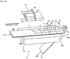
- Fig. 18 illustrates a state after generating nine pieces 116 of the workpiece by cutting the workpiece 106 with the cutting blade 101.
- the workpiece 106 is divided in the longitudinal direction by a transverse direction dividing line 112 extending in the width direction of the workpiece 106. Further, the workpiece 106 is divided in the width direction by a machine direction dividing line 113 extending in the longitudinal direction of the workpiece 106.
- the pieces 116 of the workpiece is formed in an area surrounded by the transverse direction dividing line 112 and the machine direction dividing line 113.
- nine pieces of the workpiece 116 are formed by three transverse direction dividing lines 112 and two machine direction dividing lines 113.
- the transverse direction dividing line 112 is formed by the transverse direction blade 102.
- the machine direction dividing line 113 is formed by the machine direction blade 103.
- the workpiece 106 is not cut at a line segment P located just below the transverse direction blade 102.
- the machine direction dividing lines 113 extend slightly beyond the line segment P.
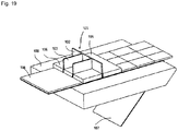
- the cutting blade 101 is pressed against the workpiece 106 from the state of Fig. 18 , as illustrated in Figs. 19 and 20 .
- the elastic member 105 is compressed and deformed by being pressed against the workpiece 106 by the fixing parts 104b (see Fig. 17 ).
- the elastic member 105 is compressed and deformed, so that the blade edges 102a, 103a are projected from the elastic member 105 and pressed against the workpiece 106 to cut the workpiece 106. Consequently, as illustrated in Fig. 21 , the transverse direction dividing line 112 is formed at a position of the line segment P by the transverse direction blade 102, and the machine direction dividing line 113 is extended by the machine direction blades 103.
- the cutting blade 101 is pressed against the workpiece 106 by a cylinder mechanism provided on the base part 104a, and the like. Further, a pressing force of the cutting blade 101 and a movement amount of the cutting blade 101 are set so that the cover material 107 is not cut by the cutting blade 101.
- the cutting blade 101 is pressed against the workpiece 106 while the machine direction blades 103 is parallel to the longitudinal direction of the workpiece 106.
- the machine direction blade 103 may be directed upstream or downstream of a moving direction of the workpiece 106 and may be preferably directed upstream. When there is a cutting failure, the pieces 116 of the workpiece on a downstream side from the cutting blade 101 are discarded. If the machine direction blade 103 is directed upstream, the number of the pieces 116 of the workpiece to be discarded may be smaller than when the machine direction blade 103 is directed downstream.
- Fig. 21 illustrates a state immediately after the cutting step is completed.
- the transverse direction dividing line 112 is formed at the position of the line segment P by the transverse direction blade 102, and the machine direction dividing lines 113 are extended by the machine direction blades 103. Consequently, three pieces of the workpiece 116 are newly generated.
- the pieces 116 of the workpiece are picked up while the pieces 116 of the workpiece in the second row C2 are pressed by a pressing unit 126. This can prevent the pieces 116 of the workpiece in the second row C2 from being picked up together.
- the pressing unit 126 may press only the pieces 116 of the workpiece in the second row C2 or may press the pieces 116 of the workpiece in a third and subsequent rows together.
- the pressing unit 126 comprises a plate part 126a coming into contact with the pieces 116 of the workpiece and a cylinder mechanism 126b for pressing the plate part 126a against the pieces 116 of the workpiece.
- the pieces 116 of the workpiece are picked up after the cutting step in the present embodiment, but the pieces 116 of the workpiece may be picked up after the moving step and before the cutting step.
- the pressing unit 126 is moved away from the pieces 116 of the workpiece after picking up the pieces 116 of the workpiece to allow the workpiece 106 and the pieces 116 of the workpiece to be moved.
- the pressing unit 126 is not illustrated in Figs. 18 , 19 , and 21 for convenience of illustration, the pressing unit 126 is disposed at a retracted position above the pieces 116 of the workpiece in the second row C2 while the pressing unit 126 is not pressing the pieces 116 of the workpiece.
- the workpiece 106 is moved in the longitudinal direction of the workpiece 106.
- the movement amount of the workpiece 106 is equal to (the length of the pieces 116 of the workpiece in the longitudinal direction) ⁇ (the number of the transverse direction blade 102).
- the number of the transverse direction blade 102 is one, and thus the movement amount of the workpiece 106 is equal to the length of the pieces 116 of the workpiece of the longitudinal direction.
- the pieces 116 of the workpiece can be manufactured continuously, as described above, and thus production efficiency is high.
- the entire workpiece 106 is divided to generate the pieces 116 of the workpiece, no cutoffs are generated.
- a second embodiment of the cutting blade is described with reference to Fig. 23 .
- the present embodiment is similar to the first embodiment, and the main difference is in the number of machine direction blades 103. The difference is mainly described below.
- a cutting blade 101 comprises four machine direction blades 103.
- a transverse direction blade 102 is divided by the machine direction blades 103 into an inner portion 102i and two outer portions 102o. Each of the portions 102i, 102o corresponds to one piece 116 of a workpiece.
- a function and configuration of two machine direction blades 103 on an inner side in the width direction among the four machine direction blades 103 are the same as in the first embodiment.
- Two machine direction blades 103 on an outer side in the width direction are not used for cutting the workpiece 106 when a length of the workpiece 106 in the width direction is equal to the total length of the portions 102i, 102o.
- the workpiece 106 in the width direction is larger than the total length of the portions 102i, 102o, the workpiece 106 is cut off by the two machine direction blades 103 on the outer side in the width direction so that the length of the workpiece 106 in the width direction is equal to the total length of the portions 102i, 102o.
- a third embodiment of the cutting blade is described with reference to Fig. 24 .
- the present embodiment is similar to the first embodiment, and the main difference is in the number of a machine direction blade 103. The difference is mainly described below.
- only one machine direction blade 103 is provided.
- a transverse direction blade 102 is thus divided by the machine direction blade 103 into two portions. Two pieces 116 of the workpiece are generated in one cycle of the cutting step and the moving step.
- a fourth embodiment of the cutting blade is described with reference to Fig. 25 .
- the present embodiment is similar to the first embodiment, and the main difference is in the number of transverse direction blades 102 and a length of machine direction blades 103. The difference is mainly described below.
- two transverse direction blades 102 are provide.
- a gap between the adjacent transverse direction blades 102 coincides with the length of the pieces 116 of the workpiece in the longitudinal direction.
- the length of the machine direction blades 103 is equal to or larger than twice the length of the pieces 116 of the workpiece in the longitudinal direction.
- the movement amount of the workpiece 106 in the moving step is equal to (the length of the pieces 116 of the workpiece in the longitudinal direction) ⁇ (the number of the transverse direction blade 102). Therefore, the movement amount of the workpiece 106 in the present embodiment is twice the length of the pieces 116 of the workpiece in the longitudinal direction. Six pieces 116 of the workpiece are generated in one cycle of the cutting step and the moving step.
- a fifth embodiment of the cutting blade is described with reference to Fig. 26 .
- the present embodiment is similar to the first embodiment, and the main difference is in a connection mode of the transverse direction blade 102 and the machine direction blades 103. The difference is mainly described below.
- one end of the machine direction blades 103 is connected to the transverse direction blade 102, and the other end is an open end.
- the machine direction blades 103 are connected to the transverse direction blade 102 at a portion other than end portions of the machine direction blades 103 (a central portion in the present embodiment), and both ends of the machine direction blades 103 are open ends. Even in such a configuration, the pieces 116 of the workpiece can be generated by repeating the cutting step and the moving step, as in the first embodiment.
Landscapes
- Engineering & Computer Science (AREA)
- Mechanical Engineering (AREA)
- Robotics (AREA)
- Life Sciences & Earth Sciences (AREA)
- Forests & Forestry (AREA)
- Labeling Devices (AREA)
- Folding Of Thin Sheet-Like Materials, Special Discharging Devices, And Others (AREA)
- Manipulator (AREA)
- Automobile Manufacture Line, Endless Track Vehicle, Trailer (AREA)
- Adhesive Tapes (AREA)
Abstract
Description
- The present invention relates to a robot system capable of clamping and sticking an adhesive member, such as a nonwoven fabric, on an object, such as an automobile interior member (for example, deck board) and further relates to a cutting blade used for cutting and forming the adhesive member.
- In recent years, labor saving by means of a robot has been promoted in factories.
PTL 1 discloses a technique for separating an attached material covering an adhesive part of a target object by means of an attached material separation unit with a needle unit. InPTL 1, the attached material on the target object approaches a sharp point of the needle unit at a predetermined approach angle to separate the attached material from the target object. - [PTL 1]
JP-A-2011-121770 - The technique disclosed in
PTL 1 requires some labor and time for a setting of a robot since a method of separating the attached material is complicated. - The present invention has been made in view of such a circumstance and is to provide a robot system capable of separating an adhesive member from a cover material and sticking the adhesive member on an object without a complicated setting.
- According to the present invention, provided is a robot system comprising a sticking mechanism configured to clamp and stick at least one adhesive member on an object and a supply mechanism capable of supplying the adhesive member, wherein: the sticking mechanism comprises a robot hand configured to clamp and release the adhesive member and a robot arm configured to move the robot hand; the supply mechanism is separate from the sticking mechanism, supplies the adhesive member in a state that the adhesive member is stuck to a cover material, and separates the cover material from the adhesive member by bending the cover material in a direction away from the adhesive member in order to enable the robot hand to clamp the adhesive member in a state that the cover material is separated from the adhesive member.
- In the present invention, the robot hand is configured to clamp the adhesive member while the adhesive member is separated from the cover material by bending the cover material, and thus it is possible to separate the adhesive member from the cover material and stick the adhesive member on the object without a complicated setting. In addition, since the supply mechanism is separate from the sticking mechanism, the robot hand can be downsized.
- Hereinafter, various embodiments of the present invention are exemplified. The embodiments below can be combined with each other.
- Preferably, the robot hand comprises at least one clamping unit configured to clamp and release the adhesive member.
- Preferably, the clamping unit comprises a clamping mechanism configured to clamp and release the adhesive member and a pressing mechanism configured to press the adhesive member against the object.
- Preferably, the clamping mechanism comprises a clamping base with a base surface and a first cylinder mechanism, wherein the first cylinder mechanism comprises a first cylinder base and a first rod, a projection length of the first rod from the first cylinder base being variable, and the clamping mechanism is configured to clamp the adhesive member between the base surface and the first rod.
- Preferably, the pressing mechanism comprises a rotary base rotatable relative to the clamping base and a pressing part provided on the rotary base and pressed against the adhesive member.
- Preferably, the rotary base is urged in a direction in which the pressing part is pressed against the adhesive member.
- Preferably, the pressing mechanism comprises a second cylinder mechanism, wherein the second cylinder mechanism comprises a second cylinder base and a second rod, a projection length of the second rod from the second cylinder base is variable, and the pressing mechanism is configured to adjust an angle of the rotary base relative to the clamping base by changing the projection length of the second rod.
- Preferably, the robot hand comprises a third cylinder mechanism, wherein the third cylinder mechanism comprises a third cylinder base and a third rod, a projection length of the third rod from the third cylinder base is variable, and the clamping unit is provided on the third rod.
- Preferably, the robot hand comprises a plurality of clamping units arranged in a line, wherein the supply mechanism is configured to supply a plurality of adhesive members arranged in a line, and the robot hand is configured to simultaneously clamp the plurality of adhesive members by the plurality of clamping units.
- Preferably, the robot hand is configured to cause the plurality of clamping units to project one by one so as to stick the plurality of adhesive members one by one to the object.
- Preferably, the adhesive member is a nonwoven fabric.
-
-
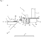
Fig. 1 is a front view illustrating arobot system 10 according to an embodiment of the present invention. -
Fig. 2 is an exploded perspective view of asupply mechanism 4. -
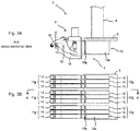
Figs. 3A and 3B illustrate asticking mechanism 3.Fig. 3B is a bottom view, andFig. 3A is a cross-sectional view taken along a line A-A inFig. 3B . -
Figs. 4A and 4B illustrate a state in which one of nineclamping units 11 is projected.Fig. 4B is a bottom view, andFig. 4A is a cross-sectional view taken along a line A-A inFig. 4B . -
Fig. 5 is an enlarged front view of theclamping units 11. -
Figs. 6A and 6B illustrate arotary base 16 and members fixed thereto inFig. 5 .Fig. 6A is a front view, andFig. 6B is a bottom view. -
Figs. 7A and 7B illustrate aclamping base 15 and members fixed thereto inFig. 5 .Fig. 7A is a front view, andFig. 7B is a bottom view. -
Fig. 8 is a front view illustrating a step of clamping and sticking anadhesive member 1 on anobject 2. -
Fig. 9 is a front view illustrating a step of clamping and sticking theadhesive member 1 on theobject 2. -
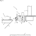
Fig. 10 is a front view illustrating a step of clamping and sticking theadhesive member 1 on theobject 2. -
Fig. 11 is a front view illustrating a step of clamping and sticking theadhesive member 1 on theobject 2. -
Fig. 12 is a front view illustrating a step of clamping and sticking theadhesive member 1 on theobject 2. -
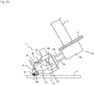
Fig. 13 is a front view illustrating a step of clamping and sticking theadhesive member 1 on theobject 2. -
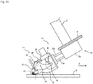
Fig. 14 is a front view illustrating a step of clamping and sticking theadhesive member 1 on theobject 2. -
Figs. 15A and 15B illustrate a cutting blade according to an embodiment of the present invention, showing acutting blade 101 of a first embodiment.Fig. 15A is a perspective view as viewed from an upper surface side, andFig. 15B is a perspective view as viewed from a bottom surface side. -
Fig. 16 is a perspective view illustrating a state in which thecutting blade 101 ofFigs. 15A and 15B is held by aholder 104. -
Fig. 17 is a perspective view illustrating a state in which anelastic member 105 is attached to theholder 104 ofFig. 16 . -
Fig. 18 is a perspective view illustrating a step of cutting aworkpiece 106 by means of thecutting blade 101 to generate a plurality of pieces of theworkpiece 116, showing a state before cutting theworkpiece 106 just below thecutting blade 101. Theholder 104 is omitted inFigs. 18 to 21 . -
Fig. 19 is a perspective view illustrating a state of cutting theworkpiece 106 by means of thecutting blade 101. -
Fig. 20 is a cross-sectional view ofFig. 19 , showing a cross section perpendicular to amachine direction blade 103. -
Fig. 21 is a perspective view illustrating a state immediately after cutting theworkpiece 106 just below thecutting blade 101. -
Fig. 22 is a perspective view illustrating a state in which thepieces 116 of the workpiece in a second row C2 are pressed by apressing unit 126. -
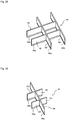
Fig. 23 is a perspective view as viewed from an upper surface side, illustrating acutting blade 101 of a second embodiment. -
Fig. 24 is a perspective view as viewed from an upper surface side, illustrating acutting blade 101 of a third embodiment. -
Fig. 25 is a perspective view as viewed from an upper surface side, illustrating acutting blade 101 of a fourth embodiment. -
Fig. 26 is a perspective view as viewed from an upper surface side, illustrating acutting blade 101 of a fifth embodiment. - Hereinafter, embodiments of the present invention are described. Various characteristics described in the embodiments below may be combined with each other. Further, each characteristic is independently inventive.
- As illustrated in
Fig. 1 , arobot system 10 of an embodiment of the present invention comprises asticking mechanism 3 configured to clamp and stick anadhesive member 1 on anobject 2 and asupply mechanism 4 capable of supplying anadhesive member 1. Thesticking mechanism 3 comprises arobot hand 5 configured to clamp and release theadhesive member 1 and arobot arm 6 configured to move therobot hand 5. - As illustrated in
Fig. 2 , theadhesive member 1 comprises anadhesive layer 1a on one surface and is configured to be stuck on theobject 2 by pressing theadhesive member 1 against theobject 2 while theadhesive layer 1a faces theobject 2. In the present embodiment, theadhesive member 1 is assumed to have a certain thickness. The thickness of theadhesive member 1 is, for example, 0.5 to 5 mm, and specifically, for example, 0.5, 1, 1.5, 2, 2.5, 3, 3.5, 4, 4.5, 5 mm and may be within a range between any two of the values exemplified herein. Theadhesive member 1 is stuck on theobject 2 for the purpose of preventing rattling or a vibration, noise reduction, or the like. A material thereof is not specifically limited, and may be, for example, a nonwoven fabric. It is difficult to pick up a nonwoven fabric by a vacuum suction mechanism due to air permeability thereof. As will be described below, thesticking mechanism 3 picks up theadhesive member 1 by clamping theadhesive member 1 with therobot hand 5. Therefore, it is possible to reliably pick up theadhesive member 1 even if theadhesive member 1 is made of a material having air permeability, such as a nonwoven fabric. Theobject 2 may be, for example, an automobile interior member, such as a deck board. - A
cover material 7 is stuck on a surface of theadhesive member 1 on a side of theadhesive layer 1a. Thecover material 7 has a function of covering theadhesive layer 1a. A paper or a sheet (so-called release paper) whose surface facing theadhesive layer 1a is subjected to easy peeling treatment is suitably used as thecover material 7. A large number ofadhesive members 1 are arranged in a grid pattern on thecover material 7. Threeadhesive members 1 are arranged in a line in a width direction (direction perpendicular to a longitudinal direction) of thecover material 7. A large number ofadhesive members 1 are continuously arranged in the longitudinal direction of thecover material 7. A tape member T configured by arranging a large number ofadhesive members 1 on thecover material 7 can be formed by sticking thecover material 7 on an adhesive layer of a large-area sheet and then making a cut (half-cut) in the large-area sheet so as to include the large number ofadhesive members 1. Theadhesive member 1 may be preferably rectangular or square in order to easily manufacture theadhesive member 1 by half cutting of the large-area sheet. A length of theadhesive member 1 in a longitudinal direction and a width direction may be preferably 1 to 5 cm, specifically, for example, 1, 2, 3, 4, 5 cm, or may be in a range between any two of the values exemplified herein. - The
supply mechanism 4 comprises a delivery roller R1, a take-up roller R2, and a bendingjig 8 provided therebetween. A tape member roll in which the tape member T is wound is mounted on the delivery roller R1, and the tape member T is supplied toward a bendingjig 8 associated with a rotation of the delivery roller R1 in a rewinding direction. Theadhesive member 1 is separated from thecover material 7 by the bendingjig 8 by bending thecover material 7 in a direction away from theadhesive member 1. Theadhesive member 1 in this state is clamped by therobot hand 5. Thecover material 7 is wound up associated with a rotation of the take-up roller R2. Rotation speeds of the delivery roller R1 and the take-up roller R2 are adjusted so as to maintain a state in which thecover material 7 is tensioned. Further, a tension roller for adjusting a tension applied to thecover material 7 is provided as needed between the delivery roller R1 and the take-up roller R2. - When the
adhesive member 1 has a large thickness as in a case of a nonwoven fabric, an outer diameter of the tape member roll tends to be large, and thus it is difficult to integrate thesupply mechanism 4 with thesticking mechanism 3. Therefore, when theadhesive member 1 has a large thickness as in a case of a nonwoven fabric, there is great technical significance in adopting a configuration in which thesupply mechanism 4 is separate from thesticking mechanism 3 as in the present embodiment. - The bending
jig 8 comprises atip 8a, anupper surface 8b, and an inclined surface 8c. Thetip 8a is provided to join with theupper surface 8b and the inclined surface 8c. Thecover material 7 is guided from the delivery roller R1 to the take-up roller R2 via theupper surface 8b, thetip 8a, and the inclined surface 8c in this order. An angle between theupper surface 8b and the inclined surface 8c at thetip 8a is not specifically limited, and may be for example, 15 to 75 degrees, preferably 30 to 60 degrees, and more preferably 40 to 50 degrees. This is because theadhesive member 1 can be easily separated from thecover material 7 in a case of such an angle. A radius of curvature of thetip 8a may be preferably equal to or less than a length L of theadhesive member 1 in a longitudinal direction, because theadhesive member 1 can be easily separated from thecover material 7 in such a case. The value of the radius of curvature of thetip 8a /length L may be, for example, 0.1 to 1, specifically, for example, 0.01, 0.05, 0.1, 0.2, 0.3, 0.4, 0.5, 0.6, 0.7, 0.8, 0.9, 1, or may be in a range between any two of the values exemplified herein. Further, the radius of curvature of thetip 8a may be, for example, 0.1 to 20 mm, preferably, 0.5 to 5 mm, specifically, for example, 0.1, 0.5, 1, 2, 3, 4, 5, 6, 7, 8, 9, 10, 11, 12, 13, 14, 15, 16, 17, 18, 19, 20 mm, or may be in a range between any two of the values exemplified herein. - A pressing means 26 is provided at a position facing the
upper surface 8b. As illustrated inFigs. 1 and2 , the pressing means 26 is provided so as to press theadhesive members 1 in the second row C2 while theadhesive members 1 in a top row C1 are being separated from thecover material 7, without pressing theadhesive members 1 in the top row C1. Therobot hand 5 of thesticking mechanism 3 clamps and pick up theadhesive members 1 in the top row C1 while the pressing means 26 presses theadhesive members 1 in the second row C2. This can prevent theadhesive members 1 in the second row C2 from being picked up together. The pressing means 26 may press only theadhesive members 1 in the second row C2 or may press theadhesive members 1 in a third and subsequent rows together. In one example, the pressing means 26 comprises aplate part 26a coming into contact with theadhesive members 1 and acylinder mechanism 26b for pressing theplate part 26a against theadhesive members 1. - The
sticking mechanism 3 comprises therobot hand 5 and therobot arm 6. Therobot arm 6 has a function of moving therobot hand 5, and specifically has a function of moving therobot hand 5, after therobot hand 5 clamps and picks up theadhesive member 1, to a position on theobject 2 where theadhesive member 1 is stuck. Therobot arm 6 has any number of shafts necessary to realize the above-described function and may preferably have six or more shafts. - The
robot hand 5 comprises a holdingplate 9. As illustrated inFigs. 3A and 3B , ninecylinder mechanisms 13 are fixed to the holdingplate 9. Acylinder mechanism group 13g includes threecylinder mechanisms 13 adjacent to each other so as to be aligned in a width direction. Therefore, threecylinder mechanism groups 13g are configured from the ninecylinder mechanisms 13 fixed to the holdingplate 9. There is a space between adjacentcylinder mechanism groups 13g. - Each of the
cylinder mechanisms 13 comprises acylinder base 13a and arod 13 b, a projection length of therod 13b from thecylinder base 13a being variable. A clampingunit 11 is attached to eachrod 13b. Aclamping unit group 11g includes three clampingunits 11 adjacent to each other so as to be arranged in a line in a width direction. Three clampingunit groups 11g are configured to correspond to the threecylinder mechanism groups 13g. There is a space between adjacent clamping unit groups. - Each of the clamping
units 11 is configured to clamp and release oneadhesive member 1. Therefore, theclamping unit group 11g including the three clampingunits 11 arranged in a line in a width direction is configured to simultaneously clamp threeadhesive members 1 arranged in a line in a width direction, as illustrated inFig. 2 . - When a first
clamping unit group 11g clamps and picks up threeadhesive members 1 in the top row C1, the delivery roller R1 and the take-up roller R2 rotate by a length of one row in a longitudinal direction of theadhesive member 1, and theadhesive members 1 in the second row C2 are delivered to a position of the top row C1, being separated from thecover material 7. Then, a secondclamping unit group 11g clamps and picks up the threeadhesive members 1 delivered to the position of the top row C1. Thereafter, a similar step is performed again, and a thirdclamping unit group 11g clamps and picks up threeadhesive members 1 delivered to the position of the top row C1. Through the above-mentioned step, nineadhesive members 1 are clamped and picked up by nine clampingunits 11 by three operations. - The nine
adhesive members 1 clamped by the nine clampingunits 11 are stuck one by one on theobject 2. Theadhesive layer 1a of theadhesive member 1 is exposed, and thus if the clampingunit 11 approaches theobject 2 to stick oneadhesive member 1 on theobject 2, anotheradhesive member 1 may be unintentionally stuck on theobject 2. In the present embodiment, oneclamping unit 11 is projected beyond theother clamping units 11, as illustrated inFigs. 4A and 4B , by operating thecylinder mechanism 13 to which theclamping unit 11 clamping theadhesive member 1 to be stuck on theobject 2 is attached and elongating a projection length of therod 13b. According to such a configuration, the projectingclamping unit 11 can be closer to theobject 2 than theother clamping units 11, and thus it is possible to stick only theadhesive member 1 to be stuck on theobject 2. That is, the nine clampingunits 11 can be projected one by one by operating the ninecylinder mechanisms 13 one by one, thereby allowing the nineadhesive members 1 to be stuck one by one. - As illustrated in
Figs. 5 to 7B , the clampingunit 11 comprises a clampingbase 15 and arotary base 16. Therotary base 16 is fixed at ashaft part 17 so as to be rotatable relative to the clamping base. 15 The clampingbase 15 is provided withcylinder mechanisms cylinder mechanism 18 comprises acylinder base 18a and arod 18b, a projection length of therod 18b from thecylinder base 18a being variable. Thecylinder mechanism 19 comprises acylinder base 19a and arod 19b, a projection length of therod 19b from thecylinder base 19a being variable. The cylinder bases 18a, 19a are fixed to the clampingbase 15. When the projection length of therod 18b is elongated by operating thecylinder mechanism 18, theadhesive member 1 can be clamped between therod 18b and abase surface 15a. Acontact part 27 coming into contact with theadhesive member 1 is attached to a tip of therod 18b. Thecontact part 27 may be preferably formed of a material softer than therod 18b. In such a case, thecontact part 27 comes in contact with theadhesive member 1 to prevent theadhesive member 1 from being damaged during clamping. Therod 19b is provided with acontact part 28 coming into contact with apositioning bolt 25. The clampingbase 15 is provided with an urgingmember support part 21 supporting an urgingmember 20. - As illustrated in
Figs. 6A and 6B , therotary base 16 is a plate-shaped member, and acontact block 22, asupport block 23, and apressing part 24 are provided between a pair ofrotary bases 16. Thesupport block 23 is provided with apositioning bolt 25. Thepressing part 24 may be, for example, a roller supported rotatably relative to therotary base 16. - As illustrated in
Fig. 5 , the urgingmember 20 is an elastic member, for example, a coil spring, and is disposed between the urgingmember support part 21 and thecontact block 22 in a state of being contracted compared to a natural length (note thatFigs. 7A and 7B illustrate a state in which the urgingmember 20 is in a natural length). Therefore, the urgingmember 20 has a restoring force to regain the natural length, and therotary base 16 is urged counterclockwise by the restoring force. When therotary base 16 rotates counterclockwise, thepressing part 24 is pressed against theadhesive member 1 clamped between thecontact part 27 and thebase surface 15a. A "pressing direction" in Claims is thus counterclockwise in the present embodiment. - When the
rotary base 16 is urged in a counterclockwise direction, thepositioning bolt 25 is pressed against thecontact part 28. Since thecontact part 28 is fixed to therod 19b, thecontact part 28 does not move unless therod 19b is retracted (unless the projection length of therod 19b is shortened). An angle of therotary base 16 relative to the clampingbase 15 is thus maintained in a state illustrated inFig. 5 unless therod 19b is retracted. Meanwhile, when therod 19b is retracted, therotary base 16 is rotated counterclockwise by the restoring force of the urgingmember 20, so that thepressing part 24 is pressed against theadhesive member 1 clamped between thecontact part 27 and thebase surface 15a (seeFig. 13 ). Thus, an angle of therotary base 16 relative to the clampingbase 15 can be adjusted by changing the projection length of therod 19b. - As described above, a clamping mechanism configured to clamp and release the
adhesive member 1 is realized with the clampingbase 15 and thecylinder mechanism 18. Further, a pressing mechanism configured to press theadhesive member 1 against theobject 2 is realized with therotary base 16, thepressing part 24, the urgingmember 20, thecylinder mechanism 19 and the like. - Next, a method of sticking the
adhesive member 1 on theobject 2 is described with reference toFigs. 8 to 14 . - (1) First, as illustrated in
Fig. 8 , the threeadhesive members 1 in the top row C1 are separated from thecover material 7. - (2) Then, as illustrated in
Fig. 8 , theadhesive members 1 in the second row C2 are pressed by the pressingmeans 26. - (3) Then, as illustrated in
Fig. 8 , the clampingunit 11 to clamp theadhesive member 1 is projected beyond theother clamping units 11 by operating thecylinder mechanism 13 to which theclamping unit 11 to clamp theadhesive member 1 is attached to elongate the projection length of therod 13b (seeFigs. 4A and 4B ). Here, in order to simultaneously clamp the threeadhesive members 1 in the top row C1 by theclamping unit group 11g including the three clampingunits 11, the projection length of each of therods 13b of thecylinder mechanism group 13g to which theclamping unit group 11g is attached is elongated. In such a state, theadhesive member 1 is disposed between thebase surface 15a and thecontact part 27. Theadhesive layer 1a of theadhesive member 1 may be contacted with thebase surface 15a at this time. - (4) Then, as illustrated in
Fig. 9 , theadhesive member 1 is clamped between thebase surface 15a and thecontact part 27 by increasing the projection length of therod 18b. The threeclamping units 11 included in theclamping unit group 11g simultaneously clamp the threeadhesive members 1 in the top row C1 at this time. - (5) Then, as illustrated in
Fig. 10 , theadhesive members 1 are completely separated from the tape member T by moving the clampingunits 11 with therobot arm 6 and reducing the projection length of therod 13b. - (6) The nine
adhesive members 1 are clamped by the nine clampingunits 11 by performing the steps above with the threeclamping unit groups 11g. - (7) Then, as illustrated in
Fig. 11 , therobot hand 5 is inclined so that theadhesive member 1 approaches theobject 2, and thecylinder mechanism 13 to which theclamping unit 11 holding theadhesive member 1 to be stuck is attached is operated to increase the projection length of therod 13b. Consequently, oneclamping unit 11 is projected beyond the other clamping units 11 (seeFigs. 4A and 4B ). - (8) Then, as illustrated in
Fig. 12 , the projection length of therod 19b (seeFig. 5 ) is reduced, so that therotary base 16 is rotated counterclockwise by the restoring force of the urgingmember 20 to contact thepressing part 24 with theadhesive member 1. Thecontact part 28 comes in contact with thepositioning bolt 25 in a state ofFig. 12 . The projection length of therod 19b is set so that thepressing part 24 is contacted with theadhesive member 1 but the restoring force of the urgingmember 20 is not applied to theadhesive member 1. - (9) Then, as illustrated in
Fig. 13 , theadhesive member 1 is contacted with theobject 2. In a state ofFig. 13 , thecontact part 28 and thepositioning bolt 25 are not in contact with each other, and the restoring force of the urgingmember 20 is applied to theadhesive member 1 via thepressing part 24. - (10) Then, as illustrated in
Figs. 13 and14 , theadhesive member 1 is released from a clamped state by thebase surface 15a and thecontact part 27 by reducing the projection length of therod 18b. Then, as illustrated with an arrow X inFig. 14 , theadhesive member 1 is stuck on theobject 2 by moving the clampingunit 11 along a surface of theobject 2. - (11) Then, the
adhesive member 1 can be stuck to nine parts of theobject 2 by repeatedly performing the steps (7) to (10) for all theadhesive members 1. - The present invention may be also practiced in the following aspects.
- The number of the
adhesive member 1 provided in each row of the tape member T may be one, two, or four or more, and preferably more than one. - The number of the clamping
unit 11 included in theclamping unit group 11g may be one, two, or four or more, and preferably more than one. - The number of the
clamping unit group 11g may be one, two, or four or more, and preferably more than one. - Each operation included in the steps (7) to (10) may be switched in order as appropriate.
- The
pressing part 24 may be brought into contact with theadhesive member 1 after bringing theadhesive member 1 into contact with theobject 2. - The projection length of the
rod 13b may be increased after bringing thepressing part 24 into contact with theadhesive member 1. - The
robot hand 5 may be inclined after bringing thepressing part 24 into contact with theadhesive member 1. - The
adhesive member 1 used in the above-mentioned robot system can be formed by sticking thecover material 7 on an adhesive layer of a large-area sheet and then making a cut (half-cut) in the large-area sheet to cut the large-area sheet into a large number of theadhesive members 1. - It is necessary to use a cutting blade for making a cut in the large-area sheet. As a cutting technique using the cutting blade, there is a technique for cutting a flat material into a rectangular shape by press punching using a flat material cutting blade comprising a holding plate on which a slit for inserting the cutting blade is formed such that an arrangement shape corresponds to a shape to be obtained by cutting and the cutting blade inserted into and held by the slit.
- However, it is necessary in the technique to process flat materials one by one, and thus low production efficiency is problematic.
- The present invention has been made in view of such a circumstance and is to provide a cutting blade capable of efficiently performing a process of cutting a workpiece to generate a plurality of pieces of the workpiece.
- According to the present embodiment, provided is a cutting blade for cutting a workpiece by pressing a blade edge against the workpiece to generate a plurality of pieces of the workpiece, wherein the cutting blade comprises a transverse direction blade and a machine direction blade; the machine direction blade is connected to the transverse direction blade so as to divide the transverse direction blade into a plurality of portions; and at least one end of the machine direction blade is an open end.
- The cutting blade of the present embodiment is characterized in that at least one end of the machine direction blade is an open end. When such a cutting blade is used, it is possible to efficiently produce a large number of pieces of the workpiece arranged in a grid pattern by alternately cutting the workpiece and moving the workpiece. In addition, no offcuts occur between two adjacent pieces of the workpiece. Thus, less material is wasted, and time required for processing the offcuts can be reduced.
- Hereinafter, various embodiments are exemplified. The embodiments below can be combined with each other.
- Preferably, the transverse direction blade and the machine direction blade are orthogonal to each other.
- Preferably, a blade edge of the machine direction blade is connected to a blade edge of the transverse direction blade.
- Preferably, the cutting blade comprises a plurality of machine direction blades.
- According to another aspect of the present embodiment, provided is a method of manufacturing pieces of a band-shaped workpiece comprising a cutting step and a moving step, wherein, in the cutting step, a blade edge of the above-mentioned cutting blade is pressed against the workpiece to cut the workpiece; in the moving step, the workpiece is moved in a longitudinal direction of the workpiece; the cutting step and the moving step are performed alternately; and every time the cutting step is performed, the workpiece is cut to generate a plurality of pieces of the workpiece.
- Preferably, the cutting blade is pressed against the workpiece while the machine direction blade is parallel to the longitudinal direction.
- Preferably, a movement amount of the workpiece in the moving step is equal to (length of the pieces of the workpiece in the longitudinal direction)×(number of the transverse direction blade).
- Preferably, the workpiece is supplied by a roll-to-roll method.
- Preferably, the cutting blade is disposed so that the machine direction blade is directed upstream of a moving direction of the workpiece.
- Preferably, the cutting blade is held by a holder, and the cutting step is performed such that an elastic member provided between the holder and the workpiece is compressed and deformed.
- Preferably, the workpiece comprises an adhesive layer on one surface; a cover material is provided on a side of the adhesive layer; and the cutting step is performed such that the cover material is not cut by the cutting blade.
- A
cutting blade 101 of a first embodiment and a manufacturing method of pieces of aworkpiece 116 by means of thecutting blade 101 are described with reference toFigs. 15A to 21 . - As illustrated
Figs. 15A, 15B , and18 , thecutting blade 1 is used for cutting aworkpiece 106 by pressingblade edges workpiece 106 to generate a plurality ofpieces 116 of the workpiece. - As illustrated in
Fig. 15A , thecutting blade 101 comprises atransverse direction blade 102 and twomachine direction blades 103. Thetransverse direction blade 102 comprises ablade edge 102a. Themachine direction blade 103 comprises ablade edge 103a. The blade edges 102a, 103a are both linear. As illustrated inFig. 15B , theblade edge 103a of themachine direction blade 103 is connected to theblade edge 102a of thetransverse direction blade 102. Theblade edge 102a and theblade edge 103a are thus continuously connected without a gap, and the problem that theworkpiece 106 is not cut between theblade edge 102a and theblade edge 103a does not occur. - In the following description, a direction in which the
transverse direction blade 102 extends is referred to as a width direction, and a direction in which themachine direction blade 103 extends is referred to as a longitudinal direction. Further, as described later, theworkpiece 106 and thepieces 116 of the workpiece are moved in a direction in which themachine direction blade 103 extends. Therefore, a moving direction of theworkpiece 106 and thepieces 116 of the workpiece coincides with the longitudinal direction. - The
transverse direction blade 102 and themachine direction blade 103 are orthogonal to each other. Themachine direction blade 103 is connected to thetransverse direction blade 102 so as to divide thetransverse direction blade 102 into a plurality of portions. The twomachine direction blades 103 are provided, and thetransverse direction blade 102 is divided into three portions by the twomachine direction blades 103. That is, thetransverse direction blade 102 is divided into N+1 portions by Nmachine direction blades 103. N is a natural number of 1 or more. Thetransverse direction blade 102 is divided into aninner portion 102i and two outer portions 102o. Theinner portion 102i and the two outer portions 102o respectively correspond to onepiece 116 of the workpiece. A length of theinner portion 102i is equal to a length of thepieces 116 of the workpiece in the width direction. A length of the outer portions 102o is equal to or more than the length of thepieces 116 of the workpiece in the width direction. - The two
machine direction blades 103 extend in parallel. A gap between the blade edges 103a of the twomachine direction blades 103 coincides with the length of thepieces 116 of the workpiece in the width direction. A length of themachine direction blade 103 is equal to or more than a length of thepieces 116 of the workpiece in a moving direction. In order to reliably divide theworkpiece 106, the length of themachine direction blade 103 may be preferably longer than the length of thepieces 116 of the workpiece in the moving direction. - The
machine direction blade 103 is connected to thetransverse direction blade 102 at one end, and the other end is an open end. Themachine direction blade 103 is not connected to thetransverse direction blade 102 at the open end and is not connected to any other member. Further, the open ends of a pair of themachine direction blades 103 are not connected to each other. Such a configuration suppresses the generation of offcuts in the longitudinal direction of theworkpiece 106. - As illustrated in
Fig. 16 , thecutting blade 101 may be used in a state of being held by aholder 104. Theholder 104 comprises abase part 104a and a plurality of fixingparts 104b. Thetransverse direction blade 102 and themachine direction blades 103 are held between two adjacent fixingparts 104b. - As illustrated in
Fig. 17 , each of the fixingparts 104b comprises a facing surface 104b1 facing theworkpiece 106. Anelastic member 105 is mounted on the facing surface 104b1. Theelastic member 105 is compressed and deformed while thecutting blade 101 is pressed against theworkpiece 106, and restores its original shape when thecutting blade 101 is separated from theworkpiece 106. Adhesion of theworkpiece 106 and thepieces 116 of the workpiece to thecutting blade 101 is suppressed by a restoring force at this time. If theworkpiece 106 and thepieces 116 of the workpiece comprise anadhesive layer 136, there is great technical significance in providing anelastic member 105 since theadhesive layer 136 can easily adhere to thecutting blade 101 when theworkpiece 106 is cut. Theelastic member 105 may be, for example, a buffer member or a spring. - Assuming that a thickness of the
elastic member 105 in a non-compressed state is T, a projection length of thecutting blade 101 from the facing surface 104b1 is P, and a thickness of theworkpiece 106 is WT, it is preferable to satisfy a×T+WT > P (a<1), and more preferably to satisfy a×T > P (a<1). Since theelastic member 105 is compressed and deformed in this case when theworkpiece 106 is cut by thecutting blade 101, the adhesion of theworkpiece 106 and thepieces 116 of the workpiece to thecutting blade 101 is suppressed by the restoring force. a may be, for example, 0.3 to 0.9, specifically, for example, 0.3, 0.4, 0.5, 0.6, 0.7, 0.8, 0.9, or may be in a range between any two of the values exemplified herein. a is appropriately set so as to generate a restoring force needed in accordance with a material of theelastic member 105. - Next, a method of cutting the
workpiece 106 by means of thecutting blade 101 to generate the plurality ofpieces 116 of the workpiece is described. -
Fig. 18 is a perspective view illustrating a basic configuration of a cutting device for cutting theworkpiece 106. Theworkpiece 106 is assumed to have a certain thickness. The thickness of theworkpiece 106 and thepieces 116 of the workpiece may be, for example, 0.5 to 5 mm, specifically, for example, 0.5, 1, 1.5, 2, 2.5, 3, 3.5, 4, 4.5, 5 mm, or may be in a range between any two of the values exemplified herein.. Thepieces 116 of the workpiece is stuck on an object for the purpose of preventing rattling or a vibration, noise reduction, or the like. The material thereof is not specifically limited, and may be, for example, a nonwoven fabric. The object may be, for example, an automobile interior member, such as a deck board. - The
workpiece 106 is band-shaped. A length of theworkpiece 106 in the width direction may be preferably N times (N is a natural number of 2 or more) the length of thepieces 116 of the workpiece in the width direction. N may be preferably the number of themachine direction blade 103 + 1. In the present embodiment, the number of themachine direction blades 103 is two, and the length of theworkpiece 106 in the width direction is three times the length of thepieces 116 of the workpiece in the width direction. Thepieces 116 of the workpiece are rectangular or square. A length of thepieces 116 of the workpiece in the longitudinal direction and in the width direction each may be preferably 1 to 5 cm, specifically, for example, 1, 2, 3, 4, 5 cm, or may be in a range between any two of the values exemplified herein. - The
workpiece 106 and thepieces 116 of the workpiece comprises anadhesive layer 136 on one surface. Acover material 107 is stuck on a surface on a side of theadhesive layer 136. Thecover material 107 has a function of covering theadhesive layer 136. A paper or a sheet (so-called release paper) whose surface facing theadhesive layer 136 is subjected to easy peeling treatment is suitably used as thecover material 107. Since thecover material 107 is not cut when theworkpiece 106 is cut, thepieces 116 of the workpiece generated by cutting theworkpiece 106 are arranged in a grid pattern on thecover material 107. - The
workpiece 106 is supplied by a roll-to-rolltype supply mechanism 114. Thesupply mechanism 114 comprises a delivery roller R101, a take-up roller R102, and a receivingjig 108 provided therebetween. A workpiece roll in which theworkpiece 106 is wound is mounted on the delivery roller R101, and theworkpiece 106 is supplied toward the receivingjig 108 associated with a rotation of the delivery roller R101 in a rewinding direction. Theworkpiece 106 is cut by thecutting blade 101 at the receivingjig 108 to generate the plurality ofpieces 116 of the workpiece. Then, thepieces 116 of the workpiece are separated from thecover material 107 by bending, at atip 108a of the receivingjig 108, thecover material 107 in a direction away from thepieces 116 of the workpiece. In this state, thepieces 116 of the workpiece is clamped and picked up by the robot hand or the like. Thecover material 107 is taken up associated with a rotation of the take-up roller R102. Rotational speeds of the delivery roller R101 and the take-up roller R102 are adjusted so that thecover material 107 is maintained in a tensioned state. Further, a tension roller for adjusting a tension applied to thecover material 107 is provided as needed between the delivery roller R101 and the take-up roller R102. - The receiving
jig 108 comprises thetip 108a, anupper surface 108b, and aninclined surface 108c. Thetip 108a is provided to be connected to theupper surface 108b and theinclined surface 108c. Thecover material 107 is guided from the delivery roller R101 to the take-up roller R102 via theupper surface 108b, thetip 108a, and theinclined surface 108c in this order. An angle between theupper surface 108b and theinclined surface 108c at thetip 108a is not specifically limited, and may be for example, 15 to 75 degrees, preferably 30 to 60 degrees, and more preferably 40 to 50 degrees. This is because thepieces 116 of the workpiece can be easily separated from thecover material 107 in a case of such an angle. A radius of curvature of thetip 108a may be preferably equal to or less than a length L of thepieces 116 of the workpiece in the longitudinal direction, because thepieces 116 of the workpiece can be easily separated from thecover material 107 in such a case. -
Fig. 18 illustrates a state after generating ninepieces 116 of the workpiece by cutting theworkpiece 106 with thecutting blade 101. Theworkpiece 106 is divided in the longitudinal direction by a transversedirection dividing line 112 extending in the width direction of theworkpiece 106. Further, theworkpiece 106 is divided in the width direction by a machinedirection dividing line 113 extending in the longitudinal direction of theworkpiece 106. As a result of dividing theworkpiece 106 by the transversedirection dividing line 112 and the machinedirection dividing line 113, thepieces 116 of the workpiece is formed in an area surrounded by the transversedirection dividing line 112 and the machinedirection dividing line 113. In a state ofFig. 18 , nine pieces of theworkpiece 116 are formed by three transversedirection dividing lines 112 and two machinedirection dividing lines 113. The transversedirection dividing line 112 is formed by thetransverse direction blade 102. The machinedirection dividing line 113 is formed by themachine direction blade 103. - In the state of
Fig. 18 , theworkpiece 106 is not cut at a line segment P located just below thetransverse direction blade 102. The machinedirection dividing lines 113 extend slightly beyond the line segment P. - In the cutting step, the
cutting blade 101 is pressed against theworkpiece 106 from the state ofFig. 18 , as illustrated inFigs. 19 and20 . At this time, theelastic member 105 is compressed and deformed by being pressed against theworkpiece 106 by the fixingparts 104b (seeFig. 17 ). Theelastic member 105 is compressed and deformed, so that the blade edges 102a, 103a are projected from theelastic member 105 and pressed against theworkpiece 106 to cut theworkpiece 106. Consequently, as illustrated inFig. 21 , the transversedirection dividing line 112 is formed at a position of the line segment P by thetransverse direction blade 102, and the machinedirection dividing line 113 is extended by themachine direction blades 103. Thecutting blade 101 is pressed against theworkpiece 106 by a cylinder mechanism provided on thebase part 104a, and the like. Further, a pressing force of thecutting blade 101 and a movement amount of thecutting blade 101 are set so that thecover material 107 is not cut by thecutting blade 101. - The
cutting blade 101 is pressed against theworkpiece 106 while themachine direction blades 103 is parallel to the longitudinal direction of theworkpiece 106. Themachine direction blade 103 may be directed upstream or downstream of a moving direction of theworkpiece 106 and may be preferably directed upstream. When there is a cutting failure, thepieces 116 of the workpiece on a downstream side from thecutting blade 101 are discarded. If themachine direction blade 103 is directed upstream, the number of thepieces 116 of the workpiece to be discarded may be smaller than when themachine direction blade 103 is directed downstream. - When the
cutting blade 101 moves up from a state ofFigs. 19 and20 , theelastic member 105 expands to restore the original shape. At this time, the adhesion of theworkpiece 106 and thepieces 116 of the workpiece to thecutting blade 101 is suppressed by the restoring force. -
Fig. 21 illustrates a state immediately after the cutting step is completed. The transversedirection dividing line 112 is formed at the position of the line segment P by thetransverse direction blade 102, and the machinedirection dividing lines 113 are extended by themachine direction blades 103. Consequently, three pieces of theworkpiece 116 are newly generated. - Then, three
pieces 116 of the workpiece in the top row C1 protruding from the receivingjig 108 are clamped and picked up by the robot hand, and then the moving step is performed. - The
pieces 116 of the workpiece are picked up while thepieces 116 of the workpiece in the second row C2 are pressed by apressing unit 126. This can prevent thepieces 116 of the workpiece in the second row C2 from being picked up together. Thepressing unit 126 may press only thepieces 116 of the workpiece in the second row C2 or may press thepieces 116 of the workpiece in a third and subsequent rows together. In one example, thepressing unit 126 comprises aplate part 126a coming into contact with thepieces 116 of the workpiece and acylinder mechanism 126b for pressing theplate part 126a against thepieces 116 of the workpiece. In this regard, thepieces 116 of the workpiece are picked up after the cutting step in the present embodiment, but thepieces 116 of the workpiece may be picked up after the moving step and before the cutting step. Thepressing unit 126 is moved away from thepieces 116 of the workpiece after picking up thepieces 116 of the workpiece to allow theworkpiece 106 and thepieces 116 of the workpiece to be moved. Although thepressing unit 126 is not illustrated inFigs. 18 ,19 , and21 for convenience of illustration, thepressing unit 126 is disposed at a retracted position above thepieces 116 of the workpiece in the second row C2 while thepressing unit 126 is not pressing thepieces 116 of the workpiece. - In the moving step, the
workpiece 106 is moved in the longitudinal direction of theworkpiece 106. The movement amount of theworkpiece 106 is equal to (the length of thepieces 116 of the workpiece in the longitudinal direction) × (the number of the transverse direction blade 102). In the present embodiment, the number of thetransverse direction blade 102 is one, and thus the movement amount of theworkpiece 106 is equal to the length of thepieces 116 of the workpiece of the longitudinal direction. - Thereafter, by repeating the cutting step and the moving step, three
pieces 116 of the workpiece are newly formed each time the cutting process is performed. - According to the present embodiment, the
pieces 116 of the workpiece can be manufactured continuously, as described above, and thus production efficiency is high. In addition, since theentire workpiece 106 is divided to generate thepieces 116 of the workpiece, no cutoffs are generated. - A second embodiment of the cutting blade is described with reference to
Fig. 23 . The present embodiment is similar to the first embodiment, and the main difference is in the number ofmachine direction blades 103. The difference is mainly described below. - In the present embodiment, a
cutting blade 101 comprises fourmachine direction blades 103. Atransverse direction blade 102 is divided by themachine direction blades 103 into aninner portion 102i and two outer portions 102o. Each of theportions 102i, 102o corresponds to onepiece 116 of a workpiece. - A function and configuration of two
machine direction blades 103 on an inner side in the width direction among the fourmachine direction blades 103 are the same as in the first embodiment. Twomachine direction blades 103 on an outer side in the width direction are not used for cutting theworkpiece 106 when a length of theworkpiece 106 in the width direction is equal to the total length of theportions 102i, 102o. On the other hand, when the length of theworkpiece 106 in the width direction is larger than the total length of theportions 102i, 102o, theworkpiece 106 is cut off by the twomachine direction blades 103 on the outer side in the width direction so that the length of theworkpiece 106 in the width direction is equal to the total length of theportions 102i, 102o. - A third embodiment of the cutting blade is described with reference to
Fig. 24 . The present embodiment is similar to the first embodiment, and the main difference is in the number of amachine direction blade 103. The difference is mainly described below. - In the present embodiment, only one
machine direction blade 103 is provided. Atransverse direction blade 102 is thus divided by themachine direction blade 103 into two portions. Twopieces 116 of the workpiece are generated in one cycle of the cutting step and the moving step. - A fourth embodiment of the cutting blade is described with reference to
Fig. 25 . The present embodiment is similar to the first embodiment, and the main difference is in the number oftransverse direction blades 102 and a length ofmachine direction blades 103. The difference is mainly described below. - In the present embodiment, two
transverse direction blades 102 are provide. A gap between the adjacenttransverse direction blades 102 coincides with the length of thepieces 116 of the workpiece in the longitudinal direction. The length of themachine direction blades 103 is equal to or larger than twice the length of thepieces 116 of the workpiece in the longitudinal direction. - In the present embodiment, the movement amount of the
workpiece 106 in the moving step is equal to (the length of thepieces 116 of the workpiece in the longitudinal direction)×(the number of the transverse direction blade 102). Therefore, the movement amount of theworkpiece 106 in the present embodiment is twice the length of thepieces 116 of the workpiece in the longitudinal direction. Sixpieces 116 of the workpiece are generated in one cycle of the cutting step and the moving step. - A fifth embodiment of the cutting blade is described with reference to
Fig. 26 . The present embodiment is similar to the first embodiment, and the main difference is in a connection mode of thetransverse direction blade 102 and themachine direction blades 103. The difference is mainly described below. - In the first embodiment, one end of the
machine direction blades 103 is connected to thetransverse direction blade 102, and the other end is an open end. In the present embodiment, themachine direction blades 103 are connected to thetransverse direction blade 102 at a portion other than end portions of the machine direction blades 103 (a central portion in the present embodiment), and both ends of themachine direction blades 103 are open ends. Even in such a configuration, thepieces 116 of the workpiece can be generated by repeating the cutting step and the moving step, as in the first embodiment. - 1: adhesive member, 1a: adhesive layer, 2: object, 3: sticking mechanism, 4: supply mechanism, 5: robot hand, 6: robot arm, 7: cover material, 8: bending jig, 8a: tip, 8b: upper surface, 8c: inclined surface, 9: holding plate, 10: robot system, 11: clamping unit, 11g: clamping unit group, 13: cylinder mechanism, 13a: cylinder base, 13b: rod, 13g: cylinder mechanism group, 15: clamping base, 15a: base surface, 16: rotary base, 17: shaft part, 18: cylinder mechanism, 18a: cylinder base, 18b: rod, 19: cylinder mechanism, 19a: cylinder base, 19b: rod, 20: urging member, 21: support part of urging member, 22: contact block, 23: support block, 24: pressing part, 25: positioning bolt, 26: pressing means, 26a: plate part, 26b: cylinder mechanism, 27: contact part, 28: contact part, R1: delivery roller, R2: take-up roller, T: tape member, 101: cutting blade, 102: transverse direction blade, 102a: blade edge, 102i: inner portion, 102o: outer portion, 103: machine direction blade, 103a: blade edge, 104: holder, 104a: base part, 104b: fixing part, 104b1: facing surface, 105: elastic member 106: workpiece, 107: cover material, 108: receiving jig, 108a: tip, 108b: upper surface, 108c: inclined surface, 112: transverse direction dividing line, 113: machine direction dividing line, 114: supply mechanism, 116: pieces of workpiece, 126: pressing unit, 126a: plate part, 126b: cylinder mechanism, 136: adhesive layer, P: line segment, R101: delivery roller, R102: take-up roller
Claims (22)
- A robot system comprising a sticking mechanism configured to clamp and stick at least one adhesive member on an object and a supply mechanism capable of supplying the adhesive member, wherein:the sticking mechanism comprises a robot hand configured to clamp and release the adhesive member and a robot arm configured to move the robot hand;the supply mechanism is separate from the sticking mechanism, supplies the adhesive member in a state that the adhesive member is stuck to a cover material, and separates the cover material from the adhesive member by bending the cover material in a direction away from the adhesive member in order to enable the robot hand to clamp the adhesive member in a state that the cover material is separated from the adhesive member.
- The system of Claim 1, wherein the robot hand comprises at least one clamping unit configured to clamp and release the adhesive member.
- The system of Claim 2, wherein the clamping unit comprises a clamping mechanism configured to clamp and release the adhesive member and a pressing mechanism configured to press the adhesive member against the object.
- The system of Claim 3, wherein:the clamping mechanism comprises a clamping base with a base surface and a first cylinder mechanism;the first cylinder mechanism comprises a first cylinder base and a first rod, a projection length of the first rod from the first cylinder base being variable; andthe clamping mechanism is configured to clamp the adhesive member between the base surface and the first rod.
- The system of Claim 4, wherein the pressing mechanism has a rotary base rotatable relative to the clamping base and a pressing part provided on the rotary base and pressed against the adhesive member.
- The system of Clam 5, wherein the rotary base is urged in a direction in which the pressing part is pressed against the adhesive member.
- The system of Claim 6, wherein:the pressing mechanism comprises a second cylinder mechanism;the second cylinder mechanism comprises a second cylinder base and a second rod, a projection length of the second rod from the second cylinder base is variable; andthe pressing mechanism is configured to adjust an angle of the rotary base relative to the clamping base by changing the projection length of the second rod.
- The system of any one of Claims 2 to 7, wherein:the robot hand comprises a third cylinder mechanism;the third cylinder mechanism comprises a third cylinder base and a third rod, a projection length of the third rod from the third cylinder base is variable; andthe clamping unit is provided on the third rod.
- The system of any one of Claims 2 to 8, wherein:the at least one clamping unit comprises a plurality of clamping units;the at least one adhesive member comprises a plurality of adhesive members;the robot hand comprises the plurality of clamping units arranged in a line;the supply mechanism is configured to supply the plurality of adhesive members arranged in a line;the robot hand is configured to simultaneously clamp the plurality of adhesive members by the plurality of clamping units.
- The system of Claim 9, wherein the robot hand is configured to cause the plurality of clamping units to project one by one so as to stick the plurality of adhesive members one by one to the object.
- The system of any one of Claims 1 to 10, wherein the adhesive member is a nonwoven fabric.
- A cutting blade for cutting a workpiece by pressing a blade edge against the workpiece to generate a plurality of pieces of the workpiece, wherein:the cutting blade comprises a transverse direction blade and at least one machine direction blade;the machine direction blade is connected to the transverse direction blade so as to divide the transverse direction blade into a plurality of portions; andat least one end of the machine direction blade is an open end.
- The cutting blade of Claim 12, wherein the transverse direction blade and the machine direction blade are orthogonal to each other.
- The cutting blade of Claim 12 or 13, wherein a blade edge of the machine direction blade is connected to a blade edge of the transverse direction blade.
- The cutting blade of any one of Claims 12 to 14, wherein the at least one machine direction blade comprises a plurality of machine direction blades.
- A method of manufacturing pieces of a band-shaped workpiece comprising a cutting step and a moving step, wherein:in the cutting step, a blade edge of the cutting blade according to any one of Claims 12 to 15 is pressed against the workpiece to cut the workpiece;in the moving step, the workpiece is moved in a longitudinal direction of the workpiece;the cutting step and the moving step are performed alternately; andevery time the cutting step is performed, the workpiece is cut to generate a plurality of pieces of the workpiece.
- The method of Claim 16, wherein the cutting blade is pressed against the workpiece while the machine direction blade is parallel to the longitudinal direction.
- The method of Claim 16 or 17, wherein a movement amount of the workpiece in the moving step is equal to (length of the pieces of the workpiece in the longitudinal direction)×(number of the transverse direction blade).
- The method of any one of Claims 16 to 18, wherein the workpiece is supplied by a roll-to-roll method.
- The method of any one of Claims 16 to 19, wherein the cutting blade is disposed such that the machine direction blade is directed upstream of a moving direction of the workpiece.
- The method of any one of Claims 16 to 20, wherein:the cutting blade is held by a holder, andthe cutting step is performed such that an elastic member provided between the holder and the workpiece is compressed and deformed.
- The method of any one of Claims 16 to 21, wherein:the workpiece comprises an adhesive layer on one surface;a cover material is provided on a side of the adhesive layer; andthe cutting step is performed such that the cover material is not cut by the cutting blade.
Applications Claiming Priority (3)
| Application Number | Priority Date | Filing Date | Title |
|---|---|---|---|
| JP2016243135A JP7089340B2 (en) | 2016-12-15 | 2016-12-15 | Robot system |
| JP2017033362A JP7037888B2 (en) | 2017-02-24 | 2017-02-24 | Work piece manufacturing method |
| PCT/JP2017/044990 WO2018110677A1 (en) | 2016-12-15 | 2017-12-14 | Robot system and cutting blade |
Publications (3)
| Publication Number | Publication Date |
|---|---|
| EP3556670A1 true EP3556670A1 (en) | 2019-10-23 |
| EP3556670A4 EP3556670A4 (en) | 2020-04-15 |
| EP3556670B1 EP3556670B1 (en) | 2022-05-18 |
Family
ID=62558901
Family Applications (1)
| Application Number | Title | Priority Date | Filing Date |
|---|---|---|---|
| EP17880315.1A Active EP3556670B1 (en) | 2016-12-15 | 2017-12-14 | Robot system |
Country Status (5)
| Country | Link |
|---|---|
| US (1) | US11247338B2 (en) |
| EP (1) | EP3556670B1 (en) |
| KR (1) | KR102456986B1 (en) |
| CN (1) | CN110072779B (en) |
| WO (1) | WO2018110677A1 (en) |
Families Citing this family (7)
| Publication number | Priority date | Publication date | Assignee | Title |
|---|---|---|---|---|
| DE102019128978A1 (en) * | 2019-10-28 | 2021-04-29 | Koenig & Bauer Ag | Sheet processing machine with at least one sheet depositing device and method for sheet depositing |
| CA3081515A1 (en) * | 2020-05-28 | 2021-11-28 | Canadian Bank Note Company, Limited | Method and apparatus for label application |
| US11926491B2 (en) * | 2021-01-14 | 2024-03-12 | GM Global Technology Operations LLC | Emblem installation system and method |
| DE102021120224A1 (en) * | 2021-04-09 | 2022-10-13 | Gerhard Schubert Gesellschaft mit beschränkter Haftung | blank separator |
| CN116923838B (en) * | 2023-09-14 | 2024-01-05 | 深圳市森宝智能装备有限公司 | Automatic film stripping and pasting recycling integrated machine for battery explosion-proof piece and control system thereof |
| CN117902356A (en) * | 2024-01-30 | 2024-04-19 | 北京华美丽服饰有限公司 | Light and thin fabric extraction device |
| CN118062383A (en) * | 2024-02-21 | 2024-05-24 | 苏州佳世达电通有限公司 | Connecting and separating components and automatic adhesive attaching device |
Family Cites Families (19)
| Publication number | Priority date | Publication date | Assignee | Title |
|---|---|---|---|---|
| JPS587411B2 (en) | 1979-02-08 | 1983-02-09 | 日産自動車株式会社 | blank mold |
| JPS634251U (en) * | 1986-06-28 | 1988-01-12 | ||
| JPS6342512U (en) * | 1986-09-04 | 1988-03-22 | ||
| JPS63114048A (en) * | 1986-10-31 | 1988-05-18 | Nippon Carbide Ind Co Ltd | Outer label for dry cell and its production |
| JPS63191368U (en) | 1987-05-28 | 1988-12-09 | ||
| JPH0418476A (en) | 1990-04-17 | 1992-01-22 | Cemedine Co Ltd | Application of label |
| JPH081831Y2 (en) * | 1990-05-28 | 1996-01-24 | 日合エンジニアリング株式会社 | Sheet cutting device |
| JP3530575B2 (en) * | 1994-05-24 | 2004-05-24 | 多摩川精機株式会社 | Label sticking method |
| JPH08118298A (en) | 1994-10-25 | 1996-05-14 | Sankei Insatsu Kogyo Kk | Manufacture of seal, label, sticker and the like on tack paper and manufacturing device therefor |
| US5705024A (en) * | 1995-09-28 | 1998-01-06 | Becton, Dickinson And Company | System for application of labels |
| JP4211076B2 (en) | 1998-01-20 | 2009-01-21 | 株式会社センダ | Dry ice cutter |
| JP3057440U (en) | 1998-08-13 | 1999-06-02 | 丸十化成株式会社 | Fingertip anti-slip label |
| JP2002205718A (en) | 2000-12-28 | 2002-07-23 | Nisca Corp | Label feeding apparatus and label feeding method |
| JP4688319B2 (en) * | 2001-03-14 | 2011-05-25 | 株式会社リコー | Adhesive seal gripping mechanism |
| WO2006039756A1 (en) * | 2004-10-14 | 2006-04-20 | Glenn Roche | Flexible magnetised portion applicator dispensing apparatus and method |
| US20110014837A1 (en) * | 2009-07-20 | 2011-01-20 | Navaid Baqai | Method of producing textile emblems with pressure sensitive adhesive properties |
| JP5365495B2 (en) | 2009-12-14 | 2013-12-11 | 株式会社安川電機 | Robot system, article processing method, and industrial product manufacturing method |
| JP6117666B2 (en) * | 2013-09-25 | 2017-04-19 | マルゴ工業株式会社 | Tape applicator |
| JP2015107821A (en) * | 2013-12-05 | 2015-06-11 | ミクロ株式会社 | Label feeder |
-
2017
- 2017-12-14 US US16/468,559 patent/US11247338B2/en active Active
- 2017-12-14 KR KR1020197020435A patent/KR102456986B1/en active Active
- 2017-12-14 EP EP17880315.1A patent/EP3556670B1/en active Active
- 2017-12-14 CN CN201780077515.3A patent/CN110072779B/en active Active
- 2017-12-14 WO PCT/JP2017/044990 patent/WO2018110677A1/en not_active Ceased
Also Published As
| Publication number | Publication date |
|---|---|
| KR20190095388A (en) | 2019-08-14 |
| CN110072779A (en) | 2019-07-30 |
| EP3556670B1 (en) | 2022-05-18 |
| US20190299414A1 (en) | 2019-10-03 |
| CN110072779B (en) | 2022-04-05 |
| KR102456986B1 (en) | 2022-10-19 |
| US11247338B2 (en) | 2022-02-15 |
| WO2018110677A1 (en) | 2018-06-21 |
| EP3556670A4 (en) | 2020-04-15 |
Similar Documents
| Publication | Publication Date | Title |
|---|---|---|
| EP3556670B1 (en) | Robot system | |
| EP4279045A3 (en) | Method for bonding elastic parts under tension to an advancing carrier | |
| CN109996748B (en) | Sheet feeding system and sheet feeding method | |
| CN103151735A (en) | Wire protection film stripping device and wire protection film stripping device method | |
| JP6769191B2 (en) | Electrode manufacturing equipment | |
| US20230136322A1 (en) | Cutting device | |
| US10166807B2 (en) | Method and device for applying portions of a backlining material to the back of a book block | |
| JP7089340B2 (en) | Robot system | |
| TWI733843B (en) | Long strip connection device and connection method | |
| JP2002068541A (en) | Joint method of sheet material | |
| JP2018138320A (en) | Cutting blade, work piece manufacturing method | |
| EP1785243B1 (en) | Edge banding apparatus | |
| JP2015066739A (en) | Image recorder and base material supply device | |
| KR20000057008A (en) | Laminator | |
| US11745379B2 (en) | Cutting unit for the cutting of a substrate band for an aerosol-generating device and related cutting assembly | |
| JPH0714000Y2 (en) | Substrate splitting device with rectangular slits | |
| JP7780720B2 (en) | Clamping device and web transport device | |
| KR20260050982A (en) | Apparatus for the production of inner assemblies and method thereof | |
| JP4938353B2 (en) | Sheet cutting device and cutting method | |
| KR20260050991A (en) | Apparatus for the production of inner assemblies and method thereof | |
| JP2810732B2 (en) | Method and device for attaching elastic body | |
| JP6370703B2 (en) | Sheet transfer device | |
| JP5259878B2 (en) | Apparatus and method for placing pieces of tape material of desired length in a transverse orientation on a moving web material | |
| WO2018135172A1 (en) | Sheet-cutting apparatus, sheet-cutting method and method for producing sheet-shaped device | |
| KR20250066474A (en) | Web material notching method and device |
Legal Events
| Date | Code | Title | Description |
|---|---|---|---|
| STAA | Information on the status of an ep patent application or granted ep patent |
Free format text: STATUS: THE INTERNATIONAL PUBLICATION HAS BEEN MADE |
|
| PUAI | Public reference made under article 153(3) epc to a published international application that has entered the european phase |
Free format text: ORIGINAL CODE: 0009012 |
|
| STAA | Information on the status of an ep patent application or granted ep patent |
Free format text: STATUS: REQUEST FOR EXAMINATION WAS MADE |
|
| 17P | Request for examination filed |
Effective date: 20190704 |
|
| AK | Designated contracting states |
Kind code of ref document: A1 Designated state(s): AL AT BE BG CH CY CZ DE DK EE ES FI FR GB GR HR HU IE IS IT LI LT LU LV MC MK MT NL NO PL PT RO RS SE SI SK SM TR |
|
| AX | Request for extension of the european patent |
Extension state: BA ME |
|
| RIC1 | Information provided on ipc code assigned before grant |
Ipc: B65C 9/30 20060101ALI20191204BHEP Ipc: B25J 15/00 20060101ALI20191204BHEP Ipc: B25J 9/00 20060101ALI20191204BHEP Ipc: B25J 15/08 20060101ALI20191204BHEP Ipc: B65C 3/00 20060101AFI20191204BHEP Ipc: B25J 11/00 20060101ALI20191204BHEP |
|
| DAV | Request for validation of the european patent (deleted) | ||
| DAX | Request for extension of the european patent (deleted) | ||
| A4 | Supplementary search report drawn up and despatched |
Effective date: 20200317 |
|
| RIC1 | Information provided on ipc code assigned before grant |
Ipc: B25J 15/00 20060101ALI20200311BHEP Ipc: B25J 9/00 20060101ALI20200311BHEP Ipc: B25J 11/00 20060101ALI20200311BHEP Ipc: B65C 3/00 20060101AFI20200311BHEP Ipc: B25J 15/08 20060101ALI20200311BHEP Ipc: B65C 9/30 20060101ALI20200311BHEP |
|
| GRAP | Despatch of communication of intention to grant a patent |
Free format text: ORIGINAL CODE: EPIDOSNIGR1 |
|
| STAA | Information on the status of an ep patent application or granted ep patent |
Free format text: STATUS: GRANT OF PATENT IS INTENDED |
|
| RIC1 | Information provided on ipc code assigned before grant |
Ipc: B25J 15/02 20060101ALI20211203BHEP Ipc: B25J 15/00 20060101ALI20211203BHEP Ipc: B25J 11/00 20060101ALI20211203BHEP Ipc: B25J 9/00 20060101ALI20211203BHEP Ipc: B65C 9/30 20060101ALI20211203BHEP Ipc: B25J 15/08 20060101ALI20211203BHEP Ipc: B65C 3/00 20060101AFI20211203BHEP |
|
| INTG | Intention to grant announced |
Effective date: 20211220 |
|
| GRAS | Grant fee paid |
Free format text: ORIGINAL CODE: EPIDOSNIGR3 |
|
| GRAA | (expected) grant |
Free format text: ORIGINAL CODE: 0009210 |
|
| STAA | Information on the status of an ep patent application or granted ep patent |
Free format text: STATUS: THE PATENT HAS BEEN GRANTED |
|
| REG | Reference to a national code |
Ref country code: DE Ref legal event code: R081 Ref document number: 602017057737 Country of ref document: DE Owner name: KYORAKU CO., LTD., KYOTO-SHI, JP Free format text: FORMER OWNER: KYORAKU CO., LTD., KYOTO, JP |
|
| AK | Designated contracting states |
Kind code of ref document: B1 Designated state(s): AL AT BE BG CH CY CZ DE DK EE ES FI FR GB GR HR HU IE IS IT LI LT LU LV MC MK MT NL NO PL PT RO RS SE SI SK SM TR |
|
| REG | Reference to a national code |
Ref country code: GB Ref legal event code: FG4D |
|
| REG | Reference to a national code |
Ref country code: CH Ref legal event code: EP |
|
| REG | Reference to a national code |
Ref country code: IE Ref legal event code: FG4D |
|
| REG | Reference to a national code |
Ref country code: DE Ref legal event code: R096 Ref document number: 602017057737 Country of ref document: DE |
|
| REG | Reference to a national code |
Ref country code: AT Ref legal event code: REF Ref document number: 1493036 Country of ref document: AT Kind code of ref document: T Effective date: 20220615 |
|
| REG | Reference to a national code |
Ref country code: LT Ref legal event code: MG9D |
|
| REG | Reference to a national code |
Ref country code: NL Ref legal event code: MP Effective date: 20220518 |
|
| REG | Reference to a national code |
Ref country code: AT Ref legal event code: MK05 Ref document number: 1493036 Country of ref document: AT Kind code of ref document: T Effective date: 20220518 |
|
| PG25 | Lapsed in a contracting state [announced via postgrant information from national office to epo] |
Ref country code: SE Free format text: LAPSE BECAUSE OF FAILURE TO SUBMIT A TRANSLATION OF THE DESCRIPTION OR TO PAY THE FEE WITHIN THE PRESCRIBED TIME-LIMIT Effective date: 20220518 Ref country code: PT Free format text: LAPSE BECAUSE OF FAILURE TO SUBMIT A TRANSLATION OF THE DESCRIPTION OR TO PAY THE FEE WITHIN THE PRESCRIBED TIME-LIMIT Effective date: 20220919 Ref country code: NO Free format text: LAPSE BECAUSE OF FAILURE TO SUBMIT A TRANSLATION OF THE DESCRIPTION OR TO PAY THE FEE WITHIN THE PRESCRIBED TIME-LIMIT Effective date: 20220818 Ref country code: NL Free format text: LAPSE BECAUSE OF FAILURE TO SUBMIT A TRANSLATION OF THE DESCRIPTION OR TO PAY THE FEE WITHIN THE PRESCRIBED TIME-LIMIT Effective date: 20220518 Ref country code: LT Free format text: LAPSE BECAUSE OF FAILURE TO SUBMIT A TRANSLATION OF THE DESCRIPTION OR TO PAY THE FEE WITHIN THE PRESCRIBED TIME-LIMIT Effective date: 20220518 Ref country code: HR Free format text: LAPSE BECAUSE OF FAILURE TO SUBMIT A TRANSLATION OF THE DESCRIPTION OR TO PAY THE FEE WITHIN THE PRESCRIBED TIME-LIMIT Effective date: 20220518 Ref country code: GR Free format text: LAPSE BECAUSE OF FAILURE TO SUBMIT A TRANSLATION OF THE DESCRIPTION OR TO PAY THE FEE WITHIN THE PRESCRIBED TIME-LIMIT Effective date: 20220819 Ref country code: FI Free format text: LAPSE BECAUSE OF FAILURE TO SUBMIT A TRANSLATION OF THE DESCRIPTION OR TO PAY THE FEE WITHIN THE PRESCRIBED TIME-LIMIT Effective date: 20220518 Ref country code: ES Free format text: LAPSE BECAUSE OF FAILURE TO SUBMIT A TRANSLATION OF THE DESCRIPTION OR TO PAY THE FEE WITHIN THE PRESCRIBED TIME-LIMIT Effective date: 20220518 Ref country code: BG Free format text: LAPSE BECAUSE OF FAILURE TO SUBMIT A TRANSLATION OF THE DESCRIPTION OR TO PAY THE FEE WITHIN THE PRESCRIBED TIME-LIMIT Effective date: 20220818 Ref country code: AT Free format text: LAPSE BECAUSE OF FAILURE TO SUBMIT A TRANSLATION OF THE DESCRIPTION OR TO PAY THE FEE WITHIN THE PRESCRIBED TIME-LIMIT Effective date: 20220518 |
|
| PG25 | Lapsed in a contracting state [announced via postgrant information from national office to epo] |
Ref country code: RS Free format text: LAPSE BECAUSE OF FAILURE TO SUBMIT A TRANSLATION OF THE DESCRIPTION OR TO PAY THE FEE WITHIN THE PRESCRIBED TIME-LIMIT Effective date: 20220518 Ref country code: PL Free format text: LAPSE BECAUSE OF FAILURE TO SUBMIT A TRANSLATION OF THE DESCRIPTION OR TO PAY THE FEE WITHIN THE PRESCRIBED TIME-LIMIT Effective date: 20220518 Ref country code: LV Free format text: LAPSE BECAUSE OF FAILURE TO SUBMIT A TRANSLATION OF THE DESCRIPTION OR TO PAY THE FEE WITHIN THE PRESCRIBED TIME-LIMIT Effective date: 20220518 Ref country code: IS Free format text: LAPSE BECAUSE OF FAILURE TO SUBMIT A TRANSLATION OF THE DESCRIPTION OR TO PAY THE FEE WITHIN THE PRESCRIBED TIME-LIMIT Effective date: 20220918 |
|
| PG25 | Lapsed in a contracting state [announced via postgrant information from national office to epo] |
Ref country code: SM Free format text: LAPSE BECAUSE OF FAILURE TO SUBMIT A TRANSLATION OF THE DESCRIPTION OR TO PAY THE FEE WITHIN THE PRESCRIBED TIME-LIMIT Effective date: 20220518 Ref country code: SK Free format text: LAPSE BECAUSE OF FAILURE TO SUBMIT A TRANSLATION OF THE DESCRIPTION OR TO PAY THE FEE WITHIN THE PRESCRIBED TIME-LIMIT Effective date: 20220518 Ref country code: RO Free format text: LAPSE BECAUSE OF FAILURE TO SUBMIT A TRANSLATION OF THE DESCRIPTION OR TO PAY THE FEE WITHIN THE PRESCRIBED TIME-LIMIT Effective date: 20220518 Ref country code: EE Free format text: LAPSE BECAUSE OF FAILURE TO SUBMIT A TRANSLATION OF THE DESCRIPTION OR TO PAY THE FEE WITHIN THE PRESCRIBED TIME-LIMIT Effective date: 20220518 Ref country code: DK Free format text: LAPSE BECAUSE OF FAILURE TO SUBMIT A TRANSLATION OF THE DESCRIPTION OR TO PAY THE FEE WITHIN THE PRESCRIBED TIME-LIMIT Effective date: 20220518 Ref country code: CZ Free format text: LAPSE BECAUSE OF FAILURE TO SUBMIT A TRANSLATION OF THE DESCRIPTION OR TO PAY THE FEE WITHIN THE PRESCRIBED TIME-LIMIT Effective date: 20220518 |
|
| REG | Reference to a national code |
Ref country code: DE Ref legal event code: R097 Ref document number: 602017057737 Country of ref document: DE |
|
| PLBE | No opposition filed within time limit |
Free format text: ORIGINAL CODE: 0009261 |
|
| STAA | Information on the status of an ep patent application or granted ep patent |
Free format text: STATUS: NO OPPOSITION FILED WITHIN TIME LIMIT |
|
| PG25 | Lapsed in a contracting state [announced via postgrant information from national office to epo] |
Ref country code: AL Free format text: LAPSE BECAUSE OF FAILURE TO SUBMIT A TRANSLATION OF THE DESCRIPTION OR TO PAY THE FEE WITHIN THE PRESCRIBED TIME-LIMIT Effective date: 20220518 |
|
| 26N | No opposition filed |
Effective date: 20230221 |
|
| PG25 | Lapsed in a contracting state [announced via postgrant information from national office to epo] |
Ref country code: SI Free format text: LAPSE BECAUSE OF FAILURE TO SUBMIT A TRANSLATION OF THE DESCRIPTION OR TO PAY THE FEE WITHIN THE PRESCRIBED TIME-LIMIT Effective date: 20220518 |
|
| REG | Reference to a national code |
Ref country code: CH Ref legal event code: PL |
|
| REG | Reference to a national code |
Ref country code: BE Ref legal event code: MM Effective date: 20221231 |
|
| PG25 | Lapsed in a contracting state [announced via postgrant information from national office to epo] |
Ref country code: LU Free format text: LAPSE BECAUSE OF NON-PAYMENT OF DUE FEES Effective date: 20221214 |
|
| PG25 | Lapsed in a contracting state [announced via postgrant information from national office to epo] |
Ref country code: LI Free format text: LAPSE BECAUSE OF NON-PAYMENT OF DUE FEES Effective date: 20221231 Ref country code: IE Free format text: LAPSE BECAUSE OF NON-PAYMENT OF DUE FEES Effective date: 20221214 Ref country code: CH Free format text: LAPSE BECAUSE OF NON-PAYMENT OF DUE FEES Effective date: 20221231 |
|
| PG25 | Lapsed in a contracting state [announced via postgrant information from national office to epo] |
Ref country code: BE Free format text: LAPSE BECAUSE OF NON-PAYMENT OF DUE FEES Effective date: 20221231 |
|
| PGFP | Annual fee paid to national office [announced via postgrant information from national office to epo] |
Ref country code: GB Payment date: 20231220 Year of fee payment: 7 |
|
| PG25 | Lapsed in a contracting state [announced via postgrant information from national office to epo] |
Ref country code: IT Free format text: LAPSE BECAUSE OF FAILURE TO SUBMIT A TRANSLATION OF THE DESCRIPTION OR TO PAY THE FEE WITHIN THE PRESCRIBED TIME-LIMIT Effective date: 20220518 |
|
| PGFP | Annual fee paid to national office [announced via postgrant information from national office to epo] |
Ref country code: FR Payment date: 20231222 Year of fee payment: 7 |
|
| PG25 | Lapsed in a contracting state [announced via postgrant information from national office to epo] |
Ref country code: HU Free format text: LAPSE BECAUSE OF FAILURE TO SUBMIT A TRANSLATION OF THE DESCRIPTION OR TO PAY THE FEE WITHIN THE PRESCRIBED TIME-LIMIT; INVALID AB INITIO Effective date: 20171214 |
|
| PG25 | Lapsed in a contracting state [announced via postgrant information from national office to epo] |
Ref country code: CY Free format text: LAPSE BECAUSE OF FAILURE TO SUBMIT A TRANSLATION OF THE DESCRIPTION OR TO PAY THE FEE WITHIN THE PRESCRIBED TIME-LIMIT Effective date: 20220511 |
|
| PG25 | Lapsed in a contracting state [announced via postgrant information from national office to epo] |
Ref country code: MK Free format text: LAPSE BECAUSE OF FAILURE TO SUBMIT A TRANSLATION OF THE DESCRIPTION OR TO PAY THE FEE WITHIN THE PRESCRIBED TIME-LIMIT Effective date: 20220511 |
|
| PG25 | Lapsed in a contracting state [announced via postgrant information from national office to epo] |
Ref country code: MC Free format text: LAPSE BECAUSE OF FAILURE TO SUBMIT A TRANSLATION OF THE DESCRIPTION OR TO PAY THE FEE WITHIN THE PRESCRIBED TIME-LIMIT Effective date: 20220518 |
|
| PG25 | Lapsed in a contracting state [announced via postgrant information from national office to epo] |
Ref country code: MC Free format text: LAPSE BECAUSE OF FAILURE TO SUBMIT A TRANSLATION OF THE DESCRIPTION OR TO PAY THE FEE WITHIN THE PRESCRIBED TIME-LIMIT Effective date: 20220518 |
|
| PG25 | Lapsed in a contracting state [announced via postgrant information from national office to epo] |
Ref country code: MT Free format text: LAPSE BECAUSE OF FAILURE TO SUBMIT A TRANSLATION OF THE DESCRIPTION OR TO PAY THE FEE WITHIN THE PRESCRIBED TIME-LIMIT Effective date: 20220511 |
|
| PG25 | Lapsed in a contracting state [announced via postgrant information from national office to epo] |
Ref country code: BG Free format text: LAPSE BECAUSE OF FAILURE TO SUBMIT A TRANSLATION OF THE DESCRIPTION OR TO PAY THE FEE WITHIN THE PRESCRIBED TIME-LIMIT Effective date: 20220518 |
|
| PG25 | Lapsed in a contracting state [announced via postgrant information from national office to epo] |
Ref country code: BG Free format text: LAPSE BECAUSE OF FAILURE TO SUBMIT A TRANSLATION OF THE DESCRIPTION OR TO PAY THE FEE WITHIN THE PRESCRIBED TIME-LIMIT Effective date: 20220518 |
|
| GBPC | Gb: european patent ceased through non-payment of renewal fee |
Effective date: 20241214 |
|
| PG25 | Lapsed in a contracting state [announced via postgrant information from national office to epo] |
Ref country code: GB Free format text: LAPSE BECAUSE OF NON-PAYMENT OF DUE FEES Effective date: 20241214 |
|
| PG25 | Lapsed in a contracting state [announced via postgrant information from national office to epo] |
Ref country code: FR Free format text: LAPSE BECAUSE OF NON-PAYMENT OF DUE FEES Effective date: 20241231 |
|
| PG25 | Lapsed in a contracting state [announced via postgrant information from national office to epo] |
Ref country code: TR Free format text: LAPSE BECAUSE OF FAILURE TO SUBMIT A TRANSLATION OF THE DESCRIPTION OR TO PAY THE FEE WITHIN THE PRESCRIBED TIME-LIMIT Effective date: 20220518 |
|
| PGFP | Annual fee paid to national office [announced via postgrant information from national office to epo] |
Ref country code: DE Payment date: 20251211 Year of fee payment: 9 |