EP3556653B1 - Systeme und verfahren zur überprüfung der positionierung der hauptrotortaumelscheibe - Google Patents
Systeme und verfahren zur überprüfung der positionierung der hauptrotortaumelscheibe Download PDFInfo
- Publication number
- EP3556653B1 EP3556653B1 EP19151059.3A EP19151059A EP3556653B1 EP 3556653 B1 EP3556653 B1 EP 3556653B1 EP 19151059 A EP19151059 A EP 19151059A EP 3556653 B1 EP3556653 B1 EP 3556653B1
- Authority
- EP
- European Patent Office
- Prior art keywords
- swashplate
- section
- main rotor
- height
- verification device
- Prior art date
- Legal status (The legal status is an assumption and is not a legal conclusion. Google has not performed a legal analysis and makes no representation as to the accuracy of the status listed.)
- Active
Links
Images




Classifications
-
- B—PERFORMING OPERATIONS; TRANSPORTING
- B64—AIRCRAFT; AVIATION; COSMONAUTICS
- B64F—GROUND OR AIRCRAFT-CARRIER-DECK INSTALLATIONS SPECIALLY ADAPTED FOR USE IN CONNECTION WITH AIRCRAFT; DESIGNING, MANUFACTURING, ASSEMBLING, CLEANING, MAINTAINING OR REPAIRING AIRCRAFT, NOT OTHERWISE PROVIDED FOR; HANDLING, TRANSPORTING, TESTING OR INSPECTING AIRCRAFT COMPONENTS, NOT OTHERWISE PROVIDED FOR
- B64F5/00—Designing, manufacturing, assembling, cleaning, maintaining or repairing aircraft, not otherwise provided for; Handling, transporting, testing or inspecting aircraft components, not otherwise provided for
- B64F5/60—Testing or inspecting aircraft components or systems
-
- B—PERFORMING OPERATIONS; TRANSPORTING
- B64—AIRCRAFT; AVIATION; COSMONAUTICS
- B64C—AEROPLANES; HELICOPTERS
- B64C27/00—Rotorcraft; Rotors peculiar thereto
- B64C27/54—Mechanisms for controlling blade adjustment or movement relative to rotor head, e.g. lag-lead movement
-
- B—PERFORMING OPERATIONS; TRANSPORTING
- B64—AIRCRAFT; AVIATION; COSMONAUTICS
- B64F—GROUND OR AIRCRAFT-CARRIER-DECK INSTALLATIONS SPECIALLY ADAPTED FOR USE IN CONNECTION WITH AIRCRAFT; DESIGNING, MANUFACTURING, ASSEMBLING, CLEANING, MAINTAINING OR REPAIRING AIRCRAFT, NOT OTHERWISE PROVIDED FOR; HANDLING, TRANSPORTING, TESTING OR INSPECTING AIRCRAFT COMPONENTS, NOT OTHERWISE PROVIDED FOR
- B64F5/00—Designing, manufacturing, assembling, cleaning, maintaining or repairing aircraft, not otherwise provided for; Handling, transporting, testing or inspecting aircraft components, not otherwise provided for
- B64F5/40—Maintaining or repairing aircraft
-
- G—PHYSICS
- G07—CHECKING-DEVICES
- G07C—TIME OR ATTENDANCE REGISTERS; REGISTERING OR INDICATING THE WORKING OF MACHINES; GENERATING RANDOM NUMBERS; VOTING OR LOTTERY APPARATUS; ARRANGEMENTS, SYSTEMS OR APPARATUS FOR CHECKING NOT PROVIDED FOR ELSEWHERE
- G07C5/00—Registering or indicating the working of vehicles
- G07C5/08—Registering or indicating performance data other than driving, working, idle, or waiting time, with or without registering driving, working, idle or waiting time
-
- B—PERFORMING OPERATIONS; TRANSPORTING
- B64—AIRCRAFT; AVIATION; COSMONAUTICS
- B64C—AEROPLANES; HELICOPTERS
- B64C27/00—Rotorcraft; Rotors peculiar thereto
-
- B—PERFORMING OPERATIONS; TRANSPORTING
- B64—AIRCRAFT; AVIATION; COSMONAUTICS
- B64C—AEROPLANES; HELICOPTERS
- B64C27/00—Rotorcraft; Rotors peculiar thereto
- B64C27/008—Rotors tracking or balancing devices
-
- G—PHYSICS
- G07—CHECKING-DEVICES
- G07C—TIME OR ATTENDANCE REGISTERS; REGISTERING OR INDICATING THE WORKING OF MACHINES; GENERATING RANDOM NUMBERS; VOTING OR LOTTERY APPARATUS; ARRANGEMENTS, SYSTEMS OR APPARATUS FOR CHECKING NOT PROVIDED FOR ELSEWHERE
- G07C2205/00—Indexing scheme relating to group G07C5/00
- G07C2205/02—Indexing scheme relating to group G07C5/00 using a vehicle scan tool
Definitions
- a rotorcraft e.g., a helicopter
- main rotor or rotor system is the combination of several rotary wings (i.e., rotor blades) and a control system that generates an aerodynamic lift force that supports the weight of the helicopter, and the thrust that counteracts aerodynamic drag in forward flight.
- Each main rotor may be mounted on a vertical mast over the top of the helicopter. Due to tolerance stack-ups and variations in assembly, replacements or repairs, error may develop in the relationship between the control system and the rotor system. These errors include variations that "build up" in the dimensions of the various components and are problematic in excess, as the errors adversely impact a control system's ability to accurately command based on the components' incorrect positioning. Hence, utmost care is given to proper main rotor "rigging", that is to remove these tolerances and ensure precise alignment of the main rotor components relative to control system commands.
- one process involves an instrument, such as a digital inclinometer (i.e., a protractor) for measuring incline and decline tilt angles on pitch horns of a rotorcraft. Based on a predetermined rigging angle tolerance, an operator may adjust each associated control tube until the proper angle is achieved.
- a digital inclinometer i.e., a protractor
- an operator may adjust each associated control tube until the proper angle is achieved.
- this and other conventional methods are difficult to perform and consistently replicate due to the sensitivity of the equipment involved. For example, if the rotorcraft components are even minimally displaced, an angle modification would occur, and the rigging would have to be redone.
- rigging for accurate cyclic and collective control is performed separately with different rigging processes. Also, these methods can often take hours or even days to complete both measurement as well as accurate adjustment.
- Another alignment tool for a pitch link comprises first and second retainers having an adjustable distance there between; and a stabilization mechanism for stabilizing the tool on a surface.
- a method for adjusting and aligning a pitch link in part comprising the steps of securing the pitch link to the alignment tool; measuring and recording a baseline length displacement of the pitch link; loosening the pitch link jam nuts; and adjusting the pitch link on the alignment tool to match the previously recorded displacement.
- a device to verify main rotor swashplate positioning includes an inner surface of a first section and a gradient surface of a second section.
- the gradient surface of the second section may have a plurality of graduation indications.
- a method verifying main rotor swashplate positioning of a rotorcraft includes: providing a verification device; placing an inner surface of the verification device in contact with a convex curvature of a collective sleeve of a main rotor mast; placing at least one of an upper and lower surface of the verification device in contact with a corresponding flange of the collective sleeve; rotating the verification device around the collective sleeve; contacting a swashplate lug of the main rotor swashplate by a gradient surface of the verification device; measuring, by a plurality of graduation indications on the gradient surface, a height of the swashplate lug; and evaluating if the measured height is within an acceptable range.
- a method verifying main rotor rigging of a rotorcraft includes: determining, using a verification tool, whether first, second, and third swashplate lugs of a swashplate assembly that are coupled to respective first, second, and third actuators assemblies are positioned according to a predetermined angle relative to a main rotor mast and at a predetermined collective height; adjusting adjustable rod ends coupled to the first, second, and third actuators assemblies; and determining, using the verification tool, whether the swashplate lugs of the swashplate assembly are positioned according to the predetermined angle relative to the main rotor mast and at the predetermined collective height.
- verification devices 100, 200 and methods 600, 700 allow for efficient and accurate main rotor rigging, and more specifically, main rotor swashplate (i.e., swashplate assembly) and actuators assemblies (i.e., hydraulic actuators assemblies) alignment in rotorcrafts.
- main rotor swashplate i.e., swashplate assembly
- actuators assemblies i.e., hydraulic actuators assemblies
- the inventive devices and methods allow for rigging for both cyclic control (i.e., corresponding to the pitch of a swashplate) and collective control (i.e., corresponding to the height of a swashplate) concurrently.
- verification may be performed by determining positionings on each main rotor swashplate lug of a rotorcraft, and in response to the determinations, making adjustments, if necessary, to the corresponding adjustable rod ends.
- the adjustment of the adjustable rod ends ensures proper alignment of the main rotor hydraulic actuators assemblies and main rotor swashplate based on a particular control input.
- example implementations allow for the determination of maximum acceptable location ranges for each actuators assembly individually, as well as the maximum total acceptable location ranges between one actuators assembly to another actuators assembly.
- inventive devices and methods herein can confirm whether the main rotor swashplate of the rotorcraft is positioned perpendicular to a vertical mast of the rotorcraft and is at a predetermined collective height corresponding to a control input.
- the main rotor control systems may be fly-by-wire systems where hydraulic actuators assemblies may be commanded by triple redundant flight control computers.
- the hydraulic actuators assemblies may be electrically and hydraulically triplex with pistons (i.e., cylinders, control rods) in parallel. However, the outputs are mechanically summed as part of the actuators assemblies.
- Each of the actuators assemblies may be directly attached to the swashplate assembly.
- One skilled in the art will also appreciate that the invention described herein may also be employed with conventional mechanical or mechanical-hydraulic control systems.
- the main rotor control system may include a rise/fall swashplate assembly that is coupled to three triplex actuators.
- the swashplate assembly may be configured to provide full collective and cyclic pitch controls.
- the verification tool 100 may include a first section 110 (i.e., a first curved portion, a first curved section), a second section 120 (i.e., a second portion, a second curved section), and an adjoining section 130.
- the first section 110 may be substantially parallel to the second section 120.
- first and second sections 110, 120 may be parallel and concentric relative to a central axis 105 (i.e., a mast axis) of a mast 500 (i.e., a main rotor mast) (e.g., a vertical mast) (as shown in FIGS. 3 and 4 ) of a rotorcraft.
- the first and second sections 110, 120 are not substantially parallel to one another.
- the first section 110 may be arranged as generally concentric relative to the central axis 105 of the mast 500, but not parallel and concentric relative to the second section 120.
- the verification tool 100 may be made of any stable material that is machinable within a given tolerance (e.g., steel, aluminum, etc.).
- inner curved surface 112 may be arranged as concentric to central axis 105.
- the verification tool 100 may be made of other materials (e.g., composites, ceramics, sheet metal, etc.) and from a number of manufacturing methods (e.g., composite lay-up, injection molding, stamping, etc.).
- the first section 110 may include an inner curved surface 112 (i.e., a concave surface, an inner surface, a first surface) (not shown), an outer surface 114 (i.e., an outer surface, a second surface), an upper surface 116 (i.e., a third surface), and a lower surface 118 (i.e., a fourth surface).
- the inner surface 112 may be configured to "net out on" or "nest against" a curvature 512 (i.e., a convex curvature, a curved surface, a diameter) of a collective sleeve 510 of the mast 500 (e.g., as shown in FIGS. 3-4 ).
- a radius of a curvature for the inner surface 112 may be substantially equal to a radius of the curvature 512 of the collective sleeve 510.
- the upper surface 116 may be configured to contact the upper flange 520, in order to position the device 100 for use.
- the lower surface 118 may be configured to contact the lower flange 530, in order to position the device 100 for use.
- both the upper and lower surfaces 116, 118 may be configured to contact the upper and lower flanges 520, 530, respectively, in order to position the device 100 for use.
- the upper and lower surfaces 116, 118 of the first section 110 may be substantially perpendicular to the inner surface 112 of the first section 110. In other embodiments, one of the upper and lower surfaces 116, 118 of the first curved section 110 may be substantially perpendicular to the inner surface 112 of the first curved section 110.
- the positioning along the convex curvature 512 of the collective sleeve 510 and between the upper and lower flanges 520, 530 allow for an accurate determination of main rotor swashplate positioning and an accurate determination of swashplate lug (e.g., swashplate lug 322 as shown in FIGS. 3-4 ) measurement.
- swashplate lug e.g., swashplate lug 322 as shown in FIGS. 3-4
- the second section 120 may include an inner surface 122, an outer surface 124, a gradient surface 150 (i.e., an upper surface), and a lower surface 128.
- a gradient surface 150 i.e., an upper surface
- a lower surface 128 i.e., an upper surface
- some or all of its surfaces may also be curved surfaces. In other examples, the surfaces of the second section are not curved.
- the inner surfaces 112, 122 of the first and second sections 110, 120 may define a travel arc 107, which lies in a horizontal plane and is concentric with the inner surfaces 112, 122.
- the travel arc 107 defines a radius of curvature along which the device 100 may be configured to rotate along in order to verify main rotor rigging and main rotor swashplate positioning.
- the travel arc 107 may be equidistant from both the inner curved surface 112 of the first curved section 110 and the inner section 122 of the second section 120.
- the travel arc 107 may be concentric to and may rotate around the central axis 105 that follows the height of the mast 500.
- the travel arc 107 may be parallel to both the inner surfaces 112, 122 of the first and second curved sections 110, 120.
- the inner surface 112 of the first section 110 may define the travel arc 107, but not the inner surface 122 of the second section 120.
- the travel arc 107 may be parallel to the inner surface 112 of the first section 110, but not the inner surface 122 of the second section 120.
- a first length (L1) of the first curved section 110 may be of a substantially equivalent length as that of a second length (L2) of the second section 120.
- the first length (L1) may be greater than the second length (L2).
- the first length (L1) may be less than the second length (L2).
- the first and second lengths (L1, L2) may be substantially parallel.
- first curved section 110 as being parallel to the second curved section 120 are included in respective geometric plane curves that are parallel in space within an applicable manufacturing tolerance.
- the lower surface 118 of the first curved section 110 may be configured "to net out on”, or “nest against”, the lower flange 530, while the upper surface 116 may be configured to "net out on,” or “nest against” the upper flange 520.
- the lower surface 118 of the first section may extend outward in the direction toward the second section 120.
- the lower surface 118 may include portions that are perpendicular to the upper surface 116.
- the lower surface 118 may be configured to be substantially parallel to the lower flange 520 of the mast 500.
- the adjoining section 130 may include an adjoining surface 132.
- the adjoining surface 132 may be substantially perpendicular to the inner surface 112 of the first section 110.
- the adjoining surface 130 may adjoin one of: the upper surface 116, the lower surface 118, or the outer surface 114 of the first section 110 to the inner surface 122 or the lower surface 118 of the second section 120.
- the second curved section 120 may comprise the gradient surface 150 (i.e., a ramp, an incline, or a series of incremental steps) having a plurality of graduation indications 151.
- the gradient surface 150 may include a slope.
- each of the plurality of graduation indications 151 may be machined (e.g., cut, shaped, or finished) or marked (e.g., etched or painted) on the slope.
- the gradient surface 150 may include a series of incremental steps (i.e., a plurality of incremental steps). In these instances, each of the plurality of incremental steps may correspond to an interval width of each graduation indication of the plurality of graduation indications 151.
- each graduation indication of the plurality of graduation indications (i.e., increments) 151 may include a height increment of exactly or approximately 0.635 mm (0.025 inches).
- the height increment for each of the plurality of graduation indications 151 may define a vector that is substantially parallel to the central axis 105.
- each interval width of the plurality of graduations may be evenly spaced.
- the plurality of graduation indications 151 may include (i.e., may be grouped into) at least three ranges: a first range 152, a second range 154, and a third range 156.
- the first and third ranges 152 and 156 indicate height increments that are outside a range of acceptable swashplate height.
- the first and third ranges 152, 156 may be designated by the color "red”.
- the first and third ranges 152, 156 may be designated by a different color.
- each of the first and third ranges 152, 156 include six graduation indications 151.
- the second range 154 indicates increments that are within the range of acceptable swashplate height.
- the second range 154 may be designated by the color "green". In other examples, the second range 154 may be designated by a different color. In the particular implementation, the second range 154 includes ten graduation indications 151. In other instances, the first, second, and third ranges 152, 154, 156 include varying numbers of different graduation indications 151. At the center of the second range 154, between the fifth and sixth graduation indications, is a midpoint 162 of the increments. According to certain methods, the midpoint 162 may be the ideal increment height for main rotor swashplate 300 and actuators assembly's 400 positioning (as shown in FIGS. 3 and 4 ). In some implementations, each of the plurality of graduation indications 151 may be indexed to corresponding portions of a swashplate lug 322 (as shown in FIGS. 3 and 4 ).
- the verification tool 200 may include a first section 210 (i.e., a first curved portion, a first curved section), a second section 220 (i.e., a second portion, a second curved section), and an adjoining section 230.
- the first section 210 may be substantially parallel to the second section 220.
- first and second sections 210, 220 may be parallel and concentric relative to a central axis 105 (i.e., a mast axis) of the mast 500 (i.e., a main rotor mast) (e.g., a vertical mast) (as shown in FIGS. 3 and 4 ) of a rotorcraft.
- the first and second sections 210, 220 are not substantially parallel to one another.
- the first section 210 may be arranged as generally concentric relative to the central axis 105 of the mast 500, but not parallel and concentric relative to the second section 220.
- the verification tool 100 may be made of any stable material that is machinable within a given tolerance (e.g., steel, aluminum, etc.). More specifically, inner curved surface 212 (as described below in more detail) may be arranged as concentric to central axis 105.
- the verification tool 200 may be made of other materials (e.g., composites, ceramics, sheet metal, etc.) and from a number of manufacturing methods (e.g., composite lay-up, injection molding, stamping, etc.).
- the first section 210 may include an inner curved surface 212 (i.e., a concave surface, a first surface) (not shown), an outer surface 214 (i.e., an outer curved surface, a second surface), an upper surface 216 (i.e., a third surface), and a lower surface 218 (i.e., a fourth surface).
- the inner surface 212 may be configured to "net out on" or "nest against" a convex curvature 512 (i.e., a curved surface, a diameter) of the collective sleeve 510 of the mast 500 (e.g., as shown in FIGS. 3-4 ).
- a radius of a curvature for the inner surface 112 may be substantially equal to a radius of the curvature 512 of the collective sleeve 510.
- the upper surface 216 may be configured to contact the upper flange 520, in order to position the device 200 for use.
- the lower surface 218 may be configured to contact the lower flange 530, in order to position the device 200 for use.
- both the upper and lower surfaces 216, 218 may be configured to contact the upper and lower flanges 520, 530, respectively, in order to position the device 100 for use.
- the upper and lower surfaces 216, 218 of the first section 210 may be substantially perpendicular to the inner surface 212 of the first curved section 110. In other embodiments, one of the upper and lower surfaces 216, 218 of the first curved section 210 may be substantially perpendicular to the inner surface 212 of the first curved section 210.
- the positioning along the convex curvature 512 (i.e., curved surface) of the collective sleeve 510 and between the upper and lower flanges 520, 530 allow for an accurate determination of main rotor swashplate positioning and an accurate determination of swashplate lug (e.g., swashplate lug 322 as shown in FIGS. 3-4 ) measurement.
- swashplate lug e.g., swashplate lug 322 as shown in FIGS. 3-4
- the second section 220 may include an inner surface 222, an outer surface 224, a gradient surface 250 (i.e., an upper surface), and a lower surface 228.
- a gradient surface 250 i.e., an upper surface
- a lower surface 228 i.e., an upper surface
- some or all of its surfaces may also be curved surfaces. In other examples, the surfaces of the second section are not curved.
- the inner surfaces 212, 222 of the first and second sections 210, 220 may define a travel arc 107, which lies in a horizontal plane and is concentric with the inner surfaces 212, 222.
- the travel arc 107 defines a radius of a curvature along which the device 200 may be configured to rotate along in order to verify main rotor rigging and main rotor swashplate positioning.
- the travel arc 107 may be equidistant from both the inner curved surface 212 of the first curved section 210 and the inner section 222 of the second section 220.
- the travel arc 107 may be concentric to and may rotate around the central axis 105 that follows the height of the mast 500. Hence, the travel arc 107 may be parallel to both the inner surfaces 212, 222 of the first and second curved sections 210, 220.
- the inner surface 212 of the first section 210 may define the travel arc 107, but not the inner surface 222 of the second section 220. In such an instance, the travel arc 107 may be parallel to the inner surface 212 of the first section 110, but not the inner surface 222 of the second section 220.
- first curved section 210 as being parallel to the second curved section 220 are included in respective geometric plane curves that are parallel in space within an applicable manufacturing tolerance.
- the first section 210 may include first and second handles 280, 282 on opposing ends of the first section 210.
- first and second handles 280, 282 may allow for ease in the correct positioning and handling of the device 200.
- the lower surface 218 of the first curved section 210 may be configured "to net out on”, or “nest against”, the lower flange 530, while the upper surface 216 may be configured to "net out on,” or “nest against” the upper flange 520.
- the lower surface 218 of the first section may extend outward in the direction toward the second section 220.
- the lower surface 218 may include portions that are perpendicular to the upper surface 216.
- the lower surface 218 may be configured to be substantially parallel to the lower flange 520 of the mast 500.
- the adjoining section 230 may include one or more adjoining surfaces 232.
- the one or more adjoining surfaces 232 may be substantially perpendicular to the inner surface 212 of the first section 210.
- the one or more adjoining surfaces 232 may adjoin one or more of: the upper surface 216, the lower surface 218, or the outer surface 214 of the first section 210 to the inner surface 222 or the lower surface 228 of the second section 220.
- the second curved section 220 may comprise the gradient surface 250 (i.e., a ramp, an incline, or a series of incremental steps) having a plurality of graduation indications 251.
- the gradient surface 250 may include a slope.
- each of the plurality of graduation indications 251 may be machined (e.g., cut, shaped, or finished) or marked (e.g., etched or painted) on the slope.
- the gradient surface 250 may include a series of incremental steps (i.e., a plurality of incremental steps). In these instances, each of the plurality of incremental steps may correspond to an interval width of each graduation indication of the plurality of graduation indications 251.
- each graduation indication of the plurality of graduation indications (i.e., increments) 251 may include a height increment of exactly or approximately 0.635 mm (0.025 inches).
- the height increment for each of the plurality of graduation indications 251 may define a vector that is substantially parallel to the central axis 105.
- each interval width of the plurality of graduations may be evenly spaced.
- the plurality of graduation indications 251 may include (i.e., may be grouped into) at least three ranges: a first range 252, a second range 254, and a third range 256.
- the first and third ranges 252 and 256 indicate height increments that are outside a range of acceptable swashplate height.
- the first and third ranges 252, 256 may be designated by the color "red”.
- the first and third ranges 252, 256 may be designated by a different color.
- each of the first and third ranges 252, 256 include six graduation indications 251.
- the second range 254 indicates increments that are within the range of acceptable swashplate height.
- the second range 254 may be designated by the color "green”.
- the second range 254 may be designated by a different color.
- the second range 254 includes ten graduation indications 251.
- the first, second, and third ranges 252, 254, 256 include varying numbers of different graduation indications 251.
- the midpoint 262 may be the ideal increment height for main rotor swashplate 300 and actuators assembly's 400 positioning (as shown in FIGS. 3 and 4 ).
- each of the plurality of graduation indications 251 may be indexed to corresponding portions of a swashplate lug 322 (as shown in FIGS. 3 and 4 ).
- FIG. 3 a perspective view of the positioning of a device (e.g., such as one of the verification tools 100, 200 as described with reference to FIGS. 1 and 2 ) relative to a swashplate assembly 300, actuators assembly 400, and the mast 500 is shown.
- a device e.g., such as one of the verification tools 100, 200 as described with reference to FIGS. 1 and 2
- the swashplate assembly 300 may translate input via rotorcraft flight controls (i.e., control input, pilot commands) that is provided to actuators assembly 400 into motion of the main rotor blades.
- the swashplate assembly 300 includes two concentrically oriented rings, an upper swashplate 310 (i.e., a rotating ring) and a lower swashplate 320 (i.e., a nonrotating ring).
- the upper swashplate 310 may be rotatable with a main rotor of a rotorcraft.
- the upper swashplate 310 may be coupled via pitch links to pitch arms of rotor blades (not shown).
- the lower swashplate 320 may be non-rotating and is coupled to actuators assembly 400.
- Rotorcrafts may include at least three flight control inputs: a cyclic control for lateral and longitudinal cyclic pitch control, a collective control for collective pitch control, and an anti-torque control.
- a cyclic control i.e., to change a rotorcraft's roll and pitch
- the swashplate assembly 300 can be tilted relative to the horizontal plane by raising and lowering various points of the upper swashplate 310, as the upper swashplate 310 rotates cyclically.
- a cyclic pitch may be introduced, as a pitch angle of a particular rotor blade would change with main rotor rotation.
- the swashplate assembly 300 to alter collective pitch control of main rotor blades, the swashplate assembly 300, as a whole, can be raised or lowered vertically, changing the pitch angle of all of the rotor blades together by a substantially equal amount.
- the actuators assembly 400 can utilize hydraulic power to facilitate mechanical operation of the swashplate assembly 300 and the pitch links that are coupled to the rotor blades. For example, for cyclic control, the actuators assembly 400 may tilt the swashplate assembly 300 in response to control inputs. Also, for collective pitch control, the actuators assembly 400 may effectuate movement of the swashplate assembly 300 higher and lower along the central axis 105 without changing an orientation of the cyclic controls.
- the actuators assembly 400 may be adjoined to a swashplate clevis 324 of the lower swashplate 320 by an adjustable rod end 412 (which may include, e.g., a jam nut).
- the adjustable rod end 412 may be coupled to control rods 410 (i.e., piston/cylinder assemblies) at or near yoke 414 of the actuators assembly 400.
- the adjustable rod end 412 allows that actuators assembly 400 to be configured to a precise length for main rotor rigging.
- the adjustable rod end 412 may be adjusted (by a separate torque tool) in half turn (i.e., half-revolution) increments, where each half-turn is 0.635 mm (0.025 inches).
- the number of half turn adjustments to be made is equal to the graduation indication 251 in order that the corresponding swashplate lug's measurement falls within the second range 254.
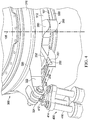
- FIG. 4 a perspective view of contact between a verification device (such as verification tools 100, 200 shown in FIGS. 1 and 2 ) relative to the swashplate assembly 300, and the actuator assemblies 400 is shown.
- a verification device such as verification tools 100, 200 shown in FIGS. 1 and 2
- the verification device 100, 200 may rotate along travel arc 107 around the collective sleeve 510 between the upper and lower flanges 520, 530 of the mast 500.
- the inner surface 112, 212 (of the first section 110, 220) is held in contact with the curved surface 512 of the collective sleeve 510.
- the upper surface 116, 216 is held in contact with the upper flange 520.
- the lower surface 118, 218 is held in contact with the lower flange 530.
- the verification device 100, 200 is configured to move in rotation about central axis 105 and along the travel arc 107. Upon rotation, contact (i.e., intersection) is made between the gradient surface 150, 250 of the verification device 100, 200 and indexable portions of the swashplate lug 322. After contact is made, the device 100, 200 provides an indication of the height measurement based on the graduation indication 151, 251 where contact with the swashplate lug 322 has occurred. Subsequently, an evaluation may be made as to whether the measured height is within an acceptable range (e.g., a second range 154, 254) of the verification device 100, 200. If the detected measured contact is within the second range 154, 254, the main rotor swashplate positioning is deemed proper.
- an acceptable range e.g., a second range 154, 254
- the main rotor swashplate positioning is deemed improper, and appropriate adjustment of the actuator end 412 may be required.
- adjustments may be made by loosening the actuator rod end 412 (e.g., a jam nut) of the actuators assembly 400 by a separate torque tool.
- the actuator rod end 412 may be adjusted in half-turn (i.e., half-revolutions) increments, where each half-turn is 0.635 mm (0.025 inches). Accordingly, the number of half turn adjustments to be made is equal to the number of graduation indications 151, 251 that corresponds to the desired adjustment, in order that the swashplate lug 322 contacts the verification device 100, 200 somewhere within the second range 154, 254.
- the following is an example of a verification and adjustment operation of main rotor rigging of a rotorcraft.
- the verification device along with aircraft mating surfaces, including the collective sleeve 510, the upper and lower flanges 520, 530, and the swashplate lug 322 are cleaned to remove grease, oil, dirt, and other particulates.
- this example assumes that sufficient hydraulics and power is provided to the rotorcraft from maintenance equipment, and that flight control systems (e.g., cyclic stick, collective lever, or fly-by-wire cyclic and collective controls) are configured such that a level swashplate condition is commanded.
- flight control systems e.g., cyclic stick, collective lever, or fly-by-wire cyclic and collective controls
- first, second, and third swashplate lugs (one of which is shown in FIG. 4 by the representative swashplate lug 322) of a swashplate assembly 300 that are coupled to respective first, second, and third actuators assemblies (one of which is shown in FIG. 4 by the representative actuators assembly 400) are positioned according to a predetermined angle relative to the mast 500 (e.g., substantially perpendicular to the mast 500 within approximately 0.5 degrees) and at a predetermined collective height.
- the predetermined collective height may be provided by a rigging specification/manual associated with the particular rotorcraft.
- One skilled in the art will appreciate that alternative geometries of swashplate lugs are possible, and, therefore, the desired angle between the mast 500 and swashplate lug 322 maybe different in different applications.
- the verification tool 100, 200 is initially positioned such that an inner surface 112, 212 (of the first section 110) is held in contact with the curved surface 512 of the collective sleeve 510 between the upper and lower flanges 520, 530 of the mast 500. Also, in the initial positioning, the upper surface 116, 216 is held in contact with the upper flange 520. In addition, or as an alternative, the lower surface 118, 218 is held in contact with the lower flange 530. After the initial positioning, the verification tool 100, 200 is held in contact with the collective sleeve 510, while being rotated about central axis 105, along the travel arc 107 until contact is made with the respective swashplate lug.
- the verification tool 100, 200 is used to measure the respective heights of each of the swashplate lugs. To do so, measurements (i.e., indexing) are taken as to where on the gradient surface 150, 250 of the verification tool 100, 200, contact for each of the swashplate lugs has occurred.
- the main rotor swashplate assembly 300 is substantially normal to the mast 500 and the main rotor rigging of the rotorcraft is deemed acceptable.
- predetermined number of graduations may vary according to different embodiments, depending on the geometry of the tool 100, 200, the slope of the gradient surface 150, 250, the height of the graduation indications 151, 251, and the aircraft requirements.
- any of the three swashplate lugs is detected to be in the first or third ranges 152, 156, 252, 256, i.e., at a height that corresponds to a graduation indication 151, 251 outside the range of acceptable swashplate height, adjustments of actuators assemblies may be required.
- the swashplate lugs are more than a predetermined number of graduations apart (e.g., five graduations) one of the actuators assemblies would be at a greater height than another, thus tilting the swashplate assembly 300 and impacting blade angles. Consequently, control margins may be lost resulting in an improper execution of flight control commands.
- an adjustment may be made by loosening an actuator rod end (e.g., actuator rod end 412) (e.g., a jam nut) of a respective actuators assembly by a separate torque tool.
- the actuator rod end may be adjusted in half-turn (i.e., half-revolutions) increments, where each half-turn is 0.635 mm (0.025 inches).
- the number of half turn adjustments to be made is equal to the number of measurement graduation indications 151, 251 that corresponds to the desired adjustment, in order that the respective swashplate lug's measurement is located within the second range 154, 254 and within the predetermined number of graduations from the measurements of the other two swashplate lugs (e.g., the measured contacts on the verification tool 100, 200 are no more than five graduations apart).
- adjustments may be made to at least one of the actuator assemblies.
- a second determination of measurements and evaluations using the verification tool 100, 200 in accordance with the above paragraphs herein, may again be performed on the first, second, and third swashplate lugs to verify proper main rotor rigging.
- FIG. 5 is a flowchart of a method 600 of verifying at least one main rotor swashplate positioning of a rotorcraft, which was described above in detail with reference to the example verification operation of main rotor swashplate positioning.
- Method 600 may be performed by a verification tool (e.g., a device such verification tools 100, 200 as described with reference to FIGS. 1 and 2 ), the swashplate assembly 300, the actuators assembly 400, and the mast 500 of FIGS. 1-4 .
- a verification tool e.g., a device such verification tools 100, 200 as described with reference to FIGS. 1 and 2
- the swashplate assembly 300, the actuators assembly 400, and the mast 500 of FIGS. 1-4 e.g., a device such verification tools 100, 200 as described with reference to FIGS. 1 and 2 .
- method 600 includes providing for a verification device.
- a verification device such as verification tool 100 or verification tool 200 may be provided.
- an inner surface of the verification device is placed in contact with a convex surface of a collective sleeve of a main rotor mast.
- an inner surface 112, 212 i.e., a concave surface
- the verification device 100 may be positioned on a curved surface 512 (i.e., a convex surface) of a collective sleeve 510 of a main rotor mast 500.
- At 606 at least one of an upper or lower surface of the verification device is placed in contact with a corresponding flange of the collective sleeve.
- a corresponding flange of the collective sleeve For example, as described with reference to FIGS. 1-4 , at least one of an upper surface 116, 216 or lower surface 118, 218 may be placed in contact with a corresponding flange, the upper flange 520 or 530, respectively, of the collective sleeve 510.
- the verification device may be rotated around the collective sleeve of the mast.
- the verification device 100, 200 may be rotated around the collective sleeve 510 of the main rotor mast 500.
- a swashplate lug of the main rotor swashplate is contacted by a gradient surface of the verification device.
- a swashplate lug 332 of the swashplate assembly 300 may be contacted by the gradient surface 150, 250 of the verification device 100, 200.
- the swashplate lug height is measured by a plurality of graduation indications on the gradient surface of the verification device.
- the swashplate lug 332 may be measured by a plurality of graduation indications 151, 251 on the gradient surface 150, 250 of the verification device 100, 200.
- an evaluation is made whether the measured height is within an acceptable range of the verification device. For example, as described with reference to FIGS. 1-4 , an evaluation is made whether the height of the measured contact is detected on the second range 152, 252 of the gradient surface 150, 250 of the verification device 100, 200.
- the second range 152, 252 may include graduation indications that are within the range of acceptable swashplate height.
- one or more actuators assemblies are adjusted based on the evaluation of the measured height.
- an actuators assembly 400 may be adjusted based on the evaluation of the measured height for a particular actuators assembly falling out of the acceptable range alone, or with respect to the measurements of the other actuators assemblies.
- the above steps 602 to 616 may be repeated for additional swashplate lugs to complete the rigging and the verifying of the main rotor in accordance with the example verification and adjustment operation of main rotor rigging of a rotorcraft (as described in detail in above paragraphs and further described below in FIG. 6 ).
- FIG. 6 is a flowchart of a method 700 of verifying main rotor rigging of a rotorcraft, which was described above in detail with reference to the example verification and adjustment operation of main rotor rigging of a rotorcraft.
- Method 700 may be performed by a verification tool (e.g., a device such verification tools 100, 200 as described with reference to FIGS. 1 and 2 ), a torque tool (not shown), the swashplate assembly 300, at least three hydraulic actuators assemblies (e.g., as described by representative actuators assembly 400), and the mast 500.
- a verification tool e.g., a device such verification tools 100, 200 as described with reference to FIGS. 1 and 2
- a torque tool not shown
- the swashplate assembly 300 e.g., as described by representative actuators assembly 400
- the mast 500 e.g., as described by representative actuators assembly 400
- method 700 includes a first determination, using a verification tool, whether first, second, and third swashplate lugs of a swashplate assembly (that are coupled to respective first, second, and third actuators assemblies) are positioned at a predetermined angle relative to a main rotor mast (e.g., substantially normal to a main rotor mast) and at a predetermined collective height.
- the verification tool 100, 200 may be used to determine whether first, second, and third swashplate lugs (as shown by the representative swashplate lug 322 in FIGS.
- a swashplate assembly 300 that are coupled to respective first, second, and third actuators assemblies (as shown by the representative actuators assembly 400 in FIGS. 3-4 )) are positioned substantially normal to a mast 500 and at a predetermined collective height.
- adjustable rod ends coupled to the first, second, and third actuators assemblies may be adjusted.
- adjustable rod ends as shown by the representative adjustable rod ends 412 in FIGS. 3-4
- adjustable rod ends coupled to the first, second, and third actuators assemblies (as shown by the representative actuators assembly 400 in FIGS. 3-4 ) may be adjusted.
- the verification tools 100, 200 may be used to determine whether the swashplate lugs (as shown by the representative swashplate lug 322 in FIGS. 3-4 ) are positioned substantially normal to the mast 500 and at the predetermined collective height.
- a system integrator may include, without limitation, any number of manufacturers and major-system subcontractors; a third party may include, without limitation, any number of vendors, subcontractors, and suppliers; and an operator may be a leasing company, military entity, service organization, and so on.
- first, second, etc. are used herein merely as labels, and are not intended to impose ordinal, positional, or hierarchical requirements on the items to which these terms refer. Moreover, reference to, e.g., a “second” item does not require or preclude the existence of, e.g., a "first” or lower-numbered item, and/or, e.g., a "third" or higher-numbered item.
- Device(s) and method(s) shown or described herein may be employed during any one or more of the stages of the verification of swashplate positioning and/or main rotor rigging of the device 100, the device 200, the method 600, and the method 700.
Landscapes
- Engineering & Computer Science (AREA)
- Aviation & Aerospace Engineering (AREA)
- Manufacturing & Machinery (AREA)
- Transportation (AREA)
- Physics & Mathematics (AREA)
- General Physics & Mathematics (AREA)
- Mechanical Engineering (AREA)
- Testing Of Devices, Machine Parts, Or Other Structures Thereof (AREA)
- A Measuring Device Byusing Mechanical Method (AREA)
Claims (14)
- Vorrichtung (100, 200) zum Verifizieren der Positionierung der Hauptrotortaumelscheibe, umfassend:eine erste Fläche (112, 212) eines ersten Abschnitts (110, 210) undeine Gradientenfläche (150, 250) eines zweiten Abschnitts (120, 220) mit einer Vielzahl von Inkrementalstufen (151, 251),wobei der erste und der zweite Abschnitt (110, 210, 120, 220) parallel und konzentrisch bezüglich einer mittleren Achse sind,wobei die erste Fläche (112, 200) dazu ausgestaltet ist, an einer konvexen Krümmung (512) einer Kollektiv-Steuerhülse (510) eines Hauptrotormasts (500) anzuliegen,wobei die Gradientenfläche (150, 250) zum Kontaktieren einer Taumelscheibennase (322) einer Hauptrotortaumelscheibe ausgestaltet ist undwobei die Gradientenfläche (150, 250), die eine Vielzahl von Inkrementalstufen (151, 251) hat, geneigt ist.
- Vorrichtung (100, 200) nach Anspruch 1, ferner umfassend eine Innenfläche des zweiten Abschnitts (120, 220), die der Gradientenfläche (150, 250) benachbart ist und im Wesentlichen senkrecht dazu verläuft.
- Vorrichtung (100, 200) nach Anspruch 2, ferner umfassend:
eine benachbarte Fläche eines benachbarten Abschnitts, die im Wesentlichen senkrecht zu der ersten Fläche (112, 220) des ersten Abschnitts (110, 210) und der Gradientenfläche (150, 250) des zweiten Abschnitts (120, 220) verläuft, wobei die benachbarte Fläche zwischen dem ersten Abschnitt (110, 210) und dem zweiten Abschnitt (120, 220) benachbart ist. - Vorrichtung (100, 200) nach Anspruch 1 oder nach Anspruch 2 oder nach Anspruch 3, wobei die erste Fläche (112, 220) des ersten Abschnitts (110, 210) mindestens teilweise einen Bewegungsbogen definiert, der parallel zu der ersten Fläche (112, 212) verläuft und konzentrisch zu dieser ist, und wobei die Vorrichtung (100, 200) dazu ausgestaltet ist, sich entlang dem Bewegungsbogen zu bewegen, während sie sich um die Kollektiv-Steuerhülse (510) dreht, um die Taumelscheibennase (322) zu kontaktieren.
- Vorrichtung (100, 200) nach Anspruch 1 oder nach einem der vorhergehenden Ansprüche, wobei die erste Fläche (112, 212) des ersten Abschnitts (110, 210) und die Krümmung der Kollektiv-Steuerhülse im Wesentlichen denselben Radius haben.
- Vorrichtung (100, 200) nach Anspruch 1 oder nach einem der vorhergehenden Ansprüche, ferner umfassend eine untere Fläche des ersten Abschnitts (110, 210), die im Wesentlichen senkrecht zu der ersten Fläche (112, 212) des ersten Abschnitts (110, 210) verläuft.
- Vorrichtung (100, 200) nach Anspruch 1 oder nach einem der vorhergehenden Ansprüche, wobei jede Inkrementalstufe der Vielzahl von Inkrementalstufen einem Höheninkrement von ungefähr 0,635 mm (0,025 Zoll) entspricht, und optional oder vorzugsweise wobei jedes der Höheninkremente der Vielzahl von Inkrementalstufen einen Vektor parallel zu einer Mastachse definiert.
- Vorrichtung (100, 200) nach Anspruch 1 oder nach einem der vorhergehenden Ansprüche, wobei:(i) jede der Vielzahl von Inkrementalstufen die Vielzahl von Inkrementalstufen definiert und eine Intervallbreite hat und/oder(ii) wobei die Gradientenfläche (150, 250) eine Neigung umfasst und wobei jede der Vielzahl von Inkrementalstufen an der Neigung maschinell bearbeitet oder markiert ist.
- Vorrichtung (100, 200) nach Anspruch 1 oder nach einem der vorhergehenden Ansprüche, wobei die Vielzahl von Inkrementalstufen in einen ersten, einen zweiten und einen dritten Bereich gruppiert sind, wobei der erste und der dritte Bereich Höhenbereiche angeben, die außerhalb eines annehmbaren Taumelscheibenhöhenbereichs liegen, und wobei der zweite Bereich Höhenbereiche angibt, die innerhalb des annehmbaren Taumelscheibenhöhenbereichs liegen, und optional oder vorzugsweise wobei der erste und der dritte Bereich jeweils sechs Inkrementalstufen aufweist und wobei der zweite Bereich zehn Inkrementalstufen aufweist.
- Vorrichtung (100, 200) nach Anspruch 1 oder nach einem der vorhergehenden Ansprüche, ferner umfassend einen Griff und optional oder vorzugsweise ferner umfassend eine untere Fläche des ersten Abschnitts (110, 210), die im Wesentlichen senkrecht zu der ersten Fläche (112, 212) des ersten Abschnitts (110, 210) verläuft.
- Verfahren zum Verifizieren der Positionierung der Hauptrotortaumelscheibe eines Rotorflugzeugs, umfassend:Bereitstellen einer Verifizierungsvorrichtung (100, 200),Platzieren einer ersten Fläche (112, 212) der Verifizierungsvorrichtung (100, 200) in Kontakt mit einer konvexen Krümmung einer Kollektiv-Steuerhülse eines Hauptrotormasts,Platzieren einer oberen und/oder einer unteren Fläche (116, 118, 216, 218) der Verifizierungsvorrichtung (100, 200) in Kontakt mit einem entsprechenden Flansch der Kollektiv-Steuerhülse,Drehen der Verifizierungsvorrichtung (100, 200) um die Kollektiv-Steuerhülse,Kontaktieren einer ersten Taumelscheibennase (322) der Hauptrotortaumelscheibe (300) mit einer Gradientenfläche (150, 250) der Verifizierungsvorrichtung (100, 200),Messen einer Höhe der ersten Taumelscheibennase (322) mittels einer Vielzahl von Graduierungsmarkierungen an der Gradientenfläche (150, 250) und Auswerten, ob die gemessene Höhe in einem annehmbaren Bereich ist.
- Verfahren nach Anspruch 11, ferner umfassend:
Verstellen einer oder mehrerer Aktuatoranordnungen auf der Grundlage der Auswertung der gemessenen Höhe. - Verfahren nach Anspruch 11 oder 12, ferner umfassend:Bestimmen unter Verwendung der Verifizierungsvorrichtung (100, 200), ob die erste, zweite und dritte Taumelscheibennase (322) der Hauptrotortaumelscheibe (300), die an eine jeweilige erste, zweite und dritte Aktuatoranordnung gekoppelt sind, in Übereinstimmung mit einem vorbestimmten Winkel zu einem Hauptrotormast und auf einer vorbestimmten Kollektiv-Höhe positioniert sind,Verstellen von verstellbaren Stangenenden, die an die erste, zweite und dritte Aktuatoranordnung gekoppelt sind, undBestimmen unter Verwendung der Verifizierungsvorrichtung (100, 200), ob die Taumelscheibennasen (322) der Hauptrotortaumelscheibe (300) in Übereinstimmung mit dem vorbestimmten Winkel zu dem Hauptrotormast und auf der vorbestimmten Kollektiv-Höhe positioniert sind.
- Verfahren nach Anspruch 13, wobei der erste und der zweite Bestimmungsschritt ferner Folgendes umfassen:Auswerten unter Verwendung der Verifizierungsvorrichtung (100, 200), ob Messungen der ersten, zweiten und dritten Taumelscheibennase (322) in einem annehmbaren Bereich der Verifizierungsvorrichtung (100, 200) liegen, undAuswerten, ob die erste, zweite und dritte Taumelscheibennase (322) innerhalb einer vorbestimmten Anzahl von Graduierungsmarkierungen voneinander an einer Gradientenfläche (150, 250) der Verifizierungsvorrichtung (100, 200) liegen, und optional oder vorzugsweise wobei das Verstellen der verstellbaren Stangenenden mittels einer Drehmomentvorrichtung durchgeführt wird und wobei jede Halbumdrehung der verstellbaren Stangenenden einer Graduierungsmarkierung auf der Gradientenfläche (150, 250) der Verifizierungsvorrichtung (100, 200) entspricht.
Applications Claiming Priority (2)
| Application Number | Priority Date | Filing Date | Title |
|---|---|---|---|
| US201862658205P | 2018-04-16 | 2018-04-16 | |
| US16/182,442 US10967990B2 (en) | 2018-04-16 | 2018-11-06 | Devices and methods to verify main rotor swashplate positioning |
Publications (2)
| Publication Number | Publication Date |
|---|---|
| EP3556653A1 EP3556653A1 (de) | 2019-10-23 |
| EP3556653B1 true EP3556653B1 (de) | 2021-07-14 |
Family
ID=65010694
Family Applications (1)
| Application Number | Title | Priority Date | Filing Date |
|---|---|---|---|
| EP19151059.3A Active EP3556653B1 (de) | 2018-04-16 | 2019-01-09 | Systeme und verfahren zur überprüfung der positionierung der hauptrotortaumelscheibe |
Country Status (2)
| Country | Link |
|---|---|
| US (3) | US10967990B2 (de) |
| EP (1) | EP3556653B1 (de) |
Families Citing this family (1)
| Publication number | Priority date | Publication date | Assignee | Title |
|---|---|---|---|---|
| US10967990B2 (en) * | 2018-04-16 | 2021-04-06 | Bell Helicopter Textron Inc. | Devices and methods to verify main rotor swashplate positioning |
Family Cites Families (22)
| Publication number | Priority date | Publication date | Assignee | Title |
|---|---|---|---|---|
| US1558678A (en) * | 1925-03-16 | 1925-10-27 | Richard F Koenig | Paper-hanger's trimming gauge |
| US2536401A (en) * | 1944-09-14 | 1951-01-02 | Victor Victor | Gauge block |
| US2607124A (en) * | 1949-09-19 | 1952-08-19 | Roland F Dery | Adjustable gauge block |
| US2821022A (en) * | 1955-03-21 | 1958-01-28 | Lester J Woodward | Gage holder and scale means-attachment holder and new rules |
| US2970367A (en) | 1957-09-03 | 1961-02-07 | United Aircraft Corp | Method of mounting balanced rotor blades |
| US3201873A (en) * | 1963-05-29 | 1965-08-24 | James C Bell | Gage block |
| US4584774A (en) * | 1984-11-26 | 1986-04-29 | Link Glennie W | Step gauge for setting up wood working tools for specialty processing |
| US5042161A (en) * | 1985-10-07 | 1991-08-27 | Joseph Hodge | Intravascular sizing method and apparatus |
| US5485497A (en) | 1991-11-12 | 1996-01-16 | Hitachi, Ltd. | Optical element and projection exposure apparatus employing the same |
| JPH10170205A (ja) * | 1996-12-12 | 1998-06-26 | Fuji Photo Film Co Ltd | 間隙寸法検出方法および間隙寸法検出用積層体 |
| US5785497A (en) | 1997-03-11 | 1998-07-28 | Sikorsky Aircraft Corporation | Control rod mounting arrangement for helicopter swashplates |
| US6434852B1 (en) * | 2000-02-09 | 2002-08-20 | Pacific Rack & Machine, Llc | Tool gauge |
| US6644081B1 (en) * | 2002-02-15 | 2003-11-11 | Joseph Keith Berry | System and method for adjusting helicopter blade trim tabs |
| US6901672B1 (en) * | 2003-05-08 | 2005-06-07 | Paul J. Reilly | Caliper gauge |
| US7637026B2 (en) * | 2008-03-10 | 2009-12-29 | Ta-Sen Tu | Main rotor blade calibration gauge for remote-controlled toy helicopter |
| US8745888B2 (en) * | 2011-06-07 | 2014-06-10 | General Electric Company | Alignment tool for use with a wind turbine inspection system and methods of assembling same |
| US8793856B2 (en) | 2012-02-20 | 2014-08-05 | Bell Helicopter Textron Inc. | Pitch link alignment tool |
| US20130240663A1 (en) * | 2012-03-16 | 2013-09-19 | Richard Lohr | Under swash leveling tool for radio controlled helicopters |
| US9151162B2 (en) * | 2012-11-08 | 2015-10-06 | Bell Helicopter Textron Inc. | Preventing rotation of a fixed ring of a swashplate |
| PL2979978T3 (pl) * | 2014-07-31 | 2017-02-28 | Airbus Helicopters Deutschland GmbH | Układ sterowania do sterowania skokiem zbiorowym i skokiem cyklicznym łopat wirnika wielopłatowego w wiropłacie |
| US20180319009A1 (en) * | 2016-01-15 | 2018-11-08 | Jamieson Byrt | Pipe spacing wedge systems |
| US10967990B2 (en) * | 2018-04-16 | 2021-04-06 | Bell Helicopter Textron Inc. | Devices and methods to verify main rotor swashplate positioning |
-
2018
- 2018-11-06 US US16/182,442 patent/US10967990B2/en active Active
-
2019
- 2019-01-09 EP EP19151059.3A patent/EP3556653B1/de active Active
-
2021
- 2021-04-05 US US17/222,967 patent/US11685553B2/en active Active
-
2023
- 2023-06-16 US US18/211,177 patent/US12606320B2/en active Active
Non-Patent Citations (1)
| Title |
|---|
| ANONYMOUS: "Protractor - Wikipedia, the free encyclopedia", 5 November 2007 (2007-11-05), XP055706459, Retrieved from the Internet <URL:https://web.archive.org/web/20071105045418/https://en.wikipedia.org/wiki/Protractor> [retrieved on 20200618] * |
Also Published As
| Publication number | Publication date |
|---|---|
| US20190315494A1 (en) | 2019-10-17 |
| US20230331400A1 (en) | 2023-10-19 |
| US20210221539A1 (en) | 2021-07-22 |
| US10967990B2 (en) | 2021-04-06 |
| EP3556653A1 (de) | 2019-10-23 |
| US12606320B2 (en) | 2026-04-21 |
| US11685553B2 (en) | 2023-06-27 |
Similar Documents
| Publication | Publication Date | Title |
|---|---|---|
| US5824897A (en) | Blade static balancing fixture | |
| US12606320B2 (en) | Devices and methods to verify main rotor swashplate positioning | |
| EP0199961B1 (de) | Messen technischer Bestandteile | |
| JP6668502B2 (ja) | プラットフォーム荷重検知システム | |
| CN104075658B (zh) | 激光定位装置及定位方法 | |
| US12297801B2 (en) | Method for connecting two wind turbine blade portions, method for producing a wind turbine, and method for connecting two molded portions | |
| US11780583B2 (en) | Systems and methods for assembling large cargo and loading it onto a cargo aircraft | |
| US20180169768A1 (en) | Machine tool with an assembly configuration with a cantilevered tool | |
| CN111795899B (zh) | 一种扭转加载设备及叶片扭转测试方法 | |
| US20170138715A1 (en) | Blade geometry characterization tool | |
| US11338937B2 (en) | Installation comprising an articulated arm and a machine tool, and corresponding machining method | |
| CN117283354B (zh) | 一种天线罩多角度位姿快速调整工装及其使用方法 | |
| EP1845873B1 (de) | Messgerät und messverfahren für eine rotorblatthalterung | |
| EP3812699B1 (de) | Abtastvorrichtung und abtastverfahren | |
| CN116295212B (zh) | 一种辅助在位集成加工的轮廓检测装置和方法 | |
| US11040785B2 (en) | Devices and methods to verify tail rotor cross-head positioning | |
| US7971496B2 (en) | Method for determining the elastic deformation of components | |
| CN117570788A (zh) | 一种导弹舵片零位调整方法及调整装置 | |
| CN221527623U (zh) | 一种圆柱形构件虚拟轴线标定装置 | |
| US2970367A (en) | Method of mounting balanced rotor blades | |
| CN215726058U (zh) | 一种标定测量定位装置 | |
| CN120293186A (zh) | 一种风标式侧滑角传感器校准工装及校准方法 | |
| Chao et al. | Development of Static Balance Measurement and Correction Compound Platform for Single Blade of Controllable Pitch Propeller | |
| Smith et al. | Join cell for the G150 aircraft | |
| JPS62185112A (ja) | 丸鋳片連続鋳造用鋳型の内面形状測定装置 |
Legal Events
| Date | Code | Title | Description |
|---|---|---|---|
| STAA | Information on the status of an ep patent application or granted ep patent |
Free format text: STATUS: EXAMINATION IS IN PROGRESS |
|
| PUAI | Public reference made under article 153(3) epc to a published international application that has entered the european phase |
Free format text: ORIGINAL CODE: 0009012 |
|
| 17P | Request for examination filed |
Effective date: 20190109 |
|
| AK | Designated contracting states |
Kind code of ref document: A1 Designated state(s): AL AT BE BG CH CY CZ DE DK EE ES FI FR GB GR HR HU IE IS IT LI LT LU LV MC MK MT NL NO PL PT RO RS SE SI SK SM TR |
|
| AX | Request for extension of the european patent |
Extension state: BA ME |
|
| GRAP | Despatch of communication of intention to grant a patent |
Free format text: ORIGINAL CODE: EPIDOSNIGR1 |
|
| STAA | Information on the status of an ep patent application or granted ep patent |
Free format text: STATUS: GRANT OF PATENT IS INTENDED |
|
| INTG | Intention to grant announced |
Effective date: 20210222 |
|
| GRAS | Grant fee paid |
Free format text: ORIGINAL CODE: EPIDOSNIGR3 |
|
| GRAA | (expected) grant |
Free format text: ORIGINAL CODE: 0009210 |
|
| STAA | Information on the status of an ep patent application or granted ep patent |
Free format text: STATUS: THE PATENT HAS BEEN GRANTED |
|
| AK | Designated contracting states |
Kind code of ref document: B1 Designated state(s): AL AT BE BG CH CY CZ DE DK EE ES FI FR GB GR HR HU IE IS IT LI LT LU LV MC MK MT NL NO PL PT RO RS SE SI SK SM TR |
|
| REG | Reference to a national code |
Ref country code: GB Ref legal event code: FG4D |
|
| REG | Reference to a national code |
Ref country code: IE Ref legal event code: FG4D |
|
| REG | Reference to a national code |
Ref country code: DE Ref legal event code: R096 Ref document number: 602019005990 Country of ref document: DE |
|
| REG | Reference to a national code |
Ref country code: AT Ref legal event code: REF Ref document number: 1410462 Country of ref document: AT Kind code of ref document: T Effective date: 20210815 |
|
| REG | Reference to a national code |
Ref country code: LT Ref legal event code: MG9D |
|
| REG | Reference to a national code |
Ref country code: NL Ref legal event code: MP Effective date: 20210714 |
|
| REG | Reference to a national code |
Ref country code: AT Ref legal event code: MK05 Ref document number: 1410462 Country of ref document: AT Kind code of ref document: T Effective date: 20210714 |
|
| PG25 | Lapsed in a contracting state [announced via postgrant information from national office to epo] |
Ref country code: FI Free format text: LAPSE BECAUSE OF FAILURE TO SUBMIT A TRANSLATION OF THE DESCRIPTION OR TO PAY THE FEE WITHIN THE PRESCRIBED TIME-LIMIT Effective date: 20210714 Ref country code: ES Free format text: LAPSE BECAUSE OF FAILURE TO SUBMIT A TRANSLATION OF THE DESCRIPTION OR TO PAY THE FEE WITHIN THE PRESCRIBED TIME-LIMIT Effective date: 20210714 Ref country code: RS Free format text: LAPSE BECAUSE OF FAILURE TO SUBMIT A TRANSLATION OF THE DESCRIPTION OR TO PAY THE FEE WITHIN THE PRESCRIBED TIME-LIMIT Effective date: 20210714 Ref country code: SE Free format text: LAPSE BECAUSE OF FAILURE TO SUBMIT A TRANSLATION OF THE DESCRIPTION OR TO PAY THE FEE WITHIN THE PRESCRIBED TIME-LIMIT Effective date: 20210714 Ref country code: NO Free format text: LAPSE BECAUSE OF FAILURE TO SUBMIT A TRANSLATION OF THE DESCRIPTION OR TO PAY THE FEE WITHIN THE PRESCRIBED TIME-LIMIT Effective date: 20211014 Ref country code: NL Free format text: LAPSE BECAUSE OF FAILURE TO SUBMIT A TRANSLATION OF THE DESCRIPTION OR TO PAY THE FEE WITHIN THE PRESCRIBED TIME-LIMIT Effective date: 20210714 Ref country code: PT Free format text: LAPSE BECAUSE OF FAILURE TO SUBMIT A TRANSLATION OF THE DESCRIPTION OR TO PAY THE FEE WITHIN THE PRESCRIBED TIME-LIMIT Effective date: 20211115 Ref country code: HR Free format text: LAPSE BECAUSE OF FAILURE TO SUBMIT A TRANSLATION OF THE DESCRIPTION OR TO PAY THE FEE WITHIN THE PRESCRIBED TIME-LIMIT Effective date: 20210714 Ref country code: BG Free format text: LAPSE BECAUSE OF FAILURE TO SUBMIT A TRANSLATION OF THE DESCRIPTION OR TO PAY THE FEE WITHIN THE PRESCRIBED TIME-LIMIT Effective date: 20211014 Ref country code: AT Free format text: LAPSE BECAUSE OF FAILURE TO SUBMIT A TRANSLATION OF THE DESCRIPTION OR TO PAY THE FEE WITHIN THE PRESCRIBED TIME-LIMIT Effective date: 20210714 Ref country code: LT Free format text: LAPSE BECAUSE OF FAILURE TO SUBMIT A TRANSLATION OF THE DESCRIPTION OR TO PAY THE FEE WITHIN THE PRESCRIBED TIME-LIMIT Effective date: 20210714 |
|
| PG25 | Lapsed in a contracting state [announced via postgrant information from national office to epo] |
Ref country code: PL Free format text: LAPSE BECAUSE OF FAILURE TO SUBMIT A TRANSLATION OF THE DESCRIPTION OR TO PAY THE FEE WITHIN THE PRESCRIBED TIME-LIMIT Effective date: 20210714 Ref country code: LV Free format text: LAPSE BECAUSE OF FAILURE TO SUBMIT A TRANSLATION OF THE DESCRIPTION OR TO PAY THE FEE WITHIN THE PRESCRIBED TIME-LIMIT Effective date: 20210714 Ref country code: GR Free format text: LAPSE BECAUSE OF FAILURE TO SUBMIT A TRANSLATION OF THE DESCRIPTION OR TO PAY THE FEE WITHIN THE PRESCRIBED TIME-LIMIT Effective date: 20211015 |
|
| REG | Reference to a national code |
Ref country code: DE Ref legal event code: R097 Ref document number: 602019005990 Country of ref document: DE |
|
| PG25 | Lapsed in a contracting state [announced via postgrant information from national office to epo] |
Ref country code: DK Free format text: LAPSE BECAUSE OF FAILURE TO SUBMIT A TRANSLATION OF THE DESCRIPTION OR TO PAY THE FEE WITHIN THE PRESCRIBED TIME-LIMIT Effective date: 20210714 |
|
| PLBE | No opposition filed within time limit |
Free format text: ORIGINAL CODE: 0009261 |
|
| STAA | Information on the status of an ep patent application or granted ep patent |
Free format text: STATUS: NO OPPOSITION FILED WITHIN TIME LIMIT |
|
| PG25 | Lapsed in a contracting state [announced via postgrant information from national office to epo] |
Ref country code: SM Free format text: LAPSE BECAUSE OF FAILURE TO SUBMIT A TRANSLATION OF THE DESCRIPTION OR TO PAY THE FEE WITHIN THE PRESCRIBED TIME-LIMIT Effective date: 20210714 Ref country code: SK Free format text: LAPSE BECAUSE OF FAILURE TO SUBMIT A TRANSLATION OF THE DESCRIPTION OR TO PAY THE FEE WITHIN THE PRESCRIBED TIME-LIMIT Effective date: 20210714 Ref country code: RO Free format text: LAPSE BECAUSE OF FAILURE TO SUBMIT A TRANSLATION OF THE DESCRIPTION OR TO PAY THE FEE WITHIN THE PRESCRIBED TIME-LIMIT Effective date: 20210714 Ref country code: EE Free format text: LAPSE BECAUSE OF FAILURE TO SUBMIT A TRANSLATION OF THE DESCRIPTION OR TO PAY THE FEE WITHIN THE PRESCRIBED TIME-LIMIT Effective date: 20210714 Ref country code: CZ Free format text: LAPSE BECAUSE OF FAILURE TO SUBMIT A TRANSLATION OF THE DESCRIPTION OR TO PAY THE FEE WITHIN THE PRESCRIBED TIME-LIMIT Effective date: 20210714 Ref country code: AL Free format text: LAPSE BECAUSE OF FAILURE TO SUBMIT A TRANSLATION OF THE DESCRIPTION OR TO PAY THE FEE WITHIN THE PRESCRIBED TIME-LIMIT Effective date: 20210714 |
|
| 26N | No opposition filed |
Effective date: 20220419 |
|
| PG25 | Lapsed in a contracting state [announced via postgrant information from national office to epo] |
Ref country code: MC Free format text: LAPSE BECAUSE OF FAILURE TO SUBMIT A TRANSLATION OF THE DESCRIPTION OR TO PAY THE FEE WITHIN THE PRESCRIBED TIME-LIMIT Effective date: 20210714 |
|
| REG | Reference to a national code |
Ref country code: CH Ref legal event code: PL |
|
| REG | Reference to a national code |
Ref country code: BE Ref legal event code: MM Effective date: 20220131 |
|
| PG25 | Lapsed in a contracting state [announced via postgrant information from national office to epo] |
Ref country code: LU Free format text: LAPSE BECAUSE OF NON-PAYMENT OF DUE FEES Effective date: 20220109 |
|
| PG25 | Lapsed in a contracting state [announced via postgrant information from national office to epo] |
Ref country code: BE Free format text: LAPSE BECAUSE OF NON-PAYMENT OF DUE FEES Effective date: 20220131 |
|
| PG25 | Lapsed in a contracting state [announced via postgrant information from national office to epo] |
Ref country code: LI Free format text: LAPSE BECAUSE OF NON-PAYMENT OF DUE FEES Effective date: 20220131 Ref country code: CH Free format text: LAPSE BECAUSE OF NON-PAYMENT OF DUE FEES Effective date: 20220131 |
|
| PG25 | Lapsed in a contracting state [announced via postgrant information from national office to epo] |
Ref country code: IE Free format text: LAPSE BECAUSE OF NON-PAYMENT OF DUE FEES Effective date: 20220109 |
|
| P01 | Opt-out of the competence of the unified patent court (upc) registered |
Effective date: 20230602 |
|
| PG25 | Lapsed in a contracting state [announced via postgrant information from national office to epo] |
Ref country code: MK Free format text: LAPSE BECAUSE OF FAILURE TO SUBMIT A TRANSLATION OF THE DESCRIPTION OR TO PAY THE FEE WITHIN THE PRESCRIBED TIME-LIMIT Effective date: 20210714 Ref country code: CY Free format text: LAPSE BECAUSE OF FAILURE TO SUBMIT A TRANSLATION OF THE DESCRIPTION OR TO PAY THE FEE WITHIN THE PRESCRIBED TIME-LIMIT Effective date: 20210714 |
|
| PG25 | Lapsed in a contracting state [announced via postgrant information from national office to epo] |
Ref country code: HU Free format text: LAPSE BECAUSE OF FAILURE TO SUBMIT A TRANSLATION OF THE DESCRIPTION OR TO PAY THE FEE WITHIN THE PRESCRIBED TIME-LIMIT; INVALID AB INITIO Effective date: 20190109 |
|
| PG25 | Lapsed in a contracting state [announced via postgrant information from national office to epo] |
Ref country code: MT Free format text: LAPSE BECAUSE OF FAILURE TO SUBMIT A TRANSLATION OF THE DESCRIPTION OR TO PAY THE FEE WITHIN THE PRESCRIBED TIME-LIMIT Effective date: 20210714 |
|
| PG25 | Lapsed in a contracting state [announced via postgrant information from national office to epo] |
Ref country code: TR Free format text: LAPSE BECAUSE OF FAILURE TO SUBMIT A TRANSLATION OF THE DESCRIPTION OR TO PAY THE FEE WITHIN THE PRESCRIBED TIME-LIMIT Effective date: 20210714 |
|
| PGFP | Annual fee paid to national office [announced via postgrant information from national office to epo] |
Ref country code: GB Payment date: 20260127 Year of fee payment: 8 |
|
| PGFP | Annual fee paid to national office [announced via postgrant information from national office to epo] |
Ref country code: DE Payment date: 20260128 Year of fee payment: 8 |
|
| PGFP | Annual fee paid to national office [announced via postgrant information from national office to epo] |
Ref country code: IT Payment date: 20260121 Year of fee payment: 8 |
|
| PGFP | Annual fee paid to national office [announced via postgrant information from national office to epo] |
Ref country code: FR Payment date: 20260126 Year of fee payment: 8 |