EP3556577B1 - Ice adaptive tire system - Google Patents
Ice adaptive tire system Download PDFInfo
- Publication number
- EP3556577B1 EP3556577B1 EP19168149.3A EP19168149A EP3556577B1 EP 3556577 B1 EP3556577 B1 EP 3556577B1 EP 19168149 A EP19168149 A EP 19168149A EP 3556577 B1 EP3556577 B1 EP 3556577B1
- Authority
- EP
- European Patent Office
- Prior art keywords
- bolt
- tire
- rotary union
- rotor
- stator body
- Prior art date
- Legal status (The legal status is an assumption and is not a legal conclusion. Google has not performed a legal analysis and makes no representation as to the accuracy of the status listed.)
- Active
Links
- 230000003044 adaptive effect Effects 0.000 title description 38
- 238000000034 method Methods 0.000 claims description 12
- 238000007789 sealing Methods 0.000 claims description 9
- 239000012530 fluid Substances 0.000 claims description 8
- 241000283216 Phocidae Species 0.000 description 73
- 230000000712 assembly Effects 0.000 description 60
- 238000000429 assembly Methods 0.000 description 60
- 230000007246 mechanism Effects 0.000 description 30
- 229910000831 Steel Inorganic materials 0.000 description 16
- 239000010959 steel Substances 0.000 description 16
- 238000010586 diagram Methods 0.000 description 15
- 238000009826 distribution Methods 0.000 description 11
- 239000000463 material Substances 0.000 description 9
- 230000001133 acceleration Effects 0.000 description 8
- 238000004891 communication Methods 0.000 description 7
- 230000006870 function Effects 0.000 description 7
- 210000004907 gland Anatomy 0.000 description 7
- 229910052751 metal Inorganic materials 0.000 description 6
- 239000002184 metal Substances 0.000 description 6
- 238000012423 maintenance Methods 0.000 description 5
- 239000004636 vulcanized rubber Substances 0.000 description 5
- 230000008901 benefit Effects 0.000 description 4
- 230000008859 change Effects 0.000 description 3
- 238000013461 design Methods 0.000 description 3
- 230000002708 enhancing effect Effects 0.000 description 3
- 238000009434 installation Methods 0.000 description 3
- 239000000314 lubricant Substances 0.000 description 3
- 230000004048 modification Effects 0.000 description 3
- 238000012986 modification Methods 0.000 description 3
- 238000004080 punching Methods 0.000 description 3
- 238000009987 spinning Methods 0.000 description 3
- 229920000271 Kevlar® Polymers 0.000 description 2
- 230000009286 beneficial effect Effects 0.000 description 2
- 238000003490 calendering Methods 0.000 description 2
- 238000010276 construction Methods 0.000 description 2
- 230000007423 decrease Effects 0.000 description 2
- 230000000994 depressogenic effect Effects 0.000 description 2
- 238000001514 detection method Methods 0.000 description 2
- 235000012489 doughnuts Nutrition 0.000 description 2
- 230000001965 increasing effect Effects 0.000 description 2
- 230000000977 initiatory effect Effects 0.000 description 2
- 239000004761 kevlar Substances 0.000 description 2
- 238000005461 lubrication Methods 0.000 description 2
- 239000004033 plastic Substances 0.000 description 2
- 229920003023 plastic Polymers 0.000 description 2
- 238000003825 pressing Methods 0.000 description 2
- 230000003014 reinforcing effect Effects 0.000 description 2
- 239000004698 Polyethylene Substances 0.000 description 1
- 244000273618 Sphenoclea zeylanica Species 0.000 description 1
- RTAQQCXQSZGOHL-UHFFFAOYSA-N Titanium Chemical compound [Ti] RTAQQCXQSZGOHL-UHFFFAOYSA-N 0.000 description 1
- 230000004308 accommodation Effects 0.000 description 1
- 230000009471 action Effects 0.000 description 1
- 230000003213 activating effect Effects 0.000 description 1
- 229910052782 aluminium Inorganic materials 0.000 description 1
- XAGFODPZIPBFFR-UHFFFAOYSA-N aluminium Chemical compound [Al] XAGFODPZIPBFFR-UHFFFAOYSA-N 0.000 description 1
- 239000010426 asphalt Substances 0.000 description 1
- 230000000295 complement effect Effects 0.000 description 1
- 230000006835 compression Effects 0.000 description 1
- 238000007906 compression Methods 0.000 description 1
- 230000008878 coupling Effects 0.000 description 1
- 238000010168 coupling process Methods 0.000 description 1
- 238000005859 coupling reaction Methods 0.000 description 1
- 238000005520 cutting process Methods 0.000 description 1
- 230000001934 delay Effects 0.000 description 1
- 230000000779 depleting effect Effects 0.000 description 1
- 239000000835 fiber Substances 0.000 description 1
- 239000011152 fibreglass Substances 0.000 description 1
- 230000008676 import Effects 0.000 description 1
- 230000001050 lubricating effect Effects 0.000 description 1
- 150000002739 metals Chemical class 0.000 description 1
- 238000005457 optimization Methods 0.000 description 1
- 230000000737 periodic effect Effects 0.000 description 1
- 230000002093 peripheral effect Effects 0.000 description 1
- 230000002085 persistent effect Effects 0.000 description 1
- 238000009428 plumbing Methods 0.000 description 1
- -1 polyethylene Polymers 0.000 description 1
- 229920000573 polyethylene Polymers 0.000 description 1
- 239000004810 polytetrafluoroethylene Substances 0.000 description 1
- 229920001343 polytetrafluoroethylene Polymers 0.000 description 1
- 230000002787 reinforcement Effects 0.000 description 1
- 230000008439 repair process Effects 0.000 description 1
- 230000004044 response Effects 0.000 description 1
- 238000005096 rolling process Methods 0.000 description 1
- 239000004576 sand Substances 0.000 description 1
- 239000000126 substance Substances 0.000 description 1
- 239000000725 suspension Substances 0.000 description 1
- 239000010936 titanium Substances 0.000 description 1
- 229910052719 titanium Inorganic materials 0.000 description 1
- 238000011144 upstream manufacturing Methods 0.000 description 1
- 238000013022 venting Methods 0.000 description 1
Images


Classifications
-
- B—PERFORMING OPERATIONS; TRANSPORTING
- B60—VEHICLES IN GENERAL
- B60C—VEHICLE TYRES; TYRE INFLATION; TYRE CHANGING; CONNECTING VALVES TO INFLATABLE ELASTIC BODIES IN GENERAL; DEVICES OR ARRANGEMENTS RELATED TO TYRES
- B60C11/00—Tyre tread bands; Tread patterns; Anti-skid inserts
- B60C11/14—Anti-skid inserts, e.g. vulcanised into the tread band
- B60C11/16—Anti-skid inserts, e.g. vulcanised into the tread band of plug form, e.g. made from metal, textile
- B60C11/1606—Anti-skid inserts, e.g. vulcanised into the tread band of plug form, e.g. made from metal, textile retractable plug
- B60C11/1612—Anti-skid inserts, e.g. vulcanised into the tread band of plug form, e.g. made from metal, textile retractable plug actuated by fluid, e.g. using fluid pressure difference
-
- B—PERFORMING OPERATIONS; TRANSPORTING
- B60—VEHICLES IN GENERAL
- B60C—VEHICLE TYRES; TYRE INFLATION; TYRE CHANGING; CONNECTING VALVES TO INFLATABLE ELASTIC BODIES IN GENERAL; DEVICES OR ARRANGEMENTS RELATED TO TYRES
- B60C11/00—Tyre tread bands; Tread patterns; Anti-skid inserts
- B60C11/14—Anti-skid inserts, e.g. vulcanised into the tread band
- B60C11/16—Anti-skid inserts, e.g. vulcanised into the tread band of plug form, e.g. made from metal, textile
- B60C11/1625—Arrangements thereof in the tread patterns, e.g. irregular
-
- B—PERFORMING OPERATIONS; TRANSPORTING
- B60—VEHICLES IN GENERAL
- B60C—VEHICLE TYRES; TYRE INFLATION; TYRE CHANGING; CONNECTING VALVES TO INFLATABLE ELASTIC BODIES IN GENERAL; DEVICES OR ARRANGEMENTS RELATED TO TYRES
- B60C11/00—Tyre tread bands; Tread patterns; Anti-skid inserts
- B60C11/14—Anti-skid inserts, e.g. vulcanised into the tread band
- B60C11/16—Anti-skid inserts, e.g. vulcanised into the tread band of plug form, e.g. made from metal, textile
- B60C11/1637—Attachment of the plugs into the tread, e.g. screwed
-
- B—PERFORMING OPERATIONS; TRANSPORTING
- B60—VEHICLES IN GENERAL
- B60C—VEHICLE TYRES; TYRE INFLATION; TYRE CHANGING; CONNECTING VALVES TO INFLATABLE ELASTIC BODIES IN GENERAL; DEVICES OR ARRANGEMENTS RELATED TO TYRES
- B60C11/00—Tyre tread bands; Tread patterns; Anti-skid inserts
- B60C11/14—Anti-skid inserts, e.g. vulcanised into the tread band
- B60C11/16—Anti-skid inserts, e.g. vulcanised into the tread band of plug form, e.g. made from metal, textile
- B60C11/1693—Attachment of the plug-tip within the plug-body
-
- B—PERFORMING OPERATIONS; TRANSPORTING
- B60—VEHICLES IN GENERAL
- B60C—VEHICLE TYRES; TYRE INFLATION; TYRE CHANGING; CONNECTING VALVES TO INFLATABLE ELASTIC BODIES IN GENERAL; DEVICES OR ARRANGEMENTS RELATED TO TYRES
- B60C23/00—Devices for measuring, signalling, controlling, or distributing tyre pressure or temperature, specially adapted for mounting on vehicles; Arrangement of tyre inflating devices on vehicles, e.g. of pumps or of tanks; Tyre cooling arrangements
- B60C23/001—Devices for manually or automatically controlling or distributing tyre pressure whilst the vehicle is moving
- B60C23/003—Devices for manually or automatically controlling or distributing tyre pressure whilst the vehicle is moving comprising rotational joints between vehicle-mounted pressure sources and the tyres
- B60C23/00309—Devices for manually or automatically controlling or distributing tyre pressure whilst the vehicle is moving comprising rotational joints between vehicle-mounted pressure sources and the tyres characterised by the location of the components, e.g. valves, sealings, conduits or sensors
- B60C23/00318—Devices for manually or automatically controlling or distributing tyre pressure whilst the vehicle is moving comprising rotational joints between vehicle-mounted pressure sources and the tyres characterised by the location of the components, e.g. valves, sealings, conduits or sensors on the wheels or the hubs
-
- B—PERFORMING OPERATIONS; TRANSPORTING
- B60—VEHICLES IN GENERAL
- B60C—VEHICLE TYRES; TYRE INFLATION; TYRE CHANGING; CONNECTING VALVES TO INFLATABLE ELASTIC BODIES IN GENERAL; DEVICES OR ARRANGEMENTS RELATED TO TYRES
- B60C23/00—Devices for measuring, signalling, controlling, or distributing tyre pressure or temperature, specially adapted for mounting on vehicles; Arrangement of tyre inflating devices on vehicles, e.g. of pumps or of tanks; Tyre cooling arrangements
- B60C23/001—Devices for manually or automatically controlling or distributing tyre pressure whilst the vehicle is moving
- B60C23/003—Devices for manually or automatically controlling or distributing tyre pressure whilst the vehicle is moving comprising rotational joints between vehicle-mounted pressure sources and the tyres
- B60C23/00345—Details of the rotational joints
- B60C23/00347—Details of the rotational joints comprising two or more feedthrough
-
- B—PERFORMING OPERATIONS; TRANSPORTING
- B60—VEHICLES IN GENERAL
- B60C—VEHICLE TYRES; TYRE INFLATION; TYRE CHANGING; CONNECTING VALVES TO INFLATABLE ELASTIC BODIES IN GENERAL; DEVICES OR ARRANGEMENTS RELATED TO TYRES
- B60C23/00—Devices for measuring, signalling, controlling, or distributing tyre pressure or temperature, specially adapted for mounting on vehicles; Arrangement of tyre inflating devices on vehicles, e.g. of pumps or of tanks; Tyre cooling arrangements
- B60C23/001—Devices for manually or automatically controlling or distributing tyre pressure whilst the vehicle is moving
- B60C23/003—Devices for manually or automatically controlling or distributing tyre pressure whilst the vehicle is moving comprising rotational joints between vehicle-mounted pressure sources and the tyres
- B60C23/00354—Details of valves
-
- B—PERFORMING OPERATIONS; TRANSPORTING
- B60—VEHICLES IN GENERAL
- B60C—VEHICLE TYRES; TYRE INFLATION; TYRE CHANGING; CONNECTING VALVES TO INFLATABLE ELASTIC BODIES IN GENERAL; DEVICES OR ARRANGEMENTS RELATED TO TYRES
- B60C23/00—Devices for measuring, signalling, controlling, or distributing tyre pressure or temperature, specially adapted for mounting on vehicles; Arrangement of tyre inflating devices on vehicles, e.g. of pumps or of tanks; Tyre cooling arrangements
- B60C23/001—Devices for manually or automatically controlling or distributing tyre pressure whilst the vehicle is moving
- B60C23/003—Devices for manually or automatically controlling or distributing tyre pressure whilst the vehicle is moving comprising rotational joints between vehicle-mounted pressure sources and the tyres
- B60C23/00363—Details of sealings
-
- B—PERFORMING OPERATIONS; TRANSPORTING
- B60—VEHICLES IN GENERAL
- B60C—VEHICLE TYRES; TYRE INFLATION; TYRE CHANGING; CONNECTING VALVES TO INFLATABLE ELASTIC BODIES IN GENERAL; DEVICES OR ARRANGEMENTS RELATED TO TYRES
- B60C23/00—Devices for measuring, signalling, controlling, or distributing tyre pressure or temperature, specially adapted for mounting on vehicles; Arrangement of tyre inflating devices on vehicles, e.g. of pumps or of tanks; Tyre cooling arrangements
- B60C23/001—Devices for manually or automatically controlling or distributing tyre pressure whilst the vehicle is moving
- B60C23/003—Devices for manually or automatically controlling or distributing tyre pressure whilst the vehicle is moving comprising rotational joints between vehicle-mounted pressure sources and the tyres
- B60C23/00372—Devices for manually or automatically controlling or distributing tyre pressure whilst the vehicle is moving comprising rotational joints between vehicle-mounted pressure sources and the tyres characterised by fluid diagrams
-
- B—PERFORMING OPERATIONS; TRANSPORTING
- B60—VEHICLES IN GENERAL
- B60C—VEHICLE TYRES; TYRE INFLATION; TYRE CHANGING; CONNECTING VALVES TO INFLATABLE ELASTIC BODIES IN GENERAL; DEVICES OR ARRANGEMENTS RELATED TO TYRES
- B60C27/00—Non-skid devices temporarily attachable to resilient tyres or resiliently-tyred wheels
- B60C27/02—Non-skid devices temporarily attachable to resilient tyres or resiliently-tyred wheels extending over restricted arcuate part of tread
- B60C27/04—Non-skid devices temporarily attachable to resilient tyres or resiliently-tyred wheels extending over restricted arcuate part of tread the ground-engaging part being rigid
- B60C27/045—Non-skid devices temporarily attachable to resilient tyres or resiliently-tyred wheels extending over restricted arcuate part of tread the ground-engaging part being rigid involving retractable devices
-
- B—PERFORMING OPERATIONS; TRANSPORTING
- B60—VEHICLES IN GENERAL
- B60C—VEHICLE TYRES; TYRE INFLATION; TYRE CHANGING; CONNECTING VALVES TO INFLATABLE ELASTIC BODIES IN GENERAL; DEVICES OR ARRANGEMENTS RELATED TO TYRES
- B60C27/00—Non-skid devices temporarily attachable to resilient tyres or resiliently-tyred wheels
- B60C27/06—Non-skid devices temporarily attachable to resilient tyres or resiliently-tyred wheels extending over the complete circumference of the tread, e.g. made of chains or cables
- B60C27/068—Non-skid devices temporarily attachable to resilient tyres or resiliently-tyred wheels extending over the complete circumference of the tread, e.g. made of chains or cables the ground-engaging part being rigid
-
- B—PERFORMING OPERATIONS; TRANSPORTING
- B60—VEHICLES IN GENERAL
- B60S—SERVICING, CLEANING, REPAIRING, SUPPORTING, LIFTING, OR MANOEUVRING OF VEHICLES, NOT OTHERWISE PROVIDED FOR
- B60S5/00—Servicing, maintaining, repairing, or refitting of vehicles
-
- F—MECHANICAL ENGINEERING; LIGHTING; HEATING; WEAPONS; BLASTING
- F16—ENGINEERING ELEMENTS AND UNITS; GENERAL MEASURES FOR PRODUCING AND MAINTAINING EFFECTIVE FUNCTIONING OF MACHINES OR INSTALLATIONS; THERMAL INSULATION IN GENERAL
- F16J—PISTONS; CYLINDERS; SEALINGS
- F16J15/00—Sealings
- F16J15/46—Sealings with packing ring expanded or pressed into place by fluid pressure, e.g. inflatable packings
-
- F—MECHANICAL ENGINEERING; LIGHTING; HEATING; WEAPONS; BLASTING
- F16—ENGINEERING ELEMENTS AND UNITS; GENERAL MEASURES FOR PRODUCING AND MAINTAINING EFFECTIVE FUNCTIONING OF MACHINES OR INSTALLATIONS; THERMAL INSULATION IN GENERAL
- F16L—PIPES; JOINTS OR FITTINGS FOR PIPES; SUPPORTS FOR PIPES, CABLES OR PROTECTIVE TUBING; MEANS FOR THERMAL INSULATION IN GENERAL
- F16L27/00—Adjustable joints, Joints allowing movement
- F16L27/08—Adjustable joints, Joints allowing movement allowing adjustment or movement only about the axis of one pipe
- F16L27/0804—Adjustable joints, Joints allowing movement allowing adjustment or movement only about the axis of one pipe the fluid passing axially from one joint element to another
-
- B—PERFORMING OPERATIONS; TRANSPORTING
- B60—VEHICLES IN GENERAL
- B60C—VEHICLE TYRES; TYRE INFLATION; TYRE CHANGING; CONNECTING VALVES TO INFLATABLE ELASTIC BODIES IN GENERAL; DEVICES OR ARRANGEMENTS RELATED TO TYRES
- B60C9/00—Reinforcements or ply arrangement of pneumatic tyres
- B60C9/18—Structure or arrangement of belts or breakers, crown-reinforcing or cushioning layers
- B60C9/20—Structure or arrangement of belts or breakers, crown-reinforcing or cushioning layers built-up from rubberised plies each having all cords arranged substantially parallel
- B60C9/2003—Structure or arrangement of belts or breakers, crown-reinforcing or cushioning layers built-up from rubberised plies each having all cords arranged substantially parallel characterised by the materials of the belt cords
- B60C9/2006—Structure or arrangement of belts or breakers, crown-reinforcing or cushioning layers built-up from rubberised plies each having all cords arranged substantially parallel characterised by the materials of the belt cords consisting of steel cord plies only
-
- Y—GENERAL TAGGING OF NEW TECHNOLOGICAL DEVELOPMENTS; GENERAL TAGGING OF CROSS-SECTIONAL TECHNOLOGIES SPANNING OVER SEVERAL SECTIONS OF THE IPC; TECHNICAL SUBJECTS COVERED BY FORMER USPC CROSS-REFERENCE ART COLLECTIONS [XRACs] AND DIGESTS
- Y10—TECHNICAL SUBJECTS COVERED BY FORMER USPC
- Y10T—TECHNICAL SUBJECTS COVERED BY FORMER US CLASSIFICATION
- Y10T137/00—Fluid handling
- Y10T137/0318—Processes
- Y10T137/0402—Cleaning, repairing, or assembling
-
- Y—GENERAL TAGGING OF NEW TECHNOLOGICAL DEVELOPMENTS; GENERAL TAGGING OF CROSS-SECTIONAL TECHNOLOGIES SPANNING OVER SEVERAL SECTIONS OF THE IPC; TECHNICAL SUBJECTS COVERED BY FORMER USPC CROSS-REFERENCE ART COLLECTIONS [XRACs] AND DIGESTS
- Y10—TECHNICAL SUBJECTS COVERED BY FORMER USPC
- Y10T—TECHNICAL SUBJECTS COVERED BY FORMER US CLASSIFICATION
- Y10T29/00—Metal working
- Y10T29/49—Method of mechanical manufacture
- Y10T29/49718—Repairing
Definitions
- the inventions disclosed herein relate to adaptive tire systems such as, for example, tire systems designed to adapt to changing road conditions such as road conditions changing from dry road to ice covered roads.
- Vehicle tires support wheel axle loads on a tread area in contact with a road surface.
- the sum of contact area of all tires of a vehicle multiplied by inflation pressure of each tire will be equal to the vehicle axle load.
- Coefficients of friction between tread and road surface multiplied by the axle load is the maximum force, parallel to the road surface, that can be applied to the tire contact area by the wheels to stop, accelerate, corner or maintain speed on a grade without tire slippage at the contact between the road and tire.
- a tire tread coefficient of friction is 0.30, and an axle load is 453,6 Kg (1000 pounds)
- the maximum friction force between the tire and road surface before tire slippage will be 136,08 Kg (300 pounds).
- a braking load or an acceleration load, greater than 300 pounds at the tread/road interface is developed, wheel rotation will decrease or increase respectively and when the slippage occurs to some degree, a loss of control may occur.
- Loss of control on ice is typically evidenced by spinning wheels when initiating motion, locking of wheels when braking, and lack of steering response (e.g. "understeering") due to insufficient friction between the tires and road surface for vehicle traction.
- Tire chains and tire studs function by impressing a fixed-shape chain or stud component into ice by tire tread to develop tractive force which is limited by shear values of ice and geometry of components.
- Some known designs for tires with retractable studs rely on perpetual maintenance of air pressure in order to maintain the associated stud in a deployed position. Additionally, some systems use, and thus can deplete, air within a tire in order to cause movement of a stud, for example, between a retracted and a deployed position.
- An aspect of at least one of the inventions disclosed herein includes the realization that using a locking mechanism which provides a locking engagement of a retractable ice engagement member can avoid problems associated with prior known systems noted above.
- a deployable tire stud is maintained in a deployed position only with a perpetual maintenance of internal pressure.
- the studs are pressed against their actuators and the maintained air pressure as well as the associated seals which can cause leakage.
- use of such a tire with studs in a deployed position can deplete the system of air thereby failing to maintain the associated studs in a desired deployed position and or requiring periodic replenishment of lost air.
- an adaptive tire can include a retractable bolt for enhancing traction and a lock mechanism for locking the bolt at least in a deployed position without the need for relying on persistently maintained air pressure to keep the bolt in the deployed position.
- a tire can avoid the problems associated with the need for persistently maintained air pressure and the associated leakage that can occur.
- a system can avoid the depletion of air pressure within a tire that can result from systems which utilize air pressure within the tire for actuation purposes.
- an adaptive tire which includes an air actuation system, can avoid the problems of potentially depleting air pressure within a tire with an air actuation system that is independent of the volume of air within a tire.
- an adaptive tire can include an air actuation system which utilizes compressed air for moving a bolt from a retracted to a deployed position and such an air system can be configured such that the air actuation system is independent of the air utilized for maintaining the tire in an inflated state for supporting axle load.
- the air actuation system can have air inputs and optionally outputs that are independent from ports used for inflating the tire.
- retractable tire bolts can provide better performance where they are adjustable such that their deployed position can be changed. For example, as the tread of a tire wears down and as the tip of the bolt wears down, the effective protruding distance of a bolt changes. More specifically, as tread is worn down, a bolt will protrude farther from the tire tread. On the other hand, as the tip of a bolt wears down, the bolt will protrude less.
- an adaptive tire can include retractable and deployable bolts that have an adjustable length.
- the length of the bolts and thus the magnitude of the protrusion of the bolt can be adjusted for tread wear, the weight of the vehicle, road conditions including ice type, and other factors,
- Another aspect of at least one of the inventions disclosed herein includes the realization that maintenance, servicing, and repair of adaptive tires which include retractable and deployable bolts can be simplified and reduced in cost by providing such an adaptive tire with replaceable tips for the bolts. For example, when such a tire is used, eventually, the tips of the bolts, regardless of the material, wears down. However, only a small portion of the tip of the bolt is worn down because such systems typically only deploy studs or bolts with a small fraction of an inch of protrusion beyond the surrounding tire tread. Thus, by providing an adaptive tire having bolts or studs with a replaceable tip, the functionality of an adaptive tire can be maintained more easily and at less cost.
- Another aspect of at least one of the inventions disclosed herein includes the realization that an arrangement of valves can be used to control deployment, retraction, and locking of a retractable bolt of an adaptive tire. Further benefits can be achieved by configuring the valves to operate deployment, retraction, and locking with air from a single source.
- an adaptive tire system includes a plurality of valves mounted on a wheel associated with the tire, wherein the valves of a plurality of tires of an associated vehicle are configured to utilize a single source of compressed air for unlocking, retraction, or deployment of studs which protrude outwardly from an outer surface of the tread of an associated tire.
- Another aspect of at least one of the inventions disclosed herein includes the realization that additional components can be used to automatically control actuation of deployable and retractable tire bolts from a location remote from the wheel, such as from inside the associated vehicle.
- an adaptive tire system includes a rotary air distribution device configured to guide at least two channels of actuation air from a vehicle body into a spinning wheel of the vehicle.
- a rotary air distribution device configured to guide at least two channels of actuation air from a vehicle body into a spinning wheel of the vehicle.
- one such channel could be used for unlocking a tire bolt actuator and the second channel can be used for deploying the bolt.
- the system includes a remotely operated air supply control device for supplying unlocking and actuating air.
- a remotely operated air supply control device for supplying unlocking and actuating air.
- a system can include a user input device, such as a single button or switch disposed in a cockpit of an associate vehicle, the actuation of which is detected by the system and where the system delivers air for unlocking and air for deploying a bolt.
- Another aspect of at least one of the inventions disclosed herein includes the realization that the cost and weight of a system can be beneficially reduced by providing an adaptive tire with a layout of bolts in a configuration such that at least one stud is functionally engaged with a road surface at any one time.
- the spacing of the bolts would result in the movement of a tire such that as one bolt becomes functionally disengaged from a road surface, another bolt engages or has been engaged with the road surface, As such, the tire can maintain a functional engagement between a bolt and, for example, an ice covered road surface, while minimizing the number of bolts and actuators and thus the mass and cost of the adaptive tire.
- an adaptive tire system including retractable and extendable bolts, can include a multichannel rotary union configured to guide at least two independent channels of actuation energy from the vehicle body to the adaptive tire.
- actuators disposed in the adaptive tire can be controlled from the vehicle for example from within the vehicle without the need to exit the vehicle and or touch the wheel assembly associated with the tire.
- actuation energy through a rotary union, there is no need to further connect a source of actuation energy or providing local energy source for the actuators within the tire. Additionally, by providing at least two independent channels of actuation energy, a plurality of different functions can be performed independently of one another.
- rotary unions typically include fixed seals between a stater body and a rotating shaft for transmitting media such as fluids from the stator body into the rotating shaft.
- the seals which are designed to provide fluid tight seals between the stator body and the rotating shaft, are worn down during rotation of the shaft relative to the stator body.
- some known uses for single channel rotary unions include systems for inflating tires of a vehicle by transmitting pressurized air, through a rotary union, into a vehicle wheel and tire for providing inflation air.
- Such systems could incorporate appropriate valves such that pressurized air does not need to be provided through the Rotary union at all times. Rather, pressurized air can be used only during and operation of inflating or the inflating tires.
- the seals within the Rotary union are only used during the operation of inflation or re-inflation.
- At least some of the embodiments of the adaptive tire systems disclosed herein do not require a continuous supply of actuation energy, such as a working fluid, to be delivered to the tire from the vehicle. Rather, some of the systems disclosed herein only require actuation energy during specific operations, such as unlocking, extending, and optionally retracting bolts used for enhancing traction on compromise road services, such as ice covered road services.
- wear of the seals of a rotary union can be reduced or slowed by using retractable seals that can be extended during times of operation. At other times, the seals can be retracted to prevent wear of the seals, while the rotary union is not being used for transmitting media, fluid, or energy.
- a rotary union can include retractable seals.
- the seals between a stator body and a rotating shaft can be inflatable and deflatable.
- the seals can be inflated during periods of operation, thereby causing the seals to press against surrounding surfaces thereby creating seals, such as fluid tight seals.
- the seals can be deflated, thereby allowing the outer services to shrink away from surrounding surfaces, thereby preventing the outer surfaces of the seals from pressing against surfaces that slide against them during periods of operation.
- Other configurations can also be used.
- Coupled means that one part/device/mechanism/feature is directly or indirectly joined to (or directly or indirectly communicates with) another part/device/mechanism/feature.
- Adjust - Some elements, components, and/or features are described as being adjustable or adjusted. As used herein, unless expressly stated otherwise, “adjust” means to position, modify, alter, or dispose an element or component or portion thereof as suitable to the circumstance and embodiment. In certain cases, the element or component, or portion thereof, can remain in an unchanged position, state, and/or condition as a result of adjustment, if appropriate or desirable for the embodiment under the circumstances. In some cases, the element or component, can be altered, changed, or modified to a new position, state, and/or condition as a result of adjustment, if appropriate or desired.
- inventions disclosed herein are described in the context of adaptive tire systems used for improving traction of wheeled vehicles on ice covered roads. Some of the embodiments are described in the context of four-wheeled passenger vehicles. However, the inventions disclosed herein can be used in other contexts as well, for example, but without limitation, trucks, multi-wheel axle trucks, tractor trailers, farm vehicles, recreational off road vehicles, robotics, drone vehicles, etc.
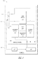
- an adaptive tire system 100 can include a vehicle 102, a vehicle wheel 104 and a bolt actuation system 106.
- the bolt actuation system 106 can include a bolt 108, an extension module 110 and a lock module 112.
- the bolt 108 can be a generally linear member mounted for reciprocal movement along a radial direction of a tire associated with the vehicle wheel 104.
- the bolt 108 can be made from any material. However, metals typically provide for reasonable durability.
- the bolt 108 can be mounted for limited movement within an aperture extending through an outer surface of a tire.
- the bolt 108 can include a distal end and can be mounted such that the distal end of the bolt can be retracted to a position in which it does not protrude beyond an outer surface of a tread of an associated tire and a deployed position in which the distal tip protrudes beyond the outer surface of the surrounding tread.
- the lock module 112 can be configured to move between locked and unlocked positions. Additionally, the locked module can be configured to lock the bolt 108 in a deployed position without the need of persistently maintained actuation force, such as compressed air or another source of force. Rather, the lock mechanism 112 can be configured to mechanically maintain the bolt in the deployed position and optionally without the need for any persistently or continuously applied energy or force.
- the lock module 112 can also be configured to lock the bolt 108 in the retracted position. Again, the lock module 112 can be configured to maintain the bolt in a retracted position without the need for persistently or continuously maintained application of energy or air pressure. Additionally, such functionality of the lock module 112 can prevent the bolts from unintentionally being deployed through centrifugal acceleration caused by movement of the wheel 104 and the associated vehicle 102.
- the extension module 110 can be configured to provide an actuation force for moving the bolt 108 from a retracted position to the deployed position noted above. Any type of actuator can be used. In the embodiments described below with reference to the remaining figures, the extension module 110 utilizes compressed air for actuation of the bolt 108. However, other types of actuators can also be used.
- the system 106 can also include a retract module 114.
- the retract module 114 can be configured to provide an actuation force for moving the bolt 108 from the deployed position to a retracted position.
- the retract module 114 can be in the form of a spring.
- the retract module 114 can also include an active actuator such as a compressed air actuator or other type of actuator for moving the bolt 108 into the retracted position. This can be beneficial where the force of a spring alone is not sufficient to reliably move the bolt fully into the retracted position.
- the retract module 114 can be incorporated into the extension module 110.
- the system 106 can also optionally include an adjustment module 116.
- the adjustment module 116 can be configured to allow the magnitude of protrusion of the bolt 108 from the surrounding tread surface of an associated tire to be adjusted.
- the bolt 108 can be made in one or more parts including a threaded engagement with another component thereby allowing the amount by which the bolt protrudes from the surrounding tire tread to be adjusted in or out.
- the adjustment module 116 can include a mechanism for allowing the tips of the bolt 108 to be removed and replaced.
- the bolt 108 can be made in a plurality of pieces in which the distal-most tip of the bolt 108 is threaded onto an inner portion of the bolt 108 such that the distal tip can be removed and replaced.
- the replaceable tips can be made from any material including, for example, but without limitation, steel, titanium, plastic, aluminum, etc.
- the system 106 can include a manual interface 118 configured to allow a user to manually control the supply of air from an air source 120 to the extension module 110, lock module 112 and the retract module 114.
- the air source 120 can be mounted on the vehicle 102. However, other configurations could also be used.
- the manual interface 118 is mounted on the vehicle wheel 104.
- other configurations can also be used.
- the system 106 can include an automatic control device 122.
- the automatic control device 122 can control the automatic deployment and retraction of the bolt 108.
- the device 122 can be configured, with hard-wired circuitry, a microprocessor/microcontroller, or general purpose computer hardware and actuators for controlling a supply of air from the air source 120 to the extension module 110, lock module 112, and retract module 114.
- the control device 122 can include a user input device (not shown) configured to allow a user to perform a single input command activate for requesting the lock module 112 to unlock the bolt 108 and the extension module 110 to apply an actuation force to move the bolt 108 from the retracted position to the deployed position.
- the device 122 can include a user input device that allows a user to perform a single input command for requesting retraction of the bolt and to activate the lock module 112 and the retract module 114. As such, a user can extend and retract the bolt 108 with single inputs. Other configurations can also be used.
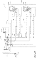
- FIG 2 illustrates a further embodiment of the adaptive tire system 100, identified generally below by the reference numeral 100A.
- the components of the system 100A that are the same or similar to the adaptive system 100 illustrated in Figure 1 are identified with the same reference numeral, except that "A" has been added thereto.
- the description set forth above with regard to the system 100 also applied to the similarly designated components of the system 100A.
- the vehicle 102A is a four-wheeled passenger vehicle having four vehicle wheels 104A.
- the system 100A includes a vehicle mounted air compressor 130 connected to a vehicle-mounted power supply, such as a 12-volt power supply 132.
- the air compressor 130 can be designed to provide at least about 47 psi compressed air.
- an inline 30-amp fuse 134 can be included in the circuit connection 136 to the air compressor 130.
- the air compressor 130 can have a power switch 138 accessible by a user and an air delivery hose 140.
- the delivery hose 140 can be sized so that it can extend to all of the wheels 104A of the vehicle 102A.
- the air delivery hose 140 can include an air shut off insert 142 at its distal end for delivering compressed air to the components within the wheels 104A, described in greater detail below.
- the shut off insert 142 can be any type of shut off insert which are well-known in the art.
- the system 100A can include a plurality of extendable and/or retractable bolts 108A on each of the wheels 104A.
- the bolts 108A can be arranged along a single circumferential line around each of the wheels 104A.
- the bolts 104A are arranged around two circumferential lines, parallel to one another, thereby defining two groups of bolts; an inner set of bolt assemblies 150 and an outer set of bolt assemblies 152.
- the inner and outer bolt assemblies 150, 152 can be configured to be deployed and retracted simultaneously.
- the inner and outer bolt assemblies 150, 152 can be identical or similar to each other. However, other configurations and actuation procedures can also be used.
- FIG 2 schematically illustrates the system 100A including two portions of the wheel 104A; the rigid portion of the wheel 104A referred to herein as wheel 170, also commonly referred to as an "rim" and a tire 172.
- the wheel 170 can include inputs for a user to manually control deployment and retraction of the bolt assemblies 150, 152.
- FIG 2A several components can extend from the wheel 170 into the tire 172 to provide actuation to the bolt assemblies 150, 152.
- the wheel 170 can include one or more pipe couplers 174 configured to receive pressurized air from the shut off insert 142.
- the pipe couplers 174 can be connected to a pressure reservoir 176, which can be in the form of a chamber or loop of pipe or hose. Other configurations can also be used.
- the reservoir 176 can be connected to three valves 178, 180, 182 which are configured to selectively connect the reservoir 176 with either internal air circuits within the tire 172 or a vent reservoir or vent loop 184.
- the vent reservoir 184 is connected to a vent discharge port 186, which can optionally include an outlet filter 188 configured to discharge air from the loop 184 to the atmosphere.
- valves 178, 180, 182 connect the air circuits internal to the tire 172 to the vent loop 182 and thus to the atmosphere. In this position, none of the bolt assemblies 150, 152 can receive any internal actuation forces. In some embodiments, the bolt assemblies 150, 152 are biased towards a retracted, locked state. Thus, with valves 178, 180, 182 in the positions illustrated in Figure 2A , the bolt assemblies 150, 152 would remain in a retracted, locked state. However, other configurations of bolt assemblies 150, 152 can also be used.
- valves 178, 180, 182 are movable to at least one other position.
- the valves 178, 180, 182 are configured to be rotated clockwise by 90 degrees. In that configuration, the valves 178, 180, 182 connect the reservoir 176 with the internal plumbing of the tire 172. Selective actuation in the valves 178, 180, 182 can provide desired locking, unlocking, retraction, and extension of the bolt assemblies 150, 152, described in greater detail below.
- the tire 172 can include a set of inner actuator manifolds 190 and a set of outer actuator manifolds 192.
- the manifolds 190, 192 can be in any configuration and can be configured for supplying any type of actuation force to the inner and outer bolt assemblies 150, 152, respectively.
- the manifold sets 190, 192 include three pneumatic reservoirs or loops corresponding to the three valves 178, 180, 182. More specifically, the manifolds 190, 192 each include an extend manifold 194, a retract manifold 196 and an unlock manifold 198.
- the extend manifolds 194 are connected to the valve 178 with a wheel rim fitting 200.
- the retract and unlock manifold 196, 198 are also connected to valves 180, 182, respectively, with similar wheel rim fittings, unions, and other types of hose or connectors that can be readily applied by one of ordinary skill in the art.
- each of the manifold sets 190, 192 can be connected to a plurality of bolt assemblies 150, 152 in an aligned or offset configuration. In the illustrated embodiment, each of the manifold sets 190, 192 are connected to nine inner and outer bolt assemblies 150, 152, respectively.
- the inner and outer bolt assemblies 150, 152 can comprise bolt actuators.
- Each of these bolt actuators can include a movable bolt 200, an extension actuator device 202, an unlocking device 204 and a retraction device 206.
- each of the extension manifolds 194 are connected to the respective inner and outer extension devices 202 of the inner and outer bolt assemblies 150, 152.
- the extension devices 202 can be diaphragm mechanisms which expand when subjected to pressurized air and thereby generate an actuation force.
- the diaphragms 202 exert a linear, downward force against the movable bolts 200.
- the movable bolts 200 slideably move within the bolt assemblies 150, 152 and are spring biased towards a retracted (upward) position.
- valve 178 when the valve 178 is rotated 90 degrees from a position illustrated in Figure 2A , thereby guiding pressurized air to the manifolds 194, pressurized air enters the diaphragm mechanisms 202 and thereby urges the bolts 200 toward the extended position (phantom line in Figure 2A ),
- the lock mechanism 204 described in greater detail below, must be in an unlocked position before the movable bolts 200 can move.
- the manifolds 196 are connected to the unlock mechanisms 204.
- the unlock mechanism 204 can be in the form of a diaphragm device which, when subjected to pressurized air from manifolds 198, generate an actuation force which presses against a movable locking member (described in greater detail below).
- the locking member can be biased towards a lock position.
- the unlock mechanism 204 can be configured to, when provided with an actuation force, move the locking member toward an unlock position.
- valve 178 first and then valve 182 are rotated 90 degrees from a position illustrated in Figure 2A , thereby providing pressurized air to the manifolds 194, 198, the locking member within the bolt assemblies 150, 152 would be moved to the unlock position and the extend mechanisms 202 would urge the movable bolts 200 to the extended position illustrated in phantom line in Figure 2A .
- the retract manifolds 196 are connected to a retract device 206 in the bolt assemblies 150, 152.
- the retract device 206 in some embodiments, can be incorporated into the extend device, for example, utilizing the same diaphragm to provide a retraction force.
- the retract device 206 can include air passages for communicating air in the retract manifold 196 to the opposite side of the diaphragm used to provide the extension movement performed by the extension device.
- valves 178, 180, 182 can be left in the position illustrated in Figure 2A , where all manifolds 194, 196, 198 are vented to the vent reservoir 184.
- the lock mechanism (described in greater detail below) included in the bolt assemblies 150, 152 lock the movable bolts 200 into an existing position and do not require any continued or persistent application of actuation force or energy.
- a user can manually connect the air supply shut off insert 142 to the coupler 174 and rotate valve 182 90 degrees clockwise from the position illustrated in Figure 2A .
- Such a movement of the valve 182 connects pressurized air within the reservoir 176 with the manifolds 198. Thereafter, pressurized air flows into the unlock mechanisms 204 to thereby unlock the bolts 200 from their position.
- the user can rotate the valve 178 90 degrees clockwise from the position illustrated in Figure 2A to thereby provide pressurized air to the manifolds 194.
- Pressurized air from the manifolds 194 will then flow into the extend mechanisms 202 and thereby urge the bolts 200 from retracted to deployed positions. Thereafter, the user can then rotate the valve 182 counter-clockwise to the position illustrated in Figure 2A , thereby allowing the pressurized air to vent from the unlock mechanisms 204 and thereby allowing the lock mechanism to return to its locked position towards which it is biased. The user can then return the valve 178 to the position illustrated in Figure 2A and disconnect the shut off insert 142.
- the user can move the valve 182 to the unlock position (90 degrees clockwise from the position illustrated in Figure 2A ) and also rotate the valve 180 90 degrees clockwise from the position illustrated in Figure 2A .
- pressurized air will flow into both the unlock manifolds 198 and the retract manifolds 196, thereby urging the bolt 200 towards its retracted position.
- the bolt assemblies 150, 152 can optionally include springs to bias the bolts 200 toward a retracted position. Thus, in some embodiments, of under certain circumstances, it may not be necessary to use the retract valve 180 to retract the bolts.
- Friction between the bolt assembly and lock cams during pressure retraction is minimized by sloped surfaces of bolt assembly and lock cam, described in greater detail below with reference to Figure 27 .
- the user can return the lock valve 182 to the position illustrated in Figure 2A , thereby allowing the pressurized air to bleed out of the unlock mechanisms 204 allowing the lock member (described below) to return to a locked position.
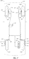
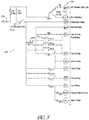
- Figure 3 illustrates a further modification of the systems 100, 100A, identified generally by the reference numeral 100B.
- the components of the system 100B that are not described in detail below can be assume to be the same or similar to those described above with reference to the systems 100, 100A.
- the system 100B can include an automated air delivery subsystem 300.
- the system 300 can include a compressed air source 138 ( Figure 2 ) or another type of source of actuator forces.
- the system 100B also includes rotary union assemblies 302 associated with each of the wheels 104B.
- the rotary union assemblies 302 are configured to divert actuation forces from the system 300 to the wheels 104B by using pivotable actuator lines mounted on the exterior side of the wheels 104B guiding the actuator forces through a rotary union disposed at the hub of the wheels 104B.
- the rotary union assemblies 302 include flexible pneumatic hose bundles 304 which are connected to the system 300, and the source of compressed air disposed therein.
- the pivotable tube bundles 304 associated with the rear axle of the vehicle 102B can include proximal ends 306 that are fixed to the vehicle frame or body.
- the distal ends 308 of the flexible hose bundles 304 can be fixed to rotary union units 310 disposed at the outer sides of each of the wheels 104B.
- the flexible tube bundles 304 pivot, twist and bend to accommodate movement of the wheels 104B.
- the flexible tube bundles 304 associated with the front wheels can include proximal ends 310 mounted to a portion of the suspension of the vehicle 102B near the inner side of the hub of the wheel 104B. These flexible tube bundles 304 can extend around the wheels 104B to rotary union devices 312 disposed on the outer sides of the wheels 104B associated with the front of the vehicle 102B.
- An additional fixed mount 314 can be provided for each side of the vehicle associated with the front wheels for fixing additional lengths of flexible lines connecting the flexible bundles 304 with the system 300. In this configuration, the flexible tube bundles 304 pivot left and right with steering movements of the wheels 104B, and the additional lengths of hose 316 can flex to accommodate the up-and-down movements of the front wheels 104B.
- the system 300 can include an air compressor 138B and a plurality of valves 178B, 180B, 182B, configured for controlling the supply of air for extension, retraction, and unlocking, respectively.
- the subsystem 300 can include actuators (not shown) configured to electronically operate the valves 178B, 180B, 182B. Any type of actuator known in the art can be used for such actuation.
- the subsystem 300 can include a hard-wired controller, a microprocessor controller, a programmable logic controller, or a general purpose computer and processor with an appropriate operating system and software coding for performing any of the functions described above or below.
- the valves 178B, 180B, 182B are linear sliding-type valves which rely on linear actuators for creating and cutting off connections between the various supply and discharge lines.
- the subsystem 300 includes four parallel bundled outputs for feeding actuation air to the rotary unions 310.
- the subsystem 300 can be configured to sequentially operate the valves 178B, 180B, 182B, to perform the functions of retraction and extension.
- the subsystem 300 can be programmed (and/or hard-wired) to respond to a user input, for example, user input device 330 ( Figure 3 ).
- the user input device 330 can include, for example, two or more positions; a first position for requesting retraction and a second position for requesting extension.
- the subsystem can be programmed, as is well within the skill of one in ordinary skill in the art, to perform the following steps upon detection of retraction and extension.
- the subsystem 300 can sequentially move valve 182B to connect the high-pressure source 176B to the unlocked manifold 198B. This will, as described above, unlock the bolt assemblies 150B, 152B. With the value 182B maintained in the activated position noted above, the subsystem 300 can then activate valve 178B to connect the extension manifolds 194B to the bolts 150B, 152B. As such, the movable bolts 200B would then be urged to the extended position (phantom line in Figure 3B ).
- the subsystem 300 can then sequentially deactivate the valves 182B, 178B. More specifically, the subsystem 300 can, with the movable bolts 200B held in the extended position through the continued application of high-pressure air from the compressor 138B through the loop or source 176B, the valve 182B can then be deactivated, i.e., moved to the position illustrated in Figure 3B , so as to allow pressurized air from the unlocking manifold 198B to be vented through the vent 186B and, optionally, filter 188B. Thus, the locking mechanisms within the bolts 150B, 152B, will move, under their bias, to the locked position.
- valve 178B can be deactivated, i.e., moved to the position illustrated in Figure 3B , to allow high-pressure air to vent through the vent 186B and, optionally, filter 188B.
- the subsystem 300 can sequentially operate valves 182B, 180B, to unlock and then retract the moveable bolts 200B. More specifically, upon detection of the retraction request at the user input 330, the subsystem 300 can activate valve 182B, as noted above, to unlock the bolt assemblies 150B, 152B. With the bolt assemblies 150B, 152B, maintained in an unlocked position, the subsystem 300 can then activate valve 180B to thereby connect the retraction manifolds 196B with the loop 176B so as to drive the moveable bolts 200B toward the retracted position.
- the subsystem 300 can move the valve 182B back to the deactivated state, thereby connecting the unlocked manifolds 198B to the vent 186B so as to vent the pressurized air to the atmosphere, optionally through the filter 188B.
- the bolt assemblies 150B, 152B will move to the locked positions, as noted above, under the bias of the locking mechanisms included in the bolt assemblies 150B, 152B.
- the subsystem 300 can optionally deactivate the valve 180B to thereby connect the retraction manifolds 196B with the vent 186B.
- the subsystem 300 can be activated during operation of the vehicle, i.e., during rotation of the wheels 104B.
- large centripetal accelerations are generated and act on the moveable bolts 200B.
- centripetal acceleration can be utilized to assist or entirely perform or apply the necessary actuation forces for moving the moveable bolts 200B from the retracted position to the extended position.
- the use of the rotary unions 310 allow the system to be configured to be operated by an operator of the vehicle from inside the vehicle, without the need to attach exterior pressure lines.
- the rotary unions 310 provide a highly desirable mode of operation which minimizes the need for user manual manipulation of valves, or application of pressurized air.
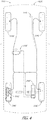
- Figure 4 illustrates yet another modification of the systems 100, 100A, 100B, and is identified generally by the reference numeral 100C.
- the components of the system 100C which are the same or similar to the components of the systems 100, 100A, or 100B, are identified below with the same reference numeral, except that a "C" has been added thereto.
- the system 100C includes internal, hub-mounted rotary unions 310C.
- the rotary unions 310 and 310C are both configured to provide a plurality of compressed air connections through a spinning joint. Additionally, the use of the internal rotary unions 310C avoids the additionally and potentially undesirable appearance of the unions on the outside of the wheels 104C that results from the configuration of the system 100B.
- the subsystems 300 and 300C can include a hard-wired controller 350 configured for activating the valves and performing the methods described above.
- a hard-wired controller 350 configured for activating the valves and performing the methods described above.
- the controller 350 can include a power switch 382 connecting the controller 350 with a power source 354. Wired in the configuration illustrated in Figure 5 , the power switch 352, when closed, powers on the air compressor 130 and the air compressor light 356. Otherwise, the remainder of the controller 350 remains off, until a user activates the button 330.
- the circuit of the controller 350 also includes a flip-flop relay 358.
- the relay flip-flop 358 allows for the controller 350 to automatically switch between retract and extend modes. In the position illustrated in solid line in Figure 5 , the flip-flop relay 358 is in the retract mode.
- the controller 350 sequentially operates the valves 182B and 180B to perform a bolt retraction operation, as described in greater detail below.
- the flip-flop relay 358 moves to the downward position illustrated in phantom line in Figure 5 .
- the extend relay "ER” When the button 330 is depressed with the flip-flop relay 358 in the down position (phantom line), the extend relay "ER” is connected to the power supply along with the unlocked valve “UV”, the unlock timer “UT”, and the timing relay "TR". As such, the controller 350 sequentially operates the valves 182B and 178B to perform an extend operation, described in greater detail below.
- the timing diagrams for unlocking and operating the valves described above with regard to the retraction and extension methods is set forth therein. These timings are examples of timings that can be used with the systems 300, 300C. However, other timing schemes and scenarios can also be used.
- the controller 350 initially energizes the unlock valve "UV" which corresponds to valve 182B ( Figure 3B ). Some time elapses as the air flows through the valve 182B and into the unlock manifold 198B before the bolt assemblies 150B, 152B are fully unlocked.
- the controller 350 waits until t1 seconds has elapsed after the unlocked valve 182B has been energized before energizing either the extend or retract valves 178B, 180B. This allows the lock mechanisms within the bolt assemblies 150B, 152B to reach a fully unlocked state before an attempt is made to move the bolts 200B. Additionally, the controller 350 waits until the extend or retract valves have been energized for at least t2 seconds before de-energizing the lock valve 182B. This ensures that the bolt has made the desired movement before the locking device within the 150B, 152B moves back into a locked position. Finally, the controller 350 waits until t3 seconds has elapsed before venting the extend or retract manifolds 194B 196B.
- the controller 350 accomplishes the delays associated with the durations T1, T2, T3 noted above by using the unlock timer "UT", and the timing relay "'TR". These types of devices are well known in the art and can include adjustment screws for changing the magnitudes of the times t1, t2, and t3 noted above.
- the appropriate magnitudes of the times t1, t2, and t3 can be determined through routine optimization.
- the magnitudes of the times t1, t2, and t3 may be in the range of approximately 600 ms to 2 full seconds. These magnitudes can vary depending on the geometry of different components within the system and thus one set of magnitudes of the times t1, t2, and t3 may not be appropriate for all embodiments. Additionally, methods of operation of the systems 300, 300C are further described with reference to the control routines illustrated Figures 6B 6C .
- Figures 6B and 6C illustrate control routines that can be utilized by the air supply systems 300, 300C illustrated in Figures 3 and 4 where such systems include microprocessor or general purpose computer control. Additionally, the flow charts set forth in Figures 6B and 6C can represent methods of operation that are performed by hard-wired embodiments, such as that illustrated in Figures 5 and 6A above.
- Figure 6B illustrates a subroutine 550 which is configured to extend the moveable bolts 200.
- the subroutine can start operation block S10. After the operation block S10, the subroutine 550 can move on to decision block S12.
- the system 300 can monitor the user input 330, 330C ( Figs. 3 and 4 ) to determine if a user or operator of the associated vehicle 102B, 102C has activated the user input 330, 330C to request an extension operation. If it is determined that an extension request has not been detected, the control routine 550 can return to start block S10.
- control routine 550 can move on to operation block S14.
- an unlock operation can be activated.
- the system 300, 300C can activate valves 182B, to provide pressurized air to the unlock manifolds 198B to thereby begin an unlock operation.
- the control routine 550 can move on to decision block S16.
- it can be determined if the unlock operation has been performed for at least a minimum amount of time, for example, t1 seconds.
- the systems 300 can determine if the valves 182B have been energized or activated for at least the predetermined number of seconds ("t1"). If it is determined that the unlock operation has not been performed for at least the threshold amount of time, the control routine 550 can return to operation block S14 and continue.
- control routine 550 can move on to operation block S18. This portion of the control routine 550 is reflected in the timing diagram of Figure 5B where it is indicated that an unlock begins "(UV energized)", subsequently, the unlock operation reaches 100% and then after a time B, an extension operation begins.
- an extension operation can be activated.
- the systems 300, 300C can activate valves 178B to thereby provide pressurized air to the extend manifolds 194B.
- the moveable bolts 200, 200B will begin to move toward an extended configuration.
- the control routine 550 can move on to decision block S20.
- the control routine 550 can return to operation block S18 and continue. On the other hand, if it is determined that the extend operation has continued for at least t2 seconds, the control routine 550 can move on to operation block S22.
- a lock operation can begin.
- the systems 330 can deenergize valves 178B and then 182B so as to allow locking manifolds 198B to vent to the atmosphere through the vent 186B and optionally the filter 188B.
- the lock mechanism (described in greater detail below) can move back to the locked position towards which it is biased.
- the control routine 550 can move on to decision block S24.
- decision block S24 it is determined if the block activate function has been performed for at least t3 seconds. If it is determined that the activate lock operation has not been performed for at least t3 seconds, then the control routine 550 can return to operation block S22 and continue. On the other hand, if it is determined in operation block S24 that the activate lock operation has not continued for at least t3 seconds, the control routine 550 can move on to operation block S26.
- the extend operation can be deactivated.
- the systems 300 can deenergize valves 178B so as to allow the extend manifolds 194B to vent to the atmosphere.
- the moveable bolts 200, 200B will remain in the locked extended position, however, the pressure will be vented out of the extend manifolds 194B.
- control routine 550 can move on to end block S28, and optionally return to start block S10 and run continuously in that fashion.
- Figure 6C illustrates a control routine 552 which can be utilized by the control systems 300, 300C to retract the moveable bolts 200B.
- the operations and decisions performed within the control routine 552 are essentially the same as those set forth in the control routine 550, except that instead of the extend valves 178B and extend manifolds 194B being pressurized and vented to the atmosphere, the retract valves 180B and retract manifolds 196B are activated and charged with pressurized air then vented to the atmosphere in the same manner that the extend valves and manifolds are operated in the control routine 550.
- the steps S50, S52, S54, S56, S58, S60, S62, S64, S66, and S68 are not described in greater detail herein. Rather, one of ordinary skill in the art can fully understand how the control routine 552 can operate.
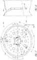
- Figures 6 and 7 illustrate a sample wheel or "rim” 400 that can be used as a center rigid portion of any of the wheels 104, 104A, 104B, 104C.
- the wheels 400 can include a plurality of apertures for accommodating the air circuit tubing and hardware illustrated in Figures 1-4 .
- the wheels 400 can include apertures 402 for accommodating connections from the manual user interface 118 ( Figure 1 ), 170 ( Figure 2A ), or the rotary unions 300, 300C, into the interior of the wheels 104.
- appropriate seals would be used in conjunction with the apertures 402 to maintain an air-tight seal for the wheel 104 for inflation purposes.
- the wheel 400 can include various other apertures not described in greater detail herein, for accommodating other components described below.
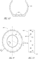
- a tire 500 is illustrated therein as including a tread surface 502, a sidewall 504, and a plurality of apertures 506 for accommodating bolt assemblies 150, 152.
- the apertures 506, in some embodiments, extend through steel belts, commonly used on tires, and vulcanized rubber used on tires. Additionally, the apertures 506 extend through the tread pattern tread surface 502 of the tire 500 so as to provide a clearance for the moveable bolts 200 to retract and extend from the bolt assemblies 150, 152.
- apertures 506 can be spaced apart so as to be positioned at locations which result in continuous engagement of a bolt 200 with a road surface meaning an ice or snow covered; during operation, as the tire 500 rolls over the road surface 501, individual bolts 200 of the bolt assemblies 150 ( Figure 28 ) will come into contact with the road surface 501, then be pulled away from the road surface 501 as a subsequent bolt assembly 150 moves into contact with the road surface 501.
- the tire 500 includes only eighteen apertures 506 for receiving bolt assemblies 150. However, other numbers, greater or fewer, can also be used.
- the steel belt 602 within the tire 500 can be provided with apertures prior to being calendered with the rubber that also forms the outer and inner surfaces of the tire 500.
- the steel belt 602 can be in the form of an axial single ply steel belt, optionally including additional fiberglass layers, which may be biased.
- the belt 602 can have thin steel discs or rings 603 welded to the belt at the desired locations of the apertures 504 ( Figure 9 ).
- the rings 603 can be welded to the belt 602 using precision-timed electric welds, for example at a plurality of weld spots 630 to provide an adequate connection between the wires of the belt 602 and the rings 603.
- the discs 603 can be punched with an aperture of the desired size for mounting the bolt assemblies 150, 152. Punching the discs 603 also cuts the wires forming the underlying belts.
- the welded connection between the belts 602 and the ring-shaped portions of the discs 603 remaining after punching help compensate for the interruption of the wires caused by punching, thereby routing forces between the ends of interrupted wires of the belt 602.
- the discs 630 are about 1 3 ⁇ 4" in diameter and they are punch with a 1" diameter hole. After such reinforcement, the belt 602 can be calendered with rubber to form a component of the tire 500.
- the belt 602 can also be in the form of a radial belt.
- Figure 11G shows a punched disc 630 welded to a segment 632 of a radial belt configuration of the belt 602.
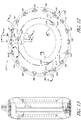
- Figures 12-18 illustrate further modifications of the tire 500 that can be made to accommodate the bolt mechanisms 150, 152, as well as the manifolds 194, 196, 198, 194B, 196B, 198B.
- Figure 11 illustrates 18 installation sites 520 around the tire 500. Additionally, Figure 12 illustrates three connection assemblies 522, 524, 526 for connecting the air interface 118 for control system 122 ( Figure 1 ) as well as the air supply systems 300, 300C to the various manifolds within the tire 500.
- Figures 11 and 12 also illustrate an optional configuration of the manifolds 194, 196, 198, 194B, 196B, 198B within the tire 500.
- references to the various manifolds set forth below will only reference the manifolds 194, 196, 198 but it is understood that the statements apply equally to the manifolds 194B, 196B, 198B.
- the manifolds 194, 196, 198 extend around an inner surface of the tire 500 circumferentially around the tire forming a complete loop therein.
- other configurations can also be used.
- each tire includes an inner set of manifolds 196, 194, 198, and an outer set of manifolds 194, 196, 198.
- the two sets of manifolds allows the installation sites 520 to be staggered along a path along the circumference of the tire 500, alternating between the inside and outside sets of manifolds. Otherwise, each of the installation sites for the bolt assemblies 150, 152, can be identical and are supplied with pressurized air by the two sets of manifolds in the same manner.
- each of the three distribution assemblies 522, 524, 526 can be configured to receive pressurized air from the air distribution system 170 or 300, 300C, or the interface 118 ( Figure 1 ) and to split the air supply so as to provide air both to the inner and outer corresponding manifolds.
- the air distribution assembly 522 provides a connection to the inner and outer locking manifolds 198, thereby allowing pressurized air to be supplied to and vented from the manifolds 198.
- Figures 12 and 17 illustrate how the air distribution assembly 524 is connected to inner and outer retract manifolds 196.
- Figures 12 and 18 illustrate how the distribution assembly 526 is connected to the inner and outer extension manifolds 194. Other arrangements of the manifolds can also be used.
- the air distribution assembly 522 includes an air supply line 523 that extends downwardly from an output of air distribution coupler 530.
- the coupler 530 can be secured to the side wall of the tire 500 in a through hole of the side wall of the tire 500. This provides for secure fixation of the coupler 530 and for support of the supply line 523 within the tire. For example, during rotation of the tire 500, centripetal acceleration causes large forces on the line and coupler 530.
- the fixation of the coupler 530 to the side wall of the tire 500 also provides for accommodation of bends in the tube assemblies 523, 525, and 527 about an axis parallel to the rotational axis of the wheel 104 as well as bends in tube assemblies 523A, 525A, 527A about an axis transverse to the rotational axis of the wheel 104. These bends allow the hoses to flex appropriately as the wheel rotates which causes the tread surface and the bolt assemblies 150, 152 to deflect toward the hub of the wheel 104 and as the wheel is distorted during cornering. Other configurations can also be used.
- the manifolds 194, 196, 198 can be formed along the inner circumferential surface of the tire 500 on the opposite side of the outer tread surface 502.
- the tire 500 can include a vulcanized rubber portion 600 disposed on the inner side of the steel belt 602.
- the vulcanized rubber portion 600 can be formed monolithically with the remaining portions of vulcanized rubber forming the side walls 604, steel belt layer 602, and outer tread 502.
- the portion 600 can be made from one or more separate pieces of material adhered to the inner circumferential surface of the tire 500.
- the portion 600 is also made from vulcanized rubber and bonded to the inner circumferential surface of the tire. Other configurations can also be used.
- the manifolds 194, 196, 198 can be further defined by tube members 604 extending along the inside of the manifolds 194, 196, 198.
- the tube members 604 are all made from the same material such tubing made from polyethylene. Other materials and configurations can also be used.
- the distribution assemblies 522, 524, 526 can be connected to the appropriate corresponding manifolds 194, 196, 198 through the use of manifold connector members 606, 608, 610.
- the three connector blocks 606, 608, 610 can have generally the same configuration except for their corresponding connections to different manifolds.
- connector member 606 is configured to connect the supply line 523 to manifolds 198.
- the connector member 608 is configured to connect the supply line 525 with the manifolds 196.
- connector member 610 is configured to connect the air supply line 527 with the manifolds 194.
- the connector member 606 includes a transverse cross passage 620 that connects with the supply line 523.
- the cross passage 620 extends transversely across the top (as viewed in Figure 16 ) of the manifolds 194, 196, 198. More specifically, the passage 620 is spaced above the manifolds 194, 196, 198 and is separated therefrom by a thickness of the connector member 606.
- the connector member 606 includes cylindrical sections622 which are aligned over the overlap between the passage 620 and the manifolds 198. The cylindrical sections622 can facilitate a connection procedure between the cross passage 620 and the manifold 198.
- a drill can be passed into the cylindrical section622, through the cross passage 620, and into the manifold 198. Then, a separate fastener or plug can be inserted into the cylindrical seclions622, thereby creating a closed, fluidic connection between the cross passage 620 and the manifold 198. Sealed as such, the supply line 523 can supply pressurized air to the manifold 198 but remain isolated from the other manifolds 194, 196.
- other configurations can also be used.
- connection member 608 and 610 include similar features for providing isolated connections between the supply lines 525, 527 and the manifolds 196, 194, respectively.
- Figure 19 illustrates an exploded view of a bolt assembly design which can be utilized for the bolt assemblies 150, 152. Other configurations can also be used.
- the bolt assemblies 150, 152 can include an extension actuator assembly 700, a locking actuator assembly 702 and a retraction actuator assembly 704.
- the moveable bolt 200 is mounted in a bolt carrier 710.
- the moveable bolt 200 can be threadedly engaged with the bolt carrier 710.
- rotational movement of the moveable bolt 200 relative to the bolt carrier 710 allows the moveable bolt 200 to change its axial position relative to the bolt carrier 710, described in greater detail below.
- the actuator 700 can include a flexible diaphragm member 711 fixed between a cap member 712 and an upper portion of the main body 714 of the bolt assemblies 150, 152.
- the diagram member 711 can be made from any material typically used with diaphragm actuators.
- a central portion 716 of the diaphragm member 711 is vertically deflectable (as viewed in Figure 19 ) relative to the cap member 712, the body portion 714, as well as the outer periphery 718 of the diaphragm member 711.
- the central portion 716 of the diaphragm member can be fixed to the upper end 720 of the bolt receiver 710.
- the main body 714 can also include two springs 722, 724 aligned with lateral projections 726, 728 of the bolt receiver 710. Additionally, the bolt receiver 710 is configured to be slideably moveable within the main body 714.
- the springs 722, 724 can be configured and sized to bias the bolt receiver 710 into a retracted position, i.e., an upper-most position within the main body 714.
- One or more passages within the main body 714 can connect the extend and retract manifolds 194, 196 to opposing sides (i.e. above and below) of the diaphragm member 711. More specifically, as noted above, the extend manifold 194 is provided with pressurized air when it is desired to cause the bolts 200 to extend outwardly from the tire.
- internal passages through the base member 520 and the main body 714 can be provided for connecting the extend manifold 194 to the upper side (as viewed in Figure 19 ) of the diaphragm member 711.
- the central portion 716 of the diaphragm member 711 is pushed downwardly away from the cap 712, thereby pressing on the upper portion 720 of the bolt receiver 710, thereby pushing the moveable bolt 200 downwardly into the extended position, against the bias of the springs 722, 724.
- the lock actuator 702 can include a moveable lock member 750 including a piston end 752 and a locking projection 754.
- the lock actuator 702 can also include a spring 756 configured to bias the lock member 750 toward a locked position, described in greater detail below.
- the projection 754 can engage one of two recesses 758, 780 so as to lock the bolts 200 in an extended position (when projection 754 engages recess 780) or a retracted position (when projection 754 engages reces 758).
- the lock actuator 702 can also include a diaphragm assembly 782.
- the diaphragm assembly 782 includes diaphragm member 784 and a cap member 786.
- a locking actuator passage 788 disposed in the main body 714 provides for communication and a reciprocal sliding motion of the lock member 750 relative to the main body 714.
- Air passages 790 in the main body 714 allow for actuation air from the unlock manifold 198 to be guided to a space between the diaphragm member 784 and the cap 786. When air is guided as such, a central portion 792 of the diaphragm member 784 is pressed away from the cap member 786 toward the piston head 752 of the lock member 750.
- the lock member 750 is configured to move along a direction transverse or perpendicular to the radial direction of the tire 500. As such, the movement of the lock member 500 is isolated from the centripetal accelerations generated during rotation of the tire 500 during operation of an associated vehicle. This can help prevent movement of the lock member 750 caused by rotation of the tire 500 during operation.
- Other configurations can also be used.
- the bolt assemblies 150, 152 can also include various brackets 800, 802 and flanges 804, 806 for securing the main body 714 to the tire 500.
- the brackets 800, 802 cooperate with the flanges 804, 806 and threaded fasteners 808 to secure the bolt assembly 150 to a mounting block member 810 which provides for communication between the manifolds 194, 196, 198 and various passages on the base member 520 (described in greater detail below with reference to Figures 20-24 ).
- the brackets 800, 802 can be identical to each other.
- a reinforcing member 812 can be disposed between the steel belt layer 602 and the outer tread layer 502 for enhancing the securement of the bolt assembly 150, 152 to the tire 500.
- the reinforcing member can be made from a thin sheet of Kevlar. In some embodiments, four layers of Kevlar can be used, for example, oriented so that their fibers extend in different directions. Other materials can also be used. Additionally, additional rings and retainers 814 can be used to further secure the bolt assemblies 150, 152 to the tire 500.
- Figures 20-24 illustrate, in greater detail, the base member 520 and the connection block 810, which together can form a base member assembly.
- the connection block 810 as illustrated in Figure 19 , is designed to fit around the tubes 604 which partially define the manifolds 194, 196, 198.
- the tubes 604 can extend partially into or completely through the block 810 to provide for secure airtight engagement.
- the block 810 includes internal circular recess 812 into which the base member 520 can fit.
- the base member 520 also includes internal passages 814, 816 and 818 for communication with the manifolds 194, 196, 198.
- the base member 520 also includes a central passage 820 into which the lower portion of the main body 714 of the bolt assemblies 150, 152 engages the base member 520 for facilitating communication of compressed air in and out of the bolt assemblies 150, 152.
- air passages 814 provide communication between the manifold 198 and the unlock actuator 702.
- the body 520 includes passages 816 for providing communication between the manifold 196 and the actuator 700.
- the base member 520 includes passages 818 for providing communication of compressed air in and out of the actuator 700 for extending the bolts 200.
- the base member 520 can include anti-rotation features for preventing rotation of the base member 520 relative to the tire 500.
- the base member 520 can include external splines or serrations 830 engaged with corresponding internal splines or serrations on the block member 810. With the serrations engaged as such, the block member 810 and the base member 520 can be securely rotationally coupled.
- the base member 520 is rigidly fixed in place and will resist torques that may be applied, for example, when bolts 200 are turned within the bolt receivers 710.
- the base member 520 can include a peripheral lip with an under cut 842 which can be configured to provide enhanced engagement with connectors used to connect the remainder of the bolt assembly 150,152 to the base member.
- the bolt assemblies 150, 152 can include brackets 800, 802 which include ramped inner lips 801, 803 configured to engage the undercut 842 on the base member 520. More specifically, the ramped inner lips 842 can have a shape that is complementary to the undercut 842 to thereby provide a more secure attachment between the main body 714 and the base member 520.
- Figures 26 and 27 further illustrate the components of the bolt assemblies 150, 152 shown in Figure 19 .
- the bolt assemblies 150, 152 can also include a seal assembly 900 which can include a plurality of gland seals and gaskets for providing a sliding airtight seal between the main body 714 of the bolt assemblies 150, 152 and the moveable portions of the bolt itself, which includes the moveable bolt 200 and the bolt receiver 710.
- the gland seal assembly 900 maintains an airtight seal.
- the gland assembly can include an ice wiper device 901 so as to scrape off ice that may accumulate on the outer surface of the bolt 200 as the bolt 200 is retracted, thus protecting the glands disposed within the gland seal assembly 900.
- the moveable bolts 200 can include a bolt body 902, and a replaceable tip portion 904.
- the bolt body 902 can include external threads and the inner surface of the bolt receiver 710 can include internal threads so that the bolt body 902 can be axially adjusted relative to the bolt receiver 710.
- the bolt body 902 can further include a lower recess 906 with internal threads which cooperate with external threads on the removable tip portion 904.
- the removable tip portion 904 can be conveniently removed and replaced. As such, maintenance of such an adaptive tire system can be reduced by providing for inexpensive replacement tips 904.
- the bolt assemblies 150, 152 can include one or more passages 903 configured to aid in maintenance and are particularly useful in adding lubrication.
- the bolt receiver 710 can include one or more apertures 903 connecting the inner recess having internal threads for receiving the external threads of the bolt 200 to the outer surface of the bolt receiver 710.
- lubricants can be disposed in the recess or on an upper end of the bolt 200 and thereafter the bolt 200 can be threaded into the recess of the as such, lubricant can be pressed through the aperture 903 and into the space within the main body 714 and onto the outer surface of the bolt receiver 710, which can thereby assist in lubricating the glands in the gland assembly 900, as well as other services within the main body 714.
- This can be particularly beneficial because such removal and addition of lubrication can be performed from the exterior of the wheel 500. In other words, it is not necessary to remove the tire 500 from its associated rim in order to remove the bolts 200 or add lubricant to the inside of the bolt assembly 150, 152.
- the recess 758 and the projection 754 can include complementarily sloped faces to aid in smooth operation and prevent excessive friction.
- the recess 758 can include opposing lateral faces 757, 759 which are sized and shaped to cooperate with faces 753, 755 of the projection 754.
- the faces 757, 759 are sloped such that the faces 757, 759 are splayed away from each other such that the recess 758 is slightly trough shaped.
- the faces 753, 755 of the projection 754 are sloped such that the projection 754 is slightly wedge-shaped.
- the faces 757, 759 and faces 753, 755 can be selected generally the same angle for example, but without limitation about 7°.
- FIGs 28 and 29 illustrate a fully assembled adaptive wheel 104 (described in more general terms with reference to Figure 1 ).
- the wheel 104 includes the manual interface 118 which incorporates manual valve lever 950 for operating the extend valve 178, lever 952 for operating the valve 180 ( Figure 1 ) and lever 954 for operating the unlock valve 182 ( Figure 1 ).
- the levers 950, 952, 954 can be used to control the flow of compressed air in and out of the bolt assemblies 150, 152.
- certain components such as the supply lines 523, 525, 527 are secured in place partially by the coupling members 522, 524, 526.
- FIGS 30 and 31 show a more detailed view of the valves 178, 180, 182 and their connections to the high-pressure reservoir 176, which is in the form of a loop and the vent reservoir 184 which is also in the form of a loop.
- Each of the loops 176, 184 can be formed with a plurality of tubes and connectors, as is within the skill of one of ordinary skill in the art.
- Figures 32-34 illustrate more detailed views of the flexible pivoting bundles 304 initially described above with reference to Figure 3 of the external unions 310.
- the unit 310 can include a rotary union output assembly 950 and a rotary union input assembly 952.
- the rotary union output assembly 950 is connected to three pneumatic lines within the bundle 304.
- a rotary union output assembly 950 includes three internal channels for politically communicating the pneumatic lines within the bundle 304 to the input assembly 952.
- the input assembly 952 is fixed to the rim of the vehicle wheel 104B and is rotatable relative to the rotary union output assembly 950.
- the structure and operation of rotary unions is well known in the art. Thus, further detail about the internal construction of the rotary union 310 is not described in greater detail herein.
- the manifolds 194, 196, 198 are connected to the vehicle wheel 104B through three fluidic channels that extend from the rotary union output assembly 150 into the rotary union input assembly 952 and can operate whether the vehicle and thus the vehicle wheel 104B is moving or stationary.
- Figures 35 and 36 illustrate more detailed views of the flexible bundles 304 used for the front steerable wheels, initially described above with reference to Figure 3 .
- Figures 37-40 illustrate additional more-detailed views of the internal rotary union units 310C initially described above with reference to Figure 4 .
- the rotary union unit 310C includes a rotary union output assembly 950C and a rotary union input assembly 952C.
- the rotary union unit 310C also connects the manifolds 194, 196, 198 with the various components within the vehicle wheel 104C through three fluidic channels extending from the rotary union output assembly 950C into the rotary union input assembly 952C.
- the rotary union units 300 or 300C include retractable/expandable seals.
- known rotary unions include seals that are in continuous contact with sliding surfaces within the union.
- the rotary union units 300 and 300C are used infrequently; only during extension and retraction operations.
- the rotary union units 300 and 300C are not used when the bolts 200 are held in either the retracted or extended positions.
- By retracting the seals when the rotating union units 300 300C are not being used reduced the wear that would normally occur, thereby dramatically increasing the useful life of the seals.
- the rotary union units 300 or 300C can include any type of actuators for expanding and retracting the seals.
- the seals can be pneumatically or hydraulically operated. Additional benefits can be achieved where the seals are controlled by the same pressurized air used for operating the bolt assemblies 150, 152.
- the units 300 300C can include a pressure intensifier device to expand the seals more rapidly when air pressure is applied to the seals.
- rotary unions include seals sized to fit and seal the stator grooves to the rotary union rotor.
- the rotary union units 300, 300C can include an expandable seal unit configured to be selectively expandable.
- Rotary unions with deflectable sealing lips are known from WO 2012/084412 A1 , inflatable sealing means are disclosed in US3330563 , US 4019552 and JP61169304 .
- the rotary union 300C includes three inputs for connections to the manifolds 178B, 180B and 182B which open into three circumferential stator grooves 961, 962, 964, respectively.
- Seals 966, 968, 970, and 972 surround each of the three grooves 961, 962, 964 and press against both the stator body 974 and the rotor 976 which rotates with the wheels of an associated vehicle.
- Seal 966 is illustrated in Figures 42 and 43 , but it is to be understood that the illustrations and descriptions of seal 966 also apply to seals 968, 970, 972.
- the seals 966, 968, 970, 972 can be configured to be expandable.
- the seals 966, 968, 970, 972 can be in the form of hollow, internal cylindrical cross section donuts made of low friction inert plastic PTFE, sized to fit and seal stator groove, and a few thousandths of an inch larger than rotary union rotor diameter.
- the seals 966, 968, 970, 972 can have a rectangular or square-shaped cross-section.
- the seals 966, 968, 970, 972 can be configured to be inflatable such that the surface 965 at the inner diameter of the seal 966 decreases with inflation, at least enough to make a functional seal against the outer surface 967 of the rotary union rotor.
- the seals 966, 968, 970, 972 can include a molded, threaded metal hollow stem 990 extending beyond the stator external surface when passed through an opening from the stator grooves sufficient for a gasket seal washer (not shown), metal washer 992, and nut 994.
- the seals 966, 968, 970, 972 can also include a metal blade spring 996, which can extend 60 degrees to either side of hollow metal threaded stem 990 to support the seals 966, 968, 970, 972 in the stator seal groove and to reduce contact with the rotor 976 when the seals 966, 968, 970, 972 are not pressurized.
- the blade spring 996 can be within the molded doughnut seal 966, which can have a square or rectangular cross-section. Additionally, the blade spring 996 can be biased so as to press the outer surface 998 of the seal 966 against the inner surface of the stator seal groove 999.
- the units 300, 300C can include a common seal manifold 978 which can be disposed at the stator body 974.
- the manifold can include an input side connected to the manifolds 194B, 196B, 198B with check valves 980, 982, 984, respectively.
- the seals 966, 968, 970, 972 are also pressurized and thereby inflated.
- the seals 966, 968, 970, 972 can be appropriately and timely inflated even if only the unlock and extend manifolds (198B, 194B) are connected to the seal manifold 978.
- the seals 966, 968, 970, 972 can be initially pressurized by a flow of compressed air in the unlock manifold 198B.
- This manifold 198B should always be pressurized first since the bolts 200 should be unlocked first before movement is attempted.
- Pressure to the manifold 978 can be maintained after unlock manifold 198B is vented, by the extend manifold 194B for example, at the end of an extend operation.
- the rotary union units 300, 300C can also include a pressure intensifier 986 configured to intensify the pressure discharged from the check valves 980, 982, 984.
- Output pressure from the intensifier 986 is designed to cause a pressure adequate to pressurize the seals 966, 968, 970, 972 with a typical 8 % to 10 % material compression.
- an embedded flat steel spring can be attached to threaded hollow metal seal stem and can extend 60 degrees either side of seal stem, at the outer diameter of seal internal passage cross section so as to provide support for the seals 966, 968, 970, 972 in the stator grooves 961, 962, 964.
- Pressurized seals are thus exposed to other than minor rotational wear only when one or more of three incoming manifolds 194B, 196B, 198B are pressurized, which being a small (low single digit) percentage of time allows for an inverse increase of seal useful life compared to a continuously functioning compressed seal along with an associated increase in seal and rotary union functional reliability.
- a bleed valve 1000 can be connected to the outputs of check valves 980, 982, 984 so as to slowly bleed pressure from the seal manifold 978.
- pressurized air can bleed from the manifold 978 to allow the seals 966, 968, 970, 972 to deflate and thus retract, as described above.
- a back pressure device 1002 can be provided on the upstream side of the check valves 980, 982, 984 so as to provide additional back pressure during initiation of an operation, to thereby speed the inflation of the seals 966, 968, 970, 972.
Description
- The present application claims priority to
U.S. Provisional Patent Application No. 61/691,076 filed August 20, 2012 U.S. Provisional Patent Application No. 61/691,222 filed August 20, 2012 - The inventions disclosed herein relate to adaptive tire systems such as, for example, tire systems designed to adapt to changing road conditions such as road conditions changing from dry road to ice covered roads.
- Vehicle tires support wheel axle loads on a tread area in contact with a road surface. The sum of contact area of all tires of a vehicle multiplied by inflation pressure of each tire will be equal to the vehicle axle load.
- Coefficients of friction between tread and road surface multiplied by the axle load is the maximum force, parallel to the road surface, that can be applied to the tire contact area by the wheels to stop, accelerate, corner or maintain speed on a grade without tire slippage at the contact between the road and tire. As an example, if a tire tread coefficient of friction is 0.30, and an axle load is 453,6 Kg (1000 pounds), the maximum friction force between the tire and road surface before tire slippage will be 136,08 Kg (300 pounds). If a braking load or an acceleration load, greater than 300 pounds at the tread/road interface is developed, wheel rotation will decrease or increase respectively and when the slippage occurs to some degree, a loss of control may occur.
- Almost all automobiles have brakes and engine capacities sufficient to generate loads that exceed tire friction traction on dry concrete, asphalt, gravel, or dirt. This capacity introduces a responsibility for vehicle operators to use restraint from applying full throttle when accelerating and using maximum braking and steering to maintain safe operation and reasonable service life of tires and vehicle components.
- The coefficient of friction between tires and wet pavement is moderately reduced from dry conditions and requires drivers to use longer stopping distances and lower maximum acceleration values. Driving on wet level, sloped, or curved roads with conventional tires has been found to be manageable by drivers notwithstanding that wet brakes and potential for hydroplaning introduce a need for caution.
- The coefficient of friction between tire tread and ice is so low, however, control of a vehicle on ice covered roads under most conditions at moderate speed is precluded unless surface friction has been increased by sand or chemicals, or unless the tires have been fitted with chains, or studs to develop reactive forces.
- Loss of control on ice is typically evidenced by spinning wheels when initiating motion, locking of wheels when braking, and lack of steering response (e.g. "understeering") due to insufficient friction between the tires and road surface for vehicle traction.
- Tire chains and tire studs function by impressing a fixed-shape chain or stud component into ice by tire tread to develop tractive force which is limited by shear values of ice and geometry of components.
- Some known designs for tires with retractable studs rely on perpetual maintenance of air pressure in order to maintain the associated stud in a deployed position. Additionally, some systems use, and thus can deplete, air within a tire in order to cause movement of a stud, for example, between a retracted and a deployed position.
- An aspect of at least one of the inventions disclosed herein includes the realization that using a locking mechanism which provides a locking engagement of a retractable ice engagement member can avoid problems associated with prior known systems noted above. For example, in some known designs, as noted above, a deployable tire stud is maintained in a deployed position only with a perpetual maintenance of internal pressure. However, as the associated tire rolls across the ground, the studs are pressed against their actuators and the maintained air pressure as well as the associated seals which can cause leakage. Thus, use of such a tire with studs in a deployed position can deplete the system of air thereby failing to maintain the associated studs in a desired deployed position and or requiring periodic replenishment of lost air. Further, some systems rely on the air held within a tire for maintaining such deployed positions of studs as well as for retraction of studs. Thus, repeated extension and retraction of studs can cause an associated tire to lose a sufficient amount of air that the tire pressure will fall below a desired level.
- Thus, in accordance with at least some of the embodiments disclosed herein, an adaptive tire can include a retractable bolt for enhancing traction and a lock mechanism for locking the bolt at least in a deployed position without the need for relying on persistently maintained air pressure to keep the bolt in the deployed position. As such, such a tire can avoid the problems associated with the need for persistently maintained air pressure and the associated leakage that can occur. Further, such a system can avoid the depletion of air pressure within a tire that can result from systems which utilize air pressure within the tire for actuation purposes.
- Another aspect of at least one of the inventions disclosed herein includes the realization that an adaptive tire which includes an air actuation system, can avoid the problems of potentially depleting air pressure within a tire with an air actuation system that is independent of the volume of air within a tire. For example, an adaptive tire can include an air actuation system which utilizes compressed air for moving a bolt from a retracted to a deployed position and such an air system can be configured such that the air actuation system is independent of the air utilized for maintaining the tire in an inflated state for supporting axle load. For example, the air actuation system can have air inputs and optionally outputs that are independent from ports used for inflating the tire.
- Another aspect of at least one of the inventions disclosed herein includes the realization that retractable tire bolts can provide better performance where they are adjustable such that their deployed position can be changed. For example, as the tread of a tire wears down and as the tip of the bolt wears down, the effective protruding distance of a bolt changes. More specifically, as tread is worn down, a bolt will protrude farther from the tire tread. On the other hand, as the tip of a bolt wears down, the bolt will protrude less.
- Thus, in accordance with some of the embodiments disclosed herein, an adaptive tire can include retractable and deployable bolts that have an adjustable length. As such, the length of the bolts and thus the magnitude of the protrusion of the bolt can be adjusted for tread wear, the weight of the vehicle, road conditions including ice type, and other factors,
- Another aspect of at least one of the inventions disclosed herein includes the realization that maintenance, servicing, and repair of adaptive tires which include retractable and deployable bolts can be simplified and reduced in cost by providing such an adaptive tire with replaceable tips for the bolts. For example, when such a tire is used, eventually, the tips of the bolts, regardless of the material, wears down. However, only a small portion of the tip of the bolt is worn down because such systems typically only deploy studs or bolts with a small fraction of an inch of protrusion beyond the surrounding tire tread. Thus, by providing an adaptive tire having bolts or studs with a replaceable tip, the functionality of an adaptive tire can be maintained more easily and at less cost.
- Another aspect of at least one of the inventions disclosed herein includes the realization that an arrangement of valves can be used to control deployment, retraction, and locking of a retractable bolt of an adaptive tire. Further benefits can be achieved by configuring the valves to operate deployment, retraction, and locking with air from a single source.
- Thus, in accordance with at least one of the embodiments disclosed herein, an adaptive tire system includes a plurality of valves mounted on a wheel associated with the tire, wherein the valves of a plurality of tires of an associated vehicle are configured to utilize a single source of compressed air for unlocking, retraction, or deployment of studs which protrude outwardly from an outer surface of the tread of an associated tire.
- Another aspect of at least one of the inventions disclosed herein includes the realization that additional components can be used to automatically control actuation of deployable and retractable tire bolts from a location remote from the wheel, such as from inside the associated vehicle.
- Thus, in accordance with at least one of the embodiments disclosed herein, an adaptive tire system includes a rotary air distribution device configured to guide at least two channels of actuation air from a vehicle body into a spinning wheel of the vehicle. Thus, for example, one such channel could be used for unlocking a tire bolt actuator and the second channel can be used for deploying the bolt.
- In some embodiments, the system includes a remotely operated air supply control device for supplying unlocking and actuating air. For example, such a system can include a user input device, such as a single button or switch disposed in a cockpit of an associate vehicle, the actuation of which is detected by the system and where the system delivers air for unlocking and air for deploying a bolt.
- Another aspect of at least one of the inventions disclosed herein includes the realization that the cost and weight of a system can be beneficially reduced by providing an adaptive tire with a layout of bolts in a configuration such that at least one stud is functionally engaged with a road surface at any one time. In this context, the spacing of the bolts would result in the movement of a tire such that as one bolt becomes functionally disengaged from a road surface, another bolt engages or has been engaged with the road surface, As such, the tire can maintain a functional engagement between a bolt and, for example, an ice covered road surface, while minimizing the number of bolts and actuators and thus the mass and cost of the adaptive tire.
- Another aspect of at least one of the inventions disclosed herein includes the realization that where it is desired to deliver at least two independent channels of actuation energy from a vehicle body to a tire, a multichannel rotary union can be used to deliver actuation energy, for example, pressurized fluid such as air. Thus, in accordance with at least one of the embodiments disclosed herein, an adaptive tire system including retractable and extendable bolts, can include a multichannel rotary union configured to guide at least two independent channels of actuation energy from the vehicle body to the adaptive tire. As such, actuators disposed in the adaptive tire can be controlled from the vehicle for example from within the vehicle without the need to exit the vehicle and or touch the wheel assembly associated with the tire. Further, by providing the actuation energy through a rotary union, there is no need to further connect a source of actuation energy or providing local energy source for the actuators within the tire. Additionally, by providing at least two independent channels of actuation energy, a plurality of different functions can be performed independently of one another.
- Another aspect of at least one of the inventions disclosed herein includes the realization that systems which intermittently use rotary unions for transmitting media and/or energy from the vehicle body to an adaptive tire can be provided with an enhanced useful life by including retractable seals. For example, known rotary unions typically include fixed seals between a stater body and a rotating shaft for transmitting media such as fluids from the stator body into the rotating shaft. The seals which are designed to provide fluid tight seals between the stator body and the rotating shaft, are worn down during rotation of the shaft relative to the stator body. However, there are some systems that do not require an included rotary union to be functional at all times. For example, some known uses for single channel rotary unions include systems for inflating tires of a vehicle by transmitting pressurized air, through a rotary union, into a vehicle wheel and tire for providing inflation air. Such systems could incorporate appropriate valves such that pressurized air does not need to be provided through the Rotary union at all times. Rather, pressurized air can be used only during and operation of inflating or the inflating tires. Thus, the seals within the Rotary union are only used during the operation of inflation or re-inflation.
- At least some of the embodiments of the adaptive tire systems disclosed herein do not require a continuous supply of actuation energy, such as a working fluid, to be delivered to the tire from the vehicle. Rather, some of the systems disclosed herein only require actuation energy during specific operations, such as unlocking, extending, and optionally retracting bolts used for enhancing traction on compromise road services, such as ice covered road services.
- Thus, in either of the two environments of use noted above, as well as other environments of use, wear of the seals of a rotary union can be reduced or slowed by using retractable seals that can be extended during times of operation. At other times, the seals can be retracted to prevent wear of the seals, while the rotary union is not being used for transmitting media, fluid, or energy.
- Thus, in accordance with at least some of the embodiments disclosed herein, a rotary union can include retractable seals. For example, the seals between a stator body and a rotating shaft can be inflatable and deflatable. As such, for example, the seals can be inflated during periods of operation, thereby causing the seals to press against surrounding surfaces thereby creating seals, such as fluid tight seals. During periods of not operation, on the other hand, the seals can be deflated, thereby allowing the outer services to shrink away from surrounding surfaces, thereby preventing the outer surfaces of the seals from pressing against surfaces that slide against them during periods of operation. Other configurations can also be used.
- A more complete understanding of the subject matter may be derived by referring to the detailed description and claims when considered in conjunction with the following figures, wherein like reference numbers refer to similar elements throughout the figures.
-
Figure 1 is a schematic diagram of an adaptive tire system of a vehicle and illustrating a manual control mechanism mounted on the wheel of the associated tire and an optional automatic control system mounted in the vehicle associated with the wheel. -
Figure 2 is a schematic diagram of a vehicle including four adaptive tires, an air compressor, and compressed air distribution devices for facilitating manual operation of the adaptive tires. -
Figure 2A is a schematic diagram illustrating various pneumatic connections and actuators included in the system illustrated inFigure 2 . -
Figure 3 is a schematic diagram of another embodiment of an adaptive tire system of a vehicle incorporating four adaptive tires and external multiple passage rotary unions for providing actuating air to the actuators within each tire. -
Figure 3B is a schematic diagram of the adaptive tire system illustrated inFigure 3 . -
Figure 4 is a schematic diagram of a vehicle including four adaptive tires and an automatic actuation system incorporating internal multiple passage rotary unions for delivery of actuation air to the actuators within the adaptive tires. -
Figure 5 is a schematic circuit diagram illustrating a hard-wired circuit that can be incorporated into the systems forFigures 3 and4 for performing extension and retraction operations. -
Figure 6A is a timing diagram illustrating optional timings for actuation of valves with regard to the methods of retraction and extension that can be performed by the systems ofFigures 3-5 . -
Figure 6B is a now chart illustrating a control routine for bolt extension that can be performed by the air supply systems illustrated inFigures 3-3B . -
Figure 6C is a flow chart illustrating a control routine for bolt retraction that can be utilized by the air supply systems illustrated inFigures 3-3B . -
Figure 7 is a front elevational view of a wheel including apertures configured for accommodating hardware of an adaptive tire system such as those ofFigures 1-4 . -
Figure 8 is a side elevational and partial cross sectional view of the wheel ofFigure 6 taken along line 8-8 ofFigure 7 . -
Figure 9 is a front elevational view of a tire having been modified with a plurality of apertures configured to receive actuators and which extend along two offset circumferential paths along the outer surface of the tire. -
Figure 10 is a cross sectional view of the tire ofFigure 9 , taken along line 9-9. -
Figure 11 is a side elevational view of the tire ofFigure 9 . -
Figure 11A is a layout view of an optional configuration of the steel belt layer included in the tire ofFigure 9 , identified as view 11A-11A inFigure 11D . -
Figure 11B is an enlargement of the plan view identified as a D inFigure 11A . -
Figure 11C is a side view of the steel belt layer ofFigure 11A , in the circular configuration used inside a tire. -
Figure 11D is a side elevational view of the belt ofFigure 11C . -
Figure 11E is a front elevation view of an alternative configuration of the steel belt illustrated inFigures 11A - 11D , having a radial steel belt configuration. -
Figure 11F is a side elevational view of the radial steel belt ofFigure 11E . -
Figure 11G is a plan view of a single section of the radial steel belt ofFigures 11E and 11F . -
Figure 12 is a front elevational view of the tire ofFigure 9 with base members of actuators being installed in the apertures illustrated inFigures 9 and 11 . -
Figure 13 is a side elevational and partial sectional view taken along line 13-13 ofFigure 11 . -
Figure 14 is a sectional view of the tire inFigure 11 taken along line 14-14. -
Figure 15 is a sectional view of the tire inFigure 11 taken along line 15-15. -
Figure 16 is a cross sectional view of the tire ofFigure 11 taken along line 16-16. -
Figure 17 is a cross sectional view of the tire ofFigure 11 taken along line 17-17. -
Figure 18 is a cross sectional view of the tire ofFigure 11 taken along line 18-18. -
Figure 19 is an exploded and partial cutaway view of an actuator and tire including the unlocking, retraction, and deployment air supply lines. -
Figure 20 is a top plan view of a base member assembly of the actuator ofFigure 19 and illustrating connections to three air supply manifolds. -
Figure 21 is a side view of the base member assembly illustrated inFigure 20 . -
Figure 22 is a sectional view of the base member illustrated inFigure 20 , taken a long line 22-22. -
Figure 23 is a sectional view of the base member illustrated inFigure 20 , taken along line 23-23. -
Figure 24 is a sectional view of the base member ofFigure 20 taken along line 24-24 ofFigure 25 . -
Figure 25 is a front view of the base member removed from the base member assembly ofFigure 20 . -
Figure 26 is a schematic sectional view of the actuator ofFigure 19 in an assembled state and illustrating a retracted position of the bolt (solid line) and a deployed position of the bolt (phantom line). -
Figure 27 is another schematic sectional view of the actuator ofFigure 19 illustrating a locked position of the locking member with the bolt in a retracted position (solid line). -
Figure 28 is a front elevational view of a combined tire and wheel assembly including actuators shown in phantom and manually operated valves for controlling the supply of actuation air to the actuators for deployment, retraction, and locking which can be incorporated into the systems ofFigures 1 and2 . -
Figure 29 is a sectional view of the tire illustrated inFigure 28 , taken along line 29-29. -
Figure 30 is a rear elevational view of a control unit at hub of the wheel ofFigure 29 illustrating valve bodies and various connections of the air supply system. -
Figure 31 is a front elevational view of a control unit at hub the wheel ofFigure 30 showing the levers for manually operating the valves illustrated inFigure 30 . -
Figure 32 is a top plan and partial sectional view of an adaptive tire with a non-steered tube bundle support assembly and an external rotary union of the system illustrated inFigure 3 and3B . -
Figure 33 is a side elevational view of the external rotary union illustrated inFigure 32 . -
Figure 34 is a cross sectional view of a portion of the assembly illustrated inFigure 32 , taken along the line 34-34. -
Figure 35 is a top plan and partial sectional view of an adaptive tire with a steered tube bundle support assembly (e.g. a front wheel) and including an external rotary union of the system illustrated inFigure 3 -
Figure 36 is a side elevational view of the external union illustrated inFigure 35 . -
Figure 37 is a top plan view of an internal rotary union unit that can be used with the system ofFigure 4 . -
Figure 38 is an end view of the internal rotary union ofFigure 37 . -
Figure 39 is a partial sectional view of the internal rotary union ofFigure 37 , taken along line 39-39. -
Figure 40 is another sectional view of the internal rotary union ofFigure 37 , taken along line 40-40. -
Figure 41 is a schematic diagram of the rotary union ofFigure 37 for supplying three channels of actuation air to an adaptive tire. -
Figure 42 is a schematic cross-sectional view of a seal that can be incorporated into the rotary unions illustrated inFigures 32 - 41 , with the seal in a retracted state. -
Figure 43 is another schematic cross-sectional view of the seal ofFigure 42 , with the seal in an extended state. - The following detailed description is merely illustrative in nature and is not intended to limit the embodiments of the subject matter or the application and uses of such embodiments. As used herein, the word "exemplary" means "serving as an example, instance, or illustration." Any implementation described herein as exemplary is not necessarily to be construed as preferred or advantageous over other implementations. Furthermore, there is no intention to be bound by any expressed or implied theory presented in the preceding technical field, background, brief summary or the following detailed description.
- "Coupled" - The following description refers to parts, devices, mechanisms or features being "coupled" together. As used herein, unless expressly stated otherwise, "coupled" means that one part/device/mechanism/feature is directly or indirectly joined to (or directly or indirectly communicates with) another part/device/mechanism/feature.
- "Adjust" - Some elements, components, and/or features are described as being adjustable or adjusted. As used herein, unless expressly stated otherwise, "adjust" means to position, modify, alter, or dispose an element or component or portion thereof as suitable to the circumstance and embodiment. In certain cases, the element or component, or portion thereof, can remain in an unchanged position, state, and/or condition as a result of adjustment, if appropriate or desirable for the embodiment under the circumstances. In some cases, the element or component, can be altered, changed, or modified to a new position, state, and/or condition as a result of adjustment, if appropriate or desired.
- In addition, certain terminology may also be used in the following description for the purpose of reference only, and thus are not intended to be limiting. For example, terms such as "upper", "lower", "above", and "below" refer to directions in the drawings to which reference is made. Terms such as "front", "back", "rear", and "side" describe the orientation and/or location of portions of the component within a consistent but arbitrary frame of reference which is made clear by reference to the text and the associated drawings describing the component under discussion. Such terminology may include the words specifically mentioned above, derivatives thereof, and words of similar import. Similarly, the terms "first", "second", and other such numerical terms referring to structures do not imply a sequence or order unless clearly indicated by the context.
- The inventions disclosed herein are described in the context of adaptive tire systems used for improving traction of wheeled vehicles on ice covered roads. Some of the embodiments are described in the context of four-wheeled passenger vehicles. However, the inventions disclosed herein can be used in other contexts as well, for example, but without limitation, trucks, multi-wheel axle trucks, tractor trailers, farm vehicles, recreational off road vehicles, robotics, drone vehicles, etc.
- With reference to
Figure 1 , anadaptive tire system 100 can include avehicle 102, avehicle wheel 104 and abolt actuation system 106. - The
bolt actuation system 106 can include abolt 108, anextension module 110 and alock module 112. Thebolt 108 can be a generally linear member mounted for reciprocal movement along a radial direction of a tire associated with thevehicle wheel 104. Thebolt 108 can be made from any material. However, metals typically provide for reasonable durability. With regard to the reciprocal mounting of thebolt 108, thebolt 108 can be mounted for limited movement within an aperture extending through an outer surface of a tire. More specifically, thebolt 108 can include a distal end and can be mounted such that the distal end of the bolt can be retracted to a position in which it does not protrude beyond an outer surface of a tread of an associated tire and a deployed position in which the distal tip protrudes beyond the outer surface of the surrounding tread. - The
lock module 112 can be configured to move between locked and unlocked positions. Additionally, the locked module can be configured to lock thebolt 108 in a deployed position without the need of persistently maintained actuation force, such as compressed air or another source of force. Rather, thelock mechanism 112 can be configured to mechanically maintain the bolt in the deployed position and optionally without the need for any persistently or continuously applied energy or force. - Optionally, the
lock module 112 can also be configured to lock thebolt 108 in the retracted position. Again, thelock module 112 can be configured to maintain the bolt in a retracted position without the need for persistently or continuously maintained application of energy or air pressure. Additionally, such functionality of thelock module 112 can prevent the bolts from unintentionally being deployed through centrifugal acceleration caused by movement of thewheel 104 and the associatedvehicle 102. - The
extension module 110 can be configured to provide an actuation force for moving thebolt 108 from a retracted position to the deployed position noted above. Any type of actuator can be used. In the embodiments described below with reference to the remaining figures, theextension module 110 utilizes compressed air for actuation of thebolt 108. However, other types of actuators can also be used. - Optionally, the
system 106 can also include a retract module 114. The retract module 114 can be configured to provide an actuation force for moving thebolt 108 from the deployed position to a retracted position. In some embodiments, the retract module 114 can be in the form of a spring. Thus, when thelock mechanism 112 is unlocked, and there is no actuation force provided by theextension module 110, the retract module 114 can return the bolt to the retracted position by action of a spring. Optionally, the retract module 114 can also include an active actuator such as a compressed air actuator or other type of actuator for moving thebolt 108 into the retracted position. This can be beneficial where the force of a spring alone is not sufficient to reliably move the bolt fully into the retracted position. In some embodiments, the retract module 114 can be incorporated into theextension module 110. - The
system 106 can also optionally include anadjustment module 116. Theadjustment module 116 can be configured to allow the magnitude of protrusion of thebolt 108 from the surrounding tread surface of an associated tire to be adjusted. For example, thebolt 108 can be made in one or more parts including a threaded engagement with another component thereby allowing the amount by which the bolt protrudes from the surrounding tire tread to be adjusted in or out. Further, theadjustment module 116 can include a mechanism for allowing the tips of thebolt 108 to be removed and replaced. For example, thebolt 108 can be made in a plurality of pieces in which the distal-most tip of thebolt 108 is threaded onto an inner portion of thebolt 108 such that the distal tip can be removed and replaced. In some embodiments, the replaceable tips can be made from any material including, for example, but without limitation, steel, titanium, plastic, aluminum, etc. - Optionally, the
system 106 can include amanual interface 118 configured to allow a user to manually control the supply of air from anair source 120 to theextension module 110,lock module 112 and the retract module 114. - In some embodiments, the
air source 120 can be mounted on thevehicle 102. However, other configurations could also be used. - Further, in the illustrated embodiment, the
manual interface 118 is mounted on thevehicle wheel 104. However, other configurations can also be used. - In some embodiments, the
system 106 can include anautomatic control device 122. For example, theautomatic control device 122 can control the automatic deployment and retraction of thebolt 108. For example, thedevice 122 can be configured, with hard-wired circuitry, a microprocessor/microcontroller, or general purpose computer hardware and actuators for controlling a supply of air from theair source 120 to theextension module 110,lock module 112, and retract module 114. In some embodiments, thecontrol device 122 can include a user input device (not shown) configured to allow a user to perform a single input command activate for requesting thelock module 112 to unlock thebolt 108 and theextension module 110 to apply an actuation force to move thebolt 108 from the retracted position to the deployed position. Similarly, and optionally, thedevice 122 can include a user input device that allows a user to perform a single input command for requesting retraction of the bolt and to activate thelock module 112 and the retract module 114. As such, a user can extend and retract thebolt 108 with single inputs. Other configurations can also be used. -
Figure 2 illustrates a further embodiment of theadaptive tire system 100, identified generally below by thereference numeral 100A. The components of thesystem 100A that are the same or similar to theadaptive system 100 illustrated inFigure 1 are identified with the same reference numeral, except that "A" has been added thereto. The description set forth above with regard to thesystem 100 also applied to the similarly designated components of thesystem 100A. - In the illustrated embodiment, the
vehicle 102A is a four-wheeled passenger vehicle having fourvehicle wheels 104A. - The
system 100A includes a vehicle mountedair compressor 130 connected to a vehicle-mounted power supply, such as a 12-volt power supply 132. In some embodiments, theair compressor 130 can be designed to provide at least about 47 psi compressed air. In some embodiments, an inline 30-amp fuse 134 can be included in thecircuit connection 136 to theair compressor 130. Theair compressor 130 can have apower switch 138 accessible by a user and anair delivery hose 140. Thedelivery hose 140 can be sized so that it can extend to all of thewheels 104A of thevehicle 102A. Theair delivery hose 140 can include an air shut offinsert 142 at its distal end for delivering compressed air to the components within thewheels 104A, described in greater detail below. The shut offinsert 142 can be any type of shut off insert which are well-known in the art. - Similarly to the
system 100,Figure 1 , thesystem 100A can include a plurality of extendable and/orretractable bolts 108A on each of thewheels 104A. Thebolts 108A can be arranged along a single circumferential line around each of thewheels 104A. In the illustrated embodiment, thebolts 104A are arranged around two circumferential lines, parallel to one another, thereby defining two groups of bolts; an inner set ofbolt assemblies 150 and an outer set ofbolt assemblies 152. The inner andouter bolt assemblies outer bolt assemblies -
Figure 2 schematically illustrates thesystem 100A including two portions of thewheel 104A; the rigid portion of thewheel 104A referred to herein aswheel 170, also commonly referred to as an "rim" and atire 172. Thewheel 170 can include inputs for a user to manually control deployment and retraction of thebolt assemblies Figure 2A , several components can extend from thewheel 170 into thetire 172 to provide actuation to thebolt assemblies - With continued reference to
Figure 2A , thewheel 170 can include one ormore pipe couplers 174 configured to receive pressurized air from the shut offinsert 142. Thepipe couplers 174 can be connected to apressure reservoir 176, which can be in the form of a chamber or loop of pipe or hose. Other configurations can also be used. Thereservoir 176 can be connected to threevalves reservoir 176 with either internal air circuits within thetire 172 or a vent reservoir orvent loop 184. Thevent reservoir 184 is connected to avent discharge port 186, which can optionally include anoutlet filter 188 configured to discharge air from theloop 184 to the atmosphere. - In the orientations illustrated in
Figure 2A , all of thevalves tire 172 to thevent loop 182 and thus to the atmosphere. In this position, none of thebolt assemblies bolt assemblies valves Figure 2A , thebolt assemblies bolt assemblies - The
valves valves valves reservoir 176 with the internal plumbing of thetire 172. Selective actuation in thevalves bolt assemblies - With continued reference to
Figure 2A , thetire 172 can include a set ofinner actuator manifolds 190 and a set of outer actuator manifolds 192. Themanifolds outer bolt assemblies valves manifolds manifold 194, a retractmanifold 196 and anunlock manifold 198. - The extend
manifolds 194 are connected to thevalve 178 with a wheel rim fitting 200. Similarly, the retract and unlock manifold 196, 198 are also connected tovalves - The
manifolds tire 172, parallel to each other. Further, optionally, each of the manifold sets 190, 192 can be connected to a plurality ofbolt assemblies outer bolt assemblies - With continued reference to
Figure 2A , the inner andouter bolt assemblies movable bolt 200, anextension actuator device 202, an unlockingdevice 204 and aretraction device 206. - Each of the extension manifolds 194 are connected to the respective inner and
outer extension devices 202 of the inner andouter bolt assemblies extension devices 202 can be diaphragm mechanisms which expand when subjected to pressurized air and thereby generate an actuation force. In the illustrated embodiment, thediaphragms 202 exert a linear, downward force against themovable bolts 200. As described in greater detail below, themovable bolts 200 slideably move within thebolt assemblies valve 178 is rotated 90 degrees from a position illustrated inFigure 2A , thereby guiding pressurized air to themanifolds 194, pressurized air enters thediaphragm mechanisms 202 and thereby urges thebolts 200 toward the extended position (phantom line inFigure 2A ), However, thelock mechanism 204, described in greater detail below, must be in an unlocked position before themovable bolts 200 can move. - The
manifolds 196 are connected to theunlock mechanisms 204. Similarly to the extendmechanisms 202, theunlock mechanism 204 can be in the form of a diaphragm device which, when subjected to pressurized air frommanifolds 198, generate an actuation force which presses against a movable locking member (described in greater detail below). In some embodiments, the locking member can be biased towards a lock position. Thus, theunlock mechanism 204 can be configured to, when provided with an actuation force, move the locking member toward an unlock position. Thus, ifvalve 178 first and thenvalve 182 are rotated 90 degrees from a position illustrated inFigure 2A , thereby providing pressurized air to themanifolds bolt assemblies mechanisms 202 would urge themovable bolts 200 to the extended position illustrated in phantom line inFigure 2A . - The retract
manifolds 196 are connected to a retractdevice 206 in thebolt assemblies device 206, in some embodiments, can be incorporated into the extend device, for example, utilizing the same diaphragm to provide a retraction force. For example, the retractdevice 206 can include air passages for communicating air in the retract manifold 196 to the opposite side of the diaphragm used to provide the extension movement performed by the extension device. - In operation, with
removable bolts 200 in either the deployed or retracted position, thevalves Figure 2A , where allmanifolds vent reservoir 184. As such, the lock mechanism (described in greater detail below) included in thebolt assemblies movable bolts 200 into an existing position and do not require any continued or persistent application of actuation force or energy. - If a user wishes to change the position of the
movable bolt 200, a user can manually connect the air supply shut offinsert 142 to thecoupler 174 and rotatevalve 182 90 degrees clockwise from the position illustrated inFigure 2A . Such a movement of thevalve 182 connects pressurized air within thereservoir 176 with themanifolds 198. Thereafter, pressurized air flows into theunlock mechanisms 204 to thereby unlock thebolts 200 from their position. If thebolts 200 are in the retracted position, the user can rotate thevalve 178 90 degrees clockwise from the position illustrated inFigure 2A to thereby provide pressurized air to themanifolds 194. Pressurized air from themanifolds 194 will then flow into the extendmechanisms 202 and thereby urge thebolts 200 from retracted to deployed positions. Thereafter, the user can then rotate thevalve 182 counter-clockwise to the position illustrated inFigure 2A , thereby allowing the pressurized air to vent from theunlock mechanisms 204 and thereby allowing the lock mechanism to return to its locked position towards which it is biased. The user can then return thevalve 178 to the position illustrated inFigure 2A and disconnect the shut offinsert 142. - On the other hand, if the
bolts 200 are in the deployed position or extended position and the user desires to retract thebolts 200, the user can move thevalve 182 to the unlock position (90 degrees clockwise from the position illustrated inFigure 2A ) and also rotate thevalve 180 90 degrees clockwise from the position illustrated inFigure 2A . As such, pressurized air will flow into both the unlock manifolds 198 and the retractmanifolds 196, thereby urging thebolt 200 towards its retracted position. As noted above, thebolt assemblies bolts 200 toward a retracted position. Thus, in some embodiments, of under certain circumstances, it may not be necessary to use the retractvalve 180 to retract the bolts. Friction between the bolt assembly and lock cams during pressure retraction is minimized by sloped surfaces of bolt assembly and lock cam, described in greater detail below with reference toFigure 27 . Finally, in order to maintain thebolts 200 in the retracted position, the user can return thelock valve 182 to the position illustrated inFigure 2A , thereby allowing the pressurized air to bleed out of theunlock mechanisms 204 allowing the lock member (described below) to return to a locked position. -
Figure 3 illustrates a further modification of thesystems embodiments systems - With continued reference to
Figure 3 , the system 100B can include an automatedair delivery subsystem 300. Thesystem 300 can include a compressed air source 138 (Figure 2 ) or another type of source of actuator forces. - The system 100B also includes
rotary union assemblies 302 associated with each of the wheels 104B. Therotary union assemblies 302 are configured to divert actuation forces from thesystem 300 to the wheels 104B by using pivotable actuator lines mounted on the exterior side of the wheels 104B guiding the actuator forces through a rotary union disposed at the hub of the wheels 104B. More specifically, with continued reference toFigure 3 , therotary union assemblies 302 include flexible pneumatic hose bundles 304 which are connected to thesystem 300, and the source of compressed air disposed therein. The pivotable tube bundles 304 associated with the rear axle of the vehicle 102B can include proximal ends 306 that are fixed to the vehicle frame or body. The distal ends 308 of theflexible hose bundles 304 can be fixed torotary union units 310 disposed at the outer sides of each of the wheels 104B. During operation, as the wheels 104B move up and down, theflexible tube bundles 304 pivot, twist and bend to accommodate movement of the wheels 104B. - The
flexible tube bundles 304 associated with the front wheels can include proximal ends 310 mounted to a portion of the suspension of the vehicle 102B near the inner side of the hub of the wheel 104B. Theseflexible tube bundles 304 can extend around the wheels 104B torotary union devices 312 disposed on the outer sides of the wheels 104B associated with the front of the vehicle 102B. An additionalfixed mount 314 can be provided for each side of the vehicle associated with the front wheels for fixing additional lengths of flexible lines connecting theflexible bundles 304 with thesystem 300. In this configuration, theflexible tube bundles 304 pivot left and right with steering movements of the wheels 104B, and the additional lengths ofhose 316 can flex to accommodate the up-and-down movements of the front wheels 104B. - As shown in
Figure 3B , the system 300 (Figure 3 ) can include anair compressor 138B and a plurality ofvalves 178B, 180B, 182B, configured for controlling the supply of air for extension, retraction, and unlocking, respectively. Thesubsystem 300 can include actuators (not shown) configured to electronically operate thevalves 178B, 180B, 182B. Any type of actuator known in the art can be used for such actuation. For example, thesubsystem 300 can include a hard-wired controller, a microprocessor controller, a programmable logic controller, or a general purpose computer and processor with an appropriate operating system and software coding for performing any of the functions described above or below. In some embodiments, thevalves 178B, 180B, 182B, are linear sliding-type valves which rely on linear actuators for creating and cutting off connections between the various supply and discharge lines. - As reflected in
Figure 3B , thesubsystem 300 includes four parallel bundled outputs for feeding actuation air to therotary unions 310. - With continued reference to
Figure 3B , thesubsystem 300 can be configured to sequentially operate thevalves 178B, 180B, 182B, to perform the functions of retraction and extension. For example, thesubsystem 300 can be programmed (and/or hard-wired) to respond to a user input, for example, user input device 330 (Figure 3 ). Theuser input device 330 can include, for example, two or more positions; a first position for requesting retraction and a second position for requesting extension. - The subsystem can be programmed, as is well within the skill of one in ordinary skill in the art, to perform the following steps upon detection of retraction and extension.
- When the
user input 330 is actuated to request extension, thesubsystem 300 can sequentially movevalve 182B to connect the high-pressure source 176B to the unlocked manifold 198B. This will, as described above, unlock thebolt assemblies 150B, 152B. With thevalue 182B maintained in the activated position noted above, thesubsystem 300 can then activate valve 178B to connect the extension manifolds 194B to thebolts 150B, 152B. As such, the movable bolts 200B would then be urged to the extended position (phantom line inFigure 3B ). - The
subsystem 300 can then sequentially deactivate thevalves 182B, 178B. More specifically, thesubsystem 300 can, with the movable bolts 200B held in the extended position through the continued application of high-pressure air from thecompressor 138B through the loop or source 176B, thevalve 182B can then be deactivated, i.e., moved to the position illustrated inFigure 3B , so as to allow pressurized air from the unlocking manifold 198B to be vented through the vent 186B and, optionally, filter 188B. Thus, the locking mechanisms within thebolts 150B, 152B, will move, under their bias, to the locked position. After thebolts 150B, 152B, change state to the locked state, the valve 178B can be deactivated, i.e., moved to the position illustrated inFigure 3B , to allow high-pressure air to vent through the vent 186B and, optionally, filter 188B. - On the other hand, if the
bolts 150B, 152B, are in the extended position and a retraction request is detected at theuser input 330, thesubsystem 300 can sequentially operatevalves 182B, 180B, to unlock and then retract the moveable bolts 200B. More specifically, upon detection of the retraction request at theuser input 330, thesubsystem 300 can activatevalve 182B, as noted above, to unlock thebolt assemblies 150B, 152B. With thebolt assemblies 150B, 152B, maintained in an unlocked position, thesubsystem 300 can then activate valve 180B to thereby connect the retraction manifolds 196B with the loop 176B so as to drive the moveable bolts 200B toward the retracted position. - After the moveable bolts 200B have been moved to the retracted position, the
subsystem 300, while maintaining valve 180B in the activated state, can move thevalve 182B back to the deactivated state, thereby connecting the unlocked manifolds 198B to the vent 186B so as to vent the pressurized air to the atmosphere, optionally through the filter 188B. - As such, the
bolt assemblies 150B, 152B, will move to the locked positions, as noted above, under the bias of the locking mechanisms included in thebolt assemblies 150B, 152B. - Thereafter, the
subsystem 300 can optionally deactivate the valve 180B to thereby connect the retraction manifolds 196B with the vent 186B. - With regard to the function of extension of the moveable bolts 200B, the
subsystem 300 can be activated during operation of the vehicle, i.e., during rotation of the wheels 104B. As such, during operation, large centripetal accelerations are generated and act on the moveable bolts 200B. Thus, such centripetal acceleration can be utilized to assist or entirely perform or apply the necessary actuation forces for moving the moveable bolts 200B from the retracted position to the extended position. - The use of the
rotary unions 310 allow the system to be configured to be operated by an operator of the vehicle from inside the vehicle, without the need to attach exterior pressure lines. Thus, therotary unions 310 provide a highly desirable mode of operation which minimizes the need for user manual manipulation of valves, or application of pressurized air. -
Figure 4 illustrates yet another modification of thesystems systems - With continued reference to
Figure 4 , the system 100C includes internal, hub-mountedrotary unions 310C. Therotary unions rotary unions 310C avoids the additionally and potentially undesirable appearance of the unions on the outside of the wheels 104C that results from the configuration of the system 100B. - With reference to
Figure 5 , thesubsystems 300 and 300C can include a hard-wiredcontroller 350 configured for activating the valves and performing the methods described above. Some of the components are identified with functional block representations and such components' construction, and operation thereof, is well understood by those of ordinary skill in the art. Additionally, a more detailed description of the components and operation of thecontroller 350 ofFigure 5 is set forth inU.S. Provisional Patent Application No. 61/691,076 filed August 20, 2012 U.S. Provisional Patent Application No. 61/691,222 filed August 20, 2012 - As shown in
Figure 5 , thecontroller 350 can include a power switch 382 connecting thecontroller 350 with apower source 354. Wired in the configuration illustrated inFigure 5 , thepower switch 352, when closed, powers on theair compressor 130 and theair compressor light 356. Otherwise, the remainder of thecontroller 350 remains off, until a user activates thebutton 330. - The circuit of the
controller 350 also includes a flip-flop relay 358. The relay flip-flop 358 allows for thecontroller 350 to automatically switch between retract and extend modes. In the position illustrated in solid line inFigure 5 , the flip-flop relay 358 is in the retract mode. Thus, when thebutton 330 is depressed, the retract relay "RR" as well as the unlock valve "UV", the unlock timer "UT", and the timing relay "TR" are connected to thepower supply 354. As such, thecontroller 350 sequentially operates thevalves 182B and 180B to perform a bolt retraction operation, as described in greater detail below. At the end of the retraction operation, the flip-flop relay 358 moves to the downward position illustrated in phantom line inFigure 5 . - When the
button 330 is depressed with the flip-flop relay 358 in the down position (phantom line), the extend relay "ER" is connected to the power supply along with the unlocked valve "UV", the unlock timer "UT", and the timing relay "TR". As such, thecontroller 350 sequentially operates thevalves 182B and 178B to perform an extend operation, described in greater detail below. - With regard to
Figure 5 , the timing diagrams for unlocking and operating the valves described above with regard to the retraction and extension methods, is set forth therein. These timings are examples of timings that can be used with thesystems 300, 300C. However, other timing schemes and scenarios can also be used. As reflected in the timing diagram ofFigures 6A , during operation, thecontroller 350 initially energizes the unlock valve "UV" which corresponds tovalve 182B (Figure 3B ). Some time elapses as the air flows through thevalve 182B and into the unlock manifold 198B before thebolt assemblies 150B, 152B are fully unlocked. Thus, thecontroller 350 waits until t1 seconds has elapsed after theunlocked valve 182B has been energized before energizing either the extend or retract valves 178B, 180B. This allows the lock mechanisms within thebolt assemblies 150B, 152B to reach a fully unlocked state before an attempt is made to move the bolts 200B. Additionally, thecontroller 350 waits until the extend or retract valves have been energized for at least t2 seconds before de-energizing thelock valve 182B. This ensures that the bolt has made the desired movement before the locking device within the 150B, 152B moves back into a locked position. Finally, thecontroller 350 waits until t3 seconds has elapsed before venting the extend or retract manifolds 194B 196B. Thecontroller 350 accomplishes the delays associated with the durations T1, T2, T3 noted above by using the unlock timer "UT", and the timing relay "'TR". These types of devices are well known in the art and can include adjustment screws for changing the magnitudes of the times t1, t2, and t3 noted above. The appropriate magnitudes of the times t1, t2, and t3 can be determined through routine optimization. The magnitudes of the times t1, t2, and t3 may be in the range of approximately 600 ms to 2 full seconds. These magnitudes can vary depending on the geometry of different components within the system and thus one set of magnitudes of the times t1, t2, and t3 may not be appropriate for all embodiments. Additionally, methods of operation of thesystems 300, 300C are further described with reference to the control routines illustratedFigures 6B 6C . -
Figures 6B and 6C illustrate control routines that can be utilized by theair supply systems 300, 300C illustrated inFigures 3 and4 where such systems include microprocessor or general purpose computer control. Additionally, the flow charts set forth inFigures 6B and 6C can represent methods of operation that are performed by hard-wired embodiments, such as that illustrated inFigures 5 and6A above. -
Figure 6B illustrates asubroutine 550 which is configured to extend themoveable bolts 200. The subroutine can start operation block S10. After the operation block S10, thesubroutine 550 can move on to decision block S12. - In the decision block S12, it is determined whether an extension request has been detected. For example, the
system 300 can monitor theuser input Figs. 3 and4 ) to determine if a user or operator of the associated vehicle 102B, 102C has activated theuser input control routine 550 can return to start block S10. - On the other hand, if it determined, in the decision block S12, that a user has requested an extension operation, the
control routine 550 can move on to operation block S14. - In the operation block S14, an unlock operation can be activated. For example, the
system 300, 300C can activatevalves 182B, to provide pressurized air to the unlock manifolds 198B to thereby begin an unlock operation. After the operation block S14, thecontrol routine 550 can move on to decision block S16. In the operation block S16, it can be determined if the unlock operation has been performed for at least a minimum amount of time, for example, t1 seconds. For example, thesystems 300 can determine if thevalves 182B have been energized or activated for at least the predetermined number of seconds ("t1"). If it is determined that the unlock operation has not been performed for at least the threshold amount of time, thecontrol routine 550 can return to operation block S14 and continue. On the other hand, if it is determined in decision S16 if the unlock operation has been performed for the minimum amount of time, thecontrol routine 550 can move on to operation block S18. This portion of thecontrol routine 550 is reflected in the timing diagram ofFigure 5B where it is indicated that an unlock begins "(UV energized)", subsequently, the unlock operation reaches 100% and then after a time B, an extension operation begins. - Thus, in operation block S18, an extension operation can be activated. For example, the
systems 300, 300C can activate valves 178B to thereby provide pressurized air to the extend manifolds 194B. As such, themoveable bolts 200, 200B will begin to move toward an extended configuration. After the operation block S18, thecontrol routine 550 can move on to decision block S20. - In the decision block S20, it can be determined if the extend operation has been performed for a threshold amount of time, such as "t2" seconds. If it is determined that the extend operation has not been performed for at least t2 seconds, the
control routine 550 can return to operation block S18 and continue. On the other hand, if it is determined that the extend operation has continued for at least t2 seconds, thecontrol routine 550 can move on to operation block S22. - In the operation block S22, a lock operation can begin. For example, but without limitation, the
systems 330 can deenergize valves 178B and then 182B so as to allow locking manifolds 198B to vent to the atmosphere through the vent 186B and optionally the filter 188B. As such, the lock mechanism (described in greater detail below) can move back to the locked position towards which it is biased. However, other locking mechanisms can also be used. After the operation block S22, thecontrol routine 550 can move on to decision block S24. - In the decision block S24, it is determined if the block activate function has been performed for at least t3 seconds. If it is determined that the activate lock operation has not been performed for at least t3 seconds, then the
control routine 550 can return to operation block S22 and continue. On the other hand, if it is determined in operation block S24 that the activate lock operation has not continued for at least t3 seconds, thecontrol routine 550 can move on to operation block S26. - In the operation block S26, the extend operation can be deactivated. For example, the
systems 300 can deenergize valves 178B so as to allow the extend manifolds 194B to vent to the atmosphere. As such, themoveable bolts 200, 200B will remain in the locked extended position, however, the pressure will be vented out of the extend manifolds 194B. - After the operation block S26, the
control routine 550 can move on to end block S28, and optionally return to start block S10 and run continuously in that fashion. -
Figure 6C illustrates acontrol routine 552 which can be utilized by thecontrol systems 300, 300C to retract the moveable bolts 200B. The operations and decisions performed within thecontrol routine 552 are essentially the same as those set forth in thecontrol routine 550, except that instead of the extend valves 178B and extend manifolds 194B being pressurized and vented to the atmosphere, the retract valves 180B and retract manifolds 196B are activated and charged with pressurized air then vented to the atmosphere in the same manner that the extend valves and manifolds are operated in thecontrol routine 550. Thus, the steps S50, S52, S54, S56, S58, S60, S62, S64, S66, and S68 are not described in greater detail herein. Rather, one of ordinary skill in the art can fully understand how thecontrol routine 552 can operate. - The above circuit and timing diagram of
Figures 5A and6A and control routines ofFigures 6B and 6C provide advantageously smooth operation of retract and extend operations for themoveable bolts 200, 200B. This is because these mechanical components need some time to move, as does the pressurized air in thesystems 300, 300B. Thus, by allowing for detecting or determining whether certain minimum threshold amounts of time have passed before moving on to subsequent operations, sufficient time is allowed for these mechanical components and air to move into and pressurize the previously vented passages and manifolds so that the subsequent steps can be completed smoothly and without colliding components into one another or causing unnecessarily large friction among moving components. -
Figures 6 and7 illustrate a sample wheel or "rim" 400 that can be used as a center rigid portion of any of thewheels - The
wheels 400 can include a plurality of apertures for accommodating the air circuit tubing and hardware illustrated inFigures 1-4 . For example, thewheels 400 can includeapertures 402 for accommodating connections from the manual user interface 118 (Figure 1 ), 170 (Figure 2A ), or therotary unions 300, 300C, into the interior of thewheels 104. As described in greater detail below, appropriate seals would be used in conjunction with theapertures 402 to maintain an air-tight seal for thewheel 104 for inflation purposes. Thewheel 400 can include various other apertures not described in greater detail herein, for accommodating other components described below. - With reference to
Figures 9-11 , atire 500 is illustrated therein as including atread surface 502, asidewall 504, and a plurality ofapertures 506 for accommodatingbolt assemblies apertures 506, in some embodiments, extend through steel belts, commonly used on tires, and vulcanized rubber used on tires. Additionally, theapertures 506 extend through the treadpattern tread surface 502 of thetire 500 so as to provide a clearance for themoveable bolts 200 to retract and extend from thebolt assemblies - As shown in the schematic diagram of
Figure 9 ,apertures 506 can be spaced apart so as to be positioned at locations which result in continuous engagement of abolt 200 with a road surface meaning an ice or snow covered; during operation, as thetire 500 rolls over theroad surface 501,individual bolts 200 of the bolt assemblies 150 (Figure 28 ) will come into contact with theroad surface 501, then be pulled away from theroad surface 501 as asubsequent bolt assembly 150 moves into contact with theroad surface 501. In the illustrated embodiment, thetire 500 includes only eighteenapertures 506 for receivingbolt assemblies 150. However, other numbers, greater or fewer, can also be used. - Optionally, the
steel belt 602 within thetire 500 can be provided with apertures prior to being calendered with the rubber that also forms the outer and inner surfaces of thetire 500. For example, as shown inFigures 11A-11D , thesteel belt 602 can be in the form of an axial single ply steel belt, optionally including additional fiberglass layers, which may be biased. Thebelt 602 can have thin steel discs or rings 603 welded to the belt at the desired locations of the apertures 504 (Figure 9 ). For example, therings 603 can be welded to thebelt 602 using precision-timed electric welds, for example at a plurality ofweld spots 630 to provide an adequate connection between the wires of thebelt 602 and therings 603. Subsequently, thediscs 603 can be punched with an aperture of the desired size for mounting thebolt assemblies discs 603 also cuts the wires forming the underlying belts. Thus, the welded connection between thebelts 602 and the ring-shaped portions of thediscs 603 remaining after punching, help compensate for the interruption of the wires caused by punching, thereby routing forces between the ends of interrupted wires of thebelt 602. In some embodiments, thediscs 630 are about 1 ¾" in diameter and they are punch with a 1" diameter hole. After such reinforcement, thebelt 602 can be calendered with rubber to form a component of thetire 500. - With reference to
Figures 11E-11G , thebelt 602 can also be in the form of a radial belt.Figure 11G shows a puncheddisc 630 welded to asegment 632 of a radial belt configuration of thebelt 602. -
Figures 12-18 illustrate further modifications of thetire 500 that can be made to accommodate thebolt mechanisms manifolds -
Figure 11 illustrates 18installation sites 520 around thetire 500. Additionally,Figure 12 illustrates threeconnection assemblies air interface 118 for control system 122 (Figure 1 ) as well as theair supply systems 300, 300C to the various manifolds within thetire 500. -
Figures 11 and12 also illustrate an optional configuration of themanifolds tire 500. For purposes of simplicity, references to the various manifolds set forth below will only reference themanifolds - As illustrated in
Figures 11-18 , themanifolds tire 500 circumferentially around the tire forming a complete loop therein. However, other configurations can also be used. - Additionally, as is reflected in
Figures 2A and3A , each tire includes an inner set ofmanifolds manifolds installation sites 520 to be staggered along a path along the circumference of thetire 500, alternating between the inside and outside sets of manifolds. Otherwise, each of the installation sites for thebolt assemblies - Further benefits can be achieved by dividing the air distribution points to each of the three manifolds with three
different assemblies assemblies distribution assemblies air distribution system Figure 1 ) and to split the air supply so as to provide air both to the inner and outer corresponding manifolds. For example, with reference toFigures 12 and16 theair distribution assembly 522 provides a connection to the inner andouter locking manifolds 198, thereby allowing pressurized air to be supplied to and vented from themanifolds 198. -
Figures 12 and17 illustrate how theair distribution assembly 524 is connected to inner and outer retractmanifolds 196. Finally,Figures 12 and18 illustrate how thedistribution assembly 526 is connected to the inner and outer extension manifolds 194. Other arrangements of the manifolds can also be used. - With continued reference to
Figures 12 and16 , in the illustrated embodiment, theair distribution assembly 522 includes anair supply line 523 that extends downwardly from an output of air distribution coupler 530. The coupler 530 can be secured to the side wall of thetire 500 in a through hole of the side wall of thetire 500. This provides for secure fixation of the coupler 530 and for support of thesupply line 523 within the tire. For example, during rotation of thetire 500, centripetal acceleration causes large forces on the line and coupler 530. The fixation of the coupler 530 to the side wall of thetire 500 also provides for accommodation of bends in thetube assemblies wheel 104 as well as bends intube assemblies 523A, 525A, 527A about an axis transverse to the rotational axis of thewheel 104. These bends allow the hoses to flex appropriately as the wheel rotates which causes the tread surface and thebolt assemblies wheel 104 and as the wheel is distorted during cornering. Other configurations can also be used. - As shown in
Figures 12-18 , themanifolds tire 500 on the opposite side of theouter tread surface 502. For example, thetire 500 can include a vulcanizedrubber portion 600 disposed on the inner side of thesteel belt 602. In some embodiments, the vulcanizedrubber portion 600 can be formed monolithically with the remaining portions of vulcanized rubber forming theside walls 604,steel belt layer 602, andouter tread 502. In other embodiments, theportion 600 can be made from one or more separate pieces of material adhered to the inner circumferential surface of thetire 500. In some embodiments, theportion 600 is also made from vulcanized rubber and bonded to the inner circumferential surface of the tire. Other configurations can also be used. - Further, in some embodiments, the
manifolds tube members 604 extending along the inside of themanifolds tube members 604 are all made from the same material such tubing made from polyethylene. Other materials and configurations can also be used. - Optionally, the
distribution assemblies corresponding manifolds manifold connector members connector blocks connector member 606 is configured to connect thesupply line 523 to manifolds 198. Theconnector member 608 is configured to connect thesupply line 525 with themanifolds 196. Finally,connector member 610 is configured to connect theair supply line 527 with themanifolds 194. - With continued reference to
Figure 16 , theconnector member 606 includes atransverse cross passage 620 that connects with thesupply line 523. Thecross passage 620 extends transversely across the top (as viewed inFigure 16 ) of themanifolds passage 620 is spaced above themanifolds connector member 606. Additionally, theconnector member 606 includes cylindrical sections622 which are aligned over the overlap between thepassage 620 and themanifolds 198. The cylindrical sections622 can facilitate a connection procedure between thecross passage 620 and themanifold 198. For example, in the orientation illustrated inFigure 16 , a drill can be passed into the cylindrical section622, through thecross passage 620, and into themanifold 198. Then, a separate fastener or plug can be inserted into the cylindrical seclions622, thereby creating a closed, fluidic connection between thecross passage 620 and themanifold 198. Sealed as such, thesupply line 523 can supply pressurized air to the manifold 198 but remain isolated from theother manifolds - As shown in
Figures 17 and 18 ,connection member supply lines manifolds -
Figure 19 illustrates an exploded view of a bolt assembly design which can be utilized for thebolt assemblies - In the illustrated embodiment, the
bolt assemblies extension actuator assembly 700, a lockingactuator assembly 702 and aretraction actuator assembly 704. Themoveable bolt 200 is mounted in abolt carrier 710. In some embodiments, to provide for adjustability of the magnitude at which themoveable bolt 200 extends outwardly from theouter tread surface 502 of thetire 500, themoveable bolt 200 can be threadedly engaged with thebolt carrier 710. Thus, rotational movement of themoveable bolt 200 relative to thebolt carrier 710 allows themoveable bolt 200 to change its axial position relative to thebolt carrier 710, described in greater detail below. - The
actuator 700 can include aflexible diaphragm member 711 fixed between acap member 712 and an upper portion of themain body 714 of thebolt assemblies diagram member 711 can be made from any material typically used with diaphragm actuators. A central portion 716 of thediaphragm member 711 is vertically deflectable (as viewed inFigure 19 ) relative to thecap member 712, thebody portion 714, as well as theouter periphery 718 of thediaphragm member 711. The central portion 716 of the diaphragm member can be fixed to theupper end 720 of thebolt receiver 710. - The
main body 714 can also include twosprings lateral projections bolt receiver 710. Additionally, thebolt receiver 710 is configured to be slideably moveable within themain body 714. Thesprings bolt receiver 710 into a retracted position, i.e., an upper-most position within themain body 714. One or more passages within themain body 714 can connect the extend and retractmanifolds diaphragm member 711. More specifically, as noted above, the extendmanifold 194 is provided with pressurized air when it is desired to cause thebolts 200 to extend outwardly from the tire. Thus, internal passages through thebase member 520 and themain body 714 can be provided for connecting the extend manifold 194 to the upper side (as viewed inFigure 19 ) of thediaphragm member 711. As such, when pressurized air is provided into the space between the upper surface of thediaphragm member 711 and thecap 712, the central portion 716 of thediaphragm member 711 is pushed downwardly away from thecap 712, thereby pressing on theupper portion 720 of thebolt receiver 710, thereby pushing themoveable bolt 200 downwardly into the extended position, against the bias of thesprings assembly Figure 19 ). Thus, when compressed air from theretraction manifold 196 is applied to the area beneath thediaphragm member 711, the portion of thediaphragm member 11 surrounding the central portion 716 is pressed upwardly toward thecap 712, thereby pulling theupper portion 720 of thebolt receiver 710 upwardly into the retracted position thereby moving thebolt 200 upwardly as well. - The
lock actuator 702 can include amoveable lock member 750 including apiston end 752 and a lockingprojection 754. Thelock actuator 702 can also include aspring 756 configured to bias thelock member 750 toward a locked position, described in greater detail below. In the locked position, theprojection 754 can engage one of tworecesses bolts 200 in an extended position (whenprojection 754 engages recess 780) or a retracted position (whenprojection 754 engages recess 758). - The
lock actuator 702 can also include adiaphragm assembly 782. Thediaphragm assembly 782 includesdiaphragm member 784 and acap member 786. A lockingactuator passage 788 disposed in themain body 714 provides for communication and a reciprocal sliding motion of thelock member 750 relative to themain body 714.Air passages 790 in themain body 714 allow for actuation air from theunlock manifold 198 to be guided to a space between thediaphragm member 784 and thecap 786. When air is guided as such, a central portion 792 of thediaphragm member 784 is pressed away from thecap member 786 toward thepiston head 752 of thelock member 750. Thus, such pressurized air causes thelock member 750 to slide laterally away from thecap 786 thereby moving theprojection 754 away from therecesses bolt receiver 710 is unlocked from any position and can reciprocate within themain body 714. The bias of thespring bolt receiver 710 towards a retracted position. However, centripetal acceleration generated during operation and rolling movement of thetire 500 can cause sufficient force on thebolt receiver 710 to overcome the bias of thespring bolt 200 to extend outwardly. In some embodiments, thelock member 750 is configured to move along a direction transverse or perpendicular to the radial direction of thetire 500. As such, the movement of thelock member 500 is isolated from the centripetal accelerations generated during rotation of thetire 500 during operation of an associated vehicle. This can help prevent movement of thelock member 750 caused by rotation of thetire 500 during operation. Other configurations can also be used. - The
spring 756, the other hand, in the absence of air pressure between thediaphragm member 784 and thecap 786, is sufficient to cause thebolt member 750 to remain in a locked position, in a position in which theprojection 754 engages one of therecesses - The
bolt assemblies various brackets flanges main body 714 to thetire 500. In some embodiments, thebrackets flanges fasteners 808 to secure thebolt assembly 150 to amounting block member 810 which provides for communication between themanifolds Figures 20-24 ). Thebrackets member 812 can be disposed between thesteel belt layer 602 and theouter tread layer 502 for enhancing the securement of thebolt assembly tire 500. The reinforcing member can be made from a thin sheet of Kevlar. In some embodiments, four layers of Kevlar can be used, for example, oriented so that their fibers extend in different directions. Other materials can also be used. Additionally, additional rings andretainers 814 can be used to further secure thebolt assemblies tire 500. -
Figures 20-24 illustrate, in greater detail, thebase member 520 and theconnection block 810, which together can form a base member assembly. Theconnection block 810, as illustrated inFigure 19 , is designed to fit around thetubes 604 which partially define themanifolds tubes 604 can extend partially into or completely through theblock 810 to provide for secure airtight engagement. Additionally, theblock 810 includes internalcircular recess 812 into which thebase member 520 can fit. Thebase member 520 also includesinternal passages manifolds - The
base member 520 also includes acentral passage 820 into which the lower portion of themain body 714 of thebolt assemblies base member 520 for facilitating communication of compressed air in and out of thebolt assemblies Figure 23 ,air passages 814 provide communication between the manifold 198 and theunlock actuator 702. Similarly, thebody 520 includespassages 816 for providing communication between the manifold 196 and theactuator 700. Further, similarly, thebase member 520 includespassages 818 for providing communication of compressed air in and out of theactuator 700 for extending thebolts 200. - Optionally, the
base member 520 can include anti-rotation features for preventing rotation of thebase member 520 relative to thetire 500. For example, thebase member 520 can include external splines orserrations 830 engaged with corresponding internal splines or serrations on theblock member 810. With the serrations engaged as such, theblock member 810 and thebase member 520 can be securely rotationally coupled. Thus, with theblock member 810 bonded or otherwise fixed to the inner surface of thetire 500, thebase member 520 is rigidly fixed in place and will resist torques that may be applied, for example, whenbolts 200 are turned within thebolt receivers 710. - Additionally, the
base member 520 can include a peripheral lip with an undercut 842 which can be configured to provide enhanced engagement with connectors used to connect the remainder of the bolt assembly 150,152 to the base member. - For example, with reference to
Figure 19 , thebolt assemblies brackets inner lips base member 520. More specifically, the rampedinner lips 842 can have a shape that is complementary to the undercut 842 to thereby provide a more secure attachment between themain body 714 and thebase member 520. -
Figures 26 and27 further illustrate the components of thebolt assemblies Figure 19 . With reference toFigures 26 and27 , thebolt assemblies seal assembly 900 which can include a plurality of gland seals and gaskets for providing a sliding airtight seal between themain body 714 of thebolt assemblies moveable bolt 200 and thebolt receiver 710. Thus, as thebolt receiver 710 moves upward and downwardly (as viewed inFigure 26 ), thegland seal assembly 900 maintains an airtight seal. Optionally, the gland assembly can include anice wiper device 901 so as to scrape off ice that may accumulate on the outer surface of thebolt 200 as thebolt 200 is retracted, thus protecting the glands disposed within thegland seal assembly 900. Additionally, as noted above, themoveable bolts 200 can include abolt body 902, and areplaceable tip portion 904. Thebolt body 902 can include external threads and the inner surface of thebolt receiver 710 can include internal threads so that thebolt body 902 can be axially adjusted relative to thebolt receiver 710. Additionally, thebolt body 902 can further include alower recess 906 with internal threads which cooperate with external threads on theremovable tip portion 904. As such, theremovable tip portion 904 can be conveniently removed and replaced. As such, maintenance of such an adaptive tire system can be reduced by providing forinexpensive replacement tips 904. - Additionally, the
bolt assemblies more passages 903 configured to aid in maintenance and are particularly useful in adding lubrication. For example, thebolt receiver 710 can include one ormore apertures 903 connecting the inner recess having internal threads for receiving the external threads of thebolt 200 to the outer surface of thebolt receiver 710. Thus, if the bolt is unscrewed or otherwise removed from thebolt receiver 710, lubricants can be disposed in the recess or on an upper end of thebolt 200 and thereafter thebolt 200 can be threaded into the recess of the as such, lubricant can be pressed through theaperture 903 and into the space within themain body 714 and onto the outer surface of thebolt receiver 710, which can thereby assist in lubricating the glands in thegland assembly 900, as well as other services within themain body 714. This can be particularly beneficial because such removal and addition of lubrication can be performed from the exterior of thewheel 500. In other words, it is not necessary to remove thetire 500 from its associated rim in order to remove thebolts 200 or add lubricant to the inside of thebolt assembly - Further benefits can be achieved by providing the within additional internal passage 910 extending upwardly from the bolt receiving recess and opening into the ends of the
recesses bolt receiver 710 or thelock mechanism 702 becomes stuck, thebolt 200 can be removed from thebolt receiver 710 in the tool can be inserted into the passage 910 and into contact with a tip of theprojection 754 so as to dislodge thelock member 750. Thus, such a feature enhances the serviceability of thebolt assemblies - With continued reference to
Figure 27 , therecess 758 and theprojection 754 can include complementarily sloped faces to aid in smooth operation and prevent excessive friction. For example, therecess 758 can include opposing lateral faces 757, 759 which are sized and shaped to cooperate withfaces projection 754. The faces 757, 759 are sloped such that thefaces 757, 759 are splayed away from each other such that therecess 758 is slightly trough shaped. Similarly, thefaces projection 754 are sloped such that theprojection 754 is slightly wedge-shaped. The faces 757, 759 and faces 753, 755 can be selected generally the same angle for example, but without limitation about 7°. Other angles can also be used, Such sloping of thefaces lock member 750 between locked and unlocked positions. Additionally, if thelock member 750 becomes stuck with thebolt 200 in the extended position, the tire can be rolled over a road surface (e.g., by moving the associated vehicle), such as to provide some axial force in the retraction direction of thebolt 200, will help exert some lateral force on thelock member 750 through the sloped faces 753, 755, 757, 759 in the unlocking direction of movement of thelock member 750. -
Figures 28 and 29 illustrate a fully assembled adaptive wheel 104 (described in more general terms with reference toFigure 1 ). Thewheel 104 includes themanual interface 118 which incorporatesmanual valve lever 950 for operating the extendvalve 178,lever 952 for operating the valve 180 (Figure 1 ) and lever 954 for operating the unlock valve 182 (Figure 1 ). - With continued reference to
Figures 2A ,11 ,12 ,28 and 29 , thelevers bolt assemblies Figure 11 , certain components such as thesupply lines coupling members -
Figures 30 and 31 show a more detailed view of thevalves pressure reservoir 176, which is in the form of a loop and thevent reservoir 184 which is also in the form of a loop. Each of theloops -
Figures 32-34 illustrate more detailed views of theflexible pivoting bundles 304 initially described above with reference toFigure 3 of theexternal unions 310. As shown inFigure 32 , theunit 310 can include a rotaryunion output assembly 950 and a rotaryunion input assembly 952. The rotaryunion output assembly 950 is connected to three pneumatic lines within thebundle 304. A rotaryunion output assembly 950 includes three internal channels for politically communicating the pneumatic lines within thebundle 304 to theinput assembly 952. - The
input assembly 952 is fixed to the rim of the vehicle wheel 104B and is rotatable relative to the rotaryunion output assembly 950. The structure and operation of rotary unions is well known in the art. Thus, further detail about the internal construction of therotary union 310 is not described in greater detail herein. However, one of ordinary skill in the art understands that themanifolds union output assembly 150 into the rotaryunion input assembly 952 and can operate whether the vehicle and thus the vehicle wheel 104B is moving or stationary. -
Figures 35 and 36 illustrate more detailed views of theflexible bundles 304 used for the front steerable wheels, initially described above with reference toFigure 3 . - Finally,
Figures 37-40 illustrate additional more-detailed views of the internalrotary union units 310C initially described above with reference toFigure 4 . Similarly to therotary union unit 310, therotary union unit 310C includes a rotary union output assembly 950C and a rotary union input assembly 952C. As with the above describedrotary union unit 310, therotary union unit 310C also connects themanifolds - The
rotary union units 300 or 300C include retractable/expandable seals. For example, known rotary unions include seals that are in continuous contact with sliding surfaces within the union. In the illustrated environment of use, therotary union units 300 and 300C are used infrequently; only during extension and retraction operations. Therotary union units 300 and 300C are not used when thebolts 200 are held in either the retracted or extended positions. Thus, there is no need for therotary union units 300, 300C to achieve the air seals that are necessary for their operation when no extension or retraction operations are being performed. By retracting the seals when therotating union units 300 300C are not being used reduced the wear that would normally occur, thereby dramatically increasing the useful life of the seals. - The
rotary union units 300 or 300C can include any type of actuators for expanding and retracting the seals. In some embodiments, the seals can be pneumatically or hydraulically operated. Additional benefits can be achieved where the seals are controlled by the same pressurized air used for operating thebolt assemblies units 300 300C can include a pressure intensifier device to expand the seals more rapidly when air pressure is applied to the seals. - As is well known in the art, rotary unions include seals sized to fit and seal the stator grooves to the rotary union rotor. The
rotary union units 300, 300C can include an expandable seal unit configured to be selectively expandable. - Rotary unions with deflectable sealing lips are known from
WO 2012/084412 A1 , inflatable sealing means are disclosed inUS3330563 ,US 4019552 andJP61169304 - For example, with reference to
Figure2 41-43 , the rotary union 300C includes three inputs for connections to themanifolds 178B, 180B and 182B which open into threecircumferential stator grooves Seals grooves stator body 974 and therotor 976 which rotates with the wheels of an associated vehicle.Seal 966 is illustrated inFigures 42 and 43 , but it is to be understood that the illustrations and descriptions ofseal 966 also apply toseals - The
seals seals seals seals surface 965 at the inner diameter of theseal 966 decreases with inflation, at least enough to make a functional seal against theouter surface 967 of the rotary union rotor. Optionally, theseals hollow stem 990 extending beyond the stator external surface when passed through an opening from the stator grooves sufficient for a gasket seal washer (not shown),metal washer 992, andnut 994. Theseals metal blade spring 996, which can extend 60 degrees to either side of hollow metal threadedstem 990 to support theseals rotor 976 when theseals blade spring 996 can be within the moldeddoughnut seal 966, which can have a square or rectangular cross-section. Additionally, theblade spring 996 can be biased so as to press theouter surface 998 of theseal 966 against the inner surface of thestator seal groove 999. - Optionally, the
units 300, 300C can include acommon seal manifold 978 which can be disposed at thestator body 974. The manifold can include an input side connected to the manifolds 194B, 196B, 198B withcheck valves seals seals seal manifold 978. - During operation, the
seals bolts 200 should be unlocked first before movement is attempted. Pressure to the manifold 978 can be maintained after unlock manifold 198B is vented, by the extend manifold 194B for example, at the end of an extend operation. - Optionally, the
rotary union units 300, 300C can also include apressure intensifier 986 configured to intensify the pressure discharged from thecheck valves intensifier 986 is designed to cause a pressure adequate to pressurize theseals - When unpressurized, the inside diameters of the
seals rotor 976. Optionally, an embedded flat steel spring, as noted above, can be attached to threaded hollow metal seal stem and can extend 60 degrees either side of seal stem, at the outer diameter of seal internal passage cross section so as to provide support for theseals stator grooves - Pressurized seals are thus exposed to other than minor rotational wear only when one or more of three incoming manifolds 194B, 196B, 198B are pressurized, which being a small (low single digit) percentage of time allows for an inverse increase of seal useful life compared to a continuously functioning compressed seal along with an associated increase in seal and rotary union functional reliability.
- Optionally, a
bleed valve 1000 can be connected to the outputs ofcheck valves seal manifold 978. As such, after all operations have ceased such that no pressurized air is provided to thecheck valves seals - Also optionally, a
back pressure device 1002 can be provided on the upstream side of thecheck valves seals - While at least one exemplary embodiment has been presented in the foregoing detailed description, it should be appreciated that a vast number of variations exist. It should also be appreciated that the exemplary embodiment or embodiments described herein are not intended to limit the scope, applicability, or configuration of the claimed subject matter in any way. Rather, the foregoing detailed description will provide those skilled in the art with a convenient road map for implementing the described embodiment or embodiments. It should be understood that various changes can be made in the function and arrangement of elements without departing from the scope defined by the claims, which includes known equivalents and foreseeable equivalents at the time of filing this patent application.
Claims (15)
- A selectably engaged rotary union (310, 310C) comprising:a stator body (974);a rotor (976) configured to rotate relative to the stator body, the stator body surrounding a portion of the rotor and having a plurality of grooves (961, 962, 964), each of the plurality of grooves configured as a separate channel for transferring a fluidic medium between the stator body and the rotor; anda plurality of sealing elements (966, 968, 970, 972) affixed to the stator body and disposed between the stator body and the rotor, a gap being present between the plurality of sealing elements and the rotor;wherein the plurality of sealing elements are configured to selectably close the gap so as to produce a temporary seal between the stator body and the rotor enabling a transfer of the fluidic medium, and wherein the plurality of sealing elements are inflatable, the plurality of sealing elements being configured to selectably close the gap by being selectably inflated.
- The selectably engaged rotary union of claim 1, wherein the temporary seal between the stator body and the rotor is produced during a rotation of the rotor relative to the stator body.
- The selectably engaged rotary union of claim 1, wherein each of the plurality of grooves is a circumferential groove.
- The selectably engaged rotary union of claim 1, wherein the temporary seal enables the transfer of the fluidic medium through at least one of the separate channels.
- The selectably engaged rotary union of claim 1, wherein the temporary seal enables the transfer of the fluidic medium through each of the separate channels.
- The selectably engaged rotary union of claim 1, wherein the fluidic medium comprises a pressurized fluid.
- The selectably engaged rotary union of claim 1, wherein the fluidic medium comprises a pressurized air.
- The selectably engaged rotary union of claim 1, wherein the stator body is coupled to an air reservoir (176) providing the pressurized air.
- The selectably engaged rotary union of claim 1, wherein the transfer of the fluidic medium is from the stator body to the rotor.
- The selectably engaged rotary union of claim 1, wherein the rotor is configured to affix to a wheel (104C) of a vehicle (102C), and wherein the selectably engaged rotary union (310C) is disposed between a body of the vehicle and the wheel.
- The selectably engaged rotary union of claim 1, wherein the rotor is configured to affix to a wheel (104B) of a vehicle (102B), and wherein the wheel is disposed between a body of the vehicle and the selectably engaged rotary union (310).
- A method for selectably engaging a rotary union (310, 310C) to transfer a fluidic medium between a stator body (974) and a rotor (976) of the rotary union, the method comprising:selectably closing a gap between a plurality of sealing elements (966, 968, 970, 972) affixed to the stator body and the rotor to produce a temporary seal between the stator body and the rotor, wherein the plurality of sealing elements are inflated to selectably close the gap; andtransferring, utilizing the temporary seal, the fluidic medium between the stator body and the rotor, the stator body having a plurality of grooves (961, 962, 964), each of the plurality of grooves configured as a separate channel for transferring the fluidic medium between the stator body and the rotor.
- The method of claim 12 further comprising:
selectably opening the gap to break the temporary seal,
and/or further comprising:
producing the temporary seal between the stator body and the rotor during a rotation of the rotor relative to the stator body. - The method of claim 12, wherein each of the plurality of grooves is a circumferential groove,
and/or wherein the temporary seal enables the transfer of the fluidic medium through at least one of the separate channels. - The method of claim 12, wherein the temporary seal enables the transfer of the fluidic medium through each of the separate channels,
and/or wherein the fluidic medium comprises a pressurized fluid, such as a pressurized air.
Applications Claiming Priority (4)
| Application Number | Priority Date | Filing Date | Title |
|---|---|---|---|
| US201261691076P | 2012-08-20 | 2012-08-20 | |
| US201261691222P | 2012-08-20 | 2012-08-20 | |
| PCT/US2013/055870 WO2014031692A2 (en) | 2012-08-20 | 2013-08-20 | Ice adaptive tire system |
| EP13830834.1A EP2888119B1 (en) | 2012-08-20 | 2013-08-20 | Ice adaptive tire system |
Related Parent Applications (1)
| Application Number | Title | Priority Date | Filing Date |
|---|---|---|---|
| EP13830834.1A Division EP2888119B1 (en) | 2012-08-20 | 2013-08-20 | Ice adaptive tire system |
Publications (2)
| Publication Number | Publication Date |
|---|---|
| EP3556577A1 EP3556577A1 (en) | 2019-10-23 |
| EP3556577B1 true EP3556577B1 (en) | 2021-03-17 |
Family
ID=50150477
Family Applications (2)
| Application Number | Title | Priority Date | Filing Date |
|---|---|---|---|
| EP19168149.3A Active EP3556577B1 (en) | 2012-08-20 | 2013-08-20 | Ice adaptive tire system |
| EP13830834.1A Active EP2888119B1 (en) | 2012-08-20 | 2013-08-20 | Ice adaptive tire system |
Family Applications After (1)
| Application Number | Title | Priority Date | Filing Date |
|---|---|---|---|
| EP13830834.1A Active EP2888119B1 (en) | 2012-08-20 | 2013-08-20 | Ice adaptive tire system |
Country Status (5)
| Country | Link |
|---|---|
| US (5) | US9045013B2 (en) |
| EP (2) | EP3556577B1 (en) |
| CA (2) | CA3034727C (en) |
| DK (1) | DK2888119T3 (en) |
| WO (1) | WO2014031692A2 (en) |
Families Citing this family (8)
| Publication number | Priority date | Publication date | Assignee | Title |
|---|---|---|---|---|
| EP2489528B1 (en) * | 2011-02-16 | 2015-08-05 | Thule Sweden AB | Anti slip device for a wheel |
| US10245908B2 (en) * | 2016-09-06 | 2019-04-02 | Aperia Technologies, Inc. | System for tire inflation |
| US9878576B2 (en) * | 2013-03-15 | 2018-01-30 | X-Sim Llc | Segmented wheel and method and system for controlling a segmented wheel |
| US9815325B2 (en) * | 2014-09-24 | 2017-11-14 | Reginald B. Howard | Universal multi-terrain brake system (UBS) with adjustable wheel traction (AWT) |
| WO2019172881A1 (en) * | 2018-03-05 | 2019-09-12 | Howard Reginald Bertram | Universal brake system (ubs) with smart wheel (sw) |
| CN111422009A (en) * | 2020-04-13 | 2020-07-17 | 浙江大学 | Novel snowfield tire nail telescoping device |
| US11845347B2 (en) | 2021-05-12 | 2023-12-19 | David Alan Copeland | Precision charging control of an untethered vehicle with a modular vehicle charging roadway |
| DE102022123378A1 (en) | 2022-09-13 | 2024-03-14 | Gartentechnik Münsterland GmbH | Wheel with variable spikes |
Family Cites Families (50)
| Publication number | Priority date | Publication date | Assignee | Title |
|---|---|---|---|---|
| US1881135A (en) * | 1931-03-27 | 1932-10-04 | Schmidt Edwin | Tractor wheel |
| US1955197A (en) * | 1933-02-14 | 1934-04-17 | Earl O Mchenry | Tractor wheel |
| US2634782A (en) | 1950-10-30 | 1953-04-14 | Bendix Westinghouse Automotive | Tire inflation control system |
| US2841199A (en) | 1956-08-28 | 1958-07-01 | Hans J Voelkel | Traction increasing assembly for vehicle tires |
| US2941566A (en) | 1957-01-31 | 1960-06-21 | Luther F Prince | Traction device for vehicle |
| US3095918A (en) | 1962-02-14 | 1963-07-02 | John G Mike | Pneumatic anti-skid or snow tire |
| US3330563A (en) * | 1965-07-15 | 1967-07-11 | Dico Corp | Inflatable seal structure |
| US3340921A (en) | 1965-10-14 | 1967-09-12 | Garfinkle Marvin | Pneumatic anti-skid vehicle tires |
| US3362452A (en) * | 1966-07-27 | 1968-01-09 | Bendix Corp | Aircraft tire inflation-deflation system |
| US3672421A (en) | 1970-05-15 | 1972-06-27 | Research Inc | Snow tire with retractable studs |
| DE2031993A1 (en) | 1970-06-29 | 1972-01-05 | Dumont, Wilhelm, 6800 Mannheim | Safety tire and process for its manufacture |
| US3665992A (en) | 1970-11-09 | 1972-05-30 | Joseph Rossel | Tire with retractable studs |
| US3766956A (en) | 1971-09-13 | 1973-10-23 | G Ruane | Tire structure |
| US3923133A (en) * | 1973-06-16 | 1975-12-02 | Ilie Chivari | Rotary speed for supplying fluid pressure to a clutch |
| US3872908A (en) * | 1973-08-24 | 1975-03-25 | Einar Einarsson | Retractable studded tire |
| US3942572A (en) | 1974-01-15 | 1976-03-09 | Crandall Azel L | Multicelled, tubeless safety tire with air activated snow and ice studs |
| JPS561245B2 (en) * | 1974-03-30 | 1981-01-12 | ||
| US4180115A (en) | 1976-05-21 | 1979-12-25 | Kesao Yamagishi | Tire, traction unit and device for shifting said traction unit |
| US4294490A (en) * | 1980-02-06 | 1981-10-13 | Motor Wheel Corporation | Fiber-reinforced composite wheel construction |
| DE3375768D1 (en) | 1982-12-23 | 1988-04-07 | Agency Ind Science Techn | Spiked tire |
| LU84612A1 (en) | 1983-01-28 | 1984-10-24 | Edmond M Lentz | ANTI-SLIP AND PNEUMATIC CLAMP OR NAIL PROVIDED WITH SUCH CRAMPONS OR NAILS |
| US4676289A (en) * | 1984-08-13 | 1987-06-30 | Cherng Yi Su | Automobile tire having retractable tread studs |
| JPS61169304A (en) * | 1985-01-21 | 1986-07-31 | Nissan Motor Co Ltd | Seal mechanism in tire pneumatic pressure regulating device |
| IT1191589B (en) | 1986-06-25 | 1988-03-23 | Zampieri P | ANTI-SLIP DEVICE, PARTICULARLY FOR THE ADVANCE OF MOTOR VEHICLE WHEELS ON SNOW OR ICE |
| US4892128A (en) * | 1987-08-28 | 1990-01-09 | Tire Inflation Systems Corp. | Vehicle wheel seal assembly |
| US4804027A (en) | 1987-09-17 | 1989-02-14 | Eaton Corporation | Axle and wheel assembly |
| US4883104A (en) | 1988-06-16 | 1989-11-28 | Tomiji Minami | Studded tire apparatus |
| US5411070A (en) | 1990-04-05 | 1995-05-02 | Yadegar; Iraj | Self-contained anti-skid device for pneumatic tires |
| US5221379A (en) * | 1991-01-18 | 1993-06-22 | Nicholas James G | Retractable tire stud |
| US5174839A (en) * | 1991-07-05 | 1992-12-29 | Eaton Corporation | Drive axle sleeve and seal assembly |
| DE4210009C2 (en) * | 1992-03-27 | 1994-05-11 | Heidelberger Druckmasch Ag | Rotary union |
| NO922913L (en) * | 1992-07-22 | 1994-07-22 | Iver Hansen | Quick-spotted tires |
| JPH0632111U (en) | 1992-10-07 | 1994-04-26 | 藤一 竹林 | Tire structure |
| DE19525343C2 (en) * | 1995-07-12 | 2000-11-09 | Gat Gmbh | Device for transferring fluid between machine parts rotatable relative to one another |
| FR2750082A1 (en) * | 1996-06-25 | 1997-12-26 | Michelin & Cie | HUB ASSEMBLY AND HUB HOLDER FOR VEHICLE EQUIPPED WITH A CENTRALIZED INFLATION SYSTEM |
| US5788335A (en) | 1996-10-17 | 1998-08-04 | O'brien; John M. | Traction device for vehicle wheels |
| US5810451A (en) | 1996-10-17 | 1998-09-22 | O'brien; John Michael | Traction device for vehicle wheels |
| EP0909666B1 (en) | 1997-09-16 | 2004-06-16 | Kinzo Hatta | Tire having anti-slip properties |
| US6145558A (en) * | 1998-12-10 | 2000-11-14 | Case Corporation | Seal arrangement for a central tire inflation system |
| DE19916107C2 (en) * | 1999-04-09 | 2003-06-18 | Mohammad Mohsen Saadat | Seal for pressure medium supply during rotary movements of two parts |
| US6688355B2 (en) * | 2001-05-31 | 2004-02-10 | The Boodyear Tire & Rubber Company | Three piece tire assembly |
| US20060213595A1 (en) * | 2005-03-28 | 2006-09-28 | Kevin Volt | Retractable Spike Pin Snow Tire |
| US20070079915A1 (en) | 2005-10-07 | 2007-04-12 | Jones Vivian C | Cluster trac 4 season radial technical field |
| US20070144646A1 (en) | 2005-12-23 | 2007-06-28 | Mancia Jorge A | Tire traction enhancement system and method of use |
| US7735543B2 (en) | 2006-07-25 | 2010-06-15 | Metal Casting Technology, Inc. | Method of compacting support particulates |
| US8082961B2 (en) * | 2007-12-31 | 2011-12-27 | The Goodyear Tire & Rubber Company | Tire with retractable stud |
| US20090272471A1 (en) * | 2008-04-30 | 2009-11-05 | Rene Louis Bormann | System for balancing a tire |
| US20100276045A1 (en) | 2009-04-30 | 2010-11-04 | Andre Cuny | Extendable/retractable studs for a tire |
| GB201021931D0 (en) * | 2010-12-23 | 2011-02-02 | Agco Int Gmbh | Rotary seal arrangement |
| EP2653323B1 (en) | 2012-04-19 | 2016-03-23 | DANA ITALIA S.p.A | Spindle assembly for a tire inflation system |
-
2013
- 2013-08-20 CA CA3034727A patent/CA3034727C/en active Active
- 2013-08-20 WO PCT/US2013/055870 patent/WO2014031692A2/en active Application Filing
- 2013-08-20 CA CA2881174A patent/CA2881174C/en active Active
- 2013-08-20 EP EP19168149.3A patent/EP3556577B1/en active Active
- 2013-08-20 DK DK13830834.1T patent/DK2888119T3/en active
- 2013-08-20 EP EP13830834.1A patent/EP2888119B1/en active Active
- 2013-12-05 US US14/098,159 patent/US9045013B2/en active Active - Reinstated
-
2014
- 2014-07-30 US US14/447,430 patent/US9205713B2/en active Active
- 2014-07-30 US US14/447,503 patent/US9150060B2/en active Active
- 2014-07-30 US US14/447,363 patent/US9409455B2/en active Active
-
2016
- 2016-06-20 US US15/187,664 patent/US10493804B2/en active Active
Also Published As
| Publication number | Publication date |
|---|---|
| WO2014031692A2 (en) | 2014-02-27 |
| US20140090762A1 (en) | 2014-04-03 |
| CA3034727C (en) | 2019-10-22 |
| US20140339817A1 (en) | 2014-11-20 |
| CA2881174A1 (en) | 2014-02-27 |
| EP2888119A2 (en) | 2015-07-01 |
| EP3556577A1 (en) | 2019-10-23 |
| EP2888119A4 (en) | 2016-06-01 |
| US9409455B2 (en) | 2016-08-09 |
| US20140332134A1 (en) | 2014-11-13 |
| US20160288583A1 (en) | 2016-10-06 |
| DK2888119T3 (en) | 2019-07-08 |
| US9205713B2 (en) | 2015-12-08 |
| US20140338807A1 (en) | 2014-11-20 |
| US10493804B2 (en) | 2019-12-03 |
| US9150060B2 (en) | 2015-10-06 |
| EP2888119B1 (en) | 2019-04-17 |
| US9045013B2 (en) | 2015-06-02 |
| CA2881174C (en) | 2019-04-02 |
| WO2014031692A3 (en) | 2014-10-30 |
| CA3034727A1 (en) | 2014-02-27 |
Similar Documents
| Publication | Publication Date | Title |
|---|---|---|
| EP3556577B1 (en) | Ice adaptive tire system | |
| KR890000830B1 (en) | Automatic tire inflation system | |
| US4909576A (en) | Antiskid device for motor vehicles | |
| JPH0327402B2 (en) | ||
| US11130370B2 (en) | Fuel efficiency system for a vehicle | |
| CA2154272A1 (en) | Adjustable studded tire system for operation during the course of driving | |
| US20180290504A1 (en) | Pressure safeguard device for tires filled with compressed air, and method for this purpose | |
| AU2022346655B2 (en) | Ad hoc tyre pressure control assembly | |
| EP3507108B1 (en) | Tire with means for setting out studs at the tire surface, and method | |
| AU701695B2 (en) | Wheel blocking system | |
| RU2803432C1 (en) | Device for increasing traffic of wheeled machine equipped with air pressure regulation in tires | |
| EP3645313B1 (en) | Vehicle tires | |
| US11912062B1 (en) | Expanding tire rim system | |
| KR20180017945A (en) | Vehicle wheel having a plurality of tires | |
| US20240067152A1 (en) | Valve unit for an anti-lock braking system | |
| WO2015047204A1 (en) | Automatic studded puncture proof tire | |
| RU2264304C2 (en) | Truck twin wheel | |
| JP2007331578A (en) | Pneumatic tire, tire-rim wheel assembly, and vehicle |
Legal Events
| Date | Code | Title | Description |
|---|---|---|---|
| PUAI | Public reference made under article 153(3) epc to a published international application that has entered the european phase |
Free format text: ORIGINAL CODE: 0009012 |
|
| STAA | Information on the status of an ep patent application or granted ep patent |
Free format text: STATUS: REQUEST FOR EXAMINATION WAS MADE |
|
| 17P | Request for examination filed |
Effective date: 20190409 |
|
| AC | Divisional application: reference to earlier application |
Ref document number: 2888119 Country of ref document: EP Kind code of ref document: P |
|
| AK | Designated contracting states |
Kind code of ref document: A1 Designated state(s): AL AT BE BG CH CY CZ DE DK EE ES FI FR GB GR HR HU IE IS IT LI LT LU LV MC MK MT NL NO PL PT RO RS SE SI SK SM TR |
|
| RIC1 | Information provided on ipc code assigned before grant |
Ipc: F16L 27/08 20060101ALI20200729BHEP Ipc: F16J 15/46 20060101ALI20200729BHEP Ipc: B60J 10/244 20160101ALI20200729BHEP Ipc: B60C 23/00 20060101AFI20200729BHEP Ipc: B60S 5/00 20060101ALI20200729BHEP Ipc: B60C 11/16 20060101ALI20200729BHEP |
|
| GRAP | Despatch of communication of intention to grant a patent |
Free format text: ORIGINAL CODE: EPIDOSNIGR1 |
|
| STAA | Information on the status of an ep patent application or granted ep patent |
Free format text: STATUS: GRANT OF PATENT IS INTENDED |
|
| INTG | Intention to grant announced |
Effective date: 20200930 |
|
| GRAS | Grant fee paid |
Free format text: ORIGINAL CODE: EPIDOSNIGR3 |
|
| GRAA | (expected) grant |
Free format text: ORIGINAL CODE: 0009210 |
|
| STAA | Information on the status of an ep patent application or granted ep patent |
Free format text: STATUS: THE PATENT HAS BEEN GRANTED |
|
| AC | Divisional application: reference to earlier application |
Ref document number: 2888119 Country of ref document: EP Kind code of ref document: P |
|
| AK | Designated contracting states |
Kind code of ref document: B1 Designated state(s): AL AT BE BG CH CY CZ DE DK EE ES FI FR GB GR HR HU IE IS IT LI LT LU LV MC MK MT NL NO PL PT RO RS SE SI SK SM TR |
|
| REG | Reference to a national code |
Ref country code: GB Ref legal event code: FG4D |
|
| REG | Reference to a national code |
Ref country code: CH Ref legal event code: EP |
|
| REG | Reference to a national code |
Ref country code: DE Ref legal event code: R096 Ref document number: 602013076391 Country of ref document: DE |
|
| REG | Reference to a national code |
Ref country code: IE Ref legal event code: FG4D |
|
| REG | Reference to a national code |
Ref country code: AT Ref legal event code: REF Ref document number: 1371894 Country of ref document: AT Kind code of ref document: T Effective date: 20210415 |
|
| REG | Reference to a national code |
Ref country code: LT Ref legal event code: MG9D |
|
| PG25 | Lapsed in a contracting state [announced via postgrant information from national office to epo] |
Ref country code: HR Free format text: LAPSE BECAUSE OF FAILURE TO SUBMIT A TRANSLATION OF THE DESCRIPTION OR TO PAY THE FEE WITHIN THE PRESCRIBED TIME-LIMIT Effective date: 20210317 Ref country code: FI Free format text: LAPSE BECAUSE OF FAILURE TO SUBMIT A TRANSLATION OF THE DESCRIPTION OR TO PAY THE FEE WITHIN THE PRESCRIBED TIME-LIMIT Effective date: 20210317 Ref country code: GR Free format text: LAPSE BECAUSE OF FAILURE TO SUBMIT A TRANSLATION OF THE DESCRIPTION OR TO PAY THE FEE WITHIN THE PRESCRIBED TIME-LIMIT Effective date: 20210618 Ref country code: BG Free format text: LAPSE BECAUSE OF FAILURE TO SUBMIT A TRANSLATION OF THE DESCRIPTION OR TO PAY THE FEE WITHIN THE PRESCRIBED TIME-LIMIT Effective date: 20210617 Ref country code: NO Free format text: LAPSE BECAUSE OF FAILURE TO SUBMIT A TRANSLATION OF THE DESCRIPTION OR TO PAY THE FEE WITHIN THE PRESCRIBED TIME-LIMIT Effective date: 20210617 |
|
| REG | Reference to a national code |
Ref country code: AT Ref legal event code: MK05 Ref document number: 1371894 Country of ref document: AT Kind code of ref document: T Effective date: 20210317 |
|
| REG | Reference to a national code |
Ref country code: NL Ref legal event code: MP Effective date: 20210317 |
|
| PG25 | Lapsed in a contracting state [announced via postgrant information from national office to epo] |
Ref country code: LV Free format text: LAPSE BECAUSE OF FAILURE TO SUBMIT A TRANSLATION OF THE DESCRIPTION OR TO PAY THE FEE WITHIN THE PRESCRIBED TIME-LIMIT Effective date: 20210317 Ref country code: RS Free format text: LAPSE BECAUSE OF FAILURE TO SUBMIT A TRANSLATION OF THE DESCRIPTION OR TO PAY THE FEE WITHIN THE PRESCRIBED TIME-LIMIT Effective date: 20210317 Ref country code: SE Free format text: LAPSE BECAUSE OF FAILURE TO SUBMIT A TRANSLATION OF THE DESCRIPTION OR TO PAY THE FEE WITHIN THE PRESCRIBED TIME-LIMIT Effective date: 20210317 |
|
| PG25 | Lapsed in a contracting state [announced via postgrant information from national office to epo] |
Ref country code: NL Free format text: LAPSE BECAUSE OF FAILURE TO SUBMIT A TRANSLATION OF THE DESCRIPTION OR TO PAY THE FEE WITHIN THE PRESCRIBED TIME-LIMIT Effective date: 20210317 |
|
| PG25 | Lapsed in a contracting state [announced via postgrant information from national office to epo] |
Ref country code: SM Free format text: LAPSE BECAUSE OF FAILURE TO SUBMIT A TRANSLATION OF THE DESCRIPTION OR TO PAY THE FEE WITHIN THE PRESCRIBED TIME-LIMIT Effective date: 20210317 Ref country code: AT Free format text: LAPSE BECAUSE OF FAILURE TO SUBMIT A TRANSLATION OF THE DESCRIPTION OR TO PAY THE FEE WITHIN THE PRESCRIBED TIME-LIMIT Effective date: 20210317 Ref country code: LT Free format text: LAPSE BECAUSE OF FAILURE TO SUBMIT A TRANSLATION OF THE DESCRIPTION OR TO PAY THE FEE WITHIN THE PRESCRIBED TIME-LIMIT Effective date: 20210317 Ref country code: EE Free format text: LAPSE BECAUSE OF FAILURE TO SUBMIT A TRANSLATION OF THE DESCRIPTION OR TO PAY THE FEE WITHIN THE PRESCRIBED TIME-LIMIT Effective date: 20210317 Ref country code: CZ Free format text: LAPSE BECAUSE OF FAILURE TO SUBMIT A TRANSLATION OF THE DESCRIPTION OR TO PAY THE FEE WITHIN THE PRESCRIBED TIME-LIMIT Effective date: 20210317 |
|
| PG25 | Lapsed in a contracting state [announced via postgrant information from national office to epo] |
Ref country code: IS Free format text: LAPSE BECAUSE OF FAILURE TO SUBMIT A TRANSLATION OF THE DESCRIPTION OR TO PAY THE FEE WITHIN THE PRESCRIBED TIME-LIMIT Effective date: 20210717 Ref country code: SK Free format text: LAPSE BECAUSE OF FAILURE TO SUBMIT A TRANSLATION OF THE DESCRIPTION OR TO PAY THE FEE WITHIN THE PRESCRIBED TIME-LIMIT Effective date: 20210317 Ref country code: PT Free format text: LAPSE BECAUSE OF FAILURE TO SUBMIT A TRANSLATION OF THE DESCRIPTION OR TO PAY THE FEE WITHIN THE PRESCRIBED TIME-LIMIT Effective date: 20210719 Ref country code: RO Free format text: LAPSE BECAUSE OF FAILURE TO SUBMIT A TRANSLATION OF THE DESCRIPTION OR TO PAY THE FEE WITHIN THE PRESCRIBED TIME-LIMIT Effective date: 20210317 Ref country code: PL Free format text: LAPSE BECAUSE OF FAILURE TO SUBMIT A TRANSLATION OF THE DESCRIPTION OR TO PAY THE FEE WITHIN THE PRESCRIBED TIME-LIMIT Effective date: 20210317 |
|
| REG | Reference to a national code |
Ref country code: DE Ref legal event code: R097 Ref document number: 602013076391 Country of ref document: DE |
|
| PLBE | No opposition filed within time limit |
Free format text: ORIGINAL CODE: 0009261 |
|
| STAA | Information on the status of an ep patent application or granted ep patent |
Free format text: STATUS: NO OPPOSITION FILED WITHIN TIME LIMIT |
|
| PG25 | Lapsed in a contracting state [announced via postgrant information from national office to epo] |
Ref country code: DK Free format text: LAPSE BECAUSE OF FAILURE TO SUBMIT A TRANSLATION OF THE DESCRIPTION OR TO PAY THE FEE WITHIN THE PRESCRIBED TIME-LIMIT Effective date: 20210317 Ref country code: AL Free format text: LAPSE BECAUSE OF FAILURE TO SUBMIT A TRANSLATION OF THE DESCRIPTION OR TO PAY THE FEE WITHIN THE PRESCRIBED TIME-LIMIT Effective date: 20210317 Ref country code: ES Free format text: LAPSE BECAUSE OF FAILURE TO SUBMIT A TRANSLATION OF THE DESCRIPTION OR TO PAY THE FEE WITHIN THE PRESCRIBED TIME-LIMIT Effective date: 20210317 |
|
| 26N | No opposition filed |
Effective date: 20211220 |
|
| PG25 | Lapsed in a contracting state [announced via postgrant information from national office to epo] |
Ref country code: SI Free format text: LAPSE BECAUSE OF FAILURE TO SUBMIT A TRANSLATION OF THE DESCRIPTION OR TO PAY THE FEE WITHIN THE PRESCRIBED TIME-LIMIT Effective date: 20210317 |
|
| REG | Reference to a national code |
Ref country code: CH Ref legal event code: PL |
|
| PG25 | Lapsed in a contracting state [announced via postgrant information from national office to epo] |
Ref country code: MC Free format text: LAPSE BECAUSE OF FAILURE TO SUBMIT A TRANSLATION OF THE DESCRIPTION OR TO PAY THE FEE WITHIN THE PRESCRIBED TIME-LIMIT Effective date: 20210317 |
|
| REG | Reference to a national code |
Ref country code: BE Ref legal event code: MM Effective date: 20210831 |
|
| GBPC | Gb: european patent ceased through non-payment of renewal fee |
Effective date: 20210820 |
|
| PG25 | Lapsed in a contracting state [announced via postgrant information from national office to epo] |
Ref country code: LI Free format text: LAPSE BECAUSE OF NON-PAYMENT OF DUE FEES Effective date: 20210831 Ref country code: IT Free format text: LAPSE BECAUSE OF FAILURE TO SUBMIT A TRANSLATION OF THE DESCRIPTION OR TO PAY THE FEE WITHIN THE PRESCRIBED TIME-LIMIT Effective date: 20210317 Ref country code: CH Free format text: LAPSE BECAUSE OF NON-PAYMENT OF DUE FEES Effective date: 20210831 |
|
| PG25 | Lapsed in a contracting state [announced via postgrant information from national office to epo] |
Ref country code: IS Free format text: LAPSE BECAUSE OF FAILURE TO SUBMIT A TRANSLATION OF THE DESCRIPTION OR TO PAY THE FEE WITHIN THE PRESCRIBED TIME-LIMIT Effective date: 20210717 Ref country code: LU Free format text: LAPSE BECAUSE OF NON-PAYMENT OF DUE FEES Effective date: 20210820 |
|
| PG25 | Lapsed in a contracting state [announced via postgrant information from national office to epo] |
Ref country code: IE Free format text: LAPSE BECAUSE OF NON-PAYMENT OF DUE FEES Effective date: 20210820 Ref country code: GB Free format text: LAPSE BECAUSE OF NON-PAYMENT OF DUE FEES Effective date: 20210820 Ref country code: FR Free format text: LAPSE BECAUSE OF NON-PAYMENT OF DUE FEES Effective date: 20210831 Ref country code: BE Free format text: LAPSE BECAUSE OF NON-PAYMENT OF DUE FEES Effective date: 20210831 |
|
| PG25 | Lapsed in a contracting state [announced via postgrant information from national office to epo] |
Ref country code: CY Free format text: LAPSE BECAUSE OF FAILURE TO SUBMIT A TRANSLATION OF THE DESCRIPTION OR TO PAY THE FEE WITHIN THE PRESCRIBED TIME-LIMIT Effective date: 20210317 |
|
| PG25 | Lapsed in a contracting state [announced via postgrant information from national office to epo] |
Ref country code: HU Free format text: LAPSE BECAUSE OF FAILURE TO SUBMIT A TRANSLATION OF THE DESCRIPTION OR TO PAY THE FEE WITHIN THE PRESCRIBED TIME-LIMIT; INVALID AB INITIO Effective date: 20130820 |
|
| PGFP | Annual fee paid to national office [announced via postgrant information from national office to epo] |
Ref country code: DE Payment date: 20230831 Year of fee payment: 11 |