EP3556566A1 - Verfahren zur verbesserung der visuellen kontraste von laserätzmarkierungen auf lackierten oberflächen - Google Patents
Verfahren zur verbesserung der visuellen kontraste von laserätzmarkierungen auf lackierten oberflächen Download PDFInfo
- Publication number
- EP3556566A1 EP3556566A1 EP19160995.7A EP19160995A EP3556566A1 EP 3556566 A1 EP3556566 A1 EP 3556566A1 EP 19160995 A EP19160995 A EP 19160995A EP 3556566 A1 EP3556566 A1 EP 3556566A1
- Authority
- EP
- European Patent Office
- Prior art keywords
- layer
- painted
- ablated
- painted layer
- laser light
- Prior art date
- Legal status (The legal status is an assumption and is not a legal conclusion. Google has not performed a legal analysis and makes no representation as to the accuracy of the status listed.)
- Withdrawn
Links
- 238000000034 method Methods 0.000 title claims abstract description 31
- 230000000007 visual effect Effects 0.000 title claims abstract description 19
- 239000010410 layer Substances 0.000 claims abstract description 94
- 239000000758 substrate Substances 0.000 claims abstract description 47
- 239000011241 protective layer Substances 0.000 claims abstract description 12
- 238000010330 laser marking Methods 0.000 claims description 11
- 238000004519 manufacturing process Methods 0.000 claims description 11
- LFQSCWFLJHTTHZ-UHFFFAOYSA-N Ethanol Chemical compound CCO LFQSCWFLJHTTHZ-UHFFFAOYSA-N 0.000 claims description 10
- 239000011347 resin Substances 0.000 claims description 10
- 229920005989 resin Polymers 0.000 claims description 10
- 238000002679 ablation Methods 0.000 claims description 5
- 230000001419 dependent effect Effects 0.000 claims 2
- 239000002344 surface layer Substances 0.000 description 11
- 239000003973 paint Substances 0.000 description 10
- 230000008901 benefit Effects 0.000 description 6
- 239000004593 Epoxy Substances 0.000 description 4
- 210000003298 dental enamel Anatomy 0.000 description 4
- 239000000463 material Substances 0.000 description 4
- KFZMGEQAYNKOFK-UHFFFAOYSA-N Isopropanol Chemical compound CC(C)O KFZMGEQAYNKOFK-UHFFFAOYSA-N 0.000 description 2
- 238000000576 coating method Methods 0.000 description 2
- 238000002310 reflectometry Methods 0.000 description 2
- 238000004381 surface treatment Methods 0.000 description 2
- 229910000838 Al alloy Inorganic materials 0.000 description 1
- 229910000831 Steel Inorganic materials 0.000 description 1
- 229910001069 Ti alloy Inorganic materials 0.000 description 1
- RTAQQCXQSZGOHL-UHFFFAOYSA-N Titanium Chemical compound [Ti] RTAQQCXQSZGOHL-UHFFFAOYSA-N 0.000 description 1
- NIXOWILDQLNWCW-UHFFFAOYSA-N acrylic acid group Chemical group C(C=C)(=O)O NIXOWILDQLNWCW-UHFFFAOYSA-N 0.000 description 1
- 230000006978 adaptation Effects 0.000 description 1
- 229910045601 alloy Inorganic materials 0.000 description 1
- 239000000956 alloy Substances 0.000 description 1
- 229910052782 aluminium Inorganic materials 0.000 description 1
- XAGFODPZIPBFFR-UHFFFAOYSA-N aluminium Chemical compound [Al] XAGFODPZIPBFFR-UHFFFAOYSA-N 0.000 description 1
- 239000000919 ceramic Substances 0.000 description 1
- 239000003086 colorant Substances 0.000 description 1
- 239000002131 composite material Substances 0.000 description 1
- 238000010276 construction Methods 0.000 description 1
- 230000008878 coupling Effects 0.000 description 1
- 238000010168 coupling process Methods 0.000 description 1
- 238000005859 coupling reaction Methods 0.000 description 1
- 238000005530 etching Methods 0.000 description 1
- 230000010354 integration Effects 0.000 description 1
- 238000000608 laser ablation Methods 0.000 description 1
- 239000011159 matrix material Substances 0.000 description 1
- 229910052751 metal Inorganic materials 0.000 description 1
- 239000002184 metal Substances 0.000 description 1
- 239000000049 pigment Substances 0.000 description 1
- 239000004033 plastic Substances 0.000 description 1
- 229920003023 plastic Polymers 0.000 description 1
- 229920000728 polyester Polymers 0.000 description 1
- 239000004814 polyurethane Substances 0.000 description 1
- 229920002635 polyurethane Polymers 0.000 description 1
- 239000011527 polyurethane coating Substances 0.000 description 1
- 239000007921 spray Substances 0.000 description 1
- 239000010935 stainless steel Substances 0.000 description 1
- 229910001220 stainless steel Inorganic materials 0.000 description 1
- 239000010959 steel Substances 0.000 description 1
- 229920001169 thermoplastic Polymers 0.000 description 1
- 229920001187 thermosetting polymer Polymers 0.000 description 1
- 239000010936 titanium Substances 0.000 description 1
- 229910052719 titanium Inorganic materials 0.000 description 1
- 239000002023 wood Substances 0.000 description 1
Images



Classifications
-
- B—PERFORMING OPERATIONS; TRANSPORTING
- B41—PRINTING; LINING MACHINES; TYPEWRITERS; STAMPS
- B41M—PRINTING, DUPLICATING, MARKING, OR COPYING PROCESSES; COLOUR PRINTING
- B41M5/00—Duplicating or marking methods; Sheet materials for use therein
- B41M5/24—Ablative recording, e.g. by burning marks; Spark recording
-
- B—PERFORMING OPERATIONS; TRANSPORTING
- B23—MACHINE TOOLS; METAL-WORKING NOT OTHERWISE PROVIDED FOR
- B23K—SOLDERING OR UNSOLDERING; WELDING; CLADDING OR PLATING BY SOLDERING OR WELDING; CUTTING BY APPLYING HEAT LOCALLY, e.g. FLAME CUTTING; WORKING BY LASER BEAM
- B23K26/00—Working by laser beam, e.g. welding, cutting or boring
- B23K26/36—Removing material
- B23K26/362—Laser etching
-
- B—PERFORMING OPERATIONS; TRANSPORTING
- B05—SPRAYING OR ATOMISING IN GENERAL; APPLYING FLUENT MATERIALS TO SURFACES, IN GENERAL
- B05D—PROCESSES FOR APPLYING FLUENT MATERIALS TO SURFACES, IN GENERAL
- B05D3/00—Pretreatment of surfaces to which liquids or other fluent materials are to be applied; After-treatment of applied coatings, e.g. intermediate treating of an applied coating preparatory to subsequent applications of liquids or other fluent materials
- B05D3/007—After-treatment
-
- B—PERFORMING OPERATIONS; TRANSPORTING
- B05—SPRAYING OR ATOMISING IN GENERAL; APPLYING FLUENT MATERIALS TO SURFACES, IN GENERAL
- B05D—PROCESSES FOR APPLYING FLUENT MATERIALS TO SURFACES, IN GENERAL
- B05D3/00—Pretreatment of surfaces to which liquids or other fluent materials are to be applied; After-treatment of applied coatings, e.g. intermediate treating of an applied coating preparatory to subsequent applications of liquids or other fluent materials
- B05D3/06—Pretreatment of surfaces to which liquids or other fluent materials are to be applied; After-treatment of applied coatings, e.g. intermediate treating of an applied coating preparatory to subsequent applications of liquids or other fluent materials by exposure to radiation
-
- B—PERFORMING OPERATIONS; TRANSPORTING
- B05—SPRAYING OR ATOMISING IN GENERAL; APPLYING FLUENT MATERIALS TO SURFACES, IN GENERAL
- B05D—PROCESSES FOR APPLYING FLUENT MATERIALS TO SURFACES, IN GENERAL
- B05D5/00—Processes for applying liquids or other fluent materials to surfaces to obtain special surface effects, finishes or structures
- B05D5/06—Processes for applying liquids or other fluent materials to surfaces to obtain special surface effects, finishes or structures to obtain multicolour or other optical effects
-
- B—PERFORMING OPERATIONS; TRANSPORTING
- B05—SPRAYING OR ATOMISING IN GENERAL; APPLYING FLUENT MATERIALS TO SURFACES, IN GENERAL
- B05D—PROCESSES FOR APPLYING FLUENT MATERIALS TO SURFACES, IN GENERAL
- B05D7/00—Processes, other than flocking, specially adapted for applying liquids or other fluent materials to particular surfaces or for applying particular liquids or other fluent materials
- B05D7/50—Multilayers
- B05D7/52—Two layers
- B05D7/53—Base coat plus clear coat type
-
- B—PERFORMING OPERATIONS; TRANSPORTING
- B41—PRINTING; LINING MACHINES; TYPEWRITERS; STAMPS
- B41M—PRINTING, DUPLICATING, MARKING, OR COPYING PROCESSES; COLOUR PRINTING
- B41M3/00—Printing processes to produce particular kinds of printed work, e.g. patterns
-
- B—PERFORMING OPERATIONS; TRANSPORTING
- B41—PRINTING; LINING MACHINES; TYPEWRITERS; STAMPS
- B41M—PRINTING, DUPLICATING, MARKING, OR COPYING PROCESSES; COLOUR PRINTING
- B41M7/00—After-treatment of prints, e.g. heating, irradiating, setting of the ink, protection of the printed stock
-
- B—PERFORMING OPERATIONS; TRANSPORTING
- B44—DECORATIVE ARTS
- B44C—PRODUCING DECORATIVE EFFECTS; MOSAICS; TARSIA WORK; PAPERHANGING
- B44C1/00—Processes, not specifically provided for elsewhere, for producing decorative surface effects
- B44C1/26—Inlaying with ornamental structures, e.g. niello work, tarsia work
-
- B—PERFORMING OPERATIONS; TRANSPORTING
- B44—DECORATIVE ARTS
- B44C—PRODUCING DECORATIVE EFFECTS; MOSAICS; TARSIA WORK; PAPERHANGING
- B44C3/00—Processes, not specifically provided for elsewhere, for producing ornamental structures
- B44C3/10—Producing and filling perforations, e.g. tarsia plates
Definitions
- the present disclosure relates to part markings and, more specifically, to improving visual contrast of laser etch markings.
- Lasers may be used to mark substrates by ablating (i.e., etching) a portion of a surface layer of substrate tending thereby to alter the visual contrast of the ablated portion with respect to the surface layer of substrate.
- the surface layer comprises a paint
- the laser tends to leave the visual contrast unaltered between the ablated portion and the surface layer.
- laser etch markings tend to have poor visual contrast on painted substrates.
- a method for improving visual contrast of laser etch markings on painted substrates comprises applying a laser light to a surface of a painted layer on a substrate to form an ablated portion of the painted layer, applying a contrast layer over the surface of the painted layer to fill the ablated portion with the contrast layer, and removing the contrast layer to leave a contrasting portion within the ablated portion.
- the ablated portion includes a floor located beneath a surface line of the ablated portion, wherein the floor defines an underlying portion comprised of the painted layer.
- the method may also comprise applying a protective layer over the contrasting portion.
- the method may also comprise altering a surface of the substrate to improve adhesion of the painted layer.
- applying the laser light further comprises configuring a laser marking apparatus to produce the laser light.
- configuring the laser marking apparatus further comprises selecting at least one of a beam dwell time, a laser power output, a resolution, a wavelength of laser light, or an ablation depth.
- the laser power output is between 10 watts and 30 watts and the wavelength of the laser light is between 1 ⁇ m and 5 ⁇ m.
- the painted layer is between 0.001 in and 0.1 in (0.0254 mm and 2.54 mm) thick.
- the protective layer is between 0.0005 in and 0.002 in (0.0127 mm and 0.0508 mm) thick.
- the contrast layer comprises an alcohol soluble resin.
- an article of manufacture may include a painted substrate having a marking thereon, the marking comprising an ablated portion of a painted layer, a contrasting portion within the ablated portion, and a protective layer over the contrasting portion.
- the ablated portion is ablated in response to applying a laser light to a surface of the painted layer.
- the contrasting portion is formed in response to applying and then partially removing a contrast layer over the painted layer.
- the painted layer is at least 0.001 in (0.0254 mm) thick.
- the wavelength of the laser light is between 1 ⁇ m and 5 ⁇ m.
- the ablated portion comprises a floor located beneath a surface line of the painted layer, wherein a depth of the floor beneath the surface line of the painted layer is between 0.0001 in and 0.0003 in (0.00254 mm and 0.00762 mm).
- the contrasting portion comprises an alcohol soluble resin.
- the ablated portion further comprises a machine readable code on the painted layer.
- the ablated portion further comprises a marking calibration array on the painted layer.
- an aerospace part comprises a painted layer, an ablated portion of the painted layer, the ablated portion ablated by a laser light and having an underlying portion located beneath a surface line of the painted layer, wherein the underlying portion comprises the painted layer, a contrasting portion located within the ablated portion and comprising an alcohol soluble resin, and a clear coat substantially transmissive to visible light located over the contrasting portion.
- any of the method or process descriptions may be executed in any order and are not necessarily limited to the order presented.
- any reference to singular includes plural embodiments, and any reference to more than one component or step may include a singular embodiment or step.
- any reference to attached, fixed, coupled, connected or the like may include permanent, removable, temporary, partial, full and/or any other possible attachment option.
- any reference to without contact (or similar phrases) may also include reduced contact or minimal contact. Surface shading lines may be used throughout the figures to denote different parts but not necessarily to denote the same or different materials.
- part markings may be applied to parts for assembly and logistical purposes and may convey information such as part numbers, Commercial And Government Entity (CAGE) Code codes, and/or serial numbers and the like, or may store information in the form of bar codes or QR codes and the like.
- part markings may be applied by laser light such as, for example, by laser ablation.
- laser light may ablate a portion of a surface layer of a substrate (i.e., a base material) leaving a floor of the ablated portion relatively beneath the surface layer.
- the floor may comprise a disrupted surface.
- the visual contrast of the ablated portion is altered with respect to the surface layer of substrate.
- the visual contrast may be altered as a function of surface reflectivity between a relatively polished surface layer (specular reflection) and the roughened or disrupted ablated floor of the ablated portion (diffuse reflection).
- the surface layer comprises a paint
- the laser tends to ablate a portion of paint while leaving an underlying layer of paint (the surface layer of paint and the underlying layer of paint tending to have uniform surface reflectivity) tending thereby to leave the visual contrast unaltered between the ablated portion and the surface layer.
- laser etch markings tend to have poor visual contrast on painted substrates unless the painted layer is fully ablated through to the underlying substrate.
- Laser marking processes tend to affect the base material of parts by ablating a portion of the base material.
- laser part marking tends to be limited to non-fatigue parts or parts which have features tending to mitigate the impact of direct laser marking.
- a substrate may be sensitive to laser marking processes, may be unsuited to laser marking, or may have otherwise undesirable surface performance characteristics.
- a paint or other surface treatments may be applied over a substrate to alter the surface performance characteristics of the substrate (e.g., as a surface protectant), therefore, fully ablating a portion of the surface treatment may tend to degrade the performance of the substrate.
- a laser part marking apparatus may supply laser light and provide a configurable laser light output which may affect part marking performance.
- the power output of the laser part marking apparatus may be between 10 watts and 30 watts.
- the resolution of the laser part marking apparatus may be between 1 ⁇ m and 5 ⁇ m.
- the wavelength of the laser light may be between 9.1 ⁇ m and 10.9 ⁇ m.
- the ablation depth may be configured between 0.00001 in. (0.254 ⁇ m) to 0.001 in. (25.4 ⁇ m), or may be configured between 0.00005 in. (1.27 ⁇ m) to 0.0005 in. (12.7 ⁇ m), or may be configured between 0.0001 in. (2.54 ⁇ m) and 0.0003 in. (7.62 ⁇ m).
- the beam dwell time of the laser light may be configurable.
- the laser light output may be configured to ablate a painted layer.
- the laser part marking apparatus may be unable to ablate a metallic substrate.
- a laser marking apparatus may be configured to ablate a portion of a painted layer and, in response to ablating the portion of the painted layer, a contrast layer may be applied over the painted layer.
- the configuring may comprise selecting at least one of a wavelength of laser light, a power output, or an ablation depth.
- a contrasting portion fills the ablated portion of the painted layer in response to applying the contrast layer.
- the contrast layer may be removed or wiped away in response to the contrasting portion filling the ablated portion and, in response, the contrasting portion may remain within the ablated portion.
- a contrast layer may comprise a resin, such as a plant based alcohol soluble resin, and a pigment or other colorant.
- the contrast layer may further comprise an alcohol such as one of isopropanol or ethanol.
- a protective layer may be applied over the contrasting portion.
- the protective layer may comprise one of an enamel, an epoxy, or a resin.
- Substrate 100 may comprise the surface of a part such as, for example, an aerospace part.
- Substrate 100 may comprise one of a metal, an alloy, a steel, a stainless steel, aluminum, an aluminum alloy, titanium, a titanium alloy, a wood, a plastic, a composite, a ceramic, any other suitable substrate or combinations thereof.
- Painted layer 102 is applied over substrate 100 and may comprise at least one of an enamel, an epoxy, an acrylic, a thermoplastic polymer, a thermoset polymer, a polyester, a polyurethane, a polyester-epoxy, or combinations thereof.
- substrate 100 may be cleaned or otherwise prepared prior to application of painted layer 102 in such a manner as to enhance the adhesion of painted layer 102 to substrate 100.
- substrate 100 may comprise a disrupted surface, such as, for example, a surface which is roughened or abraded.
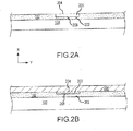
- a painted layer may be at least 0.001 in (0.0254 mm) thick (in the x-direction), i.e. a thickness from a surface of the substrate 100 to a surface line 204 of the painted layer 102.
- an ablated portion 200 of painted layer 102 has been ablated by a laser marking apparatus according to various embodiments.
- Ablated portion 200 has a depth defined between surface line 204 of painted layer 102 and floor 208.
- Floor 208 defines an underlying portion 202 of paint comprised of the painted layer 102.
- contrast layer 206 is applied over painted layer 102, filling the ablated portion 200 above (relative to the x-axis) the floor 208 and underlying portion 202.
- contrast layer 206 is removed leaving a contrasting portion 300 within ablated portion 200 over underlying portion 202 and beneath surface line 204.
- a protective layer 302 such as, for example, a clear coat substantially transmissive to visible light, is applied over the contrasting portion 300 and the painted layer 102.
- a clear coat may comprise one of an enamel, an epoxy, or a resin, such as, for example Testers® spray enamel high gloss, clear, a clear nail polish, AzkoNobel Aerospace Coatings Aerodur® clear overcoat, or WLS Coatings 100-142/CA-1 13 polyurethane coating.
- a protective layer may be between 0.0005 in (0.0127 mm) and 0.002 in (0.0508 mm) thick.
- an article of manufacture 400 having improved visual contrast markings may comprise machine readable information such as a matrix bar code conforming to the ISO/IEC 18004 standard, such as Quick Response (QR) code 402 or printing 404.
- article 400 may further comprise a marking calibration array 406.
- marking calibration array 406 may comprise an array of ablated portions corresponding to a set of configuration settings of a laser part marking apparatus.
- the marking calibration array 406 may correspond to a power output setting of a laser part marking apparatus (e.g., rows 1-4) and a beam dwell time of the laser light (e.g., columns A-U).
- the visual contrast of markings on the painted substrate may tend to be optimized by selecting a particular configuration from the set of configuration settings and thereby configuring the laser part marking apparatus to emit a configured laser light tending to produce markings having optimized visual contrast.
- Method 500 includes applying paint to a substrate to form a painted layer on the substrate (step 502).
- Method 500 includes applying a laser light to a surface of the painted layer to form an ablated portion of the painted layer (step 505), applying a contrast layer over the surface of the painted layer to fill the ablated portion with the contrast layer (step 506), and removing the contrast layer to leave a contrasting portion within the ablated portion (step 508).
- Method 500 may include applying a protective layer over the contrasting portion (step 510).
- Method 600 may include altering the surface of the substrate to improve adhesion of the painted layer (step 602).
- Method 600 may include applying paint to the substrate to form a painted layer over the substrate (step 604).
- Method 600 includes applying a laser light to a surface of the painted layer to form an ablated portion of the painted layer comprising a calibration array (step 606), applying a contrast layer over the surface of the painted layer to fill the ablated portion with the contrast layer (step 608), and removing the contrast layer to leave a contrasting portion within the ablated portion (step 610).
- Method 600 includes configuring a laser marking apparatus based on the calibration array (step 612).
- step 612 further comprises selecting at least one of a beam dwell time, a laser power output, a resolution, a wavelength of laser light, or an ablation depth (step 614).
- references to "various embodiments,” “one embodiment,” “an embodiment,” “an example embodiment,” etc. indicate that the embodiment described may include a particular feature, structure, or characteristic, but every embodiment may not necessarily include the particular feature, structure, or characteristic. Moreover, such phrases are not necessarily referring to the same embodiment. Further, when a particular feature, structure, or characteristic is described in connection with an embodiment, it is submitted that it is within the knowledge of one skilled in the art to affect such feature, structure, or characteristic in connection with other embodiments whether or not explicitly described. After reading the description, it will be apparent to one skilled in the relevant art(s) how to implement the disclosure in alternative embodiments.
Landscapes
- Engineering & Computer Science (AREA)
- Physics & Mathematics (AREA)
- Mechanical Engineering (AREA)
- Optics & Photonics (AREA)
- Plasma & Fusion (AREA)
- Life Sciences & Earth Sciences (AREA)
- Wood Science & Technology (AREA)
- Laser Beam Processing (AREA)
- Thermal Transfer Or Thermal Recording In General (AREA)
Applications Claiming Priority (1)
| Application Number | Priority Date | Filing Date | Title |
|---|---|---|---|
| US15/912,823 US20190275616A1 (en) | 2018-03-06 | 2018-03-06 | Method for improving visual contrast of laser etch marking on painted substrates |
Publications (1)
| Publication Number | Publication Date |
|---|---|
| EP3556566A1 true EP3556566A1 (de) | 2019-10-23 |
Family
ID=65717876
Family Applications (1)
| Application Number | Title | Priority Date | Filing Date |
|---|---|---|---|
| EP19160995.7A Withdrawn EP3556566A1 (de) | 2018-03-06 | 2019-03-06 | Verfahren zur verbesserung der visuellen kontraste von laserätzmarkierungen auf lackierten oberflächen |
Country Status (2)
| Country | Link |
|---|---|
| US (1) | US20190275616A1 (de) |
| EP (1) | EP3556566A1 (de) |
Citations (5)
| Publication number | Priority date | Publication date | Assignee | Title |
|---|---|---|---|---|
| WO1999003688A1 (en) * | 1997-07-16 | 1999-01-28 | Otis Elevator Company | Method and compositions for laser imprinting, and articles imprinted using such methods and compositions |
| WO2006025016A1 (en) * | 2004-09-03 | 2006-03-09 | Koninklijke Philips Electronics N.V. | Method and apparatus for application of a pattern, element and device provided with such a pattern |
| EP2143568A1 (de) * | 2008-07-10 | 2010-01-13 | Demetrio Fiorino | Verfahren für auf einem Verkleidungsplattenelement angebrachte Kaltlasergravuren |
| WO2010083481A2 (en) * | 2009-01-16 | 2010-07-22 | Echelon Laser Systems, Lp | Surface marked articles, related methods and systems |
| EP3061620A1 (de) * | 2015-02-25 | 2016-08-31 | Venair Inc. | Rohrförmiger schlauch mit einer äusseren schicht mit einem code und verfahren zur herstellung davon |
Family Cites Families (8)
| Publication number | Priority date | Publication date | Assignee | Title |
|---|---|---|---|---|
| US6075223A (en) * | 1997-09-08 | 2000-06-13 | Thermark, Llc | High contrast surface marking |
| US8529775B2 (en) * | 2007-02-20 | 2013-09-10 | Revolaze, LLC | Decorative products created by lazing graphics and patterns directly on substrates with painted surfaces |
| DE102007021820A1 (de) * | 2007-05-07 | 2008-11-13 | Chemische Fabrik Budenheim Kg | Laserpigmente für Keramiken |
| WO2010093857A1 (en) * | 2009-02-13 | 2010-08-19 | Videojet Technologies Inc. | Laser parameter adjustment |
| AU2010225226A1 (en) * | 2009-03-18 | 2011-11-10 | Merck Patent Gmbh | Pigment for laser marking |
| DE102010037273A1 (de) * | 2010-09-02 | 2012-03-08 | Schott Ag | Verfahren und Vorrichtung zum Markieren von Glas |
| US8862395B2 (en) * | 2011-01-31 | 2014-10-14 | Raytheon Company | Coded marker navigation system and method |
| US9168760B2 (en) * | 2013-02-01 | 2015-10-27 | Tong Li | Method of creating an image on a stone substrate surface and resulting product |
-
2018
- 2018-03-06 US US15/912,823 patent/US20190275616A1/en not_active Abandoned
-
2019
- 2019-03-06 EP EP19160995.7A patent/EP3556566A1/de not_active Withdrawn
Patent Citations (5)
| Publication number | Priority date | Publication date | Assignee | Title |
|---|---|---|---|---|
| WO1999003688A1 (en) * | 1997-07-16 | 1999-01-28 | Otis Elevator Company | Method and compositions for laser imprinting, and articles imprinted using such methods and compositions |
| WO2006025016A1 (en) * | 2004-09-03 | 2006-03-09 | Koninklijke Philips Electronics N.V. | Method and apparatus for application of a pattern, element and device provided with such a pattern |
| EP2143568A1 (de) * | 2008-07-10 | 2010-01-13 | Demetrio Fiorino | Verfahren für auf einem Verkleidungsplattenelement angebrachte Kaltlasergravuren |
| WO2010083481A2 (en) * | 2009-01-16 | 2010-07-22 | Echelon Laser Systems, Lp | Surface marked articles, related methods and systems |
| EP3061620A1 (de) * | 2015-02-25 | 2016-08-31 | Venair Inc. | Rohrförmiger schlauch mit einer äusseren schicht mit einem code und verfahren zur herstellung davon |
Also Published As
| Publication number | Publication date |
|---|---|
| US20190275616A1 (en) | 2019-09-12 |
Similar Documents
| Publication | Publication Date | Title |
|---|---|---|
| US8377540B2 (en) | Transfer film, method of manufacturing the same, transfer method and object surface structure | |
| CN208962599U (zh) | 附带印刷层的板及使用了该板的显示装置、以及附带功能层的车载显示装置用玻璃 | |
| EP2406085B1 (de) | Klebstoffmarkierungsvorrichtung mit einem trägerfilm und verfahren zur herstellung solch einer vorrichtung | |
| EP2694286B1 (de) | Tafel mit fingerabdruckresistenz und herstellungsverfahren dafür | |
| WO2020078916A2 (en) | Decorative radome and method of producing the same | |
| EP2963458B1 (de) | Linsenrohling mit einer temporären Anti-Rutsch-Beschichtung für ein Verfahren zur Herstellung von Brillengläsern nach Rezept | |
| EP2777944B1 (de) | Fahrzeugfelge mit Druckgraphik und Herstellungsverfahren | |
| HUE033224T2 (hu) | Dekoratív radarantenna-burkolat gépjármû-technikai alkalmazásra | |
| JP2021035764A (ja) | 共硬化性ペイント用フィルムの使用による、複合基板からの下地フィルム及びプライマーの排除 | |
| WO2009014393A1 (en) | Nacre pattern making method using laser | |
| JP6598343B1 (ja) | グラフィックシート、その製造方法及びその使用方法 | |
| US10787753B2 (en) | Anodized substrates with dark laser markings | |
| EP3556566A1 (de) | Verfahren zur verbesserung der visuellen kontraste von laserätzmarkierungen auf lackierten oberflächen | |
| US9272309B2 (en) | Method for applying a pattern, such as a logo, onto the outer skin of an aircraft element | |
| EP2484521A3 (de) | Verfahren zum Aufbringen einer Folie auf einen Träger | |
| JP2011192625A (ja) | キーキャップ構造を製造する方法 | |
| US9919502B2 (en) | Method and apparatus for preparing a surface for bonding a material thereto | |
| US8002932B2 (en) | Method for preparing golf ball with indicia having metallic luster | |
| AU2013278957B2 (en) | Method for applying decorative elements on curved surfaces | |
| JP6157386B2 (ja) | 表面構造体及び当該表面構造体の製造方法 | |
| KR20230174424A (ko) | Uv 코팅을 활용한 카드형 제품 데코레이션 방법 | |
| US20170066011A1 (en) | Methods for applying a coating over laser marking | |
| US10501840B2 (en) | Influence on surface interactions by substructure topography | |
| US6699397B1 (en) | Method of producing transfer stickers with metal powder and transfer stickers produced by the method | |
| CN1230149A (zh) | 带有不同可见颜色区域的金属件 |
Legal Events
| Date | Code | Title | Description |
|---|---|---|---|
| PUAI | Public reference made under article 153(3) epc to a published international application that has entered the european phase |
Free format text: ORIGINAL CODE: 0009012 |
|
| STAA | Information on the status of an ep patent application or granted ep patent |
Free format text: STATUS: THE APPLICATION HAS BEEN PUBLISHED |
|
| AK | Designated contracting states |
Kind code of ref document: A1 Designated state(s): AL AT BE BG CH CY CZ DE DK EE ES FI FR GB GR HR HU IE IS IT LI LT LU LV MC MK MT NL NO PL PT RO RS SE SI SK SM TR |
|
| AX | Request for extension of the european patent |
Extension state: BA ME |
|
| STAA | Information on the status of an ep patent application or granted ep patent |
Free format text: STATUS: REQUEST FOR EXAMINATION WAS MADE |
|
| 17P | Request for examination filed |
Effective date: 20191120 |
|
| RBV | Designated contracting states (corrected) |
Designated state(s): AL AT BE BG CH CY CZ DE DK EE ES FI FR GB GR HR HU IE IS IT LI LT LU LV MC MK MT NL NO PL PT RO RS SE SI SK SM TR |
|
| STAA | Information on the status of an ep patent application or granted ep patent |
Free format text: STATUS: THE APPLICATION IS DEEMED TO BE WITHDRAWN |
|
| 18D | Application deemed to be withdrawn |
Effective date: 20200603 |