EP3556540A1 - Vibration welding device, method for joining at least two elongated components by means of vibration welding and method for the production of said vibration welding device - Google Patents
Vibration welding device, method for joining at least two elongated components by means of vibration welding and method for the production of said vibration welding device Download PDFInfo
- Publication number
- EP3556540A1 EP3556540A1 EP19165435.9A EP19165435A EP3556540A1 EP 3556540 A1 EP3556540 A1 EP 3556540A1 EP 19165435 A EP19165435 A EP 19165435A EP 3556540 A1 EP3556540 A1 EP 3556540A1
- Authority
- EP
- European Patent Office
- Prior art keywords
- oscillating
- units
- heads
- tool
- vibration welding
- Prior art date
- Legal status (The legal status is an assumption and is not a legal conclusion. Google has not performed a legal analysis and makes no representation as to the accuracy of the status listed.)
- Granted
Links
Images


Classifications
-
- B—PERFORMING OPERATIONS; TRANSPORTING
- B29—WORKING OF PLASTICS; WORKING OF SUBSTANCES IN A PLASTIC STATE IN GENERAL
- B29C—SHAPING OR JOINING OF PLASTICS; SHAPING OF MATERIAL IN A PLASTIC STATE, NOT OTHERWISE PROVIDED FOR; AFTER-TREATMENT OF THE SHAPED PRODUCTS, e.g. REPAIRING
- B29C65/00—Joining or sealing of preformed parts, e.g. welding of plastics materials; Apparatus therefor
- B29C65/02—Joining or sealing of preformed parts, e.g. welding of plastics materials; Apparatus therefor by heating, with or without pressure
- B29C65/06—Joining or sealing of preformed parts, e.g. welding of plastics materials; Apparatus therefor by heating, with or without pressure using friction, e.g. spin welding
- B29C65/0609—Joining or sealing of preformed parts, e.g. welding of plastics materials; Apparatus therefor by heating, with or without pressure using friction, e.g. spin welding characterised by the movement of the parts to be joined
- B29C65/0618—Linear
-
- B—PERFORMING OPERATIONS; TRANSPORTING
- B23—MACHINE TOOLS; METAL-WORKING NOT OTHERWISE PROVIDED FOR
- B23K—SOLDERING OR UNSOLDERING; WELDING; CLADDING OR PLATING BY SOLDERING OR WELDING; CUTTING BY APPLYING HEAT LOCALLY, e.g. FLAME CUTTING; WORKING BY LASER BEAM
- B23K1/00—Soldering, e.g. brazing, or unsoldering
- B23K1/06—Soldering, e.g. brazing, or unsoldering making use of vibrations, e.g. supersonic vibrations
-
- B—PERFORMING OPERATIONS; TRANSPORTING
- B23—MACHINE TOOLS; METAL-WORKING NOT OTHERWISE PROVIDED FOR
- B23K—SOLDERING OR UNSOLDERING; WELDING; CLADDING OR PLATING BY SOLDERING OR WELDING; CUTTING BY APPLYING HEAT LOCALLY, e.g. FLAME CUTTING; WORKING BY LASER BEAM
- B23K20/00—Non-electric welding by applying impact or other pressure, with or without the application of heat, e.g. cladding or plating
- B23K20/10—Non-electric welding by applying impact or other pressure, with or without the application of heat, e.g. cladding or plating making use of vibrations, e.g. ultrasonic welding
-
- B—PERFORMING OPERATIONS; TRANSPORTING
- B29—WORKING OF PLASTICS; WORKING OF SUBSTANCES IN A PLASTIC STATE IN GENERAL
- B29C—SHAPING OR JOINING OF PLASTICS; SHAPING OF MATERIAL IN A PLASTIC STATE, NOT OTHERWISE PROVIDED FOR; AFTER-TREATMENT OF THE SHAPED PRODUCTS, e.g. REPAIRING
- B29C65/00—Joining or sealing of preformed parts, e.g. welding of plastics materials; Apparatus therefor
- B29C65/02—Joining or sealing of preformed parts, e.g. welding of plastics materials; Apparatus therefor by heating, with or without pressure
- B29C65/08—Joining or sealing of preformed parts, e.g. welding of plastics materials; Apparatus therefor by heating, with or without pressure using ultrasonic vibrations
-
- B—PERFORMING OPERATIONS; TRANSPORTING
- B29—WORKING OF PLASTICS; WORKING OF SUBSTANCES IN A PLASTIC STATE IN GENERAL
- B29C—SHAPING OR JOINING OF PLASTICS; SHAPING OF MATERIAL IN A PLASTIC STATE, NOT OTHERWISE PROVIDED FOR; AFTER-TREATMENT OF THE SHAPED PRODUCTS, e.g. REPAIRING
- B29C66/00—General aspects of processes or apparatus for joining preformed parts
- B29C66/50—General aspects of joining tubular articles; General aspects of joining long products, i.e. bars or profiled elements; General aspects of joining single elements to tubular articles, hollow articles or bars; General aspects of joining several hollow-preforms to form hollow or tubular articles
-
- B—PERFORMING OPERATIONS; TRANSPORTING
- B29—WORKING OF PLASTICS; WORKING OF SUBSTANCES IN A PLASTIC STATE IN GENERAL
- B29C—SHAPING OR JOINING OF PLASTICS; SHAPING OF MATERIAL IN A PLASTIC STATE, NOT OTHERWISE PROVIDED FOR; AFTER-TREATMENT OF THE SHAPED PRODUCTS, e.g. REPAIRING
- B29C66/00—General aspects of processes or apparatus for joining preformed parts
- B29C66/80—General aspects of machine operations or constructions and parts thereof
- B29C66/83—General aspects of machine operations or constructions and parts thereof characterised by the movement of the joining or pressing tools
- B29C66/832—Reciprocating joining or pressing tools
- B29C66/8322—Joining or pressing tools reciprocating along one axis
-
- B—PERFORMING OPERATIONS; TRANSPORTING
- B29—WORKING OF PLASTICS; WORKING OF SUBSTANCES IN A PLASTIC STATE IN GENERAL
- B29C—SHAPING OR JOINING OF PLASTICS; SHAPING OF MATERIAL IN A PLASTIC STATE, NOT OTHERWISE PROVIDED FOR; AFTER-TREATMENT OF THE SHAPED PRODUCTS, e.g. REPAIRING
- B29C66/00—General aspects of processes or apparatus for joining preformed parts
- B29C66/90—Measuring or controlling the joining process
- B29C66/95—Measuring or controlling the joining process by measuring or controlling specific variables not covered by groups B29C66/91 - B29C66/94
- B29C66/951—Measuring or controlling the joining process by measuring or controlling specific variables not covered by groups B29C66/91 - B29C66/94 by measuring or controlling the vibration frequency and/or the vibration amplitude of vibrating joining tools, e.g. of ultrasonic welding tools
- B29C66/9513—Measuring or controlling the joining process by measuring or controlling specific variables not covered by groups B29C66/91 - B29C66/94 by measuring or controlling the vibration frequency and/or the vibration amplitude of vibrating joining tools, e.g. of ultrasonic welding tools characterised by specific vibration frequency values or ranges
-
- B—PERFORMING OPERATIONS; TRANSPORTING
- B29—WORKING OF PLASTICS; WORKING OF SUBSTANCES IN A PLASTIC STATE IN GENERAL
- B29L—INDEXING SCHEME ASSOCIATED WITH SUBCLASS B29C, RELATING TO PARTICULAR ARTICLES
- B29L2031/00—Other particular articles
- B29L2031/30—Vehicles, e.g. ships or aircraft, or body parts thereof
- B29L2031/3005—Body finishings
- B29L2031/3008—Instrument panels
-
- B—PERFORMING OPERATIONS; TRANSPORTING
- B29—WORKING OF PLASTICS; WORKING OF SUBSTANCES IN A PLASTIC STATE IN GENERAL
- B29L—INDEXING SCHEME ASSOCIATED WITH SUBCLASS B29C, RELATING TO PARTICULAR ARTICLES
- B29L2031/00—Other particular articles
- B29L2031/30—Vehicles, e.g. ships or aircraft, or body parts thereof
- B29L2031/3044—Bumpers
-
- B—PERFORMING OPERATIONS; TRANSPORTING
- B29—WORKING OF PLASTICS; WORKING OF SUBSTANCES IN A PLASTIC STATE IN GENERAL
- B29L—INDEXING SCHEME ASSOCIATED WITH SUBCLASS B29C, RELATING TO PARTICULAR ARTICLES
- B29L2031/00—Other particular articles
- B29L2031/747—Lightning equipment
Definitions
- the present invention relates to a vibration welding apparatus with a mechanically coupled multiple oscillator.
- the present invention relates to the use of a vibration welding device for welding at least two elongate components, a method for joining at least two elongate components by means of said vibration welding device, and a manufacturing method for the vibration welding device, in which a plurality of electromechanical oscillators are mechanically coupled.
- vibration welding is a well-known process.
- two plastic parts are connected by means of friction and thereby generated heat.
- a plastic part is held and the other moved under pressure linear or orbital against the other plastic part.
- the relative movement of the plastic parts relative to one another takes place along the longer side of the geometry of the vibrating component.
- the components are placed in the machine via a tool in such a way that a welding surface that is as level as possible is created in the direction of movement.
- the weld seam design is structurally selected such that the welding direction takes place in the direction of the longest side of the component.
- the component has large bevels or, for example, a right-angled course change, e.g. L-shaped, is present, a swinging in the longitudinal direction is not possible. This is e.g. in the automotive industry for bumpers, corner taillights and also on dashboards of the case.
- a standard welding machine with oscillation direction in the Y direction is used to weld an elongate component with longitudinal extension in the Y direction.
- the component is rotated by 90 °, so that the shorter X-axis of the component is now oriented in the Y-direction of oscillation of the welding machine. Equivalent to this would also be a turning of the oscillating head by 90 ° and maintaining the orientation of the component. In this case, the component hangs over much laterally and the associated mass distribution leads to an asymmetric swinging (or staggering) of the component. Accordingly, the weld / connection is defective. Also, the ergonomics for loading and unloading the machine is unfavorable and error prone.
- two oscillating heads arranged next to one another form too small a width for the elongate component, so that plastic parts which have a large length in the Y direction are not optimally adapted to the oscillators.
- the components interfere unfavorably in the Y direction via the oscillating heads and negatively influence the oscillation behavior (tend to wobble).
- two vibrating heads that are far apart in the Y direction are difficult to control, which has a negative effect on the desired vibration behavior in the X direction.
- oscillating heads are electronically coupled.
- This arrangement is in EP 1 772 253 B1 "Apparatus and method for vibration welding" described.
- the slaves are controlled to the amplitude and phase of the master so that all oscillating units oscillate in phase and amplitude synchronous.
- each oscillating head is considered as a single unit and the maximum number of oscillating heads possible is limited only by the speed of control.
- each oscillating head assembly has a separate tool.
- a disadvantage is that all tools in weight and geometry must be almost identical in order to achieve equal frequencies of the oscillating heads. Namely, the vibration vibrating heads are always operated at or near the resonance frequency which is weight-dependent. This frequency must be the same or at least so close to each oscillating heads that a common control with a common frequency is possible.
- a deviation of the control of a single oscillating head by only 0.1 Hz leads at a vibration frequency of 100 Hz after only 5 seconds to a phase reversal of the individual oscillating head.
- a plurality of known vibration units from the technical field of vibration welding in this case at least three vibration units, are approximately perpendicular with their vibration direction are arranged to a longitudinal direction of oblong components to be welded together. Due to their arrangement, the plurality of oscillating units generate a relative transverse vibration of the components to be interconnected with respect to their longitudinal axis.
- the oscillating units can preferably be matched to one another in terms of their oscillation properties, such as amplitude and frequency. Accordingly, these several mechanically coupled, preferably double mechanically coupled, oscillating units or oscillating heads (see below) form the mechanically coupled multiple oscillator.
- This construction ensures that uniform transversal oscillations of the at least three oscillating units or oscillating heads are transmitted via the tool to the components to be connected to one another such that they are reliably connected to one another despite the non-longitudinal vibration vibrations.
- the use of at least three oscillating units allows a sufficient extent of the components to be joined together in their longitudinal direction, so that, for example, a staggering of the moving component is sufficiently reduced.
- At least three oscillating units are spring-mounted on a common bridge.
- the at least three oscillating units or vibrating heads are fixed evenly distributed over the longitudinal direction of the tool on the common bridge or a component connecting the oscillating heads. Because of this uniformly distributed arrangement, the oscillations are transmitted approximately transversely to the longitudinal axis of the tool over the tool evenly over approximately the entire longitudinal extension of the component which can be connected to the tool.
- a known vibration unit for vibration vibration consists of the above-mentioned at least one pair of oppositely arranged electromagnetic coils and a spring-supported oscillator arranged therebetween.
- the oscillator is held by a spring assembly on a bridge which preferably spans the electromagnetic coils.
- an upper tool is fastened to the oscillator directly or via a coupling element.
- This common bridge which is otherwise provided individually in each oscillating unit, forms a simultaneous basis for all oscillating units and spring assemblies attached thereto.
- the base benefits from the cumulative mass of the individual bridges to a total vibration mass, which would otherwise be provided in each individual vibration unit.
- the oscillating units or oscillating heads are preferably uniformly laterally spaced from one another in coordination with the longitudinal extent of the tool. This arrangement ensures that the mechanically coupled vibrating units or vibrating heads transmit the transverse vibrations throughout the entire length of the tool to assist smooth swinging and reduce staggering of the component.
- one of the plurality of oscillation units forms a master oscillation unit, while the remaining oscillation units each form a slave oscillation unit with respect to the master oscillation unit, so that all oscillation units are synchronously operable.
- a master-slave circuit is used. Accordingly, the master-slave circuit forms an additional assurance stage for a coordinated operation of the plurality of oscillating units and / or oscillating heads.
- the vibration welding device according to another embodiment, at least three oscillating heads, which form the mechanically coupled multiple oscillator.
- These oscillating heads each comprise at least one pair of oppositely arranged electromagnetic coils with a vibrator arranged between these coils.
- the oscillator is attached to a bridge via a spring assembly.
- This preferred embodiment is further characterized in that the bridges of the plurality of oscillating heads are mechanically connected to each other and that the oscillating heads are also connected to each other via the elongated tool.
- At least three oscillating heads are mechanically coupled to preferably two sides.
- the one coupling side forms the mechanical connection of the individual bridges of these oscillating heads.
- the other coupling side is formed by a tool connecting the oscillating heads or a coupling element arranged between the tool and oscillating head.
- N vibrating heads By coupling the bridges together and / or by coupling the vibrator units together, whether by a common base plate to which the tool is screwed, or by the tool itself, N vibrating heads create a physical unit acting as a vibrating head. This results in only one resonance frequency and one oscillation direction. It then no longer matters whether the weight of the tool is evenly distributed to the N vibrating plates or not, since now the total mass of the vibrating units forms the new oscillating mass. Accordingly, this mechanical connection of the plurality of oscillating heads ensures that the plurality of oscillating heads oscillate in phase synchronization and, moreover, with the same amplitude.
- the plurality of oscillating units or the plurality of oscillating heads form a mechanical unit having approximately a rectangular contour with an aspect ratio of A / B ⁇ 1.0, one forming a lower limit.
- a and B describe the side lengths of the overall unit, which are significant to the mass of the overall unit. It is understood that merely the device clad housing parts do not contribute significantly to the mass of the overall unit. Rather, coupled bridges, base plates, tools, vibrating units and the like contribute significantly to the overall mass.
- the side A runs approximately parallel to the first direction of the vibrations of the oscillating units or oscillating heads and the side B extends approximately parallel to a longitudinal axis of the tool.
- a size and arrangement of the entire unit according to the above dimensions mechanically supports the vibration behavior of the plurality of interconnected vibration units or oscillating heads.
- it causes the mechanically interconnected multiple oscillating units or oscillating heads to act as a single oscillating head.
- just the size of the aspect ratio of the entire unit of importance The larger the aspect ratio, the more pronounced is the tendency of the overall system to oscillate in the first direction, ie parallel to side A.
- the influence associated with the construction of the overall unit preferably provides for harmonic oscillation of the interconnected vibrating units or vibrating heads of equal frequency, phase and amplitude.
- the approximately rectangular contour of the connected vibration units or oscillating heads having the common vibration mass has an aspect ratio of A / B ⁇ 2.0.
- the tool for receiving the component has a length of at least 1 m, preferably a length of ⁇ 2 m.
- the tool length emphasizes that it is precisely the combination of several transversely oscillating and mechanically coupled oscillating units or oscillating heads with an elongated tool that supports stable vibration welding in the transverse direction to the tool or component length.
- the present invention also includes the use of a vibration welding apparatus according to any of the above-described embodiments for welding at least two elongate members having a long side to a short side aspect ratio greater than one, the welding vibrations being approximately parallel to the shorter side of the components to be joined are aligned.
- the present invention discloses a method for joining at least two elongated components by means of vibration welding, in particular with a vibration welding device according to one of the embodiments described above.
- the vibration welding method according to the invention comprises the following steps: clamping an elongate component in a tool, which is mechanically connected to at least three oscillating units mechanically coupled to each other or at least three vibrating heads of a vibration welding device mechanically coupled to each other, generating vibrations of the component via the tool connected to the oscillating units or the oscillating heads such that a first direction of the vibrations is unequal to a longitudinal axis of the component, preferably aligned transversely to the longitudinal axis of the component, and connecting the at least two components by the first oscillating member and the second component are pressed against each other.
- an arrangement acting as a swinging head results, which covers a sufficient longitudinal section of the elongated component, in order to transmit via these transverse vibrations for connection to a further component.
- the oscillating units or the oscillating heads are preferably mechanically coupled to one another twice, namely on the tool side and on the bridge side.
- the vibration-generating coils are preferably energized together by a power supply unit and the coupled vibration units act as a single vibration unit.
- the vibration welding method has the additional steps: driving at least one oscillating unit as a master oscillating unit or driving at least one oscillating head as a master oscillating head and driving the remaining oscillating units respectively as a slave oscillating unit or the remaining vibrating heads as slave oscillators Oscillating head with respect to the master oscillating unit or the master oscillating head.
- electronic coupling is preferred (see above).
- the electronic coupling via a master-slave control preferably forms an additional support for a synchronized operation of the plurality of vibration units and / or oscillating heads.
- the present invention also includes a manufacturing method for a vibration welding apparatus, comprising the steps of providing at least three oscillating units or oscillating heads each consisting of at least one pair of opposed electromagnetic coils with a spring-supported vibrator interposed therebetween, connecting the at least three oscillating units or vibrating heads via an elongated one A tool with which a component to be welded is movable, wherein the elongate tool is arranged with respect to the at least three oscillating units such that a first direction of the oscillations of the oscillating units or of the oscillating heads is aligned unequal to a longitudinal axis of the elongated tool.
- the manufacturing method comprises the further step of connecting the oscillating units or oscillating heads to a total mechanical unit defining an approximately rectangular contour with an aspect ratio of preferably A / B ⁇ 1.0 in which A is parallel to one first direction of the vibrations of the oscillating units or oscillating heads and B are arranged parallel to a longitudinal axis of the tool.
- FIG. 1 shows a known oscillating head 2 with a preferred oscillating unit 20.
- the oscillating unit 20 includes a pair of oppositely disposed electromagnetic coils 22. At this point, the use of multiple pairs of oppositely disposed electromagnetic coils 22 is also preferred.
- the coils 22 When energized alternately, the coils 22 set a vibrator 24 arranged between them into a linear oscillation. To support the vibration of the vibrator 24, this is fastened via a spring assembly 26 to a bridge 28.
- the vibrator 24 is connected to a tool 30.
- the tool 30 is used to receive a component to the vibrations of the Schwingers 24 to transfer the component. If the oscillating component is pressed against another component, the frictional heat generated by the vibrations leads to the connection of the two components.
- the arrangement of the coils 22 oscillates the oscillator 24 and thus also the tool 30 in the longitudinal direction of the vibrator 24 (see double arrow in FIG. 1 ).
- components B1, B2 are vibrated in the longitudinal direction, that is, in the Y direction, to be connected by vibration welding. This would in the preferred L and U-shaped components B1, B2 of the FIGS. 2A and 2B lead to damage of the components.
- the components B1, B2 are preferably vibrated in the X direction, ie preferably transversely to the longitudinal axis of the components B1, B2.
- a U-shaped or L-shaped elongated component B1, B2 extending in the Y direction it is set into vibration transversely to its longitudinal direction, that is to say in the X direction.
- at least three oscillating units 20 or at least three oscillating heads 2 are mechanically coupled to one another in order to oscillate approximately uniformly.
- Oscillating unit 20 refers in this context, the combination of coil 22, vibrator 24, spring assembly 26 and bridge 28th
- the at least three oscillation units 20 are arranged with their oscillation direction parallel to the X direction and thus transversely to the longitudinal axis of the components B1, B2.
- the vibration units 20 are arranged parallel to each other, as can be seen in FIG. 3 can recognize.
- the at least three oscillating units 20 are distributed uniformly in the longitudinal direction of the components B1, B2 in order to transmit the oscillation as uniformly as possible over the entire component length or a larger part of the component length. Therefore, it is also preferable to use more than three vibrating units 20 in a parallel arrangement, for example, four, five or six vibrating units 20 or vibrating heads 2.
- the oscillating units 20 are all preferably connected directly or indirectly via a common coupling element 40 to the same tool 30. This supports the preferred operation of the plurality of oscillating units 20 at approximately the same frequency and amplitude. In this way, reliable welding results are achieved.
- the vibration welding device acts like a single oscillating head.
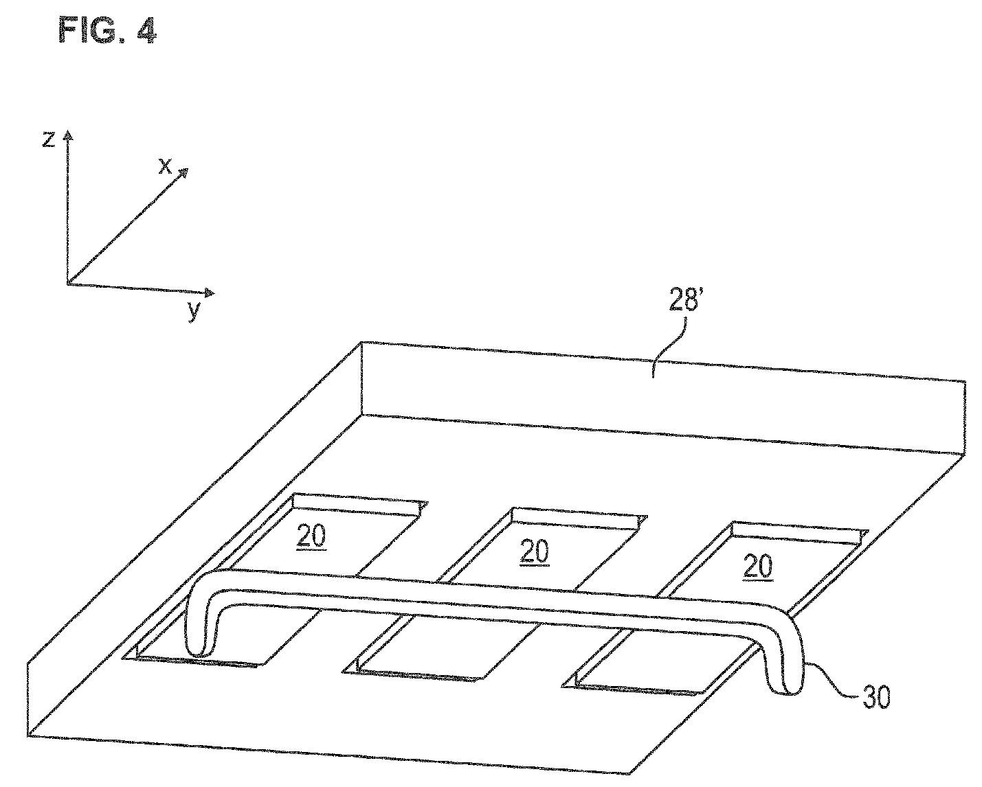
- the joint operation of the at least three oscillating units 20 is additionally improved in that the oscillating units 20 are attached to a common bridge 28 '. Accordingly, the common bridge 28 'supports and holds the plurality of spring assemblies 26, the coil pairs 22, and the vibrator 24 of the plurality of oscillating units 20. This is schematically illustrated in FIG FIG. 4 illustrated. As a result, the at least three oscillating units 20 are mechanically coupled to one another twice, namely via the preferably continuously extending tool 30 and the common bridge 28 '.
- the coupling element 40 is not shown. Nevertheless, it is preferable to use the coupling element 40 for connecting the vibration unit 20 and the tool 30.
- FIGS. 6 and 7 show a further preferred embodiment of the present invention.
- the mechanical coupling takes place via the continuous tool 30.
- the tool 30 is connected to each setting head 2 via a preferred coupling element 40 (not shown).
- FIG. 6 contains each oscillating head 2 as a subcomponent, a vibration unit 20, as in the prior art FIG. 1 is known.
- connecting element 50 thus fulfills the same function as the common bridge 28 'described above.
- the length of the side A In order to mechanically support a vibration behavior in the X direction, it is preferable to set the length of the side A greater than or at least equal to the length of the side B of the overall unit 60.
- the aspect ratio A / B of the entire unit 60 is in a preferable range of A / B ⁇ 1.0.
- the aspect ratio A / B of the overall unit 60 is in a preferred range of A / B ⁇ 2 , 0th
- the coupled oscillating units or vibrating heads (see below) with a tool of at least 1 m in length, preferably a length of ⁇ 2 m.
- the tool length ensures that the transverse vibrations of the combination of the plurality of transversely oscillating and mechanically coupled oscillating units or oscillating heads can be transmitted uniformly over the entire length of the component.
- one of the several oscillating units 20 or one of the several oscillating heads 2 is operated as a master, as shown in FIG EP 1 772 253 B1 is described. Accordingly, the at least two other oscillation units or oscillation heads 2 are driven as a slave.
- EP 1 772 253 B1 referred to, which is hereby incorporated by reference.
- an inharmonic oscillation is additionally preferably harmonized, which preferably prevents staggering of the tool or of the components to be connected to one another.
- the above-described preferred embodiments of the vibration welding apparatus are preferably used for the vibration welding of elongate members. These are preferably lights, bumpers, dashboards or applications other than the automotive sector. These elongate components are characterized by an aspect ratio of the long component side to the short component side over one. As described above, the vibrations for vibration welding these components are parallel to the short side of the elongate members.
- connection method according to the invention for at least two elongate components by means of vibration welding will be described with reference to the flowchart in FIG FIG. 9 summarized.
- a first step S1 the elongated component B1 is clamped in the tool 30.
- the tool is mechanically connected to at least three oscillating units 20 or at least three vibrating heads 2 of the vibration welding apparatus.
- step S2 the components to be joined together are set in relative oscillations via the tool 3 connected to the oscillating units 20 or to the oscillating heads 2. These relative vibrations are oriented unequal to the longitudinal axis of the component, preferably transversely to the longitudinal axis of the components.
- step S3 at least one oscillation unit or at least one oscillation head 2 is actuated as a master oscillation unit or as a master oscillation head.
- the remaining oscillation units 20 are driven as slave oscillation units or the remaining oscillation heads 2 are driven as slave oscillation heads with respect to the master oscillation unit or the master oscillation head.
- step S5 the at least two components are then connected, in which the first oscillating component is brought into contact with the second component B2.
- the present invention includes a manufacturing method for a vibration welding apparatus, which is described with reference to the flowchart in FIG. 10 is described.
- This production method comprises the following steps: first, in step H1, provision is made of at least three oscillation units 20 or oscillating heads 2 with the structural design already described above. Subsequently, in step H2, the at least three oscillating units 20 or the oscillating heads 2 are then connected to one another via the elongate tool 30. In this case, the tool 30 is connected to the oscillating units 20 or the oscillating heads 2 in such a way that a first direction of the oscillations of the oscillating units 20 or of the oscillating heads 2 is aligned unequal to a longitudinal axis of the elongated tool 30.
- the at least three oscillating units 20 or oscillating heads 2 are fastened in parallel arrangement on a common bridge 28 'or the connecting element 50 described above. Due to the preferred mechanical couplings of the at least three oscillating units 20 or the at least three vibrating heads 2 via the tool 30 and the common bridge 28 'or the connecting element 50 results in a mechanical total unit 60 of the vibration welding device.
- This mechanical total unit 60 preferably has an approximately rectangular contour with an aspect ratio of preferably A / B ⁇ 1.0, and more preferably A / B ⁇ 2.
- the side surfaces A, B of the overall unit 60 are oriented as described above.
Landscapes
- Engineering & Computer Science (AREA)
- Mechanical Engineering (AREA)
- Lining Or Joining Of Plastics Or The Like (AREA)
- Pressure Welding/Diffusion-Bonding (AREA)
Abstract
Vorliegende Erfindung beschreibt eine Vibrationsschweißvorrichtung mit einem mechanisch gekoppelten Mehrfachschwinger. Innerhalb dieser Vibrationsschweißvorrichtung sind die mehreren Schwingeinheiten (20) in Bezug auf ein längliches Werkzeug (30) derart angeordnet, dass die erste Richtung der Schwingungen der einzelnen Schwingeinheiten (20) annähernd quer zu einer Längsachse des Werkzeugs (30) ausgerichtet ist, sodass während eines Vibrationsschweißvorgangs zwei Bauteile durch Schwingungen ungleich einer Längsrichtung der Bauteile miteinander verschweißbar sind.
Description
Die vorliegende Erfindung betrifft eine Vibrationsschweißvorrichtung mit einem mechanisch gekoppelten Mehrfachschwinger. Zudem betrifft vorliegende Erfindung die Verwendung einer Vibrationsschweißvorrichtung zum Verschweißen von mindestens zwei länglichen Bauteilen, ein Verfahren zum Verbinden von mindestens zwei länglichen Bauteilen mithilfe der genannten Vibrationsschweißvorrichtung sowie ein Herstellungsverfahren für die Vibrationsschweißvorrichtung, in der mehrere elektromechanische Schwinger mechanisch gekoppelt werden.The present invention relates to a vibration welding apparatus with a mechanically coupled multiple oscillator. In addition, the present invention relates to the use of a vibration welding device for welding at least two elongate components, a method for joining at least two elongate components by means of said vibration welding device, and a manufacturing method for the vibration welding device, in which a plurality of electromechanical oscillators are mechanically coupled.
In der Kunststoffverbindungstechnik ist das Vibrationsschweißen ein bekanntes Verfahren. Hierbei werden zwei Kunststoffteile mittels Reibung und dabei erzeugter Wärme verbunden. Im Allgemeinen wird ein Kunststoffteil festgehalten und das andere unter Druck linear bzw. orbital gegen das andere Kunststoffteil bewegt.In plastic joining technology, vibration welding is a well-known process. Here, two plastic parts are connected by means of friction and thereby generated heat. In general, a plastic part is held and the other moved under pressure linear or orbital against the other plastic part.
Beim linearen Vibrationsschweißen erfolgt die relative Bewegung der Kunststoffteile gegeneinander entlang der längeren Seite der Geometrie des schwingenden Bauteils. Um das Bewegen gegen Schrägen zu verhindern werden die Bauteile über ein Werkzeug dergestalt in die Maschine gelegt, dass in Bewegungsrichtung eine möglichst ebene Schweißfläche entsteht.In linear vibration welding, the relative movement of the plastic parts relative to one another takes place along the longer side of the geometry of the vibrating component. In order to prevent movement against slants, the components are placed in the machine via a tool in such a way that a welding surface that is as level as possible is created in the direction of movement.
Bei länglichen Teilen wird konstruktiv die Schweißnahtgestaltung so gewählt, dass die Schweißrichtung in Richtung der längsten Seite des Bauteiles erfolgt.In the case of elongated parts, the weld seam design is structurally selected such that the welding direction takes place in the direction of the longest side of the component.
Wenn nun in der Längsrichtung das Bauteil große Schrägen aufweist oder bspw. eine rechtwinklige Verlaufsänderung, z.B. L-förmig, vorhanden ist, ist ein Schwingen in Längsrichtung nicht möglich. Dies ist z.B. in der Automobilindustrie bei Stoßfängern, um die Ecke gehenden Rückleuchten und auch bei Armaturentafeln der Fall.If, in the longitudinal direction, the component has large bevels or, for example, a right-angled course change, e.g. L-shaped, is present, a swinging in the longitudinal direction is not possible. This is e.g. in the automotive industry for bumpers, corner taillights and also on dashboards of the case.
Aktuell geht der Trend zu durchgehenden, um die Ecke reichenden Rückleuchten. Dies sind Bauteile, die bei einer Tiefe in X-Richtung von typisch weniger als 20 cm eine Länge in Y-Richtung von fast 2 m oder mehr erreichen und U-förmig sind.Currently, the trend is towards continuous, around the corner reaching taillights. These are components that reach a length in the Y direction of almost 2 m or more and are U-shaped at a depth in the X direction of typically less than 20 cm.
Aktuell werden diese Anwendungen folgendermaßen geschweißt:
Gemäß einer ersten Alternative wird eine Standard-Schweißmaschine mit Schwingrichtung in Y-Richtung genutzt, um ein längliches Bauteil mit Längserstreckung in Y-Richtung zu verschweißen. Das Bauteil wird um 90° gedreht, so dass die kürzere X-Achse des Bauteils nun in Y-Schwingungsrichtung der Schweißmaschine orientiert ist. Äquivalent dazu wäre auch ein Drehen des Schwingkopfes um 90° und Beibehaltung der Ausrichtung des Bauteils. In diesem Falle hängt das Bauteil weit seitlich über und die damit verbundene Massenverteilung führt zu einem asymmetrischen Schwingen (oder Torkeln) des Bauteils. Entsprechend ist die Schweißnaht/-verbindung mangelhaft. Auch ist die Ergonomie zum Be- und Entladen der Maschine ungünstig und fehlerträchtig.Currently these applications are welded as follows:
According to a first alternative, a standard welding machine with oscillation direction in the Y direction is used to weld an elongate component with longitudinal extension in the Y direction. The component is rotated by 90 °, so that the shorter X-axis of the component is now oriented in the Y-direction of oscillation of the welding machine. Equivalent to this would also be a turning of the oscillating head by 90 ° and maintaining the orientation of the component. In this case, the component hangs over much laterally and the associated mass distribution leads to an asymmetric swinging (or staggering) of the component. Accordingly, the weld / connection is defective. Also, the ergonomics for loading and unloading the machine is unfavorable and error prone.
In einer zweiten Alternative werden zwei Schwingköpfe in gleicher Orientierung wie in der ersten Alternative genutzt. Diese Anordnung hat den Nachteil, dass die beiden Schwingköpfe nur mit großem Regelungsaufwand phasensynchron schwingen. Ein weiterer Nachteil ergibt sich aufgrund der Unterschiede in den Schwingungsamplituden der verwendeten Schwingköpfe. Unterschiedliche Amplituden resultieren in ungleichmäßige Schweißergebnisse. Auch setzt dieser Umstand eine gewisse Flexibilität des zu verschweißenden Bauteils oder der Bauteilaufnahme (Oberwerkzeug) voraus, was sich ebenfalls negativ auf die Schweißergebnis auswirkt.In a second alternative, two oscillating heads are used in the same orientation as in the first alternative. This arrangement has the disadvantage that the two oscillating heads vibrate phase-synchronously only with great control effort. Another disadvantage arises due to the differences in the vibration amplitudes of the oscillating heads used. Different amplitudes result in uneven welding results. Also, this circumstance requires a certain flexibility of the component to be welded or the component holder (upper tool), which also has a negative effect on the welding result.
Zudem bilden zwei nebeneinander angeordnete Schwingköpfe eine zu geringe Baubreite für das längliche Bauteil ab, so dass Kunststoffteile, welche eine große Länge in Y-Richtung besitzen, nicht optimal an die Schwinger angepasst sind. Die Bauteile stehen ungünstig in Y-Richtung über die Schwingköpfe über und beeinflussen das Schwingverhalten negativ (neigen zum Torkeln). Andererseits sind zwei in Y-Richtung weit auseinander liegende Schwingköpfe schwer zu regeln, was sich auf das gewünschte Schwingverhalten in X-Richtung negativ auswirkt.In addition, two oscillating heads arranged next to one another form too small a width for the elongate component, so that plastic parts which have a large length in the Y direction are not optimally adapted to the oscillators. The components interfere unfavorably in the Y direction via the oscillating heads and negatively influence the oscillation behavior (tend to wobble). On the other hand, two vibrating heads that are far apart in the Y direction are difficult to control, which has a negative effect on the desired vibration behavior in the X direction.
In einer dritten Alternative werden mehrere Schwingköpfe elektronisch gekoppelt. Diese Anordnung ist in
Der Vorteil dieses Verfahrens ist, dass jeder Schwingkopf als einzelne Einheit betrachtet wird und die maximale Anzahl der möglichen Schwingköpfe nur durch die Schnelligkeit der Regelung begrenzt wird. Bei dieser Anordnung individueller Schwingköpfe weist jede Schwingkopfanordnung ein getrenntes Werkzeug auf. Nachteilig ist dabei, dass alle Werkzeuge in Gewicht und Geometrie nahezu identisch sein müssen, um gleiche Frequenzen der Schwingköpfe zu erreichen. Die Vibrationsschwingköpfe werden nämlich immer in oder nahe der Resonanzfrequenz betrieben, welche gewichtsabhängig ist. Diese Frequenz muss bei allen Schwingköpfen gleich oder doch zumindest so nah beieinander sein, dass eine gemeinsame Regelung mit einer gemeinsamen Frequenz möglich ist. Eine Abweichung der Regelung eines einzelnen Schwingkopfes um nur 0,1 Hz führt jedoch bei einer Schwingfrequenz von 100 Hz nach nur 5 Sekunden zu einer Phasenumkehr des einzelnen Schwingkopfes. Selbst bei optimaler Regelung oder Steuerung der Frequenz kommt es während des An- und Ausschwingens noch zu kleinen Abweichungen in der Amplitude. Für die individuellen Schwingköpfe bzw. das Gesamtsystem ist das erstmal kein Problem. Dies verlangt jedoch eine gewisse Flexibilität im Kunststoffbauteil, welches diese Abweichungen letztlich aufnehmen muss, was wiederum zu einem schlechteren Schweißergebnis führt.The advantage of this method is that each oscillating head is considered as a single unit and the maximum number of oscillating heads possible is limited only by the speed of control. In this arrangement of individual oscillating heads, each oscillating head assembly has a separate tool. A disadvantage is that all tools in weight and geometry must be almost identical in order to achieve equal frequencies of the oscillating heads. Namely, the vibration vibrating heads are always operated at or near the resonance frequency which is weight-dependent. This frequency must be the same or at least so close to each oscillating heads that a common control with a common frequency is possible. However, a deviation of the control of a single oscillating head by only 0.1 Hz leads at a vibration frequency of 100 Hz after only 5 seconds to a phase reversal of the individual oscillating head. Even with optimal regulation or control of the frequency, there are still small deviations in the amplitude during the on and off swinging. For the individual oscillating heads or the entire system, this is no problem at first. However, this requires a certain flexibility in the plastic component, which must ultimately absorb these deviations, which in turn leads to a poorer welding result.
Es stellt sich somit die technische Aufgabe, eine alternative Konstruktion einer Vibrationsschweißvorrichtung bereitzustellen, mit der gerade langgestreckte U-förmige oder L-förmige Bauteile mittels Vibrationsschweißen verbindbar sind.It is therefore the technical task to provide an alternative construction of a vibration welding device, with the straight elongated U-shaped or L-shaped components are connected by means of vibration welding.
Die obige Aufgabe wird durch eine Vibrationsschweißvorrichtung gemäß dem unabhängigen Patentanspruch 1, die Verwendung einer Vibrationsschweißvorrichtung gemäß dem unabhängigen Patentanspruch 6, ein Verfahren zum Verbinden von mindestens zwei länglichen Bauteilen mittels einer Vibrationsschweißvorrichtung gemäß dem unabhängigen Patentanspruch 7 sowie durch ein Herstellungsverfahren für eine Vibrationsschweißvorrichtung gemäß dem unabhängigen Patentanspruch 9 gelöst. Vorteilhafte Ausgestaltungen und Weiterentwicklungen vorliegender Erfindung gehen aus der folgenden Beschreibung, den begleitenden Zeichnungen und den anhängenden Patentansprüchen hervor.The above object is achieved by a vibration welding apparatus according to
Die erfindungsgemäße Vibrationsschweißvorrichtung mit einem mechanisch gekoppelten Mehrfachschwinger weist die folgenden Merkmale auf: mindestens drei Schwingeinheiten jeweils bestehend aus mindestens einem Paar einander gegenüberliegender elektromagnetischer Spulen, mit denen ein dazwischen angeordneter federunterstützter Schwinger in lineare Schwingungen in einer ersten Richtung versetzbar ist, ein längliches Werkzeug, mit dem ein zu verschweißendes Bauteil bewegbar ist und welches mit allen Schwingeinheiten mechanisch verbunden ist, wobei die Schwingeinheiten in Bezug auf das längliche Werkzeug derart angeordnet sind, dass die erste Richtung der Schwingungen der einzelnen Schwingeinheiten annähernd quer zu einer Längsachse des Werkzeugs ausgerichtet ist, sodass während eines Vibrationsschweißvorgangs zwei Bauteile durch Schwingungen ungleich einer Längsrichtung der Bauteile, insbesondere quer zu einer Längsrichtung, miteinander verschweißbar sind.The vibration welding device according to the invention with a mechanically coupled multiple oscillator has the following features: at least three oscillating units each consisting of at least one pair of opposed electromagnetic coils, with which a spring-assisted oscillator arranged therebetween can be set into linear oscillations in a first direction, an elongate tool with which a component to be welded is movable and which is mechanically connected to all the oscillating units, wherein the oscillating units in With respect to the elongated tool are arranged such that the first direction of the vibrations of the individual oscillating units is aligned approximately transversely to a longitudinal axis of the tool, so that during a vibration welding operation, two components by vibration unequal to a longitudinal direction of the components, in particular transversely to a longitudinal direction, welded together are.
Beim Vibrationsschweißen von lang gestreckten Bauteilen, die vorzugsweise eine U-Form oder eine L-Form aufweisen, hat es sich als vorteilhaft erwiesen, wenn eine Mehrzahl von bekannten Schwingeinheiten aus dem technischen Gebiet des Vibrationsschweißens, hier mindestens drei Schwingeinheiten, mit ihrer Schwingungsrichtung annähernd senkrecht zu einer Längsrichtung von miteinander zu verschweißenden länglichen Bauteilen angeordnet werden. Aufgrund ihrer Anordnung erzeugen die mehreren Schwingeinheiten eine relative Querschwingung der miteinander zu verbindenden Bauteile in Bezug auf deren Längsachse. Da die mindestens drei Schwingeinheiten durch ein gemeinsames Werkzeug oder ein entsprechendes Kopplungselement zwischen Werkzeug und den Schwingeinheiten mechanisch miteinander gekoppelt sind, lassen sich bevorzugt die Schwingeinheiten in ihren Schwingungseigenschaften, wie Amplitude und Frequenz, aufeinander abstimmen. Entsprechend bilden diese mehreren untereinander mechanisch gekoppelten, vorzugsweise doppelt mechanisch gekoppelte, Schwingeinheiten oder Schwingköpfe (siehe unten) den mechanisch gekoppelten Mehrfachschwinger. Diese Konstruktion gewährleistet, dass gleichmäßige Querschwingungen der mindestens drei Schwingeinheiten oder Schwingköpfe über das Werkzeug derart auf die miteinander zu verbindenden Bauteile übertragen werden, dass diese trotz der nicht in Längsrichtung verlaufenden Vibrationsschwingungen verlässlich miteinander verbunden werden. Zudem hat sich gezeigt, dass die Nutzung von mindestens drei Schwingeinheiten eine ausreichende Erstreckung der miteinander zu verbindenden Bauteile in deren Längsrichtung ermöglicht, sodass beispielsweise ein Torkeln des bewegten Bauteils ausreichend reduziert wird.In the case of vibration welding of elongated components, which preferably have a U-shape or an L-shape, it has proved to be advantageous if a plurality of known vibration units from the technical field of vibration welding, in this case at least three vibration units, are approximately perpendicular with their vibration direction are arranged to a longitudinal direction of oblong components to be welded together. Due to their arrangement, the plurality of oscillating units generate a relative transverse vibration of the components to be interconnected with respect to their longitudinal axis. Since the at least three oscillating units are mechanically coupled to one another by a common tool or a corresponding coupling element between the tool and the oscillating units, the oscillating units can preferably be matched to one another in terms of their oscillation properties, such as amplitude and frequency. Accordingly, these several mechanically coupled, preferably double mechanically coupled, oscillating units or oscillating heads (see below) form the mechanically coupled multiple oscillator. This construction ensures that uniform transversal oscillations of the at least three oscillating units or oscillating heads are transmitted via the tool to the components to be connected to one another such that they are reliably connected to one another despite the non-longitudinal vibration vibrations. In addition, it has been found that the use of at least three oscillating units allows a sufficient extent of the components to be joined together in their longitudinal direction, so that, for example, a staggering of the moving component is sufficiently reduced.
Gemäß einer bevorzugten Ausführungsform vorliegender Erfindung sind mindestens drei Schwingeinheiten an einer gemeinsamen Brücke federunterstützt befestigt.According to a preferred embodiment of the present invention, at least three oscillating units are spring-mounted on a common bridge.
Weiterhin bevorzugt sind die mindestens drei Schwingeinheiten oder Schwingköpfe (siehe unten) gleichmäßig verteilt über die Längsrichtung des Werkzeugs an der gemeinsamen Brücke oder einer die Schwingköpfe verbindenden Komponente befestigt. Aufgrund dieser gleichmäßig verteilten Anordnung werden die Schwingungen annähernd quer zur Längsachse des Werkzeugs über das Werkzeug gleichmäßig auf annähernd die gesamte Längserstreckung des mit dem Werkzeug verbindbaren Bauteils übertragen.Further preferably, the at least three oscillating units or vibrating heads (see below) are fixed evenly distributed over the longitudinal direction of the tool on the common bridge or a component connecting the oscillating heads. Because of this uniformly distributed arrangement, the oscillations are transmitted approximately transversely to the longitudinal axis of the tool over the tool evenly over approximately the entire longitudinal extension of the component which can be connected to the tool.
Eine bekannte Schwingeinheit zum Vibrationsschwingen besteht aus dem bereits oben genannten mindestens einen Paar voneinander gegenüberliegend angeordneten elektromagnetischen Spulen sowie einem dazwischen angeordneten federunterstützten Schwinger. Der Schwinger ist über ein Federpaket an einer die elektromagnetischen Spulen bevorzugt überspannenden Brücke gehalten. An der der Brücke abgewandten Seite des Schwingers ist ein Oberwerkzeug direkt oder über ein Kopplungselement am Schwinger befestigt. Zur Abstimmung der Schwingungen zwischen den mindestens drei Schwingeinheiten hat es sich als vorteilhaft erwiesen, die einzelnen Schwingeinheiten über nur eine gemeinsame Brücke miteinander zu verbinden. In Analogie dazu (siehe unten) werden mehrere Schwingköpfe mechanisch aneinander gekoppelt, um als nur ein Schwingkopf zu wirken. Diese gemeinsame Brücke, die sonst einzeln in jeder Schwingeinheit vorgesehen ist, bildet eine gleichzeitige Basis für alle daran befestigten Schwingeinheiten und Federpakete. Dabei profitiert die Basis von der sich addierenden Masse der Einzelbrücken zu einer Schwingungs-Gesamtmasse, die sonst in jeder einzelnen Schwingeinheit vorgesehen wären.A known vibration unit for vibration vibration consists of the above-mentioned at least one pair of oppositely arranged electromagnetic coils and a spring-supported oscillator arranged therebetween. The oscillator is held by a spring assembly on a bridge which preferably spans the electromagnetic coils. On the side of the oscillator facing away from the bridge, an upper tool is fastened to the oscillator directly or via a coupling element. To tune the oscillations between the at least three oscillating units, it has proved to be advantageous to connect the individual oscillating units to one another via only one common bridge. By analogy with this (see below), several oscillating heads are mechanically coupled together to act as just one oscillating head. This common bridge, which is otherwise provided individually in each oscillating unit, forms a simultaneous basis for all oscillating units and spring assemblies attached thereto. Here, the base benefits from the cumulative mass of the individual bridges to a total vibration mass, which would otherwise be provided in each individual vibration unit.
Neben einer bevorzugt gezielten Abstimmung, Stabilisierung und Vereinheitlichung der Schwingungen der einzelnen Schwingungseinheiten oder Schwingköpfe zu einer Gesamtschwingung wird diese gezielt über die gleichmäßig verteilte Anordnung der Schwingeinheiten oder Schwingköpfe auf das Werkzeug und das Bauteil übertragen. Dabei sind die Schwingeinheiten oder Schwingköpfe vorzugsweise in Abstimmung mit der Längserstreckung des Werkzeugs gleichmäßig lateral beabstandet zueinander angeordnet. Diese Anordnung gewährleistet, dass die mechanisch gekoppelten Schwingeinheiten oder Schwingköpfe die Querschwingungen im gesamten Längenbereich des Werkzeugs übertragen, um ein gleichmäßiges Schwingen zu unterstützen und ein Torkeln des Bauteils zu reduzieren.In addition to a preferably targeted tuning, stabilization and standardization of the vibrations of the individual vibration units or oscillating heads to a total vibration this is deliberately transmitted via the evenly distributed arrangement of the oscillating units or oscillating heads on the tool and the component. In this case, the oscillating units or oscillating heads are preferably uniformly laterally spaced from one another in coordination with the longitudinal extent of the tool. This arrangement ensures that the mechanically coupled vibrating units or vibrating heads transmit the transverse vibrations throughout the entire length of the tool to assist smooth swinging and reduce staggering of the component.
Gemäß einer weiteren bevorzugten Ausfiihrungsform vorliegender Erfindung bildet eine der mehreren Schwingeinheiten eine Master-Schwingeinheit, während die verbleibenden Schwingeinheiten jeweils eine Slave-Schwingeinheit in Bezug auf die Master-Schwingeinheit bilden, sodass alle Schwingeinheiten synchron betreibbar sind.According to another preferred embodiment of the present invention, one of the plurality of oscillation units forms a master oscillation unit, while the remaining oscillation units each form a slave oscillation unit with respect to the master oscillation unit, so that all oscillation units are synchronously operable.
Diese Art der abgestimmten Steuerung einer Mehrzahl von Schwingeinheiten ist aus
In bevorzugter Ergänzung zur oben beschriebenen mechanischen Kopplung und damit Synchronisation mehrerer Schwingeinheiten und/oder Schwingköpfe werden diese elektronisch gekoppelt. Dazu wird eine Master-Slave-Schaltung eingesetzt. Entsprechend bildet die Master-Slave-Schaltung eine zusätzliche Absicherungsstufe für einen abgestimmten Betrieb der mehreren Schwingeinheiten und/oder Schwingköpfe.In a preferred supplement to the mechanical coupling described above and thus synchronization of a plurality of vibration units and / or oscillating heads, these are electronically coupled. For this purpose, a master-slave circuit is used. Accordingly, the master-slave circuit forms an additional assurance stage for a coordinated operation of the plurality of oscillating units and / or oscillating heads.
Auf diese Weise wird eine mögliche Restneigung eines Werkstücks zum Torkeln während eines Schweißvorgangs reduziert.In this way, a possible residual inclination of a workpiece for staggering during a welding operation is reduced.
Weiterhin bevorzugt weist die Vibrationsschweißvorrichtung gemäß einer anderen Ausgestaltung mindestens drei Schwingköpfe auf, die den mechanisch gekoppelten Mehrfachschwinger bilden. Diese Schwingköpfe umfassen jeweils mindestens ein Paar einander gegenüberliegend angeordneter elektromagnetischer Spulen mit einem zwischen diesen Spulen angeordneten Schwinger. Der Schwinger ist jeweils über ein Federpaket schwingend an einer Brücke befestigt. Diese bevorzugte Ausführungsform zeichnet sich des Weiteren dadurch aus, dass die Brücken der mehreren Schwingköpfe mechanisch miteinander verbunden sind und dass die Schwingköpfe zudem über das längliche Werkzeug miteinander verbunden sind.Further preferably, the vibration welding device according to another embodiment, at least three oscillating heads, which form the mechanically coupled multiple oscillator. These oscillating heads each comprise at least one pair of oppositely arranged electromagnetic coils with a vibrator arranged between these coils. The oscillator is attached to a bridge via a spring assembly. This preferred embodiment is further characterized in that the bridges of the plurality of oscillating heads are mechanically connected to each other and that the oscillating heads are also connected to each other via the elongated tool.
In Analogie zu der oben beschriebenen Kombination mehrerer Schwingeinheiten ist es ebenfalls bevorzugt, bereits vorhandene als Einheit erhältliche Schwingköpfe miteinander zu koppeln. Entsprechend der Idee vorliegender Erfindung werden mindestens drei Schwingköpfe an vorzugsweise zwei Seiten mechanisch gekoppelt. Dabei bildet die eine Kopplungsseite die mechanische Verbindung der einzelnen Brücken dieser Schwingköpfe. Die andere Kopplungsseite wird durch ein die Schwingköpfe verbindendes Werkzeug oder ein zwischen Werkzeug und Schwingkopf angeordnetes Kopplungselement gebildet.In analogy to the above-described combination of a plurality of oscillating units, it is also preferable to couple already existing vibrating heads available as a unit. According to the idea of the present invention, at least three oscillating heads are mechanically coupled to preferably two sides. The one coupling side forms the mechanical connection of the individual bridges of these oscillating heads. The other coupling side is formed by a tool connecting the oscillating heads or a coupling element arranged between the tool and oscillating head.
Durch das gemeinsame miteinander Koppeln der Brücken und/oder das gemeinsame miteinander Koppeln der Schwingereinheiten, sei es durch eine gemeinsame Grundplatte, an die das Werkzeug geschraubt wird, oder durch das Werkzeug selbst, entsteht aus N Schwingköpfen eine als nur ein Schwingkopf wirkende physische Einheit. Dies resultiert in nur einer Resonanzfrequenz und einer Schwingrichtung. Dabei spielt es dann keine Rolle mehr, ob das Gewicht des Werkzeugs auf die N Schwingerplatten gleichmäßig verteilt wird oder nicht, da nun die Gesamtmasse der Schwingereinheiten die neue schwingende Masse bildet. Entsprechend stellt diese mechanische Verbindung der mehreren Schwingköpfe sicher, dass die mehreren Schwingköpfe phasensynchron und des Weiteren mit der gleichen Amplitude schwingen.By coupling the bridges together and / or by coupling the vibrator units together, whether by a common base plate to which the tool is screwed, or by the tool itself, N vibrating heads create a physical unit acting as a vibrating head. This results in only one resonance frequency and one oscillation direction. It then no longer matters whether the weight of the tool is evenly distributed to the N vibrating plates or not, since now the total mass of the vibrating units forms the new oscillating mass. Accordingly, this mechanical connection of the plurality of oscillating heads ensures that the plurality of oscillating heads oscillate in phase synchronization and, moreover, with the same amplitude.
Es hat sich gezeigt, dass Schwingköpfe umso besser, d.h. mit umso weniger Energieaufwand und geringerer Torkelneigung schwingen, wenn sie in ihren masserelevanten Abmessungen in Schwingrichtung länger als quer zur Schwingrichtung gestaltet sind. Gemäß einer weiteren bevorzugten Ausführungsform der unterschiedlichen Ausgestaltung der oben beschriebenen Vibrationsschweißvorrichtung bilden die mehreren Schwingeinheiten oder die mehreren Schwingköpfe eine mechanische Gesamteinheit, welche annähernd eine rechteckige Kontur mit einem Seitenverhältnis von A/B ≥ 1,0, aufweist, wobei eins einen unteren Grenzwert bildet. In diesem Zusammenhang ist es weiter bevorzugt, das Seitenverhältnis im Rahmen der konstruktiven und ergonomischen Möglichkeiten der Schwingvorrichtung möglichst groß zu wählen.It has been found that oscillating heads vibrate all the better, ie with less energy and less tendency to tilt, if they are designed to be longer in their vibration-relevant dimensions in the direction of vibration than transverse to the direction of vibration. According to another preferred embodiment of the different embodiment of the vibration welding apparatus described above, the plurality of oscillating units or the plurality of oscillating heads form a mechanical unit having approximately a rectangular contour with an aspect ratio of A / B ≥ 1.0, one forming a lower limit. In this context, it is further preferred to choose the aspect ratio within the design and ergonomic possibilities of the vibrating device as large as possible.
In diesem Zusammenhang beschreiben A und B die Seitenlängen der Gesamteinheit, die zur Masse der Gesamteinheit wesentlich betragen. Es wird davon ausgegangen, dass lediglich die Vorrichtung verkleiden Gehäuseteile nicht zur Masse der Gesamteinheit wesentlich beitragen. Vielmehr tragen gekoppelte Brücken, Grundplatten, Werkzeuge, Schwingeinheiten und dergleichen zur Gesamtmasse wesentlich bei. Dabei verläuft die Seite A annähernd parallel zu der ersten Richtung der Schwingungen der Schwingeinheiten oder Schwingköpfe und die Seite B verläuft annähernd parallel zu einer Längsachse des Werkzeugs.In this context, A and B describe the side lengths of the overall unit, which are significant to the mass of the overall unit. It is understood that merely the device clad housing parts do not contribute significantly to the mass of the overall unit. Rather, coupled bridges, base plates, tools, vibrating units and the like contribute significantly to the overall mass. In this case, the side A runs approximately parallel to the first direction of the vibrations of the oscillating units or oscillating heads and the side B extends approximately parallel to a longitudinal axis of the tool.
Es hat sich gezeigt, dass eine Größe und Anordnung der Gesamteinheit gemäß den obigen Abmessungen das Schwingverhalten der mehreren miteinander verbundenen Schwingeinheiten oder Schwingköpfe mechanisch unterstützt. Insbesondere bewirkt sie, dass die mechanisch miteinander verbundenen mehreren Schwingeinheiten oder Schwingköpfe wie ein einziger Schwingkopf wirken. In diesem Zusammenhang ist gerade die Größe des Seitenverhältnisses der Gesamteinheit von Bedeutung. Je größer das Seitenverhältnis ist, umso ausgeprägter ist die Tendenz des Gesamtsystems in der ersten Richtung, also parallel zur Seite A, zu schwingen. Der mit der Konstruktion der Gesamteinheit verbundene Einfluss sorgt vorzugsweise für eine harmonische Schwingung der miteinander verbundenen Schwingeinheiten oder Schwingköpfe mit gleicher Frequenz, Phase und Amplitude.It has been found that a size and arrangement of the entire unit according to the above dimensions mechanically supports the vibration behavior of the plurality of interconnected vibration units or oscillating heads. In particular, it causes the mechanically interconnected multiple oscillating units or oscillating heads to act as a single oscillating head. In this context, just the size of the aspect ratio of the entire unit of importance. The larger the aspect ratio, the more pronounced is the tendency of the overall system to oscillate in the first direction, ie parallel to side A. The influence associated with the construction of the overall unit preferably provides for harmonic oscillation of the interconnected vibrating units or vibrating heads of equal frequency, phase and amplitude.
Gemäß einer weiteren bevorzugten Ausführungsform vorliegender Erfindung weist daher die annähernd rechteckige Kontur der verbundenen Schwingeinheiten oder Schwingköpfe mit der gemeinsamen Schwingungsmasse ein Seitenverhältnis von A/B ≥ 2,0 auf.Therefore, according to another preferred embodiment of the present invention, the approximately rectangular contour of the connected vibration units or oscillating heads having the common vibration mass has an aspect ratio of A / B ≥ 2.0.
Gemäß einer weiteren bevorzugten Ausführungsform vorliegender Vibrationsschweißvorrichtung weist das Werkzeug zur Aufnahme des Bauteils eine Länge von mindestens 1 m, vorzugsweise eine Länge von ≥ 2 m, auf. Die Werkzeuglänge unterstreicht, dass gerade die Kombination mehrerer in Querrichtung schwingender und mechanisch gekoppelter Schwingeinheiten oder Schwingköpfe mit einem länglichen Werkzeug das stabile Vibrationsschweißen in Querrichtung zur Werkzeug- bzw. Bauteillänge unterstützt.According to a further preferred embodiment of the present vibration welding device, the tool for receiving the component has a length of at least 1 m, preferably a length of ≥ 2 m. The tool length emphasizes that it is precisely the combination of several transversely oscillating and mechanically coupled oscillating units or oscillating heads with an elongated tool that supports stable vibration welding in the transverse direction to the tool or component length.
Vorliegende Erfindung umfasst ebenfalls die Verwendung einer Vibrationsschweißvorrichtung gemäß einer der oben beschriebenen Ausführungsformen zum Verschweißen von mindestens zwei länglichen Bauteilen, die ein Seitenverhältnis einer langen Seite zu einer kurzen Seite über eins aufweisen, wobei die verschweißenden Schwingungen annähernd parallel zur kürzeren Seite der miteinander zu verbindenden Bauteile ausgerichtet sind.The present invention also includes the use of a vibration welding apparatus according to any of the above-described embodiments for welding at least two elongate members having a long side to a short side aspect ratio greater than one, the welding vibrations being approximately parallel to the shorter side of the components to be joined are aligned.
Des Weiteren offenbart vorliegende Erfindung ein Verfahren zum Verbinden von mindestens zwei länglichen Bauteilen mittels Vibrationsschweißen, insbesondere mit einer Vibrationsschweißvorrichtung gemäß einer der oben beschriebenen Ausführungsformen. Das erfindungsgemäße Vibrationsschweißverfahren weist die folgenden Schritte auf: Einspannen eines länglichen Bauteils in ein Werkzeug, welches mechanisch mit mindestens drei mechanisch untereinander gekoppelten Schwingeinheiten oder mindestens drei mechanisch untereinander gekoppelten Schwingköpfen einer Vibrationsschweißvorrichtung verbunden ist, Erzeugen von Schwingungen des Bauteils über das mit den Schwingeinheiten oder den Schwingköpfen verbundene Werkzeug derart, dass eine erste Richtung der Schwingungen ungleich einer Längsachse des Bauteils, vorzugsweise quer zu der Längsachse des Bauteils, ausgerichtet ist, und Verbinden der mindestens zwei Bauteile, indem das erste schwingende Bauteil und das zweite Bauteil gegeneinander gedrückt werden.Furthermore, the present invention discloses a method for joining at least two elongated components by means of vibration welding, in particular with a vibration welding device according to one of the embodiments described above. The vibration welding method according to the invention comprises the following steps: clamping an elongate component in a tool, which is mechanically connected to at least three oscillating units mechanically coupled to each other or at least three vibrating heads of a vibration welding device mechanically coupled to each other, generating vibrations of the component via the tool connected to the oscillating units or the oscillating heads such that a first direction of the vibrations is unequal to a longitudinal axis of the component, preferably aligned transversely to the longitudinal axis of the component, and connecting the at least two components by the first oscillating member and the second component are pressed against each other.
In diesem Zusammenhang hat es sich als vorteilhaft erwiesen, die Schwingungen der mehreren miteinander gekoppelten Schwingeinheiten oder Schwingköpfe derart auf das längliche Bauteil zu übertragen, dass dieses trotz seiner Länge eine verlässliche quer zu seiner Längsachse ausgerichtete Querschwingung zum Verbinden mit einem weiteren Bauteil ausführt. Dies wird gerade dadurch erzeugt, dass die mehreren Schwingeinheiten oder die mehreren Schwingköpfe mechanisch miteinander gekoppelt sind. Vorzugsweise erfolgt eine erste Kopplung über das Werkzeug oder ein mit diesem verwendetes Kopplungselement, welches neben dem Werkzeug auch eine gleichzeitige Verbindung zu jedem der Schwingeinheiten oder Schwingköpfe herstellt. In Kombination dazu ist es ebenfalls bevorzugt, die Schwingeinheiten oder Schwingköpfe über ihre Brücken miteinander zu verbinden. Entsprechend ergibt sich eine als ein Schwingkopf wirkende Anordnung, die einen ausreichenden Längsabschnitt des länglichen Bauteils abdeckt, um über diesen Querschwingungen zum Verbinden mit einem weiteren Bauteil zu übertragen. Zudem folgt aus obiger Beschreibung, dass die Schwingeinheiten oder die Schwingköpfe bevorzugt zweimal mechanisch miteinander gekoppelt sind, nämlich werkzeugseitig und brückenseitig.In this context, it has proven to be advantageous to transmit the vibrations of the plurality of mutually coupled oscillating units or oscillating heads to the elongated member such that, in spite of its length, it performs a reliable transverse vibration aligned transversely to its longitudinal axis for connection to another component. This is produced precisely by the fact that the several oscillating units or the several oscillating heads are mechanically coupled to one another. Preferably, a first coupling via the tool or a coupling element used with this, which also produces a simultaneous connection to each of the oscillating units or oscillating heads in addition to the tool. In combination, it is also preferable to connect the vibrating units or oscillating heads with each other via their bridges. Correspondingly, an arrangement acting as a swinging head results, which covers a sufficient longitudinal section of the elongated component, in order to transmit via these transverse vibrations for connection to a further component. In addition, it follows from the above description that the oscillating units or the oscillating heads are preferably mechanically coupled to one another twice, namely on the tool side and on the bridge side.
Erfindungsgemäß bevorzugt werden die Schwingung erzeugenden Spulen gemeinsam von einem Netzteil bestromt und die gekoppelten Schwingeinheiten wirken als eine einzelne Schwingeinheit.According to the invention, the vibration-generating coils are preferably energized together by a power supply unit and the coupled vibration units act as a single vibration unit.
Ergänzend zur mechanischen Kopplung der mehreren Schwingeinheiten weist das Vibrationsschweißverfahren die zusätzlichen Schritte auf: Ansteuern mindestens einer Schwingeinheit als Master-Schwingeinheit oder Ansteuern mindestens eines Schwingkopfs als Master-Schwingkopf und Ansteuern der verbleibenden Schwingeinheiten jeweils als Slave-Schwingeinheit oder der verbleibenden Schwingköpfe jeweils als Slave-Schwingkopf in Bezug auf die Master-Schwingeinheit oder den Master-Schwingkopf. Basierend auf dieser bevorzugten Verfahrensführung ist zusätzlich zur mechanischen Abstimmung der Schwingeinheiten und/oder Schwingköpfe durch physische Kopplung eine elektronische Kopplung bevorzugt (siehe oben). Die elektronische Kopplung über eine Master-Slave-Steuerung bildet bevorzugt eine zusätzliche Unterstützung für einen synchronisierten Betrieb der mehreren Schwingeinheiten und/oder Schwingköpfe.In addition to the mechanical coupling of the several oscillating units, the vibration welding method has the additional steps: driving at least one oscillating unit as a master oscillating unit or driving at least one oscillating head as a master oscillating head and driving the remaining oscillating units respectively as a slave oscillating unit or the remaining vibrating heads as slave oscillators Oscillating head with respect to the master oscillating unit or the master oscillating head. Based on this preferred methodology, in addition to the mechanical tuning of the vibrating units and / or vibrating heads by physical coupling, electronic coupling is preferred (see above). The electronic coupling via a master-slave control preferably forms an additional support for a synchronized operation of the plurality of vibration units and / or oscillating heads.
Vorliegende Erfindung umfasst zudem ein Herstellungsverfahren für eine Vibrationsschweißvorrichtung, welches die folgenden Schritte aufweist: Bereitstellen von mindestens drei Schwingeinheiten oder Schwingköpfen jeweils bestehend aus mindestens einem Paar einander gegenüberliegender elektromagnetischer Spulen mit einem dazwischen angeordneten federunterstützten Schwinger, Verbinden der mindestens drei Schwingeinheiten oder Schwingköpfe über ein längliches Werkzeug, mit dem ein zu verschweißendes Bauteil bewegbar ist, wobei das längliche Werkzeug in Bezug auf die mindestens drei Schwingeinheiten derart angeordnet ist, dass eine erste Richtung der Schwingungen der Schwingeinheiten oder der Schwingköpfe ungleich einer Längsachse des länglichen Werkzeugs ausgerichtet ist.The present invention also includes a manufacturing method for a vibration welding apparatus, comprising the steps of providing at least three oscillating units or oscillating heads each consisting of at least one pair of opposed electromagnetic coils with a spring-supported vibrator interposed therebetween, connecting the at least three oscillating units or vibrating heads via an elongated one A tool with which a component to be welded is movable, wherein the elongate tool is arranged with respect to the at least three oscillating units such that a first direction of the oscillations of the oscillating units or of the oscillating heads is aligned unequal to a longitudinal axis of the elongated tool.
Im Rahmen dieses Herstellungsverfahrens ist es zudem bevorzugt, die mindestens drei Schwingeinheiten in paralleler Anordnung an einer gemeinsamen Brücke zu befestigen. Gemäß einer weiteren Alternative ist bevorzugt, die mindestens drei Schwingköpfe in paralleler Anordnung mechanisch über ihre Brücken aneinander zu koppeln. Dies hat den bereits oben beschriebenen Effekt, dass die mehreren miteinander kombinierten Schwingeinheiten oder Schwingköpfe als ein einziger Schwingkopf wirken.In the context of this manufacturing method, it is also preferable to fix the at least three oscillating units in a parallel arrangement on a common bridge. According to a further alternative, it is preferable to couple the at least three oscillating heads in a parallel arrangement mechanically via their bridges to each other. This has the effect already described above that the plurality of combined oscillating units or oscillating heads act as a single oscillating head.
Gemäß einer weiteren bevorzugten Ausführungsform vorliegender Erfindung umfasst das Herstellungsverfahren den weiteren Schritt: Verbinden der Schwingeinheiten oder Schwingköpfe zu einer mechanischen Gesamteinheit, welche eine annähernd rechteckige Kontur mit einem Seitenverhältnis von vorzugsweise A/B ≥ 1,0, definiert, in dem A parallel zu einer ersten Richtung der Schwingungen der Schwingeinheiten oder Schwingköpfe und B parallel zu einer Längsachse des Werkzeugs angeordnet sind.According to another preferred embodiment of the present invention, the manufacturing method comprises the further step of connecting the oscillating units or oscillating heads to a total mechanical unit defining an approximately rectangular contour with an aspect ratio of preferably A / B ≥ 1.0 in which A is parallel to one first direction of the vibrations of the oscillating units or oscillating heads and B are arranged parallel to a longitudinal axis of the tool.
Die bevorzugten Ausführungsformen vorliegender Erfindung werden unter Bezugnahme auf die begleitenden Zeichnungen näher erläutert. Es zeigen:
Figur 1- eine schematische Darstellung einer bevorzugten Ausführungsform eines Schwingkopfes,
- Figur 2A
- eine schematische Darstellung von zwei übereinander angeordneten L-förmigen Bauteilen, die miteinander verschweißt werden sollen,
- Figur 2B
- eine schematische Darstellung von zwei miteinander zu verschweißenden U-förmigen Bauteilen,
- Figur 3
- eine bevorzugte Ausführungsform einer Vibrationsschweißvorrichtung mit drei Schwingeinheiten, die mechanisch über ein gemeinsames Werkzeug miteinander verbunden sind,
- Figur 4
- eine schematische Darstellung der Vibrationsvorrichtung gemäß
Figur 5 in einer perspektivischen Darstellung mit einem Werkzeug für ein U-förmiges Bauteil, Figur 5- eine schematische Darstellung einer bevorzugten Ausführungsform einer Vibrationsschweißvorrichtung mit drei Schwingeinheiten, die über ein gemeinsames Werkzeug sowie eine gemeinsame Brücke physisch miteinander verbunden sind,
- Figur 6
- eine perspektivische Darstellung der bevorzugten Ausführungsform der Vibrationsschweißvorrichtung gemäß
Figur 7 , - Figur 7
- eine schematische Seitenansicht einer bevorzugten Ausführungsform der Vibrationsschweißvorrichtung bestehend aus drei Schwingköpfen, die über ein gemeinsames Werkzeug und eine gemeinsame Überbrückung miteinander verbunden sind,
- Figur 8
- eine perspektivische Ansicht der bevorzugten Ausführungsform aus
Figur 4 , hier ohne Werkzeug dargestellt. - Figur 9
- ein Flussdiagramm einer bevorzugten Ausführungsform des Verbindungsverfahrens vorliegender Erfindung und
- Figur 10
- ein Flussdiagramm einer bevorzugten Ausführungsform eines Herstellungsverfahrens gemäß vorliegender Erfindung.
- FIG. 1
- a schematic representation of a preferred embodiment of a vibrating head,
- FIG. 2A
- a schematic representation of two superimposed L-shaped components to be welded together,
- FIG. 2B
- a schematic representation of two to be welded together U-shaped components,
- FIG. 3
- a preferred embodiment of a vibration welding device with three oscillating units, which are mechanically connected to each other via a common tool,
- FIG. 4
- a schematic representation of the vibrating device according to
FIG. 5 in a perspective view with a tool for a U-shaped component, - FIG. 5
- a schematic representation of a preferred embodiment of a vibration welding device with three oscillating units, which are physically connected to each other via a common tool and a common bridge,
- FIG. 6
- a perspective view of the preferred embodiment of the vibration welding device according to
FIG. 7 . - FIG. 7
- a schematic side view of a preferred embodiment of the vibration welding device consisting of three oscillating heads, which are connected to each other via a common tool and a common bridge,
- FIG. 8
- a perspective view of the preferred embodiment
FIG. 4 , shown here without tools. - FIG. 9
- a flow chart of a preferred embodiment of the connection method of the present invention and
- FIG. 10
- a flow chart of a preferred embodiment of a manufacturing method according to the present invention.
Gewöhnlich werden Bauteile B1, B2 in Längsrichtung in Schwingungen versetzt, d. h. in Y-Richtung, um sie mittels Vibrationsschweißen zu verbinden. Dies würde bei den bevorzugten L- und U-förmigen Bauteilen B1, B2 der
Um ein in Y-Richtung verlaufendes langgestrecktes Bauteil B1, B2 mit U- oder L-Form verlässlich zu verschweißen, wird es quer zu seiner Längsrichtung, also in X-Richtung, in Schwingungen versetzt. Zu diesem Zweck werden mindestens drei Schwingeinheiten 20 oder mindestens drei Schwingköpfe 2 miteinander mechanisch gekoppelt, um annähernd gleichmäßig zu schwingen. Schwingeinheit 20 bezeichnet in diesem Zusammenhang die Kombination aus Spulen 22, Schwinger 24, Federpaket 26 und Brücke 28.In order to reliably weld a U-shaped or L-shaped elongated component B1, B2 extending in the Y direction, it is set into vibration transversely to its longitudinal direction, that is to say in the X direction. For this purpose, at least three
Die mindestens drei Schwingeinheiten 20 sind mit ihrer Schwingungsrichtung parallel zur X-Richtung und damit quer zur Längsachse der Bauteile B1, B2 angeordnet. Zudem sind die Schwingungseinheiten 20 parallel zueinander angeordnet, wie man in
Die mindestens drei Schwingeinheiten 20 werden in Längsrichtung der Bauteile B1, B2 gleichmäßig verteilt angeordnet, um die Schwingung möglichst gleichmäßig auf die gesamte Bauteillänge oder einen größeren Teil der Bauteillänge zu übertragen. Daher ist es ebenfalls bevorzugt, mehr als drei Schwingeinheiten 20 in paralleler Anordnung einzusetzen, bspw. vier, fünf oder sechs Schwingeinheiten 20 oder Schwingköpfe 2.The at least three
Die Schwingeinheiten 20 sind alle bevorzugt direkt oder indirekt über ein gemeinsames Kopplungselement 40 mit dem gleichen Werkzeug 30 verbunden. Dies unterstützt den bevorzugten Betrieb der mehreren Schwingeinheiten 20 mit annähernd derselben Frequenz und Amplitude. Auf diese Weise werden verlässliche Schweißergebnisse erzielt.The
Aufgrund der mechanischen Kopplung der mehreren Schwingeinheiten 20 über das gemeinsame Werkzeug 30 wirkt die Vibrationsschweißvorrichtung wie ein einzelner Schwingkopf.Due to the mechanical coupling of the plurality of
Gemäß einer weiteren bevorzugten Ausführungsform vorliegender Erfindung wird der gemeinsame Betrieb der mindestens drei Schwingeinheiten 20 zusätzlich dadurch verbessert, dass die Schwingeinheiten 20 an einer gemeinsamen Brücke 28' befestigt sind. Entsprechend unterstützt und hält die gemeinsame Brücke 28' die mehreren Federpakete 26, die Spulenpaare 22 und den Schwinger 24 der mehreren Schwingeinheiten 20. Dies ist schematisch in
Aus Gründen der vereinfachten Darstellung ist in den schematischen Zeichnungen der
Die
Wie man anhand von
Zur Unterstützung des gemeinsamen Betriebs der Schwingköpfe 2 sind diese bevorzugt über ein Verbindungselement 50 mechanisch miteinander verbunden. Das Verbindungselement 50 erfüllt damit die gleiche Funktion wie die oben beschriebene gemeinsame Brücke 28'.To support the joint operation of the oscillating heads 2, these are preferably mechanically connected to one another via a connecting
In gleicher Weise wie in der Anordnung der
Um ein Schwingverhalten in X-Richtung mechanisch zu unterstützen, ist es bevorzugt, die Länge der Seite A größer oder zumindest gleich groß wie die Länge der Seite B der Gesamteinheit 60 einzustellen. Je größer das Seitenverhältnis der Seite A zur Seite B ausfällt, umso ausgeprägter ist die mechanische Tendenz des Gesamtsystems 60, in X-Richtung stabil zu schwingen. In den meisten Fällen wird sich schon deswegen bei entsprechend passender Wahl der Geometrie der Gesamteinheit 60 eine harmonische Schwingung mit gleicher Frequenz, Phase und Amplitude während des Vibrationsschweißens ergeben.In order to mechanically support a vibration behavior in the X direction, it is preferable to set the length of the side A greater than or at least equal to the length of the side B of the
Daher ist es bevorzugt, wenn das Seitenverhältnis A/B der Gesamteinheit 60 in einem bevorzugten Bereich von A/B ≥ 1,0 liegt.Therefore, it is preferable that the aspect ratio A / B of the
Gemäß einer weiteren bevorzugten Ausführungsform vorliegender Erfindung, die beispielsweise auf die Verbindung und Herstellung langgestreckter Leuchten, Armaturentafeln, Paneele für Möbel- und/oder Verpackungskonstruktionen gerichtet ist, liegt das Seitenverhältnis A/B der Gesamteinheit 60 in einem bevorzugten Bereich von A/B ≥ 2,0.According to a further preferred embodiment of the present invention, which is directed, for example, to the connection and manufacture of elongated luminaires, instrument panels, panels for furniture and / or packaging constructions, the aspect ratio A / B of the
Zudem ist es bevorzugt, die gekoppelten Schwingeinheiten oder Schwingköpfe (siehe unten) mit einem Werkzeug der Länge von mindestens 1 m, vorzugsweise eine Länge von ≥ 2 m, zu verbinden. Die Werkzeuglänge gewährleistet, dass die Querschwingungen der Kombination der mehreren in Querrichtung schwingenden und mechanisch gekoppelter Schwingeinheiten oder Schwingköpfe gleichmäßig auf die Gesamtlänge des Bauteils übertragbar sind. Zu diesem Zweck ist es von Vorteil, die mehreren Schwingeinheiten oder Schwingköpfe gleichmäßig über die Länge des Werkzeugs verteilt anzuordnen.In addition, it is preferred to connect the coupled oscillating units or vibrating heads (see below) with a tool of at least 1 m in length, preferably a length of ≥ 2 m. The tool length ensures that the transverse vibrations of the combination of the plurality of transversely oscillating and mechanically coupled oscillating units or oscillating heads can be transmitted uniformly over the entire length of the component. For this purpose, it is advantageous to arrange the several oscillating units or oscillating heads evenly distributed over the length of the tool.
Gemäß einer weiteren bevorzugten Ausführungsform vorliegender Erfindung wird eine der mehreren Schwingeinheiten 20 oder einer der mehreren Schwingköpfe 2 als Master betrieben, wie es in
Die oben beschriebenen bevorzugten Ausführungsformen der Vibrationsschweißvorrichtung werden vorzugsweise für das Vibrationsschweißen von lang gestreckten Bauteilen verwendet. Dies sind vorzugsweise Leuchten, Stoßfänger, Armaturentafeln oder Anwendungen aus anderen Bereichen als dem Automobilsektor. Diese langgestreckten Bauteile zeichnen sich durch ein Seitenverhältnis der langen Bauteilseite zur kurzen Bauteilseite über eins aus. Entsprechend obiger Beschreibung verlaufen die Schwingungen zum Vibrationsschweißen dieser Bauteile parallel zur kurzen Seite der langgestreckten Bauteile.The above-described preferred embodiments of the vibration welding apparatus are preferably used for the vibration welding of elongate members. These are preferably lights, bumpers, dashboards or applications other than the automotive sector. These elongate components are characterized by an aspect ratio of the long component side to the short component side over one. As described above, the vibrations for vibration welding these components are parallel to the short side of the elongate members.
Das erfindungsgemäße Verbindungsverfahren für mindestens zwei längliche Bauteile mittels Vibrationsschweißen wird anhand des Flussdiagramms in
Nachfolgend werden im Schritt S2 die miteinander zu verbindenden Bauteile über das mit den Schwingeinheiten 20 oder das mit den Schwingköpfen 2 verbundene Werkzeug 3 in Relativschwingungen versetzt. Diese Relativschwingungen sind ungleich der Längsachse des Bauteils orientiert, vorzugsweise quer zur Längsachse der Bauteile.Subsequently, in step S2, the components to be joined together are set in relative oscillations via the tool 3 connected to the
Gemäß einer bevorzugten Ausführungsform des vorliegenden Verbindungsverfahrens werden im Schritt S3 mindestens eine Schwingeinheit oder mindestens ein Schwingkopf 2 als Master-Schwingeinheit oder als Master-Schwingkopf angesteuert. Zudem werden im bevorzugten Schritt S4 die verbleibenden Schwingeinheiten 20 als Slave-Schwingeinheiten oder die verbleibenden Schwingköpfe 2 als Slave-Schwingköpfe in Bezug auf die Master-Schwingeinheit oder den Master-Schwingkopf angesteuert. Im Schritt S5 erfolgt dann das Verbinden der mindestens zwei Bauteile, in dem das erste schwingende Bauteil in Kontakt mit dem zweiten Bauteil B2 gebracht wird.According to a preferred embodiment of the present connection method, in step S3 at least one oscillation unit or at least one
Zudem umfasst vorliegende Erfindung ein Herstellungsverfahren für eine Vibrationsschweißvorrichtung, welches bezugnehmend auf das Flussdiagramm in
Im nächsten Schritt H3 werden die mindestens drei Schwingeinheiten 20 oder Schwingköpfe 2 in paralleler Anordnung an einer gemeinsamen Brücke 28' oder dem oben beschriebenen Verbindungselement 50 befestigt. Aufgrund der bevorzugt mechanischen Kopplungen der mindestens drei Schwingeinheiten 20 oder der mindestens drei Schwingköpfe 2 über das Werkzeug 30 und die gemeinsame Brücke 28' oder das Verbindungselement 50 ergibt sich eine mechanische Gesamteinheit 60 der Vibrationsschweißvorrichtung. Diese mechanische Gesamteinheit 60 weist vorzugsweise eine annähernd rechteckige Kontur mit einem Seitenverhältnis von vorzugsweise A/B ≥ 1,0und weiter bevorzugt von A/B ≥ 2 auf. Die Seitenflächen A, B der Gesamteinheit 60 sind gemäß obiger Beschreibung orientiert. Zur Unterstützung eines harmonischen Schwingungsverhaltens der Gesamteinheit 60 ist es somit bevorzugt, die Schwingeinheiten 20 oder die Schwingköpfe 2 entsprechend der Ausbildung einer derartigen Gesamtheit 60 miteinander zu verbinden (Schritt H4).In the next step H3, the at least three
- 22
- SchwingkopfSchwingkopf
- 2020
- Schwingeinheitvibrating unit
- 2222
- SpulenDo the washing up
- 2424
- SchwingerSchwinger
- 2626
- Federpaketspring assembly
- 2828
- Brückebridge
- 28'28 '
-
gemeinsame Brücke mehrerer Schwingeinheiten 20common bridge of several
oscillating units 20 - 3030
- WerkzeugTool
- 4040
- Kopplungselementcoupling element
- 5050
- Verbindungselementconnecting element
- B1, B2B1, B2
- Bauteilecomponents
Claims (11)
Befestigen (H3) der mindestens drei Schwingeinheiten oder Schwingköpfe in paralleler Anordnung an einer gemeinsamen Brücke oder einem Verbindungselement.Manufacturing method according to claim 9, comprising the further step:
Attaching (H3) the at least three oscillating units or oscillating heads in parallel arrangement to a common bridge or a connecting element.
Bereitstellen der mechanisch miteinander gekoppelten Schwingeinheiten oder Schwingköpfe als eine mechanische Gesamteinheit, welche eine annähernd rechteckige Kontur mit einem Seitenverhältnis von A/B ≥ 1,0, definiert, in dem A parallel zu der ersten Richtung der Schwingungen der Schwingeinheiten und B parallel zu einer Längsachse des Werkzeugs angeordnet ist.Manufacturing method according to one of the preceding claims 9 or 10, comprising the further step:
Providing the mechanically coupled oscillating units or vibrating heads as a total mechanical unit defining an approximately rectangular contour with an aspect ratio of A / B ≥ 1.0, in the A parallel to the first direction of oscillations of the vibrating units and B parallel to a longitudinal axis of the tool is arranged.
Applications Claiming Priority (1)
| Application Number | Priority Date | Filing Date | Title |
|---|---|---|---|
| DE102018108979.1A DE102018108979A1 (en) | 2018-04-16 | 2018-04-16 | A vibration welding apparatus, method of joining at least two elongate members by vibration welding, and a method of manufacturing the vibration welding apparatus |
Publications (2)
| Publication Number | Publication Date |
|---|---|
| EP3556540A1 true EP3556540A1 (en) | 2019-10-23 |
| EP3556540B1 EP3556540B1 (en) | 2022-01-05 |
Family
ID=65995502
Family Applications (1)
| Application Number | Title | Priority Date | Filing Date |
|---|---|---|---|
| EP19165435.9A Not-in-force EP3556540B1 (en) | 2018-04-16 | 2019-03-27 | Vibration welding device, method for joining at least two elongated components by means of vibration welding and method for the production of said vibration welding device |
Country Status (7)
| Country | Link |
|---|---|
| US (1) | US11065821B2 (en) |
| EP (1) | EP3556540B1 (en) |
| JP (1) | JP6792664B2 (en) |
| KR (1) | KR102138088B1 (en) |
| CN (1) | CN110253895B (en) |
| DE (1) | DE102018108979A1 (en) |
| ES (1) | ES2910040T3 (en) |
Families Citing this family (3)
| Publication number | Priority date | Publication date | Assignee | Title |
|---|---|---|---|---|
| US10737353B2 (en) | 2018-09-19 | 2020-08-11 | Apci, Llc | Torque controlled linear friction welder system |
| EP3984723B1 (en) | 2020-10-14 | 2023-06-07 | Branson Ultraschall Niederlassung der Emerson Technologies GmbH & Co. oHG | Oscillating head of a vibration welding device, a frame of a vibration welding device, a vibration welding device as well as a retrofit-kit and a retrofitting method |
| CN117549001A (en) * | 2023-11-27 | 2024-02-13 | 上海东鼎钢结构有限公司 | Processing method for controlling flatness accuracy of large bases |
Citations (3)
| Publication number | Priority date | Publication date | Assignee | Title |
|---|---|---|---|---|
| EP1772253A2 (en) * | 2005-10-05 | 2007-04-11 | BRANSON ULTRASCHALL Niederlassung der EMERSON TECHNOLOGIES GmbH & CO. | Apparatus and process for vibration welding |
| JP2008238111A (en) * | 2007-03-28 | 2008-10-09 | Iwasaki Seisakusho:Kk | Oscillation method, diffusion bonding method, and devices thereof |
| TW201006661A (en) * | 2008-08-11 | 2010-02-16 | Shinwa Giken Co Ltd | Diffusion bonding method and device thereof |
Family Cites Families (17)
| Publication number | Priority date | Publication date | Assignee | Title |
|---|---|---|---|---|
| JPS6178626A (en) * | 1984-09-26 | 1986-04-22 | Inoue Japax Res Inc | Apparatus for processing resin |
| JP3040494B2 (en) * | 1990-12-25 | 2000-05-15 | 三菱樹脂株式会社 | Ultrasonic processing method of plastic filler |
| JPH0651355B2 (en) * | 1991-07-30 | 1994-07-06 | 雅文 櫻中 | Welding method and apparatus using compound vibration |
| US5614057A (en) * | 1992-02-19 | 1997-03-25 | Mim Industries, Inc. | Automatic ultrasonic fusing system |
| US5421925A (en) * | 1992-12-07 | 1995-06-06 | Ford Motor Company | Welded foam panels |
| US5828156A (en) * | 1996-10-23 | 1998-10-27 | Branson Ultrasonics Corporation | Ultrasonic apparatus |
| DE19938100A1 (en) | 1999-08-12 | 2001-02-15 | Exama Maschinen Gmbh | Multi-head friction welding process |
| JP2001096623A (en) * | 1999-09-28 | 2001-04-10 | Seidensha Electronics Co Ltd | Ultrasonic joining method and device therefor |
| US6797089B2 (en) * | 2002-02-20 | 2004-09-28 | Branson Ultrasonics Corporation | Energy management system and welding process therefor |
| JP2006062164A (en) * | 2004-08-26 | 2006-03-09 | Aisin Seiki Co Ltd | Vibration welding equipment |
| DE102005048368B3 (en) | 2005-10-10 | 2007-05-03 | Schunk Ultraschalltechnik Gmbh | Method for producing a welded connection between electrical conductors |
| US9090021B2 (en) * | 2012-08-02 | 2015-07-28 | Frito-Lay North America, Inc. | Ultrasonic sealing of packages |
| JP6012348B2 (en) * | 2012-09-12 | 2016-10-25 | 日本プラスト株式会社 | Resin products for vehicles |
| EP2789450A1 (en) | 2013-04-09 | 2014-10-15 | Telsonic Holding AG | Device for welding by means of ultrasound |
| US9688017B2 (en) * | 2013-05-14 | 2017-06-27 | Dukan IAS, LLC | Vibration welders with high frequency vibration, position motion control, and delayed weld motion |
| JP6600552B2 (en) | 2015-12-22 | 2019-10-30 | 花王株式会社 | Manufacturing method of pant-type absorbent article |
| CN206811305U (en) * | 2017-06-21 | 2017-12-29 | 巩义市广大焊业有限责任公司 | A kind of plumb joint of bonding machine |
-
2018
- 2018-04-16 DE DE102018108979.1A patent/DE102018108979A1/en not_active Withdrawn
-
2019
- 2019-03-27 ES ES19165435T patent/ES2910040T3/en active Active
- 2019-03-27 EP EP19165435.9A patent/EP3556540B1/en not_active Not-in-force
- 2019-04-15 CN CN201910300561.6A patent/CN110253895B/en not_active Expired - Fee Related
- 2019-04-15 US US16/384,344 patent/US11065821B2/en not_active Expired - Fee Related
- 2019-04-16 KR KR1020190044141A patent/KR102138088B1/en not_active Expired - Fee Related
- 2019-04-16 JP JP2019077547A patent/JP6792664B2/en not_active Expired - Fee Related
Patent Citations (3)
| Publication number | Priority date | Publication date | Assignee | Title |
|---|---|---|---|---|
| EP1772253A2 (en) * | 2005-10-05 | 2007-04-11 | BRANSON ULTRASCHALL Niederlassung der EMERSON TECHNOLOGIES GmbH & CO. | Apparatus and process for vibration welding |
| JP2008238111A (en) * | 2007-03-28 | 2008-10-09 | Iwasaki Seisakusho:Kk | Oscillation method, diffusion bonding method, and devices thereof |
| TW201006661A (en) * | 2008-08-11 | 2010-02-16 | Shinwa Giken Co Ltd | Diffusion bonding method and device thereof |
Also Published As
| Publication number | Publication date |
|---|---|
| JP6792664B2 (en) | 2020-11-25 |
| KR102138088B1 (en) | 2020-07-28 |
| DE102018108979A1 (en) | 2019-10-17 |
| US11065821B2 (en) | 2021-07-20 |
| US20190315068A1 (en) | 2019-10-17 |
| ES2910040T3 (en) | 2022-05-11 |
| EP3556540B1 (en) | 2022-01-05 |
| KR20190120719A (en) | 2019-10-24 |
| JP2019181951A (en) | 2019-10-24 |
| CN110253895A (en) | 2019-09-20 |
| CN110253895B (en) | 2021-07-02 |
Similar Documents
| Publication | Publication Date | Title |
|---|---|---|
| DE112016007605B4 (en) | Supporting structure of an ultrasonic vibration transmission mechanism | |
| EP1207994B1 (en) | Multiple-head friction welding method | |
| WO2009068293A1 (en) | Vibration cutting device and method for vibration cutting | |
| EP2655006B1 (en) | System and method having two oscillation components for machining a workpiece and method therefor | |
| EP1656231B1 (en) | Orbital friction welding method and device for carrying out said method | |
| DE102015122314B3 (en) | linear friction | |
| DE2136279A1 (en) | Vibrator mount | |
| EP3556540A1 (en) | Vibration welding device, method for joining at least two elongated components by means of vibration welding and method for the production of said vibration welding device | |
| DE10203643B4 (en) | Method of vibrating, melting and joining resin parts | |
| DE10295945B4 (en) | Symmetrical rotary ultrasonic horn | |
| DE102013100474A9 (en) | Ultrasonic welding device with vibration-decoupled counter tool | |
| DE4326146A1 (en) | Vibration linear conveyor | |
| DE10312706B4 (en) | A linear vibratory conveyor | |
| EP3713682B1 (en) | Ultrasonic vibrating unit with damping | |
| EP1834754B1 (en) | Vibration welding facility and vibrating head therefor | |
| WO2001012421A1 (en) | Multiple-head friction welding method and device for carrying out said method | |
| DE102019107539A1 (en) | Frame for a processing machine and method for processing a workpiece with the same | |
| DE102005047706A1 (en) | Apparatus and method for vibration welding | |
| EP0659516B1 (en) | Ultrasonic welding apparatus | |
| EP2763837A1 (en) | Ultrasonic welding device and method | |
| EP2383066A2 (en) | Sonotrode holder system | |
| WO2008071395A1 (en) | Method and apparatus for the production of mitred-corner joints by vibration welding | |
| WO2022053311A1 (en) | Detaching device, additive manufacturing machine comprising the detaching device, detaching method, and additive manufacturing method comprising the detaching method | |
| DE202012104158U1 (en) | Piezo spring element | |
| DE10314444A1 (en) | Piezo-electric knife has pre-tensioned blade coupled via a sonotrode to oscillator and applied to sticky food mass |
Legal Events
| Date | Code | Title | Description |
|---|---|---|---|
| PUAI | Public reference made under article 153(3) epc to a published international application that has entered the european phase |
Free format text: ORIGINAL CODE: 0009012 |
|
| STAA | Information on the status of an ep patent application or granted ep patent |
Free format text: STATUS: THE APPLICATION HAS BEEN PUBLISHED |
|
| AK | Designated contracting states |
Kind code of ref document: A1 Designated state(s): AL AT BE BG CH CY CZ DE DK EE ES FI FR GB GR HR HU IE IS IT LI LT LU LV MC MK MT NL NO PL PT RO RS SE SI SK SM TR |
|
| AX | Request for extension of the european patent |
Extension state: BA ME |
|
| STAA | Information on the status of an ep patent application or granted ep patent |
Free format text: STATUS: REQUEST FOR EXAMINATION WAS MADE |
|
| 17P | Request for examination filed |
Effective date: 20191129 |
|
| RBV | Designated contracting states (corrected) |
Designated state(s): AL AT BE BG CH CY CZ DE DK EE ES FI FR GB GR HR HU IE IS IT LI LT LU LV MC MK MT NL NO PL PT RO RS SE SI SK SM TR |
|
| GRAP | Despatch of communication of intention to grant a patent |
Free format text: ORIGINAL CODE: EPIDOSNIGR1 |
|
| STAA | Information on the status of an ep patent application or granted ep patent |
Free format text: STATUS: GRANT OF PATENT IS INTENDED |
|
| RIC1 | Information provided on ipc code assigned before grant |
Ipc: B29L 31/30 20060101ALN20210922BHEP Ipc: B29C 65/06 20060101AFI20210922BHEP |
|
| INTG | Intention to grant announced |
Effective date: 20211008 |
|
| GRAS | Grant fee paid |
Free format text: ORIGINAL CODE: EPIDOSNIGR3 |
|
| GRAA | (expected) grant |
Free format text: ORIGINAL CODE: 0009210 |
|
| STAA | Information on the status of an ep patent application or granted ep patent |
Free format text: STATUS: THE PATENT HAS BEEN GRANTED |
|
| AK | Designated contracting states |
Kind code of ref document: B1 Designated state(s): AL AT BE BG CH CY CZ DE DK EE ES FI FR GB GR HR HU IE IS IT LI LT LU LV MC MK MT NL NO PL PT RO RS SE SI SK SM TR |
|
| REG | Reference to a national code |
Ref country code: GB Ref legal event code: FG4D Free format text: NOT ENGLISH |
|
| REG | Reference to a national code |
Ref country code: CH Ref legal event code: EP |
|
| REG | Reference to a national code |
Ref country code: AT Ref legal event code: REF Ref document number: 1460148 Country of ref document: AT Kind code of ref document: T Effective date: 20220115 |
|
| REG | Reference to a national code |
Ref country code: DE Ref legal event code: R096 Ref document number: 502019003134 Country of ref document: DE |
|
| REG | Reference to a national code |
Ref country code: IE Ref legal event code: FG4D Free format text: LANGUAGE OF EP DOCUMENT: GERMAN |
|
| REG | Reference to a national code |
Ref country code: LT Ref legal event code: MG9D |
|
| REG | Reference to a national code |
Ref country code: NL Ref legal event code: MP Effective date: 20220105 Ref country code: ES Ref legal event code: FG2A Ref document number: 2910040 Country of ref document: ES Kind code of ref document: T3 Effective date: 20220511 |
|
| PG25 | Lapsed in a contracting state [announced via postgrant information from national office to epo] |
Ref country code: NL Free format text: LAPSE BECAUSE OF FAILURE TO SUBMIT A TRANSLATION OF THE DESCRIPTION OR TO PAY THE FEE WITHIN THE PRESCRIBED TIME-LIMIT Effective date: 20220105 |
|
| PG25 | Lapsed in a contracting state [announced via postgrant information from national office to epo] |
Ref country code: SE Free format text: LAPSE BECAUSE OF FAILURE TO SUBMIT A TRANSLATION OF THE DESCRIPTION OR TO PAY THE FEE WITHIN THE PRESCRIBED TIME-LIMIT Effective date: 20220105 Ref country code: RS Free format text: LAPSE BECAUSE OF FAILURE TO SUBMIT A TRANSLATION OF THE DESCRIPTION OR TO PAY THE FEE WITHIN THE PRESCRIBED TIME-LIMIT Effective date: 20220105 Ref country code: PT Free format text: LAPSE BECAUSE OF FAILURE TO SUBMIT A TRANSLATION OF THE DESCRIPTION OR TO PAY THE FEE WITHIN THE PRESCRIBED TIME-LIMIT Effective date: 20220505 Ref country code: NO Free format text: LAPSE BECAUSE OF FAILURE TO SUBMIT A TRANSLATION OF THE DESCRIPTION OR TO PAY THE FEE WITHIN THE PRESCRIBED TIME-LIMIT Effective date: 20220405 Ref country code: LT Free format text: LAPSE BECAUSE OF FAILURE TO SUBMIT A TRANSLATION OF THE DESCRIPTION OR TO PAY THE FEE WITHIN THE PRESCRIBED TIME-LIMIT Effective date: 20220105 Ref country code: HR Free format text: LAPSE BECAUSE OF FAILURE TO SUBMIT A TRANSLATION OF THE DESCRIPTION OR TO PAY THE FEE WITHIN THE PRESCRIBED TIME-LIMIT Effective date: 20220105 Ref country code: BG Free format text: LAPSE BECAUSE OF FAILURE TO SUBMIT A TRANSLATION OF THE DESCRIPTION OR TO PAY THE FEE WITHIN THE PRESCRIBED TIME-LIMIT Effective date: 20220405 |
|
| PG25 | Lapsed in a contracting state [announced via postgrant information from national office to epo] |
Ref country code: PL Free format text: LAPSE BECAUSE OF FAILURE TO SUBMIT A TRANSLATION OF THE DESCRIPTION OR TO PAY THE FEE WITHIN THE PRESCRIBED TIME-LIMIT Effective date: 20220105 Ref country code: LV Free format text: LAPSE BECAUSE OF FAILURE TO SUBMIT A TRANSLATION OF THE DESCRIPTION OR TO PAY THE FEE WITHIN THE PRESCRIBED TIME-LIMIT Effective date: 20220105 Ref country code: GR Free format text: LAPSE BECAUSE OF FAILURE TO SUBMIT A TRANSLATION OF THE DESCRIPTION OR TO PAY THE FEE WITHIN THE PRESCRIBED TIME-LIMIT Effective date: 20220406 Ref country code: FI Free format text: LAPSE BECAUSE OF FAILURE TO SUBMIT A TRANSLATION OF THE DESCRIPTION OR TO PAY THE FEE WITHIN THE PRESCRIBED TIME-LIMIT Effective date: 20220105 |
|
| PG25 | Lapsed in a contracting state [announced via postgrant information from national office to epo] |
Ref country code: IS Free format text: LAPSE BECAUSE OF FAILURE TO SUBMIT A TRANSLATION OF THE DESCRIPTION OR TO PAY THE FEE WITHIN THE PRESCRIBED TIME-LIMIT Effective date: 20220505 |
|
| REG | Reference to a national code |
Ref country code: DE Ref legal event code: R097 Ref document number: 502019003134 Country of ref document: DE |
|
| PG25 | Lapsed in a contracting state [announced via postgrant information from national office to epo] |
Ref country code: SM Free format text: LAPSE BECAUSE OF FAILURE TO SUBMIT A TRANSLATION OF THE DESCRIPTION OR TO PAY THE FEE WITHIN THE PRESCRIBED TIME-LIMIT Effective date: 20220105 Ref country code: RO Free format text: LAPSE BECAUSE OF FAILURE TO SUBMIT A TRANSLATION OF THE DESCRIPTION OR TO PAY THE FEE WITHIN THE PRESCRIBED TIME-LIMIT Effective date: 20220105 Ref country code: MC Free format text: LAPSE BECAUSE OF FAILURE TO SUBMIT A TRANSLATION OF THE DESCRIPTION OR TO PAY THE FEE WITHIN THE PRESCRIBED TIME-LIMIT Effective date: 20220105 Ref country code: EE Free format text: LAPSE BECAUSE OF FAILURE TO SUBMIT A TRANSLATION OF THE DESCRIPTION OR TO PAY THE FEE WITHIN THE PRESCRIBED TIME-LIMIT Effective date: 20220105 Ref country code: DK Free format text: LAPSE BECAUSE OF FAILURE TO SUBMIT A TRANSLATION OF THE DESCRIPTION OR TO PAY THE FEE WITHIN THE PRESCRIBED TIME-LIMIT Effective date: 20220105 Ref country code: CZ Free format text: LAPSE BECAUSE OF FAILURE TO SUBMIT A TRANSLATION OF THE DESCRIPTION OR TO PAY THE FEE WITHIN THE PRESCRIBED TIME-LIMIT Effective date: 20220105 |
|
| REG | Reference to a national code |
Ref country code: CH Ref legal event code: PL |
|
| PLBE | No opposition filed within time limit |
Free format text: ORIGINAL CODE: 0009261 |
|
| STAA | Information on the status of an ep patent application or granted ep patent |
Free format text: STATUS: NO OPPOSITION FILED WITHIN TIME LIMIT |
|
| PG25 | Lapsed in a contracting state [announced via postgrant information from national office to epo] |
Ref country code: AL Free format text: LAPSE BECAUSE OF FAILURE TO SUBMIT A TRANSLATION OF THE DESCRIPTION OR TO PAY THE FEE WITHIN THE PRESCRIBED TIME-LIMIT Effective date: 20220105 |
|
| REG | Reference to a national code |
Ref country code: BE Ref legal event code: MM Effective date: 20220331 |
|
| 26N | No opposition filed |
Effective date: 20221006 |
|
| PG25 | Lapsed in a contracting state [announced via postgrant information from national office to epo] |
Ref country code: LU Free format text: LAPSE BECAUSE OF NON-PAYMENT OF DUE FEES Effective date: 20220327 Ref country code: LI Free format text: LAPSE BECAUSE OF NON-PAYMENT OF DUE FEES Effective date: 20220331 Ref country code: IE Free format text: LAPSE BECAUSE OF NON-PAYMENT OF DUE FEES Effective date: 20220327 Ref country code: CH Free format text: LAPSE BECAUSE OF NON-PAYMENT OF DUE FEES Effective date: 20220331 |
|
| PG25 | Lapsed in a contracting state [announced via postgrant information from national office to epo] |
Ref country code: SI Free format text: LAPSE BECAUSE OF FAILURE TO SUBMIT A TRANSLATION OF THE DESCRIPTION OR TO PAY THE FEE WITHIN THE PRESCRIBED TIME-LIMIT Effective date: 20220105 Ref country code: BE Free format text: LAPSE BECAUSE OF NON-PAYMENT OF DUE FEES Effective date: 20220331 |
|
| PGFP | Annual fee paid to national office [announced via postgrant information from national office to epo] |
Ref country code: FR Payment date: 20230320 Year of fee payment: 5 |
|
| PGFP | Annual fee paid to national office [announced via postgrant information from national office to epo] |
Ref country code: SK Payment date: 20230317 Year of fee payment: 5 Ref country code: GB Payment date: 20230323 Year of fee payment: 5 |
|
| P01 | Opt-out of the competence of the unified patent court (upc) registered |
Effective date: 20230523 |
|
| PGFP | Annual fee paid to national office [announced via postgrant information from national office to epo] |
Ref country code: IT Payment date: 20230331 Year of fee payment: 5 Ref country code: ES Payment date: 20230414 Year of fee payment: 5 Ref country code: DE Payment date: 20230524 Year of fee payment: 5 |
|
| PG25 | Lapsed in a contracting state [announced via postgrant information from national office to epo] |
Ref country code: MK Free format text: LAPSE BECAUSE OF FAILURE TO SUBMIT A TRANSLATION OF THE DESCRIPTION OR TO PAY THE FEE WITHIN THE PRESCRIBED TIME-LIMIT Effective date: 20220105 Ref country code: CY Free format text: LAPSE BECAUSE OF FAILURE TO SUBMIT A TRANSLATION OF THE DESCRIPTION OR TO PAY THE FEE WITHIN THE PRESCRIBED TIME-LIMIT Effective date: 20220105 |
|
| PG25 | Lapsed in a contracting state [announced via postgrant information from national office to epo] |
Ref country code: HU Free format text: LAPSE BECAUSE OF FAILURE TO SUBMIT A TRANSLATION OF THE DESCRIPTION OR TO PAY THE FEE WITHIN THE PRESCRIBED TIME-LIMIT; INVALID AB INITIO Effective date: 20190327 |
|
| PG25 | Lapsed in a contracting state [announced via postgrant information from national office to epo] |
Ref country code: MT Free format text: LAPSE BECAUSE OF FAILURE TO SUBMIT A TRANSLATION OF THE DESCRIPTION OR TO PAY THE FEE WITHIN THE PRESCRIBED TIME-LIMIT Effective date: 20220105 |
|
| REG | Reference to a national code |
Ref country code: DE Ref legal event code: R119 Ref document number: 502019003134 Country of ref document: DE |
|
| REG | Reference to a national code |
Ref country code: SK Ref legal event code: MM4A Ref document number: E 39597 Country of ref document: SK Effective date: 20240327 |
|
| GBPC | Gb: european patent ceased through non-payment of renewal fee |
Effective date: 20240327 |
|
| PG25 | Lapsed in a contracting state [announced via postgrant information from national office to epo] |
Ref country code: DE Free format text: LAPSE BECAUSE OF NON-PAYMENT OF DUE FEES Effective date: 20241001 |
|
| PG25 | Lapsed in a contracting state [announced via postgrant information from national office to epo] |
Ref country code: GB Free format text: LAPSE BECAUSE OF NON-PAYMENT OF DUE FEES Effective date: 20240327 |
|
| PG25 | Lapsed in a contracting state [announced via postgrant information from national office to epo] |
Ref country code: FR Free format text: LAPSE BECAUSE OF NON-PAYMENT OF DUE FEES Effective date: 20240331 |
|
| PG25 | Lapsed in a contracting state [announced via postgrant information from national office to epo] |
Ref country code: SK Free format text: LAPSE BECAUSE OF NON-PAYMENT OF DUE FEES Effective date: 20240327 |
|
| PG25 | Lapsed in a contracting state [announced via postgrant information from national office to epo] |
Ref country code: SK Free format text: LAPSE BECAUSE OF NON-PAYMENT OF DUE FEES Effective date: 20240327 Ref country code: GB Free format text: LAPSE BECAUSE OF NON-PAYMENT OF DUE FEES Effective date: 20240327 Ref country code: FR Free format text: LAPSE BECAUSE OF NON-PAYMENT OF DUE FEES Effective date: 20240331 Ref country code: DE Free format text: LAPSE BECAUSE OF NON-PAYMENT OF DUE FEES Effective date: 20241001 |
|
| PG25 | Lapsed in a contracting state [announced via postgrant information from national office to epo] |
Ref country code: IT Free format text: LAPSE BECAUSE OF NON-PAYMENT OF DUE FEES Effective date: 20240327 |
|
| REG | Reference to a national code |
Ref country code: ES Ref legal event code: FD2A Effective date: 20250429 |
|
| REG | Reference to a national code |
Ref country code: AT Ref legal event code: MM01 Ref document number: 1460148 Country of ref document: AT Kind code of ref document: T Effective date: 20240327 |
|
| PG25 | Lapsed in a contracting state [announced via postgrant information from national office to epo] |
Ref country code: ES Free format text: LAPSE BECAUSE OF NON-PAYMENT OF DUE FEES Effective date: 20240328 |
|
| PG25 | Lapsed in a contracting state [announced via postgrant information from national office to epo] |
Ref country code: AT Free format text: LAPSE BECAUSE OF NON-PAYMENT OF DUE FEES Effective date: 20240327 |
|
| PG25 | Lapsed in a contracting state [announced via postgrant information from national office to epo] |
Ref country code: TR Free format text: LAPSE BECAUSE OF FAILURE TO SUBMIT A TRANSLATION OF THE DESCRIPTION OR TO PAY THE FEE WITHIN THE PRESCRIBED TIME-LIMIT Effective date: 20220105 |
|
| PGFP | Annual fee paid to national office [announced via postgrant information from national office to epo] |
Ref country code: AT Payment date: 20260410 Year of fee payment: 5 |