EP0659516B1 - Ultrasonic welding apparatus - Google Patents
Ultrasonic welding apparatus Download PDFInfo
- Publication number
- EP0659516B1 EP0659516B1 EP94117134A EP94117134A EP0659516B1 EP 0659516 B1 EP0659516 B1 EP 0659516B1 EP 94117134 A EP94117134 A EP 94117134A EP 94117134 A EP94117134 A EP 94117134A EP 0659516 B1 EP0659516 B1 EP 0659516B1
- Authority
- EP
- European Patent Office
- Prior art keywords
- resonator
- ultrasonic welding
- welding apparatus
- transducer
- coupled
- Prior art date
- Legal status (The legal status is an assumption and is not a legal conclusion. Google has not performed a legal analysis and makes no representation as to the accuracy of the status listed.)
- Expired - Lifetime
Links
- 238000003466 welding Methods 0.000 title claims abstract description 24
- 230000010355 oscillation Effects 0.000 claims description 4
- 230000008878 coupling Effects 0.000 claims description 3
- 238000010168 coupling process Methods 0.000 claims description 3
- 238000005859 coupling reaction Methods 0.000 claims description 3
- 230000009466 transformation Effects 0.000 claims description 2
- 229910052751 metal Inorganic materials 0.000 description 4
- 239000002184 metal Substances 0.000 description 4
- 150000002739 metals Chemical class 0.000 description 3
- 238000002604 ultrasonography Methods 0.000 description 3
- RYGMFSIKBFXOCR-UHFFFAOYSA-N Copper Chemical compound [Cu] RYGMFSIKBFXOCR-UHFFFAOYSA-N 0.000 description 1
- 229910052782 aluminium Inorganic materials 0.000 description 1
- XAGFODPZIPBFFR-UHFFFAOYSA-N aluminium Chemical compound [Al] XAGFODPZIPBFFR-UHFFFAOYSA-N 0.000 description 1
- 229910052802 copper Inorganic materials 0.000 description 1
- 239000010949 copper Substances 0.000 description 1
- 238000011161 development Methods 0.000 description 1
- 230000018109 developmental process Effects 0.000 description 1
- 230000002349 favourable effect Effects 0.000 description 1
- 239000000463 material Substances 0.000 description 1
- 229920003023 plastic Polymers 0.000 description 1
- 239000004033 plastic Substances 0.000 description 1
- 239000011343 solid material Substances 0.000 description 1
- 230000003068 static effect Effects 0.000 description 1
Images
Classifications
-
- B—PERFORMING OPERATIONS; TRANSPORTING
- B23—MACHINE TOOLS; METAL-WORKING NOT OTHERWISE PROVIDED FOR
- B23K—SOLDERING OR UNSOLDERING; WELDING; CLADDING OR PLATING BY SOLDERING OR WELDING; CUTTING BY APPLYING HEAT LOCALLY, e.g. FLAME CUTTING; WORKING BY LASER BEAM
- B23K20/00—Non-electric welding by applying impact or other pressure, with or without the application of heat, e.g. cladding or plating
- B23K20/10—Non-electric welding by applying impact or other pressure, with or without the application of heat, e.g. cladding or plating making use of vibrations, e.g. ultrasonic welding
Definitions
- the invention relates to an ultrasonic welding device with a first sound transducer that executes longitudinal vibrations and a rod-shaped resonator of length lambda / 2 or an integral multiple thereof, which is coupled to the sound transducer on one end face.
- Ultrasonic welding devices are used more and more in today's world. In addition to plastics, ultrasound can also be used to weld metals such as aluminum or copper.
- a device for welding with ultrasound in which the weld metal is supplied with the vibration energy via two mechanically non-coupled exciters which oscillate in phase or in opposite phase.
- the exciters are ultrasonic transducers, which are each arranged at one end of a sonotrode.
- Two workpieces to be welded are placed between the sonotrode tips. The two sonotrode tips and thus the two workpieces to be welded are pressed together by a force.
- a workpiece can also be arranged between the two sonotrode tips, into which the energy from both sonotrodes is then introduced.
- the workpiece moved by the sonotrodes is pressed by an external force onto a workpiece that is at rest.
- a second longitudinal vibrating transducer is coupled to the free end face of the resonator and vibrates synchronously with the first sound transducer.
- the second sound transducer in turn emits energy to the resonator. This almost doubles the energy available for welding. Larger objects can thus be welded together.
- Another advantage of the design of an ultrasonic welding device according to the invention is that the workpieces can be pressed against the resonator at the maximum vibration. With conventional ultrasonic welding machines, however, the workpieces can only be arranged next to the maximum vibration, starting from the maximum vibration of the resonator on the open end face.
- a special embodiment of the invention provides that the length of the resonator corresponds to an even multiple of lambda / 2. This is located exactly in the middle between the two converters a maximum vibration. This means that the point at which the objects to be welded are pressed against the resonator is in the middle between the two transducers, which makes them easily accessible. Furthermore, with such an arrangement, the ultrasonic welding device can be made symmetrical.
- the resonator is coupled to the transducer by means of transformation pieces.
- the amplitude with which the transducers are coupled to the resonator can be set to optimum values.
- Another embodiment of the invention provides that the electrical conduction to the second transducer takes place axially through the resonator. Since not only solid material but also tubular material can be used as the resonator, the resonator can in any case be provided with an axial bore through which the electrical line can be led to the second converter. It is thus advantageously possible to supply the second converter with energy without any disruptive lines running outside.
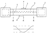
- the only drawing shows a schematic arrangement of an ultrasonic welding device according to the invention.
- an ultrasonic welding device has a first transducer 1 and a second transducer 2.
- the two transducers 1, 2 are connected to a resonator 3.
- the coupling takes place on the two end faces of the resonator 3.
- the transducers 1, 2 have a vibration maximum M at the coupling point.
- the resonator 3 has the length two lambda / 2, so that a vibration maximum M is also formed in the middle of the transducer.
- the amplitude curve is shown schematically below the resonator 3.
- a workpiece to be welded is pressed against the resonator 3 with a pressure P.
- the workpiece 4 is arranged so that the center of the workpiece 4 is at the maximum vibration M. It is thus possible to use the maximum amplitude of the ultrasonic vibration.
- the workpiece 4 In a conventional ultrasonic welding device, the workpiece 4 would have to be arranged next to the oscillation maximum M, since the resonator rod only extends up to the oscillation maximum M.
Landscapes
- Engineering & Computer Science (AREA)
- Mechanical Engineering (AREA)
- Pressure Welding/Diffusion-Bonding (AREA)
- Apparatuses For Generation Of Mechanical Vibrations (AREA)
- Lining Or Joining Of Plastics Or The Like (AREA)
- Manufacturing Of Electrical Connectors (AREA)
- Ultra Sonic Daignosis Equipment (AREA)
Abstract
Description
Die Erfindung betrifft ein Ultraschallschweißgerät mit einem longitudinale Schwingungen ausführenden ersten Schallwandler und einem stabförmigen Resonator der Länge lambda/2 oder einem ganzzahligen Vielfachen davon, welcher mit dem Schallwandler an einer Stirnseite gekoppelt ist.The invention relates to an ultrasonic welding device with a first sound transducer that executes longitudinal vibrations and a rod-shaped resonator of length lambda / 2 or an integral multiple thereof, which is coupled to the sound transducer on one end face.
Ultraschallschweißgeräte finden in der heutigen Zeit eine immer breitere Anwendung. So können mittels Ultraschall neben Kunststoffen auch Metalle wie beispielsweise Aluminium oder Kupfer geschweißt werden.Ultrasonic welding devices are used more and more in today's world. In addition to plastics, ultrasound can also be used to weld metals such as aluminum or copper.
Will man beispielsweise zwei Metalle miteinander verschweißen, so muß man sie mit hohem Druck zusammenpressen und ihre Struktur mittels Ultraschall in Schwingungen versetzen. Dies geschieht regelmäßig dadurch, daß die Metalle mit hohem Druck gegen einen Stab gedrückt werden, der mit einer Frequenz im Ultraschallbereich schwingt. Je höher die Schwingungsamplitude ist, umso geringer kann der statische Druck eingestellt werden. Es ist daher erstrebenswert, die zu verschweißenden Gegenstände mit möglichst großer Amplitude zu erregen.For example, if you want to weld two metals together, you have to press them together with high pressure and set their structure to vibrate using ultrasound. This happens regularly in that the metals are pressed with high pressure against a rod that vibrates with a frequency in the ultrasonic range. The higher the vibration amplitude, the lower the static pressure can be set. It is therefore desirable to excite the objects to be welded with the greatest possible amplitude.
Je größer die Amplitude ist, desto größer ist auch die Energie, die an die zu verschweißenden Gegenstände abgegeben wird. Somit ist es ebenfalls erstrebenswert, möglichst viel Energie an die Schweißstelle zu bringen.The greater the amplitude, the greater the energy that is released to the objects to be welded. It is therefore also desirable to bring as much energy as possible to the weld.
Bei herkömmlichen Ultraschallschweißgeräten ist die Energiezufuhr durch den zur Verfügung stehenden Wandler begrenzt. Aufgrund baulicher Gegebenheiten können nicht Wandler mit beliebig hoher Energie verwendet werden. Die bei Ultraschallschweißgeräten zur Verfügung stehende Energie und somit die Größe der Schweißnaht ist daher begrenzt.In conventional ultrasonic welding devices, the energy supply is limited by the converter available. Due to structural conditions, it is not possible to use transducers with any energy. The energy available with ultrasonic welding devices and thus the size of the weld seam is therefore limited.
Aus der DT 2 253 528 ist eine Vorrichtung zum Schweißen mit Ultraschall bekannt, bei der dem Schweißgut die Schwingungsenergie über zwei mechanisch nicht miteinander gekoppelte gleichphasig oder gegenphasig schwingende Erreger zugeführt wird. Bei den Erregern handelt es sich um Ultraschallwandler, welche jeweils an einem Ende einer Sonotrode angeordnet sind. Zwei zu verschweißende Werkstücke werden zwischen die Sonotrodenspitzen angeordnet. Die beiden Sonotrodenspitzen und damit die beiden zu verschweißenden Werkstücke werden durch eine Kraft aufeinander gedrückt.From DT 2 253 528 a device for welding with ultrasound is known, in which the weld metal is supplied with the vibration energy via two mechanically non-coupled exciters which oscillate in phase or in opposite phase. The exciters are ultrasonic transducers, which are each arranged at one end of a sonotrode. Two workpieces to be welded are placed between the sonotrode tips. The two sonotrode tips and thus the two workpieces to be welded are pressed together by a force.
Zwischen den beiden Sonotrodenspitzen kann auch ein Werkstück angeordnet sein, in welches dann die Energie von beiden Sonotroden eingeleitet wird. Das durch die Sonotroden bewegte Werkstück wird mittels einer äußeren Kraft auf ein sich in Ruhe befindliches Werkstück gedrückt.A workpiece can also be arranged between the two sonotrode tips, into which the energy from both sonotrodes is then introduced. The workpiece moved by the sonotrodes is pressed by an external force onto a workpiece that is at rest.
Es ist Aufgabe der Erfindung, ein eingangs genanntes Ultraschallschweißgerät so auszubilden, daß die Energie, die zum Schweißen zur Verfügung steht, vergrößert wird.It is an object of the invention to design an ultrasonic welding device mentioned at the outset in such a way that the energy available for welding is increased.
Die Lösung dieser Aufgabe ergibt sich aus den Merkmalen des Anspruchs 1. Vorteilhafte Weiterbildungen der Erfindung ergeben sich aus den Unteransprüchen.This object is achieved from the features of claim 1. Advantageous further developments of the invention result from the subclaims.
Gemäß der Erfindung ist bei einem eingangs genannten Ultraschallschweißgerät an der freien Stirnseite des Resonators ein zweiter longitudinale Schwingungen ausführender Schallwandler angekoppelt, welcher zum ersten Schallwandler synchron schwingt. Der zweite Schallwandler gibt seinerseits Energie an den Resonator ab. Hierdurch verdoppelt sich die Energie, die zum Schweißen zur Verfügung steht, nahezu. Es können somit größere Gegenstände miteinander verschweißt werden.According to the invention, in the case of an ultrasonic welding device mentioned at the outset, a second longitudinal vibrating transducer is coupled to the free end face of the resonator and vibrates synchronously with the first sound transducer. The second sound transducer in turn emits energy to the resonator. This almost doubles the energy available for welding. Larger objects can thus be welded together.
Mit der erfindungsgemäßen Vorrichtung erreicht man aber auch, daß, wenn kein erhöhter Energiebedarf zum Schweißen besteht, kleinere Wandler verwendet werden können, wodurch das Ultraschallschweißgerät eine günstigere Bauform erhält.With the device according to the invention, however, it is also achieved that, if there is no increased energy requirement for welding, smaller transducers can be used, as a result of which the ultrasonic welding device is given a more favorable design.
Ein weiterer Vorteil der erfindungsgemäßen Ausgestaltung eines Ultraschallschweißgeräts ist, daß die Werkstücke im Schwingungsmaximum an den Resonator gepreßt werden können. Bei herkömmlichen Ultraschallschweißgeräten hingegen können die Werkstücke, ausgehend vom Schwingungsmaximum des Resonators an der offenen Stirnseite, nur neben dem Schwingungsmaximum angeordnet werden.Another advantage of the design of an ultrasonic welding device according to the invention is that the workpieces can be pressed against the resonator at the maximum vibration. With conventional ultrasonic welding machines, however, the workpieces can only be arranged next to the maximum vibration, starting from the maximum vibration of the resonator on the open end face.
Eine besondere Ausführungsform der Erfindung sieht vor, daß die Länge des Resonators einem gradzahligen Vielfachen von lambda/2 entspricht. Hierdurch befindet sich genau in der Mitte zwischen den beiden Wandlern ein Schwingungsmaximum. Das heißt, die Stelle, an der die zu schweißenden Gegenstände gegen den Resonator gedrückt werden, befindet sich in der Mitte zwischen den beiden Wandlern, wodurch sie gut zugänglich ist. Des weiteren kann bei einer solchen Anordnung das Ultraschallschweißgerät symmetrisch ausgebildet werden.A special embodiment of the invention provides that the length of the resonator corresponds to an even multiple of lambda / 2. This is located exactly in the middle between the two converters a maximum vibration. This means that the point at which the objects to be welded are pressed against the resonator is in the middle between the two transducers, which makes them easily accessible. Furthermore, with such an arrangement, the ultrasonic welding device can be made symmetrical.
Bei einer weiteren Ausführungsform der Erfindung erfolgt die Ankopplung des Resonators an die Wandler mtitels Transformationsstücken. Hierdurch kann die Amplitude, mit der die Wandler an den Resonator angekoppelt werden, auf optimale Werte eingestellt werden.In a further embodiment of the invention, the resonator is coupled to the transducer by means of transformation pieces. As a result, the amplitude with which the transducers are coupled to the resonator can be set to optimum values.
Eine weitere Ausführungsform der Erfindung sieht vor, daß die elektrische Leitung zum zweiten Wandler axial durch den Resonator erfolgt. Da als Resonator nicht nur Vollmaterial, sondern auch rohrförmiges Material verwendet werden kann, kann der Resonator jedenfalls mit einer axialen Bohrung versehen werden, durch die die elektrische Leitung zum zweiten Wandler geführt werden kann. Es ist somit auf vorteilhafte Weise möglich, den zweiten Wandler ohne störende, außen verlaufende Leitungen mit Energie zu versorgen.Another embodiment of the invention provides that the electrical conduction to the second transducer takes place axially through the resonator. Since not only solid material but also tubular material can be used as the resonator, the resonator can in any case be provided with an axial bore through which the electrical line can be led to the second converter. It is thus advantageously possible to supply the second converter with energy without any disruptive lines running outside.
Weitere Einzelheiten, Merkmale und Vorteile der vorliegenden Erfindung ergeben sich aus der nachfolgenden Beschreibung eines besonderen Ausführungsbeispiels unter Bezugnahme auf die Zeichnung.Further details, features and advantages of the present invention result from the following description of a particular exemplary embodiment with reference to the drawing.
Es zeigt die einzige Zeichnung eine schematische Anordnung eines erfindungsgemäßen Ultraschallschweißgeräts.The only drawing shows a schematic arrangement of an ultrasonic welding device according to the invention.
Wie der Figur zu entnehmen ist, weist ein Ultraschallschweißgerät einen ersten Wandler 1 und einen zweiten Wandler 2 auf. Die beiden Wandler 1, 2 sind mit einem Resonator 3 verbunden. Die Ankopplung erfolgt an den beiden Stirnseiten des Resonators 3. Die Wandler 1, 2 haben an der Koppelstelle ein Schwingungsmaximum M. Der Resonator 3 hat die Länge zwei lambda/2, so daß sich auch in der Mitte des Wandlers ein Schwingungsmaximum M ausbildet. Der Amplitudenverlauf ist unterhalb des Resonators 3 schematisch dargestellt.As can be seen from the figure, an ultrasonic welding device has a first transducer 1 and a second transducer 2. The two transducers 1, 2 are connected to a resonator 3. The coupling takes place on the two end faces of the resonator 3. The transducers 1, 2 have a vibration maximum M at the coupling point. The resonator 3 has the length two lambda / 2, so that a vibration maximum M is also formed in the middle of the transducer. The amplitude curve is shown schematically below the resonator 3.
In der Mitte des Wandlers wird ein zu schweißendes Werkstück mit einem Druck P an den Resonator 3 gepreßt. Das Werkstück 4 ist so angeordnet, daß sich die Mitte des Werkstücks 4 im Schwingungsmaximum M befindet. Es ist somit möglich, die maximale Amplitude der Ultraschallschwingung auszunutzen.In the center of the transducer, a workpiece to be welded is pressed against the resonator 3 with a pressure P. The workpiece 4 is arranged so that the center of the workpiece 4 is at the maximum vibration M. It is thus possible to use the maximum amplitude of the ultrasonic vibration.
Bei einem herkömmlichen Ultraschallschweißgerät müßte das Werkstück 4 neben dem Schwingungsmaximum M angeordnet werden, da der Resonatorstab sich nur bis zum Schwingungsmaximum M erstreckt. Zur Verdeutlichung wurde ein Werkstück 4' in die Zeichnung aufgenommen, welches so angeordnet ist, wie es bei einem herkömmlichen Ultraschallschweißgerät angeordnet werden müßte.In a conventional ultrasonic welding device, the workpiece 4 would have to be arranged next to the oscillation maximum M, since the resonator rod only extends up to the oscillation maximum M. For the sake of clarity, a workpiece 4 'has been included in the drawing, which is arranged as it should be in a conventional ultrasonic welding device.
Claims (4)
- An ultrasonic welding apparatus having a first sound transducer (1) for producing longitudinal oscillations of a wavelength lambda and a bar-shaped resonator (3) of a length lambda/2 or a multiple thereof, which is coupled to the sound transducer (1) at one end, characterized in that coupled to the free end of the resonator (3) is a second sound transducer (2) for producing longitudinal oscillations, which oscillates synchronously with the first oscillator (1).
- An ultrasonic welding apparatus according to claim 1 characterised in that the length of the resonator (3) corresponds to an even-numbered multiple of lambda/2.
- An ultrasonic welding apparatus according to claim 1 or claim 2 characterised in that coupling of the resonator (3) to the transducers (1, 2) is effected by means of transformation portions.
- An ultrasonic welding apparatus according to one of claims 1 to 3 characterized in that the feed of current to the second sound transducer (2) is effected axially through the resonator (3).
Applications Claiming Priority (2)
| Application Number | Priority Date | Filing Date | Title |
|---|---|---|---|
| DE4344186 | 1993-12-23 | ||
| DE4344186A DE4344186C1 (en) | 1993-12-23 | 1993-12-23 | Ultrasonic welding apparatus |
Publications (3)
| Publication Number | Publication Date |
|---|---|
| EP0659516A1 EP0659516A1 (en) | 1995-06-28 |
| EP0659516B1 true EP0659516B1 (en) | 1997-03-05 |
| EP0659516B2 EP0659516B2 (en) | 2000-07-26 |
Family
ID=6506019
Family Applications (1)
| Application Number | Title | Priority Date | Filing Date |
|---|---|---|---|
| EP94117134A Expired - Lifetime EP0659516B2 (en) | 1993-12-23 | 1994-10-29 | Ultrasonic welding apparatus |
Country Status (5)
| Country | Link |
|---|---|
| EP (1) | EP0659516B2 (en) |
| JP (1) | JPH07276068A (en) |
| AT (1) | ATE149399T1 (en) |
| DE (2) | DE4344186C1 (en) |
| ES (1) | ES2098847T5 (en) |
Families Citing this family (5)
| Publication number | Priority date | Publication date | Assignee | Title |
|---|---|---|---|---|
| DE4439470C2 (en) * | 1994-11-08 | 1999-05-20 | Herrmann Ultraschalltechnik | Device for ultrasound machining of a workpiece |
| DE19545132C2 (en) * | 1995-12-01 | 1998-05-20 | Branson Ultraschall | Orbital friction welding machine |
| JP3290632B2 (en) * | 1999-01-06 | 2002-06-10 | 株式会社アルテクス | Ultrasonic vibration bonding equipment |
| KR100330668B1 (en) * | 1999-08-26 | 2002-03-29 | 이천웅 | a twist vibration generating apparatus of ultrasonic welding machine |
| CN102145434A (en) * | 2010-02-05 | 2011-08-10 | 严锦璇 | Double-head synchronous ultrasonic metal welding device |
Family Cites Families (3)
| Publication number | Priority date | Publication date | Assignee | Title |
|---|---|---|---|---|
| US3166840A (en) † | 1961-06-28 | 1965-01-26 | Aeroprojects Inc | Apparatus and method for introducing high levels of vibratory energy to a work area |
| US3209448A (en) † | 1962-03-12 | 1965-10-05 | Sonobond Corp | Vibratory welding method and apparatus |
| DE2253528A1 (en) * | 1972-11-02 | 1974-05-09 | Reimar Prof Dr Phil Pohlman | Ultrasonic metal welding intensification - by introducing oscillatory energy by two sonotrodes without mechanical coupling |
-
1993
- 1993-12-23 DE DE4344186A patent/DE4344186C1/en not_active Expired - Lifetime
-
1994
- 1994-10-29 ES ES94117134T patent/ES2098847T5/en not_active Expired - Lifetime
- 1994-10-29 EP EP94117134A patent/EP0659516B2/en not_active Expired - Lifetime
- 1994-10-29 DE DE59401935T patent/DE59401935D1/en not_active Expired - Lifetime
- 1994-10-29 AT AT94117134T patent/ATE149399T1/en active
- 1994-12-21 JP JP6318839A patent/JPH07276068A/en active Pending
Also Published As
| Publication number | Publication date |
|---|---|
| DE59401935D1 (en) | 1997-04-10 |
| EP0659516B2 (en) | 2000-07-26 |
| DE4344186C1 (en) | 1995-01-26 |
| EP0659516A1 (en) | 1995-06-28 |
| JPH07276068A (en) | 1995-10-24 |
| ATE149399T1 (en) | 1997-03-15 |
| ES2098847T5 (en) | 2000-11-01 |
| ES2098847T3 (en) | 1997-05-01 |
Similar Documents
| Publication | Publication Date | Title |
|---|---|---|
| DE69406165T2 (en) | Ultrasonic sealing device | |
| DE2532029A1 (en) | METHOD FOR APPLYING A LIQUID WITH HIGH-FREQUENCY SOUND ENERGY AND DEVICE FOR CARRYING OUT THE METHOD | |
| DE2312446A1 (en) | ELECTROMECHANICAL VIBRATOR, IN PARTICULAR FOR WELDING METALS | |
| EP0857088A1 (en) | Device for transferring ultrasonic energy into a liquid or pasty medium | |
| DE10295945B4 (en) | Symmetrical rotary ultrasonic horn | |
| EP2945793B1 (en) | Ultrasound welding device comprising vibration-decoupled counter tool | |
| DE2628203A1 (en) | PROCESS FOR ULTRASONIC WELDING OF TWO THERMOPLASTIC WORKPIECES | |
| DE1948844A1 (en) | Horn for sonic or ultrasonic processing | |
| EP0659516B1 (en) | Ultrasonic welding apparatus | |
| DE1289344B (en) | Working transducer | |
| DE2743018A1 (en) | PROCESS AND EQUIPMENT FOR CONNECTING METALLIC WORKPIECES WITH HIGH FREQUENCY ENERGY (HF WELDING PROCESS AND DEVICE) | |
| DE2047883B2 (en) | Vibration transmitter for an ultrasonic device | |
| DE19859355C2 (en) | Device for joining metallic materials | |
| WO2000029178A1 (en) | Ultrasonic cutting device | |
| EP0895489B1 (en) | Process and apparatus for cleaning thread- or strip-shaped articles, in particular wire | |
| DE1704178A1 (en) | Process for the continuous seam welding of foils made of thermoplastic material by means of ultrasound | |
| WO1999046061A1 (en) | Method for activating a sieve frame with ultrasounds | |
| DE2414474C2 (en) | ||
| DE10114672A1 (en) | Ultrasonic vibrator e.g. for machine tool, has vibration element in form of plate to which ultrasonic vibration generator is attached on one side of plate | |
| DE6901110U (en) | ELECTROMECHANICAL ULTRASONIC ENERGY GENERATOR, IN PARTICULAR FOR WELDING PLASTIC STRAPS. | |
| EP3713682B1 (en) | Ultrasonic vibrating unit with damping | |
| DE748684C (en) | Device for electrical spot welding, in particular of aluminum alloys | |
| EP2663416B1 (en) | Method and device for producing a vibrating motion of a mass | |
| DE2355333B2 (en) | Ultrasonic processing device, in particular ultrasonic welding device | |
| CH671530A5 (en) | Ultrasonic machining tool for milling or boring applications - has tool crown subjected to both axial and radial oscillations |
Legal Events
| Date | Code | Title | Description |
|---|---|---|---|
| PUAI | Public reference made under article 153(3) epc to a published international application that has entered the european phase |
Free format text: ORIGINAL CODE: 0009012 |
|
| AK | Designated contracting states |
Kind code of ref document: A1 Designated state(s): AT BE CH DE ES FR GB IT LI NL PT SE |
|
| 17P | Request for examination filed |
Effective date: 19950524 |
|
| 17Q | First examination report despatched |
Effective date: 19960119 |
|
| GRAG | Despatch of communication of intention to grant |
Free format text: ORIGINAL CODE: EPIDOS AGRA |
|
| GRAH | Despatch of communication of intention to grant a patent |
Free format text: ORIGINAL CODE: EPIDOS IGRA |
|
| GRAH | Despatch of communication of intention to grant a patent |
Free format text: ORIGINAL CODE: EPIDOS IGRA |
|
| GRAA | (expected) grant |
Free format text: ORIGINAL CODE: 0009210 |
|
| AK | Designated contracting states |
Kind code of ref document: B1 Designated state(s): AT BE CH DE ES FR GB IT LI NL PT SE |
|
| REF | Corresponds to: |
Ref document number: 149399 Country of ref document: AT Date of ref document: 19970315 Kind code of ref document: T |
|
| REG | Reference to a national code |
Ref country code: CH Ref legal event code: NV Representative=s name: DR. CONRAD A. RIEDERER PATENTANWALT Ref country code: CH Ref legal event code: EP |
|
| GBT | Gb: translation of ep patent filed (gb section 77(6)(a)/1977) |
Effective date: 19970305 |
|
| REF | Corresponds to: |
Ref document number: 59401935 Country of ref document: DE Date of ref document: 19970410 |
|
| REG | Reference to a national code |
Ref country code: ES Ref legal event code: FG2A Ref document number: 2098847 Country of ref document: ES Kind code of ref document: T3 |
|
| ITF | It: translation for a ep patent filed | ||
| REG | Reference to a national code |
Ref country code: PT Ref legal event code: SC4A Free format text: AVAILABILITY OF NATIONAL TRANSLATION Effective date: 19970327 |
|
| ET | Fr: translation filed | ||
| PLAV | Examination of admissibility of opposition |
Free format text: ORIGINAL CODE: EPIDOS OPEX |
|
| PLBI | Opposition filed |
Free format text: ORIGINAL CODE: 0009260 |
|
| PLBF | Reply of patent proprietor to notice(s) of opposition |
Free format text: ORIGINAL CODE: EPIDOS OBSO |
|
| 26 | Opposition filed |
Opponent name: SIEMENS AG Effective date: 19971205 |
|
| NLR1 | Nl: opposition has been filed with the epo |
Opponent name: SIEMENS AG |
|
| PLBF | Reply of patent proprietor to notice(s) of opposition |
Free format text: ORIGINAL CODE: EPIDOS OBSO |
|
| PLAW | Interlocutory decision in opposition |
Free format text: ORIGINAL CODE: EPIDOS IDOP |
|
| PLAW | Interlocutory decision in opposition |
Free format text: ORIGINAL CODE: EPIDOS IDOP |
|
| PUAH | Patent maintained in amended form |
Free format text: ORIGINAL CODE: 0009272 |
|
| STAA | Information on the status of an ep patent application or granted ep patent |
Free format text: STATUS: PATENT MAINTAINED AS AMENDED |
|
| 27A | Patent maintained in amended form |
Effective date: 20000726 |
|
| AK | Designated contracting states |
Kind code of ref document: B2 Designated state(s): AT BE CH DE ES FR GB IT LI NL PT SE |
|
| REG | Reference to a national code |
Ref country code: CH Ref legal event code: AEN Free format text: AUFRECHTERHALTUNG DES PATENTES IN GEAENDERTER FORM |
|
| GBTA | Gb: translation of amended ep patent filed (gb section 77(6)(b)/1977) | ||
| ET3 | Fr: translation filed ** decision concerning opposition | ||
| NLR2 | Nl: decision of opposition | ||
| ITF | It: translation for a ep patent filed | ||
| REG | Reference to a national code |
Ref country code: ES Ref legal event code: DC2A Kind code of ref document: T5 Effective date: 20000911 |
|
| NLR3 | Nl: receipt of modified translations in the netherlands language after an opposition procedure | ||
| REG | Reference to a national code |
Ref country code: GB Ref legal event code: IF02 |
|
| REG | Reference to a national code |
Ref country code: CH Ref legal event code: NV Representative=s name: RIEDERER HASLER & PARTNER PATENTANWAELTE AG |
|
| REG | Reference to a national code |
Ref country code: DE Ref legal event code: R082 Ref document number: 59401935 Country of ref document: DE Representative=s name: PATENTANWAELTE DIMMERLING & HUWER, DE |
|
| PGFP | Annual fee paid to national office [announced via postgrant information from national office to epo] |
Ref country code: AT Payment date: 20131021 Year of fee payment: 20 Ref country code: DE Payment date: 20131031 Year of fee payment: 20 Ref country code: SE Payment date: 20131022 Year of fee payment: 20 Ref country code: FR Payment date: 20131018 Year of fee payment: 20 Ref country code: CH Payment date: 20131023 Year of fee payment: 20 Ref country code: PT Payment date: 20130429 Year of fee payment: 20 Ref country code: GB Payment date: 20131022 Year of fee payment: 20 Ref country code: BE Payment date: 20131021 Year of fee payment: 20 |
|
| PGFP | Annual fee paid to national office [announced via postgrant information from national office to epo] |
Ref country code: ES Payment date: 20131022 Year of fee payment: 20 Ref country code: IT Payment date: 20131025 Year of fee payment: 20 Ref country code: NL Payment date: 20131021 Year of fee payment: 20 |
|
| REG | Reference to a national code |
Ref country code: DE Ref legal event code: R071 Ref document number: 59401935 Country of ref document: DE |
|
| REG | Reference to a national code |
Ref country code: NL Ref legal event code: V4 Effective date: 20141029 Ref country code: PT Ref legal event code: MM4A Free format text: MAXIMUM VALIDITY LIMIT REACHED Effective date: 20141029 |
|
| REG | Reference to a national code |
Ref country code: CH Ref legal event code: PL |
|
| REG | Reference to a national code |
Ref country code: GB Ref legal event code: PE20 Expiry date: 20141028 |
|
| REG | Reference to a national code |
Ref country code: SE Ref legal event code: EUG |
|
| REG | Reference to a national code |
Ref country code: AT Ref legal event code: MK07 Ref document number: 149399 Country of ref document: AT Kind code of ref document: T Effective date: 20141029 |
|
| REG | Reference to a national code |
Ref country code: ES Ref legal event code: FD2A Effective date: 20150108 |
|
| PG25 | Lapsed in a contracting state [announced via postgrant information from national office to epo] |
Ref country code: ES Free format text: LAPSE BECAUSE OF EXPIRATION OF PROTECTION Effective date: 20141030 Ref country code: GB Free format text: LAPSE BECAUSE OF EXPIRATION OF PROTECTION Effective date: 20141028 Ref country code: PT Free format text: LAPSE BECAUSE OF EXPIRATION OF PROTECTION Effective date: 20141105 |