EP3556423A1 - Implant injection device provided with a rack and pinion transmission - Google Patents
Implant injection device provided with a rack and pinion transmission Download PDFInfo
- Publication number
- EP3556423A1 EP3556423A1 EP19169959.4A EP19169959A EP3556423A1 EP 3556423 A1 EP3556423 A1 EP 3556423A1 EP 19169959 A EP19169959 A EP 19169959A EP 3556423 A1 EP3556423 A1 EP 3556423A1
- Authority
- EP
- European Patent Office
- Prior art keywords
- implant
- rack
- injection
- injection device
- push rod
- Prior art date
- Legal status (The legal status is an assumption and is not a legal conclusion. Google has not performed a legal analysis and makes no representation as to the accuracy of the status listed.)
- Pending
Links
- 239000007943 implant Substances 0.000 title claims abstract description 215
- 238000002347 injection Methods 0.000 title claims abstract description 190
- 239000007924 injection Substances 0.000 title claims abstract description 190
- 230000005540 biological transmission Effects 0.000 title claims abstract description 53
- 238000011144 upstream manufacturing Methods 0.000 claims abstract description 13
- 230000033001 locomotion Effects 0.000 claims description 15
- 238000005452 bending Methods 0.000 claims description 2
- 238000006073 displacement reaction Methods 0.000 abstract description 9
- 239000000463 material Substances 0.000 description 4
- 208000031968 Cadaver Diseases 0.000 description 3
- 241001080024 Telles Species 0.000 description 2
- 208000027418 Wounds and injury Diseases 0.000 description 2
- 230000006378 damage Effects 0.000 description 2
- 208000014674 injury Diseases 0.000 description 2
- 238000003780 insertion Methods 0.000 description 2
- 230000037431 insertion Effects 0.000 description 2
- 239000002184 metal Substances 0.000 description 2
- 230000002093 peripheral effect Effects 0.000 description 2
- 239000004033 plastic Substances 0.000 description 2
- 229920003023 plastic Polymers 0.000 description 2
- -1 polyethylene Polymers 0.000 description 2
- 239000007787 solid Substances 0.000 description 2
- 229910001220 stainless steel Inorganic materials 0.000 description 2
- 239000010935 stainless steel Substances 0.000 description 2
- 210000003813 thumb Anatomy 0.000 description 2
- 241001644893 Entandrophragma utile Species 0.000 description 1
- 241000124008 Mammalia Species 0.000 description 1
- 239000004698 Polyethylene Substances 0.000 description 1
- 239000004743 Polypropylene Substances 0.000 description 1
- 229910000831 Steel Inorganic materials 0.000 description 1
- 150000001875 compounds Chemical class 0.000 description 1
- 229940082150 encore Drugs 0.000 description 1
- 210000003811 finger Anatomy 0.000 description 1
- 230000005484 gravity Effects 0.000 description 1
- 239000007788 liquid Substances 0.000 description 1
- 239000012528 membrane Substances 0.000 description 1
- 229920000573 polyethylene Polymers 0.000 description 1
- 229920001155 polypropylene Polymers 0.000 description 1
- 230000001681 protective effect Effects 0.000 description 1
- 230000005236 sound signal Effects 0.000 description 1
- 239000010959 steel Substances 0.000 description 1
- 239000012815 thermoplastic material Substances 0.000 description 1
- 230000001131 transforming effect Effects 0.000 description 1
- 238000012800 visualization Methods 0.000 description 1
Images


Classifications
-
- A—HUMAN NECESSITIES
- A61—MEDICAL OR VETERINARY SCIENCE; HYGIENE
- A61M—DEVICES FOR INTRODUCING MEDIA INTO, OR ONTO, THE BODY; DEVICES FOR TRANSDUCING BODY MEDIA OR FOR TAKING MEDIA FROM THE BODY; DEVICES FOR PRODUCING OR ENDING SLEEP OR STUPOR
- A61M37/00—Other apparatus for introducing media into the body; Percutany, i.e. introducing medicines into the body by diffusion through the skin
- A61M37/0069—Devices for implanting pellets, e.g. markers or solid medicaments
-
- A—HUMAN NECESSITIES
- A61—MEDICAL OR VETERINARY SCIENCE; HYGIENE
- A61B—DIAGNOSIS; SURGERY; IDENTIFICATION
- A61B17/00—Surgical instruments, devices or methods, e.g. tourniquets
- A61B17/34—Trocars; Puncturing needles
- A61B17/3468—Trocars; Puncturing needles for implanting or removing devices, e.g. prostheses, implants, seeds, wires
-
- A—HUMAN NECESSITIES
- A61—MEDICAL OR VETERINARY SCIENCE; HYGIENE
- A61F—FILTERS IMPLANTABLE INTO BLOOD VESSELS; PROSTHESES; DEVICES PROVIDING PATENCY TO, OR PREVENTING COLLAPSING OF, TUBULAR STRUCTURES OF THE BODY, e.g. STENTS; ORTHOPAEDIC, NURSING OR CONTRACEPTIVE DEVICES; FOMENTATION; TREATMENT OR PROTECTION OF EYES OR EARS; BANDAGES, DRESSINGS OR ABSORBENT PADS; FIRST-AID KITS
- A61F2/00—Filters implantable into blood vessels; Prostheses, i.e. artificial substitutes or replacements for parts of the body; Appliances for connecting them with the body; Devices providing patency to, or preventing collapsing of, tubular structures of the body, e.g. stents
- A61F2/0095—Packages or dispensers for prostheses or other implants
-
- A—HUMAN NECESSITIES
- A61—MEDICAL OR VETERINARY SCIENCE; HYGIENE
- A61M—DEVICES FOR INTRODUCING MEDIA INTO, OR ONTO, THE BODY; DEVICES FOR TRANSDUCING BODY MEDIA OR FOR TAKING MEDIA FROM THE BODY; DEVICES FOR PRODUCING OR ENDING SLEEP OR STUPOR
- A61M5/00—Devices for bringing media into the body in a subcutaneous, intra-vascular or intramuscular way; Accessories therefor, e.g. filling or cleaning devices, arm-rests
- A61M5/50—Devices for bringing media into the body in a subcutaneous, intra-vascular or intramuscular way; Accessories therefor, e.g. filling or cleaning devices, arm-rests having means for preventing re-use, or for indicating if defective, used, tampered with or unsterile
- A61M5/5086—Devices for bringing media into the body in a subcutaneous, intra-vascular or intramuscular way; Accessories therefor, e.g. filling or cleaning devices, arm-rests having means for preventing re-use, or for indicating if defective, used, tampered with or unsterile for indicating if defective, used, tampered with or unsterile
-
- A—HUMAN NECESSITIES
- A61—MEDICAL OR VETERINARY SCIENCE; HYGIENE
- A61B—DIAGNOSIS; SURGERY; IDENTIFICATION
- A61B17/00—Surgical instruments, devices or methods, e.g. tourniquets
- A61B17/34—Trocars; Puncturing needles
- A61B2017/347—Locking means, e.g. for locking instrument in cannula
-
- A—HUMAN NECESSITIES
- A61—MEDICAL OR VETERINARY SCIENCE; HYGIENE
- A61B—DIAGNOSIS; SURGERY; IDENTIFICATION
- A61B90/00—Instruments, implements or accessories specially adapted for surgery or diagnosis and not covered by any of the groups A61B1/00 - A61B50/00, e.g. for luxation treatment or for protecting wound edges
- A61B90/03—Automatic limiting or abutting means, e.g. for safety
- A61B2090/033—Abutting means, stops, e.g. abutting on tissue or skin
- A61B2090/034—Abutting means, stops, e.g. abutting on tissue or skin abutting on parts of the device itself
-
- A—HUMAN NECESSITIES
- A61—MEDICAL OR VETERINARY SCIENCE; HYGIENE
- A61B—DIAGNOSIS; SURGERY; IDENTIFICATION
- A61B90/00—Instruments, implements or accessories specially adapted for surgery or diagnosis and not covered by any of the groups A61B1/00 - A61B50/00, e.g. for luxation treatment or for protecting wound edges
- A61B90/08—Accessories or related features not otherwise provided for
- A61B2090/0814—Preventing re-use
-
- A—HUMAN NECESSITIES
- A61—MEDICAL OR VETERINARY SCIENCE; HYGIENE
- A61B—DIAGNOSIS; SURGERY; IDENTIFICATION
- A61B90/00—Instruments, implements or accessories specially adapted for surgery or diagnosis and not covered by any of the groups A61B1/00 - A61B50/00, e.g. for luxation treatment or for protecting wound edges
- A61B90/39—Markers, e.g. radio-opaque or breast lesions markers
- A61B2090/3987—Applicators for implanting markers
-
- A—HUMAN NECESSITIES
- A61—MEDICAL OR VETERINARY SCIENCE; HYGIENE
- A61B—DIAGNOSIS; SURGERY; IDENTIFICATION
- A61B90/00—Instruments, implements or accessories specially adapted for surgery or diagnosis and not covered by any of the groups A61B1/00 - A61B50/00, e.g. for luxation treatment or for protecting wound edges
- A61B90/90—Identification means for patients or instruments, e.g. tags
- A61B90/98—Identification means for patients or instruments, e.g. tags using electromagnetic means, e.g. transponders
-
- A—HUMAN NECESSITIES
- A61—MEDICAL OR VETERINARY SCIENCE; HYGIENE
- A61M—DEVICES FOR INTRODUCING MEDIA INTO, OR ONTO, THE BODY; DEVICES FOR TRANSDUCING BODY MEDIA OR FOR TAKING MEDIA FROM THE BODY; DEVICES FOR PRODUCING OR ENDING SLEEP OR STUPOR
- A61M2205/00—General characteristics of the apparatus
- A61M2205/27—General characteristics of the apparatus preventing use
- A61M2205/273—General characteristics of the apparatus preventing use preventing reuse, e.g. of disposables
-
- A—HUMAN NECESSITIES
- A61—MEDICAL OR VETERINARY SCIENCE; HYGIENE
- A61M—DEVICES FOR INTRODUCING MEDIA INTO, OR ONTO, THE BODY; DEVICES FOR TRANSDUCING BODY MEDIA OR FOR TAKING MEDIA FROM THE BODY; DEVICES FOR PRODUCING OR ENDING SLEEP OR STUPOR
- A61M2205/00—General characteristics of the apparatus
- A61M2205/58—Means for facilitating use, e.g. by people with impaired vision
- A61M2205/581—Means for facilitating use, e.g. by people with impaired vision by audible feedback
-
- A—HUMAN NECESSITIES
- A61—MEDICAL OR VETERINARY SCIENCE; HYGIENE
- A61M—DEVICES FOR INTRODUCING MEDIA INTO, OR ONTO, THE BODY; DEVICES FOR TRANSDUCING BODY MEDIA OR FOR TAKING MEDIA FROM THE BODY; DEVICES FOR PRODUCING OR ENDING SLEEP OR STUPOR
- A61M2205/00—General characteristics of the apparatus
- A61M2205/58—Means for facilitating use, e.g. by people with impaired vision
- A61M2205/582—Means for facilitating use, e.g. by people with impaired vision by tactile feedback
-
- A—HUMAN NECESSITIES
- A61—MEDICAL OR VETERINARY SCIENCE; HYGIENE
- A61M—DEVICES FOR INTRODUCING MEDIA INTO, OR ONTO, THE BODY; DEVICES FOR TRANSDUCING BODY MEDIA OR FOR TAKING MEDIA FROM THE BODY; DEVICES FOR PRODUCING OR ENDING SLEEP OR STUPOR
- A61M5/00—Devices for bringing media into the body in a subcutaneous, intra-vascular or intramuscular way; Accessories therefor, e.g. filling or cleaning devices, arm-rests
- A61M5/178—Syringes
- A61M5/31—Details
- A61M5/32—Needles; Details of needles pertaining to their connection with syringe or hub; Accessories for bringing the needle into, or holding the needle on, the body; Devices for protection of needles
- A61M5/3205—Apparatus for removing or disposing of used needles or syringes, e.g. containers; Means for protection against accidental injuries from used needles
- A61M5/321—Means for protection against accidental injuries by used needles
- A61M5/322—Retractable needles, i.e. disconnected from and withdrawn into the syringe barrel by the piston
Definitions
- the invention relates to the technical field of injecting one or more implants into the body of a patient.
- Implant injection devices including a hollow needle attached to a housing receiving an implant.
- the implant is injected by means of a push rod, which pushes the implant through the hollow needle and beyond to allow injection of the implant into the body of a patient.
- actuation sliding support does not easily allow the user to inject multiple implants. Indeed, this actuation is generally performed by the thumb of the user, which has a reduced stroke for actuation that is not sufficient to the stroke necessary for the injection of an implant of great length and / or for the successive injection of two or more implants.
- actuation does not make it possible to maintain high injection precision over a large stroke, and does not in particular make it possible to stop the injection when the injection of an implant is performed, for example to orient the needle. injection in another direction for a second implant so as not to inject over too long. Indeed, the risk of starting unwantedly the injection of an implant following the already injected implant exists with such an actuation. This is undesirable to ensure correct injection, especially to prevent rupture of at least one of the implants or injury to the patient.
- these implant injection devices do not allow to easily inject a long implant or a plurality of implants.
- the present invention aims in particular to provide an implant injection device, which can easily inject a long implant and / or a plurality of implants.
- an easy implant injector to handle and assemble, achieving a pleasant motion transmission for a user. Indeed, by one or more movements of small amplitude, the user can actuate the push rod over a long length thanks to the rack transmission, allowing for example to inject a long implant or a plurality of implants.
- a rack-and-pinion transmission mechanism preferably comprises a toothed rectilinear element cooperating with a toothed wheel, for transforming a rotational movement into a translation movement or vice versa.
- implant is preferably intended to mean a pharmaceutical compound in the solid or semi-solid state, for example in the form of an encapsulated liquid, and / or an electronic component, for example an electronic chip that may be of RFID type.
- patient or “subject” is generally understood to mean a living being, for example a mammal, in particular a human being. The user is usually a different person than the patient, but it is possible that the user is the patient himself.
- the distal direction designates the direction farthest from the fingers of a user, that is to say, the closest to the skin or the surface of a patient at the time of a injection
- the proximal direction refers to the direction opposite to the distal direction.
- the distal direction and the distal direction are the direction and the direction that go to the "front" of the implant injection device, direction otherwise called injection direction.
- the distal end of a patch corresponds to the end on the side of the injection needle, and the proximal end is the opposite end.
- the injection axis, bearing the direction of injection corresponds to the axis of the implant injection device, defined by the axis of the injection needle.
- downstream direction is a direction opposite to the “upstream” direction and corresponds to the direction oriented in the direction of the distal end of the implant injection device, that is to say towards the injection site, towards the end configured to be in contact with the injection site of the implant.
- the "downstream” direction can also be called the injection direction.
- upstream and downstream are relative to the distal and proximal directions, a downstream element being disposed further in the distal direction than an upstream element.
- the implant injection device may further comprise one or more of the following features, taken alone or in combination.
- an implant injection device comprises an injection needle 9 (visible on the figure 2 ) carried by a gripping case 7 and protected by a cap 3 (visible on the figure 1 ), a reception body 11 (visible on the figure 2 ), at least one implant, injection means 5 and a gripping housing 7.
- the implant injection device 1 is configured to inject one or more implants into the body of a patient via the visible injection needle 9. Although in the following, the example is illustrated with two implants, the implant injection device 1 is also applicable to a single implant, or a number of implants greater than two, as for example three, four, five, ten implants.
- the injection needle 9 is hollow and is for example made of metal such as stainless steel.
- the injection needle 9 has a distal end beveled to facilitate its insertion into the body of the patient.
- the injection needle 9 carries a support member 13, which may be made of plastic material and is intended to limit the depth of insertion of the injection needle 9 in the body of the patient.
- the injection needle 9 is attached at its proximal end to the receiving body 11. It can be protected in the storage configuration by the cap 3.
- the cap 3 is a protective cap of the injection needle 9, it is here assembled on the gripping housing 7, by snapping its proximal end on the gripping housing 7.
- other means of assembly are possible, for example by screwing.
- the cap 3 is in this example in the form of ogive, may be provided with reliefs so as to facilitate its grip.
- the receiving body 11 is a receiving body of two implants. As illustrated on the figure 2 , the receiving body 11 is generally tubular and / or frustoconical, and houses the implants in its internal space, so that the implants are oriented towards the end of the injection needle 9, facing the the proximal end of the injection needle 9. In other words, the receiving body 11 is disposed upstream of the injection needle 9, and is intended to receive the implants so that the implants are arranged upstream of the injection needle 9, in the direction of injection of the injection needle 9.
- the receiving body 11 is configured to contain two implants, the two implants being arranged one behind the other, that is to say one upstream of the other, according to the direction of injection.
- the receiving body 11 may have, at its distal end, an implant retaining means, such as a membrane or a small narrowing of its internal diameter, for the purpose of preventing the fall of an implant through the needle. injection 9, for example under the action of the Earth's gravity force.
- the receiving body 11 may alternatively comprise, at its distal end, a flexible implant retaining element comprising an orifice of a diameter smaller than that of the implants, which is configured to deform and allow the passage of implants to the implant. injection needle 9 during the injection.
- the receiving body 11 advantageously comprises a window 15 (visible on the figure 2 ). Thus, a user is able to visually detect, through the window 15, the presence of the implants in the implant injection device 1 before performing the injection on a patient, after the withdrawal of the cap 3.
- the injection needle 9 and the receiving body 11 are patches with respect to the other, nevertheless it would be possible that the injection needle 9 and the receiving body 11 form two parts of the same part, for example by being made of material.
- the receiving body 11 is attached at its proximal end to the gripping casing 7, for example by snapping its proximal end onto the gripping casing 7, as illustrated in FIG. figure 3 .
- the receiving body 11 thus has a peripheral rib 16, which engages in a corresponding groove 18 carried by the gripping casing 7.
- other assembly means are possible, for example by screwing.
- the receiving body 11 could be made directly in the gripping housing 7, being integral with the latter.
- the receiving body 11 is made of a plastic material, possibly transparent.
- the outer gripping member 17, the distal plug 19 and the two supporting members 21, 23 are held in position relative to one another.
- the two support elements 21, 23 are assembled by snap-fitting of pins 25 (visible on the figure 3 ) carried by the male support member 21 in tubular housings 27 (visible on the figure 7 ) in the assembled state
- the distal plug 19 is in abutment against the distal end of the two support members 21, 23, and is connected to the outer member of the gripping 17 by latching protrusions 29, for example in the form of semi-cylindrical sections as illustrated in FIG. figure 5 in a corresponding inner peripheral groove of the outer gripping element 17.
- the injection means 5 make it possible to push the implant or implants through the injection needle 9 between an initial position and a final position in which the implant or implants are injected.
- the injection means 5 comprise a push rod 31 and actuating means 33 by a user.
- the push rod 31 is disposed upstream of the implants housed in the receiving body.
- the push rod 31 extends longitudinally and is configured to push the implants through the injection needle 9 between an initial position and a final position in which the implants are injected.
- the push rod 31 may be made of metal, for example steel, preferably stainless steel.
- the push rod 31 is disposed upstream of an implant which is itself the implant disposed the most upstream among the implants. .
- the push rod 31 is thus configured to push the implant, here the implants, through the injection needle 9 between an initial position and a final position.
- the implants are housed in the receiving body 11, and in the final position of the push rod 31, the implants are passed through the injection needle 9 and are located a priori in the body of a patient.
- the actuating means 33 by a user are configured to actuate a displacement of the push rod 31 from the initial position to the final position.
- the actuating means 33 comprise a rack transmission mechanism 35.
- the rack-and-pinion transmission mechanism 35 includes a first rack member 37 and a second rack member 39.
- the first rack member 37 is a rack and pinion member. It is thus configured to be driven by the user and forms a first rack-and-rack connection with a pinion 41.
- the pinion 41 comprises a first toothing 43 cooperating with the first rack member 37, and the pinion 41 comprises a second toothing 45 cooperating with the second rack member 39 configured to push the push rod 31 from the initial position to the position final.
- the pinion 41 thus forms a second rack-and-rack connection with the second rack element 39.
- the first set of teeth 43 and the second toothing 45 of the pinion 41 are formed respectively by a first gear 43 and a second gear 45, the first gear wheel 43 having a diameter smaller than the diameter of the second gear wheel 45.
- the number of teeth of the first toothing 43 is strictly less than the number of teeth of the second toothing 45, in order to achieve a reduction of the movement.
- the number of teeth of the first toothing 43 is between 5 and 15, preferably between 5 and 10, more preferably is close to or equal to 5, and / or the number of teeth of the second toothing 45 is included. between 6 and 30, preferably between 16 and 25, more preferably close to or equal to 18.
- the number of teeth of the first toothing 43 and the number of teeth of the second toothing 45 are preferably chosen so that the displacement ratio of the second rack member 39 relative to the movement of the first rack member 37 is between 2 and 10, preferably between 3 and 5, more preferably close to or equal to 3.6.
- the pinion 41 is pivotally mounted in the gripping housing 7.
- the pinion 41 comprises for this a pin at each of its ends, a pin being carried by the male support member 21, and a pin 46 being carried by the element
- the axis of rotation of the pinion 41 is substantially orthogonal to the longitudinal direction of the push rod 31, so that the movement of the second rack member 39 allows to push the push rod 31 from the initial position to the final position.
- the first rack member 37 further supports an actuation button 47, which is configured to be driven directly by the user.
- the actuating button 47 is assembled on the first rack member 37, for example by snap-fastening. It is understood that the first rack member 37 is in one piece with the actuating button 47.
- the actuating button 47 is slidably mounted in a direction substantially parallel to the longitudinal direction of the push rod 31.
- the first rack member 37 and the assembly formed by the male support member 21 and the female support member 23 form a sliding connection between them, in the longitudinal direction of the push rod 31.
- the second rack member 39 is a driven rack member. It is thus configured to be driven by the pinion 41 and forms a second rack-and-rack connection with the pinion 41.
- the second rack member 39 supports the push rod 31, the push rod 31 being for example fixed by clamping in a housing of the second rack member 39. Thus, when the second rack member 39 is driven, it pushes the push rod 31 in the injection direction from the initial position to the final position.
- the second rack member 39 is slidably mounted in a direction substantially parallel to the longitudinal direction of the push rod 31.
- the second rack member 39 and the assembly formed by the male support member 21 and the female support member 23 forms a slide connection therebetween, in the longitudinal direction of the push rod.
- the second rack member 39 slides in the longitudinal direction of the push rod, causing the push rod 31 to move in the distal direction.
- the push rod 31 then pushes at least one implant through the injection needle 9.
- the second rack member 39 does not continue its course.
- the gripping housing 7 then forms, in particular through the male support element 21, a stop for the second rack member 39.
- the user can inject an implant over too great length may injure the patient.
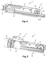
- the implant injection device 1 also comprises means 51 for indicating a position of the push rod 31 to the user, as illustrated, for example, on the figure 4 .
- the indication means 51 here comprise a first flexible tongue 53 carried by the gripping housing 7, in particular by the male support member 21.
- the rack transmission mechanism 35 comprises at least one projection 55, so that when the rack-and-pinion transmission mechanism 35 reaches a first predetermined position, the projection 55 abuts against the first flexible tab 53 so as to provide the user with a first audible and / or tactile indication.
- the push rod 31, in this first predetermined position of the rack transmission mechanism 35 occupies a position in which an implant is injected.
- the first flexible tongue 53 is supported by the male support member 21 of the gripping housing 7.
- the second rack member 39 supports two projections 55, each of which comprises a protruding tooth 57 of a longitudinal plane surface 59 of the gripping mechanism.
- a longitudinal plane surface it is possible to understand a surface extending substantially parallel to the longitudinal direction of the thrust rod 31.
- the longitudinal plane surface 59 is carried by the second element of rack 39.
- the rack transmission mechanism 35 When the rack transmission mechanism 35 reaches a first predetermined position, for example a position in which an implant is injected, even an intermediate position in which a first implant is injected and a second implant is not injected and is still in the implant injection device 1, as illustrated on the figure 4 the protrusion 55 or tooth 57 is in abutment with the first flexible tongue 53.
- a first predetermined position for example a position in which an implant is injected
- the protrusion 55 or tooth 57 is in abutment with the first flexible tongue 53.
- the user In the case of an intermediate position, in order to inject the second implant, the user must then exert a force to cause the deformation of the first flexible tongue 53 and allow the crossing by the first flexible tongue 53 of a protrusion 55 or tooth 57.
- the indication means 51 comprise a second flexible tongue 61, carried by the gripping housing 7, in particular by the male support element 21.
- the second flexible tongue 61 is configured to abut against a protrusion 55 or tooth 57 in a second predetermined position preceding the first predetermined position.
- the rack-and-pinion transmission mechanism When the rack-and-pinion transmission mechanism reaches a second predetermined position, for example a position in which an implant is partially injected, or even a position in which an implant is close to being injected in its entirety, the projection 55 or tooth 57 is in abutment against the second flexible tongue 61, and when the rack transmission mechanism 35 exceeds the second predetermined position, the second flexible tab 61 passes the projection 55 or tooth 57 so as to provide the user with a second audible and / or tactile indication.
- the user In this second predetermined position, in order to continue the injection of an implant, the user must then exert a force to cause the deformation of the second flexible tongue 61 and allow the crossing by the second flexible tongue 61 of a protrusion 55 or tooth 57.
- the first flexible tongue 53 has a greater flexural strength than the second flexible tongue 61.
- the user easily distinguishes the first predetermined position from the second predetermined position.
- the second predetermined position will first be reached, indicating for example to the user the approach of the injection of the entire implant.
- the first predetermined position is reached, indicating for example to the user injection of the entire implant. This may for example allow the user to reposition the implant injection device 1, in particular the injection needle 9, so as to begin the injection of another implant with a proper positioning.
- the implant injection device 1 comprising two projections 55 or tooth 57
- the rack transmission mechanism 35 can thus occupy two first predetermined positions, respectively two predetermined second positions.
- a first predetermined position and a second predetermined position are reached during the injection of each of the two implants.
- the implant injection device 1 comprises locking means arranged to lock the push rod 31 in its final position, in which position the push rod 31 preferably projects towards the downstream direction beyond the end. of the injection needle 9.
- the implant injection device 1 may comprise locking means arranged to lock the push rod 31 in the final position.
- a lug supported by the first rack member 37 or the second rack member 39 cooperates with a recess carried by the gripping housing 7, in particular formed in the male support member 21.
- pin can be formed on the longitudinal surface 59 of the second rack member 39 and be in the form of a ramp terminating at its upstream end by a wall substantially orthogonal to the longitudinal surface, so that the crossing of this ramp by the first flexible tongue 53 or the second flexible tongue 61 generates a sound signal audible by the user, as a 'click'.
- the presence of the substantially orthogonal wall does not allow crossing the lug in the other direction, except for example to cause the rupture of the first flexible tongue 53 or the second flexible tongue 61. This avoids so simple reuse of the implant injection device 1 and also allows to avoid injury due to the injection needle 9, for example in case of fall of the implant injection device 1 after use, thanks in that the push rod 31 protrudes beyond the end of the injection needle 9 and is blocked by these locking means.
- the elements of the implant injection device 1 whose material is not specified in the present description may be made of thermoplastic material, for example polyethylene or polypropylene.
- the implant injection device 1 as illustrated on the figure 1 is in storage configuration, before use.
- the user must remove the protection cap 3 from the injection needle 9, as illustrated on the figure 2 - the implant injection device 1 being considered assembled - it checks the presence of the implant or implants by visualization through the window 15 of the receiving body 11.
- the injection needle 9 is then pressed into the body of the patient, and the user slides on the actuating button 47.
- the actuating button 47 and the first rack member 37 then slide relative to the grip housing 7.
- the first rack element 37 then drives the pinion 41 in rotation through its first toothing 43.
- the rotation of the pinion 41, via its second toothing 45 in contact with the second rack element 39, causes sliding of the second rack member 39.
- the second rack member 39 then pushes the push rod 31 in the injection direction from its initial position to its final position.
- the push rod 31 then pushes the implant or implants through the injection needle 9, so as to cause the injection of the implant (s) in the body of the patient.
- the rack transmission mechanism 35 reaches a second predetermined position, for example a position in which an injection of an implant is nearing completion, the protrusion 55 or tooth 57 abuts against the second flexible tongue. 61.
- the user if he continues pressing the actuating button 47, must then exert a force so that the rack transmission mechanism 35 exceeds the second predetermined position. This causes a deformation of the second flexible tongue 61 and allows the second flexible tongue 61 to cross the protrusion 55 or tooth 57 so as to provide the user with a second audible indication, such as a 'click', and / or touch, due for example to the additional effort required to pass the protrusion 55 or tooth 57.
- the transmission mechanism reaches a first predetermined position, for example a position in which the push rod 31 occupies a position in which an implant is injected as illustrated in FIG. figure 4 the protrusion 55 or tooth 57 is in abutment with the first flexible tongue 43.
- the user if he continues to press the actuating button 47, must then exert a force so that the rack transmission mechanism 35 exceeds the first predetermined position. This causes a deformation of the first flexible tongue 53 and allows the first flexible tongue 53 to cross the projection 55 or tooth 57 so as to provide the user with a first sound indication, such as a 'click', and / or touch, due for example to the additional effort to be provided to cross the protrusion 55 or tooth 57.
- a first predetermined position for example a position in which the push rod 31 occupies a position in which an implant is injected as illustrated in FIG. figure 4 the protrusion 55 or tooth 57 is in abutment with the first flexible tongue 43.
- the user if he continues to press the
- the first flexible tongue 53 has a higher flexural strength than the second flexible tongue 61, so that the user can easily distinguish whether the injection of an implant is nearing completion or if this implant is injected.
- the second rack member 39 comprises two teeth 57, positioned one behind the other so as to correspond to the injection of a first implant and a second implant.
- the first tooth 57 positioned downstream relative to the second tooth 57, cooperates with the second tongue 61 and the first tongue 53 during the injection of a first implant, and the second tooth 57 cooperates with the second tongue 61 then the first tongue 53 when injecting a second implant.
- implant injection device 1 configured to inject two implants
- implant injection device 1 can be configured to inject a single implant. implant, for example with a long length, or a number of implants greater than two.
Abstract
L'invention concerne un dispositif d'injection d'implant (1), comportant :- une aiguille d'injection (9),- un corps de réception (11) d'au moins un implant,- des moyens d'injection (5), les moyens d'injection (5) comprenant :• une tige de poussée, disposée en amont de l'implant logé dans le corps de réception (11), s'étendant longitudinalement et configurée pour pousser l'implant au travers de l'aiguille d'injection (9) entre une position initiale et une position finale dans laquelle l'implant est injecté,• des moyens d'actionnement (33) par un utilisateur, configurés pour actionner un déplacement de la tige de poussée de la position initiale vers la position finale,les moyens d'actionnement (33) comprenant un mécanisme de transmission à crémaillère (35).The invention relates to an implant injection device (1), comprising: - an injection needle (9), - a receiving body (11) of at least one implant, - injection means ( 5), the injection means (5) comprising: • a push rod, arranged upstream of the implant housed in the receiving body (11), extending longitudinally and configured to push the implant through the injection needle (9) between an initial position and a final position in which the implant is injected, • actuating means (33) by a user, configured to actuate a displacement of the push rod of the initial position to the end position, the actuating means (33) comprising a rack-and-pinion transmission mechanism (35).
Description
L'invention concerne le domaine technique de l'injection d'un ou plusieurs implants dans le corps d'un patient.The invention relates to the technical field of injecting one or more implants into the body of a patient.
On connaît des dispositifs d'injection d'implant, comprenant une aiguille creuse fixée à un logement recevant un implant. L'implant est injecté au moyen d'une tige de poussée, laquelle vient pousser l'implant à travers l'aiguille creuse puis au-delà pour permettre l'injection de l'implant dans le corps d'un patient.Implant injection devices are known including a hollow needle attached to a housing receiving an implant. The implant is injected by means of a push rod, which pushes the implant through the hollow needle and beyond to allow injection of the implant into the body of a patient.
On connaît en particulier du document
Toutefois, un tel actionnement par appui coulissant ne permet pas aisément à l'utilisateur d'injecter plusieurs implants. En effet, cet actionnement est généralement réalisé par le pouce de l'utilisateur, lequel possède une course réduite pour l'actionnement qui ne suffit pas à la course nécessaire pour l'injection d'un implant de grande longueur et/ou pour l'injection successive de deux implants ou plus. De plus un tel actionnement ne permet pas de maintenir une grande précision d'injection sur une grande course, et ne permet pas en particulier de stopper l'injection lorsque l'injection d'un implant est effectuée, par exemple pour orienter l'aiguille d'injection dans une autre direction pour un second implant afin de ne pas injecter sur une trop longue profondeur. En effet, le risque de débuter de manière non souhaitée l'injection d'un implant suivant l'implant déjà injecté existe avec un tel actionnement. Cela n'est pas souhaitable pour garantir une injection correcte, notamment pour éviter une rupture d'au moins un des implants ou une blessure du patient.However, such actuation sliding support does not easily allow the user to inject multiple implants. Indeed, this actuation is generally performed by the thumb of the user, which has a reduced stroke for actuation that is not sufficient to the stroke necessary for the injection of an implant of great length and / or for the successive injection of two or more implants. In addition, such an actuation does not make it possible to maintain high injection precision over a large stroke, and does not in particular make it possible to stop the injection when the injection of an implant is performed, for example to orient the needle. injection in another direction for a second implant so as not to inject over too long. Indeed, the risk of starting unwantedly the injection of an implant following the already injected implant exists with such an actuation. This is undesirable to ensure correct injection, especially to prevent rupture of at least one of the implants or injury to the patient.
Ainsi, compte tenu de leur type d'actionnement, ces dispositifs d'injection d'implant ne permettent pas d'injecter aisément un implant de grande longueur ou bien une pluralité d'implants.Thus, given their type of actuation, these implant injection devices do not allow to easily inject a long implant or a plurality of implants.
La présente invention vise notamment à fournir un dispositif d'injection d'implant, lequel permet d'injecter aisément un implant de grande longueur et/ou une pluralité d'implants.The present invention aims in particular to provide an implant injection device, which can easily inject a long implant and / or a plurality of implants.
A cet effet, l'invention a notamment pour objet un dispositif d'injection d'implant, comportant :
- une aiguille d'injection,
- un corps de réception d'au moins un implant,
- des moyens d'injection, les moyens d'injection comprenant :
- une tige de poussée, disposée en amont de l'implant logé dans le corps de réception, s'étendant longitudinalement et configurée pour pousser l'implant au travers de l'aiguille d'injection entre une position initiale et une position finale dans laquelle l'implant est injecté,
- des moyens d'actionnement par un utilisateur, configurés pour actionner un déplacement de la tige de poussée de la position initiale vers la position finale,
- an injection needle,
- a body for receiving at least one implant,
- injection means, the injection means comprising:
- a push rod, disposed upstream of the implant housed in the receiving body, extending longitudinally and configured to urge the implant through the injection needle between an initial position and a final position in which the implant is injected,
- actuating means by a user, configured to actuate a displacement of the push rod from the initial position to the final position,
Ainsi, on propose de réaliser un injecteur d'implant aisé à manipuler et à assembler, en réalisant une transmission de mouvement agréable pour un utilisateur. En effet, par un ou plusieurs mouvements de faible amplitude, l'utilisateur peut actionner la tige de poussée sur une grande longueur grâce à la transmission à crémaillère, permettant par exemple d'injecter un implant de grande longueur ou une pluralité d'implants.Thus, it is proposed to provide an easy implant injector to handle and assemble, achieving a pleasant motion transmission for a user. Indeed, by one or more movements of small amplitude, the user can actuate the push rod over a long length thanks to the rack transmission, allowing for example to inject a long implant or a plurality of implants.
On comprend qu'un mécanisme de transmission à crémaillère comprend de préférence un élément rectiligne denté coopérant avec une roue dentée, pour transformer un mouvement de rotation en un mouvement de translation ou réciproquement.It will be understood that a rack-and-pinion transmission mechanism preferably comprises a toothed rectilinear element cooperating with a toothed wheel, for transforming a rotational movement into a translation movement or vice versa.
On entend de préférence par "implant", un composé pharmaceutique à l'état solide ou semi-solide, par exemple sous forme de liquide encapsulé, et/ou un composant électronique, par exemple une puce électronique pouvant être de type RFID. On entend généralement par "patient" ou "sujet" un être vivant comme par exemple un mammifère, notamment un être humain. L'utilisateur est en général une personne différente du patient, mais il est possible que l'utilisateur soit le patient lui-même.The term "implant" is preferably intended to mean a pharmaceutical compound in the solid or semi-solid state, for example in the form of an encapsulated liquid, and / or an electronic component, for example an electronic chip that may be of RFID type. The term "patient" or "subject" is generally understood to mean a living being, for example a mammal, in particular a human being. The user is usually a different person than the patient, but it is possible that the user is the patient himself.
Dans la présente description, on comprend que la direction distale désigne la direction la plus éloignée des doigts d'un utilisateur, c'est-à-dire la plus proche de la peau ou de la surface d'un patient au moment d'une injection, et la direction proximale désigne la direction opposée à la direction distale. En d'autres termes, on considère que la direction distale et le sens distal sont la direction et le sens qui vont vers « l'avant » du dispositif d'injection d'implant, direction autrement appelée direction d'injection. En particulier, l'extrémité distale d'une pièce correspond à l'extrémité se trouvant du côté de l'aiguille d'injection, et l'extrémité proximale correspond à l'extrémité opposée. On comprend par ailleurs que l'axe d'injection, portant la direction d'injection, correspond à l'axe du dispositif d'injection d'implant, défini par l'axe de l'aiguille d'injection.In the present description, it is understood that the distal direction designates the direction farthest from the fingers of a user, that is to say, the closest to the skin or the surface of a patient at the time of a injection, and the proximal direction refers to the direction opposite to the distal direction. In other words, it is considered that the distal direction and the distal direction are the direction and the direction that go to the "front" of the implant injection device, direction otherwise called injection direction. In particular, the distal end of a patch corresponds to the end on the side of the injection needle, and the proximal end is the opposite end. It will further be understood that the injection axis, bearing the direction of injection, corresponds to the axis of the implant injection device, defined by the axis of the injection needle.
On comprend par conséquent que la direction « aval » est une direction opposée à la direction « amont » et correspond à la direction orientée dans le sens de l'extrémité distale du dispositif d'injection d'implant, c'est-à-dire en direction du site d'injection, vers l'extrémité configurée pour se trouver en contact avec le site d'injection de l'implant. Ainsi, la direction « aval » peut également être appelée direction d'injection.It is therefore understood that the "downstream" direction is a direction opposite to the "upstream" direction and corresponds to the direction oriented in the direction of the distal end of the implant injection device, that is to say towards the injection site, towards the end configured to be in contact with the injection site of the implant. Thus, the "downstream" direction can also be called the injection direction.
On comprend que les termes « amont » et « aval » sont relatifs aux directions distale et proximale, un élément aval étant disposé plus loin dans la direction distale qu'un élément amont. Le dispositif d'injection d'implant peut en outre comporter l'une ou plusieurs des caractéristiques suivantes, prises seules ou en combinaison.It is understood that the terms "upstream" and "downstream" are relative to the distal and proximal directions, a downstream element being disposed further in the distal direction than an upstream element. The implant injection device may further comprise one or more of the following features, taken alone or in combination.
- Le mécanisme de transmission à crémaillère comporte un premier élément de crémaillère et un deuxième élément de crémaillère,
- le premier élément de crémaillère étant configuré pour être entraîné par l'utilisateur et formant une première liaison de type pignon-crémaillère avec un pignon, le pignon comprenant une première denture coopérant avec le premier élément de crémaillère,
- le pignon comprenant une deuxième denture coopérant avec le deuxième élément de crémaillère configuré pour pousser la tige de poussée de la position initiale vers la position finale.
- the first rack member being configured to be driven by the user and forming a first rack-and-rack connection with a pinion, the pinion including a first toothing cooperating with the first rack member,
- the pinion comprising a second toothing cooperating with the second rack member configured to push the push rod from the initial position to the final position.
Ainsi, on propose un mécanisme de transmission à crémaillère comprenant un pignon et deux éléments de crémaillère, de façon à permettre une démultiplication du mouvement de l'utilisateur. En d'autres termes, par un mouvement coulissant sur une faible longueur, entraînant le premier élément de crémaillère, l'utilisateur peut actionner la tige de poussée sur une grande longueur, permettant par exemple d'injecter un implant de grande longueur ou une pluralité d'implants. Avantageusement, la première denture et la deuxième denture du pignon sont réalisées par une première roue dentée et une deuxième roue dentée du pignon, la première roue dentée ayant un diamètre inférieur au diamètre de la deuxième roue dentée.
- Les moyens d'actionnement comportent un bouton d'actionnement coulissant dans une direction sensiblement parallèle à la direction longitudinale de la tige de poussée, lequel est supporté par le premier élément de crémaillère. Ainsi, le mouvement à réaliser pour l'actionnement du dispositif d'injection d'implant est particulièrement aisé pour un utilisateur, lequel peut par exemple facilement maintenir le dispositif d'injection d'implant d'une seule main et actionner la tige de poussée au moyen du bouton d'actionnement coulissant, à l'aide du pouce de cette main.
- Le dispositif d'injection d'implant comporte des moyens d'indication d'une position de la tige de poussée à l'utilisateur. Ainsi, l'utilisateur contrôle facilement la position de la tige de poussée et peut par exemple stopper l'actionnement de la tige de poussée en se basant sur l'indication fournie par les moyens d'indication, ce qui est particulièrement avantageux si l'on indique une position correspondant à la fin d'injection d'un premier implant. En effet, cela permet de prévenir l'utilisateur qu'il peut retirer le dispositif d'injection d'implant ou bien changer d'orientation d'injection pour injecter un deuxième implant à une même profondeur que le premier implant.
- Les moyens d'indication comprennent une première languette flexible portée par un boîtier, et le mécanisme de transmission à crémaillère comprenant au moins une saillie, de telle manière que lorsque le mécanisme de transmission à crémaillère atteint une première position prédéterminée, la saillie se trouve en butée contre la première languette flexible de façon à fournir à l'utilisateur une première indication sonore et/ou tactile. Ainsi, lorsque le mécanisme de transmission à crémaillère atteint une première position prédéterminée, l'utilisateur détecte à l'aide de l'indication sonore et/ou tactile, particulièrement pratique, que le mécanisme de transmission à crémaillère a atteint cette première position prédéterminée, laquelle peut par exemple correspondre à une position dans laquelle un implant est injecté. Cela permet par exemple d'indiquer à l'utilisateur de stopper l'injection lorsque l'injection d'un implant est effectuée, par exemple afin de ne pas injecter sur une trop longue profondeur ou pour orienter l'aiguille d'injection dans une autre direction pour un autre implant ultérieur comme un second implant, afin de ne pas injecter sur une trop longue profondeur.
- Les moyens d'indication comportent une seconde languette flexible portée par le boîtier, la seconde languette flexible étant configurée pour venir en butée contre la saillie dans une seconde position prédéterminée précédant la première position prédéterminée, de telle manière que lorsque le mécanisme de transmission à crémaillère atteint une seconde position prédéterminée, la saillie se trouve en butée contre la seconde languette flexible, et lorsque le mécanisme de transmission à crémaillère dépasse la seconde position prédéterminée, la seconde languette flexible franchit la saillie de façon à fournir à l'utilisateur une seconde indication sonore et/ou tactile. Ainsi, lorsque le mécanisme de transmission à crémaillère atteint une seconde position prédéterminée, laquelle correspond à une position précédant la première position prédéterminée, l'utilisateur détecte à l'aide de l'indication sonore et/ou tactile que le mécanisme de transmission à crémaillère a atteint cette seconde position prédéterminée, laquelle peut par exemple correspondre à une position précédant une position dans laquelle un implant est injecté. Cela permet par exemple d'indiquer à l'utilisateur de ralentir l'injection lorsque l'injection d'un implant est proche d'être effectuée complètement, afin de ne pas injecter sur une trop longue profondeur.
- La première languette flexible comporte une résistance à la flexion plus élevée que celle de la seconde languette flexible. Ainsi, l'indication tactile et/ou sonore est différente selon que le mécanisme de transmission à crémaillère a atteint la seconde position prédéterminée ou la première position prédéterminée. La seconde position prédéterminée peut correspondre à une position intermédiaire d'actionnement dans laquelle une partie d'implant est encore à injecter, et la première position prédéterminée peut correspondre à une position d'actionnement dans laquelle un implant est injecté. Il est alors utile que la première languette flexible comporte une résistance à la flexion plus élevée que la seconde languette flexible, cela permettant à l'utilisateur de détecter facilement que l'implant est injecté, afin de ne pas injecter sur une trop grande profondeur, ou bien pour orienter l'aiguille d'injection dans une autre direction pour un autre implant ultérieur comme un second implant, afin de ne pas injecter sur une trop longue profondeur.
- Le corps de réception est apte à recevoir une pluralité d'implants, la tige de poussée, dans la première position prédéterminée du mécanisme de transmission à crémaillère, occupe une position dans laquelle un implant est injecté. Ainsi, l'utilisateur détecte facilement que l'implant est injecté, afin de ne pas injecter sur une trop grande profondeur, ou bien pour orienter l'aiguille d'injection dans une autre direction pour un autre implant afin de ne pas injecter sur une trop longue profondeur.
- La au moins une saillie comprend une dent protubérante d'une surface longitudinale plane du mécanisme de transmission à crémaillère. Ainsi, les moyens d'indications sont réalisés de manière particulièrement simple.
- Le dispositif d'injection d'implant comporte un boîtier, le pignon étant monté pivotant sur le boîtier. Ainsi, le mécanisme de transmission à crémaillère est réalisé de manière particulièrement simple.
- Le nombre de dents de la première denture est strictement inférieur au nombre de dents de la deuxième denture. Ainsi, la démultiplication du mouvement de l'utilisateur est réalisée de manière particulièrement simple. En outre, par exemple, le nombre de dents de la première denture est compris entre 5 et 15, de préférence entre 5 et 10, plus préférentiellement est voisin de ou égal à 5 ; et/ou le nombre de dents de la deuxième denture est compris entre 6 et 30, de préférence entre 16 et 25, plus préférentiellement voisin de ou égal à 18.
- Le rapport du déplacement du deuxième élément de crémaillère par rapport au déplacement du premier élément de crémaillère est compris entre 2 et 10, de préférence entre 3
et 5, plus préférentiellement est voisin de ou égal à 3,6. Ainsi, la démultiplication du mouvement de l'utilisateur est réalisée de manière optimale. En effet, si le rapport du déplacement du deuxième élément de crémaillère par rapport au déplacement du premier élément de crémaillère est trop important, la précision d'injection s'en trouve affectée, et si le rapport du déplacement du deuxième élément de crémaillère par rapport au déplacement du premier élément de crémaillère est trop faible, l'amplitude du mouvement à réaliser pour l'actionnement par l'utilisateur est trop importante. - Le dispositif d'injection d'implant comporte des moyens de verrouillage agencés pour bloquer la tige de poussée dans sa position finale, position dans laquelle la tige de poussée fait de préférence saillie vers la direction aval au-delà de l'extrémité de l'aiguille d'injection. Ainsi, le dispositif d'injection d'implant n'est pas réutilisable, permettant de respecter les contraintes d'hygiènes relatives à un tel dispositif d'injection d'implant. En outre, lorsque dans sa position finale, la tige de poussée fait saillie vers la direction aval au-delà de l'extrémité de l'aiguille d'injection, la tige de poussée forme dans ce cas un élément de sécurité pour l'extrémité de l'aiguille d'injection, laquelle peut être biseautée pour faciliter le piquage. La tige de poussée permet alors d'empêcher l'aiguille d'exercer sa fonction de piquage, par exemple sur une personne ou un objet en cas de chute du dispositif d'injection d'implant. En effet, dans le cas d'une chute ou d'un appui dans la direction distale, le contact avec le dispositif d'injection d'implant est ainsi réalisé par l'intermédiaire de la tige de poussée et non avec l'extrémité de l'aiguille d'injection.
- The actuating means comprise an actuating button sliding in a direction substantially parallel to the longitudinal direction of the push rod, which is supported by the first rack member. Thus, the movement to be performed for the actuation of the implant injection device is particularly easy for a user, who can for example easily maintain the implant injection device with one hand and operate the push rod by means of the sliding actuating button, using the thumb of this hand.
- The implant injection device includes means for indicating a position of the push rod to the user. Thus, the user easily controls the position of the push rod and can for example stop the actuation of the rod of pushing based on the indication provided by the indicating means, which is particularly advantageous if one indicates a position corresponding to the end of injection of a first implant. Indeed, it prevents the user that he can remove the implant injection device or change injection orientation to inject a second implant at the same depth as the first implant.
- The indicating means comprise a first flexible tongue carried by a housing, and the rack-and-pinion transmission mechanism comprising at least one projection, such that when the rack-and-pinion transmission mechanism reaches a first predetermined position, the projection is in position. abutment against the first flexible tongue so as to provide the user with a first sound and / or tactile indication. Thus, when the rack-and-pinion transmission mechanism reaches a first predetermined position, the user detects, with the aid of the particularly practical acoustic and / or tactile indication, that the rack-and-pinion transmission mechanism has reached this first predetermined position, which may for example correspond to a position in which an implant is injected. This makes it possible for example to indicate to the user to stop the injection when the injection of an implant is performed, for example so as not to inject over too long a depth or to orient the injection needle in a another direction for another subsequent implant as a second implant, so as not to inject on too long a depth.
- The indicating means comprises a second flexible tongue carried by the housing, the second flexible tongue being configured to abut against the projection in a second predetermined position preceding the first predetermined position, such that when the rack transmission mechanism reaches a second predetermined position, the projection abuts against the second flexible tongue, and when the rack transmission mechanism exceeds the second predetermined position, the second flexible tongue passes the projection so as to provide the user with a second indication. sound and / or tactile. Thus, when the rack-and-pinion transmission mechanism reaches a second predetermined position, which corresponds to a position preceding the first predetermined position, the user detects by means of the audible and / or tactile indication that the rack-and-pinion transmission mechanism has reached this second predetermined position, which may for example correspond to a position preceding a position in which an implant is injected. This allows for example to indicate to the user to slow the injection when the injection of an implant is close to being performed completely, so as not to inject over too long.
- The first flexible tongue has a greater flexural strength than that of the second flexible tongue. Thus, the tactile and / or audible indication is different depending on whether the rack transmission mechanism has reached the second predetermined position or the first predetermined position. The second predetermined position may correspond to an intermediate actuating position in which an implant part is still to be injected, and the first predetermined position may correspond to an actuating position in which an implant is injected. It is then useful for the first flexible tongue to have a higher bending strength than the second flexible tongue, which allows the user to easily detect that the implant is injected, so as not to inject too much depth, or to orient the injection needle in another direction for another subsequent implant such as a second implant, so as not to inject over too long a depth.
- The receiving body is adapted to receive a plurality of implants, the push rod, in the first predetermined position of the rack transmission mechanism, occupies a position in which an implant is injected. Thus, the user easily detects that the implant is injected, so as not to inject too much depth, or to guide the injection needle in another direction for another implant so as not to inject on a too long
- The at least one protrusion includes a protruding tooth of a planar longitudinal surface of the rack transmission mechanism. Thus, the indication means are made in a particularly simple manner.
- The implant injection device comprises a housing, the pinion being pivotally mounted on the housing. Thus, the rack-and-pinion transmission mechanism is made particularly simple.
- The number of teeth of the first toothing is strictly less than the number of teeth of the second toothing. Thus, the demultiplication of the user's movement is performed in a particularly simple manner. In addition, for example, the number of teeth of the first toothing is between 5 and 15, preferably between 5 and 10, more preferably is close to or equal to 5; and / or the number of teeth of the second toothing is between 6 and 30, preferably between 16 and 25, more preferably close to or equal to 18.
- The ratio of displacement of the second rack element relative to the displacement of the first rack element is between 2 and 10, preferably between 3 and 5, more preferably is close to or equal to 3.6. Thus, the reduction of the movement of the user is optimally achieved. Indeed, if the ratio of displacement of the second rack member relative to the movement of the first rack member is too large, the injection accuracy is affected, and if the ratio of the displacement of the second rack member relative to the displacement of the first rack member is too small, the amplitude of the movement to be performed for the actuation by the user is too important.
- The implant injection device comprises locking means arranged to lock the push rod in its final position, in which position the push rod preferably projects towards the downstream direction beyond the end of the push rod. injection needle. Thus, the implant injection device is not reusable, making it possible to comply with the hygiene constraints relating to such an implant injection device. In addition, when in its final position, the push rod projects towards the downstream direction beyond the end of the injection needle, the push rod forms in this case a safety element for the end. injection needle, which can be beveled to facilitate stitching. The push rod then makes it possible to prevent the needle from exerting its stitching function, for example on a person or an object in the event of a fall of the implant injection device. Indeed, in the case of a fall or a support in the distal direction, the contact with the implant injection device is thus achieved by means of the push rod and not with the end of the injection needle.
L'invention sera mieux comprise à la lecture de la description qui va suivre, donnée uniquement à titre d'exemple et faite en se référant aux dessins dans lesquels :
- la
figure 1 est une vue en perspective d'un dispositif d'injection d'implant selon un mode de réalisation, en configuration de stockage avant injection ; - les
figures 2 sont des vues de côté et en perspective d'une partie du dispositif d'injection d'implant de laet 3figure 1 , dans lequel la tige de poussée est dans une position initiale ; - la
figure 4 est une vue de côté et en perspective d'une partie du dispositif d'injection d'implant de lafigure 1 , dans lequel la tige de poussée est dans une position intermédiaire ; - les
figures 5 à 7 sont des vues de côté et en perspective d'une partie du dispositif d'injection d'implant de lafigure 1 , dans lequel la tige de poussée est dans une position finale.
- the
figure 1 is a perspective view of an implant injection device according to one embodiment, in storage configuration before injection; - the
Figures 2 and 3 are side and perspective views of a portion of the implant injection device of thefigure 1 in which the push rod is in an initial position; - the
figure 4 is a side view and in perspective of a part of the implant injection device of thefigure 1 wherein the push rod is in an intermediate position; - the
Figures 5 to 7 are side and perspective views of a portion of the implant injection device of thefigure 1 in which the push rod is in a final position.
Comme cela est représenté sur les
Le dispositif d'injection d'implant 1 est configuré pour injecter un ou plusieurs implants dans le corps d'un patient via l'aiguille d'injection 9 visible. Bien que dans ce qui suit, l'exemple soit illustré avec deux implants, le dispositif d'injection d'implant 1 est applicable également à un unique implant, ou un nombre d'implants supérieur à deux, comme par exemple trois, quatre, cinq, dix implants.The
Comme cela est représenté sur les
Le capuchon 3 est un capuchon de protection de l'aiguille d'injection 9, il est ici assemblé sur le boîtier de préhension 7, par encliquetage de son extrémité proximale sur le boîtier de préhension 7. Cependant, d'autres moyens d'assemblage sont possibles, par exemple par vissage. Le capuchon 3 est dans cet exemple en forme d'ogive, pouvant être muni de reliefs de manière à faciliter sa préhension.The
Le corps de réception 11 est un corps de réception de deux implants. Comme illustré sur la
Dans l'exemple illustré, le boîtier de préhension 7 se compose de plusieurs éléments :
- une partie externe, composée d'un élément externe de préhension 17 (visible sur la
figure 1 ), de forme générale tubulaire, et d'un bouchon distal 19 (visible sur lafigure 6 ), et - une partie interne, composée de deux éléments de
support support mâle 21 et un élément de support femelle 23 (visibles sur lafigure 2 ).
- an external part, composed of an external gripping element 17 (visible on the
figure 1 ), of tubular general shape, and a distal plug 19 (visible on thefigure 6 ), and - an inner part, composed of two
support elements male support member 21 and a female support member 23 (visible on thefigure 2 ).
A l'état assemblé, l'élément externe de préhension 17, le bouchon distal 19 et les deux éléments de support 21, 23 sont maintenus en position les uns par rapport aux autres. Ainsi, les deux éléments de support 21, 23 sont assemblés par encliquetage de pions 25 (visibles sur la
Les moyens d'injection 5 permettent de pousser le ou les implants au travers de l'aiguille d'injection 9 entre une position initiale et une position finale dans laquelle le ou les implants sont injectés. Comme on peut le voir notamment sur la
La tige de poussée 31 est disposée en amont des implants logés dans le corps de réception. La tige de poussée 31 s'étend longitudinalement et est configurée pour pousser les implants au travers de l'aiguille d'injection 9 entre une position initiale et une position finale dans laquelle les implants sont injectés.The
La tige de poussée 31 peut être réalisée en métal, par exemple en acier, de préférence en acier inoxydable La tige de poussée 31 est disposée en amont d'un implant qui est lui-même l'implant disposé le plus en amont parmi les implants. La tige de poussée 31 est ainsi configurée pour pousser l'implant, ici les implants, au travers de l'aiguille d'injection 9 entre une position initiale et une position finale. Ainsi, dans la position initiale de la tige de poussée 31, les implants sont logés dans le corps de réception 11, et dans la position finale de la tige de poussée 31, les implants sont passés à travers l'aiguille d'injection 9 et se trouvent a priori placés dans le corps d'un patient.The
Les moyens d'actionnement 33 par un utilisateur sont configurés pour actionner un déplacement de la tige de poussée 31 de la position initiale vers la position finale. Les moyens d'actionnement 33 comprennent un mécanisme de transmission à crémaillère 35.The actuating means 33 by a user are configured to actuate a displacement of the
Comme on peut le voir sur la
Le premier élément de crémaillère 37 est un élément de crémaillère entraînant. Il est ainsi configuré pour être entraîné par l'utilisateur et forme une première liaison de type pignon-crémaillère avec un pignon 41.The
Comme illustré sur la
Le nombre de dents de la première denture 43 est strictement inférieur au nombre de dents de la deuxième denture 45, afin de réaliser une démultiplication du mouvement. Par exemple, le nombre de dents de la première denture 43 est compris entre 5 et 15, de préférence entre 5 et 10, plus préférentiellement est voisin de ou égal à 5, et/ou le nombre de dents de la deuxième denture 45 est compris entre 6 et 30, de préférence entre 16 et 25, plus préférentiellement voisin de ou égal à 18. Le nombre de dents de la première denture 43 et le nombre de dents de la deuxième denture 45 sont de préférence choisis pour que le rapport du déplacement du deuxième élément de crémaillère 39 par rapport au déplacement du premier élément de crémaillère 37 soit compris entre 2 et 10, de préférence entre 3 et 5, plus préférentiellement voisin de ou égal à 3,6.The number of teeth of the
Le pignon 41 est monté pivotant dans le boîtier de préhension 7. Le pignon 41 comporte pour cela un tourillon à chacune de ses extrémités, un tourillon étant porté par l'élément de support mâle 21, et un tourillon 46 étant porté par l'élément de support femelle 23. L'axe de rotation du pignon 41 est sensiblement orthogonal à la direction longitudinale de la tige de poussée 31, afin que le mouvement du deuxième élément de crémaillère 39 permette de pousser la tige de poussée 31 de la position initiale vers la position finale.The
Le premier élément de crémaillère 37 supporte en outre un bouton d'actionnement 47, lequel est configuré pour être entraîné directement par l'utilisateur. Le bouton d'actionnement 47 est assemblé sur le premier élément de crémaillère 37, par exemple par encliquetage. On comprend que le premier élément de crémaillère 37 est d'un seul tenant avec le bouton d'actionnement 47.The
Le bouton d'actionnement 47 est monté coulissant dans une direction sensiblement parallèle à la direction longitudinale de la tige de poussée 31. Pour cela, le premier élément de crémaillère 37 et l'ensemble formé par l'élément de support mâle 21 et l'élément de support femelle 23 forment une liaison glissière entre eux, dans la direction longitudinale de la tige de poussée 31.The
Le deuxième élément de crémaillère 39 est un élément de crémaillère entraîné. Il est ainsi configuré pour être entraîné par le pignon 41 et forme une deuxième liaison de type pignon-crémaillère avec le pignon 41. Le deuxième élément de crémaillère 39 supporte la tige de poussée 31, la tige de poussée 31 étant par exemple fixée par serrage dans un logement du deuxième élément de crémaillère 39. Ainsi, lorsque le deuxième élément de crémaillère 39 est entraîné, il pousse la tige de poussée 31 dans la direction d'injection, depuis la position initiale vers la position finale.The
Le deuxième élément de crémaillère 39 est monté coulissant dans une direction sensiblement parallèle à la direction longitudinale de la tige de poussée 31. Pour cela, le second élément de crémaillère 39 et l'ensemble formé par l'élément de support mâle 21 et l'élément de support femelle 23 forme une liaison glissière entre eux, dans la direction longitudinale de la tige de poussée. Ainsi, lorsqu'il est entraîné par le pignon 41, le deuxième élément de crémaillère 39 coulisse dans la direction longitudinale de la tige de poussée, provoquant le déplacement de la tige de poussée 31 dans la direction distale. La tige de poussée 31 pousse alors au moins un implant au travers de l'aiguille d'injection 9. Lorsque la tige de poussée 31 se trouve dans sa position finale, le deuxième élément de crémaillère 39 ne continue pas sa course. Le boîtier de préhension 7 forme alors, en particulier par le biais de l'élément de support mâle 21, une butée pour le deuxième élément de crémaillère 39. Ainsi, l'utilisateur ne peut injecter un implant sur une trop grande longueur susceptible de blesser le patient.The
Le dispositif d'injection d'implant 1 comporte également des moyens d'indication 51 d'une position de la tige de poussée 31 à l'utilisateur, comme illustré par exemple sur la
Les moyens d'indication 51 comprennent ici une première languette flexible 53 portée par le boîtier de préhension 7, en particulier par l'élément de support mâle 21. Le mécanisme de transmission à crémaillère 35 comprend au moins une saillie 55, de telle manière que lorsque le mécanisme de transmission à crémaillère 35 atteint une première position prédéterminée, la saillie 55 se trouve en butée contre la première languette flexible 53 de façon à fournir à l'utilisateur une première indication sonore et/ou tactile. Dans l'exemple illustré, la tige de poussée 31, dans cette première position prédéterminée du mécanisme de transmission par crémaillère 35, occupe une position dans laquelle un implant est injecté.The indication means 51 here comprise a first
Dans l'exemple illustré, notamment sur la
Lorsque le mécanisme de transmission à crémaillère 35 atteint une première position prédéterminée, par exemple une position dans laquelle un implant est injecté, voire une position intermédiaire dans laquelle un premier implant est injecté et un second implant n'est pas injecté et se trouve encore dans le dispositif d'injection d'implant 1, comme illustré sur la
Les moyens d'indication 51 comprennent une seconde languette flexible 61, portée par le boîtier de préhension 7, en particulier par l'élément de support mâle 21.The indication means 51 comprise a second
La seconde languette flexible 61 est configurée pour venir en butée contre une saillie 55 ou dent 57 dans une seconde position prédéterminée précédant la première position prédéterminée.The second
Lorsque le mécanisme de transmission à crémaillère 35 atteint une seconde position prédéterminée, par exemple une position dans laquelle un implant est partiellement injecté, voire une position dans laquelle un implant est proche d'être injecté en totalité, la saillie 55 ou dent 57 se trouve en butée contre la seconde languette flexible 61, et lorsque le mécanisme de transmission à crémaillère 35 dépasse la seconde position prédéterminée, la seconde languette flexible 61 franchit la saillie 55 ou dent 57 de façon à fournir à l'utilisateur une seconde indication sonore et/ou tactile. Dans cette seconde position prédéterminée, afin de continuer l'injection d'un implant, l'utilisateur doit alors exercer un effort afin de provoquer la déformation de la seconde languette flexible 61 et permettre le franchissement par la seconde languette flexible 61 d'une saillie 55 ou dent 57.When the rack-and-pinion transmission mechanism reaches a second predetermined position, for example a position in which an implant is partially injected, or even a position in which an implant is close to being injected in its entirety, the projection 55 or tooth 57 is in abutment against the second
La première languette flexible 53 comporte une résistance à la flexion plus élevée que la seconde languette flexible 61. Ainsi, l'utilisateur distingue facilement la première position prédéterminée de la seconde position prédéterminée. Lors de l'injection d'un implant, la seconde position prédéterminée va tout d'abord être atteinte, indiquant par exemple à l'utilisateur l'approche de l'injection en totalité de l'implant. Puis, la première position prédéterminée est atteinte, indiquant par exemple à l'utilisateur l'injection en totalité de l'implant. Cela peut par exemple permettre à l'utilisateur de repositionner le dispositif d'injection d'implant 1, en particulier l'aiguille d'injection 9, de manière à pouvoir débuter l'injection d'un autre implant avec un positionnement adéquat.The first
Dans l'exemple illustré, le dispositif d'injection d'implant 1 comprenant deux saillies 55 ou dent 57, le mécanisme de transmission à crémaillère 35 peut ainsi occuper deux premières positions prédéterminées, respectivement deux secondes positions prédéterminées. En particulier, une première position prédéterminée et une seconde position prédéterminée sont atteintes lors de l'injection de chacun des deux implants.In the illustrated example, the
Le dispositif d'injection d'implant 1 comporte des moyens de verrouillage agencés pour bloquer la tige de poussée 31 dans sa position finale, position dans laquelle la tige de poussée 31 fait de préférence saillie vers la direction aval au-delà de l'extrémité de l'aiguille d'injection 9.The
De plus, le dispositif d'injection d'implant 1 peut comporter des moyens de verrouillage agencés pour bloquer la tige de poussée 31 dans la position finale. Ainsi dans cette position finale, un ergot supporté par le premier élément de crémaillère 37 ou le second élément de crémaillère 39 coopère avec un évidement porté par le boîtier de préhension 7, en particulier ménagé dans l'élément de support mâle 21. Avantageusement, l'ergot peut être ménagé sur la surface longitudinale 59 du deuxième élément de crémaillère 39 et se présenter sous la forme d'une rampe se terminant à son extrémité amont par une paroi sensiblement orthogonale à la surface longitudinale, afin que le franchissement de cette rampe par la première languette flexible 53 ou la seconde languette flexible 61 génère un signal sonore audible par l'utilisateur, comme un 'clic'. De plus, la présence de la paroi sensiblement orthogonale ne permet pas le franchissement par l'ergot dans l'autre sens, sauf par exemple à provoquer la rupture de la première languette flexible 53 ou de la seconde languette flexible 61. Cela évite de manière simple la réutilisation du dispositif d'injection d'implant 1 et permet en outre d'éviter une blessure due à l'aiguille d'injection 9, par exemple en cas de chute du dispositif d'injection d'implant 1 après utilisation, grâce au fait que la tige de poussée 31 fait saillie au-delà de l'extrémité de l'aiguille d'injection 9 et est bloquée par ces moyens de verrouillage.In addition, the
Les éléments du dispositif d'injection d'implant 1 dont le matériau n'est pas précisé dans la présente description peuvent être réalisés en matériau thermoplastique, par exemple en polyéthylène ou en polypropylène.The elements of the
Un exemple de fonctionnement du dispositif d'injection d'implant 1 va à présent être décrit.An exemplary operation of the
Le dispositif d'injection d'implant 1 comme illustré sur la
L'utilisateur doit retirer le capuchon 3 de protection de l'aiguille d'injection 9, comme illustré sur la
L'aiguille d'injection 9 est ensuite enfoncée dans le corps du patient, et l'utilisateur fait coulisser sur le bouton d'actionnement 47. Le bouton d'actionnement 47 et le premier élément de crémaillère 37 coulissent alors relativement au boîtier de préhension 7. Le premier élément de crémaillère 37 entraîne alors le pignon 41 en rotation par l'intermédiaire de sa première denture 43. La rotation du pignon 41, par l'intermédiaire de sa deuxième denture 45 en contact avec le deuxième élément de crémaillère 39, provoque le coulissement du deuxième élément de crémaillère 39. Le deuxième élément de crémaillère 39 pousse alors la tige de poussée 31 dans la direction d'injection, depuis sa position initiale vers sa position finale. La tige de poussée 31 pousse alors le ou les implants au travers de l'aiguille d'injection 9, de manière provoquer l'injection du ou des implants dans le corps du patient.The
Ensuite, lorsque le mécanisme de transmission à crémaillère 35 atteint une seconde position prédéterminée, par exemple une position dans laquelle une injection d'un implant est proche d'être achevée, la saillie 55 ou dent 57 se trouve en butée contre la seconde languette flexible 61. L'utilisateur, s'il continue à appuyer sur le bouton d'actionnement 47, doit alors exercer un effort pour que le mécanisme de transmission par crémaillère 35 dépasse la seconde position prédéterminée. Cela provoque une déformation de la seconde languette flexible 61 et permet à la seconde languette flexible 61 de franchir la saillie 55 ou dent 57 de façon à fournir à l'utilisateur une seconde indication sonore, comme un 'clic', et/ou tactile, due par exemple à l'effort supplémentaire à fournir pour franchir la saillie 55 ou dent 57.Then, when the
Après cela, lorsque le mécanisme de transmission atteint une première position prédéterminée, par exemple une position dans laquelle la tige de poussée 31 occupe une position dans laquelle un implant est injecté comme illustré sur la
Par exemple, la première languette flexible 53 comporte une résistance à le flexion plus élevée que la seconde languette flexible 61, de manière à ce que l'utilisateur distingue facilement si l'injection d'un implant est proche d'être achevée ou bien si cet implant est injecté.For example, the first
Dans l'exemple illustré, le deuxième élément de crémaillère 39 comprend deux dents 57, positionnées l'une derrière l'autre de manière à correspondre à l'injection d'un premier implant puis d'un second implant. Ainsi, la première dent 57, positionnée en aval par rapport à la seconde dent 57, coopère avec la seconde languette 61 puis la première languette 53 lors de l'injection d'un premier implant, et la seconde dent 57 coopère avec la seconde languette 61 puis la première languette 53 lors de l'injection d'un second implant.In the illustrated example, the
Enfin, lorsque la tige de poussée 31 atteint sa position finale, comme illustré sur les
L'invention n'est pas limitée aux modes de réalisation présentés et d'autres modes de réalisation apparaîtront clairement à l'homme du métier. Bien que l'invention ait été illustrée avec un dispositif d'injection d'implant 1 configuré pour injecter deux implants, l'homme du métier comprendra aisément qu'un tel dispositif d'injection d'implant 1 peut être configuré pour injecter un unique implant, par exemple doté d'une grande longueur, ou bien un nombre d'implants supérieur à deux.The invention is not limited to the embodiments presented and other embodiments will become apparent to those skilled in the art. Although the invention has been illustrated with an
Claims (11)
les moyens d'actionnement (33) comprenant un mécanisme de transmission à crémaillère (35),
the actuating means (33) comprising a rack-and-pinion transmission mechanism (35),
le corps de réception (11) est apte à recevoir une pluralité d'implants,
la tige de poussée (31), dans la première position prédéterminée du mécanisme de transmission à crémaillère (35), occupe une position dans laquelle un implant est injecté.An implant injection device (1) according to any one of claims 5 to 7, wherein
the receiving body (11) is adapted to receive a plurality of implants,
the push rod (31) in the first predetermined position of the rack-and-pinion transmission mechanism (35) occupies a position in which an implant is injected.
Applications Claiming Priority (1)
| Application Number | Priority Date | Filing Date | Title |
|---|---|---|---|
| FR1853406A FR3080291B1 (en) | 2018-04-18 | 2018-04-18 | IMPLANT INJECTION DEVICE HAVING A RACK AND PINION TYPE TRANSMISSION |
Publications (1)
| Publication Number | Publication Date |
|---|---|
| EP3556423A1 true EP3556423A1 (en) | 2019-10-23 |
Family
ID=63080048
Family Applications (1)
| Application Number | Title | Priority Date | Filing Date |
|---|---|---|---|
| EP19169959.4A Pending EP3556423A1 (en) | 2018-04-18 | 2019-04-17 | Implant injection device provided with a rack and pinion transmission |
Country Status (3)
| Country | Link |
|---|---|
| US (1) | US11344712B2 (en) |
| EP (1) | EP3556423A1 (en) |
| FR (1) | FR3080291B1 (en) |
Families Citing this family (3)
| Publication number | Priority date | Publication date | Assignee | Title |
|---|---|---|---|---|
| USD1018842S1 (en) | 2021-11-24 | 2024-03-19 | Iantrek, Inc. | Cannula assembly for an ocular implant delivery device |
| CN114569325A (en) * | 2022-01-18 | 2022-06-03 | 苏州朗目医疗科技有限公司 | Injection device |
| CN114848289A (en) * | 2022-05-06 | 2022-08-05 | 海思盖德(苏州)生物医学科技有限公司 | Eye implant conveyer |
Citations (6)
| Publication number | Priority date | Publication date | Assignee | Title |
|---|---|---|---|---|
| US2883984A (en) * | 1957-09-09 | 1959-04-28 | Pfizer & Co C | Pellet implanter |
| US4447223A (en) * | 1982-04-16 | 1984-05-08 | Cct Associates | Medicament implant applicator |
| US4474572A (en) * | 1981-09-29 | 1984-10-02 | Syntex (U.S.A.) Inc. | Implanting device and implant magazine |
| US4576591A (en) * | 1983-07-06 | 1986-03-18 | Ivy-Gene Co., Inc. | Medicament implant applicator |
| US4762515A (en) * | 1987-01-06 | 1988-08-09 | Ivy Laboratories, Inc. | Medicament implant applicator |
| EP2719355A2 (en) * | 2012-10-11 | 2014-04-16 | Cook Medical Technologies LLC | Clutched-gear handle for fiducial deployment |
Family Cites Families (9)
| Publication number | Priority date | Publication date | Assignee | Title |
|---|---|---|---|---|
| MXPA05002841A (en) | 2002-09-18 | 2005-05-27 | Oculex Pharm Inc | Methods and apparatus for delivery of ocular implants. |
| US7468065B2 (en) | 2002-09-18 | 2008-12-23 | Allergan, Inc. | Apparatus for delivery of ocular implants |
| CA2705239C (en) * | 2007-11-08 | 2018-09-25 | Alimera Sciences, Inc. | Ocular implantation device |
| EP2193817A1 (en) * | 2008-12-02 | 2010-06-09 | Sanofi-Aventis Deutschland GmbH | Drive assembly suitable for use in a medication delivery device and medication delivery device |
| CH703993A2 (en) * | 2012-02-09 | 2012-03-15 | Tecpharma Licensing Ag | Injection device for dispensing fluid product, has bearing coupling surfaces that are formed in coupling mechanism to produce acoustic/tactile signals corresponding to adjusted or corrected dose during dose dispensing process |
| BR112015023941A2 (en) * | 2013-04-10 | 2017-07-18 | Sanofi Sa | injection device |
| WO2016164189A1 (en) * | 2015-04-09 | 2016-10-13 | Cleveland Kenneth Edwards | Hormone or other pellet delivery device |
| JP6969876B2 (en) * | 2016-02-29 | 2021-11-24 | メディセル・アーゲー | Transmission mechanism, especially injectors with gear trains |
| US10532163B2 (en) * | 2016-07-02 | 2020-01-14 | Gennady Kleyman | Fluid dispensing device |
-
2018
- 2018-04-18 FR FR1853406A patent/FR3080291B1/en active Active
-
2019
- 2019-04-17 EP EP19169959.4A patent/EP3556423A1/en active Pending
- 2019-04-17 US US16/387,109 patent/US11344712B2/en active Active
Patent Citations (6)
| Publication number | Priority date | Publication date | Assignee | Title |
|---|---|---|---|---|
| US2883984A (en) * | 1957-09-09 | 1959-04-28 | Pfizer & Co C | Pellet implanter |
| US4474572A (en) * | 1981-09-29 | 1984-10-02 | Syntex (U.S.A.) Inc. | Implanting device and implant magazine |
| US4447223A (en) * | 1982-04-16 | 1984-05-08 | Cct Associates | Medicament implant applicator |
| US4576591A (en) * | 1983-07-06 | 1986-03-18 | Ivy-Gene Co., Inc. | Medicament implant applicator |
| US4762515A (en) * | 1987-01-06 | 1988-08-09 | Ivy Laboratories, Inc. | Medicament implant applicator |
| EP2719355A2 (en) * | 2012-10-11 | 2014-04-16 | Cook Medical Technologies LLC | Clutched-gear handle for fiducial deployment |
Also Published As
| Publication number | Publication date |
|---|---|
| FR3080291B1 (en) | 2023-06-16 |
| US20190321075A1 (en) | 2019-10-24 |
| FR3080291A1 (en) | 2019-10-25 |
| US11344712B2 (en) | 2022-05-31 |
Similar Documents
| Publication | Publication Date | Title |
|---|---|---|
| EP3556423A1 (en) | Implant injection device provided with a rack and pinion transmission | |
| EP2047879B1 (en) | Safety assembly for an injection syringe | |
| EP2657795B1 (en) | Attachment device of an interchangeable bracelet for timepieces | |
| EP2308532B1 (en) | Security support device for a syringe and assambly of such a device and a syringe | |
| CH706523B1 (en) | Timepiece. | |
| FR3011186A1 (en) | RECEPTION DEVICE FOR AN INJECTION SYRINGE COMPRISING A NEEDLE PROTECTIVE CAP | |
| FR2481103A1 (en) | MEDICAL BISTOURI FOR COLLECTING A BLOOD DROP AND METHOD FOR MANUFACTURING THE SAME | |
| EP3374008B1 (en) | Autoinjector | |
| EP2688506B1 (en) | Mechanized surgical equipment comprising an instrument and an instrument holder, corresponding packaging and instrument holder | |
| FR2969499A3 (en) | SELF-INJECTION | |
| FR2767479A1 (en) | Medication injection syringe | |
| EP3374006B1 (en) | Auto-injector having a median window with one triangular end | |
| EP1728491B1 (en) | Surgical device for treating flat foot and corresponding surgical kit. | |
| EP3556424B1 (en) | Implant injection device provided with sequential thrust release means | |
| FR2861598A1 (en) | Injection syringe with safety sleeve has body attached to supporting sleeve by ring with transverse connecting wall with slit(s) for retaining member | |
| EP1661070A1 (en) | Indicator of doses for a liquid product distribution device | |
| FR3058895A1 (en) | INJECTION DEVICE HAVING AN IMPROVED SYRINGE CAP REMOVAL DEVICE | |
| EP1372772A1 (en) | Syringe with improved safety | |
| CA2512218C (en) | Improvement to mechanized dental instruments, including endodontic instruments and contra-angle handpiece | |
| EP2230412A1 (en) | Secure rotary knob | |
| EP3556425A1 (en) | Implant injection device provided with friction restraint means | |
| WO2005072663A1 (en) | Gastric gripping clamp | |
| EP1234546B1 (en) | Protection device for surgical pins | |
| EP3852845B1 (en) | Autoinjector | |
| EP1801672A1 (en) | Watch case |
Legal Events
| Date | Code | Title | Description |
|---|---|---|---|
| PUAI | Public reference made under article 153(3) epc to a published international application that has entered the european phase |
Free format text: ORIGINAL CODE: 0009012 |
|
| STAA | Information on the status of an ep patent application or granted ep patent |
Free format text: STATUS: THE APPLICATION HAS BEEN PUBLISHED |
|
| AK | Designated contracting states |
Kind code of ref document: A1 Designated state(s): AL AT BE BG CH CY CZ DE DK EE ES FI FR GB GR HR HU IE IS IT LI LT LU LV MC MK MT NL NO PL PT RO RS SE SI SK SM TR |
|
| AX | Request for extension of the european patent |
Extension state: BA ME |
|
| STAA | Information on the status of an ep patent application or granted ep patent |
Free format text: STATUS: REQUEST FOR EXAMINATION WAS MADE |
|
| 17P | Request for examination filed |
Effective date: 20200325 |
|
| RBV | Designated contracting states (corrected) |
Designated state(s): AL AT BE BG CH CY CZ DE DK EE ES FI FR GB GR HR HU IE IS IT LI LT LU LV MC MK MT NL NO PL PT RO RS SE SI SK SM TR |
|
| GRAP | Despatch of communication of intention to grant a patent |
Free format text: ORIGINAL CODE: EPIDOSNIGR1 |
|
| STAA | Information on the status of an ep patent application or granted ep patent |
Free format text: STATUS: GRANT OF PATENT IS INTENDED |
|
| RIC1 | Information provided on ipc code assigned before grant |
Ipc: A61B 90/00 20160101ALN20231010BHEP Ipc: A61M 37/00 20060101AFI20231010BHEP |
|
| INTG | Intention to grant announced |
Effective date: 20231026 |