EP3556028B1 - Method for processing the doppler effect of a signal transmitted by a transmitter device to a non-geosynchronous satellite - Google Patents
Method for processing the doppler effect of a signal transmitted by a transmitter device to a non-geosynchronous satellite Download PDFInfo
- Publication number
- EP3556028B1 EP3556028B1 EP17825577.4A EP17825577A EP3556028B1 EP 3556028 B1 EP3556028 B1 EP 3556028B1 EP 17825577 A EP17825577 A EP 17825577A EP 3556028 B1 EP3556028 B1 EP 3556028B1
- Authority
- EP
- European Patent Office
- Prior art keywords
- signal
- frequency
- frequency shift
- satellite
- transmitted
- Prior art date
- Legal status (The legal status is an assumption and is not a legal conclusion. Google has not performed a legal analysis and makes no representation as to the accuracy of the status listed.)
- Active
Links
- 230000000694 effects Effects 0.000 title claims description 37
- 238000000034 method Methods 0.000 title claims description 35
- 230000005540 biological transmission Effects 0.000 claims description 39
- 238000004458 analytical method Methods 0.000 claims description 15
- 238000005259 measurement Methods 0.000 claims description 8
- 238000013213 extrapolation Methods 0.000 claims description 3
- 230000002123 temporal effect Effects 0.000 description 25
- 238000001514 detection method Methods 0.000 description 9
- 238000001228 spectrum Methods 0.000 description 4
- 238000010586 diagram Methods 0.000 description 3
- 238000004891 communication Methods 0.000 description 2
- 230000001747 exhibiting effect Effects 0.000 description 2
- 230000006978 adaptation Effects 0.000 description 1
- 238000004364 calculation method Methods 0.000 description 1
- 239000000969 carrier Substances 0.000 description 1
- 238000006243 chemical reaction Methods 0.000 description 1
- 238000004590 computer program Methods 0.000 description 1
- 238000006073 displacement reaction Methods 0.000 description 1
- 238000005265 energy consumption Methods 0.000 description 1
- 150000004678 hydrides Chemical class 0.000 description 1
- 238000002955 isolation Methods 0.000 description 1
- 239000007788 liquid Substances 0.000 description 1
- 230000010363 phase shift Effects 0.000 description 1
- 230000001902 propagating effect Effects 0.000 description 1
- 230000000306 recurrent effect Effects 0.000 description 1
- 230000008054 signal transmission Effects 0.000 description 1
Images


Classifications
-
- H—ELECTRICITY
- H04—ELECTRIC COMMUNICATION TECHNIQUE
- H04B—TRANSMISSION
- H04B7/00—Radio transmission systems, i.e. using radiation field
- H04B7/14—Relay systems
- H04B7/15—Active relay systems
- H04B7/185—Space-based or airborne stations; Stations for satellite systems
- H04B7/1851—Systems using a satellite or space-based relay
- H04B7/18513—Transmission in a satellite or space-based system
-
- H—ELECTRICITY
- H04—ELECTRIC COMMUNICATION TECHNIQUE
- H04B—TRANSMISSION
- H04B7/00—Radio transmission systems, i.e. using radiation field
- H04B7/14—Relay systems
- H04B7/15—Active relay systems
- H04B7/185—Space-based or airborne stations; Stations for satellite systems
- H04B7/195—Non-synchronous stations
-
- H—ELECTRICITY
- H04—ELECTRIC COMMUNICATION TECHNIQUE
- H04L—TRANSMISSION OF DIGITAL INFORMATION, e.g. TELEGRAPHIC COMMUNICATION
- H04L7/00—Arrangements for synchronising receiver with transmitter
- H04L7/02—Speed or phase control by the received code signals, the signals containing no special synchronisation information
- H04L7/033—Speed or phase control by the received code signals, the signals containing no special synchronisation information using the transitions of the received signal to control the phase of the synchronising-signal-generating means, e.g. using a phase-locked loop
- H04L7/0331—Speed or phase control by the received code signals, the signals containing no special synchronisation information using the transitions of the received signal to control the phase of the synchronising-signal-generating means, e.g. using a phase-locked loop with a digital phase-locked loop [PLL] processing binary samples, e.g. add/subtract logic for correction of receiver clock
-
- H—ELECTRICITY
- H04—ELECTRIC COMMUNICATION TECHNIQUE
- H04W—WIRELESS COMMUNICATION NETWORKS
- H04W56/00—Synchronisation arrangements
- H04W56/0035—Synchronisation arrangements detecting errors in frequency or phase
Definitions
- the present invention belongs to the field of wireless telecommunications systems and relates more particularly to a method of transmitting a signal between at least one transmitter device and at least one satellite moving in orbit.
- the invention notably finds an application in the field of connected objects.
- ultra-narrow band wireless telecommunications systems finds a particularly advantageous application, although in no way limiting, in ultra-narrow band wireless telecommunications systems.
- ultra narrow band (“ Ultra Narrow Band ” or UNB in English literature) is meant that the instantaneous frequency spectrum of the radio signals transmitted by a transmitting device, intended for a satellite, is of lower frequency width at two kilohertz, or even less than one kilohertz.
- Such UNB wireless telecommunication systems are particularly suitable for applications of the M2M type (acronym for “ Machine-to-Machine ”) or of the “Internet of Things” type (“ Internet of Things ” or IoT in the literature. Anglo-Saxon).
- the Doppler effect which is a function of the speed of the moving object and of the angle between the speed vector of the moving object and the direction between the two objects, changes the frequency of the transmitted signals at each instant.
- the reception frequency of the signal at the start of reception is different from the reception frequency of the signal at the end of reception.
- the variation in the frequency of reception over time can also be important because, for M2M or IoT type applications, the data rate is generally low so that the duration of the signal can be long. This change in the reception frequency over time makes the detection of such signals complex at the satellite level.
- the object of the present invention is to remedy all or part of the limitations of the solutions of the prior art, in particular those described above, by proposing a solution allowing a satellite of a telecommunications system to more easily detect signals transmitted. by transmitting devices and / or reducing collisions between signals transmitted by such transmitting devices.
- the invention relates to a method of transmitting a signal by a transmitter device to a satellite moving in orbit around the Earth, said transmitter device and the satellite comprising wireless telecommunication means. wire.
- the term “transmitter device” is understood to mean any object provided with a means of telecommunication capable of transmitting a signal.
- the sending device can be for example a connected object.
- “Connected object” is understood to mean any device connected to an Internet-type data exchange computer network, which can be interrogated or controlled remotely.
- the connected object is of any type. It can be for example a weather station collecting indoor and outdoor temperature data of a home, a sensor for measuring the level of liquid or gas in a cistern or a tank, a detector of occupancy of a parking space. , a sensor for measuring the flow of people entering a building, etc.
- the connected object can also be a relay base between a connected device and a network. This relay base can act as a repeater or a buffer by storing data at transmit to the network in a computer memory of the relay base.
- the signal emitted by the transmitter device which can be precompensated during the major part of its transmission, or even preferably at each instant of its transmission, is received by the satellite without apparent Doppler effect.
- the signal is precompensated before or at the time of transmission so that the reception frequency of the carrier of the signal received by the satellite is constant.
- the time variation of the frequency shift induced by the Doppler effect can be measured by measuring the time variation of a main frequency of the heartbeat.
- the main frequency of the presence signal is representative for example of the frequency of a carrier of said presence signal, or else of the frequency a subcarrier of said presence signal, a central frequency of an instantaneous frequency spectrum of said presence signal, a minimum or maximum frequency of said instantaneous frequency spectrum, and so on.
- the temporal variation of the main frequency of the presence signal received is in principle similar to the temporal variation of the frequency shift, in particular when the presence signal is transmitted with a main frequency constant over time.
- the time variation of the main frequency can be measured directly by measuring the difference between the main frequency at two different respective times or indirectly by measuring the main frequency at at least two different respective times, and calculating the difference between the measured main frequencies.
- the analysis of the precompensated signal received by the satellite is easier to perform, since it does not require specific processing of the received signal in order to overcome the Doppler effect, de facto reducing the number of calculations required to detect and possibly demodulate the received signal.
- the precompensation takes into account only the temporal evolution of the frequency shift and not the absolute value of the frequency shift.
- the reception frequency of the carrier of the signal received is substantially constant if the carrier before precompensation is of constant frequency, but can nevertheless be offset with respect to the theoretical frequency of said carrier of said signal due to the frequency offset induced by Doppler Effect.
- the precompensation aims to obtain a frequency shift induced by the Doppler effect perceived at the satellite level as being invariant over time.
- the method of transmission may also include one or more of the following characteristics, taken in isolation or in any technically possible combination.
- the step of precompensating the subsequent temporal evolution of the frequency shift comprises a modulation of the signal to be transmitted with a frequency opposite to the subsequent temporal evolution.
- the subsequent change in time of the frequency shift is estimated by extrapolation of the time change in the frequency shift measured on the presence signal.
- the measured change over time of the frequency shift is represented by a curve whose parameters are calculated by a curve fitting method.
- the curve fitting methods are also known under the name of regression methods.
- the precompensation therefore aims to cancel not only the temporal variation of the frequency shift induced by the Doppler effect at the level of the satellite, but also to cancel the absolute value of said frequency shift at the level of said satellite.
- the precompensation also makes it possible to obtain that the frequency of the carrier of the signal received by the satellite is substantially equal to the theoretical frequency of the carrier of the signal emitted by the sending device.
- the analysis step implements a phase locked loop.
- the transmission of the presence signal is carried out continuously over a predetermined period.
- the present invention relates to a transmitter device of a wireless telecommunications system, implementing a transmission method according to any one of the embodiments of the invention.
- the sending device is a connected object.
- the present invention relates to a wireless telecommunications system comprising at least one transmitter device according to any one of the embodiments of the invention and at least one satellite moving in orbit around the Earth.
- the figure 1 schematically represents a wireless telecommunications system 100 comprising a plurality of transmitting devices 110 and a satellite 120 of a constellation of nanosatellites previously placed in orbit around the Earth.
- radio signal an electromagnetic wave propagating via wireless means, the frequencies of which are included in the traditional spectrum of radio waves (a few hertz to several hundred gigahertz).
- the transmitting devices 110 are connected objects comprising telecommunication means 111 capable of transmitting signals to the satellite 120. It should be noted that the transmitting devices 110, hereinafter referred to as objects connected 110, can also, in particular embodiments, exchange signals with each other.
- the connected objects 110 further include an electronic card 112 provided with a microprocessor capable of processing data, or even a computer memory capable of storing data before their transmission by means of signals.
- an electronic card 112 provided with a microprocessor capable of processing data, or even a computer memory capable of storing data before their transmission by means of signals.
- the signals transmitted by the connected objects 110, and / or the signals transmitted by the satellite 120 are for example ultra narrow band signals (UNB, acronym for “ Ultra Narrow Band ”).
- the UNB signals exchanged within the telecommunications system 100 comprise a carrier whose frequency is for example of the order of a hundred MHz, or even one GHz.
- the bandwidth of UNB signals is less than 2 kHz or even less than 1 kHz.
- the telecommunications means 111 connected to the electronic card 112 of said connected object 110 comprise in the present non-limiting example of the invention an antenna capable of transmitting and receiving UNB signals, a phase-locked loop and a super-feedback receiver.
- the satellite 120 is in the present example, a CubeSat type nanosatellite formed by a cubic structure ten centimeters apart. Two photovoltaic panels 121 deployed on either side of the cubic structure supply the satellite 120 with energy. The mass of the satellite 120 is approximately equal to five kilos. An antenna 122 directed towards the earth's surface makes it possible to transmit or receive UNB signals to or from connected objects 110. It should be noted that the satellite 120 is placed in an orbit of the order of five hundred kilometers around of the earth. The satellite 120 thus moves around the Earth at a speed of the order of seven kilometers per second, and performs a complete revolution around the planet in a duration of the order of ninety minutes. More generally, the satellite 120 is in non-geosynchronous orbit, for example in LEO (“ Low Earth Orbit ”) or MEO (“ Medium Earth Orbit ”) orbit.
- LEO Low Earth Orbit
- MEO Medium Earth Orbit
- the satellite 120 further comprises a beacon 125, also known by the English term “ beacon ”, transmitting a continuous UNB signal, hereinafter called a presence signal.
- the presence signal transmitted by the beacon 125 comprises for example a carrier whose frequency, at the time of transmission, is for example constant over time.
- the beacon 125 emits presence signals discontinuously, preferably at regular intervals.
- the presence signals emitted are for example of limited duration, for example of the order of a few hundred milliseconds, a few seconds, or even a few minutes.
- the connected object 110 is generally, but not limited to, in standby mode for most of the time and that it comes out of this standby mode at regular intervals to listen and / or transmit signals.
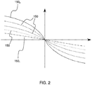
- the figure 2 represents an example of curves 150 of temporal evolution of the frequency shift undergone by the signals received by the object connected 110 from satellite 120, depending on the position of the satellite relative to the connected object.
- the figure 2 comprises five curves, each of which corresponds to a different maximum elevation angle of the satellite 120 seen by the connected object 110.
- the term maximum elevation angle also called by the English term of “ cross-track angle ”, is understood to mean the angle between the ground and the direction of the satellite 120, measured at the level of the object when the satellite 120 is as close as possible to the connected object 110.
- the abscissa of the curves 150 corresponds in the present example to the difference between the latitude of the satellite 110 and the latitude of the connected object 110.
- the satellite 120 When the maximum elevation angle is low, as in the case of the curve 150 1 , the satellite 120 is seen by the connected object 110 as being close to l 'horizon, while when the maximum angle of elevation is of the order of ninety degrees, as in the case of curve 150 2 , the connected object 110 is located substantially in line with the trajectory of satellite 120.
- the figure 3 represents in the form of a block diagram a method 200 for transmitting a signal between one of the connected objects 110 and the satellite 120 moving in orbit.
- the method 200 comprises a step 210 of reception by the connected object 110 of the presence signal transmitted by the satellite 120.
- the presence signal comprises a carrier of frequency f c_sat and at least one modulated subcarrier having a predetermined frequency deviation f S with respect to the frequency f c_sat in order to be able to differentiate the signals originating from the signals.
- beacons signals originating from connected objects 110, which do not have this particular shape or which otherwise have a predetermined frequency difference different from the frequency difference f S of the presence signal.
- the presence signal of the satellite 120 comprises information making it possible to identify the origin of the presence signal, that is to say in the present case of the beacon 125 of the satellite 120, via the presence of the modulated subcarrier exhibiting a predetermined frequency deviation f S with respect to the frequency f c_sat .
- the information identifying the presence signal can be coded in the presence signal emitted by the beacon 125 by any technique known to those skilled in the art.
- such a presence signal comprising a carrier and at least one subcarrier is of the self-synchronous type.
- the frequency shift varies over time because the angles ⁇ , E and ⁇ vary as a function of the displacement of the satellite 120 relative to the connected object 110.
- the recognition of presence signals thanks to the presence of a subcarrier exhibiting a predetermined frequency deviation with respect to the carrier is advantageously used in the case of a telecommunications network, called a hydride, comprising a plurality of connected objects and a plurality of satellites, in which a connected object can receive signals from both a satellite and another connected object.
- a telecommunications network called a hydride
- Step 210 comprises for example a sub-step 211 for detecting the signal from the beacon 125 from among a plurality of signals received.
- the super-feedback receiver included in the connected object 110 makes it possible to detect the presence signal emitted by the beacon 125 thanks to the presence of the sub-carrier in the presence signal, the frequency deviation of which from the carrier frequency of the presence signal is advantageously predetermined.
- the super-reaction receiver advantageously has very low energy consumption of the order of one hundred microwatts in active reception. Power consumption of the super-responsive receiver can be reduced by performing recurrent, non-contiguous detections through detection cycles. The increase in the latency between two consecutive detections makes it possible in particular to reduce the consumption of this receiver.
- the super-feedback receiver is advantageously insensitive to variations in frequency if the carrier and the sub-carriers vary in a similar manner, as is the case when the presence signal is subjected to the Doppler effect.
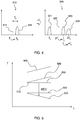
- FIG 4 An example of the result obtained by this detection mechanism is illustrated in figure 4 which comprises a curve 310 before detection and a curve 320 after detection.
- the curve 310 comprises a carrier 311 of frequency f ' c_sat and a modulated subcarrier 312 of frequency f 2 .
- the frequency difference between the carrier and the sub-carrier is equal to f S.
- the detection makes it possible to extract a signal 321 of frequency f S , a signal 322 of frequency 2f ' c_sat , a signal 323 of frequency f' c_sat + f 2 and a signal 324 of frequency 2f 2 .
- An analysis of at least one frequency shift induced by the Doppler effect on the presence signal received by the connected object 110 is carried out during a step 220 of the method 200.
- This measurement is for example carried out via the phase-locked loop included in the connected object 110 by measuring the main frequency of the presence signal received by the connected object 110 at at least two distinct instants, preferably at each instant of reception of the presence signal.
- the temporal evolution of the frequency shift ⁇ f is in fact equal to the temporal variation of the main frequency of the presence signal received.
- an estimate of a subsequent time change in the frequency shift is performed during a step 230 of the method 200.
- This subsequent time change in the frequency shift is calculated in particular in order to predict the frequency shift undergone by the signal to be transmitted by the connected object 110 during its transmission to the satellite 120.
- the subsequent temporal evolution of the frequency shift is thus estimated from a predetermined later instant. the start of transmission of the signal to be transmitted by the device 110, called the transmission time, and over a predetermined duration of this signal to be transmitted. This predetermined duration corresponds in particular to the duration of transmission of the signal.
- the subsequent temporal evolution of the shift is estimated by extrapolation of the temporal evolution of the frequency shift previously measured during step 220.
- the temporal evolution of the previously measured frequency shift can be represented by the intermediary of the theoretical curve ⁇ f (t) whose parameters are adjusted for example via curve regression methods, also called curve fitting methods (in English “Curve fitting ").
- a precompensation of the subsequent time evolution on the presence signal is performed during a step 240 of the method 200.
- the step of precompensating 240 for the subsequent change in time of the frequency shift comprises a modulation of the signal to be transmitted with a frequency opposite to the subsequent change in time.
- the precompensation can be carried out for example by means of an FM modulation (acronym for “ Frequency Modulation ”) whose modulated frequency is equal to the opposite of the variation to be precompensated.
- this FM modulation is applied over a conventional modulation for encoding the binary data contained in the signal transmitted by the connected object 110.
- the conventional modulation for encoding binary data is, in the present non-limiting example of the invention, a modulation of the DBPSK type (acronym for “ Digital Binary Phase-Shift Keying ”) comprising a rate of 100 bits per second.
- the precompensated signal is then emitted, from the time of transmission, during a step 250 of the method 200.
- the precompensation makes it possible in particular to obtain, at the time of reception by the satellite 120 of the signal emitted by the connected object 110, that the reception frequency of the signal carrier by the satellite 120 is substantially constant throughout. along the reception.
- the satellite 120 can consequently process the received signal without needing to apply to it a complex processing for correcting the temporal drift of the frequency due to the Doppler effect. It is thus possible to reuse the algorithms developed for communication between stationary objects. The computing power of the satellite is then used only to demodulate signals which apparently have not undergone a Doppler effect.
- the frequency of the carrier of the signal received by the satellite 120 is certainly constant but is generally different from the frequency of the carrier of the signal at the time of its transmission by the connected object 110.
- the analysis step further comprises a measurement of a main frequency of the presence signal and an estimate of a frequency shift induced by Doppler effect on the presence signal in function of the main frequency measured and as a function of a theoretical main frequency of the heartbeat signal.
- the theoretical frequency of the presence signal which corresponds to the frequency of the carrier when the presence signal is transmitted by the beacon 125, is in certain cases known in advance, in which case the beacon 125 transmits on a predetermined frequency corresponding for example to a previously established standard.
- the transmission frequency of the carrier is a priori unknown, the value of said transmission frequency can for example be encoded in the presence signal, and for example modulate the modulated subcarrier of said presence signal.
- the measurement of the main frequency can be carried out in particular thanks to the phase locked loop included in the connected object 110.
- the method 200 can also include a step 235 of estimating, as a function of the frequency shift estimated on the presence signal, of a frequency shift induced by the Doppler effect at the time of transmission of the signal to be transmitted, called shift subsequent frequency.
- a precompensation of the subsequent frequency shift can also be performed on the signal to be transmitted by the connected object 110, during a step 245 of the method 200, before or after the precompensation of the subsequent estimated time change of the frequency shift.
- the reception frequency of the signal carrier by the satellite 120 is substantially equal to the transmission frequency of the said signal carrier by the connected object 110, with the two precompensations by the connected object 110.
- the figure 5 illustrates the temporal evolution of the transmission frequency of a carrier of a signal 510 emitted by the connected object 110 without precompensation of the Doppler effect, of the same signal 520 transmitted with precompensation of the temporal evolution of the frequency shift and the same signal 525 transmitted with also the optional precompensation of the frequency shift.
- the transmission frequency of the carrier of the signal 510 without precompensation is constant during the transmission of the signal 510.
- the frequency of reception of the carrier of the signal 510 by the satellite 120 is shown on the diagram. figure 5 by the signal 530.
- the difference between the signal 510 and the signal 530 corresponds to the frequency shift induced by the Doppler effect on the frequency of the carrier of the signal 510 during its transmission.
- this frequency shift being a function of the speed and the relative position of the satellite 120 with respect to the connected object 110 changes over time.
- a precompensation of the temporal evolution of the frequency shift is carried out on the signal 510.
- the result obtained by this precompensation is the signal 520 which is seen by the satellite 120 at the time. of its reception as a signal 540 having a reception frequency of the constant carrier but generally different from the transmission frequency of the carrier of the signal 510.
- a pre-compensation of the frequency offset can be applied to the signal 520, so that the transmission frequency of the signal carrier corresponds to that illustrated by the signal 525.
- the signal 525 is transmitted by the connected object 110, it is received by the satellite as a signal 550 whose frequency of reception of the carrier by said satellite 120 is constant and identical to the transmission frequency of the carrier of the signal 510.
- the method 200 can also include a step of identifying the signals intended for the satellite 120 from among a plurality of signals received by the satellite 120. Since the signals intended for the satellite 120 are precompensated, they are easy to identify because they do not require prior treatment to correct the Doppler effect. This step is particularly useful in the case of a hybrid telecommunications system.
Landscapes
- Engineering & Computer Science (AREA)
- Computer Networks & Wireless Communication (AREA)
- Signal Processing (AREA)
- Physics & Mathematics (AREA)
- Astronomy & Astrophysics (AREA)
- Aviation & Aerospace Engineering (AREA)
- General Physics & Mathematics (AREA)
- Radio Relay Systems (AREA)
- Position Fixing By Use Of Radio Waves (AREA)
- Mobile Radio Communication Systems (AREA)
Description
La présente invention appartient au domaine des systèmes de télécommunication sans fil et concerne plus particulièrement un procédé de transmission d'un signal entre au moins un dispositif émetteur et au moins un satellite se déplaçant en orbite.The present invention belongs to the field of wireless telecommunications systems and relates more particularly to a method of transmitting a signal between at least one transmitter device and at least one satellite moving in orbit.
L'invention trouve notamment une application dans le domaine des objets connectés.The invention notably finds an application in the field of connected objects.
La présente invention trouve une application particulièrement avantageuse, bien que nullement limitative, dans les systèmes de télécommunication sans fil à bande ultra étroite. Par « bande ultra étroite » (« Ultra Narrow Band » ou UNB dans la littérature anglo-saxonne), on entend que le spectre fréquentiel instantané des signaux radioélectriques émis par un dispositif émetteur, à destination d'un satellite, est de largeur fréquentielle inférieure à deux kilohertz, voire inférieure à un kilohertz.The present invention finds a particularly advantageous application, although in no way limiting, in ultra-narrow band wireless telecommunications systems. By “ultra narrow band” (“ Ultra Narrow Band ” or UNB in English literature) is meant that the instantaneous frequency spectrum of the radio signals transmitted by a transmitting device, intended for a satellite, is of lower frequency width at two kilohertz, or even less than one kilohertz.
De tels systèmes de télécommunication sans fil UNB sont particulièrement adaptés pour des applications du type M2M (acronyme anglo-saxon pour « Machine-to-Machine ») ou du type « Internet des objets » (« Internet of Things » ou IoT dans la littérature anglo-saxonne).Such UNB wireless telecommunication systems are particularly suitable for applications of the M2M type (acronym for “ Machine-to-Machine ”) or of the “Internet of Things” type (“ Internet of Things ” or IoT in the literature. Anglo-Saxon).
Un des inconvénients majeurs des systèmes de télécommunication sans fil comprenant un dispositif émetteur et un satellite non géosynchrone est l'apparition de l'effet Doppler venant perturber la transmission des signaux entre le dispositif émetteur et le satellite. L'effet Doppler, fonction de la vitesse de l'objet en mouvement et de l'angle entre le vecteur vitesse de l'objet en mouvement et la direction entre les deux objets, modifie à chaque instant la fréquence des signaux transmis. Ainsi, pour la réception d'un signal ayant été émis sur une fréquence d'émission constante au cours du temps, la fréquence de réception du signal au début de la réception est différente de la fréquence de réception du signal à la fin de la réception. La variation de la fréquence de réception au cours du temps peut en outre être importante du fait, pour des applications de type M2M ou IoT, le débit de données est généralement faible de sorte que la durée du signal peut être importante. Cette évolution de la fréquence de réception au cours du temps rend la détection de tels signaux complexe au niveau du satellite.One of the major drawbacks of wireless telecommunication systems comprising a transmitter device and a non-geosynchronous satellite is the appearance of the Doppler effect which disturbs the transmission of signals between the transmitter device and the satellite. The Doppler effect, which is a function of the speed of the moving object and of the angle between the speed vector of the moving object and the direction between the two objects, changes the frequency of the transmitted signals at each instant. Thus, for the reception of a signal having been transmitted on a constant transmission frequency over time, the reception frequency of the signal at the start of reception is different from the reception frequency of the signal at the end of reception. . The variation in the frequency of reception over time can also be important because, for M2M or IoT type applications, the data rate is generally low so that the duration of the signal can be long. This change in the reception frequency over time makes the detection of such signals complex at the satellite level.
Un autre inconvénient induit par l'apparition de l'effet Doppler sur les signaux est la diminution de la capacité du canal de communication pour une même largeur de bande. Par ailleurs, l'effet Doppler implique également l'augmentation du nombre de collisions entre signaux. Un exemple d'état de la technique est décrit par
La présente invention a pour objectif de remédier à tout ou partie des limitations des solutions de l'art antérieur, notamment celles exposées ci-avant, en proposant une solution permettant à un satellite d'un système de télécommunication de détecter plus facilement des signaux émis par des dispositifs émetteurs et/ou de réduire les collisions entre signaux émis par de tels dispositifs émetteurs.The object of the present invention is to remedy all or part of the limitations of the solutions of the prior art, in particular those described above, by proposing a solution allowing a satellite of a telecommunications system to more easily detect signals transmitted. by transmitting devices and / or reducing collisions between signals transmitted by such transmitting devices.
A cet effet, et selon un premier aspect, l'invention concerne un procédé de transmission d'un signal par un dispositif émetteur vers un satellite se déplaçant en orbite autour de la Terre, ledit dispositif émetteur et le satellite comprenant des moyens de télécommunication sans fil.To this end, and according to a first aspect, the invention relates to a method of transmitting a signal by a transmitter device to a satellite moving in orbit around the Earth, said transmitter device and the satellite comprising wireless telecommunication means. wire.
On entend par dispositif émetteur tout objet muni d'un moyen de télécommunication apte à émettre un signal. Le dispositif émetteur peut être par exemple un objet connecté. On entend par objet connecté, tout appareil connecté à un réseau informatique d'échanges de données de type Internet, interrogeable ou contrôlable à distance. L'objet connecté est de type quelconque. Il peut être par exemple une station météo collectant les données de températures intérieure et extérieure d'une habitation, un capteur de mesure du niveau de liquide ou de gaz dans une citerne ou une cuve, un détecteur d'occupation d'une place de parking, un capteur de mesure du flux de personnes accédant à un bâtiment, etc. L'objet connecté peut également être une base de relais entre un appareil connecté et un réseau. Cette base de relais peut faire office de répétiteur ou de tampon en stockant des données à transmettre au réseau dans une mémoire informatique de la base de relais.The term “transmitter device” is understood to mean any object provided with a means of telecommunication capable of transmitting a signal. The sending device can be for example a connected object. “Connected object” is understood to mean any device connected to an Internet-type data exchange computer network, which can be interrogated or controlled remotely. The connected object is of any type. It can be for example a weather station collecting indoor and outdoor temperature data of a home, a sensor for measuring the level of liquid or gas in a cistern or a tank, a detector of occupancy of a parking space. , a sensor for measuring the flow of people entering a building, etc. The connected object can also be a relay base between a connected device and a network. This relay base can act as a repeater or a buffer by storing data at transmit to the network in a computer memory of the relay base.
Selon l'invention, ledit procédé comprend des étapes de :
- réception par ledit dispositif émetteur d'un signal émis par le satellite, dit signal de présence ;
- analyse d'au moins un décalage fréquentiel induit par effet Doppler sur le signal de présence reçu par ledit dispositif émetteur, l'étape d'analyse comportant une mesure d'une évolution temporelle du décalage fréquentiel induit par effet Doppler sur le signal de présence ;
- estimation, en fonction de l'analyse du décalage fréquentiel induit par effet Doppler sur le signal de présence, d'une évolution temporelle ultérieure dudit décalage fréquentiel à partir d'un instant ultérieur prédéterminé de début d'émission du signal à émettre par le dispositif émetteur, dit instant d'émission, et sur une durée prédéterminée dudit signal à émettre ;
- précompensation de l'évolution temporelle ultérieure estimée du décalage fréquentiel sur le signal à émettre ;
- émission du signal par ledit dispositif émetteur à partir de l'instant d'émission.
- reception by said transmitter device of a signal transmitted by the satellite, called a presence signal;
- analysis of at least one frequency shift induced by the Doppler effect on the presence signal received by said transmitter device, the analysis step comprising a measurement of a temporal evolution of the frequency shift induced by Doppler effect on the presence signal;
- estimation, as a function of the analysis of the frequency shift induced by the Doppler effect on the presence signal, of a subsequent change in time of said frequency shift from a predetermined later instant of start of transmission of the signal to be transmitted by the device transmitter, said time of transmission, and over a predetermined duration of said signal to be transmitted;
- precompensation of the estimated subsequent temporal evolution of the frequency shift on the signal to be transmitted;
- transmission of the signal by said emitting device from the instant of transmission.
Ainsi, le signal émis par le dispositif émetteur pouvant être précompensé durant la majeure partie de son émission, voire préférentiellement à chaque instant de son émission, est reçu par le satellite sans effet Doppler apparent. En d'autres termes, en prenant l'exemple d'un signal comprenant une porteuse de fréquence constante avant précompensation, le signal est précompensé avant ou au moment de l'émission afin que la fréquence de réception de la porteuse du signal reçu par le satellite soit constante.Thus, the signal emitted by the transmitter device which can be precompensated during the major part of its transmission, or even preferably at each instant of its transmission, is received by the satellite without apparent Doppler effect. In other words, taking the example of a signal comprising a carrier of constant frequency before precompensation, the signal is precompensated before or at the time of transmission so that the reception frequency of the carrier of the signal received by the satellite is constant.
Au cours de l'étape d'analyse, l'évolution temporelle du décalage fréquentiel induit par effet Doppler peut être mesurée en mesurant la variation temporelle d'une fréquence principale du signal de présence. La fréquence principale du signal de présence est représentative par exemple de la fréquence d'une porteuse dudit signal de présence, ou encore de la fréquence d'une sous-porteuse dudit signal de présence, d'une fréquence centrale d'un spectre fréquentiel instantané dudit signal de présence, d'une fréquence minimale ou maximale dudit spectre fréquentiel instantané, etc. La variation temporelle de la fréquence principale du signal de présence reçu est en principe similaire à la variation temporelle du décalage fréquentiel, notamment lorsque le signal de présence est émis avec une fréquence principale constante au cours du temps. La variation temporelle de la fréquence principale peut être mesurée directement en mesurant la différence entre la fréquence principale à deux instants respectifs différents ou indirectement en mesurant la fréquence principale en au moins deux instants respectifs différents, et en calculant la différence entre les fréquences principales mesurées.During the analysis step, the time variation of the frequency shift induced by the Doppler effect can be measured by measuring the time variation of a main frequency of the heartbeat. The main frequency of the presence signal is representative for example of the frequency of a carrier of said presence signal, or else of the frequency a subcarrier of said presence signal, a central frequency of an instantaneous frequency spectrum of said presence signal, a minimum or maximum frequency of said instantaneous frequency spectrum, and so on. The temporal variation of the main frequency of the presence signal received is in principle similar to the temporal variation of the frequency shift, in particular when the presence signal is transmitted with a main frequency constant over time. The time variation of the main frequency can be measured directly by measuring the difference between the main frequency at two different respective times or indirectly by measuring the main frequency at at least two different respective times, and calculating the difference between the measured main frequencies.
Par ailleurs, l'analyse du signal précompensé reçu par le satellite est plus aisée à effectuer, car elle ne nécessite pas un traitement spécifique du signal reçu afin de pallier l'effet Doppler, réduisant de facto le nombre de calculs nécessaires pour détecter et éventuellement démoduler le signal reçu.Furthermore, the analysis of the precompensated signal received by the satellite is easier to perform, since it does not require specific processing of the received signal in order to overcome the Doppler effect, de facto reducing the number of calculations required to detect and possibly demodulate the received signal.
D'autre part, compte-tenu que la variation temporelle du décalage fréquentiel induit par effet Doppler n'est plus apparente, des algorithmes et des programmes informatiques adaptés à des objets immobiles peuvent être réutilisés sans nécessiter d'adaptation particulière.On the other hand, given that the temporal variation of the frequency shift induced by the Doppler effect is no longer apparent, algorithms and computer programs adapted to stationary objects can be reused without requiring special adaptation.
Il convient de souligner que seule la variation temporelle du décalage fréquentiel, ou dérive temporelle de la fréquence, due à l'effet Doppler, est corrigée. En effet, la précompensation prend en compte seulement l'évolution temporelle du décalage fréquentiel et non la valeur absolue du décalage fréquentiel. En d'autres termes, la fréquence de réception de la porteuse du signal reçu est sensiblement constante si la porteuse avant précompensation est de fréquence constante, mais peut néanmoins être décalée par rapport à la fréquence théorique de ladite porteuse dudit signal du fait du décalage fréquentiel induit par Effet Doppler. Ainsi, la précompensation vise à obtenir un décalage fréquentiel induit par effet Doppler perçu au niveau du satellite comme étant invariant au cours du temps.It should be emphasized that only the temporal variation of the frequency shift, or temporal drift of the frequency, due to the Doppler effect, is corrected. Indeed, the precompensation takes into account only the temporal evolution of the frequency shift and not the absolute value of the frequency shift. In other words, the reception frequency of the carrier of the signal received is substantially constant if the carrier before precompensation is of constant frequency, but can nevertheless be offset with respect to the theoretical frequency of said carrier of said signal due to the frequency offset induced by Doppler Effect. Thus, the precompensation aims to obtain a frequency shift induced by the Doppler effect perceived at the satellite level as being invariant over time.
Dans des modes particuliers de mise en œuvre, le procédé de transmission peut comporter en outre l'une ou plusieurs des caractéristiques suivantes, prises isolément ou selon toutes les combinaisons techniquement possibles.In particular modes of implementation, the method of transmission may also include one or more of the following characteristics, taken in isolation or in any technically possible combination.
Dans des modes particuliers de mise en œuvre, l'étape de précompensation de l'évolution temporelle ultérieure du décalage fréquentiel comprend une modulation du signal à émettre avec une fréquence opposée à l'évolution temporelle ultérieure.In particular embodiments, the step of precompensating the subsequent temporal evolution of the frequency shift comprises a modulation of the signal to be transmitted with a frequency opposite to the subsequent temporal evolution.
Dans des modes particuliers de mise en œuvre, l'évolution temporelle ultérieure du décalage fréquentiel est estimée par extrapolation de l'évolution temporelle du décalage fréquentiel mesurée sur le signal de présence.In particular embodiments, the subsequent change in time of the frequency shift is estimated by extrapolation of the time change in the frequency shift measured on the presence signal.
Dans des modes particuliers de mise en œuvre, l'évolution temporelle mesurée du décalage fréquentiel est représentée par une courbe dont les paramètres sont calculés par une méthode d'ajustement de courbe.In particular embodiments, the measured change over time of the frequency shift is represented by a curve whose parameters are calculated by a curve fitting method.
Les méthodes d'ajustement de courbe (en anglais « curve fitting ») sont également connues sous le nom de méthodes de régression.The curve fitting methods are also known under the name of regression methods.
Dans des modes particuliers de mise en œuvre, l'étape d'analyse comporte une mesure d'une fréquence principale du signal de présence et une estimation d'un décalage fréquentiel induit par effet Doppler sur le signal de présence en fonction de la fréquence principale mesurée et en fonction d'une fréquence principale théorique dudit signal de présence, ledit procédé comportant également des étapes de :
- estimation, en fonction du décalage fréquentiel estimé sur le signal de présence, d'un décalage fréquentiel ultérieur induit par effet Doppler à l'instant d'émission du signal à émettre,
- précompensation du décalage fréquentiel ultérieur sur le signal à émettre.
- estimation, as a function of the frequency shift estimated on the presence signal, of a subsequent frequency shift induced by the Doppler effect at the time of transmission of the signal to be transmitted,
- precompensation of the subsequent frequency shift on the signal to be transmitted.
Dans de tels modes de mise en œuvre, la précompensation vise donc à annuler non seulement la variation temporelle du décalage fréquentiel induit par effet Doppler au niveau du satellite, mais également à annuler la valeur absolue dudit décalage fréquentiel au niveau dudit satellite. Ainsi, la précompensation permet d'obtenir en outre que la fréquence de la porteuse du signal reçu par le satellite est sensiblement égale à la fréquence théorique de la porteuse du signal émis par le dispositif émetteur.In such embodiments, the precompensation therefore aims to cancel not only the temporal variation of the frequency shift induced by the Doppler effect at the level of the satellite, but also to cancel the absolute value of said frequency shift at the level of said satellite. Thus, the precompensation also makes it possible to obtain that the frequency of the carrier of the signal received by the satellite is substantially equal to the theoretical frequency of the carrier of the signal emitted by the sending device.
Dans des modes particuliers de mise en œuvre, l'étape d'analyse met en œuvre une boucle à verrouillage de phase.In particular embodiments, the analysis step implements a phase locked loop.
Dans des modes particuliers de mise en œuvre, l'émission du signal de présence est effectuée en continu sur une période prédéterminée.In particular modes of implementation, the transmission of the presence signal is carried out continuously over a predetermined period.
Selon un deuxième aspect, la présente invention concerne un dispositif émetteur d'un système de télécommunication sans fil, mettant en œuvre un procédé de transmission selon l'un quelconque des modes de mise en œuvre de l'invention.According to a second aspect, the present invention relates to a transmitter device of a wireless telecommunications system, implementing a transmission method according to any one of the embodiments of the invention.
Dans des modes particuliers de réalisation, le dispositif émetteur est un objet connecté.In particular embodiments, the sending device is a connected object.
Selon un troisième aspect, la présente invention concerne un système de télécommunication sans fil comprenant au moins un dispositif émetteur selon l'un quelconque des modes de réalisation de l'invention et au moins un satellite se déplaçant en orbite autour de la Terre.According to a third aspect, the present invention relates to a wireless telecommunications system comprising at least one transmitter device according to any one of the embodiments of the invention and at least one satellite moving in orbit around the Earth.
L'invention sera mieux comprise à la lecture de la description suivante, donnée à titre d'exemple nullement limitatif, et faite en se référant aux figures qui représentent :
-
Figure 1 : une représentation schématique d'un exemple de réalisation d'un système de télécommunication, -
Figure 2 : des courbes illustrant les variations du décalage fréquentiel en fonction de la position d'un satellite relativement à un dispositif émetteur du système de télécommunication de lafigure 1 , -
Figure 3 : un diagramme illustrant un exemple de mise en œuvre d'un procédé de transmission d'un signal par un dispositif émetteur vers un satellite, -
Figure 4 : deux courbes illustrant un traitement effectué pour la détection d'un signal de présence émis par le satellite, -
Figure 5 : des courbes illustrant les différents traitements effectués sur un signal émis par un dispositif émetteur du système de télécommunication.
-
Figure 1 : a schematic representation of an exemplary embodiment of a telecommunications system, -
Figure 2 : curves illustrating the variations of the frequency shift as a function of the position of a satellite relative to a transmitting device of the telecommunications system of thefigure 1 , -
Figure 3 : a diagram illustrating an example of implementation of a method of transmitting a signal by a transmitting device to a satellite, -
Figure 4 : two curves illustrating a processing carried out for the detection of a presence signal transmitted by the satellite, -
Figure 5 : curves illustrating the different processing carried out on a signal transmitted by a transmitter device of the telecommunications system.
Dans ces figures, des références identiques d'une figure à une autre désignent des éléments identiques ou analogues. Pour des raisons de clarté, les éléments représentés ne sont pas à l'échelle, sauf mention contraire.In these figures, identical references from one figure to another designate identical or similar elements. For reasons of clarity, the elements shown are not to scale, unless otherwise indicated.
La
Les dispositifs émetteurs 110 et le satellite 120 échangent des données sous la forme de signaux radioélectriques. Par « signal radioélectrique », on entend une onde électromagnétique se propageant via des moyens non filaires, dont les fréquences sont comprises dans le spectre traditionnel des ondes radioélectriques (quelques hertz à plusieurs centaines de gigahertz).The transmitting
Les dispositifs émetteurs 110 sont dans le présent exemple non limitatif de réalisation de l'invention des objets connectés comprenant des moyens 111 de télécommunication aptes à transmettre des signaux au satellite 120. Il convient de souligner que les dispositifs émetteurs 110, appelés par la suite objets connectés 110, peuvent également, dans des modes particuliers de réalisation, échanger des signaux entre eux.In the present non-limiting example of the embodiment of the invention, the transmitting
Par exemple, les objets connectés 110 comprennent en outre une carte électronique 112 munie d'un microprocesseur apte à traiter des données, voire d'une mémoire informatique apte à stocker des données avant leur transmission par l'intermédiaire de signaux.For example, the
Les signaux transmis par les objets connectés 110, et/ou les signaux transmis par le satellite 120, sont par exemple des signaux à bande ultra étroite (UNB, acronyme anglais de « Ultra Narrow Band »).The signals transmitted by the
Les signaux UNB échangés au sein du système 100 de télécommunication comprennent une porteuse dont la fréquence est par exemple de l'ordre de la centaine de MHz, voire du GHz. La largeur de bande des signaux UNB est inférieure à 2 kHz, voire inférieure à 1 kHz.The UNB signals exchanged within the
Les moyens 111 de télécommunication reliés à la carte électronique 112 dudit objet connecté 110 comprennent dans le présent exemple non limitatif de l'invention une antenne apte à transmettre et recevoir des signaux UNB, une boucle à verrouillage de phase et un récepteur à super réaction.The telecommunications means 111 connected to the
Le satellite 120 est dans le présent exemple, un nanosatellite de type CubeSat formée par une structure cubique de dix centimètres de côté. Deux panneaux photovoltaïques 121 déployés de part et d'autre de la structure cubique alimentent le satellite 120 en énergie. La masse du satellite 120 est sensiblement égale à cinq kilos. Une antenne 122 dirigée vers la surface terrestre permet d'émettre ou de recevoir des signaux UNB à destination ou en provenance des objets connectés 110. Il convient de souligner que le satellite 120 est placé sur une orbite de l'ordre de cinq cents kilomètres autour de la Terre. Le satellite 120 se déplace ainsi autour de la Terre à une vitesse de l'ordre de sept kilomètres par seconde, et effectue un tour complet autour de la planète en une durée de l'ordre de quatre-vingt-dix minutes. De manière plus générale, le satellite 120 est en orbite non-géosynchrone, par exemple en orbite LEO (« Low Earth Orbit ») ou MEO (« Medium Earth Orbit »).The
Le satellite 120 comprend en outre une balise 125, également connue sous le terme anglais de « beacon », émettant un signal UNB en continu, appelé par la suite signal de présence. Le signal de présence émis par la balise 125 comprend par exemple une porteuse dont la fréquence, au moment de l'émission, est par exemple constante au cours du temps.The
Dans une variante de ce mode de réalisation particulier de l'invention, la balise 125 émet des signaux de présence de manière discontinue, préférentiellement à intervalles réguliers. Les signaux de présence émis sont par exemple de durée limitée, par exemple de l'ordre de quelques centaines de millisecondes, de quelques secondes, voire de quelques minutes.In a variant of this particular embodiment of the invention, the
Il convient de souligner que dans un souci d'économie d'énergie, l'objet connecté 110 est généralement, mais non limitativement, en mode veille pendant la plupart du temps et qu'il sort de ce mode veille à intervalles réguliers pour écouter et/ou transmettre des signaux.It should be noted that for the sake of energy saving, the
La
La
Le procédé 200 comprend une étape 210 de réception par l'objet connecté 110 du signal de présence émis par le satellite 120.The
Dans des modes préférés de mise en œuvre, le signal de présence comporte une porteuse de fréquence fc_sat et au moins une sous-porteuse modulée présentant un écart fréquentiel fS prédéterminé par rapport à la fréquence fc_sat afin de pouvoir différencier les signaux provenant des balises, des signaux provenant des objets connectés 110, qui ne présentent pas cette forme particulière ou qui présentent dans le cas contraire un écart fréquentiel prédéterminé différent de l'écart fréquentiel fS du signal de présence.In preferred embodiments, the presence signal comprises a carrier of frequency f c_sat and at least one modulated subcarrier having a predetermined frequency deviation f S with respect to the frequency f c_sat in order to be able to differentiate the signals originating from the signals. beacons, signals originating from
En d'autres termes, le signal de présence du satellite 120 comprend une information permettant d'identifier la provenance du signal de présence, c'est-à-dire dans le cas présent de la balise 125 du satellite 120, par l'intermédiaire de la présence de la sous-porteuse modulée présentant un écart fréquentiel fS prédéterminé par rapport à la fréquence fc_sat. De manière plus générale, l'information d'identification du signal de présence peut être codée dans le signal de présence émis par la balise 125 par toute technique connue de l'homme du métier.In other words, the presence signal of the
Il convient de souligner qu'un tel signal de présence comprenant une porteuse et au moins une sous-porteuse est de type auto-synchrone.It should be emphasized that such a presence signal comprising a carrier and at least one subcarrier is of the self-synchronous type.
Le signal de présence émis par la balise 125 avec une porteuse de fréquence fc_sat est reçu par l'objet connecté 110 avec une porteuse de fréquence f'c_sat = fc_sat+Δf(t) où Δf(t) représente le décalage fréquentiel induit par effet Doppler qui varie au cours de la transmission du signal de présence de la balise 125 du satellite 120 vers l'objet connecté 110. ![]()
- où v représente la norme du vecteur vitesse du satellite,
- fc la porteuse du signal émis, ici égale à fc_sat,
- c la vitesse de la lumière,
- θ l'angle entre le vecteur vitesse du
satellite 120 et le plan définipar le satellite 120,l'objet 110 et le centre de la Terre, - E l'angle d'élévation entre l'horizon et le
satellite 120 au niveau de l'objet 110, ϕ l'angle, également appelé angle de couverture, entre le sub-satellite point, c'est-à-dire le point du satellite projeté sur la surface terrestre et l'objet 110.
- where v represents the norm of the satellite speed vector,
- f c the carrier of the transmitted signal, here equal to f c_sat ,
- c the speed of light,
- θ the angle between the speed vector of the
satellite 120 and the plane defined by thesatellite 120, theobject 110 and the center of the Earth, - E the angle of elevation between the horizon and the
satellite 120 at the level of theobject 110, ϕ the angle, also called the coverage angle, between the sub-satellite point, that is to say the point of the satellite projected onto the earth's surface andobject 110.
Il convient de souligner que le décalage fréquentiel varie au cours du temps car les angles θ, E et ϕ varient en fonction du déplacement du satellite 120 par rapport à l'objet connecté 110.It should be noted that the frequency shift varies over time because the angles θ , E and ϕ vary as a function of the displacement of the
La reconnaissance des signaux de présence grâce à la présence d'une sous-porteuse présentant un écart fréquentiel prédéterminé par rapport à la porteuse est avantageusement utilisée dans le cas d'un réseau de télécommunication, dit hydride, comprenant une pluralité d'objets connectés et une pluralité de satellites, dans lequel un objet connecté peut recevoir des signaux provenant à la fois d'un satellite et d'un autre objet connecté.The recognition of presence signals thanks to the presence of a subcarrier exhibiting a predetermined frequency deviation with respect to the carrier is advantageously used in the case of a telecommunications network, called a hydride, comprising a plurality of connected objects and a plurality of satellites, in which a connected object can receive signals from both a satellite and another connected object.
L'étape 210 comprend par exemple une sous-étape 211 de détection du signal de la balise 125 parmi une pluralité de signaux reçus. A cet effet, le récepteur à super réaction inclus dans l'objet connecté 110 permet de détecter le signal de présence émis par la balise 125 grâce à la présence de la sous-porteuse dans le signal de présence, dont l'écart fréquentiel par rapport à la fréquence porteuse du signal de présence est avantageusement prédéterminé. Il convient de souligner que le récepteur à super réaction a avantageusement une très faible consommation énergétique de l'ordre de cent microwatts en réception active. La consommation du récepteur à super réaction peut être réduite en effectuant des détections récurrentes, non contigües, par l'intermédiaire de cycles de détection. L'augmentation de la latence entre deux détections consécutives permet notamment de réduire la consommation de ce récepteur.Step 210 comprises for example a sub-step 211 for detecting the signal from the
Par ailleurs, il convient de souligner que le récepteur à super réaction est avantageusement insensible aux variations en fréquence si la porteuse et les sous-porteuses varient de manière semblable, comme c'est le cas lorsque le signal de présence subit l'effet Doppler.Furthermore, it should be emphasized that the super-feedback receiver is advantageously insensitive to variations in frequency if the carrier and the sub-carriers vary in a similar manner, as is the case when the presence signal is subjected to the Doppler effect.
Un exemple de résultat obtenu par ce mécanisme de détection est illustré en
Une analyse d'au moins un décalage fréquentiel induit par effet Doppler sur le signal de présence reçu par l'objet connecté 110 est effectuée au cours d'une étape 220 du procédé 200.An analysis of at least one frequency shift induced by the Doppler effect on the presence signal received by the
Lors de cette étape d'analyse 220, une mesure d'une évolution temporelle du décalage fréquentiel Δf induit par effet Doppler sur le signal de présence reçu par l'objet connecté 110 est effectuée.During this
Cette mesure est par exemple réalisée par l'intermédiaire de la boucle à verrouillage de phase incluse dans l'objet connecté 110 en mesurant la fréquence principale du signal de présence reçu par l'objet connecté 110 à au moins deux instants distincts, préférentiellement à chaque instant de la réception du signal de présence. L'évolution temporelle du décalage fréquentiel Δf est en effet égale à la variation temporelle de la fréquence principale du signal de présence reçu.This measurement is for example carried out via the phase-locked loop included in the
A partir de l'analyse du décalage fréquentiel induit par effet Doppler sur le signal de présence, une estimation d'une évolution temporelle ultérieure du décalage fréquentiel est effectuée au cours d'une étape 230 du procédé 200. Cette évolution temporelle ultérieure du décalage fréquentiel est notamment calculée afin de prédire le décalage fréquentiel subi par le signal à émettre par l'objet connecté 110 lors de sa transmission à destination du satellite 120. L'évolution temporelle ultérieure du décalage fréquentiel est ainsi estimée à partir d'un instant ultérieur prédéterminé de début d'émission du signal à émettre par le dispositif 110, dit instant d'émission, et sur une durée prédéterminée de ce signal à émettre. Cette durée prédéterminée correspond notamment à la durée d'émission du signal.From the analysis of the frequency shift induced by the Doppler effect on the heartbeat, an estimate of a subsequent time change in the frequency shift is performed during a
Dans des modes préférés de l'invention, l'évolution temporelle ultérieure du décalage est estimée par extrapolation de l'évolution temporelle du décalage fréquentiel préalablement mesurée au cours de l'étape 220.In preferred embodiments of the invention, the subsequent temporal evolution of the shift is estimated by extrapolation of the temporal evolution of the frequency shift previously measured during
L'évolution temporelle du décalage fréquentiel préalablement mesurée peut être représentée par l'intermédiaire de la courbe théorique Δf(t) dont les paramètres sont ajustés par exemple via des méthodes de régression de courbes, également appelées méthodes d'ajustement de courbes (en anglais « curve fitting »).The temporal evolution of the previously measured frequency shift can be represented by the intermediary of the theoretical curve Δf (t) whose parameters are adjusted for example via curve regression methods, also called curve fitting methods (in English "Curve fitting ").
L'estimation de l'évolution temporelle ultérieure du décalage fréquentiel peut être effectuée à partir de cette courbe théorique, dont les paramètres ont été ajustés.The estimation of the subsequent temporal evolution of the frequency shift can be made from this theoretical curve, the parameters of which have been adjusted.
Une fois que l'évolution temporelle ultérieure est estimée, une précompensation de l'évolution temporelle ultérieure sur le signal de présence est effectuée au cours d'une étape 240 du procédé 200.Once the subsequent time evolution is estimated, a precompensation of the subsequent time evolution on the presence signal is performed during a
Dans des modes préférentiels de mise en œuvre de l'invention, l'étape de précompensation 240 de l'évolution temporelle ultérieure du décalage fréquentiel comprend une modulation du signal à émettre avec une fréquence opposée à l'évolution temporelle ultérieure. La précompensation peut s'effectuer par exemple par l'intermédiaire d'une modulation FM (acronyme anglais de « Frequency Modulation ») dont la fréquence modulée est égale à l'opposée de la variation à précompenser.In preferred embodiments of the invention, the step of precompensating 240 for the subsequent change in time of the frequency shift comprises a modulation of the signal to be transmitted with a frequency opposite to the subsequent change in time. The precompensation can be carried out for example by means of an FM modulation (acronym for “ Frequency Modulation ”) whose modulated frequency is equal to the opposite of the variation to be precompensated.
Il convient de souligner que cette modulation FM est appliquée pardessus une modulation classique d'encodage des données binaires contenues dans le signal émis par l'objet connecté 110. La modulation classique d'encodage des données binaires est, dans le présent exemple non limitatif de l'invention, une modulation du type DBPSK (acronyme anglais de « Digital Binary Phase-Shift Keying ») comprenant un débit de 100 bits par secondes.It should be emphasized that this FM modulation is applied over a conventional modulation for encoding the binary data contained in the signal transmitted by the
Le signal précompensé est ensuite émis, à partir de l'instant d'émission, au cours d'une étape 250 du procédé 200.The precompensated signal is then emitted, from the time of transmission, during a
Il convient de souligner que la précompensation permet notamment d'obtenir au moment de la réception par le satellite 120 du signal émis par l'objet connecté 110, que la fréquence de réception de la porteuse du signal par le satellite 120 est sensiblement constante tout le long de la réception.It should be emphasized that the precompensation makes it possible in particular to obtain, at the time of reception by the
Le satellite 120 peut par conséquent traiter le signal reçu sans avoir besoin de lui appliquer un traitement complexe de correction de la dérive temporelle de la fréquence due à l'effet Doppler. Il est ainsi possible de réutiliser les algorithmes développés pour la communication entre des objets immobiles. La puissance de calcul du satellite n'est alors utilisée que pour démoduler des signaux n'ayant apparemment pas subi d'effet Doppler.The
Par ailleurs, il convient de souligner que la précompensation proposée dans le présent exemple ne tient pas compte de la valeur absolue du décalage fréquentiel. La fréquence de la porteuse du signal reçu par le satellite 120 est certes constante mais est généralement différente de la fréquence de la porteuse du signal au moment de son émission par l'objet connecté 110.Furthermore, it should be emphasized that the precompensation proposed in the present example does not take into account the absolute value of the frequency shift. The frequency of the carrier of the signal received by the
A cet effet, il peut être prévu de manière optionnelle que l'étape d'analyse comporte en outre une mesure d'une fréquence principale du signal de présence et une estimation d'un décalage fréquentiel induit par effet Doppler sur le signal de présence en fonction de la fréquence principale mesurée et en fonction d'une fréquence principale théorique du signal de présence. La fréquence théorique du signal de présence, qui correspond à la fréquence de la porteuse au moment de l'émission du signal de présence par la balise 125, est dans certains cas connue à l'avance, auquel cas la balise 125 émet sur une fréquence prédéterminée correspondant par exemple à un standard préalablement établi. Lorsque la fréquence d'émission de la porteuse est a priori inconnue, la valeur de ladite fréquence d'émission peut être par exemple codée dans le signal de présence, et module par exemple la sous-porteuse modulée dudit signal de présence. La mesure de la fréquence principale peut être notamment effectuée grâce à la boucle à verrouillage de phase incluse dans l'objet connecté 110.For this purpose, it can be optionally provided that the analysis step further comprises a measurement of a main frequency of the presence signal and an estimate of a frequency shift induced by Doppler effect on the presence signal in function of the main frequency measured and as a function of a theoretical main frequency of the heartbeat signal. The theoretical frequency of the presence signal, which corresponds to the frequency of the carrier when the presence signal is transmitted by the
Ainsi, le procédé 200 peut comporter également une étape 235 d'estimation, en fonction du décalage fréquentiel estimé sur le signal de présence, d'un décalage fréquentiel induit par effet Doppler à l'instant d'émission du signal à émettre, dit décalage fréquentiel ultérieur. Une précompensation du décalage fréquentiel ultérieur peut également être effectuée sur le signal à émettre par l'objet connecté 110, au cours d'une étape 245 du procédé 200, avant ou après la précompensation de l'évolution temporelle ultérieure estimée du décalage fréquentiel.Thus, the
Dans ce cas, la fréquence de réception de la porteuse du signal par le satellite 120 est sensiblement égale à la fréquence d'émission de la porteuse dudit signal par l'objet connecté 110, avec les deux précompensations par l'objet connecté 110.In this case, the reception frequency of the signal carrier by the
La
La fréquence d'émission de la porteuse du signal 510 sans précompensation est constante au cours de l'émission du signal 510. La fréquence de réception de la porteuse du signal 510 par le satellite 120 est représentée sur la
Afin d'obtenir une fréquence de réception de la porteuse constante mais également identique à la fréquence d'émission de ladite porteuse du signal 510, une précompensation du décalage fréquentiel peut être appliquée au signal 520, de sorte que la fréquence d'émission de la porteuse correspond à celle illustrée par le signal 525. Lorsque le signal 525 est émis par l'objet connecté 110, il est reçu par le satellite comme un signal 550 dont la fréquence de réception de la porteuse par ledit satellite 120 est constante et identique à la fréquence d'émission de la porteuse du signal 510.In order to obtain a reception frequency of the constant carrier but also identical to the transmission frequency of said carrier of the
De manière optionnelle, le procédé 200 peut également comprendre une étape d'identification des signaux destinés au satellite 120 parmi une pluralité de signaux reçus par le satellite 120. Etant donné que les signaux destinés au satellite 120 sont précompensés, ils sont faciles à identifier car ils ne nécessitent pas de traitement préalable de correction de l'effet Doppler. Cette étape est notamment utile dans le cas d'un système de télécommunication hybride.Optionally, the
Claims (9)
- Method (200) for transmitting a signal by a transmitter device (110) to a satellite (120) moving in orbit around the Earth, said transmitter device (110) and the satellite (120) comprising wireless telecommunication means, characterised in that said method comprises the steps of:- receiving (210), by said transmitter device (110), a signal transmitted by the satellite (120), termed the presence signal;- analysing (220) a frequency shift induced by the Doppler effect on the presence signal received by said transmitter device (110), the step of analysing (220) comprising a measurement of a change over time of the frequency shift induced by the Doppler effect on the presence signal;- estimating (230), according to the analysis of the frequency shift induced by the Doppler effect on the presence signal, a later change over time of said frequency shift from a later predetermined time of the beginning of transmission of the signal to be transmitted by the transmitter device (110), termed the transmission time, and over a predetermined duration of said signal to be transmitted;- precompensating (240) the later change over time estimated from the frequency shift on the signal to be transmitted;- transmitting (250) of the signal by said transmitter device (110) from the transmission time.
- Method (200) according to claim 1, characterised in that the step of precompensating (240) the later change over time of the frequency shift comprises a modulation of the signal to be transmitted with a frequency opposite the later change over time.
- Method (200) according to any of claims 1 to 2, characterised in that the later change over time of the frequency shift is estimated by extrapolation of the change over time of the frequency shift measured the presence signal.
- Method (200) according to any of claims 1 to 3, characterised in that the measured change over time of the frequency shift is represented by a theoretical curve of which the parameters are calculated by a curve-fitting method.
- Method (200) according to any of claims 1 to 4, characterised in that the step of analysing (230) comprises a measurement of a main frequency of the presence signal and an estimation of a frequency shift induced by the Doppler effect on the presence signal according to the main frequency measured and according to a theoretical main frequency of said presence signal, said method also comprising the steps of:- estimating (235), according to the estimated frequency shift on the presence signal, a later frequency shift induced by the Doppler effect to the effect of the transmission time of the signal to be transmitted,- precompensating (245) the later frequency shift on the signal to be transmitted.
- Method (200) according to any of claims 1 to 5, characterissed in that the step of analysing implements a phase-locked loop.
- Method (200) according to any of claims 1 to 6, characterised in that the transmission of the presence signal is carried out continuously over a predetermined period.
- Transmitter device (110) of a wireless telecommunications system (100), characterised in that it implements the method (200) for transmitting according to any of claims 1 to 7.
- Wireless telecommunications system (100) characterised in that it comprises at least one transmitter device (110) according to claim 8, and at least one satellite (120) moving in orbit around the Earth.
Applications Claiming Priority (2)
| Application Number | Priority Date | Filing Date | Title |
|---|---|---|---|
| FR1662549A FR3060765B1 (en) | 2016-12-15 | 2016-12-15 | METHOD OF PROCESSING THE DOPPLER EFFECT OF A SIGNAL TRANSMITTED BY A TRANSMITTING DEVICE TO A NON-GEOSYNCHRONOUS SATELLITE |
| PCT/FR2017/053591 WO2018109411A1 (en) | 2016-12-15 | 2017-12-14 | Method for processing the doppler effect of a signal transmitted by a transmitter device to a non-geosynchronous satellite |
Publications (2)
| Publication Number | Publication Date |
|---|---|
| EP3556028A1 EP3556028A1 (en) | 2019-10-23 |
| EP3556028B1 true EP3556028B1 (en) | 2020-09-02 |
Family
ID=58347581
Family Applications (1)
| Application Number | Title | Priority Date | Filing Date |
|---|---|---|---|
| EP17825577.4A Active EP3556028B1 (en) | 2016-12-15 | 2017-12-14 | Method for processing the doppler effect of a signal transmitted by a transmitter device to a non-geosynchronous satellite |
Country Status (7)
| Country | Link |
|---|---|
| US (1) | US10505624B2 (en) |
| EP (1) | EP3556028B1 (en) |
| CN (1) | CN110226296B (en) |
| AU (1) | AU2017374685B2 (en) |
| FR (1) | FR3060765B1 (en) |
| RU (1) | RU2747850C2 (en) |
| WO (1) | WO2018109411A1 (en) |
Families Citing this family (6)
| Publication number | Priority date | Publication date | Assignee | Title |
|---|---|---|---|---|
| US10419063B2 (en) | 2016-12-30 | 2019-09-17 | Waviot Integrated Systems, Llc | Method and system for receiving telemetry messages over RF channel |
| CN112153732B (en) * | 2019-06-28 | 2021-12-10 | 大唐移动通信设备有限公司 | Doppler frequency shift compensation method and device |
| KR20220045157A (en) | 2019-08-05 | 2022-04-12 | 광동 오포 모바일 텔레커뮤니케이션즈 코포레이션 리미티드 | Communication method and communication device |
| FR3105833B1 (en) * | 2019-12-31 | 2022-06-24 | Thales Sa | ANTI-GELOCATION METHOD OF A FIRST SATELLITE TELECOMMUNICATION TERMINAL, ASSOCIATED DEVICE AND COMPUTER PROGRAM |
| DE102020202890B3 (en) * | 2020-03-06 | 2021-07-08 | Continental Automotive Gmbh | Method and communication device for compensating for Doppler effects in received wireless communication signals |
| KR20230010616A (en) | 2020-05-15 | 2023-01-19 | 지티이 코포레이션 | How to Synchronize |
Family Cites Families (21)
| Publication number | Priority date | Publication date | Assignee | Title |
|---|---|---|---|---|
| FR2741159B1 (en) * | 1995-11-14 | 1998-01-23 | Centre Nat Etd Spatiales | GLOBAL SPATIAL RADIO-LOCATION AND RADIONAVIGATION SYSTEM, BEACON, AND RECEIVER USED IN SUCH A SYSTEM |
| US6058306A (en) * | 1998-11-02 | 2000-05-02 | Hughes Electronics Corporation | Compensation of dynamic doppler frequency of large range in satellite communication systems |
| EP1006679A1 (en) * | 1998-12-04 | 2000-06-07 | ICO Services Ltd. | Method of interference mitigation in satellite communication using Doppler shifts |
| US6308076B1 (en) * | 1999-03-23 | 2001-10-23 | Ericsson Inc. | Methods and systems for synchronization with multiple frequency offsets and known timing relationships |
| GB2368738A (en) * | 2000-07-03 | 2002-05-08 | Robert James Ely | System for space vehicle range-rate and integrated range-rate measurements |
| US6718174B2 (en) * | 2000-10-27 | 2004-04-06 | Qualcomm Incorporated | Method and apparatus for estimating velocity of a terminal in a wireless communication system |
| US6907224B2 (en) * | 2001-03-15 | 2005-06-14 | Qualcomm Incorporated | Time acquisition in a wireless position determination system |
| FR2884617B1 (en) * | 2005-04-15 | 2007-07-06 | Alstom Belgium Sa | SYSTEM AND METHOD FOR DETERMINING THE INSTANT SPEED OF AN OBJECT. |
| WO2007084681A1 (en) * | 2006-01-20 | 2007-07-26 | Atc Technologies, Llc | Systems and methods for satellite forward link transmit diversity using orthogonal space coding |
| IL181400A0 (en) * | 2007-02-18 | 2007-07-04 | Runcom Technologies Ltd | SATELLITE AND WiMAX COMMUNICATION SYSTEM AND METHOD |
| US8013786B2 (en) * | 2008-06-17 | 2011-09-06 | Trimble Navigation Limited | Method and communication system for limiting the functionality of an electronic device |
| CN101420253A (en) * | 2008-12-05 | 2009-04-29 | 航天恒星科技有限公司 | Doppler compensation method for full arch satellite remote control |
| SI2463682T1 (en) * | 2010-12-07 | 2013-06-28 | Kapsch Trafficcom Ag | Method for determining the distance of a vehicle to a wireless beacon and wireless beacon for same |
| US20140044434A1 (en) * | 2011-03-25 | 2014-02-13 | Nec Corporation | Transmitter, receiver, transmission method, reception method and communication system |
| US8451169B2 (en) * | 2011-06-10 | 2013-05-28 | Skytraq Technology, Inc. | Method and apparatus of correcting clock drift error |
| WO2014030447A1 (en) * | 2012-08-21 | 2014-02-27 | 三菱電機株式会社 | Communication system, communication terminal, communication method, chip clock generation method, and orthogonal code generation method |
| GB2513302A (en) * | 2013-04-15 | 2014-10-29 | Inmarsat Global Ltd | Transmitter positioning for satellite communications |
| US9453903B2 (en) * | 2013-05-29 | 2016-09-27 | Raytheon Company | Satellite orbital determination (OD) using Doppler and Kepler orbital elements |
| US9057785B1 (en) * | 2014-05-29 | 2015-06-16 | Robert W. Lee | Radar operation with increased doppler capability |
| CN104852761B (en) * | 2015-05-27 | 2018-08-03 | 清华大学 | Synchronize to star multiple access method and the system using this method |
| CN105871495B (en) * | 2015-12-29 | 2018-04-17 | 中国科学院国家天文台 | A kind of method for synchronizing time, communication earth station and user terminal |
-
2016
- 2016-12-15 FR FR1662549A patent/FR3060765B1/en not_active Expired - Fee Related
-
2017
- 2017-12-14 WO PCT/FR2017/053591 patent/WO2018109411A1/en unknown
- 2017-12-14 RU RU2019121629A patent/RU2747850C2/en active
- 2017-12-14 AU AU2017374685A patent/AU2017374685B2/en not_active Ceased
- 2017-12-14 US US16/469,362 patent/US10505624B2/en active Active
- 2017-12-14 CN CN201780084696.2A patent/CN110226296B/en active Active
- 2017-12-14 EP EP17825577.4A patent/EP3556028B1/en active Active
Non-Patent Citations (1)
| Title |
|---|
| None * |
Also Published As
| Publication number | Publication date |
|---|---|
| WO2018109411A1 (en) | 2018-06-21 |
| AU2017374685A1 (en) | 2019-07-25 |
| AU2017374685B2 (en) | 2023-02-02 |
| US20190312634A1 (en) | 2019-10-10 |
| CN110226296B (en) | 2021-10-29 |
| RU2019121629A (en) | 2021-01-15 |
| US10505624B2 (en) | 2019-12-10 |
| FR3060765A1 (en) | 2018-06-22 |
| RU2747850C2 (en) | 2021-05-17 |
| RU2019121629A3 (en) | 2021-04-07 |
| EP3556028A1 (en) | 2019-10-23 |
| CN110226296A (en) | 2019-09-10 |
| FR3060765B1 (en) | 2019-01-25 |
Similar Documents
| Publication | Publication Date | Title |
|---|---|---|
| EP3556028B1 (en) | Method for processing the doppler effect of a signal transmitted by a transmitter device to a non-geosynchronous satellite | |
| FR2959571A1 (en) | DISTRIBUTED DISTANCE MEASUREMENT SYSTEM FOR LOCATING A GEOSTATIONARY SATELLITE. | |
| EP2362555B1 (en) | Method for recovering a signal among a plurality of signals received by a satellite | |
| EP3026453B1 (en) | Method for generating a map of transmission or reception coverage of an antenna of a ground station for satellite links | |
| EP3698173B1 (en) | Positioning system with gnss signal generation means and radiating cable | |
| EP2587691B1 (en) | Method for the coordinated processing of signals transmitted by beacons | |
| EP3560114B1 (en) | Optical transmission from a satellite to a reception terminal | |
| EP3345013B1 (en) | Payload of a positioning system measurement satellite, and positioning method | |
| CA2835955A1 (en) | Method for locating a terminal at the surface of a coverage area by means of a telecommunication network using a multi-beam satellite | |
| EP3790318B1 (en) | Method for intercellular handovers | |
| EP3538912B1 (en) | Method for transmitting a signal by a transmitter device to a non-geosynchronous satellite | |
| EP3994804B1 (en) | Method for determining at least one location for reception of a backscattered ambient signal | |
| WO2020120483A1 (en) | Method for determining the distance between an authentication device and a vehicle | |
| EP3797313A1 (en) | Location and radio guidance methods and systems in non-cooperative environments | |
| EP2629439B1 (en) | Method for generating an emitting or receiving membrane of a satellite antenna | |
| EP2724179B1 (en) | Optimization of a location system including terrestrial transmitting base stations | |
| FR3027175A1 (en) | METHOD FOR PROVIDING DATA DATA PACKETS RECEIVED, DEVICE AND COMPUTER PROGRAM THEREFOR | |
| WO2004027449A1 (en) | Method and device for measuring short distances by analyzing the modulation of a wave | |
| EP4405702A1 (en) | Cooperation between two methods for geolocating a terminal of a wireless communication system | |
| EP4374188A1 (en) | Device and method for centimetre-level positioning of a moving object | |
| FR3084547A1 (en) | RADIO-GUIDING METHODS AND SYSTEMS IN NON-COOPERATIVE ENVIRONMENTS |
Legal Events
| Date | Code | Title | Description |
|---|---|---|---|
| STAA | Information on the status of an ep patent application or granted ep patent |
Free format text: STATUS: UNKNOWN |
|
| STAA | Information on the status of an ep patent application or granted ep patent |
Free format text: STATUS: THE INTERNATIONAL PUBLICATION HAS BEEN MADE |
|
| PUAI | Public reference made under article 153(3) epc to a published international application that has entered the european phase |
Free format text: ORIGINAL CODE: 0009012 |
|
| STAA | Information on the status of an ep patent application or granted ep patent |
Free format text: STATUS: REQUEST FOR EXAMINATION WAS MADE |
|
| 17P | Request for examination filed |
Effective date: 20190625 |
|
| AK | Designated contracting states |
Kind code of ref document: A1 Designated state(s): AL AT BE BG CH CY CZ DE DK EE ES FI FR GB GR HR HU IE IS IT LI LT LU LV MC MK MT NL NO PL PT RO RS SE SI SK SM TR |
|
| AX | Request for extension of the european patent |
Extension state: BA ME |
|
| DAV | Request for validation of the european patent (deleted) | ||
| DAX | Request for extension of the european patent (deleted) | ||
| GRAP | Despatch of communication of intention to grant a patent |
Free format text: ORIGINAL CODE: EPIDOSNIGR1 |
|
| STAA | Information on the status of an ep patent application or granted ep patent |
Free format text: STATUS: GRANT OF PATENT IS INTENDED |
|
| INTG | Intention to grant announced |
Effective date: 20200429 |
|
| GRAS | Grant fee paid |
Free format text: ORIGINAL CODE: EPIDOSNIGR3 |
|
| GRAA | (expected) grant |
Free format text: ORIGINAL CODE: 0009210 |
|
| STAA | Information on the status of an ep patent application or granted ep patent |
Free format text: STATUS: THE PATENT HAS BEEN GRANTED |
|
| AK | Designated contracting states |
Kind code of ref document: B1 Designated state(s): AL AT BE BG CH CY CZ DE DK EE ES FI FR GB GR HR HU IE IS IT LI LT LU LV MC MK MT NL NO PL PT RO RS SE SI SK SM TR |
|
| REG | Reference to a national code |
Ref country code: GB Ref legal event code: FG4D Free format text: NOT ENGLISH |
|
| REG | Reference to a national code |
Ref country code: AT Ref legal event code: REF Ref document number: 1310013 Country of ref document: AT Kind code of ref document: T Effective date: 20200915 Ref country code: CH Ref legal event code: EP |
|
| REG | Reference to a national code |
Ref country code: DE Ref legal event code: R096 Ref document number: 602017023017 Country of ref document: DE |
|
| REG | Reference to a national code |
Ref country code: IE Ref legal event code: FG4D Free format text: LANGUAGE OF EP DOCUMENT: FRENCH |
|
| REG | Reference to a national code |
Ref country code: LT Ref legal event code: MG4D |
|
| PG25 | Lapsed in a contracting state [announced via postgrant information from national office to epo] |
Ref country code: FI Free format text: LAPSE BECAUSE OF FAILURE TO SUBMIT A TRANSLATION OF THE DESCRIPTION OR TO PAY THE FEE WITHIN THE PRESCRIBED TIME-LIMIT Effective date: 20200902 Ref country code: NO Free format text: LAPSE BECAUSE OF FAILURE TO SUBMIT A TRANSLATION OF THE DESCRIPTION OR TO PAY THE FEE WITHIN THE PRESCRIBED TIME-LIMIT Effective date: 20201202 Ref country code: GR Free format text: LAPSE BECAUSE OF FAILURE TO SUBMIT A TRANSLATION OF THE DESCRIPTION OR TO PAY THE FEE WITHIN THE PRESCRIBED TIME-LIMIT Effective date: 20201203 Ref country code: SE Free format text: LAPSE BECAUSE OF FAILURE TO SUBMIT A TRANSLATION OF THE DESCRIPTION OR TO PAY THE FEE WITHIN THE PRESCRIBED TIME-LIMIT Effective date: 20200902 Ref country code: HR Free format text: LAPSE BECAUSE OF FAILURE TO SUBMIT A TRANSLATION OF THE DESCRIPTION OR TO PAY THE FEE WITHIN THE PRESCRIBED TIME-LIMIT Effective date: 20200902 Ref country code: LT Free format text: LAPSE BECAUSE OF FAILURE TO SUBMIT A TRANSLATION OF THE DESCRIPTION OR TO PAY THE FEE WITHIN THE PRESCRIBED TIME-LIMIT Effective date: 20200902 Ref country code: BG Free format text: LAPSE BECAUSE OF FAILURE TO SUBMIT A TRANSLATION OF THE DESCRIPTION OR TO PAY THE FEE WITHIN THE PRESCRIBED TIME-LIMIT Effective date: 20201202 |
|
| REG | Reference to a national code |
Ref country code: NL Ref legal event code: MP Effective date: 20200902 |
|
| REG | Reference to a national code |
Ref country code: AT Ref legal event code: MK05 Ref document number: 1310013 Country of ref document: AT Kind code of ref document: T Effective date: 20200902 |
|
| PG25 | Lapsed in a contracting state [announced via postgrant information from national office to epo] |
Ref country code: LV Free format text: LAPSE BECAUSE OF FAILURE TO SUBMIT A TRANSLATION OF THE DESCRIPTION OR TO PAY THE FEE WITHIN THE PRESCRIBED TIME-LIMIT Effective date: 20200902 Ref country code: PL Free format text: LAPSE BECAUSE OF FAILURE TO SUBMIT A TRANSLATION OF THE DESCRIPTION OR TO PAY THE FEE WITHIN THE PRESCRIBED TIME-LIMIT Effective date: 20200902 Ref country code: RS Free format text: LAPSE BECAUSE OF FAILURE TO SUBMIT A TRANSLATION OF THE DESCRIPTION OR TO PAY THE FEE WITHIN THE PRESCRIBED TIME-LIMIT Effective date: 20200902 |
|
| PG25 | Lapsed in a contracting state [announced via postgrant information from national office to epo] |
Ref country code: CZ Free format text: LAPSE BECAUSE OF FAILURE TO SUBMIT A TRANSLATION OF THE DESCRIPTION OR TO PAY THE FEE WITHIN THE PRESCRIBED TIME-LIMIT Effective date: 20200902 Ref country code: RO Free format text: LAPSE BECAUSE OF FAILURE TO SUBMIT A TRANSLATION OF THE DESCRIPTION OR TO PAY THE FEE WITHIN THE PRESCRIBED TIME-LIMIT Effective date: 20200902 Ref country code: PT Free format text: LAPSE BECAUSE OF FAILURE TO SUBMIT A TRANSLATION OF THE DESCRIPTION OR TO PAY THE FEE WITHIN THE PRESCRIBED TIME-LIMIT Effective date: 20210104 Ref country code: EE Free format text: LAPSE BECAUSE OF FAILURE TO SUBMIT A TRANSLATION OF THE DESCRIPTION OR TO PAY THE FEE WITHIN THE PRESCRIBED TIME-LIMIT Effective date: 20200902 Ref country code: SM Free format text: LAPSE BECAUSE OF FAILURE TO SUBMIT A TRANSLATION OF THE DESCRIPTION OR TO PAY THE FEE WITHIN THE PRESCRIBED TIME-LIMIT Effective date: 20200902 |
|
| PG25 | Lapsed in a contracting state [announced via postgrant information from national office to epo] |
Ref country code: ES Free format text: LAPSE BECAUSE OF FAILURE TO SUBMIT A TRANSLATION OF THE DESCRIPTION OR TO PAY THE FEE WITHIN THE PRESCRIBED TIME-LIMIT Effective date: 20200902 Ref country code: AT Free format text: LAPSE BECAUSE OF FAILURE TO SUBMIT A TRANSLATION OF THE DESCRIPTION OR TO PAY THE FEE WITHIN THE PRESCRIBED TIME-LIMIT Effective date: 20200902 Ref country code: AL Free format text: LAPSE BECAUSE OF FAILURE TO SUBMIT A TRANSLATION OF THE DESCRIPTION OR TO PAY THE FEE WITHIN THE PRESCRIBED TIME-LIMIT Effective date: 20200902 Ref country code: IS Free format text: LAPSE BECAUSE OF FAILURE TO SUBMIT A TRANSLATION OF THE DESCRIPTION OR TO PAY THE FEE WITHIN THE PRESCRIBED TIME-LIMIT Effective date: 20210102 |
|
| REG | Reference to a national code |
Ref country code: DE Ref legal event code: R097 Ref document number: 602017023017 Country of ref document: DE |
|
| PG25 | Lapsed in a contracting state [announced via postgrant information from national office to epo] |
Ref country code: SK Free format text: LAPSE BECAUSE OF FAILURE TO SUBMIT A TRANSLATION OF THE DESCRIPTION OR TO PAY THE FEE WITHIN THE PRESCRIBED TIME-LIMIT Effective date: 20200902 |
|
| PLBE | No opposition filed within time limit |
Free format text: ORIGINAL CODE: 0009261 |
|
| STAA | Information on the status of an ep patent application or granted ep patent |
Free format text: STATUS: NO OPPOSITION FILED WITHIN TIME LIMIT |
|
| REG | Reference to a national code |
Ref country code: CH Ref legal event code: PL |
|
| 26N | No opposition filed |
Effective date: 20210603 |
|
| PG25 | Lapsed in a contracting state [announced via postgrant information from national office to epo] |
Ref country code: SI Free format text: LAPSE BECAUSE OF FAILURE TO SUBMIT A TRANSLATION OF THE DESCRIPTION OR TO PAY THE FEE WITHIN THE PRESCRIBED TIME-LIMIT Effective date: 20200902 Ref country code: DK Free format text: LAPSE BECAUSE OF FAILURE TO SUBMIT A TRANSLATION OF THE DESCRIPTION OR TO PAY THE FEE WITHIN THE PRESCRIBED TIME-LIMIT Effective date: 20200902 Ref country code: MC Free format text: LAPSE BECAUSE OF FAILURE TO SUBMIT A TRANSLATION OF THE DESCRIPTION OR TO PAY THE FEE WITHIN THE PRESCRIBED TIME-LIMIT Effective date: 20200902 |
|
| REG | Reference to a national code |
Ref country code: BE Ref legal event code: MM Effective date: 20201231 |
|
| PG25 | Lapsed in a contracting state [announced via postgrant information from national office to epo] |
Ref country code: IE Free format text: LAPSE BECAUSE OF NON-PAYMENT OF DUE FEES Effective date: 20201214 Ref country code: LU Free format text: LAPSE BECAUSE OF NON-PAYMENT OF DUE FEES Effective date: 20201214 Ref country code: IT Free format text: LAPSE BECAUSE OF FAILURE TO SUBMIT A TRANSLATION OF THE DESCRIPTION OR TO PAY THE FEE WITHIN THE PRESCRIBED TIME-LIMIT Effective date: 20200902 |
|
| PG25 | Lapsed in a contracting state [announced via postgrant information from national office to epo] |
Ref country code: LI Free format text: LAPSE BECAUSE OF NON-PAYMENT OF DUE FEES Effective date: 20201231 Ref country code: CH Free format text: LAPSE BECAUSE OF NON-PAYMENT OF DUE FEES Effective date: 20201231 |
|
| PG25 | Lapsed in a contracting state [announced via postgrant information from national office to epo] |
Ref country code: TR Free format text: LAPSE BECAUSE OF FAILURE TO SUBMIT A TRANSLATION OF THE DESCRIPTION OR TO PAY THE FEE WITHIN THE PRESCRIBED TIME-LIMIT Effective date: 20200902 Ref country code: MT Free format text: LAPSE BECAUSE OF FAILURE TO SUBMIT A TRANSLATION OF THE DESCRIPTION OR TO PAY THE FEE WITHIN THE PRESCRIBED TIME-LIMIT Effective date: 20200902 Ref country code: CY Free format text: LAPSE BECAUSE OF FAILURE TO SUBMIT A TRANSLATION OF THE DESCRIPTION OR TO PAY THE FEE WITHIN THE PRESCRIBED TIME-LIMIT Effective date: 20200902 |
|
| PG25 | Lapsed in a contracting state [announced via postgrant information from national office to epo] |
Ref country code: MK Free format text: LAPSE BECAUSE OF FAILURE TO SUBMIT A TRANSLATION OF THE DESCRIPTION OR TO PAY THE FEE WITHIN THE PRESCRIBED TIME-LIMIT Effective date: 20200902 |
|
| PG25 | Lapsed in a contracting state [announced via postgrant information from national office to epo] |
Ref country code: BE Free format text: LAPSE BECAUSE OF NON-PAYMENT OF DUE FEES Effective date: 20201231 |
|
| PGFP | Annual fee paid to national office [announced via postgrant information from national office to epo] |
Ref country code: GB Payment date: 20221219 Year of fee payment: 6 Ref country code: FR Payment date: 20221223 Year of fee payment: 6 Ref country code: DE Payment date: 20221215 Year of fee payment: 6 |
|
| PG25 | Lapsed in a contracting state [announced via postgrant information from national office to epo] |
Ref country code: NL Free format text: LAPSE BECAUSE OF NON-PAYMENT OF DUE FEES Effective date: 20200923 |
|
| REG | Reference to a national code |
Ref country code: GB Ref legal event code: 732E Free format text: REGISTERED BETWEEN 20240125 AND 20240131 |
|
| REG | Reference to a national code |
Ref country code: DE Ref legal event code: R081 Ref document number: 602017023017 Country of ref document: DE Owner name: UNABIZ SAS, FR Free format text: FORMER OWNER: SIGFOX, LABEGE, FR |
|
| REG | Reference to a national code |
Ref country code: DE Ref legal event code: R119 Ref document number: 602017023017 Country of ref document: DE |
|
| GBPC | Gb: european patent ceased through non-payment of renewal fee |
Effective date: 20231214 |