EP3555748B1 - Periodic non-intrusive diagnosis of lockstep systems - Google Patents
Periodic non-intrusive diagnosis of lockstep systems Download PDFInfo
- Publication number
- EP3555748B1 EP3555748B1 EP17823301.1A EP17823301A EP3555748B1 EP 3555748 B1 EP3555748 B1 EP 3555748B1 EP 17823301 A EP17823301 A EP 17823301A EP 3555748 B1 EP3555748 B1 EP 3555748B1
- Authority
- EP
- European Patent Office
- Prior art keywords
- processing system
- program
- execution
- comparator circuit
- comparing
- Prior art date
- Legal status (The legal status is an assumption and is not a legal conclusion. Google has not performed a legal analysis and makes no representation as to the accuracy of the status listed.)
- Active
Links
Images



Classifications
-
- G—PHYSICS
- G06—COMPUTING OR CALCULATING; COUNTING
- G06F—ELECTRIC DIGITAL DATA PROCESSING
- G06F11/00—Error detection; Error correction; Monitoring
- G06F11/07—Responding to the occurrence of a fault, e.g. fault tolerance
- G06F11/16—Error detection or correction of the data by redundancy in hardware
- G06F11/1629—Error detection by comparing the output of redundant processing systems
- G06F11/1641—Error detection by comparing the output of redundant processing systems where the comparison is not performed by the redundant processing components
- G06F11/1645—Error detection by comparing the output of redundant processing systems where the comparison is not performed by the redundant processing components and the comparison itself uses redundant hardware
-
- G—PHYSICS
- G06—COMPUTING OR CALCULATING; COUNTING
- G06F—ELECTRIC DIGITAL DATA PROCESSING
- G06F11/00—Error detection; Error correction; Monitoring
- G06F11/22—Detection or location of defective computer hardware by testing during standby operation or during idle time, e.g. start-up testing
- G06F11/26—Functional testing
- G06F11/273—Tester hardware, i.e. output processing circuits
-
- G—PHYSICS
- G06—COMPUTING OR CALCULATING; COUNTING
- G06F—ELECTRIC DIGITAL DATA PROCESSING
- G06F11/00—Error detection; Error correction; Monitoring
- G06F11/22—Detection or location of defective computer hardware by testing during standby operation or during idle time, e.g. start-up testing
- G06F11/2205—Detection or location of defective computer hardware by testing during standby operation or during idle time, e.g. start-up testing using arrangements specific to the hardware being tested
- G06F11/2215—Detection or location of defective computer hardware by testing during standby operation or during idle time, e.g. start-up testing using arrangements specific to the hardware being tested to test error correction or detection circuits
-
- G—PHYSICS
- G06—COMPUTING OR CALCULATING; COUNTING
- G06F—ELECTRIC DIGITAL DATA PROCESSING
- G06F11/00—Error detection; Error correction; Monitoring
- G06F11/22—Detection or location of defective computer hardware by testing during standby operation or during idle time, e.g. start-up testing
- G06F11/2205—Detection or location of defective computer hardware by testing during standby operation or during idle time, e.g. start-up testing using arrangements specific to the hardware being tested
- G06F11/2236—Detection or location of defective computer hardware by testing during standby operation or during idle time, e.g. start-up testing using arrangements specific to the hardware being tested to test CPU or processors
- G06F11/2242—Detection or location of defective computer hardware by testing during standby operation or during idle time, e.g. start-up testing using arrangements specific to the hardware being tested to test CPU or processors in multi-processor systems, e.g. one processor becoming the primary tester
-
- G—PHYSICS
- G06—COMPUTING OR CALCULATING; COUNTING
- G06F—ELECTRIC DIGITAL DATA PROCESSING
- G06F2201/00—Indexing scheme relating to error detection, to error correction, and to monitoring
- G06F2201/805—Real-time
Definitions
- aspects disclosed herein relate to the field of computer processors. More specifically, aspects disclosed herein relate to periodic non-intrusive diagnosis of lockstep systems.
- ADAS automotive driver assist systems
- UAV unmanned aerial vehicle
- aeronautics systems and defense systems.
- UAV unmanned aerial vehicle
- aeronautics systems and defense systems.
- an emergency braking system and an adaptive cruise control cannot afford to see failures, as a failure may result in unbearable consequences, such as a car accident.
- aeronautic control systems also cannot afford failures.
- ISO Standard 26262 requires compliant systems to be designed and configured to avoid unreasonable risks due to hazards caused by malfunctioning behavior of electrical and/or electronic systems. Faults in systems can be random failures due to soft-errors, hardware aging, or circuit failure. In order to be resilient to failures, one approach that has been followed is to have more than one compute engine running in lockstep for redundancy and every activity (e.g., outputs of the compute engines) is compared at memory interfaces, bus interfaces, and/or compute block input/output (I/O) interfaces. If there is a fault in one or more of the compute engines, the fault will be reflected in a comparison mismatch. Systems in which more than one compute engine runs in lockstep for redundancy and every activity is compared at one or more interfaces are referred to herein as lockstep systems.
- a comparison circuit of a control system (e.g., a control system of a vehicle) develops a fault, then faults in the control system might go undetected, possibly resulting in an unreasonable risk.
- One technique used to avoid this possibility is to periodically halt the computing activity of the control system, save a context for the control system, perform a hardware diagnosis of the comparison circuit and the rest of the control system, and, if the hardware diagnosis doesn't detect any problems, restore the saved context and resume the activity of the control system. This technique imposes a serious limitation to software architecture of control systems and is frequently very difficult to do, as there is typically an idle-time duration constraint on the operations of the control system.
- aspects disclosed herein relate to periodic non-intrusive diagnosis of lockstep systems.
- a method for comparing execution of a plurality of processing systems of a device generally includes comparing execution of a program on a first processing system of the plurality of processing systems and execution of the program on a second processing system of the plurality of processing systems using a first comparator circuit, comparing the execution of the program on the first processing system and the execution of the program on the second processing system using a second comparator circuit, and running a diagnosis program on the second comparator circuit while the comparing using the first comparator circuit is ongoing.
- an apparatus for comparing execution of a plurality of processing systems generally includes a processor configured to compare execution of a program on a first processing system of the plurality of processing systems and execution of the program on a second processing system of the plurality of processing systems using a first comparator circuit, to compare the execution of the program on the first processing system and the execution of the program on the second processing system using a second comparator circuit, and to run a diagnosis program on the second comparator circuit while the comparing using the first comparator circuit is ongoing, and a memory coupled with the processor.
- an apparatus for comparing execution of a plurality of processing systems generally includes means for comparing execution of a program on a first processing system of the plurality of processing systems and execution of the program on a second processing system of the plurality of processing systems using a first comparator circuit, means for comparing the execution of the program on the first processing system and the execution of the program on the second processing system using a second comparator circuit, and means for running a diagnosis program on the second comparator circuit while the comparing using the first comparator circuit is ongoing.
- a non-transitory computer-readable medium comprising instructions.
- the instructions when executed by one or more processing systems cause the one or more processing systems to perform operations comprising comparing execution of a program on a first processing system of the plurality of processing systems and execution of the program on a second processing system of the plurality of processing systems using a first comparator circuit, comparing the execution of the program on the first processing system and the execution of the program on the second processing system using a second comparator circuit, and running a diagnosis program on the second comparator circuit while the comparing using the first comparator circuit is ongoing.
- diagnosis of components of a lockstep computing system may be performed despite taking longer than an idle time duration constraint of the lockstep computing system while also not allowing processing systems of the lockstep computing system to execute program steps without being verified.
- At least two comparator circuits sit between 2 compute engines (e.g., processors, processor cores) and compare the memory accesses (e.g., to tightly-coupled memory (TCM), level 1 (LI) data cache, level 2 (L2) data cache, L1 instruction cache, L2 instruction cache, system memory, system I/O interfaces) of the compute engines. If the compute engines are parts of a CPU, the comparator circuits may also compare program counters (PCs) of the compute engines. The two comparator circuits may operate in one of three modes.
- compute engines e.g., processors, processor cores
- PCs program counters
- a first mode checks of the compute engines are enabled on both comparator circuits, and both comparator circuits are in use to diagnose if the compute engines are successfully in lockstep or not.
- the first comparator circuit is under self-diagnosis and the second comparator is in use to diagnose if the compute engines are successfully in lockstep or not.
- the second comparator circuit is under self-diagnosis and the first comparator circuit is in use to diagnose if the compute engines are successfully in lockstep or not.
- aspects of the present disclosure may have the following advantages over previously known techniques.
- First, software architecture limitations imposed to support diagnosis in current systems may be avoided, because non-intrusive diagnosis of comparator circuit(s) allows coverage of more of the operations included in the software architecture.
- current techniques have difficulty achieving 100% coverage of operations while meeting idle-time duration constraints. With new more complex use cases, it may be increasingly infeasible to periodically diagnose control circuits using a single comparator circuit.
- aspects of the present disclosure allow more time margin and hence better coverage of operations..
- Figure 1 is a block diagram illustrating a computing device 101 configured to operate according to previously known techniques.
- the computing device 101 may be connected to other computing devices via a network 130.
- the network 130 may be a telecommunications network and/or a wide area network (WAN).
- the computing device 101 may be any type of computing device configured to operate with cores in lockstep, including, without limitation, a desktop computer, a server, a laptop computer, a tablet computer, an ADAS, and a UAV control system.
- the computing device 101 generally includes a processor 110 that includes two processing cores 112a, 112b, and a comparator circuit 114.
- the processing cores 112 are connected with the comparator circuit 114, which compares the activity of the processing cores 112.
- the comparator circuit 114 of the processor 110 is connected via a bus 120 to a memory 108, an optional network interface device 118, a storage 109, an input device 122, and an output device 124.
- the comparator circuit 114 compares the outputs of the processing cores 112 to ensure that the processing cores 112 are operating in lockstep. If a difference is detected in the outputs of the processing cores 112, then the comparator circuit 114 reports a fault for the processor.
- the computing device 101 generally operates according to an operating system (not shown). Any operating system supporting the functions disclosed herein may be used.
- the network interface device 118 may be any type of network communications device allowing the computing device 101 to communicate with other computing devices via the network 130.
- the storage 109 may be a persistent storage device. Although the storage 109 is shown as a single unit, the storage 109 may be a combination of fixed and/or removable storage devices, such as fixed disc drives, solid state drives, SAN storage, NAS storage, removable memory cards or optical storage.
- the memory 108 and the storage 109 may be part of one virtual address space spanning multiple primary and secondary storage devices.
- the input device 122 may be any device operable to enable a user to provide input to the computing device 101, including an input device operable by a user and/or one or more sensors.
- the input device 122 may be an optical sensor.
- the output device 124 may be any device operable to provide output to a user of the computing device 101 and/or to a system under the control of the computing device.
- the output device 124 may be an automobile or a UAV.
- the output device 124 and input device 122 may be combined.
- a display screen with an integrated touch-screen may be a combined input device 122 and output device 124.
- the operation of the comparator may be represented with a fault detection table as shown below.
- the comparator circuit 114 reports a fault, which may cause the computing device (e.g. a control system) to stop operating.
- FIGS 2A and 2B illustrate exemplary timelines 200 and 250 of techniques for checking operation of a lockstep computing system (e.g., computing device 101 shown in Figure 1 ), according to previously known techniques.
- a lockstep computing system e.g., computing device 101 shown in Figure 1
- the lockstep computing system is operating in lockstep at 210.
- the system performs a self-diagnosis.
- the self-diagnosis includes operations to save a current context for the lockstep computing device, run a CPU and comparator diagnosis program, and, if no faults are found, restore the saved context.
- the lockstep computing system returns to lockstep execution.
- the time used for the operations at 220 must be less than or equal to an idle time duration constraint for the lockstep computing system.
- the lockstep computing system is operating in lockstep at 260.
- the system performs a self-diagnosis.
- the self-diagnosis includes operations to disable comparisons by the comparator while the cores remain operational, run a comparator diagnosis program, and, if no faults are found, enable comparisons by the comparator.
- the lockstep computing system returns to lockstep execution.
- This technique does not have the difficulty of ensuring that the self-diagnosis operation must be less than or equal to an idle time duration constraint for the lockstep computing system (see above), however, while the self-diagnosis of the comparator is being run at 270, the comparator is not checking the operations of the cores at 270, possibly allowing a fault in one of the cores to go undetected.
- coverage of the self-diagnosis program for the comparator is limited in order to limit the time required by the self-diagnosis program, during which time operation of the cores is not being checked.
- Figure 3 is a block diagram illustrating a computing device 301 configured to operate according to aspects of the present disclosure.
- the computing device 301 may be connected to other computing devices via a network 330.
- the network 330 may be a telecommunications network and/or a wide area network (WAN).
- the computing device 301 may be any type of computing device configured to operate with cores in lockstep according to aspects of the present disclosure, including, without limitation, a desktop computer, a server, a laptop computer, a tablet computer, an ADAS, and a UAV control system.
- the computing device 301 generally includes a processor 310 that includes two processing cores 312a, 312b, and two comparator circuits 314a, 314b.
- the processing cores 312 are connected with the comparator circuits 314, each of which may compare the activity of the processing cores 312. Similar to the computing device 101 in Figure 1 , the comparator circuits 314 are connected via a bus 320 to a memory 308, an optional network interface device 318, a storage 309, an input device 322, and an output device 324.
- the comparator circuits 314 may compare the outputs of the processing cores 312 to ensure that the processing cores 312 are operating in lockstep.
- the comparator circuits may compare the outputs of the processing cores at various points, including memory interfaces, bus interfaces, and compute block I/O interfaces.
- the computing device 301 generally operates according to an operating system (not shown). As above, any operating system supporting the functions disclosed herein may be used.
- the network interface device 318 may be any type of network communications device allowing the computing device 301 to communicate with other computing devices via the network 330.
- the storage 309 may be a persistent storage device. As above, although the storage 309 is shown as a single unit, the storage 309 may be a combination of fixed and/or removable storage devices, such as fixed disc drives, solid state drives, SAN storage, NAS storage, removable memory cards, or optical storage.
- the memory 238 and the storage 309 may be part of one virtual address space spanning multiple primary and secondary storage devices.
- the input device 322 may be any device operable to provide input to the computing device 301, including an input device operable by a user and/or one or more sensors.
- the input device 322 may be an optical sensor.
- the output device 324 may be any device operable to provide output to a user of the computing device 301 and/or to a system under the control of the computing device.
- the output device 324 may be an automobile or a UAV.
- the output device 324 and input device 322 may be combined.
- a display screen with an integrated touch-screen may be a combined input device 322 and output device 324.
- computing device 301 is shown with a single processor with multiple cores, the disclosure is not so limited, and aspects of the present disclosure may be practiced in a computing device with a plurality of single-core processors and/or in a computing device with a plurality of multi-core processors.
- “comparator circuit” may refer to one or more components of a processor useful for comparing operations of cores of the processor, one or more components of a computing device separate from a processor and useful for comparing operations of cores of the processor, one or more components of a computing device useful for comparing operations of a plurality of processors (e.g., in a multi-processor computing device), or one or more processors useful for comparing operations of a plurality of other processors.
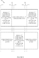
- FIG 4 is a flow chart illustrating a method 400 for comparing execution of a plurality of processing systems that may be performed by one or more processing systems of a computing device, such as computing device 301 shown in Figure 3 , according to aspects of the present disclosure.
- processing system may refer to a processing core of a processor, to a processor, or to a set of components (e.g., processor 310, bus 320, memory 308, and storage 309 shown in Figure 3 ) for performing computer processing.
- the processor 310 is used in performing the steps of the method 400.
- the method 400 depicts an aspect where the computing device compares execution of a program on a first processing system with execution of a program on a second processing system using a first comparator circuit and a second comparator circuit, then stops the comparing using the second comparator circuit and runs a diagnosis program on the second comparator circuit while continuing the comparing using the first comparator circuit, as mentioned above and described in more detail below.
- the method begins by the computing device (e.g., computing device 301) comparing execution of a program on a first processing system of the plurality of processing systems and execution of the program on a second processing system of the plurality of processing systems using a first comparator circuit.
- the processor 310 of the computing device 301 compares execution of a program on processor core 312a to execution of the program on processor core 312b using comparator 314a.
- the method continues by the computing device comparing the execution of the program on the first processing system and the execution of the program on the second processing system using a second comparator circuit.
- the processor 310 of the computing device 301 compares execution of the program on processor core 312a to execution of the program on processor core 312b using comparator 314b.
- the method continues by the computing device running a diagnosis program on the second comparator circuit while the comparing using the first comparator circuit is ongoing.
- the processor 310 of the computing device 301 runs a self-diagnosis program on the comparator 314b while comparing execution of the program on processor core 312a to execution of the program on processor core 312b using comparator 314a.
- a comparator circuit may be disabled from comparing execution of a program on processing systems before a diagnosis program is run on the comparator circuit. After the diagnosis program completes running, the comparator circuit is enabled to compare execution of the program on the processing systems.
- FIG. 5 illustrates an exemplary timeline 500 showing operations for comparing execution of a plurality of processing systems of a lockstep computing system (e.g., computing device 301 shown in Figure 3 ), according to of the present disclosure.
- processing cores of a processor of a lockstep computing system are operating in lockstep.
- the computing device disables a first comparator while the cores remain operating in lockstep and a second comparator is active and verifying that the cores are in lockstep, with no faults detected.
- the diagnosis of the first comparator is complete and the computing device enables the first comparator.
- both of the first and the second comparator are active, checking that the processing cores are operating in lockstep with no faults.
- the computing device disables the second comparator while the cores remain operating in lockstep and the first comparator is active and verifying that the cores are in lockstep, with no faults detected.
- the diagnosis of the second comparator is complete and the computing device enables the second comparator.
- both of the first and the second comparator are active, checking that the processing cores are operating in lockstep with no faults.
- the computing device disables the first comparator while the cores remain operating in lockstep and the second comparator is active and verifying that the cores are in lockstep, with no faults detected.
- the operations at 570 may be a duplicate of the operations at 510, with the computing device continuing to operate in a continuing cycle of disabling and checking each comparator in turn while the other comparator and the processing cores remain active.
- the timeline 500 illustrates some advantages that an embodiment of the present disclosure may have over computing systems using previously known techniques.
- One advantage may be that, because the processing systems (e.g., cores) are not idle while a diagnosis program is run on a comparator, the diagnosis program is not required to complete operation in less time than an idle time duration constraint of the lockstep computing system, unlike the technique associated with the timeline shown in Figure 2A .
- Another advantage may be that there are no times that the processing systems (e.g., cores) of the computing device are not being verified by at least one comparator, unlike the technique associated with the timeline shown in Figure 2B .
- a computing device may have a fail-operational capability. That is, even after a failure has been found in a comparator circuit, the computing device may continue to safely operate with the cores operating in lockstep and the operations of the cores being verified by another comparator circuit that did not suffer a failure.
- the table below illustrates various operational modes that a computing device may have, based on the status of comparators of the computing device. 1 st Comparator status 2 nd Comparator status Computing device operational mode ON ON SAFE ON DIAGNOSIS SAFE DIAGNOSIS ON SAFE ON FAILED FAIL-OPERATIONAL FAILED ON FAIL-OPERATIONAL
- a system e.g., an automobile, a UAV
- a computing device having a fail-operational mode may allow the system to operate safely after detecting a failure in comparator logic. Continued operation in the fail-operational mode may allow time for replacement of a failed component and/or time to reach a service center, where the system may be repaired.
- FIG. 6 is a block diagram illustrating a computing device 601 configured to operate according to aspects of the present disclosure.
- the computing device 601 may be connected to other computing devices via a network 630.
- the network 630 may be a telecommunications network and/or a wide area network (WAN).
- the computing device 601 may be any type of computing device configured to operate with cores in lockstep according to aspects of the present disclosure, including, without limitation, a desktop computer, a server, a laptop computer, a tablet computer, an ADAS, and a UAV control system.
- the computing device 601 generally includes a processor 610 that includes two processing cores 612a, 612b, and two comparator circuits 614a, 614b.
- the processing cores 612 are connected with the comparator circuits 614, each of which may compare the activity of the processing cores 612.
- a second comparator circuit 614b of computing device 601 may duplicate a subset of functionality of a first comparator circuit 614a, while not duplicating all of the functionality of the first comparator circuit.
- the second comparator circuit may verify outputs of processing cores 612a and 612b that affect outputs of the computing device to a controlled system (e.g., an automobile, a UAV) while not verifying accesses to memory (e.g., L1 cache, L2 cache) and other components.
- a computing device may be referred to as having "smart" redundancy.
- a computing device may be configured such that all outputs to a controlled system traverse an advanced extensible interface (AXI) bus and/or an accelerator coherency port (ACP) bus.
- the computing device may have a first comparator circuit that verifies all outputs of the processing systems and a second comparator circuit that verifies outputs from the processing systems on the AXI and ACP buses, but not other outputs from the processing systems.
- the comparator circuits 614 are connected via a bus 620 to a memory 608, an optional network interface device 618, a storage 609, an input device 622, and an output device 624.
- the comparator circuit 614a may compare the outputs of the processing cores 612 to ensure that the processing cores 612 are operating in lockstep.
- the comparator circuit 614b may compare outputs of the processing cores to the controlled system.
- the computing device 601 generally operates according to an operating system (not shown). As above, any operating system supporting the functions disclosed herein may be used.
- the network interface device 618 may be any type of network communications device allowing the computing device 601 to communicate with other computing devices via the network 630.
- computing device 601 is shown with a single processor with multiple cores, the disclosure is not so limited, and aspects of the present disclosure may be practiced in a computing device with a plurality of single-core processors and/or in a computing device with a plurality of multi-core processors.
- “comparator circuit” may refer to one or more components of a processor useful for comparing operations of cores of the processor, one or more components of a computing device separate from a processor and useful for comparing operations of cores of the processor, one or more components of a computing device useful for comparing operations of a plurality of processors (e.g., in a multi-processor computing device), or one or more processors useful for comparing operations of a plurality of other processors.
- a computing device having a first comparator circuit and a second comparator circuit that duplicates a subset of functionality of the first comparator circuit may have a fail-operational capability, as previously described. That is, even after a failure has been found in the second comparator circuit, the computing device may continue to safely operate with the cores operating in lockstep and the operations of the cores being verified by the first comparator circuit, similar to above. And, even after a failure has been found in the first comparator circuit, the computing device may continue to safely operate with the outputs to the controlled system (e.g., an automobile) being verified by the second comparator circuit.
- the controlled system e.g., an automobile
- a computing device having a first comparator circuit and a second comparator circuit that duplicates a subset of functionality of the first comparator circuit may have lower complexity and/or cost less than a computing device having first and second comparator circuits that are duplicates of each other.
- a computing device having a first comparator circuit and a second comparator circuit may enable routine checking of components (e.g., comparator circuits) of a lockstep computing system without requiring a time period of inactivity for the computing device.
- a first comparator circuit of a computing device may be checked by a diagnosis program while the computing system remains active and a second comparator verifies that processing systems of the computing system are operating in lockstep.
- the foregoing disclosed devices and functionalities may be designed and configured into computer files (e.g. RTL, GDSII, GERBER, etc.) stored on computer readable media. Some or all such files may be provided to fabrication handlers who fabricate devices based on such files. Resulting products include semiconductor wafers that are then cut into semiconductor die and packaged into a semiconductor chip. Some or all such files may be provided to fabrication handlers who configure fabrication equipment using the design data to fabricate the devices described herein.
- computer files e.g. RTL, GDSII, GERBER, etc.
- Resulting products formed from the computer files include semiconductor wafers that are then cut into semiconductor die (e.g., the processor 101) and packaged, and may be further integrated into products including, but not limited to, mobile phones, smart phones, laptops, netbooks, tablets, ultrabooks, desktop computers, digital video recorders, set-top boxes, servers, and any other devices where integrated circuits are used.
- semiconductor die e.g., the processor 101
- Resulting products formed from the computer files include semiconductor wafers that are then cut into semiconductor die (e.g., the processor 101) and packaged, and may be further integrated into products including, but not limited to, mobile phones, smart phones, laptops, netbooks, tablets, ultrabooks, desktop computers, digital video recorders, set-top boxes, servers, and any other devices where integrated circuits are used.
- the computer files form a design structure including the circuits described above and shown in the Figures in the form of physical design layouts, schematics, a hardware-description language (e.g., Verilog, VHDL, etc.).
- design structure may be a text file or a graphical representation of a circuit as described above and shown in the Figures.
- Design process preferably synthesizes (or translates) the circuits described below into a netlist, where the netlist is, for example, a list of wires, transistors, logic gates, control circuits, I/O, models, etc. that describes the connections to other elements and circuits in an integrated circuit design and recorded on at least one of machine readable medium.
- the medium may be a storage medium such as a CD, a compact flash, other flash memory, or a hard-disk drive.
- the hardware, circuitry, and method described herein may be configured into computer files that simulate the function of the circuits described above and shown in the Figures when executed by a processor. These computer files may be used in circuitry simulation tools, schematic editors, or other software applications.
- a phrase referring to "at least one of' a list of items refers to any combination of those items, including single members.
- "at least one of: a, b, or c" is intended to cover a, b, c, a-b, a-c, b-c, and a-b-c, as well as any combination with multiples of the same element (e.g., a-a, a-a-a, a-a-b, a-a-c, a-b-b, a- c-c, b-b, b-b-b, b-b-c, c-c, and c-c-c or any other ordering of a, b, and c ) .
Landscapes
- Engineering & Computer Science (AREA)
- Theoretical Computer Science (AREA)
- General Engineering & Computer Science (AREA)
- Quality & Reliability (AREA)
- Physics & Mathematics (AREA)
- General Physics & Mathematics (AREA)
- Computer Hardware Design (AREA)
- Hardware Redundancy (AREA)
Description
- Aspects disclosed herein relate to the field of computer processors. More specifically, aspects disclosed herein relate to periodic non-intrusive diagnosis of lockstep systems.
- Automated systems for vehicle control are gaining in prevalence. Just for automotive driver assist systems (ADAS), some predictions call for a 24% compound annual growth rate over the next five years. Functional safety is a key requirement for these systems, which may include ADAS), unmanned aerial vehicle (UAV) systems, aeronautics systems, and defense systems. For example, in a car, an emergency braking system and an adaptive cruise control cannot afford to see failures, as a failure may result in unbearable consequences, such as a car accident. Similarly, aeronautic control systems also cannot afford failures.
- ISO Standard 26262 requires compliant systems to be designed and configured to avoid unreasonable risks due to hazards caused by malfunctioning behavior of electrical and/or electronic systems. Faults in systems can be random failures due to soft-errors, hardware aging, or circuit failure. In order to be resilient to failures, one approach that has been followed is to have more than one compute engine running in lockstep for redundancy and every activity (e.g., outputs of the compute engines) is compared at memory interfaces, bus interfaces, and/or compute block input/output (I/O) interfaces. If there is a fault in one or more of the compute engines, the fault will be reflected in a comparison mismatch. Systems in which more than one compute engine runs in lockstep for redundancy and every activity is compared at one or more interfaces are referred to herein as lockstep systems.
- If a comparison circuit of a control system (e.g., a control system of a vehicle) develops a fault, then faults in the control system might go undetected, possibly resulting in an unreasonable risk. One technique used to avoid this possibility is to periodically halt the computing activity of the control system, save a context for the control system, perform a hardware diagnosis of the comparison circuit and the rest of the control system, and, if the hardware diagnosis doesn't detect any problems, restore the saved context and resume the activity of the control system. This technique imposes a serious limitation to software architecture of control systems and is frequently very difficult to do, as there is typically an idle-time duration constraint on the operations of the control system. That is, periods of time for the control system to be idle have a maximum allowed length, because the vehicle under the control of the control system cannot be uncontrolled for more than a very short period. This is a serious difficulty in designing a system that requires both safe operation and reliability. Furthermore, as systems are developed that have greater complexity, there are increasing risks of systematic and/or random hardware failures.
- Therefore, techniques for improving the reliability of control systems using comparator circuits are desirable.
- Aspects disclosed herein relate to periodic non-intrusive diagnosis of lockstep systems.
- In one aspect, a method for comparing execution of a plurality of processing systems of a device is provided. The method generally includes comparing execution of a program on a first processing system of the plurality of processing systems and execution of the program on a second processing system of the plurality of processing systems using a first comparator circuit, comparing the execution of the program on the first processing system and the execution of the program on the second processing system using a second comparator circuit, and running a diagnosis program on the second comparator circuit while the comparing using the first comparator circuit is ongoing.
- In another aspect, an apparatus for comparing execution of a plurality of processing systems is provided. The apparatus generally includes a processor configured to compare execution of a program on a first processing system of the plurality of processing systems and execution of the program on a second processing system of the plurality of processing systems using a first comparator circuit, to compare the execution of the program on the first processing system and the execution of the program on the second processing system using a second comparator circuit, and to run a diagnosis program on the second comparator circuit while the comparing using the first comparator circuit is ongoing, and a memory coupled with the processor.
- In still another aspect, an apparatus for comparing execution of a plurality of processing systems is provided. The apparatus generally includes means for comparing execution of a program on a first processing system of the plurality of processing systems and execution of the program on a second processing system of the plurality of processing systems using a first comparator circuit, means for comparing the execution of the program on the first processing system and the execution of the program on the second processing system using a second comparator circuit, and means for running a diagnosis program on the second comparator circuit while the comparing using the first comparator circuit is ongoing.
- In still another aspect, a non-transitory computer-readable medium comprising instructions is provided. The instructions when executed by one or more processing systems cause the one or more processing systems to perform operations comprising comparing execution of a program on a first processing system of the plurality of processing systems and execution of the program on a second processing system of the plurality of processing systems using a first comparator circuit, comparing the execution of the program on the first processing system and the execution of the program on the second processing system using a second comparator circuit, and running a diagnosis program on the second comparator circuit while the comparing using the first comparator circuit is ongoing.
- The claimed aspects may provide one or more advantages over previously known solutions. According to some aspects, diagnosis of components of a lockstep computing system may be performed despite taking longer than an idle time duration constraint of the lockstep computing system while also not allowing processing systems of the lockstep computing system to execute program steps without being verified.
- So that the manner in which the above recited aspects are attained and can be understood in detail, a more particular description of aspects of the disclosure, briefly summarized above, may be had by reference to the appended drawings.
- It is to be noted, however, that the appended drawings illustrate only aspects of this disclosure and are therefore not to be considered limiting of its scope, for the disclosure may admit to other aspects.
-
Figure 1 is a functional block diagram of an exemplary computing device configured to operate according to previously known techniques. -
Figures 2A and 2B illustrate exemplary timelines of techniques for checking operation of a lockstep computing system, according to previously known techniques. -
Figure 3 is a block diagram illustrating a computing device configured to operate according to aspects of the present disclosure. -
Figure 4 illustrates operations that may be performed by one or more processing systems of a computing device, according to aspects of the present disclosure. -
Figure 5 illustrates an exemplary timeline of operations, according to aspects of the present disclosure. -
Figure 6 is a block diagram illustrating a computing device configured to operate according to aspects of the present disclosure. - Aspects disclosed herein provide techniques for periodic non-intrusive diagnosis of lockstep systems. According to aspects of the present disclosure, at least two comparator circuits sit between 2 compute engines (e.g., processors, processor cores) and compare the memory accesses (e.g., to tightly-coupled memory (TCM), level 1 (LI) data cache, level 2 (L2) data cache, L1 instruction cache, L2 instruction cache, system memory, system I/O interfaces) of the compute engines. If the compute engines are parts of a CPU, the comparator circuits may also compare program counters (PCs) of the compute engines. The two comparator circuits may operate in one of three modes. In a first mode, checks of the compute engines are enabled on both comparator circuits, and both comparator circuits are in use to diagnose if the compute engines are successfully in lockstep or not. In a second mode, the first comparator circuit is under self-diagnosis and the second comparator is in use to diagnose if the compute engines are successfully in lockstep or not. In a third mode, the second comparator circuit is under self-diagnosis and the first comparator circuit is in use to diagnose if the compute engines are successfully in lockstep or not.
- Aspects of the present disclosure may have the following advantages over previously known techniques. First, software architecture limitations imposed to support diagnosis in current systems may be avoided, because non-intrusive diagnosis of comparator circuit(s) allows coverage of more of the operations included in the software architecture. As mentioned previously (see above), current techniques have difficulty achieving 100% coverage of operations while meeting idle-time duration constraints. With new more complex use cases, it may be increasingly infeasible to periodically diagnose control circuits using a single comparator circuit. Aspects of the present disclosure allow more time margin and hence better coverage of operations..
-
Figure 1 is a block diagram illustrating acomputing device 101 configured to operate according to previously known techniques. Thecomputing device 101 may be connected to other computing devices via anetwork 130. In general, thenetwork 130 may be a telecommunications network and/or a wide area network (WAN). Generally, thecomputing device 101 may be any type of computing device configured to operate with cores in lockstep, including, without limitation, a desktop computer, a server, a laptop computer, a tablet computer, an ADAS, and a UAV control system. - The
computing device 101 generally includes aprocessor 110 that includes twoprocessing cores comparator circuit 114. The processing cores 112 are connected with thecomparator circuit 114, which compares the activity of the processing cores 112. Thecomparator circuit 114 of theprocessor 110 is connected via a bus 120 to amemory 108, an optionalnetwork interface device 118, astorage 109, aninput device 122, and anoutput device 124. Thecomparator circuit 114 compares the outputs of the processing cores 112 to ensure that the processing cores 112 are operating in lockstep. If a difference is detected in the outputs of the processing cores 112, then thecomparator circuit 114 reports a fault for the processor. Thecomputing device 101 generally operates according to an operating system (not shown). Any operating system supporting the functions disclosed herein may be used. Thenetwork interface device 118 may be any type of network communications device allowing thecomputing device 101 to communicate with other computing devices via thenetwork 130. - The
storage 109 may be a persistent storage device. Although thestorage 109 is shown as a single unit, thestorage 109 may be a combination of fixed and/or removable storage devices, such as fixed disc drives, solid state drives, SAN storage, NAS storage, removable memory cards or optical storage. Thememory 108 and thestorage 109 may be part of one virtual address space spanning multiple primary and secondary storage devices. - The
input device 122 may be any device operable to enable a user to provide input to thecomputing device 101, including an input device operable by a user and/or one or more sensors. For example, theinput device 122 may be an optical sensor. Theoutput device 124 may be any device operable to provide output to a user of thecomputing device 101 and/or to a system under the control of the computing device. For example, theoutput device 124 may be an automobile or a UAV. Although shown separately from theinput device 122, theoutput device 124 andinput device 122 may be combined. For example, a display screen with an integrated touch-screen may be a combinedinput device 122 andoutput device 124. - The operation of the comparator may be represented with a fault detection table as shown below.
Input to Comparator Circuit 114 from CorelInput to Comparator Circuit 114 from Core2Output from Comparator Circuit 1140 0 0 (no fault detected) 0 1 1 (fault detected) 1 0 1 (fault detected) 1 1 0 (no fault detected) processor 110 are different, then thecomparator circuit 114 reports a fault, which may cause the computing device (e.g. a control system) to stop operating. -
Figures 2A and 2B illustrateexemplary timelines computing device 101 shown inFigure 1 ), according to previously known techniques. - In the
timeline 200 shown inFigure 2A , the lockstep computing system is operating in lockstep at 210. At 220, the system performs a self-diagnosis. The self-diagnosis includes operations to save a current context for the lockstep computing device, run a CPU and comparator diagnosis program, and, if no faults are found, restore the saved context. At 230, the lockstep computing system returns to lockstep execution. As mentioned previously, the time used for the operations at 220 must be less than or equal to an idle time duration constraint for the lockstep computing system. - In the
timeline 250 shown inFigure 2B , the lockstep computing system is operating in lockstep at 260. At 270, the system performs a self-diagnosis. The self-diagnosis includes operations to disable comparisons by the comparator while the cores remain operational, run a comparator diagnosis program, and, if no faults are found, enable comparisons by the comparator. At 280, the lockstep computing system returns to lockstep execution. This technique does not have the difficulty of ensuring that the self-diagnosis operation must be less than or equal to an idle time duration constraint for the lockstep computing system (see above), however, while the self-diagnosis of the comparator is being run at 270, the comparator is not checking the operations of the cores at 270, possibly allowing a fault in one of the cores to go undetected. In some systems using this technique, coverage of the self-diagnosis program for the comparator is limited in order to limit the time required by the self-diagnosis program, during which time operation of the cores is not being checked. -
Figure 3 is a block diagram illustrating acomputing device 301 configured to operate according to aspects of the present disclosure. Thecomputing device 301 may be connected to other computing devices via anetwork 330. In general, thenetwork 330 may be a telecommunications network and/or a wide area network (WAN). Generally, thecomputing device 301 may be any type of computing device configured to operate with cores in lockstep according to aspects of the present disclosure, including, without limitation, a desktop computer, a server, a laptop computer, a tablet computer, an ADAS, and a UAV control system. - The
computing device 301 generally includes aprocessor 310 that includes twoprocessing cores comparator circuits computing device 101 inFigure 1 , the comparator circuits 314 are connected via abus 320 to amemory 308, an optionalnetwork interface device 318, astorage 309, aninput device 322, and anoutput device 324. The comparator circuits 314 may compare the outputs of the processing cores 312 to ensure that the processing cores 312 are operating in lockstep. The comparator circuits may compare the outputs of the processing cores at various points, including memory interfaces, bus interfaces, and compute block I/O interfaces. Thecomputing device 301 generally operates according to an operating system (not shown). As above, any operating system supporting the functions disclosed herein may be used. Thenetwork interface device 318 may be any type of network communications device allowing thecomputing device 301 to communicate with other computing devices via thenetwork 330. - The
storage 309 may be a persistent storage device. As above, although thestorage 309 is shown as a single unit, thestorage 309 may be a combination of fixed and/or removable storage devices, such as fixed disc drives, solid state drives, SAN storage, NAS storage, removable memory cards, or optical storage. The memory 238 and thestorage 309 may be part of one virtual address space spanning multiple primary and secondary storage devices. - The
input device 322 may be any device operable to provide input to thecomputing device 301, including an input device operable by a user and/or one or more sensors. For example, theinput device 322 may be an optical sensor. Theoutput device 324 may be any device operable to provide output to a user of thecomputing device 301 and/or to a system under the control of the computing device. For example, theoutput device 324 may be an automobile or a UAV. Although shown separately from theinput device 322, theoutput device 324 andinput device 322 may be combined. For example, a display screen with an integrated touch-screen may be a combinedinput device 322 andoutput device 324. - While the
computing device 301 is shown with a single processor with multiple cores, the disclosure is not so limited, and aspects of the present disclosure may be practiced in a computing device with a plurality of single-core processors and/or in a computing device with a plurality of multi-core processors. As used herein, "comparator circuit" may refer to one or more components of a processor useful for comparing operations of cores of the processor, one or more components of a computing device separate from a processor and useful for comparing operations of cores of the processor, one or more components of a computing device useful for comparing operations of a plurality of processors (e.g., in a multi-processor computing device), or one or more processors useful for comparing operations of a plurality of other processors. -
Figure 4 is a flow chart illustrating amethod 400 for comparing execution of a plurality of processing systems that may be performed by one or more processing systems of a computing device, such ascomputing device 301 shown inFigure 3 , according to aspects of the present disclosure. As used herein, "processing system" may refer to a processing core of a processor, to a processor, or to a set of components (e.g.,processor 310,bus 320,memory 308, andstorage 309 shown inFigure 3 ) for performing computer processing. In at least one aspect, theprocessor 310 is used in performing the steps of themethod 400. Themethod 400 depicts an aspect where the computing device compares execution of a program on a first processing system with execution of a program on a second processing system using a first comparator circuit and a second comparator circuit, then stops the comparing using the second comparator circuit and runs a diagnosis program on the second comparator circuit while continuing the comparing using the first comparator circuit, as mentioned above and described in more detail below. - At
block 410, the method begins by the computing device (e.g., computing device 301) comparing execution of a program on a first processing system of the plurality of processing systems and execution of the program on a second processing system of the plurality of processing systems using a first comparator circuit. For example, theprocessor 310 of thecomputing device 301 compares execution of a program onprocessor core 312a to execution of the program onprocessor core 312b using comparator 314a. - At
block 420, the method continues by the computing device comparing the execution of the program on the first processing system and the execution of the program on the second processing system using a second comparator circuit. Continuing the example above, theprocessor 310 of thecomputing device 301 compares execution of the program onprocessor core 312a to execution of the program onprocessor core 312b using comparator 314b. - At
block 430, the method continues by the computing device running a diagnosis program on the second comparator circuit while the comparing using the first comparator circuit is ongoing. Continuing the example above, theprocessor 310 of thecomputing device 301 runs a self-diagnosis program on thecomparator 314b while comparing execution of the program onprocessor core 312a to execution of the program onprocessor core 312b using comparator 314a. - According to aspects of the present disclosure, a comparator circuit may be disabled from comparing execution of a program on processing systems before a diagnosis program is run on the comparator circuit. After the diagnosis program completes running, the comparator circuit is enabled to compare execution of the program on the processing systems.
-
Figure 5 illustrates anexemplary timeline 500 showing operations for comparing execution of a plurality of processing systems of a lockstep computing system (e.g.,computing device 301 shown inFigure 3 ), according to of the present disclosure. In thetimeline 500, processing cores of a processor of a lockstep computing system are operating in lockstep. At 510, the computing device disables a first comparator while the cores remain operating in lockstep and a second comparator is active and verifying that the cores are in lockstep, with no faults detected. At 520, the diagnosis of the first comparator is complete and the computing device enables the first comparator. At 530, both of the first and the second comparator are active, checking that the processing cores are operating in lockstep with no faults. At 540, the computing device disables the second comparator while the cores remain operating in lockstep and the first comparator is active and verifying that the cores are in lockstep, with no faults detected. At 550, the diagnosis of the second comparator is complete and the computing device enables the second comparator. At 560, both of the first and the second comparator are active, checking that the processing cores are operating in lockstep with no faults. At 570, the computing device disables the first comparator while the cores remain operating in lockstep and the second comparator is active and verifying that the cores are in lockstep, with no faults detected. The operations at 570 may be a duplicate of the operations at 510, with the computing device continuing to operate in a continuing cycle of disabling and checking each comparator in turn while the other comparator and the processing cores remain active. - The
timeline 500 illustrates some advantages that an embodiment of the present disclosure may have over computing systems using previously known techniques. One advantage may be that, because the processing systems (e.g., cores) are not idle while a diagnosis program is run on a comparator, the diagnosis program is not required to complete operation in less time than an idle time duration constraint of the lockstep computing system, unlike the technique associated with the timeline shown inFigure 2A . Another advantage may be that there are no times that the processing systems (e.g., cores) of the computing device are not being verified by at least one comparator, unlike the technique associated with the timeline shown inFigure 2B . - According to aspects of the present disclosure, a computing device may have a fail-operational capability. That is, even after a failure has been found in a comparator circuit, the computing device may continue to safely operate with the cores operating in lockstep and the operations of the cores being verified by another comparator circuit that did not suffer a failure. The table below illustrates various operational modes that a computing device may have, based on the status of comparators of the computing device.
1st Comparator status 2nd Comparator status Computing device operational mode ON ON SAFE ON DIAGNOSIS SAFE DIAGNOSIS ON SAFE ON FAILED FAIL-OPERATIONAL FAILED ON FAIL-OPERATIONAL - According to aspects of the present disclosure, a system (e.g., an automobile, a UAV) using a computing device having a fail-operational mode may allow the system to operate safely after detecting a failure in comparator logic. Continued operation in the fail-operational mode may allow time for replacement of a failed component and/or time to reach a service center, where the system may be repaired.
-
Figure 6 is a block diagram illustrating acomputing device 601 configured to operate according to aspects of the present disclosure. Thecomputing device 601 may be connected to other computing devices via anetwork 630. In general, thenetwork 630 may be a telecommunications network and/or a wide area network (WAN). Generally, thecomputing device 601 may be any type of computing device configured to operate with cores in lockstep according to aspects of the present disclosure, including, without limitation, a desktop computer, a server, a laptop computer, a tablet computer, an ADAS, and a UAV control system. - The
computing device 601 generally includes aprocessor 610 that includes twoprocessing cores comparator circuits second comparator circuit 614b ofcomputing device 601 may duplicate a subset of functionality of afirst comparator circuit 614a, while not duplicating all of the functionality of the first comparator circuit. The second comparator circuit may verify outputs ofprocessing cores - Similar to the
computing device 101 inFigure 1 , the comparator circuits 614 are connected via abus 620 to amemory 608, an optional network interface device 618, astorage 609, aninput device 622, and anoutput device 624. Thecomparator circuit 614a may compare the outputs of the processing cores 612 to ensure that the processing cores 612 are operating in lockstep. Thecomparator circuit 614b may compare outputs of the processing cores to the controlled system. Thecomputing device 601 generally operates according to an operating system (not shown). As above, any operating system supporting the functions disclosed herein may be used. The network interface device 618 may be any type of network communications device allowing thecomputing device 601 to communicate with other computing devices via thenetwork 630. - While the
computing device 601 is shown with a single processor with multiple cores, the disclosure is not so limited, and aspects of the present disclosure may be practiced in a computing device with a plurality of single-core processors and/or in a computing device with a plurality of multi-core processors. As used herein, "comparator circuit" may refer to one or more components of a processor useful for comparing operations of cores of the processor, one or more components of a computing device separate from a processor and useful for comparing operations of cores of the processor, one or more components of a computing device useful for comparing operations of a plurality of processors (e.g., in a multi-processor computing device), or one or more processors useful for comparing operations of a plurality of other processors. - According to aspects of the present disclosure, a computing device having a first comparator circuit and a second comparator circuit that duplicates a subset of functionality of the first comparator circuit may have a fail-operational capability, as previously described. That is, even after a failure has been found in the second comparator circuit, the computing device may continue to safely operate with the cores operating in lockstep and the operations of the cores being verified by the first comparator circuit, similar to above. And, even after a failure has been found in the first comparator circuit, the computing device may continue to safely operate with the outputs to the controlled system (e.g., an automobile) being verified by the second comparator circuit.
- According to aspects of the present disclosure, a computing device having a first comparator circuit and a second comparator circuit that duplicates a subset of functionality of the first comparator circuit may have lower complexity and/or cost less than a computing device having first and second comparator circuits that are duplicates of each other.
- According to aspects of the present disclosure, a computing device having a first comparator circuit and a second comparator circuit may enable routine checking of components (e.g., comparator circuits) of a lockstep computing system without requiring a time period of inactivity for the computing device. For example, as illustrated in
Figure 5 , a first comparator circuit of a computing device may be checked by a diagnosis program while the computing system remains active and a second comparator verifies that processing systems of the computing system are operating in lockstep. - A number of aspects have been described. However, various modifications to these aspects are possible, and the principles presented herein may be applied to other aspects as well. The various tasks of such methods may be implemented as sets of instructions executable by one or more arrays of logic elements, such as microprocessors, embedded controllers, or IP cores.
- The foregoing disclosed devices and functionalities may be designed and configured into computer files (e.g. RTL, GDSII, GERBER, etc.) stored on computer readable media. Some or all such files may be provided to fabrication handlers who fabricate devices based on such files. Resulting products include semiconductor wafers that are then cut into semiconductor die and packaged into a semiconductor chip. Some or all such files may be provided to fabrication handlers who configure fabrication equipment using the design data to fabricate the devices described herein. Resulting products formed from the computer files include semiconductor wafers that are then cut into semiconductor die (e.g., the processor 101) and packaged, and may be further integrated into products including, but not limited to, mobile phones, smart phones, laptops, netbooks, tablets, ultrabooks, desktop computers, digital video recorders, set-top boxes, servers, and any other devices where integrated circuits are used.
- In one aspect, the computer files form a design structure including the circuits described above and shown in the Figures in the form of physical design layouts, schematics, a hardware-description language (e.g., Verilog, VHDL, etc.). For example, design structure may be a text file or a graphical representation of a circuit as described above and shown in the Figures. Design process preferably synthesizes (or translates) the circuits described below into a netlist, where the netlist is, for example, a list of wires, transistors, logic gates, control circuits, I/O, models, etc. that describes the connections to other elements and circuits in an integrated circuit design and recorded on at least one of machine readable medium. For example, the medium may be a storage medium such as a CD, a compact flash, other flash memory, or a hard-disk drive. In another embodiment, the hardware, circuitry, and method described herein may be configured into computer files that simulate the function of the circuits described above and shown in the Figures when executed by a processor. These computer files may be used in circuitry simulation tools, schematic editors, or other software applications.
- As used herein, a phrase referring to "at least one of' a list of items refers to any combination of those items, including single members. As an example, "at least one of: a, b, or c" is intended to cover a, b, c, a-b, a-c, b-c, and a-b-c, as well as any combination with multiples of the same element (e.g., a-a, a-a-a, a-a-b, a-a-c, a-b-b, a-c-c, b-b, b-b-b, b-b-c, c-c, and c-c-c or any other ordering of a, b, and c).
- The previous description of the disclosed aspects is provided to enable a person skilled in the art to make or use the disclosed aspects. Various modifications to these aspects will be readily apparent to those skilled in the art, and the principles defined herein may be applied to other aspects without departing from the scope of the claims. Thus, the present disclosure is not intended to be limited to the aspects shown herein but is to be accorded the widest scope possible consistent with the following claims.
Claims (15)
- A method (400) for comparing execution of a plurality of processing systems of a device, comprising:comparing (410) execution of a program on a first processing system of the plurality of processing systems and execution of the program on a second processing system of the plurality of processing systems using a first comparator circuit;comparing (420) the execution of the program on the first processing system and the execution of the program on the second processing system using a second comparator circuit; and the method is characterised byrunning (430) a diagnosis program on the second comparator circuit while the comparing using the first comparator circuit is ongoing.
- The method of claim 1, further comprising:
running the diagnosis program or another diagnosis program on the first comparator circuit while the comparing using the second comparator circuit is ongoing. - The method of claim 1, further comprising:disabling the second comparator circuit prior to running the diagnosis program; andenabling the second comparator circuit subsequent to running the diagnosis program.
- The method of claim 1, wherein comparing the execution of the program on the first processing system and the execution of the program on the second processing system comprises comparing first values written to a memory by the first processing system with second values written to the memory by the second processing system.
- The method of claim 1, wherein comparing the execution of the program on the first processing system and the execution of the program on the second processing system comprises comparing first values output via one or more buses by the first processing system with second values output via one or more buses by the second processing system.
- The method of claim 5, wherein the one or more buses comprise at least one of an advanced extensible interface, AXI, bus or an accelerator coherency port, ACP, bus.
- The method of claim 1, wherein:comparing the execution of the program on the first processing system and the execution of the program on the second processing system using the first comparator circuit comprises comparing first values output by the first processing system with second values output by the second processing system; andcomparing the execution of the program on the first processing system and the execution of the program on the second processing system using the second comparator circuit comprises comparing third values, output by the first processing system, that are different from the first values with fourth values, output by the second processing system, that are different from the second values.
- The method of claim 1, wherein:the first processing system comprises a first core of a multi-core processor; andthe second processing system comprises a second core of the multi-core processor.
- The method of claim 1, wherein:the first processing system comprises a first processor of the device; andthe second processing system comprises a second processor of the device.
- The method of claim 1, wherein the diagnosis program detects a fault in the second comparator circuit, and the method further comprises:
outputting an indication that the device has the fault and is operating safely. - The method of claim 1, wherein:comparing the execution of the program on the first processing system and the execution of the program on the second processing system using the first comparator circuit comprises comparing outputs from the first processing system and the second processing system that control another device; andcomparing the execution of the program on the first processing system and the execution of the program on the second processing system using the second comparator circuit comprises comparing the outputs from the first processing system and the second processing system that control the other device and comparing other outputs from the first processing system with corresponding other outputs from the second processing system.
- An apparatus (301), comprising:a first processing system (312a);a second processing system (312b);a first comparator circuit (314a) operable to compare execution of a program on the first processing system and execution of the program on the second processing system; anda second comparator circuit (314b) operable to compare the execution of the program on the first processing system and the execution of the program on the second processing system and to run a diagnosis program while the first comparator circuit is comparing the execution of the program on the first processing system and the execution of the program on the second processing system.
- The apparatus of claim 12, wherein the first comparator circuit is operable to run the diagnosis program or another diagnosis program while the second comparator circuit is comparing the execution of the program on the first processing system and the execution of the program on the second processing system.
- The apparatus of claim 12, wherein:at least one of the first processing system, the second processing system, the first comparator circuit, and the second comparator circuit is operable to detect a fault in the second comparator circuit based on the second comparator circuit running the diagnosis program; andat least one of the first processing system and the second processing system is operable to output an indication that the apparatus has the fault and is operating safely.
- A non-transitory computer-readable medium comprising instructions, the instructions when executed by one or more processing systems cause the one or more processing systems to perform a method according to any of claims 1 to 11.
Applications Claiming Priority (2)
| Application Number | Priority Date | Filing Date | Title |
|---|---|---|---|
| US15/410,271 US10331532B2 (en) | 2017-01-19 | 2017-01-19 | Periodic non-intrusive diagnosis of lockstep systems |
| PCT/US2017/065685 WO2018136169A1 (en) | 2017-01-19 | 2017-12-12 | Periodic non-intrusive diagnosis of lockstep systems |
Publications (2)
| Publication Number | Publication Date |
|---|---|
| EP3555748A1 EP3555748A1 (en) | 2019-10-23 |
| EP3555748B1 true EP3555748B1 (en) | 2020-05-13 |
Family
ID=60915647
Family Applications (1)
| Application Number | Title | Priority Date | Filing Date |
|---|---|---|---|
| EP17823301.1A Active EP3555748B1 (en) | 2017-01-19 | 2017-12-12 | Periodic non-intrusive diagnosis of lockstep systems |
Country Status (7)
| Country | Link |
|---|---|
| US (1) | US10331532B2 (en) |
| EP (1) | EP3555748B1 (en) |
| KR (1) | KR102016004B1 (en) |
| CN (1) | CN110140112B (en) |
| SG (1) | SG11201905068VA (en) |
| TW (1) | TWI686695B (en) |
| WO (1) | WO2018136169A1 (en) |
Families Citing this family (9)
| Publication number | Priority date | Publication date | Assignee | Title |
|---|---|---|---|---|
| US11424621B2 (en) | 2020-01-28 | 2022-08-23 | Qualcomm Incorporated | Configurable redundant systems for safety critical applications |
| US11281554B2 (en) * | 2020-03-17 | 2022-03-22 | Samsung Electronics Co., Ltd. | System and method for in-memory computation |
| CN112596916A (en) * | 2021-03-03 | 2021-04-02 | 上海励驰半导体有限公司 | Dual-core lock step error recovery system and method |
| DE102021211709A1 (en) * | 2021-10-18 | 2023-04-20 | Robert Bosch Gesellschaft mit beschränkter Haftung | Data processing network for data processing |
| CN114091380A (en) * | 2021-11-18 | 2022-02-25 | 上海励驰半导体有限公司 | Abnormity detection method and system based on lockstep design |
| CN115372710B (en) * | 2022-10-21 | 2024-02-06 | 西安创联电气科技(集团)有限责任公司 | Automatic resistor testing device |
| US12455799B2 (en) * | 2023-06-16 | 2025-10-28 | Qualcomm Incorporated | Explicit lockstep for functional safety |
| WO2025226795A1 (en) * | 2024-04-23 | 2025-10-30 | Microchip Technology Incorporated | Apparatus and method for fault detection in a dual core lockstep microcontroller |
| GB2641394A (en) * | 2024-05-30 | 2025-12-03 | Imagination Tech Ltd | Processing system configured to process protected tasks |
Family Cites Families (19)
| Publication number | Priority date | Publication date | Assignee | Title |
|---|---|---|---|---|
| US5838894A (en) * | 1992-12-17 | 1998-11-17 | Tandem Computers Incorporated | Logical, fail-functional, dual central processor units formed from three processor units |
| US6862693B2 (en) * | 2001-04-13 | 2005-03-01 | Sun Microsystems, Inc. | Providing fault-tolerance by comparing addresses and data from redundant processors running in lock-step |
| US7392426B2 (en) * | 2004-06-15 | 2008-06-24 | Honeywell International Inc. | Redundant processing architecture for single fault tolerance |
| JP4356634B2 (en) | 2005-03-23 | 2009-11-04 | 日本電気株式会社 | Fault diagnosis circuit, information processing apparatus including the fault diagnosis circuit, fault diagnosis system, and fault diagnosis program |
| DE102005037246A1 (en) * | 2005-08-08 | 2007-02-15 | Robert Bosch Gmbh | Method and device for controlling a computer system having at least two execution units and a comparison unit |
| US8010846B1 (en) | 2008-04-30 | 2011-08-30 | Honeywell International Inc. | Scalable self-checking processing platform including processors executing both coupled and uncoupled applications within a frame |
| US7886195B2 (en) * | 2008-05-05 | 2011-02-08 | Infineon Technologies Ag | Apparatus, system, and method of efficiently utilizing hardware resources for a software test |
| JP5509568B2 (en) * | 2008-10-03 | 2014-06-04 | 富士通株式会社 | Computer apparatus, processor diagnosis method, and processor diagnosis control program |
| CN101794271B (en) * | 2010-03-31 | 2012-05-23 | 华为技术有限公司 | Implementation method and device of consistency of multi-core internal memory |
| US8937622B2 (en) * | 2010-09-20 | 2015-01-20 | Qualcomm Incorporated | Inter-processor communication techniques in a multiple-processor computing platform |
| US8941655B2 (en) * | 2011-09-07 | 2015-01-27 | Qualcomm Incorporated | Memory copy engine for graphics processing |
| US8819485B2 (en) * | 2012-03-12 | 2014-08-26 | Infineon Technologies Ag | Method and system for fault containment |
| EP2813949B1 (en) | 2013-06-11 | 2019-08-07 | ABB Schweiz AG | Multicore processor fault detection for safety critical software applications |
| US9223565B2 (en) * | 2013-10-16 | 2015-12-29 | Google Inc. | Rendering interface objects defined by a separate application |
| JP2015222467A (en) * | 2014-05-22 | 2015-12-10 | ルネサスエレクトロニクス株式会社 | Microcontroller and electronic control device using the same |
| JP6360387B2 (en) * | 2014-08-19 | 2018-07-18 | ルネサスエレクトロニクス株式会社 | Processor system, engine control system, and control method |
| US9823983B2 (en) * | 2014-09-25 | 2017-11-21 | Nxp Usa, Inc. | Electronic fault detection unit |
| US10002056B2 (en) * | 2015-09-15 | 2018-06-19 | Texas Instruments Incorporated | Integrated circuit chip with cores asymmetrically oriented with respect to each other |
| US10089194B2 (en) * | 2016-06-08 | 2018-10-02 | Qualcomm Incorporated | System and method for false pass detection in lockstep dual core or triple modular redundancy (TMR) systems |
-
2017
- 2017-01-19 US US15/410,271 patent/US10331532B2/en active Active
- 2017-12-12 SG SG11201905068VA patent/SG11201905068VA/en unknown
- 2017-12-12 WO PCT/US2017/065685 patent/WO2018136169A1/en not_active Ceased
- 2017-12-12 KR KR1020197020703A patent/KR102016004B1/en active Active
- 2017-12-12 TW TW106143515A patent/TWI686695B/en active
- 2017-12-12 EP EP17823301.1A patent/EP3555748B1/en active Active
- 2017-12-12 CN CN201780082244.0A patent/CN110140112B/en active Active
Non-Patent Citations (1)
| Title |
|---|
| None * |
Also Published As
| Publication number | Publication date |
|---|---|
| EP3555748A1 (en) | 2019-10-23 |
| CN110140112A (en) | 2019-08-16 |
| US10331532B2 (en) | 2019-06-25 |
| WO2018136169A1 (en) | 2018-07-26 |
| BR112019014536A2 (en) | 2020-02-27 |
| TW201830243A (en) | 2018-08-16 |
| TWI686695B (en) | 2020-03-01 |
| KR102016004B1 (en) | 2019-08-29 |
| CN110140112B (en) | 2020-11-17 |
| US20180203778A1 (en) | 2018-07-19 |
| SG11201905068VA (en) | 2019-08-27 |
| KR20190091554A (en) | 2019-08-06 |
Similar Documents
| Publication | Publication Date | Title |
|---|---|---|
| US10331532B2 (en) | Periodic non-intrusive diagnosis of lockstep systems | |
| US10576990B2 (en) | Method and device for handling safety critical errors | |
| CN109872150B (en) | Data processing system with clock synchronization operation | |
| US10761925B2 (en) | Multi-channel network-on-a-chip | |
| CN105373650B (en) | IMA dynamic restructuring modeling methods based on AADL | |
| CN109634171B (en) | Dual-core dual-lock-step two-out-of-two framework and safety platform thereof | |
| CN104714459A (en) | Programmable controller | |
| CN115384535B (en) | Vehicle functional safety monitoring system and method | |
| CN111124780B (en) | UPI Link speed reduction test method, system, terminal and storage medium | |
| US11068337B2 (en) | Data processing apparatus that disconnects control circuit from error detection circuit and diagnosis method | |
| CN103927241B (en) | Memory error avoidance method combining software and hardware and device thereof | |
| Bellotti et al. | How future automotive functional safety requirements will impact microprocessors design | |
| WO2024205732A1 (en) | Processor-based system employing a safety island architecture for fail-safe operation | |
| US9128838B2 (en) | System and method of high integrity DMA operation | |
| HK40005980B (en) | Periodic non-intrusive diagnosis of lockstep systems | |
| HK40005980A (en) | Periodic non-intrusive diagnosis of lockstep systems | |
| CN105446654B (en) | Server control method and rack controller | |
| CN114443423B (en) | A circuit for mutual monitoring between CPU and FPGA | |
| BR112019014536B1 (en) | METHOD FOR COMPARING EXECUTION OF A PLURALITY OF PROCESSING SYSTEMS OF A DEVICE, APPARATUS AND COMPUTER-READABLE MEMORY | |
| US12358648B2 (en) | Control device and rover equipped therewith, control method, and recording medium recorded with program | |
| KR102899319B1 (en) | Apparatus and method for inspecting process and, electronic control apparatus | |
| CN107133186B (en) | Method for simultaneously communicating master TMC (remote control message), slave TMC (remote control message) and BMC (baseboard management controller) | |
| US20260064546A1 (en) | Systems and methods for scalable block-based permanent safety fault tolerance | |
| US11493982B2 (en) | Microcontroller and power management integrated circuit application clustering for safe state management | |
| JP2011081705A (en) | Memory control device and method for controlling the same |
Legal Events
| Date | Code | Title | Description |
|---|---|---|---|
| STAA | Information on the status of an ep patent application or granted ep patent |
Free format text: STATUS: UNKNOWN |
|
| STAA | Information on the status of an ep patent application or granted ep patent |
Free format text: STATUS: THE INTERNATIONAL PUBLICATION HAS BEEN MADE |
|
| PUAI | Public reference made under article 153(3) epc to a published international application that has entered the european phase |
Free format text: ORIGINAL CODE: 0009012 |
|
| STAA | Information on the status of an ep patent application or granted ep patent |
Free format text: STATUS: REQUEST FOR EXAMINATION WAS MADE |
|
| 17P | Request for examination filed |
Effective date: 20190716 |
|
| AK | Designated contracting states |
Kind code of ref document: A1 Designated state(s): AL AT BE BG CH CY CZ DE DK EE ES FI FR GB GR HR HU IE IS IT LI LT LU LV MC MK MT NL NO PL PT RO RS SE SI SK SM TR |
|
| AX | Request for extension of the european patent |
Extension state: BA ME |
|
| GRAP | Despatch of communication of intention to grant a patent |
Free format text: ORIGINAL CODE: EPIDOSNIGR1 |
|
| STAA | Information on the status of an ep patent application or granted ep patent |
Free format text: STATUS: GRANT OF PATENT IS INTENDED |
|
| DAV | Request for validation of the european patent (deleted) | ||
| DAX | Request for extension of the european patent (deleted) | ||
| INTG | Intention to grant announced |
Effective date: 20200102 |
|
| GRAS | Grant fee paid |
Free format text: ORIGINAL CODE: EPIDOSNIGR3 |
|
| GRAA | (expected) grant |
Free format text: ORIGINAL CODE: 0009210 |
|
| STAA | Information on the status of an ep patent application or granted ep patent |
Free format text: STATUS: THE PATENT HAS BEEN GRANTED |
|
| AK | Designated contracting states |
Kind code of ref document: B1 Designated state(s): AL AT BE BG CH CY CZ DE DK EE ES FI FR GB GR HR HU IE IS IT LI LT LU LV MC MK MT NL NO PL PT RO RS SE SI SK SM TR |
|
| REG | Reference to a national code |
Ref country code: GB Ref legal event code: FG4D |
|
| REG | Reference to a national code |
Ref country code: CH Ref legal event code: EP |
|
| REG | Reference to a national code |
Ref country code: DE Ref legal event code: R096 Ref document number: 602017016857 Country of ref document: DE |
|
| REG | Reference to a national code |
Ref country code: AT Ref legal event code: REF Ref document number: 1271159 Country of ref document: AT Kind code of ref document: T Effective date: 20200615 |
|
| REG | Reference to a national code |
Ref country code: CH Ref legal event code: NV Representative=s name: MAUCHER JENKINS PATENTANWAELTE AND RECHTSANWAE, DE |
|
| REG | Reference to a national code |
Ref country code: NL Ref legal event code: FP |
|
| REG | Reference to a national code |
Ref country code: LT Ref legal event code: MG4D |
|
| PG25 | Lapsed in a contracting state [announced via postgrant information from national office to epo] |
Ref country code: PT Free format text: LAPSE BECAUSE OF FAILURE TO SUBMIT A TRANSLATION OF THE DESCRIPTION OR TO PAY THE FEE WITHIN THE PRESCRIBED TIME-LIMIT Effective date: 20200914 Ref country code: IS Free format text: LAPSE BECAUSE OF FAILURE TO SUBMIT A TRANSLATION OF THE DESCRIPTION OR TO PAY THE FEE WITHIN THE PRESCRIBED TIME-LIMIT Effective date: 20200913 Ref country code: SE Free format text: LAPSE BECAUSE OF FAILURE TO SUBMIT A TRANSLATION OF THE DESCRIPTION OR TO PAY THE FEE WITHIN THE PRESCRIBED TIME-LIMIT Effective date: 20200513 Ref country code: FI Free format text: LAPSE BECAUSE OF FAILURE TO SUBMIT A TRANSLATION OF THE DESCRIPTION OR TO PAY THE FEE WITHIN THE PRESCRIBED TIME-LIMIT Effective date: 20200513 Ref country code: LT Free format text: LAPSE BECAUSE OF FAILURE TO SUBMIT A TRANSLATION OF THE DESCRIPTION OR TO PAY THE FEE WITHIN THE PRESCRIBED TIME-LIMIT Effective date: 20200513 Ref country code: NO Free format text: LAPSE BECAUSE OF FAILURE TO SUBMIT A TRANSLATION OF THE DESCRIPTION OR TO PAY THE FEE WITHIN THE PRESCRIBED TIME-LIMIT Effective date: 20200813 Ref country code: GR Free format text: LAPSE BECAUSE OF FAILURE TO SUBMIT A TRANSLATION OF THE DESCRIPTION OR TO PAY THE FEE WITHIN THE PRESCRIBED TIME-LIMIT Effective date: 20200814 |
|
| PG25 | Lapsed in a contracting state [announced via postgrant information from national office to epo] |
Ref country code: BG Free format text: LAPSE BECAUSE OF FAILURE TO SUBMIT A TRANSLATION OF THE DESCRIPTION OR TO PAY THE FEE WITHIN THE PRESCRIBED TIME-LIMIT Effective date: 20200813 Ref country code: HR Free format text: LAPSE BECAUSE OF FAILURE TO SUBMIT A TRANSLATION OF THE DESCRIPTION OR TO PAY THE FEE WITHIN THE PRESCRIBED TIME-LIMIT Effective date: 20200513 Ref country code: LV Free format text: LAPSE BECAUSE OF FAILURE TO SUBMIT A TRANSLATION OF THE DESCRIPTION OR TO PAY THE FEE WITHIN THE PRESCRIBED TIME-LIMIT Effective date: 20200513 Ref country code: RS Free format text: LAPSE BECAUSE OF FAILURE TO SUBMIT A TRANSLATION OF THE DESCRIPTION OR TO PAY THE FEE WITHIN THE PRESCRIBED TIME-LIMIT Effective date: 20200513 |
|
| REG | Reference to a national code |
Ref country code: AT Ref legal event code: MK05 Ref document number: 1271159 Country of ref document: AT Kind code of ref document: T Effective date: 20200513 |
|
| PG25 | Lapsed in a contracting state [announced via postgrant information from national office to epo] |
Ref country code: AL Free format text: LAPSE BECAUSE OF FAILURE TO SUBMIT A TRANSLATION OF THE DESCRIPTION OR TO PAY THE FEE WITHIN THE PRESCRIBED TIME-LIMIT Effective date: 20200513 |
|
| PG25 | Lapsed in a contracting state [announced via postgrant information from national office to epo] |
Ref country code: EE Free format text: LAPSE BECAUSE OF FAILURE TO SUBMIT A TRANSLATION OF THE DESCRIPTION OR TO PAY THE FEE WITHIN THE PRESCRIBED TIME-LIMIT Effective date: 20200513 Ref country code: IT Free format text: LAPSE BECAUSE OF FAILURE TO SUBMIT A TRANSLATION OF THE DESCRIPTION OR TO PAY THE FEE WITHIN THE PRESCRIBED TIME-LIMIT Effective date: 20200513 Ref country code: RO Free format text: LAPSE BECAUSE OF FAILURE TO SUBMIT A TRANSLATION OF THE DESCRIPTION OR TO PAY THE FEE WITHIN THE PRESCRIBED TIME-LIMIT Effective date: 20200513 Ref country code: AT Free format text: LAPSE BECAUSE OF FAILURE TO SUBMIT A TRANSLATION OF THE DESCRIPTION OR TO PAY THE FEE WITHIN THE PRESCRIBED TIME-LIMIT Effective date: 20200513 Ref country code: CZ Free format text: LAPSE BECAUSE OF FAILURE TO SUBMIT A TRANSLATION OF THE DESCRIPTION OR TO PAY THE FEE WITHIN THE PRESCRIBED TIME-LIMIT Effective date: 20200513 Ref country code: DK Free format text: LAPSE BECAUSE OF FAILURE TO SUBMIT A TRANSLATION OF THE DESCRIPTION OR TO PAY THE FEE WITHIN THE PRESCRIBED TIME-LIMIT Effective date: 20200513 Ref country code: SM Free format text: LAPSE BECAUSE OF FAILURE TO SUBMIT A TRANSLATION OF THE DESCRIPTION OR TO PAY THE FEE WITHIN THE PRESCRIBED TIME-LIMIT Effective date: 20200513 Ref country code: ES Free format text: LAPSE BECAUSE OF FAILURE TO SUBMIT A TRANSLATION OF THE DESCRIPTION OR TO PAY THE FEE WITHIN THE PRESCRIBED TIME-LIMIT Effective date: 20200513 |
|
| REG | Reference to a national code |
Ref country code: DE Ref legal event code: R097 Ref document number: 602017016857 Country of ref document: DE |
|
| PG25 | Lapsed in a contracting state [announced via postgrant information from national office to epo] |
Ref country code: SK Free format text: LAPSE BECAUSE OF FAILURE TO SUBMIT A TRANSLATION OF THE DESCRIPTION OR TO PAY THE FEE WITHIN THE PRESCRIBED TIME-LIMIT Effective date: 20200513 Ref country code: PL Free format text: LAPSE BECAUSE OF FAILURE TO SUBMIT A TRANSLATION OF THE DESCRIPTION OR TO PAY THE FEE WITHIN THE PRESCRIBED TIME-LIMIT Effective date: 20200513 |
|
| PLBE | No opposition filed within time limit |
Free format text: ORIGINAL CODE: 0009261 |
|
| STAA | Information on the status of an ep patent application or granted ep patent |
Free format text: STATUS: NO OPPOSITION FILED WITHIN TIME LIMIT |
|
| 26N | No opposition filed |
Effective date: 20210216 |
|
| PG25 | Lapsed in a contracting state [announced via postgrant information from national office to epo] |
Ref country code: MC Free format text: LAPSE BECAUSE OF FAILURE TO SUBMIT A TRANSLATION OF THE DESCRIPTION OR TO PAY THE FEE WITHIN THE PRESCRIBED TIME-LIMIT Effective date: 20200513 |
|
| REG | Reference to a national code |
Ref country code: BE Ref legal event code: MM Effective date: 20201231 |
|
| PG25 | Lapsed in a contracting state [announced via postgrant information from national office to epo] |
Ref country code: IE Free format text: LAPSE BECAUSE OF NON-PAYMENT OF DUE FEES Effective date: 20201212 Ref country code: LU Free format text: LAPSE BECAUSE OF NON-PAYMENT OF DUE FEES Effective date: 20201212 |
|
| PG25 | Lapsed in a contracting state [announced via postgrant information from national office to epo] |
Ref country code: TR Free format text: LAPSE BECAUSE OF FAILURE TO SUBMIT A TRANSLATION OF THE DESCRIPTION OR TO PAY THE FEE WITHIN THE PRESCRIBED TIME-LIMIT Effective date: 20200513 Ref country code: MT Free format text: LAPSE BECAUSE OF FAILURE TO SUBMIT A TRANSLATION OF THE DESCRIPTION OR TO PAY THE FEE WITHIN THE PRESCRIBED TIME-LIMIT Effective date: 20200513 Ref country code: CY Free format text: LAPSE BECAUSE OF FAILURE TO SUBMIT A TRANSLATION OF THE DESCRIPTION OR TO PAY THE FEE WITHIN THE PRESCRIBED TIME-LIMIT Effective date: 20200513 |
|
| PG25 | Lapsed in a contracting state [announced via postgrant information from national office to epo] |
Ref country code: MK Free format text: LAPSE BECAUSE OF FAILURE TO SUBMIT A TRANSLATION OF THE DESCRIPTION OR TO PAY THE FEE WITHIN THE PRESCRIBED TIME-LIMIT Effective date: 20200513 |
|
| PG25 | Lapsed in a contracting state [announced via postgrant information from national office to epo] |
Ref country code: BE Free format text: LAPSE BECAUSE OF NON-PAYMENT OF DUE FEES Effective date: 20201231 |
|
| PG25 | Lapsed in a contracting state [announced via postgrant information from national office to epo] |
Ref country code: SI Free format text: LAPSE BECAUSE OF FAILURE TO SUBMIT A TRANSLATION OF THE DESCRIPTION OR TO PAY THE FEE WITHIN THE PRESCRIBED TIME-LIMIT Effective date: 20200513 |
|
| PGFP | Annual fee paid to national office [announced via postgrant information from national office to epo] |
Ref country code: DE Payment date: 20241111 Year of fee payment: 8 |
|
| PGFP | Annual fee paid to national office [announced via postgrant information from national office to epo] |
Ref country code: GB Payment date: 20241114 Year of fee payment: 8 |
|
| PGFP | Annual fee paid to national office [announced via postgrant information from national office to epo] |
Ref country code: FR Payment date: 20241111 Year of fee payment: 8 |
|
| PGFP | Annual fee paid to national office [announced via postgrant information from national office to epo] |
Ref country code: CH Payment date: 20250101 Year of fee payment: 8 |
|
| PGFP | Annual fee paid to national office [announced via postgrant information from national office to epo] |
Ref country code: NL Payment date: 20251113 Year of fee payment: 9 |