EP3554867B1 - Joint for a vehicle and method for producing such a joint - Google Patents
Joint for a vehicle and method for producing such a joint Download PDFInfo
- Publication number
- EP3554867B1 EP3554867B1 EP17798193.3A EP17798193A EP3554867B1 EP 3554867 B1 EP3554867 B1 EP 3554867B1 EP 17798193 A EP17798193 A EP 17798193A EP 3554867 B1 EP3554867 B1 EP 3554867B1
- Authority
- EP
- European Patent Office
- Prior art keywords
- joint
- sleeve
- outer sleeve
- inner sleeve
- fit device
- Prior art date
- Legal status (The legal status is an assumption and is not a legal conclusion. Google has not performed a legal analysis and makes no representation as to the accuracy of the status listed.)
- Active
Links
Images


Classifications
-
- F—MECHANICAL ENGINEERING; LIGHTING; HEATING; WEAPONS; BLASTING
- F16—ENGINEERING ELEMENTS AND UNITS; GENERAL MEASURES FOR PRODUCING AND MAINTAINING EFFECTIVE FUNCTIONING OF MACHINES OR INSTALLATIONS; THERMAL INSULATION IN GENERAL
- F16C—SHAFTS; FLEXIBLE SHAFTS; ELEMENTS OR CRANKSHAFT MECHANISMS; ROTARY BODIES OTHER THAN GEARING ELEMENTS; BEARINGS
- F16C11/00—Pivots; Pivotal connections
- F16C11/04—Pivotal connections
- F16C11/06—Ball-joints; Other joints having more than one degree of angular freedom, i.e. universal joints
- F16C11/0614—Ball-joints; Other joints having more than one degree of angular freedom, i.e. universal joints the female part of the joint being open on two sides
-
- F—MECHANICAL ENGINEERING; LIGHTING; HEATING; WEAPONS; BLASTING
- F16—ENGINEERING ELEMENTS AND UNITS; GENERAL MEASURES FOR PRODUCING AND MAINTAINING EFFECTIVE FUNCTIONING OF MACHINES OR INSTALLATIONS; THERMAL INSULATION IN GENERAL
- F16C—SHAFTS; FLEXIBLE SHAFTS; ELEMENTS OR CRANKSHAFT MECHANISMS; ROTARY BODIES OTHER THAN GEARING ELEMENTS; BEARINGS
- F16C11/00—Pivots; Pivotal connections
- F16C11/04—Pivotal connections
- F16C11/06—Ball-joints; Other joints having more than one degree of angular freedom, i.e. universal joints
- F16C11/0685—Manufacture of ball-joints and parts thereof, e.g. assembly of ball-joints
- F16C11/069—Manufacture of ball-joints and parts thereof, e.g. assembly of ball-joints with at least one separate part to retain the ball member in the socket; Quick-release systems
-
- B—PERFORMING OPERATIONS; TRANSPORTING
- B60—VEHICLES IN GENERAL
- B60G—VEHICLE SUSPENSION ARRANGEMENTS
- B60G2204/00—Indexing codes related to suspensions per se or to auxiliary parts
- B60G2204/40—Auxiliary suspension parts; Adjustment of suspensions
- B60G2204/416—Ball or spherical joints
-
- B—PERFORMING OPERATIONS; TRANSPORTING
- B60—VEHICLES IN GENERAL
- B60G—VEHICLE SUSPENSION ARRANGEMENTS
- B60G2204/00—Indexing codes related to suspensions per se or to auxiliary parts
- B60G2204/40—Auxiliary suspension parts; Adjustment of suspensions
- B60G2204/44—Centering or positioning means
-
- B—PERFORMING OPERATIONS; TRANSPORTING
- B60—VEHICLES IN GENERAL
- B60G—VEHICLE SUSPENSION ARRANGEMENTS
- B60G2206/00—Indexing codes related to the manufacturing of suspensions: constructional features, the materials used, procedures or tools
- B60G2206/01—Constructional features of suspension elements, e.g. arms, dampers, springs
- B60G2206/80—Manufacturing procedures
- B60G2206/82—Joining
- B60G2206/8209—Joining by deformation
- B60G2206/82092—Joining by deformation by press-fitting
-
- B—PERFORMING OPERATIONS; TRANSPORTING
- B60—VEHICLES IN GENERAL
- B60G—VEHICLE SUSPENSION ARRANGEMENTS
- B60G7/00—Pivoted suspension arms; Accessories thereof
- B60G7/005—Ball joints
-
- F—MECHANICAL ENGINEERING; LIGHTING; HEATING; WEAPONS; BLASTING
- F16—ENGINEERING ELEMENTS AND UNITS; GENERAL MEASURES FOR PRODUCING AND MAINTAINING EFFECTIVE FUNCTIONING OF MACHINES OR INSTALLATIONS; THERMAL INSULATION IN GENERAL
- F16C—SHAFTS; FLEXIBLE SHAFTS; ELEMENTS OR CRANKSHAFT MECHANISMS; ROTARY BODIES OTHER THAN GEARING ELEMENTS; BEARINGS
- F16C2326/00—Articles relating to transporting
- F16C2326/01—Parts of vehicles in general
- F16C2326/05—Vehicle suspensions, e.g. bearings, pivots or connecting rods used therein
-
- F—MECHANICAL ENGINEERING; LIGHTING; HEATING; WEAPONS; BLASTING
- F16—ENGINEERING ELEMENTS AND UNITS; GENERAL MEASURES FOR PRODUCING AND MAINTAINING EFFECTIVE FUNCTIONING OF MACHINES OR INSTALLATIONS; THERMAL INSULATION IN GENERAL
- F16C—SHAFTS; FLEXIBLE SHAFTS; ELEMENTS OR CRANKSHAFT MECHANISMS; ROTARY BODIES OTHER THAN GEARING ELEMENTS; BEARINGS
- F16C2326/00—Articles relating to transporting
- F16C2326/20—Land vehicles
Definitions
- the invention relates to a joint for a vehicle with an outer sleeve, a joint socket for receiving a movably mounted inner joint part, an inner sleeve which is at least partially arranged between the joint socket and the outer sleeve, the inner sleeve having two axially spaced, radially spaced apart on the outer circumference of the inner sleeve has outwardly protruding edge cylinders and the two edge cylinders define a circumferential recess in the form of a groove on the outer circumference of the inner sleeve.
- the invention relates to a method for producing a joint in which an inner sleeve is inserted into an outer sleeve, in which a joint socket is arranged in the inner sleeve, in which an inner joint part is movably supported in the joint socket, and in which a joint socket is mounted in the outer sleeve Lock ring is pressed in for at least partial radial expansion of the outer sleeve.
- Such a joint or such a method is from DE 10 2012 207 527 A1 showing a joint according to the preamble of independent claim 1 and a method for manufacturing such a joint.
- the joint is designed as a sleeve joint which has an outer sleeve extending in an axial direction and two locking rings arranged in the outer sleeve.
- an inner sleeve is arranged in which a ball socket for receiving a ball socket movably mounted in the ball socket is seated.
- the inner sleeve has two radially outwardly protruding edges in the form of edge cylinders, whereby a circumferential free space in the form of a recess or groove results between the inner sleeve and the outer sleeve.
- a ball sleeve joint with a joint socket and a joint housing in the form of an outer sleeve is known. Between the joint housing and the joint shell, two force compensation elements are arranged axially spaced from one another by means of a gap.
- the US 2010/0054851 A1 a ball joint with a joint housing and a joint socket arranged in the joint housing can be seen, with a locking ring for fixing the joint socket being rolled into the joint housing.
- Joints in particular press-in joints, sleeve joints and / or pin joints, can be combined in various embodiments with a vehicle component and / or pressed into a vehicle component.
- the press-in force must reach a minimum value in order to ensure a sufficient tight fit of the joint in the bearing eye.
- the press-in force results from the press-fit overlap between the outer sleeve diameter and the bearing eye diameter and the coefficients of friction.
- the tight fit is usually specified by defined minimum extrusion forces or dynamic loads.
- the joint socket can be protected from the influences of a diameter reduction of the outer sleeve, at least in a predetermined circumferential area.
- the joint socket sits in the outer sleeve with the interposition of the inner sleeve.
- asymmetrical embodiments can be used at right angles to the axial axis of the joint.
- the disadvantage here is that two locking rings can no longer be used and thus no air gap or free space extending over the entire length of the inner sleeve with regard to the pressing of the joint into a bearing eye can be provided.
- the object on which the invention is based is to further develop a joint and a method of the type mentioned at the outset in such a way that pressing the joint into a bearing eye has little or no effect on the moment of resistance to movement of the joint.
- the joint preferably has a preferred axial direction for absorbing an axial load.
- an alternative embodiment is to be provided.
- the joint for a vehicle has an outer sleeve, a joint socket for receiving a movably mounted inner joint part and an inner sleeve which is at least partially arranged between the joint socket and the outer sleeve.
- the inner sleeve has two axially spaced apart on the outer circumference of the inner sleeve circumferential, radially outwardly extending or radially outwardly protruding edge cylinders and the edge cylinders form or define a circumferential recess in the form of a groove on the outer circumference of the inner sleeve.
- a press-fit device formed integrally with the inner sleeve extends radially outward in the region of at least one edge cylinder of the inner sleeve beyond the outer diameter of the edge cylinder.
- the press-fit device formed integrally, in particular in one piece, with the inner sleeve can take over the function of a, in particular further or second, locking ring.
- a separate locking ring or locking cover can thus be dispensed with in the area of the edge cylinder of the inner sleeve with the integral press-fit device.
- the joint preferably only has a single locking ring or locking cover designed as a separate component. This increases the variety of possible designs. In particular, a joint or press-in joint with a preferred axial direction for absorbing high axial loads can be implemented.
- the joint preferably has a joint axis and / or an axial axis about which the joint, the outer sleeve and / or the inner joint part can be moved.
- the hinge axis preferably extends in the axial direction of the outer sleeve.
- the joint axis and the axial axis of the outer sleeve can coincide.
- the outer sleeve and / or the inner sleeve extend in the axial direction of the joint and / or in the axial direction of the joint axis.
- the joint axis is preferably a longitudinal center axis of the joint.
- the joint is designed to be rotationally symmetrical or essentially rotationally symmetrical with respect to the joint axis, the axial axis and / or the longitudinal center axis.
- the joint axis, the axial axis and / or the longitudinal center axis of the joint can run through a center point of the, in particular spherical or spherical, inner joint part.
- the term “radial” can denote any direction or any direction that is perpendicular to the axial direction of the joint, the joint axis, the axial axis and / or the longitudinal center axis.
- the outer sleeve, the inner sleeve and / or the joint socket can form a joint housing or be part of a joint housing.
- the inner joint part is rotatably and / or tiltably mounted in the joint shell.
- the two edge cylinders define and / or determine the two axially spaced apart ends of the inner sleeve.
- the edge cylinders can be ring-like and / or ring-shaped.
- the press-fit device extends radially outward starting from the edge cylinder, in particular the outer circumferential surface of the edge cylinder, of the inner sleeve. If the inner sleeve is pressed into the outer sleeve, the press-fit device rests against the outer sleeve. Starting from the outer circumference and / or the outer circumferential surface of the edge cylinder, the press-fit device can extend radially outward in the direction of an inner side of the outer sleeve. In particular, the inner sleeve has its largest outer diameter in the area of the press-fit device.
- the outer diameter of the inner sleeve in particular in the non-assembled state of the inner sleeve in the outer sleeve, is preferably greater than the inner diameter of the outer sleeve. In this way, a press fit of the inner sleeve within the outer sleeve can be realized.
- At least one circumferential free space preferably two circumferential free spaces
- the free space or spaces can extend over essentially the length of the inner sleeve, in particular over its entire length.
- This free space, in particular the two free spaces is preferably obtained in an assembled state of the joint and in a state that is unassembled in relation to a chassis component.
- at least two free spaces and / or gaps are separated from one another by means of the press-fit device.
- the length of the inner sleeve is preferably its length in the axial direction.
- the inner sleeve is not in contact with the outer sleeve, in particular in the radial direction, except for the press-fit device.
- the inner sleeve can thus be arranged in the outer sleeve in such a way that only the press-fit device rests on the inside of the outer sleeve.
- the joint can be pressed into a bearing eye of a vehicle component while reducing the diameter of the outer sleeve, without this diameter reduction being a significant or significant one Affects the joint shell and / or the storage.
- the diameter of the outer sleeve can preferably be reduced, in particular when the joint is pressed into a bearing eye, while reducing the radial dimensions of the free space, in particular without influencing the joint socket. This can take place until the free space and / or gap is reduced to such an extent that the outer sleeve, in particular in the area of the edge cylinder, rests on the inner sleeve. Only then can a further reduction in the diameter of the outer sleeve lead to a reduction in the diameter of the inner sleeve and thus influence the joint socket.
- the at least one free space is preferably designed as a gap.
- a locking ring or locking cover is arranged inside the outer sleeve.
- the press-fit device can be assigned to the edge cylinder facing away from the locking ring or locking cover.
- the press-fit device can take on the function of an additional or second locking ring or closure cover.
- the press-fit device is preferably designed to be annular.
- the locking ring, the locking cover and / or the press-fit device can be clamped in the radial direction on the outer sleeve on and / or radially against the outer sleeve.
- the locking ring, the locking cover and / or the press-fit device is pressed into the outer sleeve.
- At least some of the forces that occur when the diameter of the outer sleeve is reduced can be introduced into the locking ring, the locking cover and / or the press-fit device.
- the locking ring, the locking cover, the press-fit device, the inner sleeve and / or the outer sleeve can be made of metal, in particular steel.
- the locking ring, the locking cover and the press-fit device can have the same outer diameter.
- a sealing bellows can be mounted in each case on the locking ring and / or the end of the inner sleeve facing away from the locking ring or the locking cover.
- the sealing bellows can extend as far as the inner joint part and bear against it in a sealing manner.
- the press-fit device is designed as a radially outwardly protruding edge, in particular at least one edge cylinder.
- the press-fit device is protruding radially outwards Bridge formed.
- the press fit device can be made comparatively narrow and / or filigree compared to the edge cylinder.
- the width of the press-fit device embodied as an edge and / or web is preferably smaller or narrower than the width of the edge cylinder in the axial direction of the joint and / or in the longitudinal direction of the inner sleeve.
- the press-fit device can surround the outer circumference of the inner sleeve and / or the edge cylinder in a ring-like manner.
- the press-fit device can perform the function of a retaining lug and / or be designed as a, in particular annular, retaining lug.
- the press-fit device is preferably designed in such a way that the press-fit device is negligible when the joint is pressed into a bearing eye. Because the joint is pressed into a bearing eye, in particular a vehicle component, the press-fit device can be pressed flat by means of the outer sleeve and / or pressed into the outer sleeve.
- the press-fit device forms a gap between the outer sleeve and at least the edge cylinder assigned to the press-fit device, in particular when the joint is in an assembled or mounted state and in an unmounted state with respect to a chassis component and / or bearing eye.
- the press-fit device is preferably designed to implement a barb function.
- the press-fit device is designed to hold the inner sleeve in the outer sleeve prior to the assembly of the joint in a chassis component.
- a press fit of the inner sleeve within the outer sleeve can thus be realized by means of the press fit device.
- the tight fit of the inner sleeve within the outer sleeve and when the joint is not mounted in a chassis component and / or bearing eye enables sufficiently accurate and reproducible measurement of the joint, in particular the joint radial elasticity.
- undesired noise generation in particular due to a rattling of the inner sleeve, due to the press fit of the inner sleeve in the outer sleeve, can also be avoided.
- the locking ring or locking cover is preferably supported axially on the inner sleeve and / or on the joint socket and / or lies axially on the inner sleeve and / or on the joint socket.
- the inner sleeve preferably rests against the outer sleeve, in particular with a contact surface facing away from the locking ring or the locking cover.
- the inner sleeve has a material thickening and / or material reinforcement directed radially inward in the area of the press-fit device and / or the edge cylinder with the press-fit device compared to the edge cylinder facing away from the press-fit device.
- the material thickening and / or material reinforcement enables the absorption and / or introduction of high axial forces, preferably in the preferred axial direction of the joint.
- the material thickening and / or material reinforcement is arranged in a region of the inner sleeve facing away from the locking ring or locking cover.
- the material thickening and / or material reinforcement can have a spherical, spherical segment-shaped and / or concave design.
- the joint socket rests against the inside of the inner sleeve with an outer side designed to correspond to the inner side of the inner sleeve.
- the material thickening and / or material reinforcement is so massive that a deformation of the press-fit device due to the joint being pressed into a bearing eye does not represent an obstacle and / or a hindrance.
- the locking ring or the locking cover and the inner sleeve with the integral press-fit device are pressed into the outer sleeve. This ensures that the inner sleeve is held securely in the outer sleeve, in particular in the radial and / or axial direction.
- the joint is preferably designed for a chassis component, the chassis component being provided for mounting on a chassis of a motor vehicle.
- the joint is designed as a ball sleeve joint
- the Inner joint part can be designed as a ball socket and the joint socket as a ball socket.
- the joint can be designed as a ball pivot joint with a ball pivot as the inner joint part.
- the ball pin can have a joint ball and a pin section connected to the joint ball.
- the joint is designed as a press-in joint.
- the pin section can be designed, for example, in the manner of a cylinder or a cone.
- the chassis component can be a link, a spring link, a wheel carrier and / or a spring strut.
- an inner sleeve is introduced and / or pressed into an outer sleeve.
- a joint socket is arranged in the inner sleeve and an inner joint part can be movably supported in the joint socket.
- a, preferably individual, locking ring or closure cover can be pressed into the outer sleeve.
- a gap and / or free space can be created between the inner sleeve and the outer sleeve at least in the area of the locking ring or locking cover.
- the pressing of the locking ring or locking cover into the outer sleeve creates a gap and / or free space in the area of the edge cylinder, in particular facing away from the press-fit device.
- a press-fit device arranged inside the outer sleeve is pressed into the outer sleeve as an integral component of the inner sleeve for at least partial radial expansion of the outer sleeve.
- a gap and / or a free space can be created between the inner sleeve and the outer sleeve in the area of the edge cylinder facing away from the locking ring or locking cover and / or assigned to the press-fit device.
- the joint produced according to the method according to the invention is a joint according to the invention as described above.
- the method is preferably developed in accordance with all of the configurations explained in connection with the joint according to the invention described here. Further the joint described here can be developed in accordance with all of the configurations explained in connection with the method.
- At least one circumferential free space and / or an annular gap can be created or enlarged between the inner sleeve, in particular in the area of the two edge cylinders, and the outer sleeve.
- the press-fit device extending radially in the direction of the outer sleeve is arranged in the area of an edge cylinder of the inner sleeve, in particular in the area of the edge cylinder facing away from the locking ring or closure cover.
- the press-fit device in the area of the edge cylinder assigned to the press-fit device, only the press-fit device is brought into contact with an inside of the outer sleeve when the inner sleeve is pressed into the outer sleeve.
- the inner sleeve can thus be fastened in a press fit in the outer sleeve by means of the press fit device.
- the press-fit device and the edge cylinder facing away from the press-fit device are preferably brought into contact with an inside of the outer sleeve when the inner sleeve is pressed into the outer sleeve.
- the outer diameter of the inner sleeve in the area of the press-fit device is greater than the inner diameter of the outer sleeve when the inner sleeve is pressed into the outer sleeve.
- the outer diameter of the inner sleeve in the area of the edge cylinder when it is pressed into the outer sleeve can be greater than the inner diameter of the outer sleeve.
- the press fit device Due to the press fit device, a press fit or a contact of the edge cylinder assigned to the press fit device on the inside of the outer sleeve is avoided.
- the edge cylinder facing away from the press-fit device can come to rest on the inside of the outer sleeve.
- a press fit and / or a contact of the edge cylinder facing away from the press fit device between the inner sleeve and the inside of the outer sleeve can be released due to a subsequent pressing of the locking ring or closure cover into the outer sleeve.
- the lock ring or the closure cover when pressed into the outer sleeve, has an outer diameter which is greater than the outer diameter of the inner sleeve in the area of the edge cylinder.
- the outside diameter of the locking ring or closure cover is larger than the inside diameter of the outer sleeve.
- the outer diameter of the locking ring or locking cover and the outer diameter of the inner sleeve in the area of the press-fit device are preferably identical.
- the locking ring or locking cover is preferably arranged adjacent to the edge cylinder facing away from the press-fit device.
- the inner sleeve with the press-fit device is first pressed into the outer sleeve, followed by the locking ring or closure cover.
- the locking ring is preferably pressed into the outer sleeve, in particular in the axial direction, until it rests axially on the inner sleeve.
- the locking ring or locking cover rests in the axial direction on the inner sleeve on a side facing away from the press-fit device.
- a gap is formed between edge cylinders spaced apart in the axial direction of the inner sleeve and the outer sleeve.
- a first gap can thus be realized in the area of a first edge cylinder and a second gap in the area of a second edge cylinder.
- the joint socket can be inserted, in particular pressed, into the inner sleeve.
- the inner joint part can be stored or arranged in the joint shell, in particular before the locking ring or locking cover is pressed in.
- the inner joint part is thus preferably supported in the joint socket before the joint socket is inserted and / or pressed into the inner sleeve.
- the respectively assigned axial end can of the outer sleeve are deformed radially inward, in particular bent or rolled.
- the radial ends of the outer sleeve form axial stops for the locking ring or locking cover or for the inner sleeve, in particular a contact surface of the inner sleeve.
- the joint is preferably pressed into a bearing eye of a chassis component with a reduction in the diameter of the outer sleeve, in particular after the locking ring or closure cover has been pressed into the outer sleeve and / or after the axial ends have been reshaped.
- the radial dimensions of the at least one free space and / or gap, preferably in the area of the edge cylinders are reduced and / or used up.
- the press-fit device between the inner sleeve and the outer sleeve can be at least partially deformed or pressed flat and / or pressed into the inside of the outer sleeve.
- the reduction in diameter of the outer sleeve has no or only a slight effect on the radial pretensioning of the bearing of the inner joint part. This is the case until a further reduction in the diameter of the outer sleeve has a dimensional effect on the inner sleeve. However, until this influence occurs, the press-in force is essentially absorbed by the locking ring and the press-fit device.
- the recess and / or a free space can be present in an axially central region of the outer circumferential surface of the inner sleeve, in particular between the two edge cylinders.
- the recess and / or the free space can be designed to be circumferential, groove-like, cylinder-like and / or ring-shaped. This can provide a further possibility of letting existing dimensional overlaps have less of an effect on the mounting of the inner joint part. Should a reduction in the diameter of the inner sleeve nevertheless occur or if it is even necessary because of a high load on the joint, the force in the Essentially transferred to the axial outer areas, in particular via the edge cylinder, to the joint socket.
- the press-fit device formed integrally or in one piece with the inner sleeve can assume the function of an, in particular additional or second, locking ring or replace an additional or second locking ring.
- the press-fit device can perform a double function.
- the inner sleeve can be fixed within the outer sleeve in the radial and / or axial direction by means of the press-fit device. This can facilitate reproducible measurement of the joint.
- a free space and / or gap between the inner sleeve, in particular an edge cylinder of the inner sleeve assigned to the press-fit device, and the inside of the outer sleeve to compensate for a reduction in diameter of the outer sleeve when the joint is pressed into a bearing eye can be created by means of the press-fit device.
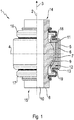
- Figure 1 shows a partially sectioned view of a first joint 1 according to the invention.
- the joint 1 is designed as a sleeve joint, namely a ball sleeve joint.
- the joint 1 is designed to be rotationally symmetrical to a joint axis or longitudinal center axis 2.
- the joint axis or longitudinal center axis 2 runs in the axial direction of the joint 1 according to arrow 3.
- the joint 1 is shown in a top view to the left of the longitudinal center axis 2, whereas a longitudinal section through the joint 1 is shown to the right of the longitudinal center axis 2.
- a transverse central axis 4 is arranged at right angles to the longitudinal central axis 2, the longitudinal central axis 2 and the transverse central axis 4 intersecting at a center point of the joint 1.
- An inner sleeve 6 is introduced into an outer sleeve 5.
- a joint socket 7 is arranged inside the inner sleeve 6.
- An inner joint part 8 is movably mounted in the joint socket 7.
- the joint socket 7 is designed as a ball socket and the inner joint part 8 as a ball sleeve.
- the inner joint part 8 has a joint ball 9 which is mounted rotatably and / or pivotably in relation to the joint socket 7.
- a through hole 10 extends through the inner joint part 8 in the axial direction 8.
- the through hole 10 is cylindrical here, for example.
- a locking ring 11 is pressed into the outer sleeve 5. The locking ring 11 rests axially on the joint socket 7 and the inner sleeve 6.
- the inner sleeve 6 has a material thickening or material reinforcement 12 extending radially inward.
- “radial” is to be understood as an alignment at right angles to the axial direction according to arrow 3 or the longitudinal center axis 2.
- the inner sleeve 6 has a contact surface 13. The contact surface 13 rests axially on the inside of the outer sleeve 5.
- the outer sleeve 5 engages around the inner sleeve 6 in the area of the material reinforcement 12.
- the inner joint part 8 extends axially out of the outer sleeve 5 on both sides and also axially through the locking ring 11 and the inner sleeve 6.
- Sealing bellows 16 and 17 are fastened to axial ends 14 and 15 of inner joint part 8 arranged outside of outer sleeve 5.
- the sealing bellows 16 extends from the axial end 14 to the locking ring 11 and is attached to it.
- the sealing bellows 17 extends from the axial end 15 to the inner sleeve 6 and is attached to it.
- axial ends 18, 19 of the outer sleeve 5 are each bent radially inward, so that the end 18 rests axially on the locking ring 11 and the end 19 rests axially on the contact surface 13.
- the axial ends 18, 19 can also fix the locking ring 11 and the inner sleeve 6 in a form-fitting manner in the outer sleeve 5.
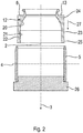
- Figure 2 shows a sectional view of the outer sleeve 5 and the inner sleeve 6 before they are assembled together.
- the inner sleeve 6 has a concave and / or spherical segment-shaped inner side area 20.
- the inner side area 20 of the outer sleeve 5 merges into an annular and / or cylindrical inner side area 21.
- a coaxially encircling recess 23 is made, which is delimited axially on both sides.
- the recess 23 is formed like a groove.
- the axially spaced apart edges of the inner sleeve 6 are designed as edge cylinders 24, 25 in this exemplary embodiment.
- the edge cylinders 24, 25 protrude radially outward beyond the recess 23.
- the inner sleeve 6 thus has a larger outer diameter in the area of the two edge cylinders 24, 25 than in the area of the recess 23.
- the outer diameter of the inner sleeve 6 in the area of the edge cylinders 24, 25 is greater than the inner diameter of the outer sleeve 5.
- Figure 2 and the one described in more detail below Figures 3 to 5 different steps for producing the joint 1 are shown.
- the outer sleeve 5 is placed on an assembly tool 26.
- the inner sleeve 6 is then pressed into the outer sleeve 5 in the direction of the arrow 3.
- the force required for pressing in is indicated by arrow 27.
- the outer diameter of the inner sleeve 6 is greater than the inner diameter of the outer sleeve 5, at least in the area of the edge cylinders 24, 25.
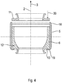
- Figure 3 shows a sectional view of the outer sleeve 5 with an installed inner sleeve 6.
- the inner sleeve 6 is arranged in the outer sleeve 5 with a press fit.
- the diameter of the inner sleeve 6 has been reduced and the diameter of the outer sleeve 5 has increased.
- These changes in diameter are indicated by arrows 28 and 29, respectively.
- the axial end 19 of the outer sleeve 5 has been reshaped radially inward, so that the axial end 19 rests against the contact surface 13 of the inner sleeve 6.
- the radial end 19 of the outer sleeve 5 extends at right angles to the longitudinal center axis 12.
- the contact surface 13 extends in the radial direction, namely at right angles to the longitudinal center axis 2 in this embodiment.
- Figure 4 shows a sectional view of the outer sleeve 5 with the mounted inner sleeve 6 according to FIG Figure 3 and before assembly of the locking ring 11.
- the outer sleeve 5 with the pressed-in inner sleeve 6 has been detached from the assembly tool 26 in order to then press the locking ring 11 into the outer sleeve 5 in the opposite direction of arrow 3 until the locking ring 11 rests axially on the inner sleeve 6 .
- the state before the locking ring 11 is pressed in can be seen, the force required for pressing in being indicated by arrow 30.
- the locking ring 11 is pressed into the outer sleeve 5 in a region of the axial end 18 facing away from the material reinforcement 12 or the axial end 19.
- the joint socket 7 and the inner joint part 8 are not shown in more detail for better clarity.
- the joint socket 7 and the inner joint part 8 are usually arranged in the inner sleeve 6. Only then is the locking ring 11 pressed into the outer sleeve 5.
- the joint socket 7 is pretensioned axially in the direction of the material reinforcement 12 of the inner sleeve 6 with the aid of the locking ring 11.
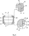
- FIG Figure 5 shows a sectional view of the outer sleeve 5 with the mounted inner sleeve 6 according to FIG Figure 3 and the assembled locking ring 11. Furthermore, FIG Figure 5 Two partial sections A and B. This shows the pressed-in state of the locking ring 11, whereby the outer diameter of the locking ring 11 was reduced due to the pressing-in of the locking ring 11 and the diameter of the outer sleeve 5 was increased at least in the area of the locking ring 11 and the edge cylinder 25.
- the enlargement of the diameter of the outer sleeve 5 brought about by the pressing in of the locking ring 11 can also be referred to as a radial expansion. This radial expansion is so large that the press fit of the inner sleeve 6 in the area of the edge cylinder 25 is released.
- a free space or gap 31 is thus created between the outer peripheral surface of the inner sleeve 6 in the area of the edge cylinder 25 and the inside of the outer sleeve 5 due to the pressing in of the locking ring 11.
- the axial end 18 of the outer sleeve 5 is reshaped radially inward.
- the locking ring 11 can be fixed in the axial direction according to arrow 3 between the axial end 18 and the inner sleeve 6.
- Partial section B shows a press-fit device 32.
- the press-fit device 32 is designed as an integral or one-piece component of the inner sleeve 6.
- the press-fit device 32 is designed as an annular web encircling the outer circumference of the inner sleeve 6.
- the press fit device 32 extends radially outward.
- the outer diameter of the press-fit device 32 is larger than the outer diameter of the inner sleeve 6 in the region of the edge cylinder 24, as a result of which the press-fit device projects radially outward beyond the edge cylinders 24, 25.
- the press-fit device 32 is arranged in the region of an edge of the edge cylinder 25.
- the press-fit device 32 is arranged in the area of an axially inwardly directed edge of the edge cylinder 24.
- the press-fit device 32 By means of the press-fit device 32, the inner sleeve 6 is pressed into the outer sleeve 5 in a fixed position, in particular in the radial direction, in the area of the edge cylinder 24. Compared to the edge cylinder 24, the press fit device 32 is designed to be comparatively narrow. Due to the press fit device 32, a free space or gap 33 is formed between the outer circumferential surface of the inner sleeve 6 in the area of the edge cylinder 24 and the inside of the outer sleeve 5.
- the press-fit device 32 has a barb contour. As a result, the risk of undesired loosening of the inner sleeve 6 in the axial direction can be further reduced.
- the gaps 31, 33 and the recess 23 form annular free spaces between the inner sleeve 6 and the outer sleeve 5.
- the locking ring 11 and the press-fit device 32 are matched to one another in such a way that the width of the gaps 31, 33 is identical or at least substantially the same are great.
- FIG Figure 6 shows a partially sectioned view of the joint 1 according to the invention according to FIG Figure 1 after it has been pressed into a bearing eye 34.
- the joint shell 7 and the inner joint part 8 have been omitted.
- two partial sections C and D are shown.
- the bearing eye 34 is part of a chassis component 35.
- the chassis component 35 is designed as a link. To the left of the longitudinal center axis 2, part of the chassis component 35 is shown in plan view, with a part of the chassis component 35 being shown in section to the right of the longitudinal center axis 2.
- the bearing eye 34 is designed as a cylindrical through hole arranged in the chassis component 35. Due to the pressing of the joint 1 with the outer sleeve 5 into the bearing eye 34, the outer sleeve 5, the locking ring 11 and the inner sleeve 6 have been reduced in their diameters. Furthermore, the diameter of the bearing eye 34 was increased due to the press-fitting. The respective enlargements or reductions in diameter are indicated by means of arrows 36, 37 and 38.
- the gap 31 and the gap 33 have disappeared or the associated free space has been used up due to the diameter reduction of the outer sleeve 5.
- the recess 23 is still present between the two edge cylinders 24, 25.
- a reduction in the diameter of the inner sleeve 6 results in an increase in the radial prestressing of the joint socket 7, with the radial forces exerted by the joint socket 7 on the joint ball 9 being greatest, especially at the level of the edge cylinders 24, 25, when viewed in the axial direction 3.
- the joint 1 can absorb higher loads or forces in a preferred axial direction.
- the preferred axial direction for absorbing axial loads or forces is opposed to the axial direction according to arrow 3.
- the press-fit device 32 When the joint 1 is pressed into the bearing eye 34, due to the diameter reduction of the outer sleeve 5, the press-fit device 32 is deformed, reshaped and / or used up in such a way that the outer sleeve 5 lies in the area of the press-fit device 32 or the edge cylinder 24 on the outer circumferential surface of the inner sleeve 6 comes.
- the material of the press-fit device 32 can be pressed and / or reshaped into the outer sleeve 5 and / or in the direction of the recess 23.
- the material reinforcement 12 serves as a type of counter-bearing for the reshaping or deformation of the press-fit device 32 when the joint 1 or the outer sleeve 5 is pressed into the bearing eye 34.
- FIG. 7 shows a schematic flow diagram for a method according to the invention.
- the outer sleeve 5 is provided according to step S11.
- the outer sleeve 5 is introduced into an assembly tool 26.
- the inner sleeve 6 is pressed into the outer sleeve 5.
- the inner sleeve 6 has a press-fit device 32 which is formed integrally or in one piece with the inner sleeve 6.
- the inner sleeve 6 in the area of the edge cylinders 24, 25 and the press-fit device 32 has an outer diameter that is larger than the inner diameter of the outer sleeve 5 Outer diameter of the two edge cylinders 24, 25.
- a press fit of the inner sleeve 6 is produced in the outer sleeve 5.
- the press fit device 32 and the edge cylinder 25, which is spaced apart from the press fit device 32 lie against the inside of the outer sleeve 5.
- the locking ring 11 is then pressed into the outer sleeve 5 in accordance with step S13.
- the locking ring 11 is pressed in immediately adjacent or adjacent to the edge cylinder 25. Before the locking ring 11 is pressed in, it has an outer diameter that is greater than the inner diameter of the outer sleeve 5.
- a gap 31 is formed by means of the locking ring 11 in the area of the edge cylinder 25 and a gap 33 is formed by means of the press-fit device 32 in the area of the edge cylinder 24.
- a closure cover can be used alternatively and instead of a locking ring 11 if the joint is designed as a ball and socket joint instead of a ball socket joint.
- step S14 the joint 1 is pressed into a bearing eye 34. Due to this press-in process, the diameter of the outer sleeve 5 is reduced and the free space due to the gaps 31, 33 is used up. Thus, the outer circumferential surfaces of the edge cylinders 24, 25 lie after the pressing of the joint 1 into the bearing eye 34 on the inside of the outer sleeve 5.
- the method according to the invention is then ended in accordance with step S15.
- the method according to the invention for producing the joint 1 can already be ended after step S13 has ended.
- the axial edge 19 of the outer sleeve 5 is reshaped radially inward after performing step S12 and before performing step S13.
- the axial end 18 of the outer sleeve 5 can be reshaped radially inward after the locking ring 11 has been pressed in according to step S13 and before step S14 or the end of the method. Due to the deformation of the axial ends 18, 19, the inner sleeve 6 and / or the joint socket 7 is fixed and / or pretensioned in the axial direction.
- Figure 8 4 shows a partially sectioned view of a further joint 39 according to the invention.
- the joint 39 is designed as a pivot joint, namely a ball pivot joint.
- the joint 39 is designed to be rotationally symmetrical to a joint axis or longitudinal center axis 2.
- the joint axis or longitudinal center axis 2 runs in the axial direction of the joint 39 according to arrow 3.
- the joint 39 is shown in a top view to the left of the longitudinal center axis 2, whereas a longitudinal section through the joint 39 is shown to the right of the longitudinal center axis 2.
- a transverse central axis 4 is arranged at right angles to the longitudinal central axis 2, the longitudinal central axis 2 and the transverse central axis 4 intersecting at a center point of the joint 1.
- An inner sleeve 6 is introduced into an outer sleeve 5.
- a joint socket 7 is arranged inside the inner sleeve 6.
- An inner joint part 40 is movably mounted in the joint socket 7.
- the joint socket 7 is embodied as a spherical socket and the inner joint part 40 is embodied as a ball pin.
- the inner joint part 40 has a joint ball 42 which is mounted rotatably and / or pivotably in relation to the joint socket 7.
- a closure cover 41 is pressed into the outer sleeve 5.
- the closure cover 41 rests axially on the joint socket 7 and the inner sleeve 6.
- the closure cap 41 is formed so as to be arched radially outward.
- the inner joint part 40 has a pin section 43.
- the pin section 43 is connected to the joint ball 42.
- the pin section 43 is essentially cylindrical.
- the pin portion 43 can be designed, for example, conical.
- the pin section 43 has a circumferential groove 44.
- the inner sleeve 6 In a region facing away from the closure cover 41 or at an end of the inner sleeve 6 facing away from the closure cover 41, the inner sleeve 6 has a material thickening or material reinforcement 12 extending radially inward. In the area of the material reinforcement 12 and on a side facing away from the closure cover 41, the inner sleeve 6 has a contact surface 13. The contact surface 13 rests axially on the inside of the outer sleeve 5. In this exemplary embodiment, the outer sleeve 5 engages around the inner sleeve 6 in the area of the material reinforcement 12.
- the inner joint part 40 extends axially out of the outer sleeve 5 by means of the pin section 43 and through the inner sleeve 6 on the side facing away from the closure cover 41.
- a sealing bellows 46 is attached to an axial end 45 of the outer sleeve 5 facing away from the closure cover 41.
- the sealing bellows 46 extends from an outer circumference of the pin section 43 to the inner sleeve 6 and is attached to it.
- axial ends 18, 19 of the outer sleeve 5 are each bent radially inward, so that the end 18 rests axially on the closure cover 41 and the end 19 rests axially on the contact surface 13.
- the axial ends 18, 19 can thus also fix the closure cover 41 and the inner sleeve 6 in a form-fitting manner in the outer sleeve 5.
- the manufacture or assembly of the joint 39 takes place analogously to the description of the joint 1 according to FIGS Figures 2 to 7 .
- the joint 39 thus also has a press fit device 32.
- a locking cover 41 is used instead of the locking ring 11 at the joint 39.
Landscapes
- Engineering & Computer Science (AREA)
- General Engineering & Computer Science (AREA)
- Mechanical Engineering (AREA)
- Pivots And Pivotal Connections (AREA)
- Vehicle Body Suspensions (AREA)
Description
Die Erfindung betrifft ein Gelenk für ein Fahrzeug mit einer Außenhülse, einer Gelenkschale zum Aufnehmen eines bewegbar gelagerten Gelenkinnenteils, einer Innenhülse, die mindestens teilweise zwischen der Gelenkschale und der Außenhülse angeordnet ist, wobei die Innenhülse zwei axial voneinander beabstandete am Außenumfang der Innenhülse umlaufende, radial nach außen vorstehende Randzylinder aufweist und die beiden Randzylinder eine umlaufende Vertiefung in Gestalt einer Nut am Außenumfang der Innenhülse bestimmen. Des Weiteren betrifft die Erfindung ein Verfahren zum Herstellen eines Gelenkes, bei dem in eine Außenhülse eine Innenhülse eingebracht wird, bei dem eine Gelenkschale in der Innenhülse angeordnet wird, bei dem in der Gelenkschale ein Gelenkinnenteil bewegbar gelagert wird, und bei dem in die Außenhülse ein Verschlussring zum mindestens teilweisen radialen Aufweiten der Außenhülse eingepresst wird.The invention relates to a joint for a vehicle with an outer sleeve, a joint socket for receiving a movably mounted inner joint part, an inner sleeve which is at least partially arranged between the joint socket and the outer sleeve, the inner sleeve having two axially spaced, radially spaced apart on the outer circumference of the inner sleeve has outwardly protruding edge cylinders and the two edge cylinders define a circumferential recess in the form of a groove on the outer circumference of the inner sleeve. Furthermore, the invention relates to a method for producing a joint in which an inner sleeve is inserted into an outer sleeve, in which a joint socket is arranged in the inner sleeve, in which an inner joint part is movably supported in the joint socket, and in which a joint socket is mounted in the outer sleeve Lock ring is pressed in for at least partial radial expansion of the outer sleeve.
Ein derartiges Gelenk bzw. ein derartiges Verfahren ist aus der
Der
Gelenke, insbesondere Einpressgelenke, Hülsengelenke und/oder Zapfengelenke, können in verschiedenen Ausführungsformen mit einem Fahrzeugbauteil kombiniert und/oder in ein Fahrzeugbauteil eingepresst werden. Aufgrund des Einpressens des Gelenks bzw. der Außenhülse in ein Lagerauge kann jedoch ein Zielkonflikt entstehen. Zum einen muss die Einpresskraft einen Mindestwert erreichen, um einen hinreichenden Festsitz des Gelenks in dem Lagerauge zu gewährleisten. Insbesondere resultiert die Einpresskraft aus der Einpressüberdeckung von Außenhülsendurchmesser zum Lageraugendurchmesser und den Reibbeiwerten. Der feste Sitz wird üblicherweise durch festgelegte minimale Auspresskräfte oder dynamische Belastungen vorgegeben. Es besteht jedoch die Gefahr, dass aufgrund der Einpressüberdeckung der Außenhülsendurchmesser derart reduziert wird, dass das Bewegungswiderstandsmoment des Gelenks ansteigt. Eine Veränderung des Bewegungswiderstandsmomentes aufgrund des Einpressens des Gelenkes in ein Lagerauge ist häufig unerwünscht und kann die Fahrwerksabstimmung beeinträchtigen.Joints, in particular press-in joints, sleeve joints and / or pin joints, can be combined in various embodiments with a vehicle component and / or pressed into a vehicle component. However, because the joint or the outer sleeve is pressed into a bearing eye, a conflict of objectives can arise. On the one hand, the press-in force must reach a minimum value in order to ensure a sufficient tight fit of the joint in the bearing eye. In particular, the press-in force results from the press-fit overlap between the outer sleeve diameter and the bearing eye diameter and the coefficients of friction. The tight fit is usually specified by defined minimum extrusion forces or dynamic loads. However, there is a risk that, due to the press-fit overlap, the outer sleeve diameter is reduced to such an extent that the moment of resistance to movement of the joint increases. A change in the moment of resistance to movement due to the pressing of the joint into a bearing eye is often undesirable and can affect the chassis tuning.
Gemäß dem bekannten Stand der Technik kann dieser Zielkonflikt mittels einer geeignet ausgebildeten Innenhülse gelöst werden. Hierbei kann mittels der Innenhülse die Gelenkschale mindestens in einem vorgegebenen Umfangsbereich vor den Einflüssen einer Durchmesserreduzierung der Außenhülse geschützt werden. Insbesondere sitzt die Gelenkschale unter Zwischenschaltung der Innenhülse in der Außenhülse. Mittels der Innenhülse ist realisierbar, dass das Gelenk in ein Lagerauge eines Fahrzeugbauteils eingepresst wird, ohne eine auf die Gelenkschale wirkende radiale Spannung zu verändern oder zu stark zu verändern. Das bei der Herstellung des Gelenks vorgesehene bzw. bei dessen Herstellung eingestellte Reibmoment bleibt unverändert oder wird lediglich gering bzw. vernachlässigbar beeinflusst.According to the known prior art, this conflict of objectives can be resolved by means of a suitably designed inner sleeve. Here, by means of the inner sleeve, the joint socket can be protected from the influences of a diameter reduction of the outer sleeve, at least in a predetermined circumferential area. In particular, the joint socket sits in the outer sleeve with the interposition of the inner sleeve. By means of the inner sleeve it can be realized that the joint is pressed into a bearing eye of a vehicle component without changing or changing too much a radial tension acting on the joint shell. The frictional torque provided during manufacture of the joint or set during its manufacture remains unchanged or is only influenced slightly or negligibly.
Bei dem bekannten Stand der Technik entstehen durch das Einpressen der beiden Verschlussringe im Bereich der beiden Randzylinder Luftspalte zwischen der Innenhülse und der Außenhülse. Aufgrund des Einpressens des Gelenkes in ein Lagerauge eines Fahrzeugbauteils wird dieser Luftspalt aufgebraucht. Die Ausführungsformen gemäß dem Dokument
Für den Fall, dass jedoch hohe axiale Lasten von dem Gelenk aufgenommen werden sollen, können rechtwinklig zur Axialachse des Gelenks unsymmetrisch ausgebildete Ausführungsformen eingesetzt werden. Hierbei ist jedoch von Nachteil, dass nicht mehr zwei Verschlussringe eingesetzt werden können und somit kein Luftspalt bzw. über die gesamte Länge der Innenhülse sich erstreckender Freiraum im Hinblick auf das Einpressen des Gelenks in ein Lagerauge bereitgestellt werden kann.However, in the event that high axial loads are to be absorbed by the joint, asymmetrical embodiments can be used at right angles to the axial axis of the joint. The disadvantage here, however, is that two locking rings can no longer be used and thus no air gap or free space extending over the entire length of the inner sleeve with regard to the pressing of the joint into a bearing eye can be provided.
Es ist die der Erfindung zu Grunde liegende Aufgabe, ein Gelenk und ein Verfahren der eingangs genannten Art derart weiter zu entwickeln, dass ein Einpressen des Gelenks in ein Lagerauge keine oder allenfalls geringe Auswirkungen auf das Bewegungswiderstandsmoment des Gelenks hat. Vorzugsweise hat das Gelenk eine axiale Vorzugsrichtung zum Aufnehmen einer axialen Last. Insbesondere soll eine alternative Ausführungsform bereitgestellt werden.The object on which the invention is based is to further develop a joint and a method of the type mentioned at the outset in such a way that pressing the joint into a bearing eye has little or no effect on the moment of resistance to movement of the joint. The joint preferably has a preferred axial direction for absorbing an axial load. In particular, an alternative embodiment is to be provided.
Die der Erfindung zu Grunde liegende Aufgabe wird mit einem Gelenk nach Anspruch 1 und mittels eines Verfahrens nach Anspruch 10 gelöst. Bevorzugte Weiterbildungen der Erfindung finden sich in den Unteransprüchen und in der nachfolgenden Beschreibung.The object on which the invention is based is achieved with a joint according to claim 1 and by means of a method according to
Demnach weist das Gelenk für ein Fahrzeug eine Außenhülse, eine Gelenkschale zum Aufnehmen eines bewegbar gelagerten Gelenkinnenteils und eine Innenhülse auf, die mindestens teilweise zwischen der Gelenkschale und der Außenhülse angeordnet ist. Die Innenhülse hat zwei axial voneinander beabstandete am Außenumfang der Innenhülse umlaufende, sich radial nach außen erstreckende bzw. radial nach außen vorstehende Randzylinder und die Randzylinder bilden bzw. bestimmen eine umlaufende Vertiefung in Gestalt einer Nut am Außenumfang der Innenhülse. Des Weiteren erstreckt sich eine integral mit der Innenhülse ausgebildete Presssitzeinrichtung im Bereich mindestens eines Randzylinders der Innenhülse über den Außendurchmesser des Randzylinders hinaus radial nach außen.Accordingly, the joint for a vehicle has an outer sleeve, a joint socket for receiving a movably mounted inner joint part and an inner sleeve which is at least partially arranged between the joint socket and the outer sleeve. The inner sleeve has two axially spaced apart on the outer circumference of the inner sleeve circumferential, radially outwardly extending or radially outwardly protruding edge cylinders and the edge cylinders form or define a circumferential recess in the form of a groove on the outer circumference of the inner sleeve. Furthermore, a press-fit device formed integrally with the inner sleeve extends radially outward in the region of at least one edge cylinder of the inner sleeve beyond the outer diameter of the edge cylinder.
Hierbei ist von Vorteil, dass die integral, insbesondere einstückig, mit der Innenhülse ausgebildete Presssitzeinrichtung die Funktion eines, insbesondere weiteren oder zweiten, Verschlussringes übernehmen kann. Somit kann im Bereich des Randzylinders der Innenhülse mit der integralen Presssitzeinrichtung auf einen separaten Verschlussring oder Verschlussdeckel verzichtet werden. Vorzugsweise weist das Gelenk lediglich einen einzelnen als separates Bauteil ausgebildeten Verschlussring oder Verschlussdeckel auf. Hierdurch wird die Vielfalt möglicher Konstruktionen vergrößert. Insbesondere ist ein Gelenk oder Einpressgelenk mit einer axialen Vorzugsrichtung zum Aufnehmen hoher axialer Lasten realisierbar.The advantage here is that the press-fit device formed integrally, in particular in one piece, with the inner sleeve can take over the function of a, in particular further or second, locking ring. A separate locking ring or locking cover can thus be dispensed with in the area of the edge cylinder of the inner sleeve with the integral press-fit device. The joint preferably only has a single locking ring or locking cover designed as a separate component. This increases the variety of possible designs. In particular, a joint or press-in joint with a preferred axial direction for absorbing high axial loads can be implemented.
Vorzugsweise weist das Gelenk eine Gelenkachse und/oder Axialachse auf, um die das Gelenk, die Außenhülse und/oder das Gelenkinnenteil bewegbar ist. Vorzugsweise erstreckt sich die Gelenkachse in axialer Richtung der Außenhülse. Die Gelenkachse und die axiale Achse der Außenhülse können zusammenfallen. Insbesondere erstrecken sich die Außenhülse und/oder die Innenhülse in axialer Richtung des Gelenks und/oder in axialer Richtung der Gelenkachse. Vorzugsweise handelt es sich bei der Gelenkachse um eine Längsmittelachse des Gelenks. Insbesondere ist das Gelenk bezüglich der Gelenkachse, der Axialachse und/oder der Längsmittelachse rotationssymmetrisch oder im Wesentlichen rotationssymmetrisch ausgebildet. Die Gelenkachse, die Axialachse und/oder die Längsmittelachse des Gelenks kann durch einen Mittelpunkt des, insbesondere kugelartigen oder kugelförmigen, Gelenkinnenteils verlaufen.The joint preferably has a joint axis and / or an axial axis about which the joint, the outer sleeve and / or the inner joint part can be moved. The hinge axis preferably extends in the axial direction of the outer sleeve. The joint axis and the axial axis of the outer sleeve can coincide. In particular, the outer sleeve and / or the inner sleeve extend in the axial direction of the joint and / or in the axial direction of the joint axis. The joint axis is preferably a longitudinal center axis of the joint. In particular, the joint is designed to be rotationally symmetrical or essentially rotationally symmetrical with respect to the joint axis, the axial axis and / or the longitudinal center axis. The joint axis, the axial axis and / or the longitudinal center axis of the joint can run through a center point of the, in particular spherical or spherical, inner joint part.
Im Rahmen der vorliegenden Anmeldung kann der Ausdruck "radial" eine oder jedwede Richtung kennzeichnen, die senkrecht zur axialen Richtung des Gelenks, der Gelenkachse, der Axialachse und/oder der Längsmittelachse verläuft. Die Außenhülse, die Innenhülse und/oder die Gelenkschale können ein Gelenkgehäuse bilden oder Bestandteil eines Gelenkgehäuses sein. Insbesondere ist das Gelenkinnenteil drehbar und/oder kippbar in der Gelenkschale gelagert. Vorzugsweise ist unter einem Randzylinder ein sich radial nach außen vorstehender Rand der Innenhülse zu verstehen. Insbesondere definieren und/oder bestimmen die beiden Randzylinder die beiden axial voneinander beabstandeten Enden der Innenhülse. Die Randzylinder können ringartig und/oder ringförmig ausgebildet.In the context of the present application, the term “radial” can denote any direction or any direction that is perpendicular to the axial direction of the joint, the joint axis, the axial axis and / or the longitudinal center axis. The outer sleeve, the inner sleeve and / or the joint socket can form a joint housing or be part of a joint housing. In particular, the inner joint part is rotatably and / or tiltably mounted in the joint shell. Preferably is under one Edge cylinder to understand a radially outward protruding edge of the inner sleeve. In particular, the two edge cylinders define and / or determine the two axially spaced apart ends of the inner sleeve. The edge cylinders can be ring-like and / or ring-shaped.
Nach einer weiteren Ausführungsform erstreckt sich die Presssitzeinrichtung ausgehend vom Randzylinder, insbesondere der Außenumfangsfläche des Randzylinders, der Innenhülse radial nach außen. Ist die Innenhülse in die Außenhülse eingepresst, liegt die Presssitzeinrichtung an der Außenhülse an. Die Presssitzeinrichtung kann sich ausgehend von dem Außenumfang und/oder der Außenumfangsfläche des Randzylinders radial nach außen in Richtung einer Innenseite der Außenhülse erstrecken. Insbesondere weist die Innenhülse im Bereich der Presssitzeinrichtung ihren größten Außendurchmesser auf. Vorzugsweise ist der Außendurchmesser der Innenhülse, insbesondere im nichtmontierten Zustand der Innenhülse in der Außenhülse, größer als der Innendurchmesser der Außenhülse. Hierdurch ist ein Presssitz der Innenhülse innerhalb der Außenhülse realisierbar.According to a further embodiment, the press-fit device extends radially outward starting from the edge cylinder, in particular the outer circumferential surface of the edge cylinder, of the inner sleeve. If the inner sleeve is pressed into the outer sleeve, the press-fit device rests against the outer sleeve. Starting from the outer circumference and / or the outer circumferential surface of the edge cylinder, the press-fit device can extend radially outward in the direction of an inner side of the outer sleeve. In particular, the inner sleeve has its largest outer diameter in the area of the press-fit device. The outer diameter of the inner sleeve, in particular in the non-assembled state of the inner sleeve in the outer sleeve, is preferably greater than the inner diameter of the outer sleeve. In this way, a press fit of the inner sleeve within the outer sleeve can be realized.
Insbesondere ist zwischen der Innenhülse und der Außenhülse mindestens ein umlaufender Freiraum, vorzugsweise zwei umlaufende Freiräume, herstellbar. Bis auf die Ausnahme aufgrund der Presssitzeinrichtung kann sich der Freiraum oder können sich die Freiräume über im Wesentlichen die Länge der Innenhülse, insbesondere über deren Gesamtlänge, erstrecken. Vorzugsweise ergibt sich dieser Freiraum, insbesondere die beiden Freiräume, in einem zusammengesetzten Zustand des Gelenks und in einem in Bezug zu einem Fahrwerkbauteil unmontierten Zustand. Insbesondere sind mindestens zwei Freiräume und/oder Spalten mittels der Presssitzeinrichtung voneinander getrennt. Bei der Länge der Innenhülse handelt es sich vorzugsweise um deren Länge in axialer Richtung. Aufgrund des mindestens einen Freiraums und/oder Spalts steht die Innenhülse, insbesondere in radialer Richtung, bis auf die Presssitzeinrichtung nicht mit der Außenhülse in Berührung. Somit kann die Innenhülse derart in der Außenhülse anordenbar sein, dass lediglich die Presssitzeinrichtung an der Innenseite der Außenhülse anliegt. Hierdurch ist das Gelenk in ein Lagerauge eines Fahrzeugbauteils unter Durchmesserreduzierung der Außenhülse einpressbar, ohne dass diese Durchmesserreduzierung einen oder einen erheblichen Einfluss auf die Gelenkschale und/oder die Lagerung nimmt. Vorzugsweise ist der Durchmesser der Außenhülse, insbesondere beim Einpressen des Gelenks in ein Lagerauge, unter Verkleinerung der radialen Abmessungen des Freiraums reduzierbar, insbesondere ohne dass die Gelenkschale beeinflusst wird. Dies kann solange erfolgen, bis der Freiraum und/oder Spalt soweit reduziert ist, dass die Außenhülse, insbesondere im Bereich der Randzylinder, an der Innenhülse anliegt. Erst anschließend kann eine weitere Durchmesserreduzierung der Außenhülse zu einer Durchmesserreduzierung der Innenhülse führen und somit Einfluss auf die Gelenkschale nehmen. Vorzugsweise ist der mindestens eine Freiraum als ein Spalt ausgebildet. Gemäß einer Weiterbildung ist innerhalb der Außenhülse ein Verschlussring oder Verschlussdeckel angeordnet. Hierbei kann die Presssitzeinrichtung dem von dem Verschlussring oder Verschlussdeckel abgewandten Randzylinder zugeordnet sein. Hierdurch kann die Presssitzeinrichtung die Funktion eines zusätzlichen oder zweiten Verschlussringes oder Verschlussdeckels übernehmen. Vorzugsweise ist die Presssitzeinrichtung ringförmig ausgebildet.In particular, at least one circumferential free space, preferably two circumferential free spaces, can be produced between the inner sleeve and the outer sleeve. With the exception of the press fit device, the free space or spaces can extend over essentially the length of the inner sleeve, in particular over its entire length. This free space, in particular the two free spaces, is preferably obtained in an assembled state of the joint and in a state that is unassembled in relation to a chassis component. In particular, at least two free spaces and / or gaps are separated from one another by means of the press-fit device. The length of the inner sleeve is preferably its length in the axial direction. Because of the at least one free space and / or gap, the inner sleeve is not in contact with the outer sleeve, in particular in the radial direction, except for the press-fit device. The inner sleeve can thus be arranged in the outer sleeve in such a way that only the press-fit device rests on the inside of the outer sleeve. As a result, the joint can be pressed into a bearing eye of a vehicle component while reducing the diameter of the outer sleeve, without this diameter reduction being a significant or significant one Affects the joint shell and / or the storage. The diameter of the outer sleeve can preferably be reduced, in particular when the joint is pressed into a bearing eye, while reducing the radial dimensions of the free space, in particular without influencing the joint socket. This can take place until the free space and / or gap is reduced to such an extent that the outer sleeve, in particular in the area of the edge cylinder, rests on the inner sleeve. Only then can a further reduction in the diameter of the outer sleeve lead to a reduction in the diameter of the inner sleeve and thus influence the joint socket. The at least one free space is preferably designed as a gap. According to a further development, a locking ring or locking cover is arranged inside the outer sleeve. Here, the press-fit device can be assigned to the edge cylinder facing away from the locking ring or locking cover. As a result, the press-fit device can take on the function of an additional or second locking ring or closure cover. The press-fit device is preferably designed to be annular.
Der Verschlussring, der Verschlussdeckel und/oder die Presssitzeinrichtung können in radialer Richtung an der Außenhülse an und/oder radial gegen die Außenhülse gespannt sein. Insbesondere ist der Verschlussring, der Verschlussdeckel und/oder die Presssitzeinrichtung in die Außenhülse eingepresst. Mindestens ein Teil der bei einer Durchmesserreduzierung der Außenhülse auftreffenden Kräfte kann in den Verschlussring, den Verschlussdeckel und/oder die Presssitzeinrichtung eingeleitet werden. Der Verschlussring, der Verschlussdeckel, die Presssitzeinrichtung, die Innenhülse und/oder die Außenhülse kann aus Metall, insbesondere aus Stahl, bestehen. Der Verschlussring, der Verschlussdeckel und die Presssitzeinrichtung können den gleichen Außendurchmesser aufweisen. An dem Verschlussring und/oder den von dem Verschlussring oder von dem Verschlussdeckel abgewandten Ende der Innenhülse kann jeweils ein Dichtungsbalg gelagert sein. Der Dichtungsbalg kann sich bis zum Gelenkinnenteil erstrecken und dichtend an diesem anliegen.The locking ring, the locking cover and / or the press-fit device can be clamped in the radial direction on the outer sleeve on and / or radially against the outer sleeve. In particular, the locking ring, the locking cover and / or the press-fit device is pressed into the outer sleeve. At least some of the forces that occur when the diameter of the outer sleeve is reduced can be introduced into the locking ring, the locking cover and / or the press-fit device. The locking ring, the locking cover, the press-fit device, the inner sleeve and / or the outer sleeve can be made of metal, in particular steel. The locking ring, the locking cover and the press-fit device can have the same outer diameter. A sealing bellows can be mounted in each case on the locking ring and / or the end of the inner sleeve facing away from the locking ring or the locking cover. The sealing bellows can extend as far as the inner joint part and bear against it in a sealing manner.
Nach einer weiteren Ausführungsform ist die Presssitzeinrichtung als eine radial nach außen vorstehende Kante, insbesondere mindestens eines Randzylinders, ausgebildet. Insbesondere ist die Presssitzeinrichtung als ein radial nach außen vorstehender Steg ausgebildet. Somit kann die Presssitzeinrichtung im Vergleich zum Randzylinder vergleichsweise schmal und/oder filigran ausgebildet sein. Bevorzugt ist die Breite der als Kante und/oder Steg ausgebildeten Presssitzeinrichtung in Axialrichtung des Gelenks und/oder in Längsrichtung der Innenhülse kleiner bzw. schmaler als die Breite des Randzylinders. Die Presssitzeinrichtung kann den Außenumfang der Innenhülse und/oder des Randzylinders ringartig umgeben. Die Presssitzeinrichtung kann die Funktion einer Haltenase realisieren und/oder als eine, insbesondere ringförmige, Haltenase ausgebildet sein. Vorzugsweise ist die Presssitzeinrichtung derart ausgebildet, dass die Presssitzeinrichtung beim Einpressen des Gelenks in ein Lagerauge vernachlässigbar ist. Aufgrund eines Einpressens des Gelenks in ein Lagerauge, insbesondere eines Fahrzeugbauteils, kann die Presssitzeinrichtung mittels der Außenhülse platt gedrückt und/oder in die Außenhülse eingedrückt werden.According to a further embodiment, the press-fit device is designed as a radially outwardly protruding edge, in particular at least one edge cylinder. In particular, the press-fit device is protruding radially outwards Bridge formed. Thus, the press fit device can be made comparatively narrow and / or filigree compared to the edge cylinder. The width of the press-fit device embodied as an edge and / or web is preferably smaller or narrower than the width of the edge cylinder in the axial direction of the joint and / or in the longitudinal direction of the inner sleeve. The press-fit device can surround the outer circumference of the inner sleeve and / or the edge cylinder in a ring-like manner. The press-fit device can perform the function of a retaining lug and / or be designed as a, in particular annular, retaining lug. The press-fit device is preferably designed in such a way that the press-fit device is negligible when the joint is pressed into a bearing eye. Because the joint is pressed into a bearing eye, in particular a vehicle component, the press-fit device can be pressed flat by means of the outer sleeve and / or pressed into the outer sleeve.
Gemäß einer Weiterbildung bildet die Presssitzeinrichtung, insbesondere in einem zusammengesetzten bzw. montierten Zustand des Gelenks und in einem in Bezug zu einem Fahrwerkbauteil und/oder Lagerauge unmontierten Zustand, einen Spalt zwischen der Außenhülse und mindestens dem der Presssitzeinrichtung zugeordneten Randzylinder.According to a further development, the press-fit device forms a gap between the outer sleeve and at least the edge cylinder assigned to the press-fit device, in particular when the joint is in an assembled or mounted state and in an unmounted state with respect to a chassis component and / or bearing eye.
Vorzugsweise ist die Presssitzeinrichtung zum Realisieren einer Widerhakenfunktion ausgebildet. Insbesondere ist die Presssitzeinrichtung zum Halten der Innenhülse in der Außenhülse vor der Montage des Gelenks in ein Fahrwerkbauteil ausgebildet. Somit kann mittels der Presssitzeinrichtung ein Presssitz der Innenhülse innerhalb der Außenhülse realisiert werden. Insbesondere ermöglicht der feste Sitz der Innenhülse innerhalb der Außenhülse und in einem nicht in einem Fahrwerkbauteil und/oder Lagerauge montierten Zustand des Gelenkes ein hinreichend genaues und reproduzierbares Ausmessen des Gelenks, insbesondere der Gelenk-Radialelastizität. Darüber hinaus kann auch eine unerwünschte Geräuschbildung, insbesondere aufgrund eines Klapperns der Innenhülse, aufgrund des Presssitzes der Innenhülse in der Außenhülse vermieden werden.The press-fit device is preferably designed to implement a barb function. In particular, the press-fit device is designed to hold the inner sleeve in the outer sleeve prior to the assembly of the joint in a chassis component. A press fit of the inner sleeve within the outer sleeve can thus be realized by means of the press fit device. In particular, the tight fit of the inner sleeve within the outer sleeve and when the joint is not mounted in a chassis component and / or bearing eye enables sufficiently accurate and reproducible measurement of the joint, in particular the joint radial elasticity. In addition, undesired noise generation, in particular due to a rattling of the inner sleeve, due to the press fit of the inner sleeve in the outer sleeve, can also be avoided.
Vorzugsweise ist der Verschlussring oder Verschlussdeckel axial an der Innenhülse und/oder an der Gelenkschale abgestützt und/oder liegt axial an der Innenhülse und/oder an der Gelenkschale an. Vorzugsweise liegt die Innenhülse, insbesondere mit einer von dem Verschlussring oder von dem Verschlussdeckel abgewandten Anlegefläche an der Außenhülse an. Somit kann beim Einpressen des Verschlussringes oder Verschlussdeckels in die Außenhülse eine axiale Vorspannung der Innenhülse und/oder der Gelenkschale in Bezug auf die Außenhülse realisiert werden. Somit kann die Innenhülse, insbesondere mittels eines einzelnen Verschlussringes oder Verschlussdeckels, axial in der Außenhülse festgelegt werden.The locking ring or locking cover is preferably supported axially on the inner sleeve and / or on the joint socket and / or lies axially on the inner sleeve and / or on the joint socket. The inner sleeve preferably rests against the outer sleeve, in particular with a contact surface facing away from the locking ring or the locking cover. Thus, when the locking ring or locking cover is pressed into the outer sleeve, an axial prestressing of the inner sleeve and / or the joint socket with respect to the outer sleeve can be achieved. The inner sleeve can thus be fixed axially in the outer sleeve, in particular by means of a single locking ring or locking cover.
Nach einer weiteren Ausführungsform weist die Innenhülse im Bereich der Presssitzeinrichtung und/oder des Randzylinders mit der Presssitzeinrichtung im Vergleich zum von der Presssitzeinrichtung abgewandten Randzylinder eine radial nach innen gerichtete Materialverdickung und/oder Materialverstärkung auf. Insbesondere ermöglicht die Materialverdickung und/oder Materialverstärkung die Aufnahme und/oder das Einleiten von hohen axialen Kräften, vorzugsweise in axialer Vorzugsrichtung des Gelenks. Die Materialverdickung und/oder Materialverstärkung ist in einem von dem Verschlussring oder Verschlussdeckel abgewandten Bereich der Innenhülse angeordnet. An einer Innenseite der Innenhülse kann die Materialverdickung und/oder Materialverstärkung eine kugelförmige, kugelabschnittsförmige und/oder konkave Ausbildung aufweisen. Insbesondere liegt die Gelenkschale mit einer korrespondierend zu der Innenseite der Innenhülse ausgebildete Außenseite an der Innenseite der Innenhülse an. Insbesondere ist die Materialverdickung und/oder Materialverstärkung derart massiv ausgebildet, dass eine Verformung der Presssitzeinrichtung aufgrund eines Einpressens des Gelenks in ein Lagerauge kein Hindernis und/oder keine Behinderung darstellt.According to a further embodiment, the inner sleeve has a material thickening and / or material reinforcement directed radially inward in the area of the press-fit device and / or the edge cylinder with the press-fit device compared to the edge cylinder facing away from the press-fit device. In particular, the material thickening and / or material reinforcement enables the absorption and / or introduction of high axial forces, preferably in the preferred axial direction of the joint. The material thickening and / or material reinforcement is arranged in a region of the inner sleeve facing away from the locking ring or locking cover. On an inside of the inner sleeve, the material thickening and / or material reinforcement can have a spherical, spherical segment-shaped and / or concave design. In particular, the joint socket rests against the inside of the inner sleeve with an outer side designed to correspond to the inner side of the inner sleeve. In particular, the material thickening and / or material reinforcement is so massive that a deformation of the press-fit device due to the joint being pressed into a bearing eye does not represent an obstacle and / or a hindrance.
Gemäß einer Weiterbildung sind der Verschlussring oder der Verschlussdeckel und die Innenhülse mit der integralen Presssitzeinrichtung in die Außenhülse eingepresst. Hierdurch ist ein sicherer Halt der Innenhülse in der Außenhülse, insbesondere in radialer und/oder axialer Richtung, gewährleistet.According to a further development, the locking ring or the locking cover and the inner sleeve with the integral press-fit device are pressed into the outer sleeve. This ensures that the inner sleeve is held securely in the outer sleeve, in particular in the radial and / or axial direction.
Vorzugsweise ist das Gelenk für ein Fahrwerkbauteil ausgebildet, wobei das Fahrwerkbauteil zum Montieren an einem Fahrwerk eines Kraftfahrzeuges vorgesehen ist. Insbesondere ist das Gelenk als ein Kugelhülsengelenk ausgebildet, wobei das Gelenkinnenteil als eine Kugelhülse und die Gelenkschale als eine Kugelschale ausgebildet sein kann. Alternativ kann das Gelenk als ein Kugelzapfengelenk mit einem Kugelzapfen als Gelenkinnenteil ausgebildet sein. Hierbei kann der Kugelzapfen eine Gelenkkugel und einen mit der Gelenkkugel verbundenen Zapfenabschnitt aufweisen. Insbesondere ist das Gelenk als ein Einpressgelenk ausgebildet. Der Zapfenabschnitt kann beispielsweise zylinderartig oder kegelartig ausgebildet sein. Bei dem Fahrwerkbauteil kann es sich um einen Lenker, einen Federlenker, einen Radträger und/oder ein Federbein handeln.The joint is preferably designed for a chassis component, the chassis component being provided for mounting on a chassis of a motor vehicle. In particular, the joint is designed as a ball sleeve joint, the Inner joint part can be designed as a ball socket and the joint socket as a ball socket. Alternatively, the joint can be designed as a ball pivot joint with a ball pivot as the inner joint part. Here, the ball pin can have a joint ball and a pin section connected to the joint ball. In particular, the joint is designed as a press-in joint. The pin section can be designed, for example, in the manner of a cylinder or a cone. The chassis component can be a link, a spring link, a wheel carrier and / or a spring strut.
Gemäß dem erfindungsgemäßen Verfahren zum Herstellen eines, insbesondere erfindungsgemäßen, Gelenkes wird in einer Außenhülse eine Innenhülse eingebracht und/oder eingepresst. Eine Gelenkschale wird in der Innenhülse angeordnet und in der Gelenkschale kann ein Gelenkinnenteil bewegbar gelagert werden. Zum mindestens teilweisen radialen Aufweiten der Außenhülse kann ein, vorzugsweise einzelner, Verschlussring oder Verschlussdeckel in die Außenhülse eingepresst werden. Hierdurch kann in einem unmontierten Zustand des Gelenks, insbesondere in Bezug zu einem Lagerauge und/oder Fahrwerkbauteil, ein Spalt und/oder Freiraum zwischen der Innenhülse und der Außenhülse mindestens im Bereich des Verschlussringes oder Verschlussdeckels erzeugt werden. Insbesondere erzeugt das Einpressen des Verschlussringes oder Verschlussdeckels in die Außenhülse die Entstehung eines Spaltes und/oder Freiraumes im Bereich des, insbesondere von der Presssitzeinrichtung abgewandten, Randzylinders. Des Weiteren wird eine innerhalb der Außenhülse angeordnete Presssitzeinrichtung als ein integraler Bestandteil der Innenhülse in die Außenhülse zum mindestens teilweisen radialen Aufweiten der Außenhülse eingepresst. Hierdurch kann ein Spalt und/oder ein Freiraum zwischen der Innenhülse und der Außenhülse im Bereich des von dem Verschlussring oder Verschlussdeckel abgewandten und/oder der Presssitzeinrichtung zugeordneten Randzylinders erzeugt werden.According to the method according to the invention for producing a joint, in particular a joint according to the invention, an inner sleeve is introduced and / or pressed into an outer sleeve. A joint socket is arranged in the inner sleeve and an inner joint part can be movably supported in the joint socket. For at least partial radial expansion of the outer sleeve, a, preferably individual, locking ring or closure cover can be pressed into the outer sleeve. As a result, in an unassembled state of the joint, in particular in relation to a bearing eye and / or chassis component, a gap and / or free space can be created between the inner sleeve and the outer sleeve at least in the area of the locking ring or locking cover. In particular, the pressing of the locking ring or locking cover into the outer sleeve creates a gap and / or free space in the area of the edge cylinder, in particular facing away from the press-fit device. Furthermore, a press-fit device arranged inside the outer sleeve is pressed into the outer sleeve as an integral component of the inner sleeve for at least partial radial expansion of the outer sleeve. As a result, a gap and / or a free space can be created between the inner sleeve and the outer sleeve in the area of the edge cylinder facing away from the locking ring or locking cover and / or assigned to the press-fit device.
Insbesondere handelt es sich bei dem gemäß dem erfindungsgemäßen Verfahren hergestellten Gelenk um ein zuvor beschriebenes erfindungsgemäßes Gelenk. Vorzugsweise ist das Verfahren gemäß allen im Zusammenhang mit dem hier beschriebenen erfindungsgemäßen Gelenk erläuterten Ausgestaltungen weitergebildet. Ferner kann das hier beschriebene Gelenk gemäß allen im Zusammenhang mit den Verfahren erläuterten Ausgestaltungen weitergebildet sein.In particular, the joint produced according to the method according to the invention is a joint according to the invention as described above. The method is preferably developed in accordance with all of the configurations explained in connection with the joint according to the invention described here. Further the joint described here can be developed in accordance with all of the configurations explained in connection with the method.
Aufgrund des Einpressens der Innenhülse mit der integral angeordneten Presssitzeinrichtung einerseits und des Einpressens des Verschlussringes oder Verschlussdeckels andererseits kann zwischen der Innenhülse, insbesondere im Bereich der beiden Randzylinder, und der Außenhülse mindestens jeweils ein umlaufender Freiraum und/oder ein ringförmiger Spalt geschaffen oder vergrößert werden.Due to the pressing in of the inner sleeve with the integrally arranged press fit device on the one hand and the pressing in of the locking ring or cover on the other hand, at least one circumferential free space and / or an annular gap can be created or enlarged between the inner sleeve, in particular in the area of the two edge cylinders, and the outer sleeve.
Nach einer weiteren Ausführungsform ist im Bereich eines Randzylinders der Innenhülse, insbesondere im Bereich des von dem Verschlussring oder Verschlussdeckel abgewandten Randzylinders, die sich radial in Richtung der Außenhülse erstreckende Presssitzeinrichtung angeordnet. Insbesondere wird im Bereich des der Presssitzeinrichtung zugeordneten Randzylinders ausschließlich die Presssitzeinrichtung beim Einpressen der Innenhülse in die Außenhülse in Kontakt mit einer Innenseite der Außenhülse gebracht. Somit kann die Innenhülse mittels der Presssitzeinrichtung in einem Presssitz in der Außenhülse befestigt werden. Vorzugsweise wird die Presssitzeinrichtung und der von der Presssitzeinrichtung abgewandte Randzylinder beim Einpressen der Innenhülse in die Außenhülse in Kontakt mit einer Innenseite der Außenhülse gebracht. Insbesondere ist der Außendurchmesser der Innenhülse im Bereich der Presssitzeinrichtung beim Einpressen der Innenhülse in die Außenhülse größer als der Innendurchmesser der Außenhülse. Des Weiteren kann der Außendurchmesser der Innenhülse im Bereich der Randzylinder beim Einpressen in die Außenhülse größer sein als der Innendurchmesser der Außenhülse.According to a further embodiment, the press-fit device extending radially in the direction of the outer sleeve is arranged in the area of an edge cylinder of the inner sleeve, in particular in the area of the edge cylinder facing away from the locking ring or closure cover. In particular, in the area of the edge cylinder assigned to the press-fit device, only the press-fit device is brought into contact with an inside of the outer sleeve when the inner sleeve is pressed into the outer sleeve. The inner sleeve can thus be fastened in a press fit in the outer sleeve by means of the press fit device. The press-fit device and the edge cylinder facing away from the press-fit device are preferably brought into contact with an inside of the outer sleeve when the inner sleeve is pressed into the outer sleeve. In particular, the outer diameter of the inner sleeve in the area of the press-fit device is greater than the inner diameter of the outer sleeve when the inner sleeve is pressed into the outer sleeve. Furthermore, the outer diameter of the inner sleeve in the area of the edge cylinder when it is pressed into the outer sleeve can be greater than the inner diameter of the outer sleeve.
Aufgrund der Presssitzeinrichtung wird ein Presssitz bzw. ein Anliegen des der Presssitzeinrichtung zugeordneten Randzylinders an der Innenseite der Außenhülse vermieden. Beim Einpressen der Innenhülse in die Außenhülse kann der von der Presssitzeinrichtung abgewandte Randzylinder an der Innenseite der Außenhülse zu liegen kommen. Aufgrund eines anschließenden Einpressens des Verschlussringes oder Verschlussdeckels in die Außenhülse kann ein Presssitz und/oder ein Anliegen des von der Presssitzeinrichtung abgewandten Randzylinders zwischen der Innenhülse und der Innenseite der Außenhülse gelöst werden. Hierzu kann der Verschlussring oder Verschlussdeckel beim Einpressen in die Außenhülse einen Außendurchmesser aufweisen, der größer ist als der Außendurchmesser der Innenhülse im Bereich des Randzylinders. Insbesondere ist der Außendurchmesser des Verschlussringes oder Verschlussdeckels größer als der Innendurchmesser der Außenhülse. Vorzugsweise ist der Außendurchmesser des Verschlussringes oder Verschlussdeckels und der Außendurchmesser der Innenhülse im Bereich der Presssitzeinrichtung identisch. Bevorzugt wird der Verschlussring oder Verschlussdeckel benachbart zu dem von der Presssitzeinrichtung abgewandten Randzylinder angeordnet.Due to the press fit device, a press fit or a contact of the edge cylinder assigned to the press fit device on the inside of the outer sleeve is avoided. When the inner sleeve is pressed into the outer sleeve, the edge cylinder facing away from the press-fit device can come to rest on the inside of the outer sleeve. A press fit and / or a contact of the edge cylinder facing away from the press fit device between the inner sleeve and the inside of the outer sleeve can be released due to a subsequent pressing of the locking ring or closure cover into the outer sleeve. The lock ring or the closure cover, when pressed into the outer sleeve, has an outer diameter which is greater than the outer diameter of the inner sleeve in the area of the edge cylinder. In particular, the outside diameter of the locking ring or closure cover is larger than the inside diameter of the outer sleeve. The outer diameter of the locking ring or locking cover and the outer diameter of the inner sleeve in the area of the press-fit device are preferably identical. The locking ring or locking cover is preferably arranged adjacent to the edge cylinder facing away from the press-fit device.
Gemäß einer Weiterbildung wird zunächst die Innenhülse mit der Presssitzeinrichtung und darauf folgend der Verschlussring oder Verschlussdeckel in die Außenhülse eingepresst. Vorzugsweise wird der Verschlussring solange in die Außenhülse, insbesondere in axialer Richtung, eingepresst, bis er axial an der Innenhülse anliegt. Insbesondere liegt der Verschlussring oder Verschlussdeckel in axialer Richtung auf einer von der Presssitzeinrichtung abgewandten Seite an der Innenhülse an.According to a further development, the inner sleeve with the press-fit device is first pressed into the outer sleeve, followed by the locking ring or closure cover. The locking ring is preferably pressed into the outer sleeve, in particular in the axial direction, until it rests axially on the inner sleeve. In particular, the locking ring or locking cover rests in the axial direction on the inner sleeve on a side facing away from the press-fit device.
Vorzugsweise wird aufgrund des Einpressens der Innenhülse und des Verschlussringes oder Verschlussdeckels jeweils ein Spalt zwischen in axialer Richtung der Innenhülse beabstandeter Randzylinder und der Außenhülse gebildet. Somit kann ein erster Spalt im Bereich eines ersten Randzylinders und ein zweiter Spalt im Bereich eines zweiten Randzylinders realisiert werden.Preferably, due to the pressing in of the inner sleeve and the locking ring or locking cover, a gap is formed between edge cylinders spaced apart in the axial direction of the inner sleeve and the outer sleeve. A first gap can thus be realized in the area of a first edge cylinder and a second gap in the area of a second edge cylinder.
Zwischen dem Einpressen der Innenhülse und dem Einpressen des Verschlussringes oder Verschlussdeckels kann die Gelenkschale in die Innenhülse eingesetzt, insbesondere eingepresst, werden. Hieran anschließend kann, insbesondere vor dem Einpressen des Verschlussringes oder Verschlussdeckels, das Gelenkinnenteil in der Gelenkschale gelagert bzw. angeordnet werden. Somit wird bevorzugt das Gelenkinnenteil in der Gelenkschale vor dem Einsetzen und/oder Einpressen der Gelenkschale in die Innenhülse gelagert.Between the pressing in of the inner sleeve and the pressing in of the locking ring or closure cover, the joint socket can be inserted, in particular pressed, into the inner sleeve. Subsequently, the inner joint part can be stored or arranged in the joint shell, in particular before the locking ring or locking cover is pressed in. The inner joint part is thus preferably supported in the joint socket before the joint socket is inserted and / or pressed into the inner sleeve.
Nachdem die Innenhülse und/oder der Verschlussring oder der Verschlussdeckel in die Außenhülse eingepresst worden sind, kann das jeweils zugeordnete axiale Ende der Außenhülse radial nach innen umgeformt, insbesondere abgebogen bzw. verrollt, werden. Insbesondere bilden die radialen Enden der Außenhülse nach ihrem Umformen Axialanschläge für den Verschlussring oder Verschlussdeckel bzw. für die Innenhülse, insbesondere eine Anlegefläche der Innenhülse.After the inner sleeve and / or the locking ring or the locking cover have been pressed into the outer sleeve, the respectively assigned axial end can of the outer sleeve are deformed radially inward, in particular bent or rolled. In particular, after their reshaping, the radial ends of the outer sleeve form axial stops for the locking ring or locking cover or for the inner sleeve, in particular a contact surface of the inner sleeve.
Vorzugsweise wird das Gelenk, insbesondere nach dem Einpressen des Verschlussringes oder Verschlussdeckels in die Außenhülse und/oder nach dem Umformen der axialen Enden, in ein Lagerauge eines Fahrwerkbauteils unter Verringerung des Durchmessers der Außenhülse eingepresst. Dabei werden insbesondere die radialen Abmessungen des mindestens einen Freiraums und/oder Spaltes, vorzugsweise im Bereich der Randzylinder, verkleinert und/oder aufgebraucht. Beispielsweise wird durch das Einpressen der Außenhülse in das Lagerauge der Durchmesser der Außenhülse soweit reduziert, dass diese die Innenhülse, insbesondere im Bereich der Randzylinder, berührt. Hierbei kann die Presssitzeinrichtung zwischen der Innenhülse und der Außenhülse mindestens teilweise verformt bzw. flachgedrückt und/oder in die Innenseite der Außenhülse eingedrückt werden.The joint is preferably pressed into a bearing eye of a chassis component with a reduction in the diameter of the outer sleeve, in particular after the locking ring or closure cover has been pressed into the outer sleeve and / or after the axial ends have been reshaped. In particular, the radial dimensions of the at least one free space and / or gap, preferably in the area of the edge cylinders, are reduced and / or used up. For example, by pressing the outer sleeve into the bearing eye, the diameter of the outer sleeve is reduced to such an extent that it touches the inner sleeve, in particular in the area of the edge cylinder. Here, the press-fit device between the inner sleeve and the outer sleeve can be at least partially deformed or pressed flat and / or pressed into the inside of the outer sleeve.
Wird das Gelenk in das Lagerauge des Fahrwerkbauteils eingepresst, so hat die Durchmesserreduzierung der Außenhülse keine oder lediglich eine geringfügige Auswirkung auf die radiale Vorspannung der Lagerung des Gelenkinnenteils. Dies ist solange gegeben, bis eine weitere Durchmesserreduzierung der Außenhülse maßlichen Einfluss auf die Innenhülse nimmt. Bis es jedoch zu diesem Einfluss kommt, wird die Einpresskraft im Wesentlichen von dem Verschlussring und der Presssitzeinrichtung aufgenommen.If the joint is pressed into the bearing eye of the chassis component, the reduction in diameter of the outer sleeve has no or only a slight effect on the radial pretensioning of the bearing of the inner joint part. This is the case until a further reduction in the diameter of the outer sleeve has a dimensional effect on the inner sleeve. However, until this influence occurs, the press-in force is essentially absorbed by the locking ring and the press-fit device.
Des Weiteren kann in einem axial mittleren Bereich der Außenumfangsfläche der Innenhülse, insbesondere zwischen den beiden Randzylindern, die Vertiefung und/oder ein Freiraum vorhanden sein. Hierbei kann die Vertiefung und/oder der Freiraum umlaufend, nutartig, zylinderartig und/oder ringförmig ausgebildet sein. Hierdurch kann eine weitere Möglichkeit gegeben sein, vorhandene maßliche Überdeckungen weniger stark auf die Lagerung des Gelenkinnenteils einwirken zu lassen. Sollte sich dennoch eine Durchmesserreduzierung der Innenhülse ergeben oder ist sie wegen einer hohen Belastung des Gelenks sogar erforderlich, so wird die Kraft im Wesentlichen auf die axialen äußeren Bereiche, insbesondere über die Randzylinder, an die Gelenkschale übertragen.Furthermore, the recess and / or a free space can be present in an axially central region of the outer circumferential surface of the inner sleeve, in particular between the two edge cylinders. Here, the recess and / or the free space can be designed to be circumferential, groove-like, cylinder-like and / or ring-shaped. This can provide a further possibility of letting existing dimensional overlaps have less of an effect on the mounting of the inner joint part. Should a reduction in the diameter of the inner sleeve nevertheless occur or if it is even necessary because of a high load on the joint, the force in the Essentially transferred to the axial outer areas, in particular via the edge cylinder, to the joint socket.
Die integral bzw. einstückig mit der Innenhülse ausgebildete Presssitzeinrichtung kann die Funktion eines, insbesondere zusätzlichen oder zweiten, Verschlussringes übernehmen bzw. einen zusätzlichen oder zweiten Verschlussring ersetzen. Hierbei kann die Presssitzeinrichtung eine Doppelfunktion wahrnehmen. Zum einen ist die Innenhülse mittels der Presssitzeinrichtung innerhalb der Außenhülse in radialer und/oder axialer Richtung festsetzbar. Hierdurch kann ein reproduzierbares Ausmessen des Gelenks erleichtert sein. Zum anderen ist mittels der Presssitzeinrichtung ein Freiraum und/oder Spalt zwischen der Innenhülse, insbesondere einem der Presssitzeinrichtung zugeordneten Randzylinder der Innenhülse, und der Innenseite der Außenhülse zum Ausgleichen einer Durchmesserreduzierung der Außenhülse beim Einpressen des Gelenks in ein Lagerauge realisierbar.The press-fit device formed integrally or in one piece with the inner sleeve can assume the function of an, in particular additional or second, locking ring or replace an additional or second locking ring. Here, the press-fit device can perform a double function. On the one hand, the inner sleeve can be fixed within the outer sleeve in the radial and / or axial direction by means of the press-fit device. This can facilitate reproducible measurement of the joint. On the other hand, a free space and / or gap between the inner sleeve, in particular an edge cylinder of the inner sleeve assigned to the press-fit device, and the inside of the outer sleeve to compensate for a reduction in diameter of the outer sleeve when the joint is pressed into a bearing eye can be created by means of the press-fit device.
Nachfolgend wird die Erfindung anhand der Figuren näher erläutert. Es zeigen:
- Fig. 1
- eine teilweise geschnittene Ansicht eines ersten erfindungsgemäßen Gelenks,
- Fig. 2
- eine geschnittene Ansicht eine Außenhülse und einer Innenhülse vor deren Montage miteinander,
- Fig. 3
- eine geschnittene Ansicht einer Außenhülse mit einer montierten Innenhülse,
- Fig. 4
- eine geschnittene Ansicht der Außenhülse mit der montierten Innenhülse gemäß
Fig. 3 und vor der Montage eines Verschlussringes, - Fig. 5
- eine geschnittene Ansicht der Außenhülse mit der montierten Innenhülse gemäß
Fig. 3 und einem montierten Verschlussring, - Fig. 6
- eine teilweise geschnittene Ansicht des erfindungsgemäßen Gelenks gemäß
Fig. 1 nach dem Einpressen in ein Lagerauge, - Fig. 7
- ein schematisches Ablaufdiagramm für ein erfindungsgemäßes Verfahren, und
- Fig. 8
- eine teilweise geschnittene Ansicht eines weiteren erfindungsgemäßen Gelenks.
- Fig. 1
- a partially sectioned view of a first joint according to the invention,
- Fig. 2
- a sectional view of an outer sleeve and an inner sleeve before they are assembled together,
- Fig. 3
- a sectional view of an outer sleeve with an installed inner sleeve,
- Fig. 4
- a sectional view of the outer sleeve with the mounted inner sleeve according to
Fig. 3 and before assembling a locking ring, - Fig. 5
- a sectional view of the outer sleeve with the mounted inner sleeve according to
Fig. 3 and a mounted locking ring, - Fig. 6
- a partially sectioned view of the joint according to the invention according to FIG
Fig. 1 after pressing into a bearing eye, - Fig. 7
- a schematic flow diagram for a method according to the invention, and
- Fig. 8
- a partially sectioned view of a further joint according to the invention.
In eine Außenhülse 5 ist eine Innenhülse 6 eingebracht. Innerhalb der Innenhülse 6 ist eine Gelenkschale 7 angeordnet. In der Gelenkschale 7 ist ein Gelenkinnenteil 8 bewegbar gelagert. Bei diesem Ausführungsbeispiel ist die Gelenkschale 7 als eine Kugelschale und das Gelenkinnenteil 8 als eine Kugelhülse ausgebildet. Das Gelenkinnenteil 8 hat eine Gelenkkugel 9, die drehbar und/oder schwenkbar in Bezug zu der Gelenkschale 7 gelagert ist. Durch das Gelenkinnenteil 8 erstreckt sich in axialer Richtung 8 ein Durchgangsloch 10. Das Durchgangsloch 10 ist hier beispielshaft zylindrisch ausgebildet. In die Außenhülse 5 ist ein Verschlussring 11 eingepresst. Der Verschlussring 11 liegt axial an der Gelenkschale 7 und der Innenhülse 6 an. In einem von dem Verschlussring 11 abgewandten Bereich bzw. an einem von dem Verschlussring 11 abgewandten Ende der Innenhülse 6 weist die Innenhülse 6 eine sich radial nach innen erstreckende Materialverdickung bzw. Materialverstärkung 12 auf. Hierbei ist unter "radial" eine Ausrichtung rechtwinklig zur axialen Richtung gemäß Pfeil 3 bzw. der Längsmittelachse 2 zu verstehen. Im Bereich der Materialverstärkung 12 und an einer von dem Verschlussring 11 abgewandten Seite hat die Innenhülse 6 eine Anlegefläche 13. Die Anlegefläche 13 liegt axial an der Innenseite der Außenhülse 5 an. Bei diesem Ausführungsbeispiel umgreift die Außenhülse 5 die Innenhülse 6 im Bereich der Materialverstärkung 12.An
Das Gelenkinnenteil 8 erstreckt sich axial beidseitig aus der Außenhülse 5 heraus und dabei auch axial durch den Verschlussring 11 und die Innenhülse 6 hindurch. An außerhalb der Außenhülse 5 angeordneten axialen Enden 14 und 15 des Gelenkinnenteils 8 ist jeweils ein Dichtungsbalg 16 bzw. 17 befestigt. Der Dichtungsbalg 16 erstreckt sich von dem axialen Ende 14 bis zum Verschlussring 11 und ist an diesem befestigt. Der Dichtungsbalg 17 erstreckt sich von dem axialen Ende 15 bis zur Innenhülse 6 und ist an dieser befestigt. Des Weiteren sind axiale Enden 18, 19 der Außenhülse 5 jeweils radial nach innen umgebogen, so dass das Ende 18 axial an dem Verschlussring 11 und das Ende 19 axial an der Anlegefläche 13 anliegt. Somit können die axialen Enden 18, 19 den Verschlussring 11 und die Innenhülse 6 auch formschlüssig in der Außenhülse 5 festsetzen.The inner
Des Weiteren ist der Außendurchmesser der Innenhülse 6 im Bereich der Randzylinder 24, 25 größer als der Innendurchmesser der Außenhülse 5. Gemäß der
Gemäß der
Gemäß dem Teilausschnitt A entsteht somit aufgrund des Einpressens des Verschlussringes 11 ein Freiraum oder Spalt 31 zwischen der Außenumfangsfläche der Innenhülse 6 im Bereich des Randzylinders 25 und der Innenseite der Außenhülse 5.According to the partial section A, a free space or
Anschließend an das Einpressen des Verschlussringes 11 wird das axiale Ende 18 der Außenhülse 5 radial nach innen umgeformt. Hierdurch kann der Verschlussring 11 in axialer Richtung gemäß Pfeil 3 zwischen dem axialen Ende 18 und der Innenhülse 6 festgesetzt werden.Subsequent to the pressing in of the locking
Teilausschnitt B zeigt eine Presssitzeinrichtung 32. Die Presssitzeinrichtung 32 ist als ein integraler bzw. einstückiger Bestandteil der Innenhülse 6 ausgebildet. Bei diesem Ausführungsbeispiel ist die Presssitzeinrichtung 32 als ein den Außenumfang der Innenhülse 6 umlaufender, ringförmiger Steg ausgebildet. Die Presssitzeinrichtung 32 erstreckt sich radial nach außen. Der Außendurchmesser der Presssitzeinrichtung 32 ist größer als der Außendurchmesser der Innenhülse 6 im Bereich des Randzylinders 24, wodurch die Presssitzeinrichtung radial nach außen über die Randzylinder 24, 25 hinaus steht. Des Weiteren ist die Presssitzeinrichtung 32 bei diesem Ausführungsbeispiel im Bereich einer Kante des Randzylinders 25 angeordnet. Des Weiteren ist die Presssitzeinrichtung 32 gemäß diesem Beispiel im Bereich einer axial nach innen gerichteten Kante des Randzylinders 24 angeordnet.Partial section B shows a press-
Mittels der Presssitzeinrichtung 32 ist die Innenhülse 6 positionsfest, insbesondere in radialer Richtung, im Bereich des Randzylinders 24 in die Außenhülse 5 eingepresst. Im Vergleich zum Randzylinder 24 ist die Presssitzeinrichtung 32 vergleichsweise schmal ausgebildet. Aufgrund der Presssitzeinrichtung 32 ist zwischen der Außenumfangsfläche der Innenhülse 6 im Bereich des Randzylinders 24 und der Innenseite der Außenhülse 5 ein Freiraum bzw. Spalt 33 gebildet.By means of the press-
Bei diesem Ausführungsbeispiel weist die Presssitzeinrichtung 32 eine Widerhakenkontur auf. Hierdurch ist die Gefahr eines unerwünschten Lösens der Innenhülse 6 in axialer Richtung weiter reduzierbar.In this exemplary embodiment, the press-
Die Spalte 31, 33 sowie die Vertiefung 23 bilden ringförmige Freiräume zwischen der Innenhülse 6 und der Außenhülse 5. Bei diesem Ausführungsbeispiel sind der Verschlussring 11 und die Presssitzeinrichtung 32 derart aufeinander abgestimmt, dass die Breite der Spalte 31, 33 identisch oder mindestens im Wesentlichen gleich groß sind.The
Bei diesem Ausführungsbeispiel ist das Lagerauge 34 als ein in dem Fahrwerkbauteil 35 angeordnetes, zylindrisches Durchgangsloch ausgebildet. Aufgrund des Einpressens des Gelenks 1 mit der Außenhülse 5 in das Lagerauge 34 wurden die Außenhülse 5, der Verschlussring 11 und die Innenhülse 6 in ihren Durchmessern reduziert. Des Weiteren wurde aufgrund des Einpressens der Durchmesser des Lagerauges 34 vergrößert. Die jeweiligen Durchmesservergrößerungen bzw. Durchmesserreduzierung sind mittels der Pfeile 36, 37 und 38 angedeutet.In this exemplary embodiment, the bearing
Gemäß den Teilausschnitten C und D ist aufgrund der Durchmesserreduzierung der Außenhülse 5 der Spalt 31 und der Spalt 33 verschwunden bzw. der zugehörige Freiraum aufgebraucht worden. Allerdings ist immer noch die Vertiefung 23 zwischen den beiden Randzylindern 24, 25 vorhanden. Somit können die von der Außenhülse 5 in die Innenhülse 6 eingeleiteten Kräfte im Wesentlichen durch, die Randzylinder 24, 25 aufgenommen und/oder weitergeleitet werden. Eine Durchmesserreduzierung der Innenhülse 6 hat eine Erhöhung der radialen Vorspannung der Gelenkschale 7 zur Folge, wobei in axialer Richtung 3 gesehen, die von der Gelenkschale 7 auf die Gelenkkugel 9 ausgeübten Radialkräfte insbesondere auf Höhe der Randzylinder 24, 25 am Größten sind. Des Weiteren kann das Gelenk 1 aufgrund der Materialverstärkung 12 höhere Lasten bzw. Kräfte in einer axialen Vorzugsrichtung aufnehmen. Bei diesem Ausführungsbeispiel ist der axial Vorzugsrichtung zum Aufnehmen von axialen Lasten bzw. Kräften der axialen Richtung gemäß Pfeil 3 entgegen gesetzt.According to the partial sections C and D, the
Beim Einpressen des Gelenks 1 in das Lagerauge 34 wird aufgrund der Durchmesserreduzierung der Außenhülse 5 die Presssitzeinrichtung 32 derart verformt, umgeformt und/oder aufgebraucht, dass die Außenhülse 5 im Bereich der Presssitzeinrichtung 32 bzw. des Randzylinders 24 an der Außenumfangsfläche der Innenhülse 6 zu liegen kommt. Hierbei kann das Material der Presssitzeinrichtung 32 in die Außenhülse 5 hinein und/oder in Richtung der Vertiefung 23 gepresst und/oder umgeformt werden. Hierbei dient die Materialverstärkung 12 als eine Art Gegenlager für die Umformung bzw. Verformung der Presssitzeinrichtung 32 beim Einpressen des Gelenks 1 bzw. der Außenhülse 5 in das Lagerauge 34.When the joint 1 is pressed into the bearing
Hieran anschließend erfolgt gemäß Schritt S13 das Einpressen des Verschlussringes 11 in die Außenhülse 5. Hierbei erfolgt das Einpressen des Verschlussringes 11 unmittelbar angrenzend bzw. benachbart zu dem Randzylinder 25. Vor dem Einpressen des Verschlussringes 11 hat dieser einen Außendurchmesser, der größer ist als der Innendurchmesser der Außenhülse 5. Hierdurch wird beim Einpressen des Verschlussringes 11 in die Außenhülse 5 der Presssitz des Randzylinders 25 gelöst. Somit ist mittels des Verschlussringes 11 im Bereich des Randzylinders 25 ein Spalt 31 und mittels der Presssitzeinrichtung 32 im Bereich des Randzylinders 24 ein Spalt 33 gebildet. Wie anhand der nachfolgend beschriebenen
Hieran anschließend erfolgt gemäß Schritt S14 das Einpressen des Gelenks 1 in ein Lagerauge 34. Aufgrund dieses Einpressvorganges wird der Durchmesser der Außenhülse 5 reduziert und der Freiraum aufgrund der Spalte 31, 33 aufgebraucht. Somit liegen die Außenumfangsflächen der Randzylinder 24, 25 nach dem Einpressen des Gelenks 1 in das Lagerauge 34 an der Innenseite der Außenhülse 5 an. Sodann wird das erfindungsgemäße Verfahren gemäß Schritt S15 beendet.Following this, according to step S14, the joint 1 is pressed into a bearing
In einer alternativen Ausführungsform kann das erfindungsgemäße Verfahren zum Herstellen des Gelenks 1 bereits nach Beendigung des Schrittes S13 beendet werden. In einer weiteren alternativen Ausführungsform wird der axiale Rand 19 der Außenhülse 5 nach Durchführung des Schrittes S12 und vor dem Durchführen des Schrittes S13 radial nach innen umgeformt. Des Weiteren kann das axiale Ende 18 der Außenhülse 5 nach dem Einpressen des Verschlussringes 11 gemäß Schritt S13 und vor dem Schritt S14 bzw. dem Ende des Verfahrens radial nach innen umgeformt werden. Aufgrund der Umformung der axialen Enden 18, 19 ist die Innenhülse 6 und/oder die Gelenkschale 7 in axialer Richtung festgesetzt und/oder vorgespannt.
In eine Außenhülse 5 ist eine Innenhülse 6 eingebracht. Innerhalb der Innenhülse 6 ist eine Gelenkschale 7 angeordnet. In der Gelenkschale 7 ist ein Gelenkinnenteil 40 bewegbar gelagert. Bei diesem Ausführungsbeispiel ist die Gelenkschale 7 als eine Kugelschale und das Gelenkinnenteil 40 als ein Kugelzapfen ausgebildet. Das Gelenkinnenteil 40 hat eine Gelenkkugel 42, die drehbar und/oder schwenkbar in Bezug zu der Gelenkschale 7 gelagert ist.An
In die Außenhülse 5 ist ein Verschlussdeckel 41 eingepresst. Der Verschlussdeckel 41 liegt axial an der Gelenkschale 7 und der Innenhülse 6 an. Bei diesem Ausführungsbeispiel ist der Verschlussdeckel 41 radial nach außen gewölbt ausgebildet. In einem von dem Verschlussdeckel 41 abgewandten Bereich weist das Gelenkinnenteil 40 einen Zapfenabschnitt 43 auf. Der Zapfenabschnitt 43 ist mit der Gelenkkugel 42 verbunden. Bei diesem Ausführungsbeispiel ist der Zapfenabschnitt 43 im Wesentlichen zylinderförmig ausgebildet. Alternativ kann der Zapfenabschnitt 43 beispielsweise kegelförmig ausgebildet sein. Des Weiteren weist der Zapfenabschnitt 43 gemäß dieser beispielhaften Ausführung eine umlaufende Nut 44 auf.A
In einem von dem Verschlussdeckel 41 abgewandten Bereich bzw. an einem von dem Verschlussdeckel 41 abgewandten Ende der Innenhülse 6 weist die Innenhülse 6 eine sich radial nach innen erstreckende Materialverdickung bzw. Materialverstärkung 12 auf. Im Bereich der Materialverstärkung 12 und an einer von dem Verschlussdeckel 41 abgewandten Seite hat die Innenhülse 6 eine Anlegefläche 13. Die Anlegefläche 13 liegt axial an der Innenseite der Außenhülse 5 an. Bei diesem Ausführungsbeispiel umgreift die Außenhülse 5 die Innenhülse 6 im Bereich der Materialverstärkung 12.In a region facing away from the
Das Gelenkinnenteil 40 erstreckt sich mittels des Zapfenabschnittes 43 axial aus der Außenhülse 5 und durch die Innenhülse 6 auf der von dem Verschlussdeckel 41 abgewandten Seite heraus. An einem von dem Verschlussdeckel 41 abgewandten axialen Ende 45 der Außenhülse 5 ist ein Dichtungsbalg 46 befestigt. Der Dichtungsbalg 46 erstreckt sich von einem Außenumfang des Zapfenabschnittes 43 bis zur Innenhülse 6 und ist an dieser befestigt.The inner
Des Weiteren sind axiale Enden 18, 19 der Außenhülse 5 jeweils radial nach innen umgebogen, so dass das Ende 18 axial an dem Verschlussdeckel 41 und das Ende 19 axial an der Anlegefläche 13 anliegt. Somit können die axialen Enden 18, 19 den Verschlussdeckel 41 und die Innenhülse 6 auch formschlüssig in der Außenhülse 5 festsetzen.Furthermore, axial ends 18, 19 of the
Die Herstellung bzw. Montage des Gelenks 39 erfolgt analog zur Beschreibung zum Gelenk 1 gemäß den
- 11
- Gelenkjoint
- 22
- LängsmittelachseLongitudinal central axis
- 33
- Pfeil, axiale RichtungArrow, axial direction
- 44th
- QuermittelachseTransverse central axis
- 55
- AußenhülseOuter sleeve
- 66th
- InnenhülseInner sleeve
- 77th
- GelenkschaleJoint shell
- 88th
- GelenkinnenteilInner joint part
- 99
- GelenkkugelJoint ball
- 1010
- DurchgangslochThrough hole
- 1111
- VerschlussringLocking ring
- 1212th
- MaterialverstärkungMaterial reinforcement
- 1313th
- AnlegeflächeMooring area
- 1414th
- Ende GelenkinnenteilEnd of inner joint part
- 1515th
- Ende GelenkinnenteilEnd of inner joint part
- 1616
- DichtungsbalgSealing bellows
- 1717th
- DichtungsbalgSealing bellows
- 1818th
- Ende AußenhülseEnd of outer sleeve
- 1919th
- Ende AußenhülseEnd of outer sleeve
- 2020th
- InnenseitenbereichInside area
- 2121
- InnenseitenbereichInside area
- 2222nd
- AußenumfangsflächeOuter peripheral surface
- 2323
- Vertiefungdeepening
- 2424
- RandzylinderEdge cylinder
- 2525th
- RandzylinderEdge cylinder
- 2626th
- MontagewerkzeugAssembly tool
- 2727
- Pfeil, KraftArrow, force
- 2828
- Pfeil, DurchmesserreduzierungArrow, diameter reduction
- 2929
- Pfeil, DurchmesservergrößerungArrow, enlarged diameter
- 3030th
- Pfeil, KraftArrow, force
- 3131
- Spaltgap
- 3232
- PresssitzeinrichtungPress fit device
- 3333
- Spaltgap
- 3434
- LageraugeBearing eye
- 3535
- FahrwerkbauteilChassis component
- 3636
- Pfeil, DurchmesserreduzierungArrow, diameter reduction
- 3737
- Pfeil, DurchmesserreduzierungArrow, diameter reduction
- 3838
- Pfeil, DurchmesservergrößerungArrow, enlarged diameter
- 3939
- Gelenkjoint
- 4040
- GelenkinnenteilInner joint part
- 4141
- VerschlussdeckelSealing cap
- 4242
- GelenkkugelJoint ball
- 4343
- ZapfenabschnittTenon section
- 4444
- NutGroove
- 4545
- Endeend
- 4646
- DichtungsbalgSealing bellows
- AA.
- TeilausschnittPartial section
- BB.
- TeilausschnittPartial section
- CC.
- TeilausschnittPartial section
- DD.
- TeilausschnittPartial section
Claims (14)
- Joint for a vehicle with an outer sleeve (5), a joint cup (7) for receiving a movably mounted joint inner part (8, 40), and an inner sleeve (6) which is arranged at least partially between the joint cup (7) and the outer sleeve (5), the inner sleeve (6) having two radially outwardly projecting edge cylinders (24, 25) which are spaced apart from one another axially and run around on the outer circumference of the inner sleeve (6), and the two edge cylinders (24, 25) define a circumferential depression (23) in the form of a groove on the outer circumference of the inner sleeve (6), characterized in that a press fit device (32) which is configured integrally with the inner sleeve (6) extends, in the region of at least one edge cylinder (24) of the inner sleeve (6), radially outwards beyond the external diameter of the edge cylinder (24)
- Joint according to Claim 1, characterized in that, starting from the edge cylinder (24) of the inner sleeve (6), in particular from the outer circumference of the edge cylinder (24), the press fit device (32) extends radially outwards and bears against the outer sleeve (5).
- Joint according to Claim 1 or 2, characterized in that a closure ring (11) or closure cover (41) is arranged within the outer sleeve (5), the press fit device (32) being assigned to the edge cylinder (24) which faces away from the closure ring (11) or closure cover (41).
- Joint according to one of the preceding claims, characterized in that the press fit device (32) is configured as a radially outwardly projecting edge, in particular of the edge cylinder (24).
- Joint according to one of the preceding claims, characterized in that, in particular in an assembled state of the joint (1, 39) and in a dismantled state in relation to a chassis component (35), the press fit device (32) forms a gap (33) between the outer sleeve (5) and the edge cylinder (24) which is assigned to the press fit device (32).
- Joint according to one of the preceding claims, characterized in that the press fit device (32) is configured to realise a barb function and/or to hold the inner sleeve (6) in the outer sleeve (5) before the assembly of the joint (1, 39) into a chassis component (35) .
- Joint according to one of the preceding claims, characterized in that, in the region of the press fit device (32) and/or the edge cylinder (24) with the press fit device (32), the inner sleeve (6) has a radially inwardly directed thickened material portion and/or material reinforcement (12) in comparison with the edge cylinder (25) which faces away from the press fit device (32) .
- Joint according to one of the preceding claims, characterized in that a closure ring (11) or closure cover (41) and the inner sleeve (6) with the integral press fit device (32) are pressed into the outer sleeve (5) .
- Joint according to one of the preceding claims, characterized by a configuration for a chassis component (35) for mounting on a chassis of a motor vehicle, in particular as a ball pivot joint or as a ball sleeve joint with a ball pivot or a ball sleeve as joint inner part (8, 40) and with a ball socket as joint cup (9).
- Method for producing a joint (1, 39) according to one of the preceding claims, in the case of which method an inner sleeve (6) is introduced into an outer sleeve (5), in the case of which method a joint cup (7) is arranged in the inner sleeve (6), in the case of which method a joint inner part (8, 40) is mounted movably in the joint cup (7), characterized in that a press fit device (32) which is arranged within the outer sleeve (5) is pressed as an integral constituent part of the inner sleeve (6) into the outer sleeve (5) for at least partial radial widening of the outer sleeve (5).
- Method according to Claim 10, characterized in that the press fit device (32) which extends radially in the direction of the outer sleeve (5) is arranged in the region of an edge cylinder (24) of the inner sleeve (6), exclusively the press fit device (32) being brought into contact with an inner side of the outer sleeve (5) in the region of the edge cylinder (24) during pressing of the inner sleeve (6) into the outer sleeve (5).
- Method according to Claim 10 or 11, characterized in that first of all the inner sleeve (6) with the press fit device (32) and subsequently a closure ring (11) or closure cover (41) are pressed into the outer sleeve (5), the outer sleeve (5) being widened radially at least partially by means of the closure ring (11) or closure cover (41).
- Method according to one of Claims 10 to 12, characterized in that, on account of the inner sleeve (6) and a closure ring (11) or closure cover (41) being pressed in, in each case one gap (31, 33) is formed between the outer sleeve (5) and edge cylinders (24, 25) which are spaced apart in the axial direction of the inner sleeve (6).
- Method according to Claim 13, characterized in that, after the inner sleeve and, in particular, the closure ring (11) or closure cover (41) are pushed in, the outer sleeve (5) is pressed into a bearing socket (34) of a chassis component (35), as a result of which the edge cylinders (24, 25) of the inner sleeve (6) are placed and/or pressed onto the inner side of the outer sleeve (5) .
Applications Claiming Priority (2)
| Application Number | Priority Date | Filing Date | Title |
|---|---|---|---|
| DE102016225127.9A DE102016225127A1 (en) | 2016-12-15 | 2016-12-15 | Joint for a vehicle and method of manufacturing such a joint |
| PCT/EP2017/079259 WO2018108418A1 (en) | 2016-12-15 | 2017-11-15 | Joint for a vehicle and method for producing such a joint |
Publications (2)
| Publication Number | Publication Date |
|---|---|
| EP3554867A1 EP3554867A1 (en) | 2019-10-23 |
| EP3554867B1 true EP3554867B1 (en) | 2021-06-09 |
Family
ID=60331607
Family Applications (1)
| Application Number | Title | Priority Date | Filing Date |
|---|---|---|---|
| EP17798193.3A Active EP3554867B1 (en) | 2016-12-15 | 2017-11-15 | Joint for a vehicle and method for producing such a joint |
Country Status (7)
| Country | Link |
|---|---|
| US (1) | US11041522B2 (en) |
| EP (1) | EP3554867B1 (en) |
| JP (1) | JP2020502436A (en) |
| KR (1) | KR20190097008A (en) |
| CN (1) | CN110087916A (en) |
| DE (1) | DE102016225127A1 (en) |
| WO (1) | WO2018108418A1 (en) |
Families Citing this family (1)
| Publication number | Priority date | Publication date | Assignee | Title |
|---|---|---|---|---|
| DE102015213687A1 (en) * | 2015-07-21 | 2017-01-26 | Zf Friedrichshafen Ag | Ball pin with a pressed-on ring body and ball joint with such a ball stud |
Family Cites Families (10)
| Publication number | Priority date | Publication date | Assignee | Title |
|---|---|---|---|---|
| JPS6263414U (en) | 1985-10-11 | 1987-04-20 | ||
| DE4109697C1 (en) | 1991-03-23 | 1992-06-25 | Trw Ehrenreich Gmbh & Co Kg, 4000 Duesseldorf, De | |
| GB2428752B (en) | 2004-10-06 | 2007-03-14 | Minebea Co Ltd | A bearing assembly |
| DE102004056575B4 (en) * | 2004-11-23 | 2010-09-23 | Zf Friedrichshafen Ag | Joint and / or bearing arrangement |
| DE102006061974A1 (en) * | 2006-12-21 | 2008-07-10 | Zf Friedrichshafen Ag | Ball joint with locking ring |
| BRPI0822571A2 (en) * | 2008-04-07 | 2015-10-13 | Kongsberg Automotive As | reaction rod device |
| DE102009016139A1 (en) * | 2009-04-03 | 2010-10-14 | Trw Automotive Gmbh | elastomer joint |
| DE102010041306A1 (en) * | 2010-09-24 | 2012-03-29 | Zf Friedrichshafen Ag | Method of making a ball and socket joint |
| DE102012207527B4 (en) | 2012-05-07 | 2022-12-29 | Zf Friedrichshafen Ag | Sleeve joint for a vehicle |
| DE102014003324B4 (en) * | 2014-03-08 | 2015-11-26 | Audi Ag | Rubber-metal sleeve bearing |
-
2016
- 2016-12-15 DE DE102016225127.9A patent/DE102016225127A1/en not_active Withdrawn
-
2017
- 2017-11-15 US US16/348,646 patent/US11041522B2/en not_active Expired - Fee Related
- 2017-11-15 CN CN201780077167.XA patent/CN110087916A/en active Pending
- 2017-11-15 EP EP17798193.3A patent/EP3554867B1/en active Active
- 2017-11-15 WO PCT/EP2017/079259 patent/WO2018108418A1/en not_active Ceased
- 2017-11-15 KR KR1020197016812A patent/KR20190097008A/en not_active Withdrawn
- 2017-11-15 JP JP2019528028A patent/JP2020502436A/en active Pending
Non-Patent Citations (1)
| Title |
|---|
| None * |
Also Published As
| Publication number | Publication date |
|---|---|
| US20190293111A1 (en) | 2019-09-26 |
| WO2018108418A1 (en) | 2018-06-21 |
| US11041522B2 (en) | 2021-06-22 |
| EP3554867A1 (en) | 2019-10-23 |
| CN110087916A (en) | 2019-08-02 |
| DE102016225127A1 (en) | 2018-06-21 |
| KR20190097008A (en) | 2019-08-20 |
| JP2020502436A (en) | 2020-01-23 |
Similar Documents
| Publication | Publication Date | Title |
|---|---|---|
| DE69215290T2 (en) | Adjustable socket | |
| DE102012207527B4 (en) | Sleeve joint for a vehicle | |
| DE112014004355T9 (en) | Tube-shaped vibration damping device | |
| EP2414180B1 (en) | Elastomer articulation | |
| EP1525406B1 (en) | Press-fitted hub and camshaft | |
| EP1463891A1 (en) | Ball-and-socket joint | |
| DE60020754T2 (en) | Process for their production of a rolling bearing bearing unit | |
| DE102014013077B4 (en) | Elastomeric bearing as bushing bearing | |
| DE102011052398B4 (en) | bearing arrangement | |
| EP1736681A1 (en) | Bushing with radial and/or axial stop and method for the production of an axial stop for a bushing | |
| WO2018202386A1 (en) | Damping valve for a vibration damper | |
| WO2006128436A1 (en) | Articulated and/or bearing arrangement | |
| DE102016123364B4 (en) | Clamping device and method for producing clamping devices | |
| EP1691104B1 (en) | Elastic mount | |
| EP3554867B1 (en) | Joint for a vehicle and method for producing such a joint | |
| EP1815155A1 (en) | Joint arrangement and/or bearing arrangement | |
| DE102007037704A1 (en) | Bearing arrangement with a bearing bush and method for producing a bearing bush of a bearing assembly | |
| DE69700991T2 (en) | SPRING RINGS | |
| DE202006000285U1 (en) | Elastomer-metal spherical plain bearings, in particular as a central spherical plain bearing of a triangular link for connecting an axle body to a vehicle body | |
| EP3608552B1 (en) | Ball joint | |
| EP1820994B1 (en) | Rocker bearing, in particular for a chassis of a commercial vehicle | |
| DE19723739C2 (en) | Wheel guidance for a motor vehicle | |
| DE102018217994A1 (en) | Trailing roller hollow axle, trailing roller assembly set, escalator step comprising a trailing roller hollow axis and method for assembling a trailing roller using a trailing roller assembly set | |
| DE102007045807A1 (en) | Stabilization sleeve for use in vehicle, has inner circulating ridges which are formed in inner peripheral surface of main unit from edge of pressing area to overlapping position and projecting inwards, while extending over entire periphery | |
| DE102021201721A1 (en) | Multipoint link for a chassis |
Legal Events
| Date | Code | Title | Description |
|---|---|---|---|
| STAA | Information on the status of an ep patent application or granted ep patent |
Free format text: STATUS: UNKNOWN |
|
| STAA | Information on the status of an ep patent application or granted ep patent |
Free format text: STATUS: THE INTERNATIONAL PUBLICATION HAS BEEN MADE |
|
| PUAI | Public reference made under article 153(3) epc to a published international application that has entered the european phase |
Free format text: ORIGINAL CODE: 0009012 |
|
| STAA | Information on the status of an ep patent application or granted ep patent |
Free format text: STATUS: REQUEST FOR EXAMINATION WAS MADE |
|
| 17P | Request for examination filed |
Effective date: 20190514 |
|
| AK | Designated contracting states |
Kind code of ref document: A1 Designated state(s): AL AT BE BG CH CY CZ DE DK EE ES FI FR GB GR HR HU IE IS IT LI LT LU LV MC MK MT NL NO PL PT RO RS SE SI SK SM TR |
|
| AX | Request for extension of the european patent |
Extension state: BA ME |
|
| DAV | Request for validation of the european patent (deleted) | ||
| DAX | Request for extension of the european patent (deleted) | ||
| REG | Reference to a national code |
Ref country code: DE Ref legal event code: R079 Ref document number: 502017010632 Country of ref document: DE Free format text: PREVIOUS MAIN CLASS: B60G0007000000 Ipc: F16C0011060000 |
|
| RIC1 | Information provided on ipc code assigned before grant |
Ipc: F16C 11/06 20060101AFI20201127BHEP Ipc: B60G 7/00 20060101ALI20201127BHEP |
|
| GRAP | Despatch of communication of intention to grant a patent |
Free format text: ORIGINAL CODE: EPIDOSNIGR1 |
|
| STAA | Information on the status of an ep patent application or granted ep patent |
Free format text: STATUS: GRANT OF PATENT IS INTENDED |
|
| INTG | Intention to grant announced |
Effective date: 20210122 |
|
| GRAS | Grant fee paid |
Free format text: ORIGINAL CODE: EPIDOSNIGR3 |
|
| GRAA | (expected) grant |
Free format text: ORIGINAL CODE: 0009210 |
|
| STAA | Information on the status of an ep patent application or granted ep patent |
Free format text: STATUS: THE PATENT HAS BEEN GRANTED |
|
| AK | Designated contracting states |
Kind code of ref document: B1 Designated state(s): AL AT BE BG CH CY CZ DE DK EE ES FI FR GB GR HR HU IE IS IT LI LT LU LV MC MK MT NL NO PL PT RO RS SE SI SK SM TR |
|
| REG | Reference to a national code |
Ref country code: GB Ref legal event code: FG4D Free format text: NOT ENGLISH |
|
| REG | Reference to a national code |
Ref country code: CH Ref legal event code: EP Ref country code: AT Ref legal event code: REF Ref document number: 1400748 Country of ref document: AT Kind code of ref document: T Effective date: 20210615 |
|
| REG | Reference to a national code |
Ref country code: DE Ref legal event code: R096 Ref document number: 502017010632 Country of ref document: DE |
|
| REG | Reference to a national code |
Ref country code: IE Ref legal event code: FG4D Free format text: LANGUAGE OF EP DOCUMENT: GERMAN |
|
| REG | Reference to a national code |
Ref country code: LT Ref legal event code: MG9D |
|
| PG25 | Lapsed in a contracting state [announced via postgrant information from national office to epo] |
Ref country code: FI Free format text: LAPSE BECAUSE OF FAILURE TO SUBMIT A TRANSLATION OF THE DESCRIPTION OR TO PAY THE FEE WITHIN THE PRESCRIBED TIME-LIMIT Effective date: 20210609 Ref country code: LT Free format text: LAPSE BECAUSE OF FAILURE TO SUBMIT A TRANSLATION OF THE DESCRIPTION OR TO PAY THE FEE WITHIN THE PRESCRIBED TIME-LIMIT Effective date: 20210609 Ref country code: BG Free format text: LAPSE BECAUSE OF FAILURE TO SUBMIT A TRANSLATION OF THE DESCRIPTION OR TO PAY THE FEE WITHIN THE PRESCRIBED TIME-LIMIT Effective date: 20210909 Ref country code: HR Free format text: LAPSE BECAUSE OF FAILURE TO SUBMIT A TRANSLATION OF THE DESCRIPTION OR TO PAY THE FEE WITHIN THE PRESCRIBED TIME-LIMIT Effective date: 20210609 |
|
| REG | Reference to a national code |
Ref country code: NL Ref legal event code: MP Effective date: 20210609 |
|
| PG25 | Lapsed in a contracting state [announced via postgrant information from national office to epo] |
Ref country code: GR Free format text: LAPSE BECAUSE OF FAILURE TO SUBMIT A TRANSLATION OF THE DESCRIPTION OR TO PAY THE FEE WITHIN THE PRESCRIBED TIME-LIMIT Effective date: 20210910 Ref country code: NO Free format text: LAPSE BECAUSE OF FAILURE TO SUBMIT A TRANSLATION OF THE DESCRIPTION OR TO PAY THE FEE WITHIN THE PRESCRIBED TIME-LIMIT Effective date: 20210909 Ref country code: LV Free format text: LAPSE BECAUSE OF FAILURE TO SUBMIT A TRANSLATION OF THE DESCRIPTION OR TO PAY THE FEE WITHIN THE PRESCRIBED TIME-LIMIT Effective date: 20210609 Ref country code: SE Free format text: LAPSE BECAUSE OF FAILURE TO SUBMIT A TRANSLATION OF THE DESCRIPTION OR TO PAY THE FEE WITHIN THE PRESCRIBED TIME-LIMIT Effective date: 20210609 Ref country code: RS Free format text: LAPSE BECAUSE OF FAILURE TO SUBMIT A TRANSLATION OF THE DESCRIPTION OR TO PAY THE FEE WITHIN THE PRESCRIBED TIME-LIMIT Effective date: 20210609 |
|
| PG25 | Lapsed in a contracting state [announced via postgrant information from national office to epo] |
Ref country code: SM Free format text: LAPSE BECAUSE OF FAILURE TO SUBMIT A TRANSLATION OF THE DESCRIPTION OR TO PAY THE FEE WITHIN THE PRESCRIBED TIME-LIMIT Effective date: 20210609 Ref country code: SK Free format text: LAPSE BECAUSE OF FAILURE TO SUBMIT A TRANSLATION OF THE DESCRIPTION OR TO PAY THE FEE WITHIN THE PRESCRIBED TIME-LIMIT Effective date: 20210609 Ref country code: ES Free format text: LAPSE BECAUSE OF FAILURE TO SUBMIT A TRANSLATION OF THE DESCRIPTION OR TO PAY THE FEE WITHIN THE PRESCRIBED TIME-LIMIT Effective date: 20210609 Ref country code: NL Free format text: LAPSE BECAUSE OF FAILURE TO SUBMIT A TRANSLATION OF THE DESCRIPTION OR TO PAY THE FEE WITHIN THE PRESCRIBED TIME-LIMIT Effective date: 20210609 Ref country code: RO Free format text: LAPSE BECAUSE OF FAILURE TO SUBMIT A TRANSLATION OF THE DESCRIPTION OR TO PAY THE FEE WITHIN THE PRESCRIBED TIME-LIMIT Effective date: 20210609 Ref country code: PT Free format text: LAPSE BECAUSE OF FAILURE TO SUBMIT A TRANSLATION OF THE DESCRIPTION OR TO PAY THE FEE WITHIN THE PRESCRIBED TIME-LIMIT Effective date: 20211011 Ref country code: EE Free format text: LAPSE BECAUSE OF FAILURE TO SUBMIT A TRANSLATION OF THE DESCRIPTION OR TO PAY THE FEE WITHIN THE PRESCRIBED TIME-LIMIT Effective date: 20210609 Ref country code: CZ Free format text: LAPSE BECAUSE OF FAILURE TO SUBMIT A TRANSLATION OF THE DESCRIPTION OR TO PAY THE FEE WITHIN THE PRESCRIBED TIME-LIMIT Effective date: 20210609 |
|
| PG25 | Lapsed in a contracting state [announced via postgrant information from national office to epo] |
Ref country code: PL Free format text: LAPSE BECAUSE OF FAILURE TO SUBMIT A TRANSLATION OF THE DESCRIPTION OR TO PAY THE FEE WITHIN THE PRESCRIBED TIME-LIMIT Effective date: 20210609 |
|
| REG | Reference to a national code |
Ref country code: DE Ref legal event code: R097 Ref document number: 502017010632 Country of ref document: DE |
|
| PLBE | No opposition filed within time limit |
Free format text: ORIGINAL CODE: 0009261 |
|
| STAA | Information on the status of an ep patent application or granted ep patent |
Free format text: STATUS: NO OPPOSITION FILED WITHIN TIME LIMIT |
|
| PG25 | Lapsed in a contracting state [announced via postgrant information from national office to epo] |
Ref country code: DK Free format text: LAPSE BECAUSE OF FAILURE TO SUBMIT A TRANSLATION OF THE DESCRIPTION OR TO PAY THE FEE WITHIN THE PRESCRIBED TIME-LIMIT Effective date: 20210609 |
|
| 26N | No opposition filed |
Effective date: 20220310 |
|
| PG25 | Lapsed in a contracting state [announced via postgrant information from national office to epo] |
Ref country code: AL Free format text: LAPSE BECAUSE OF FAILURE TO SUBMIT A TRANSLATION OF THE DESCRIPTION OR TO PAY THE FEE WITHIN THE PRESCRIBED TIME-LIMIT Effective date: 20210609 |
|
| PG25 | Lapsed in a contracting state [announced via postgrant information from national office to epo] |
Ref country code: MC Free format text: LAPSE BECAUSE OF FAILURE TO SUBMIT A TRANSLATION OF THE DESCRIPTION OR TO PAY THE FEE WITHIN THE PRESCRIBED TIME-LIMIT Effective date: 20210609 |
|
| REG | Reference to a national code |
Ref country code: CH Ref legal event code: PL |
|
| GBPC | Gb: european patent ceased through non-payment of renewal fee |
Effective date: 20211115 |
|
| PG25 | Lapsed in a contracting state [announced via postgrant information from national office to epo] |
Ref country code: LU Free format text: LAPSE BECAUSE OF NON-PAYMENT OF DUE FEES Effective date: 20211115 Ref country code: IT Free format text: LAPSE BECAUSE OF FAILURE TO SUBMIT A TRANSLATION OF THE DESCRIPTION OR TO PAY THE FEE WITHIN THE PRESCRIBED TIME-LIMIT Effective date: 20210609 Ref country code: BE Free format text: LAPSE BECAUSE OF NON-PAYMENT OF DUE FEES Effective date: 20211130 |
|
| REG | Reference to a national code |
Ref country code: BE Ref legal event code: MM Effective date: 20211130 |
|
| PG25 | Lapsed in a contracting state [announced via postgrant information from national office to epo] |
Ref country code: LI Free format text: LAPSE BECAUSE OF NON-PAYMENT OF DUE FEES Effective date: 20211130 Ref country code: CH Free format text: LAPSE BECAUSE OF NON-PAYMENT OF DUE FEES Effective date: 20211130 |
|
| PG25 | Lapsed in a contracting state [announced via postgrant information from national office to epo] |
Ref country code: IE Free format text: LAPSE BECAUSE OF NON-PAYMENT OF DUE FEES Effective date: 20211115 Ref country code: GB Free format text: LAPSE BECAUSE OF NON-PAYMENT OF DUE FEES Effective date: 20211115 |
|
| PG25 | Lapsed in a contracting state [announced via postgrant information from national office to epo] |
Ref country code: FR Free format text: LAPSE BECAUSE OF NON-PAYMENT OF DUE FEES Effective date: 20211130 |
|
| PG25 | Lapsed in a contracting state [announced via postgrant information from national office to epo] |
Ref country code: CY Free format text: LAPSE BECAUSE OF FAILURE TO SUBMIT A TRANSLATION OF THE DESCRIPTION OR TO PAY THE FEE WITHIN THE PRESCRIBED TIME-LIMIT Effective date: 20210609 |
|
| P01 | Opt-out of the competence of the unified patent court (upc) registered |
Effective date: 20230528 |
|
| PG25 | Lapsed in a contracting state [announced via postgrant information from national office to epo] |
Ref country code: HU Free format text: LAPSE BECAUSE OF FAILURE TO SUBMIT A TRANSLATION OF THE DESCRIPTION OR TO PAY THE FEE WITHIN THE PRESCRIBED TIME-LIMIT; INVALID AB INITIO Effective date: 20171115 |
|
| REG | Reference to a national code |
Ref country code: AT Ref legal event code: MM01 Ref document number: 1400748 Country of ref document: AT Kind code of ref document: T Effective date: 20221115 |
|
| PG25 | Lapsed in a contracting state [announced via postgrant information from national office to epo] |
Ref country code: AT Free format text: LAPSE BECAUSE OF NON-PAYMENT OF DUE FEES Effective date: 20221115 |
|
| PG25 | Lapsed in a contracting state [announced via postgrant information from national office to epo] |
Ref country code: MK Free format text: LAPSE BECAUSE OF FAILURE TO SUBMIT A TRANSLATION OF THE DESCRIPTION OR TO PAY THE FEE WITHIN THE PRESCRIBED TIME-LIMIT Effective date: 20210609 |
|
| PG25 | Lapsed in a contracting state [announced via postgrant information from national office to epo] |
Ref country code: MT Free format text: LAPSE BECAUSE OF FAILURE TO SUBMIT A TRANSLATION OF THE DESCRIPTION OR TO PAY THE FEE WITHIN THE PRESCRIBED TIME-LIMIT Effective date: 20210609 |
|
| PG25 | Lapsed in a contracting state [announced via postgrant information from national office to epo] |
Ref country code: TR Free format text: LAPSE BECAUSE OF FAILURE TO SUBMIT A TRANSLATION OF THE DESCRIPTION OR TO PAY THE FEE WITHIN THE PRESCRIBED TIME-LIMIT Effective date: 20210609 |
|
| PGFP | Annual fee paid to national office [announced via postgrant information from national office to epo] |
Ref country code: DE Payment date: 20250923 Year of fee payment: 9 |