EP3554847B1 - Roue de véhicule - Google Patents
Roue de véhicule Download PDFInfo
- Publication number
- EP3554847B1 EP3554847B1 EP17838036.6A EP17838036A EP3554847B1 EP 3554847 B1 EP3554847 B1 EP 3554847B1 EP 17838036 A EP17838036 A EP 17838036A EP 3554847 B1 EP3554847 B1 EP 3554847B1
- Authority
- EP
- European Patent Office
- Prior art keywords
- vehicle wheel
- wheel
- cover element
- hub
- vehicle
- Prior art date
- Legal status (The legal status is an assumption and is not a legal conclusion. Google has not performed a legal analysis and makes no representation as to the accuracy of the status listed.)
- Active
Links
Images


Classifications
-
- B—PERFORMING OPERATIONS; TRANSPORTING
- B60—VEHICLES IN GENERAL
- B60B—VEHICLE WHEELS; CASTORS; AXLES FOR WHEELS OR CASTORS; INCREASING WHEEL ADHESION
- B60B7/00—Wheel cover discs, rings, or the like, for ornamenting, protecting, venting, or obscuring, wholly or in part, the wheel body, rim, hub, or tyre sidewall, e.g. wheel cover discs, wheel cover discs with cooling fins
- B60B7/0026—Wheel cover discs, rings, or the like, for ornamenting, protecting, venting, or obscuring, wholly or in part, the wheel body, rim, hub, or tyre sidewall, e.g. wheel cover discs, wheel cover discs with cooling fins characterised by the surface
- B60B7/0066—Wheel cover discs, rings, or the like, for ornamenting, protecting, venting, or obscuring, wholly or in part, the wheel body, rim, hub, or tyre sidewall, e.g. wheel cover discs, wheel cover discs with cooling fins characterised by the surface the dominant aspect being the surface structure
- B60B7/0086—Wheel cover discs, rings, or the like, for ornamenting, protecting, venting, or obscuring, wholly or in part, the wheel body, rim, hub, or tyre sidewall, e.g. wheel cover discs, wheel cover discs with cooling fins characterised by the surface the dominant aspect being the surface structure having cooling fins
-
- B—PERFORMING OPERATIONS; TRANSPORTING
- B60—VEHICLES IN GENERAL
- B60B—VEHICLE WHEELS; CASTORS; AXLES FOR WHEELS OR CASTORS; INCREASING WHEEL ADHESION
- B60B7/00—Wheel cover discs, rings, or the like, for ornamenting, protecting, venting, or obscuring, wholly or in part, the wheel body, rim, hub, or tyre sidewall, e.g. wheel cover discs, wheel cover discs with cooling fins
- B60B7/04—Wheel cover discs, rings, or the like, for ornamenting, protecting, venting, or obscuring, wholly or in part, the wheel body, rim, hub, or tyre sidewall, e.g. wheel cover discs, wheel cover discs with cooling fins built-up of several main parts
-
- B—PERFORMING OPERATIONS; TRANSPORTING
- B60—VEHICLES IN GENERAL
- B60B—VEHICLE WHEELS; CASTORS; AXLES FOR WHEELS OR CASTORS; INCREASING WHEEL ADHESION
- B60B7/00—Wheel cover discs, rings, or the like, for ornamenting, protecting, venting, or obscuring, wholly or in part, the wheel body, rim, hub, or tyre sidewall, e.g. wheel cover discs, wheel cover discs with cooling fins
- B60B7/06—Fastening arrangements therefor
-
- B—PERFORMING OPERATIONS; TRANSPORTING
- B60—VEHICLES IN GENERAL
- B60B—VEHICLE WHEELS; CASTORS; AXLES FOR WHEELS OR CASTORS; INCREASING WHEEL ADHESION
- B60B2900/00—Purpose of invention
- B60B2900/20—Avoidance of
- B60B2900/211—Soiling
-
- B—PERFORMING OPERATIONS; TRANSPORTING
- B60—VEHICLES IN GENERAL
- B60B—VEHICLE WHEELS; CASTORS; AXLES FOR WHEELS OR CASTORS; INCREASING WHEEL ADHESION
- B60B2900/00—Purpose of invention
- B60B2900/20—Avoidance of
- B60B2900/212—Damage
-
- B—PERFORMING OPERATIONS; TRANSPORTING
- B60—VEHICLES IN GENERAL
- B60B—VEHICLE WHEELS; CASTORS; AXLES FOR WHEELS OR CASTORS; INCREASING WHEEL ADHESION
- B60B2900/00—Purpose of invention
- B60B2900/50—Improvement of
- B60B2900/513—Cooling, e.g. of brakes
-
- B—PERFORMING OPERATIONS; TRANSPORTING
- B60—VEHICLES IN GENERAL
- B60B—VEHICLE WHEELS; CASTORS; AXLES FOR WHEELS OR CASTORS; INCREASING WHEEL ADHESION
- B60B2900/00—Purpose of invention
- B60B2900/70—Adaptation for
- B60B2900/721—Use under adverse external conditions
-
- B—PERFORMING OPERATIONS; TRANSPORTING
- B60—VEHICLES IN GENERAL
- B60B—VEHICLE WHEELS; CASTORS; AXLES FOR WHEELS OR CASTORS; INCREASING WHEEL ADHESION
- B60B7/00—Wheel cover discs, rings, or the like, for ornamenting, protecting, venting, or obscuring, wholly or in part, the wheel body, rim, hub, or tyre sidewall, e.g. wheel cover discs, wheel cover discs with cooling fins
- B60B7/20—Wheel cover discs, rings, or the like, for ornamenting, protecting, venting, or obscuring, wholly or in part, the wheel body, rim, hub, or tyre sidewall, e.g. wheel cover discs, wheel cover discs with cooling fins having an element mounted for rotation independently of wheel rotation
Definitions
- the invention relates to a vehicle wheel according to the preamble of claim 1.
- the design of modern rims is subject to different, sometimes contradicting requirements.
- the rim should have a rim contour that enables simple manufacture; on the other hand, a central requirement is that the rim has a Enables the highest possible air flow, in order to be able to optimally cool a brake disc of a vehicle brake via the air flow if necessary.
- the rim should be closed as much as possible in order to prevent air turbulence that occurs through the gaps, which are often also referred to as rim openings.
- cover elements are known that open and close driven by centrifugal force. These cover elements open, for example, when a certain limit speed is exceeded by the centrifugal force acting on them.
- a vehicle wheel according to the preamble of claim 1 is known.
- open spaces between the rims that are present on a vehicle rim can optionally be closed by means of cover elements, it being possible for these cover elements to be pneumatically operated.
- the object of the present invention is therefore to provide a vehicle wheel that works reliably and meets both the requirements for aerodynamics and for cooling the brakes.
- the vehicle wheel according to the invention is thus characterized in that an actuating device for the pneumatic actuation of the cover element can be actuated with pressure medium from a tire cavity of the vehicle wheel.
- the tire cavity represents, as it were, an energy reservoir that is always present, which can be used to operate the cover elements.
- a pressure medium channel advantageously extends from the tire cavity to the actuating device of the cover element. It is preferred if the The pressure medium channel runs at least in sections, preferably completely in the material of the rim, preferably, at least partially, in the material of one of the support sections. Such a connection is robust and space-saving, and the pressure medium channel can also be designed to be low-maintenance as a result.
- the vehicle wheel comprises a compressor arrangement for providing pressurized pressure medium.
- a compressor arrangement for providing pressurized pressure medium.
- the compressor arrangement does not work continuously, but can either be switched on if necessary or switches on automatically if necessary.
- the vehicle on which the vehicle wheel according to the invention is attached comprises a central compressed air generator, which is connected to the individual vehicle wheels of the vehicle in such a way that pressure medium, in particular compressed air, from the compressed air generator to the individual vehicle wheels can be performed.
- pressure medium in particular compressed air
- Rotary feedthroughs for the pressure medium can be used for this purpose, for example.
- Such rotary feedthroughs are known from the prior art.
- the compressed air provided by the central compressed air generator can either be used directly to actuate the pneumatically actuated cover elements or the tire cavity can be supplied with compressed air if required.
- the compressor arrangement comprises at least one hub-side compression chamber.
- the compression chamber therefore rotates with the vehicle wheel when it rotates. This eliminates the need to provide rotary feedthroughs for supplying pressure medium to the tire cavity.
- Compression space means any space in which a pressure medium can be placed under pressure.
- hub-side and hub-side components are to be understood as meaning those components which are arranged non-rotatably with respect to the wheel hub. Such components are therefore connected directly or indirectly to the wheel hub in such a way that they rotate with the wheel hub when the wheel hub rotates relative to the wheel carrier.
- the wheel carrier is vehicle-proof.
- the wheel carrier side and the wheel carrier side components are thus non-rotatable with respect to the wheel carrier.
- the gear part on the wheel carrier side is therefore completely non-rotatably connected to the wheel carrier side components when it is attached to the vehicle.
- no part of the gear part on the wheel carrier side rotates. Only the hub-side components rotate around the axis of rotation.
- the compressor arrangement comprises a compressor component and the pressure medium can be placed under pressure by a, preferably translational, movement of the compressor component.
- the compressor arrangement can work particularly efficiently.
- both the piston chamber and the piston are designed and arranged such that they rotate with the vehicle wheel when the vehicle wheel rotates, in other words that they are arranged on the hub side.
- the vehicle wheel can be mounted on a wheel carrier so as to be rotatable about an axis of rotation
- the compressor arrangement comprises a transmission, preferably a cam gear, which is set up to achieve a rotational movement between the wheel carrier side and the wheel hub side through the interaction of a wheel carrier-side transmission part with a hub-side transmission part convert a, preferably oscillating, translational movement of the compressor component.
- the compressor arrangement can be operated particularly efficiently by utilizing the rotational relative movement between the wheel carrier side and the wheel hub side.
- the compressor arrangement can be switched on and off virtually by switching the two transmission parts. If the two transmission parts are brought into cooperation, but the compressor arrangement does its work. If the interaction is interrupted, the compressor arrangement stops working. This switchability is preferably implemented via a coupling device of the compressor arrangement.
- the compressor arrangement is designed in such a way that the compressor component is designed and arranged to carry out an oscillating translational movement in the radial direction, the oscillating translational movement taking place when the compressor arrangement is in operation.
- the compression space is arranged radially outward from the compressor component.
- the compressor arrangement can be designed in such a way that the compressor component is designed and arranged to carry out an oscillating translational movement in the axial direction, i.e. the compressor component moves in the direction of the axis of rotation of the vehicle wheel when the compressor arrangement is in operation.
- This allows the compressor arrangement be made particularly compact and space-saving.
- the compressor component is designed as an annular piston and the compression chamber as an annular piston chamber.
- the compressor arrangement in the manner of a double piston pump.
- the compressor component thus compresses pressure medium during its oscillating translational movement, both during a forward and a backward movement.
- at least two compression chambers, which are arranged opposite one another with respect to the compressor component, are provided in the compressor arrangement.
- the compressor arrangement is driven electrically.
- the compressor arrangement can thus be arranged flexibly in the vehicle wheel.
- the compressor arrangement if it is electrically driven in the area of the wheel hub receptacle, is preferably arranged in the wheel hub receptacle.
- the vehicle wheel comprises a, preferably contactless, energy transmission device via which electrical energy for operating the compressor arrangement can be transmitted from an energy source on the wheel carrier side to the compressor arrangement.
- the central main battery of the vehicle can be used to operate the compressor arrangement.
- the vehicle wheel comprises a hub-side energy source for providing electrical energy for operating the compressor arrangement. So if an energy source is provided that rotates with the vehicle wheel.
- the energy source on the hub side comprises a generator, by means of which the rotational movement between the wheel carrier side and the wheel hub side can be converted into electrical energy. As a result, electrical energy can always be provided when required.
- the cover element covers the gap more in the first position of the cover element than in the second position of the cover element. It is particularly preferred if the cover element completely covers or closes the gap in the first position.
- the cover element is biased into one, preferably the first, position.
- the cover element is therefore preferably pretensioned into the position in which it covers the intermediate space further than in the second position.
- the cover element is preferably biased into a position in which it completely covers the intermediate space. If necessary, the cover element can then be actuated pneumatically, as a result of which the intermediate space is released or opened, which in turn allows the brake to be cooled if necessary.
- the cover element can also be pretensioned into the second position, in which the intermediate space is in any case not completely covered. If the cover element is pretensioned in this way, the cover element is actuated pneumatically only when pressure is applied and transferred to the first position in which it further covers the gap or, advantageously, completely covers it.
- cover element can be moved between the first position and the second position by a rotational movement with respect to the support sections.
- a cover device can be provided which comprises several cover elements, whereby these can be moved together.
- the vehicle wheel comprises a plurality of cover elements which are connected to one another in such a way that they can be rotated together about the axis of rotation.
- the vehicle wheel according to the invention has several intermediate spaces with cover elements assigned to them, it being particularly preferred if the cover elements are coupled to one another in such a way that they can be pneumatically actuated at the same time.
- cover elements can also be pneumatically actuated individually and independently of one another.
- the cover element can be moved between the first position and the second position with respect to the support sections by a translational movement, preferably in the direction of the axis of rotation. In this way, the movement of the cover elements can be caused pneumatically in a particularly simple manner.
- the cover element can be moved between the first position and the second position by a tilting movement relative to the support sections. This makes it possible, among other things, to implement a positioning of the cover elements in which they direct air to the brakes in the second position.
- the vehicle wheel has several intermediate spaces, each of which is assigned a cover element which can be transferred from a first position into a second position by pneumatic actuation.
- the vehicle wheel has a coupling device via which the cover element can be coupled to a brake of a vehicle on which the vehicle wheel is arranged, the coupling device being designed to control an actuating device of the cover element in such a way that the cover element is removed from the first Position is transferred to the second position, depending on the actuation of the brake and / or when a temperature threshold is exceeded in the area of the brake.
- the cover element can be actuated or opened and closed quasi as required.
- the cover element can be transferred, preferably in a stepped manner, via intermediate positions between the first position and the second position.
- the cover element is arranged in the second position opposite the support element in such a way that, when the vehicle wheel is in operation, it guides air to the brake system due to the rotation of the vehicle wheel.
- the vehicle wheel comprises a dust collecting device which is designed to collect dust particles from the air present in the inner region of the rim. If the cover element is closed, the resulting brake dust circulates in the area behind the rim and can be collected via the dust collecting device. In this way, fine dust emissions can be greatly reduced.
- the dust collecting device comprises an air filter and / or a magnetic dust collector. In this way, the resulting fine dust or brake dust can be filtered out particularly efficiently.
- the invention also relates to a vehicle with a vehicle wheel according to one or more of the above described embodiments, wherein the position of the cover element can be predetermined by a control device, preferably as a function of the speed of the vehicle.
- the compressor arrangement is advantageously designed in such a way that it comprises a clutch device, by means of which the hub-side gear part can be brought into cooperation with the wheel-carrier-side gear part.
- the operation of the compressor arrangement can be started or stopped depending on the situation. This makes it possible to operate the compressor arrangement only when the pressure in the tire cavity to be filled falls below a target pressure is.
- the compressor arrangement can then be operated until the setpoint pressure is reached and can then be switched off or disengaged.
- the coupling device of the compressor arrangement can be actuated pneumatically, magnetically, electrically or electromechanically, preferably comprises a hub-side coupling element that can be transferred, preferably pneumatically or electrically or electromechanically, from a blocking position to a release position, the hub-side gear part with the gear carrier-side gear part cooperates when the coupling element is in the release position, and wherein the hub-side gear part is prevented from interacting with the wheel carrier-side gear part when the coupling element is in the locking position.
- a hub-side coupling element that can be transferred, preferably pneumatically or electrically or electromechanically, from a blocking position to a release position, the hub-side gear part with the gear carrier-side gear part cooperates when the coupling element is in the release position, and wherein the hub-side gear part is prevented from interacting with the wheel carrier-side gear part when the coupling element is in the locking position.
- the hub-side coupling element of the compressor arrangement is pretensioned into the blocking position, in particular via a spring.
- the basic state an interaction of the hub-side and wheel-carrier-side transmission part is prevented. This means that no unnecessary energy is used during normal driving. Only when necessary can the gear part on the hub side are brought into cooperation with the gear part on the wheel carrier side.
- the hub-side gear part of the compressor arrangement is preloaded into a position in which it cooperates with the gear part on the wheel carrier side.
- a control pulse to the clutch device of the compressor arrangement is thus sufficient and the gear part on the hub side interacts with the gear part on the wheel carrier side.
- the hub-side coupling element of the compressor arrangement is designed in such a way that, when it goes into the blocking position, it pushes the hub-side gear part into a position in which it has no contact with the wheel-carrier-side gear part regardless of the position of the wheel carrier-side gear part. This prevents unnecessary wear of the gear part on the hub side.
- such a compressor arrangement is noiseless in the freewheeling operating state, that is to say in the disengaged state, since there is no contact between the hub-side transmission part and the gear-carrier-side transmission part.
- the locking section of the hub-side coupling element gradually merges into a release section of the hub-side coupling element, the release section being offset from the locking section when viewed in the direction of the translational movement of the compressor component is arranged.
- This enables the coupling element to slide over from the release position into the blocking position.
- the combination of this embodiment with the spring preload of the coupling element offers particular advantages. If the coupling element is not brought into the release position or held in this position by applying pressure via the pressure medium, it slides automatically and jerk-free into the blocking position. Such a gradual transition between the positions leads to low-noise operation or switching of the compressor arrangement. The wear on the compressor arrangement can also be kept low as a result.
- the coupling device of the compressor arrangement can be actuated via a pressure line by means of pressure medium from the tire cavity, in particular the coupling element of the compressor arrangement can be transferred from the locking position to the release position by means of pressure medium from the tire cavity.
- the actuation of the coupling device by means of pressure medium from the tire cavity represents an advantageous option for actuating the coupling device of the compressor arrangement, since no external energy supply is required for actuation.
- a coupling valve is provided fluidically between the coupling device of the compressor arrangement and the tire cavity, on which the pressure medium from the tire cavity is applied and which opens when the tire pressure falls below a threshold value, whereby the clutch device is actuated by means of pressure medium from the tire cavity and the hub-side gear part is brought into cooperation with the wheel-carrier-side gear part.
- the clutch valve is designed in such a way that it closes when a tire pressure setpoint value is exceeded, preferably which is above the tire pressure threshold, whereby the application of pressure medium to the clutch device is interrupted, preferably the clutch valve or a relief valve being designed in such a way that at If the tire pressure setpoint is exceeded, the clutch device is vented.
- the operation of the compressor arrangement is quasi automatically and immediately stopped when the tire pressure setpoint is reached.
- Data is preferably exchanged between the control of the cover elements, the brake of the vehicle and the pressure regulation of the tire cavity, pressure regulation of the tire cavity preferably being implemented via the compressor arrangement described in this application.
- the cover elements advantageously close automatically when the vehicle is stationary.
- the cover elements are designed to be self-cleaning, for example via a cleaning device which scrapes along the surface of the cover elements when the cover elements are rotated.
- the actuation of the cover elements can be automated, that is to say depending on requirements, or via a control signal specified by a driver of the vehicle.
- One advantage of driving with the cover elements closed is that the brake system of a vehicle with the vehicle wheel according to the invention is less soiled and also less exposed to liquids, for example rainwater.
- the formation of scoring on the brake disks of a vehicle that is equipped with the vehicle wheel according to the invention is reduced.
- the actuation device of a vehicle wheel according to the invention can have two types of actuators.
- the actuators of the first type lead to an opening of the cover elements when pressure medium is applied, and the actuators of the second type lead to a closure of the cover elements when pressure medium is applied.
- a central switching unit can apply pressure medium to various pressure medium lines, depending on which type of actuators is to be controlled or which pressure medium is to be applied.
- FIG 1 shows a schematically illustrated vehicle 1 according to the invention.
- the vehicle in the present case has four vehicle wheels 2, which are identified by 2a-2d, the present invention not being limited to four-wheeled vehicles 1.
- the vehicle wheels 2 are described in more detail below.
- Each of the vehicle wheels 2 is one in Figure 1 schematically illustrated compressor arrangement 10 assigned.
- the compressor arrangement 10 is designed as a mechanically driven compressor arrangement 10 with a radially movable compressor component.
- the compressor arrangement 10 is designed as a mechanically driven compressor arrangement 10 with an axially movable compressor component
- the compressor arrangement 10 is designed as an electrically driven compressor arrangement 10.
- the electrical energy for operating the compressor arrangement 10 is transmitted from the main battery 3 of the vehicle via a symbolically illustrated, preferably contactless, preferably inductive, transmission device 6 from the wheel carrier side to the hub side.
- the transmission device 6 can also be formed by sliding contacts.
- electrical energy for operating the compressor arrangement 10 is supplied directly on the hub side provided via an energy source.
- the energy source can be an energy store 7, for example an accumulator, or an energy generator 8, preferably a generator.
- the energy generator 8 uses the rotational relative movement between the wheel carrier side and the hub side to generate electricity.
- the combination of an energy store 7 with an energy generator 8 is also advantageous.
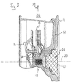
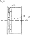
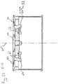
- FIG Figure 2 the installation position of a mechanically driven compressor arrangement 10, as arranged in the above-mentioned wheels 2a and 2b, is shown schematically.
- the compressor assembly 10 itself is shown in FIG Figure 2 shown only schematically by a cross-hatched area.
- a rim bears the reference number 12.
- a brake disk 14, a wheel carrier 16, a wheel hub 18 and a wheel bearing 20 are also shown.
- a first pressure medium line 22 extends from the compressor arrangement 10 to a tire cavity 24.
- the tire itself is in FIG Figure 1 not shown.
- the first pressure medium line 22 extends through the material of the rim 12.
- connection 28 for supplying a sealing agent.
- the connection 28 is optional.
- An axis of rotation bears the reference numeral 30 and a radial direction the reference numeral 32.
- the hub side and thus the hub-side components rotate around the axis of rotation 30 relative to the wheel carrier side, i.e. relative to the wheel carrier-side components such as, for example, relative to the wheel carrier or also relative to the Passenger compartment of the vehicle.
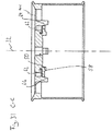
- FIG. 13 shows the installation position of an electrically driven compressor arrangement 10, as arranged in the above-mentioned wheels 2c and 2d, in a representation similar to the representation of FIG Figure 2 shown.
- the electrically driven compressor arrangement 10 is arranged in the area of the wheel hub receptacle 26, preferably in the wheel hub receptacle 26.
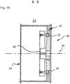
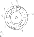
- Figure 4 shows a first embodiment of a vehicle wheel according to the invention in a side view seen from the side of the wheel carrier in detail.
- the rim 12 of the vehicle wheel 2 is shown without the tire.
- the rim 12 comprises a radially outer rim base 36 and a radially inner hub section 38.
- a plurality of spoke-like support sections 40 extend in the radial direction.
- the spoke-like support sections 40 extend from the hub section 38 to the rim well 36.
- the support sections 40 are each spaced apart from one another via intermediate spaces 42.
- a cover element 44 is assigned to each intermediate space 42.
- the cover elements 44 are shown in a first position.
- the vehicle wheel is designed in such a way that in this first position the cover elements 44 cover the spaces 42 in such a way that the spaces 42 are completely closed.
- this complete coverage is not mandatory.
- a dust collecting device 45 is shown symbolically arranged in the interior of the rim 12.
- the dust collecting device 45 can collect dust that is in the air in the inner region 47 of the rim 12 magnetically or via an air filter.
- the rim comprises an actuating device 46.
- the actuating device 46 comprises an annular actuating element 48.
- the annular actuating element 48 is connected to a plurality of actuators 50 which are arranged distributed in a circumferential direction and which likewise form part of the actuating device 46.
- the actuators 50 can be coupled to the brake of the vehicle 1 via a coupling device 51. In this way, the actuation of the actuators 50 can be coupled to the respective driving state of the vehicle 1 or also to the operating state of the brake of the vehicle 1.
- the Coupling device 51 can be coupled or connected to an operating unit for the driver of vehicle 1.
- Such a coupling device 51 can be combined with each of the embodiments of the vehicle wheel 2 described in this application, but does not necessarily see it.
- the actuators 50 are each connected to the tire cavity 24 via pressure medium lines 52.
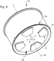
- the Figures 4-8 show the cover elements 44 each in the first position, in which they completely close the spaces 42 in this embodiment.
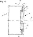
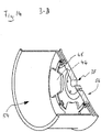
- the Figures 7 , 8th and 10 show the vehicle wheel 2 in each case along the line AA Figure 4 cut.
- the cover elements 44 cover the spaces 42 less than in the first position. More precisely, the cover elements in the embodiment shown are displaced along the axis of rotation 30, viewed from a wheel carrier side 54 of the vehicle wheel 2, to an outer side 56 in FIG. Figure 9 shows a perspective illustration similar to the illustration of FIG Figure 5 and Figure 10 FIG. 4 shows a sectioned illustration similar to the illustration in FIG Figure 7 .
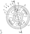
- the actuators 50 each comprise switching units 58, with which the annular actuating element 48 can be displaced by the application of pressure medium.
- the pressurized pressure medium comes from the tire cavity 24.
- the switching units 58 are designed in such a way that the cover elements 44 can be transferred from the first position to the second position and from the second position back to the first position via the annular actuating element 48 via pneumatic actuation. When the direction of movement of the cover elements 44 is switched over in the event of pneumatic actuation via the switching units 58.
- the switching units 58 can be coupled to the brake comprising the brake disc 14 in such a way that, when the brake is actuated, they move the cover element 44 into the second position ( Figures 9 and 10 ) transfer. It is also conceivable that the cover element 44 then moves into the second position ( Figures 9 and 10 ) are transferred by a switching operation of the switching units 58 when a temperature of the brake disc 14 exceeds a certain value.
- the Figures 11-17 show an alternative embodiment of the vehicle wheel 2 according to the invention
- Figures 11-14 show the cover elements 44 in the first position. In this first position, the spaces 42 are completely closed by the cover elements 44.
- the vehicle wheel 2 of this embodiment is shown with the cover elements 44 in the second position. In this second position, the cover elements 44 are displaced in the axial direction, that is to say in the direction of the axis of rotation 30 towards the wheel carrier side 54 of the vehicle wheel 2. As a result, the spaces 42 are each open.
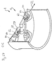
- FIGS 18-25 show a vehicle wheel 2 of a further embodiment.
- the cover elements 44 of the vehicle wheel are each shown in the second position.
- the cover elements 44 are each shown in the first position. In the first position, the cover elements 44 completely close the spaces 42 in the present embodiment.
- the cover elements 44 are tilted relative to the support sections 40, whereby the spaces 42 are opened.
- the cover elements 44 are tilted in such a way that when the vehicle wheel 2 rotates along the direction of rotation indicated by the reference numeral 60, air reaches or is guided via the cover elements 44 to the wheel carrier side 54 of the vehicle wheel 2.
- cover elements 44 In order to be independent of the direction of installation or the direction of travel of the vehicle, the cover elements 44 open or tilt in different directions, which is for example in Figure 18 is clearly visible.
- the cover elements 44 which are arranged diametrically opposite one another, open towards the opposite direction as seen in the circumferential direction.
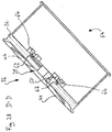
- FIGS 26-31 show a vehicle wheel 2 of a further embodiment.
- the cover elements 44 of the vehicle wheel 2 are each shown in the second position.
- the cover elements 44 are each shown in the first position in which they completely close the spaces 42.
- the cover elements 44 are tilted relative to the support sections 40, whereby the spaces 42 are opened.
- the cover elements 44 are mounted tiltably at their radially inner end.
- this type of tiltable mounting is not mandatory in the embodiment of FIG Figures 18-25 for example the tilt axis runs largely in the radial direction 32. If the cover elements can be moved from the first position to the second position by tilting, the tilt axis can for example run in the radial direction 32, be arranged radially outside on the cover element 44 or radially inside on the cover element 44 be arranged.
- the actuators 50 can be provided with plungers 62, as in FIGS Figures 26-31 be formed shown.
- the plunger 62 of the respective stroke actuator 50 can be extended and retracted in the radial direction 32, and its radially outer end can rest against a contact section 64 of the cover elements 44. If the respective plunger 62 of a cover element 44 is pneumatically moved radially outward in such an arrangement, i.e. if the actuating device 46 is pneumatically actuated, the plunger 62 rests on the respective beveled contact section 64 of the cover element 44 and tilts the cover element 44 radially outward through its directed movement.
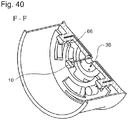
- FIGS 32-40 show an example of vehicle wheel 2 not according to the invention
- Figures 32 , 33 and 34-36 the cover elements 44 of the vehicle wheel 2 are each shown in the first position in which they completely close the spaces 42 in the present case.
- the cover elements 44 are each shown in the second position in which they do not completely close the spaces 42.
- the cover elements 44 of the embodiment of Figures 32-40 are due to a rotational movement in relation to the Support sections 40 movable between the first position and the second position or between the second position and the first position.
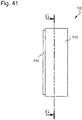
- the cover elements 44 can be designed as a disk-like element 66. Such a disk-like element 66 is shown in FIG Figure 34 shown.
- the disk-like element 66 has slot-like recesses 68.
- the slot-like recesses 68 serve to enable the rotational movement of the disk-like element 66 or the cover elements 44 with respect to the actuators 50, which are fixedly connected to the rim 12.
- the actuators 50 are connected via the tappets 62 to articulation devices 72 which are fixedly connected to the disk-like element 66.
- the actuators 50 can be connected to a compressor arrangement 10. Such a connection between the actuators 50 and a compressor arrangement is shown in FIGS Figures 35 , 36 , 39 and 40 represented symbolically. Pressure medium can be applied to the actuators via the compressor arrangement 10. This enables the cover elements 44 to be actuated pneumatically.
- the compressor arrangement is preferably arranged on the hub side. However, it is also conceivable to connect the actuators 50 via corresponding pressure medium lines with rotary feedthroughs to a vehicle-side compressor device for supplying pressure medium.
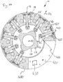
- the compressor arrangement 10 comprises a first housing part 112 and a second housing part 114.
- the compressor arrangement 10 is off Figure 41 shown cut along the line GG.
- the compressor arrangement 10 in the present case comprises a total of four hub-side compression chambers 116, only two of which have a reference number.
- a hub-side compressor component 118 is assigned to each of the compression chambers 116, only two of which also have a reference number.
- the compressor arrangement 10 comprises a plurality of gears 120, a gear 120 being assigned to each of the compression spaces 116.
- the gears 120 are each designed as cam gears 122.
- the gears 120 each have a hub-side gear part 124.
- the hub-side gear parts 124 are each formed by ram drives 125.
- the compressor components 118 are formed in one piece with the tappet drives 125 or gear parts 124 on the hub side.
- the hub-side gear parts 124 of the gears 120 can each interact with a gear carrier-side gear part 126 of the compressor arrangement 10.
- the compressor arrangement 10 has only a single transmission part on the wheel carrier side 126, which can interact with each of the hub-side gear parts 124.
- the gear part 126 on the wheel carrier side is designed as a disk curve 128 with an outer curve contour 130.
- Figure 42 the compressor arrangement 10 is shown in a freewheeling operating position FL.
- the gear parts 124 on the hub side do not interact with the gear part 126 on the wheel carrier side.
- the hub-side gear parts 124 are advantageously in the freewheeling operating position FL, as in FIG Figure 42 shown in a position in which they can not contact this regardless of the orientation of the wheel carrier-side transmission part 126.
- This is achieved via clutch devices 136 which are assigned to each of the gear parts 124 on the hub side.
- the coupling devices 136 each comprise a coupling element 138.
- the clutch elements 138 shown are each in a locked position 140. In this locked position 140 of the clutch element 138, the hub-side gear parts 124 are prevented from interacting and in the present case also from contact with the gear-carrier-side gear part 126.
- a blocking section 142 of the respective coupling elements 138 is in each case on a stop section 144 on the respective hub-side Gear parts 124 on.
- the stop section 144 is formed on the compressor component 118, which is formed in one piece with the hub-side transmission part 124.
- the coupling elements 138 are designed like pins and, in addition to the blocking section 142, also each include a release section 146 and a transition section 148.
- the locking section 142 is cylindrical with a first diameter and the release section 146 is cylindrical with a second diameter.
- the transition section 148 from the locking section 142 to the release section 146 has a truncated cone shape.
- the release section 146 is arranged offset in the direction of the radial direction 134 with respect to the blocking section 142. If one of the coupling elements 138 moves from the release position into the blocking position 140, it forces the hub-side gear part 124 assigned to it into the position in which it cannot come into contact with the gear part 126 on the wheel carrier side.
- the coupling elements 138 are each biased into the blocking position via springs 149. Via a pressure medium channel 156, the coupling elements 138 can each be transferred into the release position by applying pressure medium.
- the hub-side gear parts 124 and the compressor components 118 are thereby pushed radially outward, namely into a position in which they lift off the radially inner gear part 126 on the wheel carrier side.
- the compressor arrangement 10 is then in the freewheeling position FL.
- the conical transition section 148 enables the hub-side gear part 124 to be pushed radially outward and the transition from the release position to the blocking position takes place smoothly and gradually.
- the springs 149 for preloading the coupling elements 138 must be made stronger than the springs for preloading the hub-side gear parts 124. This preload, in conjunction with the conical transition section 148, enables the hub-side gear parts 124 to be pushed into the lifted position ( Figure 42 ).
- FIG. 13 shows another embodiment of a mechanical compressor arrangement 10 similar to the embodiment of FIG Figures 41 to 43 the compressor components 118 are designed to carry out an oscillating translational movement in the radial direction.
- the representation is a sectional view similar to that Figures 42 and 43 .
- the gear parts 124 on the hub side are designed as roller tappets 400. At their end facing the gear part 126 on the wheel carrier side, they each have a self-lubricating roller 410.
- Flutter valves 440 are arranged on each of the compressor components 18. Double seals 450 are also arranged on the compressor components 118, each delimiting a lubricant reservoir 460 of the compressor component 118 and at the same time sealing the compression chamber 116 against the compressor component 118.
- the compressor arrangement 10 also comprises an area 420 which is used, for example, to accommodate a control device, a filter, a clutch valve or a relief valve.
- an energy source 430 can be arranged there, which can be designed, for example, as an accumulator or also as a pressure accumulator.
- a hub-side part 470 of the compressor arrangement 10 is largely ring-shaped and in the present case includes all of FIG Figure 44 shown parts of the compressor arrangement 10 except for the gear carrier-side gear part 126.
- Figures 45 to 47 show a further possibility for implementing the mechanical compressor arrangement 10.
- the compressor arrangement 10 is shown cut along the line HH.
- the compressor arrangement comprises a first housing part 230 on the hub side and a second housing part 232 on the hub side.
- Gear parts on the hub side have the reference numeral 234.
- Figure 3 two of the hub-side gear parts 234 of the compressor arrangement 10 can be seen.
- the compressor component 238 in the form of the annular piston 236 delimits a first compression space 240 and a second compression space 242.
- the hub-side gear elements 234 are in the Figure 3 and 4th operating position shown, with a gear carrier-side gear part 244 in such engagement that they can interact with them.
- the hub-side gear parts 234 each have a first actuatable contact element 246 and a second stationary contact element 248.
- the contact elements 246, 248 of the respective hub-side gear parts 234 are in contact with a bead cylinder curve 250 of the wheel-carrier-side gear part 244, whereby the hub-side gear part 234 interacts with the wheel carrier-side gear part 244.
- first contact elements 246 can be actuated. This is evident in Figure 47 evident.
- the hub-side gear parts 234 can be brought into cooperation with the gear-carrier-side gear part 244. If the actuation of the clutch device 254 is interrupted, an interaction of the hub-side gear parts 234 with the wheel-carrier-side gear part 244 can be prevented.
- the first actuatable contact elements 246 do not contact the cylinder bead curve 250 of the gear part 244 on the wheel carrier side.
- the hub-side gear parts 234 are thus prevented from interacting with the gear carrier-side gear part 244.
- the first actuatable contact elements 246 are designed in the manner of a piston and move in the direction of the bead cylinder disk 250 when pressure medium is applied and contact them. This state is in Figure 46 and 47 shown.
- the first actuatable contact elements 246 are preloaded via compression springs 256 in such a way that they transfer the compressor arrangement 10 into a free-running operating position when the pressure spaces 252 are not acted upon by pressure medium.
- the coupling device 254 is therefore pretensioned in a non-actuated position.
- the inlets 266 of the pressure chambers 252 are each connected to the tire cavity 24 via a section 268 of a pressure medium line 222 via a valve 270, which forms a coupling valve.
- the clutch valve 270 is designed such that it opens when the pressure in the tire falls below a pressure threshold value.
- the pressure spaces 252 are then acted upon with pressure medium from the tire cavity 24.
- the first actuatable contact elements 246 are then moved against the bias of the springs 256 in the direction of the cylinder bead curve 250 and contact them.
- the oscillatory translational movement of the compressor component 238 or the annular piston 236 is thus generated by the rotational relative movement between the gear carrier-side gear part 244 and the hub-side gear part 234 and the interaction of the two gear parts.
- the oscillatory translational movement of the compressor component 238 alternately reduces the volumes of the compression chambers 240 and 242, as a result of which pressure medium is conveyed from these to the tire cavity 24.
- the pressure chambers 240 and 242 are connected to the tire cavity 24 via a check valve 272.
- the check valve 272 opens towards the tire cavity 24.
- the coupling valve 270 closes and the line section 268 between the coupling valve 270 and the pressure chambers 252 is vented via a relief valve 274.
- the actuatable contact elements 246 move away from the cylinder bead curve 250 into the FIG Figure 48 position shown.
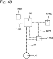
- the compressor assembly 10 may generally be connected to a filter 1200 and a controller 1210.
- the filter 1200 is preferably arranged in such a way that it is arranged fluidically in front of the pressure medium inlets or air inlets of the compressor arrangement 10.
- the control device 1210 can detect via a measuring connection 1220 when the filter 1200 is clogged. If a blockage of the filter 1200 is detected by the control device 1210, the filter can be cleaned by applying pressure medium or air to it in the opposite direction of flow.
- air is conveyed via the filter 1200 in the direction of the compressor arrangement 10 and from there to the tire cavity 24.
- pressure medium or air is either released from the tire cavity 24 and conveyed through the filter 1200 in the opposite direction of flow, or the compressor arrangement 10 starts operating and conveys pressure medium to the filter 1200 instead of to the tire cavity 24 in the opposite direction of flow.
- the compressor arrangement 10 sucks Pressure medium over a an additional inlet 1230, which has a further air filter 1240, which can be cleaned in a similar manner.
- the control device 1210 can advantageously serve to measure and / or display the pressure, the temperature and / or the humidity of the pressure medium in the tire cavity 24, these functions being independent of the other functions of the control device 1210.
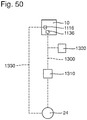
- FIG 50 an exemplary variant of the control of the clutch device 1136 is shown.
- the actuation of the clutch device 1136 can, however, also take place electrically, electromagnetically or electromechanically.
- electrical energy can be fed from the main battery 3 of the vehicle 1 or from a generator provided there or from another energy source via sliding contacts to the hub side.
- the compressor arrangement 10 in particular its clutch device 1136, is connected to the tire cavity 24 via a clutch pressure medium line 1300 connected.
- a clutch valve 1310 is arranged in the clutch pressure medium line 1300.
- a relief valve 1320 is also provided on the clutch pressure medium line 1300.
- the compression chambers 1116 of the compressor arrangement 10 are connected to the tire cavity 24 via a pressure medium line 1330 provided for delivery.
- the pressure medium of the tire cavity 24 is applied to the clutch valve 1310 under the pressure prevailing in the tire.
- the clutch valve 1310 opens, whereby the clutch device 1136 is actuated by means of pressure medium from the tire cavity 24 and the hub-side transmission part 124, 234 is brought into cooperation with the wheel-carrier-side transmission part 126, 244.
- pressure medium is conveyed from the compression spaces 1116 to the tire cavity 24 via the pressure medium line 1330 provided for conveyance.
- the clutch pressure medium line 1300 and the pressure medium line 1330 provided for delivery can also be designed together as a single line.
- the clutch valve 1310 closes, whereby the Pressurizing the clutch device 1136 with pressure medium is interrupted.
- the clutch device 1136 is preferably vented via the clutch valve 1310 or the relief valve 1320 when the tire pressure setpoint is exceeded. This ensures that the compressor arrangement 10 stops operating immediately as soon as a pressure medium setpoint value is reached in the tire cavity 24.
- This operating mode of the coupling device 1136 can be combined with all embodiments and individual aspects of these embodiments of the compressor arrangement 10 of this application.
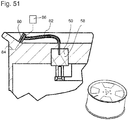
- Figure 51 shows a possibility of providing pressure medium for actuating the cover element 44.
- the tire cavity can be filled with pressure medium via a valve 80.
- a branch 82 leads from the valve 80 to the actuator 50.
- Another branch 84 leads to the tire cavity 24. If a pressure medium source is connected to the valve 80, the tire cavity 24 can be filled with pressure medium via the further branch 84.
- the pressure medium is present in branch 82 with the pressure prevailing in the tire cavity and can be switched via the switching units 58.
- the valve 80 can also include a control unit 86 with which the pressure medium can be switched in such a way that the cover element 44 either opens or closes.
- the actuation device 46 of a vehicle wheel 2 can have two types of actuators 50a, 50b.
- the actuators 50a of the first type lead to an opening of the cover elements 44 when pressure medium is applied, and the actuators 50b of the second type lead to a closure of the cover element 44 when pressure medium is applied.
- actuators 50 of various types can be combined with all types of vehicle wheels described in this application.
- a central switching unit can apply pressure medium to various pressure medium lines, depending on which type of actuator is to be controlled.
Landscapes
- Engineering & Computer Science (AREA)
- Mechanical Engineering (AREA)
- Arrangement Or Mounting Of Propulsion Units For Vehicles (AREA)
- Valves And Accessory Devices For Braking Systems (AREA)
- Hydraulic Clutches, Magnetic Clutches, Fluid Clutches, And Fluid Joints (AREA)
- Tires In General (AREA)
Claims (19)
- Roue de véhicule comprenant une jante (12) qui présente une section de moyeu (38), une base de jante (36) destinée à recevoir un pneu, plusieurs sections de support (40) disposées entre la section de moyeu (38) et la base de jante (36), au moins un espace intermédiaire ménagé entre les sections de support (40), et au moins un élément de recouvrement associé à l'espace intermédiaire (42), ledit élément de recouvrement pouvant passer d'une première position à une seconde position par actionnement pneumatique,
caractérisée en ce qu'un dispositif d'actionnement (46) destiné à l'actionnement pneumatique de l'élément de recouvrement (44) peut être actionné par pression provenant d'une cavité de pneu (24) de la roue de véhicule (2). - Roue de véhicule selon la revendication 1, caractérisée en ce qu'un canal de pression (52) s'étend de la cavité de pneu (24) jusqu'au dispositif d'actionnement (46) de l'élément de recouvrement (44), en particulier le canal de pression (52) s'étend au moins à certains endroits, de préférence entièrement dans le matériau de la jante (12), de préférence dans le matériau d'une des sections de support (40).
- Roue de véhicule selon l'une ou plusieurs revendications précédentes, caractérisée en ce qu'elle comprend un système compresseur (10) destiné à fournir un moyen de pression se trouvant sous pression.
- Roue de véhicule selon la revendication précédente, caractérisée en ce que le système compresseur (10) comprend au moins un espace de compression (116, 240, 242) côté moyeu.
- Roue de véhicule selon l'une des deux revendications précédentes, caractérisée en ce que le système compresseur (10) comprend un composant de compresseur (118, 238) et le moyen de pression peut être mis sous pression par un mouvement de préférence translatoire, du compressant de compresseur (118, 238).
- Roue de véhicule selon la revendication précédente, caractérisée en ce qu'elle peut être montée en rotation autour d'un axe de rotation (30) sur un support de roue (16), et le système de compresseur (10) comprend un entraînement (120), de préférence un entraînement par cames (122) qui est conçu pour transformer par l'interaction entre une partie d'entraînement (126, 244) côté support de roue et une partie d'entraînement (124, 234) côté moyeu un mouvement de rotation entre le côté de support de roue et le côté moyeu en un mouvement de préférence oscillatoire translatoire du composant de compresseur (118, 238).
- Roue de véhicule selon l'une ou plusieurs revendications précédentes 3 à 5, caractérisée en ce que le système compresseur (10) est entraîné électriquement.
- Roue de véhicule selon la revendication 7, caractérisée en ce qu'elle comprend un dispositif de transfert d'énergie (6), de préférence, sans contact, qui permet de transférer l'énergie électrique servant au fonctionnement du système compresseur (10) depuis une source d'énergie côté roue (3) vers le système compresseur (10).
- Roue de véhicule selon la revendication 7 ou la revendication 8 caractérisée en ce qu'elle comprend une source d'énergie (7, 8) côté moyeu pour fournir de l'énergie électrique pour le fonctionnement du système compresseur (10).
- Roue de véhicule selon la revendication 9, caractérisé en ce que la source d'énergie côté moyeu (7, 8) comprend un producteur d'énergie (8) qui permet de convertir le mouvement de rotation entre le côté support de roue et le côté moyeu de roue en énergie électrique.
- Roue de véhicule selon l'une quelconque ou plusieurs revendications précédentes, caractérisée en ce que l'élément de recouvrement (44) recouvre davantage l'espace intermédiaire (42) dans la première position de l'élément de recouvrement (44) que dans la seconde position de l'élément de recouvrement (44), de préférence en ce que l'élément de recouvrement (44) referme en grande partie l'espace intermédiaire (42) dans la première position de l'élément de recouvrement (44).
- Roue de véhicule selon l'une quelconque ou plusieurs revendications précédentes caractérisée en ce que l'élément de recouvrement (44) est précontraint dans une position, de préférence dans la première position,
et/ou en ce que l'élément de recouvrement (44) peut être déplacé par un mouvement de rotation par rapport aux sections de support (40) entre la première position et la seconde position,
et/ou en ce que l'élément de recouvrement (44) peut être déplacé par un mouvement, de préférence exclusivement, de translation dans la direction de l'axe de rotation (30) par rapport aux sections de support (40) entre la première position et la seconde position. - Roue de véhicule selon l'une quelconque ou plusieurs revendications précédentes, caractérisée en ce que l'élément de recouvrement (44) peut être déplacé par un mouvement de basculement entre la première position et la seconde position par rapport aux sections de support (40).
- Roue de véhicule selon l'une quelconque ou plusieurs revendications précédentes, caractérisée en ce qu'elle présente plusieurs espaces intermédiaires (42) qui sont respectivement associés à un élément de recouvrement (44), qui peut passer d'une première position à une seconde position par actionnement pneumatique.
- Roue de véhicule selon l'une quelconque ou plusieurs revendications précédentes, caractérisée en ce qu'elle présente un dispositif d'accouplement qui permet d'accoupler l'élément de recouvrement (44) à un frein du véhicule (1), dans lequel est montée la roue de véhicule (2), le dispositif d'accouplement (51) étant conçu pour commander un dispositif d'actionnement (46) de l'élément de recouvrement (44) de telle sorte que l'élément de recouvrement (44) puisse passer de la première position à la seconde position, en fonction de l'actionnement du frein et/ou en cas de dépassement d'un seuil de température dans la zone des freins.
- Roue de véhicule selon l'une quelconque ou plusieurs revendications précédentes, caractérisée en ce que l'élément de recouvrement (44) peut passer de la première à la seconde position de manière échelonnée en passant par des positions intermédiaires,
et/ou en ce que l'élément de recouvrement (44) est disposé dans la seconde position de telle sorte par rapport à l'élément de support (40) qu'il guide de l'air en direction du système de freinage lorsque la roue de véhicule (2) tourne par rotation de la roue du véhicule (2). - Roue de véhicule selon l'une quelconque ou plusieurs revendications précédentes, caractérisée en ce qu'elle comprend un dispositif de collecte de poussière (45) qui est conçu pour collecter les particules de poussière provenant de l'air présent à l'intérieur de la jante (12).
- Roue de véhicule selon l'une revendication précédente, caractérisée en ce que le dispositif de collecte de poussière (45) comprend un filtre à air et/ou un collecteur de poussière magnétique.
- Roue de véhicule selon l'une quelconque ou plusieurs revendications précédentes, caractérisée en ce que la position de l'élément de recouvrement (44) peut être prédéfinie par une partie de commutation (58), de préférence en fonction de la vitesse du véhicule (1) et/ou en fonction de l'état de fonctionnement du frein du véhicule (1).
Applications Claiming Priority (2)
| Application Number | Priority Date | Filing Date | Title |
|---|---|---|---|
| DE102016124121.0A DE102016124121B4 (de) | 2016-12-13 | 2016-12-13 | Fahrzeugrad |
| PCT/EP2017/082675 WO2018109032A2 (fr) | 2016-12-13 | 2017-12-13 | Roue de véhicule |
Publications (2)
| Publication Number | Publication Date |
|---|---|
| EP3554847A2 EP3554847A2 (fr) | 2019-10-23 |
| EP3554847B1 true EP3554847B1 (fr) | 2020-11-25 |
Family
ID=61157149
Family Applications (1)
| Application Number | Title | Priority Date | Filing Date |
|---|---|---|---|
| EP17838036.6A Active EP3554847B1 (fr) | 2016-12-13 | 2017-12-13 | Roue de véhicule |
Country Status (7)
| Country | Link |
|---|---|
| US (1) | US11364739B2 (fr) |
| EP (1) | EP3554847B1 (fr) |
| JP (1) | JP7088601B2 (fr) |
| CN (1) | CN110325376B (fr) |
| DE (1) | DE102016124121B4 (fr) |
| ES (1) | ES2842588T3 (fr) |
| WO (1) | WO2018109032A2 (fr) |
Families Citing this family (7)
| Publication number | Priority date | Publication date | Assignee | Title |
|---|---|---|---|---|
| CN110682728B (zh) * | 2018-07-06 | 2021-05-14 | 广州汽车集团股份有限公司 | 一种汽车轮毂散热方法及其装置、汽车 |
| KR102663606B1 (ko) * | 2019-04-23 | 2024-05-08 | 현대자동차주식회사 | 공력가변 휠 및 공력가변 휠 제어 시스템 |
| AT524701B1 (de) * | 2021-01-29 | 2022-10-15 | Avl List Gmbh | Messfelge zum Sammeln von Bremsabrieb |
| DE102022102999B4 (de) * | 2022-02-09 | 2024-02-08 | Kt Projektentwicklungs-Gmbh | Felge für ein Fahrzeugrad, Fahrzeugrad und Fahrzeug mit einem solchen Fahrzeugrad |
| DE102022126514B4 (de) | 2022-10-12 | 2024-09-05 | Dr. Ing. H.C. F. Porsche Aktiengesellschaft | Zierblende für ein Fahrzeugrad, Fahrzeugrad und Kraftfahrzeug |
| CN116181609A (zh) * | 2023-04-10 | 2023-05-30 | 罗浩文 | 交通工具用空气压缩装置 |
| CN119239168B (zh) * | 2024-12-02 | 2025-12-16 | 浙江吉利控股集团有限公司 | 车轮系统和车辆 |
Family Cites Families (19)
| Publication number | Priority date | Publication date | Assignee | Title |
|---|---|---|---|---|
| US2506677A (en) * | 1944-09-28 | 1950-05-09 | Mckenna Denis | Vehicle wheel |
| US7100995B2 (en) * | 2003-09-08 | 2006-09-05 | Gls Wheels, L.L.C. | Wheel spinner assembly |
| FR2886214B1 (fr) | 2005-05-31 | 2009-01-09 | Peugeot Citroen Automobiles Sa | Jante pour vehicule automobile |
| US7661766B2 (en) * | 2006-08-14 | 2010-02-16 | Davis Jon R | Rim assembly with oscillator |
| JP2009126423A (ja) * | 2007-11-26 | 2009-06-11 | Toyota Motor Corp | ブレーキ保護装置 |
| DE102008007690A1 (de) * | 2008-02-06 | 2009-08-13 | GM Global Technology Operations, Inc., Detroit | Felge oder Radanbauteil für ein Kraftfahrzeugrad mit verschließbaren Öffnungen |
| DE102009037803A1 (de) * | 2009-02-10 | 2010-08-12 | Kt Projektentwicklungs-Gmbh | Vorrichtung zur Einstellung des Gasdrucks in einem Kraftfahrzeugreifen |
| DE102009031879A1 (de) * | 2009-07-06 | 2011-01-13 | Wilhelm Roth | A.F.B Anfahr-Fahr-Bremshilfe |
| DE102011010509A1 (de) * | 2011-02-07 | 2012-08-09 | Audi Ag | Fahrzeugrad |
| DE102012016834B4 (de) * | 2012-08-27 | 2022-05-19 | Mann+Hummel Gmbh | Bremsstaubaufnahmevorrichtung für Kraftfahrzeuge und Filterelement |
| KR101459922B1 (ko) * | 2013-06-26 | 2014-11-07 | 현대자동차주식회사 | 무선전력 전송 기능을 가지는 차량 구동 시스템 및 그 방법 |
| MX2017000350A (es) | 2014-07-10 | 2017-08-14 | Zanini Auto Grup Sa | Tapacubos. |
| DE102014017517B3 (de) * | 2014-11-27 | 2016-03-03 | Audi Ag | Reinigungseinrichtung für eine Sensoreneinheit eines Kraftfahrzeugs |
| GB2540137A (en) * | 2015-07-02 | 2017-01-11 | Nissan Motor Mfg (Uk) Ltd | Wheel assembly |
| DE102015120134A1 (de) * | 2015-11-20 | 2017-05-24 | Bpw Bergische Achsen Kg | Reifenbefüllvorrichtung für ein Fahrzeugrad |
| DE102016003963A1 (de) | 2016-04-01 | 2016-09-29 | Daimler Ag | Abdeckeinrichtung für eine Felge eines Kraftwagens |
| DE102016013286A1 (de) | 2016-11-08 | 2017-05-24 | Daimler Ag | Fahrzeugrad |
| DE102017009746A1 (de) * | 2017-10-14 | 2019-04-18 | Gv Engineering Gmbh | Aerodynamische Felge |
| US20190322128A1 (en) * | 2018-04-18 | 2019-10-24 | GM Global Technology Operations LLC | Vehicle wheel assembly including a self-deployed wheel shutter system |
-
2016
- 2016-12-13 DE DE102016124121.0A patent/DE102016124121B4/de active Active
-
2017
- 2017-12-13 CN CN201780086215.1A patent/CN110325376B/zh active Active
- 2017-12-13 WO PCT/EP2017/082675 patent/WO2018109032A2/fr not_active Ceased
- 2017-12-13 JP JP2019532711A patent/JP7088601B2/ja active Active
- 2017-12-13 EP EP17838036.6A patent/EP3554847B1/fr active Active
- 2017-12-13 US US16/468,755 patent/US11364739B2/en active Active
- 2017-12-13 ES ES17838036T patent/ES2842588T3/es active Active
Non-Patent Citations (1)
| Title |
|---|
| None * |
Also Published As
| Publication number | Publication date |
|---|---|
| CN110325376A (zh) | 2019-10-11 |
| DE102016124121A1 (de) | 2018-06-14 |
| JP2020513377A (ja) | 2020-05-14 |
| ES2842588T3 (es) | 2021-07-14 |
| JP7088601B2 (ja) | 2022-06-21 |
| CN110325376B (zh) | 2023-03-24 |
| US20200223248A1 (en) | 2020-07-16 |
| WO2018109032A3 (fr) | 2018-08-16 |
| WO2018109032A2 (fr) | 2018-06-21 |
| US11364739B2 (en) | 2022-06-21 |
| EP3554847A2 (fr) | 2019-10-23 |
| DE102016124121B4 (de) | 2025-01-16 |
Similar Documents
| Publication | Publication Date | Title |
|---|---|---|
| EP3554847B1 (fr) | Roue de véhicule | |
| EP3694727B1 (fr) | Jante aérodynamique | |
| EP3544831B1 (fr) | Ensemble compresseur à pistons radiaux | |
| EP3544830B1 (fr) | Véhicule automobile comprenant un ensemble compresseur | |
| EP3544832B1 (fr) | Ensemble compresseur | |
| EP3544833B1 (fr) | Ensemble compresseur comprenant une came cylindrique de talon | |
| EP3544834B1 (fr) | Véhicule équipé d'un ensemble compresseur | |
| DE102022000035A1 (de) | Radnabenantrieb für ein Kraftfahrzeug, insbesondere für einen Kraftwagen, sowie Kraftfahrzeug | |
| DE102009021300A1 (de) | Rotationsarretierung für ein um eine Achse drehbares Bauteil | |
| DE4209372B4 (de) | Hydraulische Bremseinrichtung für Fahrzeuge | |
| DE2508771A1 (de) | Druckmittelbetaetigte scheibenbremse, insbesondere fuer kraftfahrzeuge | |
| EP3589505B1 (fr) | Ensemble compresseur avec accouplement magnétique | |
| DE102022123640B4 (de) | Bremsvorrichtung und elektrisch betreibbarer Achsantriebsstrang eines Kraftfahrzeugs | |
| DE102008011338A1 (de) | Automatisches Schaltgetriebe mit abbremsbarer Planeteneinheit | |
| WO2008019824A1 (fr) | Dispositif et procédé de modification automatique de la pression d'un pneumatique d'une roue de véhicule | |
| DE102018130819A1 (de) | Elektrische Achsantriebseinheit mit integrierter Bremseinrichtung | |
| EP2923099A1 (fr) | Système de débrayage | |
| WO2023126236A1 (fr) | Entraînement de moyeu de roue pour un véhicule automobile, notamment pour une automobile, et véhicule automobile | |
| DE102016010055B3 (de) | Verdichteranordnung zur Druckmittelversorgung eines Reifens | |
| DE102023104828A1 (de) | Bremsvorrichtung ausgebildet zur Rückgewinnung thermischer Energie; sowie Kraftfahrzeug | |
| EP0684916A1 (fr) | Systeme de freinage pour vehicule sur rails, en particulier pour locomotive, et vehicule sur rails muni d'un tel systeme de freinage | |
| DE102015207850A1 (de) | Hydrodynamischer Retarder | |
| DE102011118798A1 (de) | Bremsscheibenanordnung | |
| DE102006009724A1 (de) | Bremsaktuator für Scheibenbremsen |
Legal Events
| Date | Code | Title | Description |
|---|---|---|---|
| STAA | Information on the status of an ep patent application or granted ep patent |
Free format text: STATUS: UNKNOWN |
|
| STAA | Information on the status of an ep patent application or granted ep patent |
Free format text: STATUS: THE INTERNATIONAL PUBLICATION HAS BEEN MADE |
|
| PUAI | Public reference made under article 153(3) epc to a published international application that has entered the european phase |
Free format text: ORIGINAL CODE: 0009012 |
|
| STAA | Information on the status of an ep patent application or granted ep patent |
Free format text: STATUS: REQUEST FOR EXAMINATION WAS MADE |
|
| 17P | Request for examination filed |
Effective date: 20190711 |
|
| AK | Designated contracting states |
Kind code of ref document: A2 Designated state(s): AL AT BE BG CH CY CZ DE DK EE ES FI FR GB GR HR HU IE IS IT LI LT LU LV MC MK MT NL NO PL PT RO RS SE SI SK SM TR |
|
| AX | Request for extension of the european patent |
Extension state: BA ME |
|
| DAV | Request for validation of the european patent (deleted) | ||
| DAX | Request for extension of the european patent (deleted) | ||
| GRAP | Despatch of communication of intention to grant a patent |
Free format text: ORIGINAL CODE: EPIDOSNIGR1 |
|
| STAA | Information on the status of an ep patent application or granted ep patent |
Free format text: STATUS: GRANT OF PATENT IS INTENDED |
|
| INTG | Intention to grant announced |
Effective date: 20200618 |
|
| GRAS | Grant fee paid |
Free format text: ORIGINAL CODE: EPIDOSNIGR3 |
|
| GRAA | (expected) grant |
Free format text: ORIGINAL CODE: 0009210 |
|
| STAA | Information on the status of an ep patent application or granted ep patent |
Free format text: STATUS: THE PATENT HAS BEEN GRANTED |
|
| REG | Reference to a national code |
Ref country code: DE Ref legal event code: R082 Ref document number: 502017008413 Country of ref document: DE Representative=s name: WUESTHOFF & WUESTHOFF, PATENTANWAELTE PARTG MB, DE |
|
| AK | Designated contracting states |
Kind code of ref document: B1 Designated state(s): AL AT BE BG CH CY CZ DE DK EE ES FI FR GB GR HR HU IE IS IT LI LT LU LV MC MK MT NL NO PL PT RO RS SE SI SK SM TR |
|
| REG | Reference to a national code |
Ref country code: GB Ref legal event code: FG4D Free format text: NOT ENGLISH |
|
| REG | Reference to a national code |
Ref country code: CH Ref legal event code: EP |
|
| REG | Reference to a national code |
Ref country code: DE Ref legal event code: R096 Ref document number: 502017008413 Country of ref document: DE |
|
| REG | Reference to a national code |
Ref country code: AT Ref legal event code: REF Ref document number: 1337862 Country of ref document: AT Kind code of ref document: T Effective date: 20201215 |
|
| REG | Reference to a national code |
Ref country code: IE Ref legal event code: FG4D Free format text: LANGUAGE OF EP DOCUMENT: GERMAN |
|
| REG | Reference to a national code |
Ref country code: NL Ref legal event code: MP Effective date: 20201125 |
|
| PG25 | Lapsed in a contracting state [announced via postgrant information from national office to epo] |
Ref country code: FI Free format text: LAPSE BECAUSE OF FAILURE TO SUBMIT A TRANSLATION OF THE DESCRIPTION OR TO PAY THE FEE WITHIN THE PRESCRIBED TIME-LIMIT Effective date: 20201125 Ref country code: PT Free format text: LAPSE BECAUSE OF FAILURE TO SUBMIT A TRANSLATION OF THE DESCRIPTION OR TO PAY THE FEE WITHIN THE PRESCRIBED TIME-LIMIT Effective date: 20210325 Ref country code: RS Free format text: LAPSE BECAUSE OF FAILURE TO SUBMIT A TRANSLATION OF THE DESCRIPTION OR TO PAY THE FEE WITHIN THE PRESCRIBED TIME-LIMIT Effective date: 20201125 Ref country code: GR Free format text: LAPSE BECAUSE OF FAILURE TO SUBMIT A TRANSLATION OF THE DESCRIPTION OR TO PAY THE FEE WITHIN THE PRESCRIBED TIME-LIMIT Effective date: 20210226 Ref country code: NO Free format text: LAPSE BECAUSE OF FAILURE TO SUBMIT A TRANSLATION OF THE DESCRIPTION OR TO PAY THE FEE WITHIN THE PRESCRIBED TIME-LIMIT Effective date: 20210225 |
|
| PG25 | Lapsed in a contracting state [announced via postgrant information from national office to epo] |
Ref country code: BG Free format text: LAPSE BECAUSE OF FAILURE TO SUBMIT A TRANSLATION OF THE DESCRIPTION OR TO PAY THE FEE WITHIN THE PRESCRIBED TIME-LIMIT Effective date: 20210225 Ref country code: SE Free format text: LAPSE BECAUSE OF FAILURE TO SUBMIT A TRANSLATION OF THE DESCRIPTION OR TO PAY THE FEE WITHIN THE PRESCRIBED TIME-LIMIT Effective date: 20201125 Ref country code: IS Free format text: LAPSE BECAUSE OF FAILURE TO SUBMIT A TRANSLATION OF THE DESCRIPTION OR TO PAY THE FEE WITHIN THE PRESCRIBED TIME-LIMIT Effective date: 20210325 Ref country code: PL Free format text: LAPSE BECAUSE OF FAILURE TO SUBMIT A TRANSLATION OF THE DESCRIPTION OR TO PAY THE FEE WITHIN THE PRESCRIBED TIME-LIMIT Effective date: 20201125 Ref country code: LV Free format text: LAPSE BECAUSE OF FAILURE TO SUBMIT A TRANSLATION OF THE DESCRIPTION OR TO PAY THE FEE WITHIN THE PRESCRIBED TIME-LIMIT Effective date: 20201125 |
|
| REG | Reference to a national code |
Ref country code: LT Ref legal event code: MG9D |
|
| PG25 | Lapsed in a contracting state [announced via postgrant information from national office to epo] |
Ref country code: HR Free format text: LAPSE BECAUSE OF FAILURE TO SUBMIT A TRANSLATION OF THE DESCRIPTION OR TO PAY THE FEE WITHIN THE PRESCRIBED TIME-LIMIT Effective date: 20201125 |
|
| REG | Reference to a national code |
Ref country code: ES Ref legal event code: FG2A Ref document number: 2842588 Country of ref document: ES Kind code of ref document: T3 Effective date: 20210714 |
|
| PG25 | Lapsed in a contracting state [announced via postgrant information from national office to epo] |
Ref country code: RO Free format text: LAPSE BECAUSE OF FAILURE TO SUBMIT A TRANSLATION OF THE DESCRIPTION OR TO PAY THE FEE WITHIN THE PRESCRIBED TIME-LIMIT Effective date: 20201125 Ref country code: SK Free format text: LAPSE BECAUSE OF FAILURE TO SUBMIT A TRANSLATION OF THE DESCRIPTION OR TO PAY THE FEE WITHIN THE PRESCRIBED TIME-LIMIT Effective date: 20201125 Ref country code: SM Free format text: LAPSE BECAUSE OF FAILURE TO SUBMIT A TRANSLATION OF THE DESCRIPTION OR TO PAY THE FEE WITHIN THE PRESCRIBED TIME-LIMIT Effective date: 20201125 Ref country code: CZ Free format text: LAPSE BECAUSE OF FAILURE TO SUBMIT A TRANSLATION OF THE DESCRIPTION OR TO PAY THE FEE WITHIN THE PRESCRIBED TIME-LIMIT Effective date: 20201125 Ref country code: EE Free format text: LAPSE BECAUSE OF FAILURE TO SUBMIT A TRANSLATION OF THE DESCRIPTION OR TO PAY THE FEE WITHIN THE PRESCRIBED TIME-LIMIT Effective date: 20201125 Ref country code: LT Free format text: LAPSE BECAUSE OF FAILURE TO SUBMIT A TRANSLATION OF THE DESCRIPTION OR TO PAY THE FEE WITHIN THE PRESCRIBED TIME-LIMIT Effective date: 20201125 |
|
| REG | Reference to a national code |
Ref country code: CH Ref legal event code: PL |
|
| REG | Reference to a national code |
Ref country code: DE Ref legal event code: R097 Ref document number: 502017008413 Country of ref document: DE |
|
| PG25 | Lapsed in a contracting state [announced via postgrant information from national office to epo] |
Ref country code: DK Free format text: LAPSE BECAUSE OF FAILURE TO SUBMIT A TRANSLATION OF THE DESCRIPTION OR TO PAY THE FEE WITHIN THE PRESCRIBED TIME-LIMIT Effective date: 20201125 Ref country code: MC Free format text: LAPSE BECAUSE OF FAILURE TO SUBMIT A TRANSLATION OF THE DESCRIPTION OR TO PAY THE FEE WITHIN THE PRESCRIBED TIME-LIMIT Effective date: 20201125 |
|
| REG | Reference to a national code |
Ref country code: BE Ref legal event code: MM Effective date: 20201231 |
|
| PLBE | No opposition filed within time limit |
Free format text: ORIGINAL CODE: 0009261 |
|
| STAA | Information on the status of an ep patent application or granted ep patent |
Free format text: STATUS: NO OPPOSITION FILED WITHIN TIME LIMIT |
|
| PG25 | Lapsed in a contracting state [announced via postgrant information from national office to epo] |
Ref country code: IE Free format text: LAPSE BECAUSE OF NON-PAYMENT OF DUE FEES Effective date: 20201213 Ref country code: AL Free format text: LAPSE BECAUSE OF FAILURE TO SUBMIT A TRANSLATION OF THE DESCRIPTION OR TO PAY THE FEE WITHIN THE PRESCRIBED TIME-LIMIT Effective date: 20201125 Ref country code: NL Free format text: LAPSE BECAUSE OF FAILURE TO SUBMIT A TRANSLATION OF THE DESCRIPTION OR TO PAY THE FEE WITHIN THE PRESCRIBED TIME-LIMIT Effective date: 20201125 Ref country code: LU Free format text: LAPSE BECAUSE OF NON-PAYMENT OF DUE FEES Effective date: 20201213 |
|
| 26N | No opposition filed |
Effective date: 20210826 |
|
| PG25 | Lapsed in a contracting state [announced via postgrant information from national office to epo] |
Ref country code: LI Free format text: LAPSE BECAUSE OF NON-PAYMENT OF DUE FEES Effective date: 20201231 Ref country code: CH Free format text: LAPSE BECAUSE OF NON-PAYMENT OF DUE FEES Effective date: 20201231 Ref country code: SI Free format text: LAPSE BECAUSE OF FAILURE TO SUBMIT A TRANSLATION OF THE DESCRIPTION OR TO PAY THE FEE WITHIN THE PRESCRIBED TIME-LIMIT Effective date: 20201125 |
|
| PG25 | Lapsed in a contracting state [announced via postgrant information from national office to epo] |
Ref country code: IS Free format text: LAPSE BECAUSE OF FAILURE TO SUBMIT A TRANSLATION OF THE DESCRIPTION OR TO PAY THE FEE WITHIN THE PRESCRIBED TIME-LIMIT Effective date: 20210325 Ref country code: TR Free format text: LAPSE BECAUSE OF FAILURE TO SUBMIT A TRANSLATION OF THE DESCRIPTION OR TO PAY THE FEE WITHIN THE PRESCRIBED TIME-LIMIT Effective date: 20201125 Ref country code: MT Free format text: LAPSE BECAUSE OF FAILURE TO SUBMIT A TRANSLATION OF THE DESCRIPTION OR TO PAY THE FEE WITHIN THE PRESCRIBED TIME-LIMIT Effective date: 20201125 Ref country code: CY Free format text: LAPSE BECAUSE OF FAILURE TO SUBMIT A TRANSLATION OF THE DESCRIPTION OR TO PAY THE FEE WITHIN THE PRESCRIBED TIME-LIMIT Effective date: 20201125 |
|
| PG25 | Lapsed in a contracting state [announced via postgrant information from national office to epo] |
Ref country code: MK Free format text: LAPSE BECAUSE OF FAILURE TO SUBMIT A TRANSLATION OF THE DESCRIPTION OR TO PAY THE FEE WITHIN THE PRESCRIBED TIME-LIMIT Effective date: 20201125 |
|
| PG25 | Lapsed in a contracting state [announced via postgrant information from national office to epo] |
Ref country code: BE Free format text: LAPSE BECAUSE OF NON-PAYMENT OF DUE FEES Effective date: 20201231 |
|
| P01 | Opt-out of the competence of the unified patent court (upc) registered |
Effective date: 20230525 |
|
| REG | Reference to a national code |
Ref country code: AT Ref legal event code: MM01 Ref document number: 1337862 Country of ref document: AT Kind code of ref document: T Effective date: 20221213 |
|
| PG25 | Lapsed in a contracting state [announced via postgrant information from national office to epo] |
Ref country code: AT Free format text: LAPSE BECAUSE OF NON-PAYMENT OF DUE FEES Effective date: 20221213 |
|
| PG25 | Lapsed in a contracting state [announced via postgrant information from national office to epo] |
Ref country code: AT Free format text: LAPSE BECAUSE OF NON-PAYMENT OF DUE FEES Effective date: 20221213 |
|
| PGFP | Annual fee paid to national office [announced via postgrant information from national office to epo] |
Ref country code: DE Payment date: 20241028 Year of fee payment: 8 |
|
| PGFP | Annual fee paid to national office [announced via postgrant information from national office to epo] |
Ref country code: IT Payment date: 20241216 Year of fee payment: 8 |
|
| PGFP | Annual fee paid to national office [announced via postgrant information from national office to epo] |
Ref country code: ES Payment date: 20250117 Year of fee payment: 8 |
|
| PGFP | Annual fee paid to national office [announced via postgrant information from national office to epo] |
Ref country code: GB Payment date: 20251218 Year of fee payment: 9 |
|
| PGFP | Annual fee paid to national office [announced via postgrant information from national office to epo] |
Ref country code: FR Payment date: 20251217 Year of fee payment: 9 |