EP3554838B1 - Automated airfield ground lighting inspection system - Google Patents
Automated airfield ground lighting inspection system Download PDFInfo
- Publication number
- EP3554838B1 EP3554838B1 EP17882651.7A EP17882651A EP3554838B1 EP 3554838 B1 EP3554838 B1 EP 3554838B1 EP 17882651 A EP17882651 A EP 17882651A EP 3554838 B1 EP3554838 B1 EP 3554838B1
- Authority
- EP
- European Patent Office
- Prior art keywords
- image
- light
- images
- points
- checked
- Prior art date
- Legal status (The legal status is an assumption and is not a legal conclusion. Google has not performed a legal analysis and makes no representation as to the accuracy of the status listed.)
- Active
Links
Images


Classifications
-
- G—PHYSICS
- G06—COMPUTING OR CALCULATING; COUNTING
- G06V—IMAGE OR VIDEO RECOGNITION OR UNDERSTANDING
- G06V10/00—Arrangements for image or video recognition or understanding
- G06V10/20—Image preprocessing
- G06V10/22—Image preprocessing by selection of a specific region containing or referencing a pattern; Locating or processing of specific regions to guide the detection or recognition
- G06V10/235—Image preprocessing by selection of a specific region containing or referencing a pattern; Locating or processing of specific regions to guide the detection or recognition based on user input or interaction
-
- G—PHYSICS
- G01—MEASURING; TESTING
- G01N—INVESTIGATING OR ANALYSING MATERIALS BY DETERMINING THEIR CHEMICAL OR PHYSICAL PROPERTIES
- G01N21/00—Investigating or analysing materials by the use of optical means, i.e. using sub-millimetre waves, infrared, visible or ultraviolet light
- G01N21/84—Systems specially adapted for particular applications
- G01N21/88—Investigating the presence of flaws or contamination
- G01N21/8851—Scan or image signal processing specially adapted therefor, e.g. for scan signal adjustment, for detecting different kinds of defects, for compensating for structures, markings, edges
-
- B—PERFORMING OPERATIONS; TRANSPORTING
- B64—AIRCRAFT; AVIATION; COSMONAUTICS
- B64F—GROUND OR AIRCRAFT-CARRIER-DECK INSTALLATIONS SPECIALLY ADAPTED FOR USE IN CONNECTION WITH AIRCRAFT; DESIGNING, MANUFACTURING, ASSEMBLING, CLEANING, MAINTAINING OR REPAIRING AIRCRAFT, NOT OTHERWISE PROVIDED FOR; HANDLING, TRANSPORTING, TESTING OR INSPECTING AIRCRAFT COMPONENTS, NOT OTHERWISE PROVIDED FOR
- B64F1/00—Ground or aircraft-carrier-deck installations
- B64F1/18—Visual or acoustic landing aids
- B64F1/20—Arrangement of optical beacons
-
- F—MECHANICAL ENGINEERING; LIGHTING; HEATING; WEAPONS; BLASTING
- F21—LIGHTING
- F21S—NON-PORTABLE LIGHTING DEVICES; SYSTEMS THEREOF; VEHICLE LIGHTING DEVICES SPECIALLY ADAPTED FOR VEHICLE EXTERIORS
- F21S8/00—Lighting devices intended for fixed installation
-
- G—PHYSICS
- G06—COMPUTING OR CALCULATING; COUNTING
- G06T—IMAGE DATA PROCESSING OR GENERATION, IN GENERAL
- G06T7/00—Image analysis
- G06T7/0002—Inspection of images, e.g. flaw detection
- G06T7/0004—Industrial image inspection
- G06T7/0008—Industrial image inspection checking presence/absence
-
- G—PHYSICS
- G06—COMPUTING OR CALCULATING; COUNTING
- G06T—IMAGE DATA PROCESSING OR GENERATION, IN GENERAL
- G06T7/00—Image analysis
- G06T7/0002—Inspection of images, e.g. flaw detection
- G06T7/0004—Industrial image inspection
- G06T7/001—Industrial image inspection using an image reference approach
-
- G—PHYSICS
- G06—COMPUTING OR CALCULATING; COUNTING
- G06T—IMAGE DATA PROCESSING OR GENERATION, IN GENERAL
- G06T7/00—Image analysis
- G06T7/70—Determining position or orientation of objects or cameras
- G06T7/73—Determining position or orientation of objects or cameras using feature-based methods
- G06T7/74—Determining position or orientation of objects or cameras using feature-based methods involving reference images or patches
-
- G—PHYSICS
- G06—COMPUTING OR CALCULATING; COUNTING
- G06V—IMAGE OR VIDEO RECOGNITION OR UNDERSTANDING
- G06V10/00—Arrangements for image or video recognition or understanding
- G06V10/40—Extraction of image or video features
- G06V10/44—Local feature extraction by analysis of parts of the pattern, e.g. by detecting edges, contours, loops, corners, strokes or intersections; Connectivity analysis, e.g. of connected components
-
- G—PHYSICS
- G06—COMPUTING OR CALCULATING; COUNTING
- G06V—IMAGE OR VIDEO RECOGNITION OR UNDERSTANDING
- G06V10/00—Arrangements for image or video recognition or understanding
- G06V10/70—Arrangements for image or video recognition or understanding using pattern recognition or machine learning
- G06V10/77—Processing image or video features in feature spaces; using data integration or data reduction, e.g. principal component analysis [PCA] or independent component analysis [ICA] or self-organising maps [SOM]; Blind source separation
- G06V10/778—Active pattern-learning, e.g. online learning of image or video features
- G06V10/7784—Active pattern-learning, e.g. online learning of image or video features based on feedback from supervisors
-
- G—PHYSICS
- G06—COMPUTING OR CALCULATING; COUNTING
- G06V—IMAGE OR VIDEO RECOGNITION OR UNDERSTANDING
- G06V20/00—Scenes; Scene-specific elements
-
- G—PHYSICS
- G06—COMPUTING OR CALCULATING; COUNTING
- G06V—IMAGE OR VIDEO RECOGNITION OR UNDERSTANDING
- G06V20/00—Scenes; Scene-specific elements
- G06V20/10—Terrestrial scenes
- G06V20/176—Urban or other man-made structures
-
- G—PHYSICS
- G06—COMPUTING OR CALCULATING; COUNTING
- G06V—IMAGE OR VIDEO RECOGNITION OR UNDERSTANDING
- G06V40/00—Recognition of biometric, human-related or animal-related patterns in image or video data
- G06V40/20—Movements or behaviour, e.g. gesture recognition
-
- H—ELECTRICITY
- H04—ELECTRIC COMMUNICATION TECHNIQUE
- H04N—PICTORIAL COMMUNICATION, e.g. TELEVISION
- H04N23/00—Cameras or camera modules comprising electronic image sensors; Control thereof
- H04N23/50—Constructional details
- H04N23/51—Housings
-
- H—ELECTRICITY
- H04—ELECTRIC COMMUNICATION TECHNIQUE
- H04N—PICTORIAL COMMUNICATION, e.g. TELEVISION
- H04N7/00—Television systems
- H04N7/18—Closed-circuit television [CCTV] systems, i.e. systems in which the video signal is not broadcast
- H04N7/183—Closed-circuit television [CCTV] systems, i.e. systems in which the video signal is not broadcast for receiving images from a single remote source
- H04N7/185—Closed-circuit television [CCTV] systems, i.e. systems in which the video signal is not broadcast for receiving images from a single remote source from a mobile camera, e.g. for remote control
-
- G—PHYSICS
- G01—MEASURING; TESTING
- G01N—INVESTIGATING OR ANALYSING MATERIALS BY DETERMINING THEIR CHEMICAL OR PHYSICAL PROPERTIES
- G01N21/00—Investigating or analysing materials by the use of optical means, i.e. using sub-millimetre waves, infrared, visible or ultraviolet light
- G01N21/84—Systems specially adapted for particular applications
- G01N21/88—Investigating the presence of flaws or contamination
- G01N21/8851—Scan or image signal processing specially adapted therefor, e.g. for scan signal adjustment, for detecting different kinds of defects, for compensating for structures, markings, edges
- G01N2021/8887—Scan or image signal processing specially adapted therefor, e.g. for scan signal adjustment, for detecting different kinds of defects, for compensating for structures, markings, edges based on image processing techniques
-
- G—PHYSICS
- G06—COMPUTING OR CALCULATING; COUNTING
- G06T—IMAGE DATA PROCESSING OR GENERATION, IN GENERAL
- G06T2207/00—Indexing scheme for image analysis or image enhancement
- G06T2207/10—Image acquisition modality
- G06T2207/10032—Satellite or aerial image; Remote sensing
-
- G—PHYSICS
- G06—COMPUTING OR CALCULATING; COUNTING
- G06T—IMAGE DATA PROCESSING OR GENERATION, IN GENERAL
- G06T2207/00—Indexing scheme for image analysis or image enhancement
- G06T2207/10—Image acquisition modality
- G06T2207/10141—Special mode during image acquisition
- G06T2207/10152—Varying illumination
-
- G—PHYSICS
- G06—COMPUTING OR CALCULATING; COUNTING
- G06T—IMAGE DATA PROCESSING OR GENERATION, IN GENERAL
- G06T2207/00—Indexing scheme for image analysis or image enhancement
- G06T2207/20—Special algorithmic details
- G06T2207/20072—Graph-based image processing
-
- G—PHYSICS
- G06—COMPUTING OR CALCULATING; COUNTING
- G06T—IMAGE DATA PROCESSING OR GENERATION, IN GENERAL
- G06T2207/00—Indexing scheme for image analysis or image enhancement
- G06T2207/20—Special algorithmic details
- G06T2207/20081—Training; Learning
-
- G—PHYSICS
- G06—COMPUTING OR CALCULATING; COUNTING
- G06T—IMAGE DATA PROCESSING OR GENERATION, IN GENERAL
- G06T2207/00—Indexing scheme for image analysis or image enhancement
- G06T2207/30—Subject of image; Context of image processing
- G06T2207/30181—Earth observation
- G06T2207/30184—Infrastructure
-
- G—PHYSICS
- G06—COMPUTING OR CALCULATING; COUNTING
- G06T—IMAGE DATA PROCESSING OR GENERATION, IN GENERAL
- G06T2207/00—Indexing scheme for image analysis or image enhancement
- G06T2207/30—Subject of image; Context of image processing
- G06T2207/30244—Camera pose
Definitions
- the present disclosure relates to an improved method, system and apparatus for automated inspection of airfield ground lighting.
- Airfields are equipped with specialized lighting systems to provide guidance to planes taking off, landing and taxiing.
- the guidance system provided by airfield ground lighting is a particularly important visual aid in conditions of poor visibility arising from weather conditions or for low light conditions.
- Airfield ground lighting is exposed to a harsh environment, with repeated contact with aircraft tires, ground vehicle tires and variable weather conditions, which can diminish the reliability and effectiveness of operation.
- IOU International Civil Aviation Organization
- Photometric inspections of the airfield ground lighting may be conducted for example by using a mobile apparatus which is towed across the runway by a vehicle, monitor the actual light beams emitted from the lights.
- a mobile apparatus which is towed across the runway by a vehicle, monitor the actual light beams emitted from the lights.
- it is also necessary to conduct regular checks of the lights to monitor such as missing or loosened bolts, or other components or cracks in the actual lights of the airfield ground lighting system.
- This prior art discloses a system for monitoring an approach lighting system of an airport, with the aim of highlighting and repairing any under-performing luminaires, using a vision system embedded in an aircraft and the position of the aircraft, where a set of blobs is extracted from the image associated with the coordinates of a luminaire, and the reference location for each extracted point is determined.
- the 3D coordinates of the luminaires are projected from the airport coordinate system to the camera coordinate system and correspondence between blobs and template luminaires are calculated using a distance threshold applied such that only those correspondence pairs with a distance not greater than the threshold are selected.
- an improved airfield lighting inspection system which provides reliable, automated checking using image analysis of the lights in airfield ground lighting system.
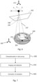
- FIG 1 there is depicted a schematic representation of various components of the present disclosure.
- the mobile platform 10 includes connected thereto a high speed imaging means 20.
- the high speed imaging means may be a high speed imaging camera or a plurality of cameras sensitive to the visible light spectrum (400 to 700 nanometres in wavelength).
- the high speed imaging means 20 is connected to a processor 30 which is configured to receive inputs from the location sensor 40 and the high speed imaging means 20.
- the mobile platform may also include an illumination means (not shown) for increasing the amount of light provided to the subject in the field of view of the high speed imaging means.
- the processor 30 is in communication with memory storage (not shown), which stores information such as location and feature information as is detailed further below.
- the results from the image processing conducted on images acquired by the high speed imaging means 20 and analysed by the processor 30 based upon information provided by the location sensor 40 may be displayed on a display 50.
- the display 50 may be located on the mobile platform or may alternatively be remote from the system.
- FIG 2a there is depicted an exemplary top view of one type of light in an airfield ground lighting system, in this case without any defects.
- the light 100 depicted in Fig 2a has a plurality of bolts 110 in holes 108 which retain the lights in a position in the runway or concourse (the holes are not shown in Fig 2a but are visible in Fig 2b ).
- the bolts are located in a metal ring 112 which is surrounded by an epoxy ring 114, which allows for some movement in-situ during thermal expansion/contraction of the light relative to the surrounding asphalt (e.g. during environmental temperature variation).
- the actual light is emitted from an inset light 116 at the centre of the metal and epoxy ring arrangement.
- Figs 2a- 2e have variable geometries, arrangements of bolts/nuts and inset lights, and are exemplary only. Alternative or additional items to be checked may also be present in the lights which may be monitored as taught in the present disclosure without departing from the scope of the present invention.
- FIG. 2e there is depicted an exemplary schematic view of the light of Fig 2a having a number of integrity issues. These issues are highlighted by the various exploded boxes for emphasis as is detailed below and exemplary representations of the types of issues which may be detected by the present disclosure.
- Condition of the lights needs to be monitored so that action can be undertaken to prevent and/or remedy failure.
- Fig 2e there is a mixture of conditions representative of a typical state of a light in the airfield ground lighting system.
- the head of the bolt located in the 10 o'clock position 110a is in an appropriate position.
- the second bolt 110b at 12 o'clock position is present and aligned appropriately.
- the third bolt 110c is loosened relative to the position in which it should be, represented by the misalignment of a centreline of the bolt with a corresponding feature.
- a variety of bolts/nuts could be used, with or without marked centrelines and having variables numbers of sides, dimensions etc. without departing from the present disclosure).
- Bolt 110d at 4 o'clock is present, and in a correct position and alignment.
- Bolt 110e located at the 6 o'clock position has been loosened relative to its appropriate position, and bolt 110f at the 7 o'clock position is missing.
- a crack is located in the epoxy ring located at the 5 o'clock position and shown in expanded view 114a.
- FIGs 3a and 3b there is depicted a schematic perspective view of the light 100, showing the image acquisition means 20 at various instances in the time interval t1 to t6; together with various coordinate frames of the light and of the image acquisition means.
- the origin of the camera/image acquisition means 20 is represented as a dot 20 which traverses in the direction of from the left to the right of the page as the movable platform 10 moves across the light 100.
- This movement of the image acquisition means 20 is represented by the dots labelled t1 to t6.
- the field of view 150 of the image acquisition means 20 as it traverses the light 100 at various points t1 to t6 is common in Fig 3a shown
- the coordinate frame (fixed) of the light 100 is represented by coordinate frame 160.
- the various points in the "real world" which make up the items to be checked in the actual light of the light are fixed relative to this coordinate frame.
- the frame of reference for the high speed image acquisition means 20 at the various time intervals is depicted by the successive coordinate frames shown in the figure and marked with numerals 171, 172, 173, 174, 175 and 176.
- Fig 3b the same coordinate frame for the high speed image acquisition means at various points t1, t2, t3, t4, t5 and t6 can be seen - 171, 172, 173, 174, 175 and 176.
- the fixed coordinate frame of reference for the light is depicted by coordinate frame 160.
- the various fields of view 150, 151, 152, 153 and 154 of the image acquisition means correspond to the fields of view for the image acquisition means at various time interval.
- the combination of the various fields of view of the high speed image acquisition means of the various time intervals together provide a composition field of views, in contrast to the single common field of view shown in Fig 3a .
- Fig 4 depicts a schematic representative view of the light 100 and representative image planes showing a small circle representing one of the points that make up the actual item of the light to be monitored (e.g. a particular portion of the light such as a bolt or metal ring).
- the "scene point" of the light is depicted in an image captured by the image acquisition means at three different positions at t1, t2 and t3 respectively.
- each image plane contains a point representative of corresponding scene point 191 of the light 100 represented by small circles ( 191a , 191b, 191c ) on the image planes shown.
- the scene point 191 of the light 100 is depicted in the image plane 181 as point 191a. This point is the point of intersection in the image plane of a normal to the image plane, drawn to extend from the image acquisition means 20 at time interval t1, and to the scene point 191 in actual three dimensional space for the light 100.
- scene point 191 of the light depicted in image plane 182 as 191b is the point of intersection in the image plane of a normal to the image plane, drawn to extend from the image acquisition means 20 at time interval t2, and to the scene point 191 in actual three dimensional space for the light 100.
- Points 191a, 191b, 191c represent images of scene point 191 of the light 100 which are located in various positions in the image captured - ranging from the far left side through the middle and towards the far right side of the image depending on the position of the high speed imaging means relative to the scene point as it traverses the light.
- Figs 5a- 5c there is shown a way for rectifying inaccuracies in detection by increasing the sensitivity and reliability of the extraction technique by considering a series of images of the same subject (a light used in an airfield ground lighting system) when captured from a moving image acquisition means.
- Identification of points making up the items to be checked from a first image followed by determination of the location of such points in the frame of reference for each image thereafter enables projection of a theoretical location of the scene points into one or more subsequent images of the light. It is noted that in itself this does not increase the accuracy of the feature detection in the series of images.
- the presence of points making up an item to be checked in images in an image stream can be verified by processing a first image to detect the location of the point(s), then processing a subsequent image by allowing for the change in the position of the image acquisition means between the two images. Verification may be provided by comparing a projection of where the point(s) should be in the subsequent image is undertaken against extracted points, to determine whether the projection from the corresponding "scene" point(s) are actually in the subsequent image at their predicted location.
- a threshold score value above which point(s) comprising an item are considered as being present within an image, and as between subsequent images means a number of images can be analysed to provide certainty as to the presence/absence of particular point(s) making up the item to be checked. This in turn enables the determination of the whether integrity issues in in the actual real world subject of that image, in this case, in a light of an airfield ground lighting system exist.
- Figs 5a - 5c and Fig 6 represent the detection of a specific scene point 191 in the light 100, but it would be appreciated that other scene point(s) comprising items to be checked could be detected. It would be appreciated that the light depicted in the image being checked could have any one or more of the integrity issues shown in Figs 2a-d without departing from the scope of the present disclosure.
- a light 100 including a variety of defects and with the same components as the system identified in Fig 4 .
- the image acquisition means (represented by the dot 20 ) traverses the light 100, capturing a series of images which are represented by image planes 181, 182, 183.
- a feature corresponding to the metal ring on the light 100, scene point 191 is represented on the image plane as feature point 191a.
- the coordinate frame for the light 100 is depicted as 160, and is fixed for each of Fig 5a , 5b, 5c in three dimensional space for the images in the image stream.
- the coordinate frame for the image acquisition means at t1 is 171 in Fig 5a , which schematically depicts the first image acquisition in the image stream and the position of the respective components at the point of acquisition.
- image plane 182 represents the image acquired of the light 100, from the position of the image acquisition means 20 at t2, having a coordinate frame 172.
- the frame of reference for the light 100 remains constant with coordinate frame 160.
- a point which is part of the metal ring 191 of the light 100 is detected as feature point 191b on plane 182.
- This error is apparent, when the point 191c on the next image plane 183 acquired from the image acquisition means 20 with a frame of reference 173 and the frame of reference for the light 160 is detected, as shown in Fig 5c .
- This point 191c represents the scene point 190 of the metal ring of the light 100 at t3.
- the light 100 has scene points 191 and 195 of a coordinate frame of reference 160.
- the image acquisition means 20 depicted by a dot travels across the light 100 with the positions at time t1, time t2 and time t3 indicated by arrows.
- the actual dot is shown at position t2, with a corresponding frame of reference 172 for the image acquisition means.
- a normal line 197 extends from the image acquisition means orthogonal to that image plane.
- the point 191b is detected in the image at t2 on the image plane 182, corresponding to the scene point 191 in the actual light.
- Fig 6 also shows the detection of an error point indicated by 192, which represents in incorrectly identified point, in this instance corresponding to scene point 195.
- the points which comprise various items in the image to be checked are specified (for example, the points making up the conditions of missing bolt/nut, loosened bolt/nut, missing light, missing ring and crack in an epoxy etc.)
- the imaging process 250 can be conducted.
- the imaging process 250 requires propelling (either attached to a vehicle or manually pushing) the moveable platform of the present disclosure across the lights in order to acquire images.
- Airfields may be divided into separate zones with different checking required of the lights in the respective zones depending on the level of usage and surface conditions.
- Lights in respective zones may be associated with a unique identifier, which enables logging the state of the items of a specific light to be checked based upon a specific image stream. This means that an operational baseline for each light can be established - determining when maintenance is required, and once performed, whether the maintenance team has actually addressed a particular integrity issue.
- a fastener such as a bolt may be detected as loosened after capturing a first image stream, when the platform is moved across the airfield. This integrity issues may be passed on to maintenance for rectification. When the platform is moved across the airfield again, the aforementioned bolt of that light may be verified as being tightened in the next captured image stream of this light.
- corrections and analysis techniques 260 can be employed to ensure that the appropriate points are detected, reducing false positive and false negative detection errors.
- Error sources include variation in the position of the image acquisition means (e.g. due to bumping), tyre residue on the light confusing feature detection, variability in illumination conditions, angles, calibration errors, variance in surface condition, artefacts from painting, wet surfaces etc.
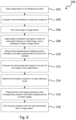
- FIG 8 there is an exemplary flow chart which sets out in more detail the characterisation process 200 conducted to calibrate the inspection system for lights.
- This flow chart depicts a training method by which the points that characterise the item to be checked and hence the operational status of a light can be recognised by the system. This enables the system to identify points in an image, and then discriminate between correctly detected points and incorrectly detected points in an image stream of a particular light for certainty of detection (errors may arise due to variance in the imaging process as discussed above).
- the images of a light of a particular type are acquired by propelling the platform over the light in situ. Location information is also captured for during the acquisition of the images in the image stream of the particular light.
- Location information may be also include information determined from Global Naviation Satellite Systems such as GPS, GLONASS, Beidou, Galileo or similar such systems without departing from the present disclosure, either together with or in addition to location information on the various lights in the specific airfield.
- Global Naviation Satellite Systems such as GPS, GLONASS, Beidou, Galileo or similar such systems without departing from the present disclosure, either together with or in addition to location information on the various lights in the specific airfield.
- Movement may be accurately determined by inertial measurement, using a dead reckoning method such as MEMS type tri-axial inertial sensor (such as an accelerometer (with or without rate gyro)).
- the dead reckoning method utilized can be achieved by modelling updated measurement and sensor error in an optimal state estimator such as a Kalman filter.
- an optimal state estimator such as a Kalman filter.
- inertial measurement such as linear acceleration may be used to deduce the distance travelled, and measurement error can be modelled by first principles, and verified by subsequent data sampling).
- the movement of the image acquisition means when capturing the images in the image stream can be determined.
- step 206 the operator selects an initial image from the image stream of the light being characterised.
- this "initial image” does not necessarily need to be the very first image in the image stream, it is merely an image which precedes the subsequently selected image in the image stream).
- the location, orientation and region of the items to be checked for subsequent automated detection can be manually labelled by the operator on this image, using a mouse or cursor to highlight the appropriate region comprising an item of interest - as a "bag/group" of points in step 208.
- a subsequent image of the plurality of images following in the image stream of the light 100 then may also be selected and then manually reviewed.
- the outcome of this manual review is specification of the "bag/group of points" which makes up each item to be checked for a specific type of light for that pair of images.
- step 210 within the specified "bag of points" in a region, there are certain characteristics (e.g. a predetermined spatial relationship, frequency of occurrence, shading etc.) which amount to a characteristic signature for the feature to be checked in that specific light.
- certain characteristics e.g. a predetermined spatial relationship, frequency of occurrence, shading etc.
- Various parameters such as the histogram of oriented gradients and normalised gradients can also be determined for the specified "bag of points" in the item to further assist.
- the camera orientation may be determined using location information, which is based upon the movement information determined for the consecutive positions of the image acquisition means in step 204 and the location of the point pairs in a particular orientation in the subsequent consecutive images.
- a direct linear transform could be employed to carry out the prediction of the position of the camera during the acquisition of the other images in the image stream where there are less than four or more point pairs. (It would be appreciated that once there are more pairs, optimisation techniques can be utilised, such as the least square method etc.).
- the corresponding location of the points comprising the item to be checked in the actual light depicted in these images can be identified in step 214. This can be done by using epipolar geometry using the known location of the image acquisition means for the initial image and subsequent image of the image stream.
- the location of each of the points can then be projected to all of the images in the image stream as shown in step 216.
- the anticipated locations of the points in subsequent images in an image stream of a light can be predicted.
- This process can then be repeated for all points making up an item to be checked in the subject light, and then for all items in the subject light, to characterise various states and conditions of the points therein.
- a supervised learning approach such as a discriminative classifier can be used to process the images to confirm the point extraction process for the image in the image stream of the specific light as is represented by step 218.
- such a discriminative classifier may involve using a labelled sample which allow for points to be described in higher dimensional space, and projected to other dimensional spaces thus enabling comparison of points with respect to each other or against a baseline, by drawing a simple line. In this way, the points are linearly separable.
- the projection of the anticipated location of points comprising an item in subsequent images reduces significantly the amount of tedious manual labelling required.
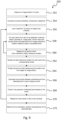
- FIG. 9 there is depicted an exemplary flow chart in which the steps of imaging and detection 250 and correction and analysis 260 of Fig 7 are actually performed.
- an image stream of a light is captured by moving the housing across the light 100. Location information is also captured as has previously been detailed at step 204. It would be appreciated that this image stream would be one of many image streams of many lights acquired as the housing is moved across the airfield. However, for the purposes of simplification, the process is described with respect to one such image stream of one light.
- Captured location information is then used to determine the location of the image acquisition means between consecutive capture points in step 254.
- step 256 the "signature" of points comprising each item in the light to be checked is loaded. (As previously described in relation to step 210, items of the light to be checked have unique characteristics which have been identified following the training 200 depicted in Fig 8 , and it is this record which is loaded.)
- a pair of images is processed to determine a probable location in the light coordinate frame of that feature.
- a corresponding location of the point in the actual real world light coordinate frame is determined as taught by step 214.
- step 262 This process is then repeated in step 262 for all the desired points to be checked, in all items to be checked, for multiple randomly selected pairs, in order to determine multiple locations of the various "real world" points with respect to the light coordinate frame for each of the points which make up the various items to be checked.
- the best scene point or reference location for each of the points in the item to be checked is determined. This may entail using k means clustering or similar such processes.
- the best reference location for a point is stored.
- the determined position for the image acquisition means of that image in the image stream, the stored reference location, and the movement of the image acquisition means are all used to project from the appropriate reference location for that point and the viewpoint of the image acquisition means into where corresponding locations for that point would appear in subsequent images in the image stream in step 264.
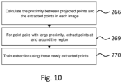
- the images in the image stream can then be processed in 266, by image processing to detect proximity.
- the integrity of the point extraction can then be determined by calculating how close the projected points and detected points are in the images, allowing for the change in position of the relevant viewpoint of the image acquisition means. This may entail using both intrinsic and extrinsic camera parameters.
- step 266 the projected location of a scene point and the detected location of that scene point in each image in the image stream are compared. (This process is undertaken for all points which make up a single item to be checked in the images of the image stream).
- the comparison made at step 266 is between the estimated or anticipated position of a point (based upon location information and the determined image acquisition location) as compared to location of the point detected from an image (according to the specified characteristics used for image detection of that point).
- the proximity can be reflected as a score, which is representative of a pixel distance by theoretical and detected features for that image.
- a score that is inversely proportional to the sum of this distance across the images can be used as a score determining the presence of an item in an image. Therefore, when distances between the detected location and the projected location are large, this point in that image has a low score.
- the above processing steps then can be repeated for all of the points which make up the item in the light to be checked at step 270. Similarly, this process may be repeated for the points which make up other items which are being checked.
- the state of the item being checked can be determined by conducting further analysis at step 270.
- the orientation position and presence of the item may be evaluated.
- the presence of a combination of corners, surface line contours and various "chromatic image patches" for the typical of a head of a bolt/nut as well as the absence of circular contours and chromatic patterns can be used to determine the presence of a bolt/nut at particular locations of the light.
- the presence and location of corners and the orientation of the corners and lines of a bolt/nut can also be used to determine the orientation of the bolt. This means that based upon the characterisation survey at step 200 in Fig 7 and the detected image acquisition orientation when capturing the actual image stream that has been determined in process 250, the relative position of the bolt head/nut may be determined. That is, whether a bolt is loosened or missing may be identified using the corrected detection of that points comprising the item as discussed above.
- the presence of the inset light may be detected by the presence and absence of certain combinations of chromatic image patches contours and corners.
- the detection of an epoxy ring 114 can be made by the detection of patches and circular lines.
- the presence of certain characteristic lines or contours corners in combination with chromatic image patches in the region of the epoxy ring can be used in the determination of whether a crack is present.
- step 266 the proximity between the projected point making up the item to be checked and the feature in image as detected is determined.
- step 268 where a large separation exists between the projected point and the detected point of each image, this means that the detected point can be considered as not being representative of the actual point of the item. However, this can also be a useful training aid for other features including histogram of oriented gradients and normalized gradients which could be used to detect this point.
- this feedback may be incorporated in the characterisation process discussed in Fig 8 .
- Various points around the extracted point with the large discrepancy/difference can be used for example as a labelled sample for training to recognise this point in future extractions.
- the process and system of the present disclosure is able to reinforce the accuracy of the detection and processing to cater for additional items to be checked which may not have been specified in the initial characterisation process.
- the present disclosure provides a method and system which avoids the tedious manual process of airfield ground lighting system inspection.
- the present disclosure ensures a highly accurate and potentially continuously improving system. Once lights of a particular model have been characterised, the system is configured such that variants in acquisition of the image and lighting conditions do not have a significant impact on the detection accuracy.
- the present disclosure provides a time saving, accurate, and cost effective way of managing the ongoing inspection of lights.
- the inspection system of the present disclosure reduces runway closure times, enables inspection in even bad weather, and enables complete lifecycle management of an airfield's significant fixed infrastructure investment in airfield ground lighting.
- the prompt maintenance and rectification of issues enabled by the inspection system of the present disclosure also reduces the potential for foreign object debris on the runway areas from the airfield ground lighting system.
Landscapes
- Engineering & Computer Science (AREA)
- Physics & Mathematics (AREA)
- Theoretical Computer Science (AREA)
- General Physics & Mathematics (AREA)
- Multimedia (AREA)
- Computer Vision & Pattern Recognition (AREA)
- Health & Medical Sciences (AREA)
- General Health & Medical Sciences (AREA)
- Databases & Information Systems (AREA)
- Signal Processing (AREA)
- Quality & Reliability (AREA)
- General Engineering & Computer Science (AREA)
- Human Computer Interaction (AREA)
- Artificial Intelligence (AREA)
- Psychiatry (AREA)
- Social Psychology (AREA)
- Medical Informatics (AREA)
- Evolutionary Computation (AREA)
- Computing Systems (AREA)
- Software Systems (AREA)
- Life Sciences & Earth Sciences (AREA)
- Aviation & Aerospace Engineering (AREA)
- Mechanical Engineering (AREA)
- Acoustics & Sound (AREA)
- Chemical & Material Sciences (AREA)
- Analytical Chemistry (AREA)
- Biochemistry (AREA)
- Immunology (AREA)
- Pathology (AREA)
- Image Analysis (AREA)
- Length Measuring Devices By Optical Means (AREA)
- Image Processing (AREA)
- Non-Portable Lighting Devices Or Systems Thereof (AREA)
Description
- The present disclosure relates to an improved method, system and apparatus for automated inspection of airfield ground lighting.
- Airfields are equipped with specialized lighting systems to provide guidance to planes taking off, landing and taxiing. The guidance system provided by airfield ground lighting (inset and elevated lights) is a particularly important visual aid in conditions of poor visibility arising from weather conditions or for low light conditions.
- Airfield ground lighting is exposed to a harsh environment, with repeated contact with aircraft tires, ground vehicle tires and variable weather conditions, which can diminish the reliability and effectiveness of operation.
- International Civil Aviation Organisation (ICAO) standards specify the importance of regular integrity checking of the airfield ground lighting in view of the frequent and significant impact with aircraft tires.
- Photometric inspections of the airfield ground lighting may be conducted for example by using a mobile apparatus which is towed across the runway by a vehicle, monitor the actual light beams emitted from the lights. However, in addition to the photometric inspection, it is also necessary to conduct regular checks of the lights to monitor such as missing or loosened bolts, or other components or cracks in the actual lights of the airfield ground lighting system.
- Typically these checks are performed by closing the runway and manually viewing each and every light, either by having trained maintenance workers move along the lights by walking or with the assistance of a slow moving or frequently stopping vehicle. As can be appreciated, this manual inspection is laborious, time consuming and inefficient although at the same time critically important for ensuring the integrity and reliability of the lights.
- However, with the increased aircraft passenger travel creating an increased number and frequency of flights and hence pressure on existing airfields, runway closures impact on the efficiency and profitability of airfield operation.
- Accordingly the system and method of the present disclosure provide an alternative which addresses at least some of the above deficiencies.
- A relevant prior art is: PENG J-X ET AL: "Fast model-based feature matching technique applied to airport lighting", IET SCIENCE, MEASUREMENT AND TECHNOLOGY, vol. 2, no. 3, 1 May 2008 (2008-05-01), pages 160-176, XP006030744,ISSN: 1751-8830, DOI: 10.1049/IET-SMT:20070034.
- This prior art discloses a system for monitoring an approach lighting system of an airport, with the aim of highlighting and repairing any under-performing luminaires, using a vision system embedded in an aircraft and the position of the aircraft, where a set of blobs is extracted from the image associated with the coordinates of a luminaire, and the reference location for each extracted point is determined. The 3D coordinates of the luminaires are projected from the airport coordinate system to the camera coordinate system and correspondence between blobs and template luminaires are calculated using a distance threshold applied such that only those correspondence pairs with a distance not greater than the threshold are selected.
- The invention is defined by an airfield ground lighting inspection system as recited in the appended claims.
- Preferred embodiments of the present disclosure will be explained in further detail below by way of examples and with reference to the accompanying drawings, in which:-
-
Fig 1 shows a schematic view of an exemplary arrangement of an embodiment of the airfield ground lighting system of the disclosure; -
Fig 2a shows an exemplary schematic view of a light of the airfield ground lighting system without defects; -
Fig 2b shows an exemplary computer rendered representation of another type of light used in airfield ground lighting systems without defects; -
Fig 2c shows an exemplary photograph of another type of light used in airfield ground lighting systems without defects (clean); -
Fig 2d shows an exemplary photograph of the light ofFig 2c without defects (after use); -
Fig 2e shows a schematic view of the light ofFig 2a having a number of defects; -
Fig 3a shows a schematic perspective view of the light and optical centres of the image acquisition means of the moveable platform as it traverses across an exemplary light; -
Fig 3b shows a schematic perspective view of the light and optical centres of the image acquisition means of the moveable platform as it traverses across a light where the images in the image stream have different and overlapping fields of view; -
Fig 4 shows a schematic perspective view of the light and representative images captured from the image acquisition means of the moveable platform; -
Fig 5a shows a schematic perspective view of the light and a representative image captured by the image acquisition means of the moveable platform in an initial position at t= t1; -
Fig 5b shows a schematic perspective view of the light and representative image thereof captured by the image acquisition means of the moveable platform in an subsequent position at time t= t2; -
Fig 5c shows a schematic perspective view of the light and representative image thereof captured by the image acquisition means of the moveable platform in at a final position at time t= t3; -
Fig 6 shows a schematic perspective view of the light and representative image thereof, including an incorrectly detected feature; -
Fig 7 depicts an exemplary flow chart according to an embodiment of the present disclosure outlining the various stages in deployment of the system; -
Fig 8 depicts an exemplary training flow chart of the training phase of an embodiment of the present disclosure; -
Fig 9 depicts an exemplary flow chart outlining the various steps in an image detection method according to an embodiment of the present disclosure; -
Fig 10 depicts an exemplary "learning" algorithm by which the feature extraction sensitivity may be improved. - In a broad aspect of the present disclosure, there is provided an improved airfield lighting inspection system, which provides reliable, automated checking using image analysis of the lights in airfield ground lighting system.
- Referring to
Fig 1 , there is depicted a schematic representation of various components of the present disclosure. - The
mobile platform 10 includes connected thereto a high speed imaging means 20. The high speed imaging means may be a high speed imaging camera or a plurality of cameras sensitive to the visible light spectrum (400 to 700 nanometres in wavelength). The high speed imaging means 20 is connected to aprocessor 30 which is configured to receive inputs from thelocation sensor 40 and the high speed imaging means 20. - The mobile platform may also include an illumination means (not shown) for increasing the amount of light provided to the subject in the field of view of the high speed imaging means.
- Advantageously, the
processor 30 is in communication with memory storage (not shown), which stores information such as location and feature information as is detailed further below. - The results from the image processing conducted on images acquired by the high speed imaging means 20 and analysed by the
processor 30 based upon information provided by thelocation sensor 40 may be displayed on a display 50. Advantageously, the display 50 may be located on the mobile platform or may alternatively be remote from the system. - It would be appreciated that the actual processing of images may occur at a geographically remote location from the mobile vehicle, provided that the images and accompanying location information are indexed appropriately, without departing from the scope of the present invention.
- Turning now to
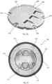
Fig 2a , there is depicted an exemplary top view of one type of light in an airfield ground lighting system, in this case without any defects. - The
light 100 depicted inFig 2a has a plurality ofbolts 110 inholes 108 which retain the lights in a position in the runway or concourse (the holes are not shown inFig 2a but are visible inFig 2b ). The bolts are located in ametal ring 112 which is surrounded by anepoxy ring 114, which allows for some movement in-situ during thermal expansion/contraction of the light relative to the surrounding asphalt (e.g. during environmental temperature variation). The actual light is emitted from aninset light 116 at the centre of the metal and epoxy ring arrangement. - Many of these items can also be seen in the computer rendered representation of the light depicted in
Fig 2b and in the photograph of an actual light ofFig 2c (clean) and the light (after use) shown inFig 2d . (The embodiment ofFig 2b does not include an inset light which is separable from themetal ring 112, and theepoxy ring 114 has been removed for clarity). - It would also be appreciated that the lights depicted in
Figs 2a- 2e have variable geometries, arrangements of bolts/nuts and inset lights, and are exemplary only. Alternative or additional items to be checked may also be present in the lights which may be monitored as taught in the present disclosure without departing from the scope of the present invention. - Referring now to
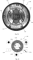
Fig 2e , there is depicted an exemplary schematic view of the light ofFig 2a having a number of integrity issues. These issues are highlighted by the various exploded boxes for emphasis as is detailed below and exemplary representations of the types of issues which may be detected by the present disclosure. - Typically, lights in an airfield ground lighting system receive a significant loading force when contacted by the landing gear of aircraft as they touch down. Rubber residue from melted tyres, loosened and missing bolts/nuts, cracked epoxy, misalignment of bolts and other integrity issues can be caused by this repeated cyclical wear.
- Condition of the lights needs to be monitored so that action can be undertaken to prevent and/or remedy failure.
- Turning to
Fig 2e , there is a mixture of conditions representative of a typical state of a light in the airfield ground lighting system. For example, as depicted the head of the bolt located in the 10 o'clock position 110a is in an appropriate position. Thesecond bolt 110b at 12 o'clock position is present and aligned appropriately. However, thethird bolt 110c is loosened relative to the position in which it should be, represented by the misalignment of a centreline of the bolt with a corresponding feature. (It would be appreciated that a variety of bolts/nuts could be used, with or without marked centrelines and having variables numbers of sides, dimensions etc. without departing from the present disclosure). -
Bolt 110d at 4 o'clock is present, and in a correct position and alignment. -
Bolt 110e located at the 6 o'clock position has been loosened relative to its appropriate position, and bolt 110f at the 7 o'clock position is missing. - A crack is located in the epoxy ring located at the 5 o'clock position and shown in expanded view 114a.
- Appropriate maintenance action needs to be taken before the performance of the light depicted in
Fig 2e is compromised. - It would be appreciated that the specific integrity issues of
Fig 2e are exemplary only, as is the layout and configuration depicted. A variety of other integrity issues which are visually apparent may also be detected and the present disclosure is not limited to the integrity issues detailed inFig 2e . Additionally, a variety of fasteners, and nut and bolt arrangements may be utilized without departing from the scope of the present disclosure. - Referring now to
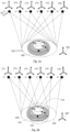
Figs 3a and 3b , there is depicted a schematic perspective view of the light 100, showing the image acquisition means 20 at various instances in the time interval t1 to t6; together with various coordinate frames of the light and of the image acquisition means. - For simplicity, the origin of the camera/image acquisition means 20 is represented as a
dot 20 which traverses in the direction of from the left to the right of the page as themovable platform 10 moves across the light 100. This movement of the image acquisition means 20 is represented by the dots labelled t1 to t6. - The field of
view 150 of the image acquisition means 20 as it traverses the light 100 at various points t1 to t6 is common inFig 3a shown
For ease of reference, the coordinate frame (fixed) of the light 100 is represented by coordinateframe 160. Relative to this coordinate frame, the various points in the "real world" which make up the items to be checked in the actual light of the light are fixed relative to this coordinate frame. - The frame of reference for the high speed image acquisition means 20 at the various time intervals is depicted by the successive coordinate frames shown in the figure and marked with
numerals - Referring to
Fig 3b , the same coordinate frame for the high speed image acquisition means at various points t1, t2, t3, t4, t5 and t6 can be seen - 171, 172, 173, 174, 175 and 176. The fixed coordinate frame of reference for the light is depicted by coordinateframe 160. - In the representation of
Fig 3b , the various fields ofview Fig 3b , the combination of the various fields of view of the high speed image acquisition means of the various time intervals together provide a composition field of views, in contrast to the single common field of view shown inFig 3a . -
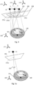
Fig 4 depicts a schematic representative view of the light 100 and representative image planes showing a small circle representing one of the points that make up the actual item of the light to be monitored (e.g. a particular portion of the light such as a bolt or metal ring). Thus the "scene point" of the light is depicted in an image captured by the image acquisition means at three different positions at t1, t2 and t3 respectively. - Specifically, the 2-dimensional images captured are represented by
image planes corresponding scene point 191 of the light 100 represented by small circles (191a, 191b, 191c) on the image planes shown. - It would be appreciated that the
scene point 191 of the light 100 is depicted in theimage plane 181 aspoint 191a. This point is the point of intersection in the image plane of a normal to the image plane, drawn to extend from the image acquisition means 20 at time interval t1, and to thescene point 191 in actual three dimensional space for the light 100. - Similarly,
scene point 191 of the light depicted inimage plane 182 as 191b. This point is the point of intersection in the image plane of a normal to the image plane, drawn to extend from the image acquisition means 20 at time interval t2, and to thescene point 191 in actual three dimensional space for the light 100. - Accordingly, as the high speed image acquisition means traverses across the light, the subsequent images captured are represented by
image planes Points scene point 191 of the light 100 which are located in various positions in the image captured - ranging from the far left side through the middle and towards the far right side of the image depending on the position of the high speed imaging means relative to the scene point as it traverses the light. - These series of images forming an image stream of a light could be analysed one-by-one to determine the presence or absence of points in the images, (and thereafter to determine the presence or absence of the group of points which make up particular items in the image to be checked). As is known in the art, detection of points in an image utilises known extraction algorithms, or may be conducted by manual processing.
- However, variations in the optical characteristics of the light (including marking with rubber residue, loosened or damaged parts etc.) as well as variables in the position of the image acquisition means (including bumpiness of the moveable vehicle altering field of view of image acquisition device etc.), can mean that the series of images in the image stream may include points which are extracted and identified incorrectly. Hence, no single image of the image stream can be relied upon to definitively determine the location of that point in the actual light coordinate frame.
- When taken together, incorrect extraction of points in the images means that false detections of the items to be checked may occur. Thus, capturing a series of images and attempting to interpret these using the above approach provides inconsistent and inaccurate results-without reliability for example on the alignment, presence or absence of a crack in the epoxying, and presence or absence of the bolts/nuts to be checked.
- Referring to the schematic representation of the system depicted by
Figs 5a- 5c , there is shown a way for rectifying inaccuracies in detection by increasing the sensitivity and reliability of the extraction technique by considering a series of images of the same subject (a light used in an airfield ground lighting system) when captured from a moving image acquisition means. - Identification of points making up the items to be checked from a first image followed by determination of the location of such points in the frame of reference for each image thereafter (i.e. allowing for the relative displacement of the image acquisition means) enables projection of a theoretical location of the scene points into one or more subsequent images of the light. It is noted that in itself this does not increase the accuracy of the feature detection in the series of images.
- However, the presence of points making up an item to be checked in images in an image stream can be verified by processing a first image to detect the location of the point(s), then processing a subsequent image by allowing for the change in the position of the image acquisition means between the two images. Verification may be provided by comparing a projection of where the point(s) should be in the subsequent image is undertaken against extracted points, to determine whether the projection from the corresponding "scene" point(s) are actually in the subsequent image at their predicted location.
- By specifying a threshold score value above which point(s) comprising an item are considered as being present within an image, and as between subsequent images, means a number of images can be analysed to provide certainty as to the presence/absence of particular point(s) making up the item to be checked. This in turn enables the determination of the whether integrity issues in in the actual real world subject of that image, in this case, in a light of an airfield ground lighting system exist.
-
Figs 5a - 5c andFig 6 represent the detection of aspecific scene point 191 in the light 100, but it would be appreciated that other scene point(s) comprising items to be checked could be detected. It would be appreciated that the light depicted in the image being checked could have any one or more of the integrity issues shown inFigs 2a-d without departing from the scope of the present disclosure. - Turning to
Figs 5a- 5c , there is shown a light 100 including a variety of defects and with the same components as the system identified inFig 4 . The image acquisition means (represented by the dot 20) traverses the light 100, capturing a series of images which are represented byimage planes - Similar to the system depicted in
Fig 4 , in the system ofFigs 5a-c , a feature corresponding to the metal ring on the light 100,scene point 191, is represented on the image plane asfeature point 191a. - The coordinate frame for the light 100 is depicted as 160, and is fixed for each of
Fig 5a ,5b, 5c in three dimensional space for the images in the image stream. - The coordinate frame for the image acquisition means at t1 is 171 in
Fig 5a , which schematically depicts the first image acquisition in the image stream and the position of the respective components at the point of acquisition. - As the image acquisition means traverses across the light, the field of view and positions of various components changes to the arrangement depicted by
Fig 5b . - In
Fig 5b ,image plane 182 represents the image acquired of the light 100, from the position of the image acquisition means 20 at t2, having a coordinateframe 172. The frame of reference for the light 100 remains constant with coordinateframe 160. - As depicted, a point which is part of the
metal ring 191 of the light 100 is detected asfeature point 191b onplane 182. - However, another
point 192 is also detected, which is actually another feature of the metal ring of the light 100 as depicted byscene point 195. - This error is apparent, when the
point 191c on thenext image plane 183 acquired from the image acquisition means 20 with a frame ofreference 173 and the frame of reference for the light 160 is detected, as shown inFig 5c . Thispoint 191c represents thescene point 190 of the metal ring of the light 100 at t3. - Accordingly, based upon movement from
Fig 5a to Fig 5b of the image acquisition means and the movement fromFig 5b to Fig 5c of the same image acquisition means, incorrect detection of thescene point 192 on the light 100 in processingFig 5b can be ignored, based upon reliable detection of the points depicted by 191 a,b,c onimage planes 181, 182,183 shown inFigs 5a- 5c respectively. - More detail on the interpretation and extraction of the points of the items being checked from the images, as well as the determination that an
item 192 has been incorrectly detected is provided below. - Referring now to
Fig 6 , there is shown a schematic depiction of the light 100. The light 100 has scene points 191 and 195 of a coordinate frame ofreference 160. - The image acquisition means 20 depicted by a dot, travels across the light 100 with the positions at time t1, time t2 and time t3 indicated by arrows. In
Fig 6 , the actual dot is shown at position t2, with a corresponding frame ofreference 172 for the image acquisition means. - Similarly as with the figures depicted in
Fig 5a to Fig 5c , relative to theimage plane 182 shown, anormal line 197 extends from the image acquisition means orthogonal to that image plane. As shown, it will be appreciated that thepoint 191b is detected in the image at t2 on theimage plane 182, corresponding to thescene point 191 in the actual light. However,Fig 6 also shows the detection of an error point indicated by 192, which represents in incorrectly identified point, in this instance corresponding toscene point 195. - As discussed with reference to
Figs 5a andFig 5c , by reviewing the images captured from the acquisition means at t1 and t3, the incorrectly detectedscene point 195 in the light 100 can be ignored. Rejection of this incorrect detection of a scene point in turn facilitates more accurate detection of the points which make up the items to be checked, and in turn the overall status of the item(s) for that light to be checked. - An overview of this process, from a conceptual perspective is detailed in
Fig 7 . - As set out, following a survey of the light in the airfield ground lighting to be checked 200, the points which comprise various items in the image to be checked are specified (for example, the points making up the conditions of missing bolt/nut, loosened bolt/nut, missing light, missing ring and crack in an epoxy etc.)
- These items are made up of a series of points which need to be detected. It is necessary to calibrate the system in this way so that it can differentiate between fault states and acceptable states for various status of particular lights to be inspected. This calibration is conducted by the feature characterising training process, which is discussed in more detail below with reference to
Fig 8 . - Once the respective characterisation of status for the lights of a particular airfield lighting system has been performed, the
imaging process 250 can be conducted. - Typically, the
imaging process 250 requires propelling (either attached to a vehicle or manually pushing) the moveable platform of the present disclosure across the lights in order to acquire images. - Airfields may be divided into separate zones with different checking required of the lights in the respective zones depending on the level of usage and surface conditions. Lights in respective zones may be associated with a unique identifier, which enables logging the state of the items of a specific light to be checked based upon a specific image stream. This means that an operational baseline for each light can be established - determining when maintenance is required, and once performed, whether the maintenance team has actually addressed a particular integrity issue.
- For example, a fastener such as a bolt may be detected as loosened after capturing a first image stream, when the platform is moved across the airfield. This integrity issues may be passed on to maintenance for rectification. When the platform is moved across the airfield again, the aforementioned bolt of that light may be verified as being tightened in the next captured image stream of this light.
- If maintenance has not been performed on that light, or has been performed incorrectly this will also be identified by the system and escalated.
- Once the images have been acquired and characterised, corrections and
analysis techniques 260 can be employed to ensure that the appropriate points are detected, reducing false positive and false negative detection errors. Error sources include variation in the position of the image acquisition means (e.g. due to bumping), tyre residue on the light confusing feature detection, variability in illumination conditions, angles, calibration errors, variance in surface condition, artefacts from painting, wet surfaces etc. - Referring now to
Fig 8 , there is an exemplary flow chart which sets out in more detail thecharacterisation process 200 conducted to calibrate the inspection system for lights. This flow chart depicts a training method by which the points that characterise the item to be checked and hence the operational status of a light can be recognised by the system. This enables the system to identify points in an image, and then discriminate between correctly detected points and incorrectly detected points in an image stream of a particular light for certainty of detection (errors may arise due to variance in the imaging process as discussed above). - At
step 202, the images of a light of a particular type are acquired by propelling the platform over the light in situ. Location information is also captured for during the acquisition of the images in the image stream of the particular light. - Location information may be also include information determined from Global Naviation Satellite Systems such as GPS, GLONASS, Beidou, Galileo or similar such systems without departing from the present disclosure, either together with or in addition to location information on the various lights in the specific airfield.
- Movement may be accurately determined by inertial measurement, using a dead reckoning method such as MEMS type tri-axial inertial sensor (such as an accelerometer (with or without rate gyro)). The dead reckoning method utilized can be achieved by modelling updated measurement and sensor error in an optimal state estimator such as a Kalman filter. (For example inertial measurement such as linear acceleration may be used to deduce the distance travelled, and measurement error can be modelled by first principles, and verified by subsequent data sampling).
- This process has been schematically depicted in
Figs 5a to 5c andFig 6 . - Using the captured positional or location information in
step 204, the movement of the image acquisition means when capturing the images in the image stream can be determined. - As
step 206, the operator selects an initial image from the image stream of the light being characterised. (It should be noted that this "initial image" does not necessarily need to be the very first image in the image stream, it is merely an image which precedes the subsequently selected image in the image stream). - The location, orientation and region of the items to be checked for subsequent automated detection can be manually labelled by the operator on this image, using a mouse or cursor to highlight the appropriate region comprising an item of interest - as a "bag/group" of points in
step 208. - A subsequent image of the plurality of images following in the image stream of the light 100 then may also be selected and then manually reviewed. The outcome of this manual review is specification of the "bag/group of points" which makes up each item to be checked for a specific type of light for that pair of images.
- In
step 210, within the specified "bag of points" in a region, there are certain characteristics (e.g. a predetermined spatial relationship, frequency of occurrence, shading etc.) which amount to a characteristic signature for the feature to be checked in that specific light. Various parameters such as the histogram of oriented gradients and normalised gradients can also be determined for the specified "bag of points" in the item to further assist. - At
step 212, for the initial image (and subsequent image) the camera orientation may be determined using location information, which is based upon the movement information determined for the consecutive positions of the image acquisition means instep 204 and the location of the point pairs in a particular orientation in the subsequent consecutive images. - A direct linear transform could be employed to carry out the prediction of the position of the camera during the acquisition of the other images in the image stream where there are less than four or more point pairs. (It would be appreciated that once there are more pairs, optimisation techniques can be utilised, such as the least square method etc.).
- Once the position and orientation of the image acquisition means has been determined for the first and subsequent image, the corresponding location of the points comprising the item to be checked in the actual light depicted in these images can be identified in
step 214. This can be done by using epipolar geometry using the known location of the image acquisition means for the initial image and subsequent image of the image stream. - Based upon the determined location of each of the scene points which make up an item in the light ("in the real world") to be checked, using the locations thus determined as reference locations for the respective scene points and taking the known position of the image acquisition means, the location of each of the points can then be projected to all of the images in the image stream as shown in
step 216. - Therefore, based upon the estimated camera location, location information and manually specified characterisation information, in the first and subsequent following image in the image stream, the anticipated locations of the points in subsequent images in an image stream of a light can be predicted.
- This process can then be repeated for all points making up an item to be checked in the subject light, and then for all items in the subject light, to characterise various states and conditions of the points therein.
- In particular, a supervised learning approach such as a discriminative classifier can be used to process the images to confirm the point extraction process for the image in the image stream of the specific light as is represented by
step 218. - As is known in the art, such a discriminative classifier may involve using a labelled sample which allow for points to be described in higher dimensional space, and projected to other dimensional spaces thus enabling comparison of points with respect to each other or against a baseline, by drawing a simple line. In this way, the points are linearly separable.
- Advantageously, although there is an initial step of labelling the points comprising an item to be checked in the first and subsequent images of the light, there is no need to continue tediously labelling all points for all items to be checked in all subsequent images in an image stream in order to enable accurate detection.
- According to the training method of the present disclosure, the projection of the anticipated location of points comprising an item in subsequent images (after they have been manually specified in the first and subsequent image) reduces significantly the amount of tedious manual labelling required.
- Referring now to
Fig 9 , there is depicted an exemplary flow chart in which the steps of imaging anddetection 250 and correction andanalysis 260 ofFig 7 are actually performed. - At
step 252, an image stream of a light is captured by moving the housing across the light 100. Location information is also captured as has previously been detailed atstep 204. It would be appreciated that this image stream would be one of many image streams of many lights acquired as the housing is moved across the airfield. However, for the purposes of simplification, the process is described with respect to one such image stream of one light. - Captured location information is then used to determine the location of the image acquisition means between consecutive capture points in
step 254. - In
step 256, the "signature" of points comprising each item in the light to be checked is loaded. (As previously described in relation to step 210, items of the light to be checked have unique characteristics which have been identified following thetraining 200 depicted inFig 8 , and it is this record which is loaded.) - At
step 258, for each desired point in the image of the item to be checked for integrity, a pair of images is processed to determine a probable location in the light coordinate frame of that feature. - From the pair of images processed, a corresponding location of the point in the actual real world light coordinate frame is determined as taught by
step 214. - This process is then repeated in
step 262 for all the desired points to be checked, in all items to be checked, for multiple randomly selected pairs, in order to determine multiple locations of the various "real world" points with respect to the light coordinate frame for each of the points which make up the various items to be checked. - At
step 262, the best scene point or reference location for each of the points in the item to be checked is determined. This may entail using k means clustering or similar such processes. - Once the best reference location for a point has been determined it is stored. The determined position for the image acquisition means of that image in the image stream, the stored reference location, and the movement of the image acquisition means are all used to project from the appropriate reference location for that point and the viewpoint of the image acquisition means into where corresponding locations for that point would appear in subsequent images in the image stream in
step 264. - Thus, the images in the image stream can then be processed in 266, by image processing to detect proximity.
- The integrity of the point extraction can then be determined by calculating how close the projected points and detected points are in the images, allowing for the change in position of the relevant viewpoint of the image acquisition means. This may entail using both intrinsic and extrinsic camera parameters.
- Thus, in
step 266 the projected location of a scene point and the detected location of that scene point in each image in the image stream are compared. (This process is undertaken for all points which make up a single item to be checked in the images of the image stream). The comparison made atstep 266 is between the estimated or anticipated position of a point (based upon location information and the determined image acquisition location) as compared to location of the point detected from an image (according to the specified characteristics used for image detection of that point). The proximity can be reflected as a score, which is representative of a pixel distance by theoretical and detected features for that image. - For example, a score that is inversely proportional to the sum of this distance across the images can be used as a score determining the presence of an item in an image. Therefore, when distances between the detected location and the projected location are large, this point in that image has a low score.
- A determination can then be made as to whether the presence of the detected point is present at
step 268. - Optionally, the above processing steps then can be repeated for all of the points which make up the item in the light to be checked at
step 270. Similarly, this process may be repeated for the points which make up other items which are being checked. - Once the points making up an item be detected have been scored for a series of images (based upon correlation with the corresponding projected location of the points in those images) the state of the item being checked can be determined by conducting further analysis at
step 270. - For example, the orientation position and presence of the item may be evaluated. For example, the presence of a combination of corners, surface line contours and various "chromatic image patches" for the typical of a head of a bolt/nut as well as the absence of circular contours and chromatic patterns can be used to determine the presence of a bolt/nut at particular locations of the light.
- The presence and location of corners and the orientation of the corners and lines of a bolt/nut can also be used to determine the orientation of the bolt. This means that based upon the characterisation survey at
step 200 inFig 7 and the detected image acquisition orientation when capturing the actual image stream that has been determined inprocess 250, the relative position of the bolt head/nut may be determined. That is, whether a bolt is loosened or missing may be identified using the corrected detection of that points comprising the item as discussed above. - Similarly, the presence of the inset light may be detected by the presence and absence of certain combinations of chromatic image patches contours and corners. Furthermore, the detection of an
epoxy ring 114 can be made by the detection of patches and circular lines. Finally, in order to detect whether or not an epoxy crack exists in a light, the presence of certain characteristic lines or contours corners in combination with chromatic image patches in the region of the epoxy ring can be used in the determination of whether a crack is present. - Referring now to
Fig 10 , there is discussed in more detail the various steps in the calculation which may be performed atstep 266 and subsequent steps. - At
step 266, the proximity between the projected point making up the item to be checked and the feature in image as detected is determined. - Turning to step 268, where a large separation exists between the projected point and the detected point of each image, this means that the detected point can be considered as not being representative of the actual point of the item. However, this can also be a useful training aid for other features including histogram of oriented gradients and normalized gradients which could be used to detect this point.
- In this way, where there is a large difference between the location comparing the projected feature point (derived by projecting from the scene point to various images in the image stream) and extracted point (extracted based upon image processing technique e.g. histogram of gradient), this feedback may be incorporated in the characterisation process discussed in
Fig 8 . Various points around the extracted point with the large discrepancy/difference can be used for example as a labelled sample for training to recognise this point in future extractions. - Accordingly, the process and system of the present disclosure is able to reinforce the accuracy of the detection and processing to cater for additional items to be checked which may not have been specified in the initial characterisation process.
- The present disclosure provides a method and system which avoids the tedious manual process of airfield ground lighting system inspection.
- By employing a location sensor, image extraction for points making up the various items of the light to be checked, training on an image, and re-projection of the detected items based upon the determined location of the image acquisition means and reference points making up the actual item, the present disclosure ensures a highly accurate and potentially continuously improving system. Once lights of a particular model have been characterised, the system is configured such that variants in acquisition of the image and lighting conditions do not have a significant impact on the detection accuracy.
- Being able to automatically rapidly evaluate the condition of a light enables detailed light cycle monitoring for each light in the airfield. The inclusion of a unique identifier for each light (and the logging of the position information or region) for that light enables a detailed maintenance programme to be provided, with areas of high traffic receiving more attention than corresponding areas.
- Accordingly, the present disclosure provides a time saving, accurate, and cost effective way of managing the ongoing inspection of lights. The inspection system of the present disclosure reduces runway closure times, enables inspection in even bad weather, and enables complete lifecycle management of an airfield's significant fixed infrastructure investment in airfield ground lighting. The prompt maintenance and rectification of issues enabled by the inspection system of the present disclosure also reduces the potential for foreign object debris on the runway areas from the airfield ground lighting system.
- While the present invention has been explained by reference to the examples or preferred embodiments described above, it will be appreciated that those are examples to assist understanding of the present invention and are not meant to be restrictive.
Claims (4)
- An airfield ground lighting inspection system comprising:a housing having an image acquisition means attached thereto configured for capturing a plurality of image streams of a plurality of lights comprising an in ground airfield ground lighting system upon movement of the housing across the airfield;a location sensor for detecting location information for the image acquisition means capturing the plurality of images comprising the image streams;an image processor coupled to the image acquisition and the location sensor for processing the image stream of a light of the airfield ground lighting system by:(a) loading an association of characteristics of a plurality of points in an image with an item to be checked in the image of the light to be checked, and using this association to extract points from the images of the image stream;(b) determining, for a plurality of randomly selected pairs of sample images from the images of the image stream, a plurality of tentative reference locations, one for each of the pairs of images for each extracted point relative to a three dimensional coordinate frame of the light using the location information of the image acquisition means for that pair of images and the detected location of that point in the pair of images;(c) assessing the tentative reference locations determined for each extracted point, to determine a reference location for each extracted point in the three dimensional coordinate frame of the light;(d) projecting each extracted point into the images of the image stream based upon the determined reference location of each extracted point and location information of the image acquisition means for each image;(e) comparing the locations in the images of the extracted points and the corresponding projected points and calculating the proximity therebetween;(f) verifying existence in the image of the point of the item being checked by comparing the calculated proximity against a threshold value;(g) repeating steps (a) to (f) to verify existence of each point in the plurality of points associated with each item to be checked in the light being checked; and(h) determining the state of the item to be checked in the light being checked based upon analysis of verified points.
- The airfield ground lighting inspection system according to claim 1 wherein the system is configured to verify any one or more of the presence of a crack, the absence of any one or more of a bolt, a nut, a ring, and an inset light, and the orientation of any one or more of a bolt, a nut, a ring, an inset light and a crack.
- The airfield ground lighting inspection system according to any one of the preceding claims wherein the plurality of images are acquired under ambient lighting conditions.
- The airfield ground lighting inspection system according to any of claims 1 to 3, wherein an additional illumination means is attached to the movable housing for lighting the lights for image acquisition.
Applications Claiming Priority (2)
| Application Number | Priority Date | Filing Date | Title |
|---|---|---|---|
| HK16114414.1A HK1228649A2 (en) | 2016-12-19 | Automated airfield ground lighting inspection system | |
| PCT/IB2017/057474 WO2018116032A1 (en) | 2016-12-19 | 2017-11-29 | Automated airfield ground lighting inspection system |
Publications (3)
| Publication Number | Publication Date |
|---|---|
| EP3554838A1 EP3554838A1 (en) | 2019-10-23 |
| EP3554838A4 EP3554838A4 (en) | 2020-10-28 |
| EP3554838B1 true EP3554838B1 (en) | 2024-08-07 |
Family
ID=62626008
Family Applications (1)
| Application Number | Title | Priority Date | Filing Date |
|---|---|---|---|
| EP17882651.7A Active EP3554838B1 (en) | 2016-12-19 | 2017-11-29 | Automated airfield ground lighting inspection system |
Country Status (8)
| Country | Link |
|---|---|
| US (1) | US10891727B2 (en) |
| EP (1) | EP3554838B1 (en) |
| KR (1) | KR102281526B1 (en) |
| CN (1) | CN109195799B (en) |
| AU (1) | AU2017381620B2 (en) |
| CA (1) | CA3023398C (en) |
| SG (1) | SG11201807004SA (en) |
| WO (1) | WO2018116032A1 (en) |
Families Citing this family (4)
| Publication number | Priority date | Publication date | Assignee | Title |
|---|---|---|---|---|
| JP6877233B2 (en) * | 2017-05-18 | 2021-05-26 | 清水建設株式会社 | Bolt position detection method and system |
| CN109029382B (en) * | 2018-08-20 | 2023-08-08 | 上海矩尺土木科技有限公司 | Bolt looseness-prevention early warning monitoring device |
| CA3180630A1 (en) | 2020-05-29 | 2021-12-02 | Alexander Harvey | Methods and systems for construct identification and analysis |
| CN112232222B (en) * | 2020-10-19 | 2021-05-07 | 哈尔滨市科佳通用机电股份有限公司 | Bullet train axle box end cover bolt loss fault detection method based on image processing |
Family Cites Families (25)
| Publication number | Priority date | Publication date | Assignee | Title |
|---|---|---|---|---|
| US5485151A (en) * | 1993-05-06 | 1996-01-16 | Adb-Alnaco, Inc. | Airfield lighting system |
| JPH07329895A (en) * | 1994-06-06 | 1995-12-19 | Toshiba Corp | Lamp maintenance device |
| US6996254B2 (en) * | 2001-06-18 | 2006-02-07 | Microsoft Corporation | Incremental motion estimation through local bundle adjustment |
| EP1366989B8 (en) * | 2002-05-27 | 2013-09-25 | DeWiTec GmbH | Method and device for testing illumination means and light signals |
| JP4230395B2 (en) | 2004-03-24 | 2009-02-25 | 三菱電機株式会社 | Surveillance mobile |
| CN1606349A (en) * | 2004-11-30 | 2005-04-13 | 杭州恒生电子股份有限公司 | Method and system for positioning synchronous video monitoring image of service process |
| GB0515157D0 (en) * | 2005-07-23 | 2005-08-31 | Univ Belfast | Light measurement method and apparatus |
| FR2979989B1 (en) * | 2011-09-13 | 2016-01-08 | Fb Technology | MOBILE CONTROL EQUIPMENT FOR AIRBAG BEAMS |
| CN102590882B (en) * | 2011-09-30 | 2013-10-23 | 长春奥普光电技术股份有限公司 | Foreign object monitoring system on airport pavement |
| AU2011265430B2 (en) * | 2011-12-21 | 2015-03-19 | Canon Kabushiki Kaisha | 3D reconstruction of partially unobserved trajectory |
| CN102821524A (en) * | 2012-08-17 | 2012-12-12 | 中国民航大学 | Airfield light single lamp monitoring system based on wireless sensor network |
| US20140055614A1 (en) * | 2012-08-21 | 2014-02-27 | David J. Kahan | Vehicular Pedestrian Sensor Apparatus |
| CN203072198U (en) * | 2012-12-06 | 2013-07-17 | 上海中加飞机机载设备维修股份有限公司 | Airport illumination system |
| CN103116140A (en) * | 2013-02-07 | 2013-05-22 | 沈阳理工大学 | Method for detecting LED visual aid-to-navigation lamps of multi-channel airport |
| CN104915965A (en) * | 2014-03-14 | 2015-09-16 | 华为技术有限公司 | Camera tracking method and device |
| WO2015155628A1 (en) * | 2014-04-07 | 2015-10-15 | Eyeways Systems Ltd. | Apparatus and method for image-based positioning, orientation and situational awareness |
| CA2945540C (en) * | 2014-04-10 | 2021-11-16 | Cooper Technologies Company | Wireless configuration and diagnostics of airfield lighting fixtures |
| WO2016017883A1 (en) * | 2014-07-29 | 2016-02-04 | 한국공항공사 | Active airfield lighting apparatus and active airfield lighting method |
| US9530058B2 (en) * | 2014-12-11 | 2016-12-27 | Toyota Motor Engineering & Manufacturing North America, Inc. | Visual-assist robots |
| US9561865B2 (en) * | 2015-02-16 | 2017-02-07 | Honeywell International Inc. | Systems and methods for improving positional awareness within an airport moving map |
| US20160292518A1 (en) | 2015-03-30 | 2016-10-06 | D-Vision C.V.S Ltd | Method and apparatus for monitoring changes in road surface condition |
| JP6594039B2 (en) * | 2015-05-20 | 2019-10-23 | 株式会社東芝 | Image processing apparatus, method, and program |
| CN105578675B (en) * | 2015-07-02 | 2018-06-26 | 送飞实业集团有限公司 | Internet airfield aid light is shown and control system |
| CN205003546U (en) * | 2015-09-18 | 2016-01-27 | 天津鑫隆机场设备有限公司 | Airport aid to navigation light detecting light intensity car navigation and positioner based on binocular vision |
| US10380409B2 (en) * | 2017-11-16 | 2019-08-13 | Blast Motion Inc. | Method for estimating a 3D trajectory of a projectile from 2D camera images |
-
2017
- 2017-11-29 EP EP17882651.7A patent/EP3554838B1/en active Active
- 2017-11-29 SG SG11201807004SA patent/SG11201807004SA/en unknown
- 2017-11-29 CA CA3023398A patent/CA3023398C/en active Active
- 2017-11-29 WO PCT/IB2017/057474 patent/WO2018116032A1/en not_active Ceased
- 2017-11-29 US US16/099,663 patent/US10891727B2/en active Active
- 2017-11-29 KR KR1020187032371A patent/KR102281526B1/en active Active
- 2017-11-29 AU AU2017381620A patent/AU2017381620B2/en active Active
- 2017-11-29 CN CN201780031655.7A patent/CN109195799B/en active Active
Also Published As
| Publication number | Publication date |
|---|---|
| US20190156473A1 (en) | 2019-05-23 |
| CA3023398C (en) | 2021-07-20 |
| CN109195799B (en) | 2020-08-04 |
| EP3554838A4 (en) | 2020-10-28 |
| CN109195799A (en) | 2019-01-11 |
| SG11201807004SA (en) | 2018-09-27 |
| EP3554838A1 (en) | 2019-10-23 |
| KR102281526B1 (en) | 2021-07-27 |
| CA3023398A1 (en) | 2018-06-28 |
| KR20180136474A (en) | 2018-12-24 |
| US10891727B2 (en) | 2021-01-12 |
| WO2018116032A1 (en) | 2018-06-28 |
| AU2017381620A1 (en) | 2018-09-06 |
| AU2017381620B2 (en) | 2020-07-23 |
Similar Documents
| Publication | Publication Date | Title |
|---|---|---|
| Yang et al. | Deep concrete inspection using unmanned aerial vehicle towards cssc database | |
| EP3554838B1 (en) | Automated airfield ground lighting inspection system | |
| JP6543520B2 (en) | Survey data processing apparatus, survey data processing method and program for survey data processing | |
| CN117492026B (en) | Railway freight truck loading status detection method and system combined with lidar scanning | |
| EP3196863A1 (en) | System and method for aircraft docking guidance and aircraft type identification | |
| US20030225487A1 (en) | Method of guiding an aircraft in the final approach phase and a corresponding system | |
| US11551411B2 (en) | Data processor, data processing method, and data processing program for determining correspondence relationships between laser scanning point clouds | |
| Yang et al. | A robotic system towards concrete structure spalling and crack database | |
| Rice et al. | Automating the visual inspection of aircraft | |
| Huthwohl et al. | Challenges of bridge maintenance inspection | |
| EP4414932B1 (en) | Systems and methods for performing an autonomous aircraft visual inspection task | |
| Kim et al. | Automated inspection system for rolling stock brake shoes | |
| Jovančević | Exterior inspection of an aircraft using a Pan-Tilt-Zoom camera and a 3D scanner moved by a mobile robot: 2D image processing and 3D point cloud analysis | |
| Ma et al. | Detection of cracks in ancient wooden buildings based on RPA oblique photography measurement and TLS | |
| HK40014220A (en) | Automated airfield ground lighting inspection system | |
| HK40014220B (en) | Automated airfield ground lighting inspection system | |
| CN117808324A (en) | Building progress assessment method for unmanned aerial vehicle vision coordination | |
| HK1260791B (en) | Automated airfield ground lighting inspection system | |
| HK1260791A1 (en) | Automated airfield ground lighting inspection system | |
| CN105447496A (en) | Docking airplane model identification and verification method and system based on machine vision | |
| Dey et al. | Automated detection and analysis of minor deformations in flat walls due to railway vibrations using LiDAR and machine learning | |
| Hu et al. | Automatic detection and evaluation of 3D pavement defects using 2D and 3D information at the high speed | |
| Niblock et al. | Fast model-based feature matching technique applied to airport lighting | |
| Park et al. | Enhancing Aviation Safety: An Automated System for FOD Detection and Removal in Support Vehicle Tires | |
| Gatter | Classifying self-cast shadow regions in aerial camera images |
Legal Events
| Date | Code | Title | Description |
|---|---|---|---|
| STAA | Information on the status of an ep patent application or granted ep patent |
Free format text: STATUS: THE INTERNATIONAL PUBLICATION HAS BEEN MADE |
|
| PUAI | Public reference made under article 153(3) epc to a published international application that has entered the european phase |
Free format text: ORIGINAL CODE: 0009012 |
|
| STAA | Information on the status of an ep patent application or granted ep patent |
Free format text: STATUS: REQUEST FOR EXAMINATION WAS MADE |
|
| 17P | Request for examination filed |
Effective date: 20180924 |
|
| AK | Designated contracting states |
Kind code of ref document: A1 Designated state(s): AL AT BE BG CH CY CZ DE DK EE ES FI FR GB GR HR HU IE IS IT LI LT LU LV MC MK MT NL NO PL PT RO RS SE SI SK SM TR |
|
| AX | Request for extension of the european patent |
Extension state: BA ME |
|
| DAV | Request for validation of the european patent (deleted) | ||
| DAX | Request for extension of the european patent (deleted) | ||
| RIC1 | Information provided on ipc code assigned before grant |
Ipc: G06K 9/20 20060101ALI20200618BHEP Ipc: G06K 9/46 20060101ALI20200618BHEP Ipc: G06K 9/00 20060101ALI20200618BHEP Ipc: G06K 9/62 20060101ALI20200618BHEP Ipc: B41F 1/18 20060101AFI20200618BHEP |
|
| REG | Reference to a national code |
Ref country code: HK Ref legal event code: DE Ref document number: 40014220 Country of ref document: HK |
|
| A4 | Supplementary search report drawn up and despatched |
Effective date: 20200928 |
|
| RIC1 | Information provided on ipc code assigned before grant |
Ipc: B41F 1/18 20060101AFI20200922BHEP Ipc: G06K 9/20 20060101ALI20200922BHEP Ipc: G06K 9/62 20060101ALI20200922BHEP Ipc: G06K 9/00 20060101ALI20200922BHEP Ipc: G06K 9/46 20060101ALI20200922BHEP |
|
| STAA | Information on the status of an ep patent application or granted ep patent |
Free format text: STATUS: EXAMINATION IS IN PROGRESS |
|
| 17Q | First examination report despatched |
Effective date: 20220712 |
|
| P01 | Opt-out of the competence of the unified patent court (upc) registered |
Effective date: 20230526 |
|
| REG | Reference to a national code |
Ref country code: DE Ref legal event code: R079 Free format text: PREVIOUS MAIN CLASS: B41F0001180000 Ipc: G06V0010220000 Ref country code: DE Ref legal event code: R079 Ref document number: 602017083965 Country of ref document: DE Free format text: PREVIOUS MAIN CLASS: B41F0001180000 Ipc: G06V0010220000 |
|
| GRAP | Despatch of communication of intention to grant a patent |
Free format text: ORIGINAL CODE: EPIDOSNIGR1 |
|
| STAA | Information on the status of an ep patent application or granted ep patent |
Free format text: STATUS: GRANT OF PATENT IS INTENDED |
|
| RIC1 | Information provided on ipc code assigned before grant |
Ipc: G06V 10/778 20220101ALI20240229BHEP Ipc: G06V 40/20 20220101ALI20240229BHEP Ipc: G06V 20/00 20220101ALI20240229BHEP Ipc: G06V 10/44 20220101ALI20240229BHEP Ipc: F21S 8/00 20060101ALI20240229BHEP Ipc: G06V 10/22 20220101AFI20240229BHEP |
|
| INTG | Intention to grant announced |
Effective date: 20240327 |
|
| GRAS | Grant fee paid |
Free format text: ORIGINAL CODE: EPIDOSNIGR3 |
|
| GRAA | (expected) grant |
Free format text: ORIGINAL CODE: 0009210 |
|
| STAA | Information on the status of an ep patent application or granted ep patent |
Free format text: STATUS: THE PATENT HAS BEEN GRANTED |
|
| RAP3 | Party data changed (applicant data changed or rights of an application transferred) |
Owner name: D2V LIMITED Owner name: AIRPORT AUTHORITY |
|
| AK | Designated contracting states |
Kind code of ref document: B1 Designated state(s): AL AT BE BG CH CY CZ DE DK EE ES FI FR GB GR HR HU IE IS IT LI LT LU LV MC MK MT NL NO PL PT RO RS SE SI SK SM TR |
|
| REG | Reference to a national code |
Ref country code: GB Ref legal event code: FG4D |
|
| REG | Reference to a national code |
Ref country code: CH Ref legal event code: EP |
|
| REG | Reference to a national code |
Ref country code: IE Ref legal event code: FG4D |
|
| REG | Reference to a national code |
Ref country code: DE Ref legal event code: R096 Ref document number: 602017083965 Country of ref document: DE |
|
| REG | Reference to a national code |
Ref country code: LT Ref legal event code: MG9D |
|
| REG | Reference to a national code |
Ref country code: NL Ref legal event code: MP Effective date: 20240807 |
|
| PG25 | Lapsed in a contracting state [announced via postgrant information from national office to epo] |
Ref country code: NO Free format text: LAPSE BECAUSE OF FAILURE TO SUBMIT A TRANSLATION OF THE DESCRIPTION OR TO PAY THE FEE WITHIN THE PRESCRIBED TIME-LIMIT Effective date: 20241107 |
|
| REG | Reference to a national code |
Ref country code: AT Ref legal event code: MK05 Ref document number: 1711816 Country of ref document: AT Kind code of ref document: T Effective date: 20240807 |
|
| PG25 | Lapsed in a contracting state [announced via postgrant information from national office to epo] |
Ref country code: PT Free format text: LAPSE BECAUSE OF FAILURE TO SUBMIT A TRANSLATION OF THE DESCRIPTION OR TO PAY THE FEE WITHIN THE PRESCRIBED TIME-LIMIT Effective date: 20241209 Ref country code: FI Free format text: LAPSE BECAUSE OF FAILURE TO SUBMIT A TRANSLATION OF THE DESCRIPTION OR TO PAY THE FEE WITHIN THE PRESCRIBED TIME-LIMIT Effective date: 20240807 Ref country code: NL Free format text: LAPSE BECAUSE OF FAILURE TO SUBMIT A TRANSLATION OF THE DESCRIPTION OR TO PAY THE FEE WITHIN THE PRESCRIBED TIME-LIMIT Effective date: 20240807 Ref country code: GR Free format text: LAPSE BECAUSE OF FAILURE TO SUBMIT A TRANSLATION OF THE DESCRIPTION OR TO PAY THE FEE WITHIN THE PRESCRIBED TIME-LIMIT Effective date: 20241108 Ref country code: PL Free format text: LAPSE BECAUSE OF FAILURE TO SUBMIT A TRANSLATION OF THE DESCRIPTION OR TO PAY THE FEE WITHIN THE PRESCRIBED TIME-LIMIT Effective date: 20240807 |
|
| PG25 | Lapsed in a contracting state [announced via postgrant information from national office to epo] |
Ref country code: BG Free format text: LAPSE BECAUSE OF FAILURE TO SUBMIT A TRANSLATION OF THE DESCRIPTION OR TO PAY THE FEE WITHIN THE PRESCRIBED TIME-LIMIT Effective date: 20240807 |
|
| PG25 | Lapsed in a contracting state [announced via postgrant information from national office to epo] |
Ref country code: LV Free format text: LAPSE BECAUSE OF FAILURE TO SUBMIT A TRANSLATION OF THE DESCRIPTION OR TO PAY THE FEE WITHIN THE PRESCRIBED TIME-LIMIT Effective date: 20240807 |
|
| PG25 | Lapsed in a contracting state [announced via postgrant information from national office to epo] |
Ref country code: AT Free format text: LAPSE BECAUSE OF FAILURE TO SUBMIT A TRANSLATION OF THE DESCRIPTION OR TO PAY THE FEE WITHIN THE PRESCRIBED TIME-LIMIT Effective date: 20240807 Ref country code: IS Free format text: LAPSE BECAUSE OF FAILURE TO SUBMIT A TRANSLATION OF THE DESCRIPTION OR TO PAY THE FEE WITHIN THE PRESCRIBED TIME-LIMIT Effective date: 20241207 |
|
| PG25 | Lapsed in a contracting state [announced via postgrant information from national office to epo] |
Ref country code: HR Free format text: LAPSE BECAUSE OF FAILURE TO SUBMIT A TRANSLATION OF THE DESCRIPTION OR TO PAY THE FEE WITHIN THE PRESCRIBED TIME-LIMIT Effective date: 20240807 |
|
| PG25 | Lapsed in a contracting state [announced via postgrant information from national office to epo] |
Ref country code: ES Free format text: LAPSE BECAUSE OF FAILURE TO SUBMIT A TRANSLATION OF THE DESCRIPTION OR TO PAY THE FEE WITHIN THE PRESCRIBED TIME-LIMIT Effective date: 20240807 Ref country code: RS Free format text: LAPSE BECAUSE OF FAILURE TO SUBMIT A TRANSLATION OF THE DESCRIPTION OR TO PAY THE FEE WITHIN THE PRESCRIBED TIME-LIMIT Effective date: 20241107 |
|
| PG25 | Lapsed in a contracting state [announced via postgrant information from national office to epo] |
Ref country code: RS Free format text: LAPSE BECAUSE OF FAILURE TO SUBMIT A TRANSLATION OF THE DESCRIPTION OR TO PAY THE FEE WITHIN THE PRESCRIBED TIME-LIMIT Effective date: 20241107 Ref country code: PT Free format text: LAPSE BECAUSE OF FAILURE TO SUBMIT A TRANSLATION OF THE DESCRIPTION OR TO PAY THE FEE WITHIN THE PRESCRIBED TIME-LIMIT Effective date: 20241209 Ref country code: PL Free format text: LAPSE BECAUSE OF FAILURE TO SUBMIT A TRANSLATION OF THE DESCRIPTION OR TO PAY THE FEE WITHIN THE PRESCRIBED TIME-LIMIT Effective date: 20240807 Ref country code: NO Free format text: LAPSE BECAUSE OF FAILURE TO SUBMIT A TRANSLATION OF THE DESCRIPTION OR TO PAY THE FEE WITHIN THE PRESCRIBED TIME-LIMIT Effective date: 20241107 Ref country code: NL Free format text: LAPSE BECAUSE OF FAILURE TO SUBMIT A TRANSLATION OF THE DESCRIPTION OR TO PAY THE FEE WITHIN THE PRESCRIBED TIME-LIMIT Effective date: 20240807 Ref country code: LV Free format text: LAPSE BECAUSE OF FAILURE TO SUBMIT A TRANSLATION OF THE DESCRIPTION OR TO PAY THE FEE WITHIN THE PRESCRIBED TIME-LIMIT Effective date: 20240807 Ref country code: IS Free format text: LAPSE BECAUSE OF FAILURE TO SUBMIT A TRANSLATION OF THE DESCRIPTION OR TO PAY THE FEE WITHIN THE PRESCRIBED TIME-LIMIT Effective date: 20241207 Ref country code: HR Free format text: LAPSE BECAUSE OF FAILURE TO SUBMIT A TRANSLATION OF THE DESCRIPTION OR TO PAY THE FEE WITHIN THE PRESCRIBED TIME-LIMIT Effective date: 20240807 Ref country code: GR Free format text: LAPSE BECAUSE OF FAILURE TO SUBMIT A TRANSLATION OF THE DESCRIPTION OR TO PAY THE FEE WITHIN THE PRESCRIBED TIME-LIMIT Effective date: 20241108 Ref country code: FI Free format text: LAPSE BECAUSE OF FAILURE TO SUBMIT A TRANSLATION OF THE DESCRIPTION OR TO PAY THE FEE WITHIN THE PRESCRIBED TIME-LIMIT Effective date: 20240807 Ref country code: ES Free format text: LAPSE BECAUSE OF FAILURE TO SUBMIT A TRANSLATION OF THE DESCRIPTION OR TO PAY THE FEE WITHIN THE PRESCRIBED TIME-LIMIT Effective date: 20240807 Ref country code: BG Free format text: LAPSE BECAUSE OF FAILURE TO SUBMIT A TRANSLATION OF THE DESCRIPTION OR TO PAY THE FEE WITHIN THE PRESCRIBED TIME-LIMIT Effective date: 20240807 Ref country code: AT Free format text: LAPSE BECAUSE OF FAILURE TO SUBMIT A TRANSLATION OF THE DESCRIPTION OR TO PAY THE FEE WITHIN THE PRESCRIBED TIME-LIMIT Effective date: 20240807 |
|
| PG25 | Lapsed in a contracting state [announced via postgrant information from national office to epo] |
Ref country code: DK Free format text: LAPSE BECAUSE OF FAILURE TO SUBMIT A TRANSLATION OF THE DESCRIPTION OR TO PAY THE FEE WITHIN THE PRESCRIBED TIME-LIMIT Effective date: 20240807 Ref country code: RO Free format text: LAPSE BECAUSE OF FAILURE TO SUBMIT A TRANSLATION OF THE DESCRIPTION OR TO PAY THE FEE WITHIN THE PRESCRIBED TIME-LIMIT Effective date: 20240807 Ref country code: SM Free format text: LAPSE BECAUSE OF FAILURE TO SUBMIT A TRANSLATION OF THE DESCRIPTION OR TO PAY THE FEE WITHIN THE PRESCRIBED TIME-LIMIT Effective date: 20240807 |
|
| PG25 | Lapsed in a contracting state [announced via postgrant information from national office to epo] |
Ref country code: EE Free format text: LAPSE BECAUSE OF FAILURE TO SUBMIT A TRANSLATION OF THE DESCRIPTION OR TO PAY THE FEE WITHIN THE PRESCRIBED TIME-LIMIT Effective date: 20240807 |
|
| PG25 | Lapsed in a contracting state [announced via postgrant information from national office to epo] |
Ref country code: CZ Free format text: LAPSE BECAUSE OF FAILURE TO SUBMIT A TRANSLATION OF THE DESCRIPTION OR TO PAY THE FEE WITHIN THE PRESCRIBED TIME-LIMIT Effective date: 20240807 |
|
| PG25 | Lapsed in a contracting state [announced via postgrant information from national office to epo] |
Ref country code: SK Free format text: LAPSE BECAUSE OF FAILURE TO SUBMIT A TRANSLATION OF THE DESCRIPTION OR TO PAY THE FEE WITHIN THE PRESCRIBED TIME-LIMIT Effective date: 20240807 |
|
| REG | Reference to a national code |
Ref country code: DE Ref legal event code: R097 Ref document number: 602017083965 Country of ref document: DE |
|
| PLBE | No opposition filed within time limit |
Free format text: ORIGINAL CODE: 0009261 |
|
| STAA | Information on the status of an ep patent application or granted ep patent |
Free format text: STATUS: NO OPPOSITION FILED WITHIN TIME LIMIT |
|
| REG | Reference to a national code |
Ref country code: CH Ref legal event code: PL |
|
| PG25 | Lapsed in a contracting state [announced via postgrant information from national office to epo] |
Ref country code: MC Free format text: LAPSE BECAUSE OF FAILURE TO SUBMIT A TRANSLATION OF THE DESCRIPTION OR TO PAY THE FEE WITHIN THE PRESCRIBED TIME-LIMIT Effective date: 20240807 |
|
| PG25 | Lapsed in a contracting state [announced via postgrant information from national office to epo] |
Ref country code: LU Free format text: LAPSE BECAUSE OF NON-PAYMENT OF DUE FEES Effective date: 20241129 |
|
| REG | Reference to a national code |
Ref country code: CH Ref legal event code: PL |
|
| 26N | No opposition filed |
Effective date: 20250508 |
|
| PG25 | Lapsed in a contracting state [announced via postgrant information from national office to epo] |
Ref country code: CH Free format text: LAPSE BECAUSE OF NON-PAYMENT OF DUE FEES Effective date: 20241130 |
|
| REG | Reference to a national code |
Ref country code: BE Ref legal event code: MM Effective date: 20241130 |
|
| PG25 | Lapsed in a contracting state [announced via postgrant information from national office to epo] |
Ref country code: SE Free format text: LAPSE BECAUSE OF FAILURE TO SUBMIT A TRANSLATION OF THE DESCRIPTION OR TO PAY THE FEE WITHIN THE PRESCRIBED TIME-LIMIT Effective date: 20240807 |
|
| PG25 | Lapsed in a contracting state [announced via postgrant information from national office to epo] |
Ref country code: BE Free format text: LAPSE BECAUSE OF NON-PAYMENT OF DUE FEES Effective date: 20241130 |
|
| PGFP | Annual fee paid to national office [announced via postgrant information from national office to epo] |
Ref country code: FR Payment date: 20250916 Year of fee payment: 9 |
|
| PG25 | Lapsed in a contracting state [announced via postgrant information from national office to epo] |
Ref country code: IE Free format text: LAPSE BECAUSE OF NON-PAYMENT OF DUE FEES Effective date: 20241129 |
|
| PGFP | Annual fee paid to national office [announced via postgrant information from national office to epo] |
Ref country code: DE Payment date: 20250916 Year of fee payment: 9 |
|
| PGFP | Annual fee paid to national office [announced via postgrant information from national office to epo] |
Ref country code: GB Payment date: 20251107 Year of fee payment: 9 |
|
| PG25 | Lapsed in a contracting state [announced via postgrant information from national office to epo] |
Ref country code: IT Free format text: LAPSE BECAUSE OF FAILURE TO SUBMIT A TRANSLATION OF THE DESCRIPTION OR TO PAY THE FEE WITHIN THE PRESCRIBED TIME-LIMIT Effective date: 20240807 |
|
| PG25 | Lapsed in a contracting state [announced via postgrant information from national office to epo] |
Ref country code: HU Free format text: LAPSE BECAUSE OF FAILURE TO SUBMIT A TRANSLATION OF THE DESCRIPTION OR TO PAY THE FEE WITHIN THE PRESCRIBED TIME-LIMIT; INVALID AB INITIO Effective date: 20171129 |