EP3554651B1 - Fire suppression system - Google Patents
Fire suppression system Download PDFInfo
- Publication number
- EP3554651B1 EP3554651B1 EP17829416.1A EP17829416A EP3554651B1 EP 3554651 B1 EP3554651 B1 EP 3554651B1 EP 17829416 A EP17829416 A EP 17829416A EP 3554651 B1 EP3554651 B1 EP 3554651B1
- Authority
- EP
- European Patent Office
- Prior art keywords
- fire suppression
- suppression system
- sensors
- cartridge
- alarm
- Prior art date
- Legal status (The legal status is an assumption and is not a legal conclusion. Google has not performed a legal analysis and makes no representation as to the accuracy of the status listed.)
- Active
Links
- 230000001629 suppression Effects 0.000 title claims description 181
- 238000004891 communication Methods 0.000 claims description 67
- 238000012544 monitoring process Methods 0.000 claims description 51
- 238000012545 processing Methods 0.000 claims description 35
- 230000015654 memory Effects 0.000 claims description 28
- 238000001514 detection method Methods 0.000 claims description 25
- 238000003860 storage Methods 0.000 claims description 16
- 230000004913 activation Effects 0.000 claims description 13
- 230000007246 mechanism Effects 0.000 claims description 13
- 238000005259 measurement Methods 0.000 claims description 10
- 230000004044 response Effects 0.000 claims description 10
- 238000009826 distribution Methods 0.000 claims description 9
- 230000001413 cellular effect Effects 0.000 claims description 6
- 239000003795 chemical substances by application Substances 0.000 description 59
- 238000005516 engineering process Methods 0.000 description 27
- 238000012423 maintenance Methods 0.000 description 27
- 239000007789 gas Substances 0.000 description 19
- 238000000034 method Methods 0.000 description 14
- 238000001994 activation Methods 0.000 description 10
- 230000008569 process Effects 0.000 description 10
- 230000002159 abnormal effect Effects 0.000 description 9
- 230000005540 biological transmission Effects 0.000 description 8
- 238000007689 inspection Methods 0.000 description 8
- 238000010411 cooking Methods 0.000 description 7
- 238000011156 evaluation Methods 0.000 description 7
- 238000004458 analytical method Methods 0.000 description 6
- 238000013480 data collection Methods 0.000 description 6
- 230000000007 visual effect Effects 0.000 description 6
- 230000002093 peripheral effect Effects 0.000 description 5
- 238000012360 testing method Methods 0.000 description 5
- IJGRMHOSHXDMSA-UHFFFAOYSA-N Atomic nitrogen Chemical compound N#N IJGRMHOSHXDMSA-UHFFFAOYSA-N 0.000 description 4
- 238000010586 diagram Methods 0.000 description 4
- 229910052751 metal Inorganic materials 0.000 description 4
- 239000002184 metal Substances 0.000 description 4
- 238000010295 mobile communication Methods 0.000 description 4
- 238000012552 review Methods 0.000 description 4
- 230000008859 change Effects 0.000 description 3
- QVFWZNCVPCJQOP-UHFFFAOYSA-N chloralodol Chemical compound CC(O)(C)CC(C)OC(O)C(Cl)(Cl)Cl QVFWZNCVPCJQOP-UHFFFAOYSA-N 0.000 description 3
- 239000007788 liquid Substances 0.000 description 3
- 229910001338 liquidmetal Inorganic materials 0.000 description 3
- 230000003068 static effect Effects 0.000 description 3
- 238000012549 training Methods 0.000 description 3
- 238000012800 visualization Methods 0.000 description 3
- 238000005303 weighing Methods 0.000 description 3
- UIIMBOGNXHQVGW-UHFFFAOYSA-M Sodium bicarbonate Chemical compound [Na+].OC([O-])=O UIIMBOGNXHQVGW-UHFFFAOYSA-M 0.000 description 2
- 230000008901 benefit Effects 0.000 description 2
- 230000000875 corresponding effect Effects 0.000 description 2
- 230000008878 coupling Effects 0.000 description 2
- 238000010168 coupling process Methods 0.000 description 2
- 238000005859 coupling reaction Methods 0.000 description 2
- 230000000881 depressing effect Effects 0.000 description 2
- 230000000694 effects Effects 0.000 description 2
- 230000005611 electricity Effects 0.000 description 2
- 230000006870 function Effects 0.000 description 2
- 239000004519 grease Substances 0.000 description 2
- 230000002452 interceptive effect Effects 0.000 description 2
- 230000005055 memory storage Effects 0.000 description 2
- 229910052757 nitrogen Inorganic materials 0.000 description 2
- 230000003287 optical effect Effects 0.000 description 2
- 239000000523 sample Substances 0.000 description 2
- 238000001228 spectrum Methods 0.000 description 2
- 230000001960 triggered effect Effects 0.000 description 2
- 238000012795 verification Methods 0.000 description 2
- XLYOFNOQVPJJNP-UHFFFAOYSA-N water Substances O XLYOFNOQVPJJNP-UHFFFAOYSA-N 0.000 description 2
- 241000251468 Actinopterygii Species 0.000 description 1
- 238000003619 Marshal aromatic alkylation reaction Methods 0.000 description 1
- 208000000260 Warts Diseases 0.000 description 1
- 230000005856 abnormality Effects 0.000 description 1
- 230000001133 acceleration Effects 0.000 description 1
- 230000009471 action Effects 0.000 description 1
- 230000003213 activating effect Effects 0.000 description 1
- 238000013528 artificial neural network Methods 0.000 description 1
- 230000006399 behavior Effects 0.000 description 1
- JLQUFIHWVLZVTJ-UHFFFAOYSA-N carbosulfan Chemical compound CCCCN(CCCC)SN(C)C(=O)OC1=CC=CC2=C1OC(C)(C)C2 JLQUFIHWVLZVTJ-UHFFFAOYSA-N 0.000 description 1
- 230000010267 cellular communication Effects 0.000 description 1
- 239000003086 colorant Substances 0.000 description 1
- 238000004883 computer application Methods 0.000 description 1
- 230000002596 correlated effect Effects 0.000 description 1
- 230000009849 deactivation Effects 0.000 description 1
- 238000013135 deep learning Methods 0.000 description 1
- 230000001419 dependent effect Effects 0.000 description 1
- 238000013461 design Methods 0.000 description 1
- 238000007599 discharging Methods 0.000 description 1
- 239000006185 dispersion Substances 0.000 description 1
- 238000001914 filtration Methods 0.000 description 1
- 230000005484 gravity Effects 0.000 description 1
- 230000036541 health Effects 0.000 description 1
- 238000010438 heat treatment Methods 0.000 description 1
- UKACHOXRXFQJFN-UHFFFAOYSA-N heptafluoropropane Chemical compound FC(F)C(F)(F)C(F)(F)F UKACHOXRXFQJFN-UHFFFAOYSA-N 0.000 description 1
- 230000008676 import Effects 0.000 description 1
- 230000001939 inductive effect Effects 0.000 description 1
- 238000009434 installation Methods 0.000 description 1
- 230000003993 interaction Effects 0.000 description 1
- 230000007774 longterm Effects 0.000 description 1
- 238000010801 machine learning Methods 0.000 description 1
- 238000004519 manufacturing process Methods 0.000 description 1
- 239000003550 marker Substances 0.000 description 1
- 239000000463 material Substances 0.000 description 1
- 230000003278 mimic effect Effects 0.000 description 1
- 238000012986 modification Methods 0.000 description 1
- 230000004048 modification Effects 0.000 description 1
- 230000002265 prevention Effects 0.000 description 1
- 238000000513 principal component analysis Methods 0.000 description 1
- 238000005057 refrigeration Methods 0.000 description 1
- 210000001525 retina Anatomy 0.000 description 1
- 230000002000 scavenging effect Effects 0.000 description 1
- 230000011664 signaling Effects 0.000 description 1
- 201000010153 skin papilloma Diseases 0.000 description 1
- 229910000030 sodium bicarbonate Inorganic materials 0.000 description 1
- 235000017557 sodium bicarbonate Nutrition 0.000 description 1
- 239000007787 solid Substances 0.000 description 1
- 238000013020 steam cleaning Methods 0.000 description 1
- 239000000126 substance Substances 0.000 description 1
- 238000012706 support-vector machine Methods 0.000 description 1
- 230000008093 supporting effect Effects 0.000 description 1
- 238000012546 transfer Methods 0.000 description 1
- 238000010200 validation analysis Methods 0.000 description 1
- 238000009423 ventilation Methods 0.000 description 1
- 230000003442 weekly effect Effects 0.000 description 1
Images


Classifications
-
- A—HUMAN NECESSITIES
- A62—LIFE-SAVING; FIRE-FIGHTING
- A62C—FIRE-FIGHTING
- A62C37/00—Control of fire-fighting equipment
- A62C37/50—Testing or indicating devices for determining the state of readiness of the equipment
-
- A—HUMAN NECESSITIES
- A62—LIFE-SAVING; FIRE-FIGHTING
- A62C—FIRE-FIGHTING
- A62C3/00—Fire prevention, containment or extinguishing specially adapted for particular objects or places
- A62C3/006—Fire prevention, containment or extinguishing specially adapted for particular objects or places for kitchens or stoves
-
- A—HUMAN NECESSITIES
- A62—LIFE-SAVING; FIRE-FIGHTING
- A62C—FIRE-FIGHTING
- A62C35/00—Permanently-installed equipment
- A62C35/02—Permanently-installed equipment with containers for delivering the extinguishing substance
- A62C35/023—Permanently-installed equipment with containers for delivering the extinguishing substance the extinguishing material being expelled by compressed gas, taken from storage tanks, or by generating a pressure gas
-
- A—HUMAN NECESSITIES
- A62—LIFE-SAVING; FIRE-FIGHTING
- A62C—FIRE-FIGHTING
- A62C35/00—Permanently-installed equipment
- A62C35/02—Permanently-installed equipment with containers for delivering the extinguishing substance
- A62C35/11—Permanently-installed equipment with containers for delivering the extinguishing substance controlled by a signal from the danger zone
- A62C35/13—Permanently-installed equipment with containers for delivering the extinguishing substance controlled by a signal from the danger zone with a finite supply of extinguishing material
-
- A—HUMAN NECESSITIES
- A62—LIFE-SAVING; FIRE-FIGHTING
- A62C—FIRE-FIGHTING
- A62C37/00—Control of fire-fighting equipment
- A62C37/36—Control of fire-fighting equipment an actuating signal being generated by a sensor separate from an outlet device
-
- A—HUMAN NECESSITIES
- A62—LIFE-SAVING; FIRE-FIGHTING
- A62C—FIRE-FIGHTING
- A62C3/00—Fire prevention, containment or extinguishing specially adapted for particular objects or places
- A62C3/07—Fire prevention, containment or extinguishing specially adapted for particular objects or places in vehicles, e.g. in road vehicles
Definitions
- Various embodiments of the present technology generally relate to fire suppression systems. More specifically, the embodiments of the present technology relate to mechanical fire suppression systems and methods, remote monitoring of such systems, and analytics for such systems including predictive analysis of system performance.
- Mechanical fire suppression systems are pervasive in restaurants and have been used to protect kitchen and cooking appliances from the threat of a fire.
- these mechanical fire suppression systems work on a simple principle: a tensioned cable and a group of mechanical fuses or links are installed in the hood above the cooking surfaces and are connected to a trigger mechanism outside the hood area. Examples of fusible and mechanical links are shown in U.S. Patent Application Publication No. 2007/0246234 and U.S. Patent Nos. 3,448,808 and 3,772,499 .
- the mechanical fuses are unaffected by normal operating temperatures or low heat levels. However, when enough heat is generated by a fire, any fuse exposed to the excessive heat breaks and releases tension on the cable thereby activating the trigger mechanism.
- the activation of the trigger mechanism causes a cascading series of events, including the activation of a pressurized cartridge, the dispersion of a chemical suppression agent on the cooking surfaces, shutdown of the gas or electricity powering the cooking appliances, changes in air handling equipment, and potentially the activation of visual and audible alarms.
- An example of a restaurant fire suppression system is shown and described in the following publications from ANSUL ® of Marinette. Wisconsin: (i) " Data Sheet: R-102 Restaurant Fire Suppression Systems," Form No. F -2004004-09 (2017 ); (ii) Owner's Guide: R-102TM Restaurant Fire Suppression System," Part No. 418127-03 (2008 ).
- a first aspect of the present teachings provides a fire suppression system according to claim 1.
- Various embodiments of the first aspect include the fire suppression system according to any of claim 2 to 14.
- Fig, 1 illustrates an example of operating environment 100 in which preferred embodiments of a mechanical fire protection system may be utilized.
- operating environment 100 may include one or more mobile devices 110A-1 10N (e.g., a mobile phone, tablet computer, mobile media device, mobile gaming device, vehicle-based computer, wearable computing device, etc.), communications network 120, monitoring platform 130 (e.g., running on one or more remote servers), fire suppression systems located in buildings 140A-140N, user management interface 160, and a customer database 180.
- mobile devices 110A-1 10N e.g., a mobile phone, tablet computer, mobile media device, mobile gaming device, vehicle-based computer, wearable computing device, etc.
- monitoring platform 130 e.g., running on one or more remote servers
- fire suppression systems located in buildings 140A-140N e.g., user management interface 160
- customer database 180 e.g., a customer database
- Mobile devices 11 QA-1 1 Q and the fire suppression systems located in buildings 140A-14QN can include network communication components that enable communication with remote servers (e.g., hosting monitoring platform 130) or other portable electronic devices by transmitting and receiving wireless signals using licensed, semi-licensed or unlicensed spectrum over communications network 120,
- communications network 120 may comprise multiple networks, even multiple heterogeneous networks, such as one or more border networks, voice networks, broadband networks, service provider networks, Internet Service Provider (ISP) networks, and/or Public Switched Telephone Networks (PSTNs), interconnected via gateways operable to facilitate communications between and among the various networks.
- ISP Internet Service Provider
- PSTNs Public Switched Telephone Networks
- Communications network 120 can also include third-party communications networks such as a Global System for Mobile (GSM) mobile communications network, a code/time division multiple access (CD A TDMA) mobile communications network, a 3rd or 4th generation (3G/4G) mobile communications network (e.g. , Genera! Packet Radio Service (GPRS/EGPRS)), Enhanced Data rates for GSM Evolution (EDGE), Universal Mobile Telecommunications System (UMTS), or Long Term Evolution (LTE) network), or other communications network.
- GSM Global System for Mobile
- CD A TDMA code/time division multiple access
- 3G/4G 3rd or 4th generation
- GPRS/EGPRS Genera! Packet Radio Service
- EDGE Enhanced Data rates for GSM Evolution
- UMTS Universal Mobile Telecommunications System
- LTE Long Term Evolution
- a mobile device may be configured to communicate over a GSM mobile telecommunications network.
- the mobile device or components of the fire suppression systems may include a Subscriber Identity Module (S M) card that stores an International Mobile Subscriber Identity (IMSi) number that is used to identify the mobile device on the GSM mobile communications network or other networks, for example, those employing 3G and/or 4G wireless protocols.
- S M Subscriber Identity Module
- IMSi International Mobile Subscriber Identity
- the mobile device or components of the fire suppression systems may include other components that enable it to be identified on the other communications networks.
- mobile devices 1 10A-1 10N or components of the fire suppression systems in buildings 14GA-14GN may include components that enable them to connect to a communications network using Generic Access Network (GA ) or Unlicensed Mobile Access (U A) standards and protocols.
- a mobile device may include components that support Internet Protocol (IP)-based communication over a Wireless Local Area Network (WLAN) and components that enable communication with the telecommunications network over the IP-based WLAN.
- IP Internet Protocol
- WLAN Wireless Local Area Network
- Mobile devices 1 10A-1 10N or components of the fire suppression systems may include one or more mobile applications that need to transfer data or check-in with monitoring platform 130.
- monitoring platform 130 can be configured to receive signals regarding the state of one or more fire suppressions systems.
- the signals can indicate the current status of a variety of system components.
- the signals can indicate whether or not the cartridge is installed, service state of the detection line, activation of the system, sensor measurements (e.g., temperature, accelerations, etc.), and the like
- the fire suppression systems can monitor and report the status of the cartridge using either existing micro switches or the physical position of the cartridge.
- the status of the detection line can be monitored and reported using existing micro switches, tension on the line, or the position of the mechanical components on the line.
- Monitoring platform 130 can provide a centralized reporting platform for companies having multiple properties with fire suppression systems. For example, a hotel chain or restaurant chain may desire to monitor multiple properties via monitoring platform 130. This information can be stored in a database in one or more fire suppression profiles. Each of the fire suppression profiles can include a location of a fire suppression system, a fire suppression system identifier, a list of components of the fire suppression system, a list of sensors available on the fire suppression system, current and historical state information, contact information (e.g., phone numbers, mailing addresses, etc.), maintenance logs, and other information. By recording the maintenance logs, for example, monitoring platform 130 can create certifiable maintenance records to third parties (e.g., insurance companies, fire marshals, etc.) which can be stored in customer database 160.
- third parties e.g., insurance companies, fire marshals, etc.
- the system identifier may be associated with some of the static information.
- a first set of alphanumeric characters may represent the owner or business (e.g., a particular hotel chain), a second set of alphanumeric characters may represent a particular system configuration, and the like.
- the following table illustrates some fire suppression profiles that may be recorded on the database.
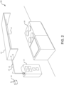
- Fig, 2 illustrates a kitchen fire suppression system 200 that may be used in accordance with one or more embodiments of the present technology.
- a fire suppression system 200 may be installed for appliance 205 (e.g., stove or other kitchen appliance).
- Fire suppression system 200 can include nozzle 210 in a fixed position relative to appliance 205.
- Additional components of the fire suppression system (described in more detail in Fig. 3 ) can be included in enclosure 215.
- enclosure 215 can include a cartridge containing a pressurized gas and an agent tank coupled to the cartridge.
- the pressurized gas within the cartridge may include, for example, Nitrogen or C02, depending on the application.
- the agent tank can have a fire suppression agent stored within.
- the suppression agent is typically housed at atmospheric pressure in the agent tank.
- the agent tank can be connected to distribution piping 220 providing a conduit that allows the fire suppression agent, when expelled from the agent tank, to flow from the agent tank to the nozzle.
- a release assembly inside enclosure 215 can be coupled to the cartridge and detection line 225.
- Detection line 225 can extend through hood 230 and may be enclosed. Detection line 225 can be designed to break or melt after reaching a temperature that may be indicative of a fire. As detection line 225 breaks, the release assembly is activated. Upon activation of the release assembly, the cartridge within enclosure 215 releases pressurized gas causing the fire suppression agent to expel from the agent tank through the distribution piping 220 to nozzle 210.
- one or more sensors and at least one communications module can be included with fire suppression system 200,
- the sensors can be used to measure a current state at the nozzle 210, the cartridge, the agent tank, the release assembly, or other component states (e.g., temperatures, pressures, flow rates, volumes, and the like).
- Communications module 235 is configured to receive measurements of the current state from the one or more sensors and transmit the current state to a remote monitoring platform.
- Communications module 235 is configured to receive a bypass signal to suppress an alarm within the fire suppression system. The suppression of the alarm allows a technician to service the fire suppression system without an alarm signal being generated and/or transmitted, and may also provide positive input that the system is being serviced.
- the communications module is a local processing unit.
- the bypass signal In response to the bypass signal, alarm notifications generated by the alarm are suppressed for a period of time (e.g., thirty minutes, one hour, two hours etc.).
- the bypass signal can include the period of time (e.g., as selected by a technician). In other embodiments, the period of time may be fixed (e.g., five minutes, ten, minutes, one hour, etc.).
- the alarm notifications can include internal and external alarm signals, and the communications module can be further configured to receive an activation signal to active the alarm, In response to the activation signal, the bypass of the alarm notifications can be removed.
- Local processing unit or communications module 235 can be further configured to determine whether the one or more sensors indicate that the fire suppression system is fully functional. Upon determining that the fire suppression system is not fully functional, the fire suppression system can generate an alert to the technician that the period of time the alarm notifications will be suppressed is about to expire. These alarm notifications can be sent via local processing unit or communications module 235 ⁇ e.g., using a short-range network or communications protocol), in some embodiments, local processing unit or communications module 235 can directly communicate the measurements of the current state of the one or more sensors to a gateway (not shown). The gateway, upon receiving the signals, can then transmit (e.g., using a cellular or IP-based network) the current state to a remote monitoring platform.
- a gateway not shown. The gateway, upon receiving the signals, can then transmit (e.g., using a cellular or IP-based network) the current state to a remote monitoring platform.
- the fire suppression system can include a local memory to record the current state from the one or more sensors over a period of time. Then, local processing unit or communications module 235 can transmit the current state over the period of time in batches to the monitoring platform. These transmissions may be prescheduled (e.g., every ten minutes, every hour, once a day, etc.) or event triggered. As one example, the system may send more frequent transmission upon determining that the appliance is in use (e.g. , based on temperature readings) and then send less frequent transmissions when the applicant is determined not to be in use (e.g. , in the middle of the night).
- Fig. 2 illustrates embodiments of the fire suppression system with respect to kitchen appliances
- the system can be used for the continuous monitoring and protection of one or more hazard areas of a vehicle.
- a hazard area can be an engine compartment, a wheel well, hydraulic equipment and system, a storage area for combustible materials, and/or other location of a vehicle.
- These systems may use a variety of different fire suppressing agents, such as, but not limited to heptafluoropropane and/or sodium bicarbonate.
- Some embodiments may Include multiple zones of protection each having different nozzles and sensors that allow for fire protection and/or prediction.
- Each of the zones may have a local processing unit or communications module ⁇ e.g., communication module 235) can transmit the current state over the period of time in batches to the monitoring platform or to a centralized processing unit that is responsible for the vehicle.
- Each of the nozzles can be connected via distribution piping to an agent tank and/or pressurized canister to allow for the distribution of the agent
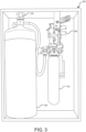
- Fig. 3 illustrates a set of components 30G of a fire suppression system that may be used in accordance with various embodiments of the present technology.
- the components of the fire suppression system within enclosure 215 can include cartridge 310 containing a pressurized gas (e.g., Nitrogen or CO2), agent tank 320 coupled to cartridge 310, and release assembly 330 coupled to the cartridge 310 and detection line 225 (shown in Fig. 2 ).
- Agent tank 320 can have stored within it a fire suppression agent.
- Agent tank 320 can be connected to distribution piping 220 providing a conduit that allows the fire suppression agent, when expelled from the agent tank 320, to flow from agent tank 320 to nozzle 210 via the distribution piping 220.
- Release assembly 330 can include one or more sensors (e.g., switches, accelerometers, scales, spring-based mechanism, etc.) to determine whether the cartridge is installed and to identify whether release assembly 330 is loaded or unloaded.
- sensors e.g., switches, accelerometers, scales, spring-based mechanism, etc.
- These sensors can be provided by a number of manufacturers and can be integrated into various points on the assembly or included as part of an aftermarket add-on kit. When these sensors (e.g., micro switches) are available, the system can monitor the outputs of these sensors as I/O points allowing the system to determine whether cartridge 310 is installed and whether release assembly 330 is loaded or unloaded.
- different logic can be provided, depending on whether the switches are normally open or normally closed.
- Some embodiments may not include switches (e.g., micro switches).
- other detection mechanisms can be used.
- cartridge 310 can be tethered and monitored for connectivity as well as a vertical state.
- Some embodiments can use a counter weighted or liquid metal switch mechanism.
- other embodiments could use accelerometers, gyros, or a bail switch.
- a sensor that can detect orientation (e.g., a bail switch) to the cartridge, the system can monitor the cartridge orientation.
- a vertical state e.g., normal installed position
- the switch can be installed/configured to be normally closed, but when removed and placed horizontally (they are cylinders with rounded bottoms so they are generally placed horizontally), it reports a normally open state.
- the system can be programmable to add a delay (e.g., one minutes, two minutes, five minutes, ten minutes, twenty minutes, or other amount of time) after which point the system may activate local visual or audible reminder (e.g., using a piezo, buzzer, LED, etc.) to remind a technician that cartridge 310 is still uninstalled.
- a delay e.g., one minutes, two minutes, five minutes, ten minutes, twenty minutes, or other amount of time
- the system may activate local visual or audible reminder (e.g., using a piezo, buzzer, LED, etc.) to remind a technician that cartridge 310 is still uninstalled.
- a spring-based mechanism can be used in some embodiments to measure the weight of agent tank 320. This measurement can be indicative of whether sufficient fire suppression agent is present within agent tank 320.
- nozzle 210 can be associated with a temperature sensor to measure a temperature at nozzle 210.
- detection line 225 When the fire suppression system is in an operating state, detection line 225 should have tension. During service, the tension on detection line 225 is often released and could be left in the maintenance state afterwards thus leaving the system inoperable.
- Embodiments of the present technology can monitor the tension on detection line 225 in a variety of ways, For example, a liquid metal or metal ball switch may be used in some embodiments.
- the liquid metal or metal ball switch can be affixed to an arming mechanism or part of the mechanical armature. The switch would be wired into the system as either a normally open or normally closed switch.
- Some embodiments may use a proximity probe or micro switch to determine whether detection line 225 is active.
- the proximity probe or micro switch may be affixed to the arming mechanism (micro switch) or at the loaded or unloaded position (proximity). The option for a normally open or normally closed switch would be necessary so that multiple system configurations could be monitored.
- some embodiments may use an extensometer or load cell to look at stretch or tension in the cable, in cases where springs are providing the tension on the line, the extensometer could be integrated into the spring ⁇ e.g. , much like a spring-based scale that fishermen use to weigh the fish they catch).
- the detection line state can be monitored and reported by the microprocessor. Just like the installed state of the cartridge, an alarm could be set locally on a time delay.
- Some embodiments can also verify whether a sufficient amount of agent is contained in cartridge 310. For example, when cartridge 310 has a tare weight that is significantly less than the weight when full with agent (e.g., less than 60%, 50%, 40%, etc.) an identification may be made that the agent is missing.
- a tare weight that is significantly less than the weight when full with agent (e.g., less than 60%, 50%, 40%, etc.) an identification may be made that the agent is missing.
- a tare weight that is significantly less than the weight when full with agent (e.g., less than 60%, 50%, 40%, etc.) an identification may be made that the agent is missing.
- a tare weight that is significantly less than the weight when full with agent (e.g., less than 60%, 50%, 40%, etc.) an identification may be made that the agent is missing.
- a tare weight that is significantly less than the weight when full with agent (e.g., less than 60%, 50%, 40%, etc.) an identification may be
- Some embodiments may use a spring-based system to detect the agent amount. For example, two different limits may be set creating three states that can be monitored by the fire suppression system.
- the "spring” can have a spring constant (K) that allows for small amounts of movement (e.g., 0.05600cm/kg (0,010 inches per lb)). In that case a 5.678 litre (1.5 gallon) tank will move the spring 0.3175 cm (1/8"), and the 11.36 litre (3-gallon) tank will move the spring 0.6350 (1 /4").
- K spring constant
- some embodiments can determine if the agent is below weight ⁇ e.g., no limit switch will be engaged), is at the 5.678 litre (1.5-gallon) limit but is below the 11.36 litre (3-gallon) limit (limit 1 engaged, limit 2 open), or has reached the 11.36 litre (3-gallon) limit (both limits engaged).
- Some embodiments may use a load cell on which agent tank 320 sits.
- One advantage of the load cell is that the system can get a better view of exactly how much agent is in agent tank 320 and whether that agent is leaking or not.
- the load cell can also act as a secondary validation for suppression release.
- the specific gravity of Ansulex (10.83 # gal), PRX (9.86 #/gal), and water (8.342 #/gal) are far enough apart that some embodiments may have encoded logic to provide details on the quantity of liquid in agent tank 320 and the contents. For example, an agent tank weighing 14.97kg (33 pounds) has to be a 3.785 litre (1 -gallon) Ansulex tank.
- An agent tank at 13.61kg (30 pounds) is probably an 11.36 litre (3-gallon) PRX, but it could be an 11.36 litre (3-gallon) Ansulex that is not completely full.
- An agent tank weighing 11.34kg (25 pounds) could be an 11.36 liter (3-gallon) tank of Ansulex or PRX that is low, or it could be an 11.36 liter (3-gallon) tank full of water.
- these can be indications of improperly filled tanks, which could automatically trigger and schedule an additional inspection (e.g., by a different technician).
- Either weighing system option lets the system validate if agent tanks are in place, if the agent is there, and whether we have a 5.678 or 11.36 liter (1.5- or 3.0-gallon) system (or some combination).
- kitchen hood systems in aggregate activate on a weekly, if not daily, basis, yet not ail fire suppression events are reported.
- Some system activations are the result of real fires, others are maintenance errors (technicians set them off inadvertently), and others are the result of improper or no maintenance (worn parts, wrong parts, non-OEM parts, etc.). Regardless of how the system is activated, a sequence of events can be triggered.
- the fire suppression system needs to be serviced; at a minimum, the suppression agent needs to be replaced, a new gas cartridge needs to be installed, and links and nozzles may need to be replaced, as well.
- the fire marshal and insurance company may need to review and approve this work, too. Sf cooking equipment was damaged, it needs to be serviced and or replaced, as well. Having the ability to capture the activation In real time can start the process sooner and will improve data gathering on the real number of system activations, as well as the causes behind them.
- the release and the puncture are highly identifiable metal-to-metal impacts, and the discharge produces a broader spectrum, longer duration and high-amplitude vibration. Accordingly, some embodiments may use microphones, vibration sensor, or other techniques to measure the acoustic signatures. Some embodiments, for example, may use an accelerometer placed on the cartridge, the puncture mechanism, the agent tank, or the discharge line (or any combination of these) to allow the system to determine various events and accurately identify a discharge.
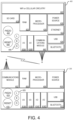
- Fig. 4 illustrates a set of components within a local processing unit 235 associated with a fire suppression system and a gateway unit 400 capable of receiving transmissions from one or more local processing units according to one or more embodiments of the present technology.
- local processing unit 235 and gateway unit 400 can be low-power, microprocessor-based devices focused solely on a particular application. These units may include processing units, memories, I/O capabilities, audible and visual signaling devices, and external communications capabilities.
- local processing unit 235 can include communications module 402, RAM 404, microprocessor 408, power source 408, USB 410, Bluetooth 412, I/O's 414A-414D, piezo 416, reset 418 and LEDs 420.
- Local processing unit 235 can communicate (e.g., wirelessly) with various sensors installed in a fire suppression system.
- gateway unit 400 can include Wi-Fi or cellular circuitry 422, SD card 424, RAM 426, microprocessor 428, power source 43Q, Ethernet 432, USB 434, Bluetooth 436, I/O's 438A-438B, communications module 440, piezo 442, reset 444, and/or LEDs 446.
- Microprocessors 406 and 428 can have unique identifiers (IDs) programmed or set at the manufacturing level The unique IDs can be used to link or associate local processing unit 235 or gateway unit 400 with customers, particular fire suppression systems, physical sites, and/or other information,
- Various embodiments of local processing unit 235 can allow a technician to configure a service delay timer. Since some systems are small (e.g., one or two tanks) and others are large (e.g., over a dozen tanks), one time delay does not work for all systems.
- the preconfigured timer starts. If the maintenance is completed within the timeframe, no warnings are issued. If the service takes longer, piezo 442 can start to beep.
- the technician has the option to reset/snooze the timer by depressing a button, if the technician does not reset the alarm and it is allowed to continue for a full period (e.g., 20-minute alarm is generated for another 20 minutes), then local processing unit 235 will notify an external server (e.g., monitoring platform. 130) that the fire suppression system is potentially disabled and a notification can be sent to facilities management, the technician, the remote monitoring platform, and others.
- an external server e.g., monitoring platform. 130
- the tension on the detection Sine may be released and the cartridge may be removed, in this instance, the system still works in the same capacity, except that the second device removal restarts the timer.
- the technician removes the cartridge, presumably weighs it, then a few minutes later releases the tension on the defection line, and that will restart the timer.
- both devices are back in their normal state, the maintenance state ends and the system is considered normal again.
- the microcontroller 408 in local processing unit 235 can search for a sequence of events and signatures.
- An example of one such sequence is the detection line tension is released, followed by a metal-to-metal vibration impact and a broader-range, extended vibration signature due to the discharge of gas.
- This signature is highly correlated to a discharge of gas. As such, when the system detects this signature indicative of a discharge of gas, the system will not know if this is a real fire, a test or human error without additional sensor data.
- the acoustic signature will change in both amplitude and frequency content (gas by itself has a different signature than gas and liquid combined).
- Low- and high-pass filtering techniques along with Fast Fourier Transforms, can be used to ID the event and determine if it was a full discharge or blowdown. The ability to identify this automatically allows the system to earmark the event as a test rather than an alarm (or vice versa).
- the system can inform the system owner and appropriate/assigned maintenance provider of the discharge via e-mail, text message, phone call or other communications protocols.
- the provisions can be made at the remote monitoring platform to define the discharge event as Real, Test or False Discharge (with additional details) after an inspection is performed. This allows the end user to begin recording a history, which also affords parent companies, insurance providers, and equipment manufacturers an opportunity to assess the probability and types of discharge events that are happening.
- Owners and system service providers can be notified within seconds of the discharge event.
- User profiles enable the end user to define his or her type or types of notification and when they occur ⁇ any time versus specific times). Accordingly, the notification capabilities are not solely limited to alarm or discharge notifications. Since the system is capable of identifying maintenance activity and/or normal states, the system can be configured to notify end users, technicians and customers of said states.
- Service events do not initially generate external notifications. If a service technician receives a local warning (piezo buzzing) and acknowledges the warning by depressing the button on the microcontroller, then no external warning is sent, if, however, the piezo 416 continues to sound for another predefined period of time, then we must presume that the technician has left the system in a non-operational state, and the system will send out external "System Inoperable" notifications, if an external line is not available, the system will attempt to send a message (e.g., via Bluetooth).
- a local warning piezo buzzing
- acknowledges the warning by depressing the button on the microcontroller then no external warning is sent, if, however, the piezo 416 continues to sound for another predefined period of time, then we must presume that the technician has left the system in a non-operational state, and the system will send out external "System Inoperable" notifications, if an external line is not available, the system will attempt to send a message (e.g., via Bluetooth).
- I/Os 414A-414D can be simple contact closure with a mechanical option to connect a switch to the normally open or normally closed terminals. This can help accommodate a variety of system configurations and may result in less field programming. Audible and visual warnings can be local (within the vicinity of the monitored system). For example, visual indicators may be board-based LED's 420, and audible would be a buzzer or piezo 416. Other embodiments may also include dry or wet contacts to provide binary alarm, warning, supervisory, trouble or other alerts to secondary fire, security, building automation or like systems on site.
- Local processing unit 235 and gateway unit 400 can have a variety of external communications, in some embodiments, these components can support serial or USB communications so that the device can be programmed, configured or interrogated.
- a local Ethernet port 432 (supporting POE) may also be available in some embodiments. Additional communications options may include the ability to add a daughter board for Wi-Fi or Cellular connectivity. This component can allow all data and events local to the system to a centralized server (e.g., remote monitoring platform 130).
- the electronics portions can support power management (light blue), input and output (grey), local storage (green-static and dynamic), communications (dark blue-standard, orange-optional) and MMI interface components (yellow). Since these fire suppression system are typically pure mechanical systems with no AC or DC power feed, power can be battery-based, with super caps and scavenging support. In the case of battery operation, Wi-Fi and Cellular communications may not feasible, so external notification may be limited to Bluetooth connectivity to the technician's phone or a local platform.
- gateway unit 400 may be closer to power and or network connections. As such, some embodiments may use a battery in the sensor package and one of the three power options noted above. The local processing unit may be battery powered, but if this is the only form of power, many types of external communications may quickly drain the battery. If gateway unit 400 is Installed in an enclosure (e.g. , enclosure 215 In Fig. 2 ) a variety of power options may be utilized including, but not limited to, the following options;
- some embodiments break the system into two parts: a small communications and sensor package.
- the Sink between the two components may be a lower frequency, low-bandwidth wireless link, thus allowing us to move the higher power components closer to a power source and an Ethernet connection or better ceil coverage.
- Some embodiment may use LoRa ® ⁇ https://www.lora-aiiiance.org/)- a low power wide area network that would provide an encrypted link from the fire suppression system to gateway unit 400.
- Gateway unit 400 has the potential to interface with multiple LoRa slaves so that one gateway unit may serve as the host to multiple hood systems at a large catering or hotel complex.
- some embodiments may add in other items to be monitored, like refrigeration, HV'AC, burglar alarms, sprinkler systems, fire extinguishers and fire alarm control panels, if necessary,
- Various embodiments of the LoRa-enabled system may include at least two major components: a small sensor package ⁇ at least one) and a larger gateway unit (only one).
- the sensor package transmits signals from local, low-power sensors back to gateway unit 400 where they are processed and forwarded on to an external server using the Ethernet, Wi-Fi or cellular connection. If 'additional systems are to be monitored at the site, a LoRa-based sensor package can be added and configured to communicate with gateway unit 400,
- FIG. 5 illustrates a set of components 500 within a monitoring platform in accordance with some embodiments of the present technology.
- monitoring platform 130 can include memory 505, one or more processors 510.
- GUI graphical user interface
- Each of these modules can be embodied as special-purpose hardware (e.g., one or more ASICS, PLDs, FPGAs, or the like), or as programmable circuitry (e.g., one or more microprocessors, microcontrollers, or the like) appropriately programmed with software and/or firmware, or as a combination of special-purpose hardware and programmable circuitry.
- Other embodiments of the present technology may include some, all, or none of these modules and components along with other modules, applications, and/or components, Still yet, some embodiments may incorporate two or more of these modules and components into a single module and/or associate a portion of the functionality of one or more of these modules with a different module.
- status module 520 and identification module 525 can be combined into a single module for determining the status of one or more fire suppression systems.
- Memory 505 can be any device, mechanism, or populated data structure used for storing information, In accordance with some embodiments of the present technology, memory 505 can encompass any type of, but is not limited to, volatile memory, nonvolatile memory and dynamic memory.
- memory 505 can be random access memory, memory storage devices, optical memory devices, media magnetic media, floppy disks, magnetic tapes, hard drives, SDRAM, RDRAM, DDR RAM, erasable programmable read-only memories (EPROMs), electrically erasable programmable read-only memories (EEPRGMs), compact disks, DVDs, and/or the like, in accordance with some embodiments, memory 505 may include one or more disk drives, flash drives, one or more databases, one or more tables, one or more files, local cache memories, processor cache memories, relational databases, flat databases, and/or the like.
- those of ordinary skill in the art will appreciate many additional devices and techniques for storing information that can be used as memory 505.
- Memory 505 may be used to store instructions for running one or more applications or modules on processors) 510.
- memory 505 could be used in one or more embodiments to house all or some of the instructions needed to execute the functionality of communications module 515, status module 520, identification module 525, data collection module 530, technician locator module 535, service request module 540, recordation module 545, analytics engine 550, prediction engine 555 and/or GUI generation module 560.
- an operating system can be used to provide a software package that is capable of managing the hardware resources of monitoring platform 130. The operating system can also provide common services for software applications running on processor(s) 510.
- Communications module 515 can be configured to manage and translate any requests from external devices (e.g., mobile devices 1 10A-1 10N, fire suppression systems, etc.) or from graphical user interfaces into a format needed by the destination component and/or system. Similarly, communications module 515 may be used to communicate between the system, modules, databases, or other components of monitoring platform 130 that use different communication protocols, data formats, or messaging routines. For example, in some embodiments, communications module 515 can receive measurements of the current state of one or more fire suppression systems Communications module 515 can be used to transmit status reports, alerts, logs, and other information to various devices.
- external devices e.g., mobile devices 1 10A-1 10N, fire suppression systems, etc.
- communications module 515 may be used to communicate between the system, modules, databases, or other components of monitoring platform 130 that use different communication protocols, data formats, or messaging routines. For example, in some embodiments, communications module 515 can receive measurements of the current state of one or more fire suppression systems Communications module 515 can be used to transmit status reports,
- Status module 520 can determine the status of one or more fire suppression systems. For example, status module 520 may use communications module 515 to directly request a status of a fire suppression system from one or more gateways or local processing units.
- Identification module 525 can be configured to receive sensor data generated by the fire suppression system. Using the received sensor data, identification module 525 can then identify an operational status of the fire suppression system. The operational status and/or the sensor data itself can then be recorded within a fire suppression profile in a database. As a result, the fire suppression profile can provide a history of the operational status of the fire suppression system over time.
- the operational status can include a functional status indicating that the fire suppression system will operate as expected, a maintenance status indicating that the fire suppression system is under maintenance, a discharge status indicating that the fire suppression system has been discharged, and an inoperative status indicating that the fire suppression system will not operate as expected.
- Data received via communications module 515 can be accessed by data collection module 530 for processing, formatting, and storage.
- Data collection module 530 can keep track of the last communication from each of the fire suppression systems and generate an alert if any fire suppression system fails to report on schedule (e.g. every minute, every five minutes, or other preset schedule).
- Data collection module 530 can also review the quality of the data received and identify any potential issues. For example, if a data set from a fire suppression system includes various sensor data, data collection module 530 can analyze the data to determine any erratic behavior or outers that may indicate that a sensor is beginning to fail.
- Technician locator module 535 can be configured to receive location and schedule updates from mobile devices associated with technicians.
- Sen/ice request module 540 can be configured to identify when the operational status of the fire suppression system is inoperative and identify an available technician using the technician locator.
- a technician is servicing a fire suppression system, he or she may use a computer application or a mobile application to report various findings, observations, parts replaced, and the like.
- recordation module 545 can record the information from the technician in the appropriate fire suppression profile,
- Analytics engine 550 can analyze the sensor data and generate a correlation model that Is predictive of when a discharge of the fire suppression system is likely, in some cases, analytics engine can use the sensor data as well as other types of information such as observations from the technicians during inspections.
- Prediction engine 555 can be configured to process the sensor data in real-time against the correlation model generated by the analytics engine 550 and generate an inspection request upon determination that the discharge of the fire suppression system is likely, In some embodiments, prediction engine 555 can also process the sensor data in real-time against the correlation model generated by analytics engine 550 and send a signal to the fire suppression system to automatically cutoff a gas line.
- Analytics engine 550 can also monitor the sensor data and generate other types of analytics such as for example one or more predictors that a fire is likely to occur.
- analytics engine 550 can be used includes analyzing the number of heat cycles of the appliance to create a dynamic service schedule for each location. As a result, low use locations (e.g., high schools) may have longer times between maintenance visits than higher use locations. This information can be used by service request module 540 to automatically schedule maintenance visits. As another example, analytics engine 550 can analyze actual system discharge data and the amount of damage (e.g., based on information collected from an insurance adjuster or other source) to identify system design issues. This information can be used to redesign systems and/or increase or reduce insurance premiums. Many additional examples exists of how analytics engines 550 and 555 may be utilized.
- the analytics engine 550 preferably includes a system evaluation module to determine system configuration.
- the module can analyze multiple fire suppression profiles and identify fire suppression system configurations that may have resulted in increased fire damage as compared to other fire suppression system configurations.
- the evaluation module is preferably configured to generate a recommendation for modifying the fire suppression system configurations that have experienced increased fire damage and thereby improve such profiles.
- GUI generation module 560 can generate one or more GUI screens that allow for interaction with a user.
- GUI generation module 560 can generate a graphical user interface allowing a user to set preferences, review reports, create profiles, set device constraints, and/or otherwise receive or convey information about device customization to the user.
- GUI generation module 580 can be configured to retrieve, from the database, the operational status from the multiple fire suppression profiles. Once the operational status has been retrieved, GUI generation module 580 can generate a graphical user interface allowing a user to see the operational status of any of the fire suppression profiles
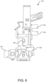
- Fig. 6 illustrates release assembly 330 with various sensors capable of communicating with a local processing unit in accordance with various embodiments of the present technology.
- a preloaded spring in release assembly 330 drives a pin into a seal on the pressurized cartridge (not shown in Fig. 6 ). This releases a high-pressure gas that travels through pressure regulator 810 and into the agent tank (not shown in Fig. 8 ). This forces the agent through the distribution piping and to one or more nozzles over the appliance or cooking area.
- Pin S20 indicates the current position of pin 620 that is capable of puncturing the seal on the pressurized cartridge; Typically, there is a position Indicating rod connected to pin 820, which is long enough that if extends out of release assembly 330 and lines up with an opening on the front cover of enclosure 215. In traditional systems, this has been the only indication that the system is loaded and/or discharged. Pin 820, nor the position indicating rod, does not provide any indication as to whether the pressurized cartridge is in place.
- Sensors 630 can be installed to monitor various states of the system, such as, but not limited to, loaded state of the detection line, presence of the pressurized cartridge, and the like.
- the sensors can be communicably connected to remote monitoring circuitry (e.g., a fire alarm control panel, a local processing unit, etc.) to provide an indication of whether the fire suppression system has discharged,
- release assembly 330 may have multiple additional sensors to aid in monitoring states of the fire suppression system.
- pressure regulator 610 may also include or have attached thereto an accelerometer. Signals created by the accelerometer can provide additional information about whether the canister has been discharged. While the location of the accelerometer(s) can vary, one advantage of placing one accelerometer on pressure regulator 610 is the direct contact with pin 620 and the cartridge. As a result, the accelerometer can monitor for any puncture or gas discharge by detecting local vibrations.
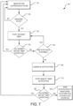
- Fig. 7 is flowchart illustrating a set of operations 700 for determining when to transmit a notification to a monitoring platform that the fire suppression system is not fully operative in accordance with one or more embodiments of the present technology.
- the operations illustrated in Fig. 7 may be performed by various components of the fire suppression system, including, but not limited to, one or more local processing units and/or gateway units associated with a fire suppression system.
- monitoring operation 710 can monitor a fire suppression system.
- a fire suppression system can transmit signals from various sensors associated with the fire suppression system. As these signals are received, determination operation 720 can determine if the system is in an abnormal state. Examples of abnormal states can include deactivation of the detection Sine, missing cartridge, incorrect or missing fire suppression agent, excessive heat, flow of a fire suppression agent, and the like.
- determination operation 720 determines that the fire suppression system is in a normal state
- determination operation 720 branches back to monitoring operation 710.
- determination operation 720 determines that the fire suppression system is in an abnormal state, then determination operation 720 branches to timing operation 730 where a timer is initiated.
- the amount of time set for the timer in timing operation 730 may be static (e.g. , thirty seconds, five minutes, etc.) or dependent on the type of abnormal state that is detected. For example, if the canister is missing, then timing operation 730 may set the timer for twenty minutes to give the technician time to remove, weigh and reinstall the cartridge. Similarly, timing operation 730 may set the timer to thirty seconds when a thermocouple detects a temperature above a specific threshold that could indicate a fire or steam cleaning of the hood assembly, in the event multiple abnormal states are detected, timing operation 730 may set the timer to the minimum time associate with the detected abnormalities or create a new time ⁇ e.g., an average or a weighted average).
- Expiration operation 740 monitors the abnormal states and the timer. Upon expiration of the timer, if the abnormal states have ail returned to normal, the expiration operation 740 branches to monitoring operation 710. if expiration operation 740 determines that the abnormal states have not ail returned to normal, the expiration operation 740 branches to state evaluation operation 750 where a determination is made as to whether one or more states have returned to normal. When state evaluation operation 750 determines that one or more states have returned to normal, state evaluation operation 750 branches to timing operation 730 where a new timer is set.
- state evaluation operation 750 determines that one or more states have not returned to normal, then state evaluation operation 750 can branch to generation operation 760 where one or more notifications can be sent to a technician and/or other party (e.g., building operator).
- the notifications may be sent via one or more communication channels. For example, lighting a display, text message, e-mail, automated phone call, fax, push notification, and/or the like.
- remote timing operation 770 starts a time for a specified period of time.
- the time set by remote timing operation 770 may be static or dynamic, as described above.
- remote timing operation 770 may set the timer, at least in part, based on whether or not a response was from the technician and/or a third party in response to the notifications.
- Clearing operation 780 can determine whether all the states have returned to normal before the timer expires. When clearing operation 780 determines ail states have returned to normal, then clearing operation 780 branches to monitoring operation 710. When clearing operation 780 determines that there is at least one remaining abnormal state, then clearing operation 780 branches to reporting operation 790 which sends one or more notifications to a monitoring platform (or other device) that the system is not operative or is discharging.
- Fig. 8 is a flowchart illustrating a set of operations 800 for sending notifications regarding the status of a fire suppression system in accordance with some embodiments of the present technology.
- the operations illustrated in Fig. 8 can be performed by various components of the fire suppression system including, but not limited to, one or more local processing units, gateway units, mobile devices, local gateway, monitoring platform, or one or more components (e.g. , processor(s) 406 or 428), engines, and/or modules associated with these devices.
- receiving operation 810 can receive one or more monitoring signals from the fire suppression system. These signals may include raw or processed sensor data.
- determination operation 820 can determine the state of the fire suppression system. Once the state of the fire suppression system has been determined, generation operation 830 can generate a corresponding notification. Transmission operation 840 can then transmit the notification to a technician, building supervisor, government authority, or other party.
- Fig. 9 is a flowchart illustrating a set of operations 900 for analyzing contents of a canister in accordance with various embodiments of the present technology.
- the operations illustrated in Fig. 9 can be performed by various components of the fire suppression system including, but not limited to, one or more local processing units, gateway units, mobile devices, monitoring platform, or one or more components (e.g., processors) 406 or 428), engines, and/or modules associated with these devices.
- receiving operation 910 can receive a notification of a canister change. This may be automatically generated, for example, in response to a signal generated by a sensor affiliated with a canister attachment point when the canister has been removed or is not present and has been replaced.
- Analysis operation 920 can generate a frequency analysis of the canister. For example, a hammer, trigger or other vibrations inducing mechanism can be used to knock the canister. A sensor at the other end of the canister can record the vibrations that have traveled through the canister.
- determination operation 930 a determination can be made as to whether the results of the frequency analysis match a desired profile.
- determination operation 930 can branch to identification operation 940 where an identification of the canister state can be made. For example, in some embodiments, identification operation 940 can determine if the canister is empty, only partially filled, filled with the wrong fire suppression agent, is the wrong size of canister, or the like.
- Logging operation 980 can log the failures.
- determination operation 930 determines that a match is present, determination operation 930 can branch to logging operation 970 where the match is recorded. Then, transmission operation 980 can transmit a notification of the match to a reporting application (e.g. that is running on a mobile device of a technician or on a remote monitoring platform).
- a reporting application e.g. that is running on a mobile device of a technician or on a remote monitoring platform.
- Fig. 10 illustrates an example of a sequence diagram 1000 illustrating message flow between various components of a fire suppression system with remote monitoring that may be used in one or more embodiments of the present technology.
- fire suppression system 1010 can send one or more system states (e.g. , sensor data) to a local gateway 1020.
- Local gateway 1020 then communicates the system states to local alarm system 1030 which can determine the system status by communicating directly with the local gateway.
- local alarm system Once a local alarm system has determined the system status, the local alarm can act. For example, the local alarm may shut off gas to an appliance, reroute air flow using the heating and ventilation system, open doors, sound alarms, and/or the like.
- the system status can be transmitted to monitoring platform 1040 where one or more notifications can be generated and transmitted to reporting application 1050 (e.g., associated with monitoring platform 040, running on one or more remote devices, displays, etc).
- reporting application 1050 e.g., associated with monitoring platform 040, running on one or more remote devices, displays, etc
- Fig. 1 1 is an example of a graphical user interface 1 100 that may be used in accordance with some embodiments of the present technology.
- graphical user interface 1 100 can include visualization area 11 10, notification area 1120, and interactive area 1130.
- Graphical user interface 1 00 can be running on a laptop or other mobile device and accessed by a technician performing maintenance or installing a fire suppression system. The laptop or other mobile device may connect directly (e.g., via Bluetooth, IP connection, etc.) to a local processing unit or indirectly via monitoring platform 130.
- Visualization area 1 1 10 can present an actual image or video of parts of the fire suppression system in order to allow the technician to quickly identify any potential issues
- visualization area 1110 may present a virtual representation of parts of the fire suppression system.
- the image presented, whether actual or virtualized, may highlight potential Issues to aid in review of the user. For example, if an agent tank is not vertical this could be highlighted with various overlays of different colors, movement showing that the agent tank needs to be inspected, presented in a magnified fashion, and the like.
- Notification area 1 120 can provide various notifications regarding the state of the system and any sensor measurements. This can include, for example, current temperatures, status of the cartridge, detection line, agent tank, agent within the agent tank, and/or whether the system is fully functional.
- Interactive area 113Q can allow the technician to select a location/fire suppression system with which to connect, order parts, take notes on the system, and/or the like.
- Some embodiments of the graphical user interface 1 100 can allow a user to suppress any alarms that would be generated while the system is under maintenance. In response to the request received via graphical user interface 100, one or more signals can be generated and transmitted to monitoring platform 130 and/or local processing unit to suppress alarm notifications during a period of time.
- graphical user interface 1100 may allow a technician to provide or confirm information regarding the system configuration. This information can then be analyzed to automatically validate the system installation. For example, if the technician (or sensors) identify an 11.36 liter (three gallon) tank with seventeen dedicated nozzles, a flag can be raised that the system may not operate as desired due ratio of tank sized to the number of nozzles. The system can alert the technician and/or other party regarding the potential system flaw.
- Fig. 12 is an example of graphical user interface screen 1200 visualizing data collected via a fire suppression system with remote monitoring in accordance with various embodiments of the present technology, in particular, graphical user interface 1200 shows temperature data from multiple days of the week overlaid for various areas that are being monitored. As this sensor data is collected and analyzed, various embodiments of the fire suppression system can identify trends and automatically generate notifications and interact with other building systems (e.g., gas lines, HVAC, etc.).
- other building systems e.g., gas lines, HVAC, etc.
- the system may conclude that the fryer and range should be turned off from 1AM to SAM on any given day.
- a notification can be sent to one or more parties (e.g., building manager, building security, etc).
- the fire suppression system may send a signal to automatically turn off an appliance, gas feed to the appliance, or electricity feed to the appliance.
- various embodiments of the fire suppression system may connect with a reservation system to determine if a private event or training session is occurring during the typically inactive time periods, if an event or training session has been scheduled, then the fire suppression system may take no action. If, however, no event or training session has been scheduled, the fire suppression system may generate notifications or send signals to reduce the heat being produced.
- the sensor data for multiple systems can be analyzed (e.g., via automated machine learning algorithms such, but not limited to, supervised learning algorithms, support vector machines, k-mean, principal component analysis, neural networks, deep learning and the like) to identify normal operating conditions and those features that may be predictive of when a discharge of the fire suppression system is likely.
- the fire suppression system e.g., the monitoring platform 130 ⁇ could generate, in response to conditions that are predictive of a discharge, an immediate inspection request.
- Fig. 13 is an example of graphical user interface 1300 that may be used in accordance with various embodiments of the present technology.
- a user can monitor multiple fire suppression systems via graphical user interface 1300 which provides a centralized reporting platform for companies having multiple properties with fire suppression systems in the embodiments illustrated in Fig. 13
- map 1310 is presented with multiple locators 1320 representing the location of the fire suppression systems.
- locators 1320 representing the location of the fire suppression systems.
- a callout 1330 is generated that presents specific system information. This can include identification information, such as, but not limited to, assigned names, MAC addresses, physical addresses, serial numbers, and the like. Other information from a fire suppression profile may be retrieved and presented within callout 1330.
- Fig. 14 is a block diagram illustrating an example machine representing the computer systemization of the fire suppression system with remote monitoring that can be used in accordance with one or more embodiments of the present technology.
- the fire suppression system controller 1400 may be in communication with entities, including one or more users 1425, client/terminal devices 1420 (e.g. , devices 11 QA-1 1 GN), user input devices 1405, peripheral devices 1410, optional coprocessor device(s) 1415 (e.g. , cryptographic processor devices), and networks 1430 (e.g., 120 in Fig. 1 ). Users may engage with the controller 1400 via terminal devices 1 20 over networks 1430.
- client/terminal devices 1420 e.g. , devices 11 QA-1 1 GN
- user input devices 1405 e.g., peripheral devices 1410
- optional coprocessor device(s) 1415 e.g. , cryptographic processor devices
- networks 1430 e.g., 120 in Fig. 1 .
- Users may engage with the controller 1400 via
- Computers may employ central processing unit (CPU) or processor to process information.
- Processors may include programmable general-purpose or special-purpose microprocessors, programmable controllers, application-specific integrated circuits (ASICs), programmable logic devices (PLDs), embedded components, a combination of such devices, and the like.
- ASICs application-specific integrated circuits
- PLDs programmable logic devices
- Processors execute program components in response to user- and/or system-generated requests, One or more of these components may be implemented in software, hardware, or both hardware and software.
- Processors pass instructions (e.g. , operational and data instructions) to enable various operations.
- the controller 1400 may include dock 1465, CPU 1470, memory such as read-only memory (ROM) 1485 and random access memory (RAM) 1480 and coprocessor 1475, among others. These controller components may be connected to a system bus 1480, and through the system bus 1480 to an interface bus 1435. Further, user input devices 1405, peripheral devices 1410, co-processor devices 1415, and the like, may be connected through the interface bus 1435 to the system bus 1460.
- the interface bus 1435 may be connected to a number of interface adapters, such as processor interface 1440, input/output interfaces (I/O) 1445, network interfaces 1450, storage interfaces 1455, and the like.
- Processor interface 1440 may facilitate communication between coprocessor devices 1415 and co-processor 1475. In one implementation, processor interface 1440 may expedite encryption and decryption of requests for data.
- I/O interfaces 1445 facilitate communication between user input devices 1405, peripheral devices 1410, co-processor devices 1415, and/or the like, and components of the controller 1400 using protocols such as those for handling audio, data, video interface, wireless transceivers, or the like (e.g., Bluetooth, IEEE 1394a-b, serial, universal serial bus (USB), Digital Visual interface (DVI), 802. H a/b/g/n/x, cellular, etc.).
- Network interfaces 1450 may be in communication with the network 1430. Through the network 1430, the controller 1400 may be accessible to remote terminal devices 1420.
- Network interfaces 1450 may use various wired and wireless connection protocols, such as, direct connect, Ethernet, wireless connection such as IEEE 802, 11 a-x, and the like.
- Examples of network 1430 include the Internet, Local Area Network (LAN), Metropolitan Area Network (MAN), a Wide Area Network (WAN), wireless network (e.g., using Wireless Application Protocol (WAP)), a secured custom connection, and the like.
- the network interfaces 1450 can include a firewall, which can, in some aspects, govern and/or manage permission to access/proxy data in a computer network, and track varying levels of trust between different machines and/or applications.
- the firewall can be any number of modules having any combination of hardware and/or software components able to enforce a predetermined set of access rights between a particular set of machines and applications, machines and machines, and/or applications and applications, for example, to regulate the flow of traffic and resource sharing between these varying entities,
- the firewall may additionally manage and/or have access to an access control list that details permissions, including, for example, the access and operation rights of an object by an individual, a machine, and/or an application, and the circumstances under which the permission rights stand.
- Other network security functions performed or included in the functions of the firewall can be, for example, but are not limited to, intrusion prevention, intrusion detection, next-generation firewall, personal firewall, etc., without deviating from the novel art of this disclosure.
- Storage interfaces 1455 may be in communication with a number of storage devices, such as storage devices 1490, removable disc devices, and the like.
- the storage interfaces 1455 may use various connection protocols, such as Serial Advanced Technology Attachment (SAT A), IEEE 1394, Ethernet, USB, and the like.
- SAT A Serial Advanced Technology Attachment
- IEEE 1394 IEEE 1394
- Ethernet Ethernet
- USB USB
- User input devices 1405 and peripheral devices 1410 may be connected to I/O interface 1445 and potentially other interfaces, buses and/or components.
- User input devices 1405 may include card readers, fingerprint readers, joysticks, keyboards, microphones, mouse, remote controls, retina readers, touch screens, sensors, and/or the like.
- Peripheral devices 1410 may include antenna, audio devices (e g., microphone, speakers, etc.), cameras, external processors, communication devices, radio frequency identifiers (RFIDs), scanners, printers, storage devices, transceivers, and/or the like
- Co-processor devices 1415 may be connected to the controller 1400 through interface bus 1435, and may include microcontrollers, processors, interfaces or other devices,
- Computer executable instructions and data may be stored in memory (e.g., registers, cache memory, random access memory, flash, etc.), which is accessible by processors. These stored instruction codes (e.g., programs) may engage the processor components, motherboard and/or other system components to perform desired operations.
- the controller 1400 may employ various forms of memory including on-chip CPU memory (e.g., registers), RA 1480, ROM 1485, and storage devices 1490.
- Storage devices 1490 may employ any number of tangible, non-transitor storage devices or systems such as fixed or removable magnetic disk drives, an optical drive, solid state memory devices and other processor-readable storage media.
- Computer-executable Instructions stored in the memory may Include the monitoring platform 130 having one or more program modules, such as routines, programs, objects, components, data structures, and so on that perform particular tasks or implement particular abstract data types.
- the memory may contain operating system (OS) component 1495, modules and other components, database tables, and the like. These modules/components may be stored and accessed from the storage devices 1490, including from external storage devices accessible through an interface bus 1435,
- the database components can store programs executed by the processor to process the stored data.
- the database components may be implemented in the form of a database that is relational, scalable and secure. Examples of such database include DB2, MySQL, Oracle, Sybase, and the like.
- the database may be Implemented using various standard data structures, such as an array, hash, list, stack, structured text file (e.g., XML), table, and/or the like. Such data structures may be stored in memory and/or in structured files.
- the controller 1400 may be implemented in distributed computing environments, where tasks or modules are performed by remote processing devices, which are linked through a communications network, such as a LAN, Wide Area Network ("WAN"), the Internet, and the like.
- a communications network such as a LAN, Wide Area Network ("WAN"), the Internet, and the like.
- program modules or subroutines may be located in both local and remote memory storage devices.
- Distributed computing may be employed to load-balance and/or aggregate resources for processing.
- aspects of the controller 1400 may be distributed electronically over the internet or over other networks (including wireless networks).
- portions of the fire suppression system may reside on a server computer, while corresponding portions reside on a client computer.
- Data structures and transmission of data particular to aspects of the controller 1400 are also encompassed within the scope of the disclosure.
- the words “comprise,” “comprising,” and the like are to be construed in an inclusive sense, as opposed to an exclusive or exhaustive sense; that is to say, in the sense of "including, but not limited to.”
- the terms “connected, “ “coupled,” or any variant thereof means any connection or coupling, either direct or indirect, between two or more elements; the coupling or connection between the elements can be physical, logical, or a combination thereof.
Description
- Various embodiments of the present technology generally relate to fire suppression systems. More specifically, the embodiments of the present technology relate to mechanical fire suppression systems and methods, remote monitoring of such systems, and analytics for such systems including predictive analysis of system performance.
- Mechanical fire suppression systems are pervasive in restaurants and have been used to protect kitchen and cooking appliances from the threat of a fire. Typically, these mechanical fire suppression systems work on a simple principle: a tensioned cable and a group of mechanical fuses or links are installed in the hood above the cooking surfaces and are connected to a trigger mechanism outside the hood area. Examples of fusible and mechanical links are shown in
U.S. Patent Application Publication No. 2007/0246234 andU.S. Patent Nos. 3,448,808 and3,772,499 . The mechanical fuses are unaffected by normal operating temperatures or low heat levels. However, when enough heat is generated by a fire, any fuse exposed to the excessive heat breaks and releases tension on the cable thereby activating the trigger mechanism. The activation of the trigger mechanism causes a cascading series of events, including the activation of a pressurized cartridge, the dispersion of a chemical suppression agent on the cooking surfaces, shutdown of the gas or electricity powering the cooking appliances, changes in air handling equipment, and potentially the activation of visual and audible alarms. An example of a restaurant fire suppression system is shown and described in the following publications from ANSUL® of Marinette. Wisconsin: (i) "Data Sheet: R-102 Restaurant Fire Suppression Systems," Form No. F -2004004-09 (2017); (ii) Owner's Guide: R-102™ Restaurant Fire Suppression System," Part No. 418127-03 (2008). - Due to the mechanical nature of these traditional fire suppression systems, there are some very rigorous inspection and maintenance requirements that must be routinely performed. One of the primary reasons for these regular inspection and maintenance requirements is that these systems are often exposed to a large amount of grease and oil, which can build up and detrimentally affect the operation of the fire suppression system. As a result, failure to maintain the system properly will most likely lead to issues, such as a false discharge (mechanical fuses eventually fail due to the excessive number of hot and cold cycles they are put through), or no discharge as the fuses or other parts of the cable are encased in hardened grease. Consequently, these systems need to be cleaned, inspected, and serviced regularly (e.g., on a three to six month cycle, depending on the environment).
- While regular inspection and maintenance is essential for proper operation of the fire suppression systems, there are many pitfalls in the maintenance regime that could result in improper operation of the fire suppression system. For example, as part of the maintenance of a hood, technicians typically disable the defection line and remove pressurized cartridges to allow the technician to properly inspect and work on the system with no chance of a false discharge. Unfortunately, the cartridge may not be reinstalled, the detection line may not be put back on Sine, or both. Left in any one of these states, the fire suppression system provides no suppression protection and is useless or at the least does not perform as desired.
US8378834 discloses a kitchen exhaust hood assembly having a fire suppression system with built-in redundancy and monitoring capabilities. - A first aspect of the present teachings provides a fire suppression system according to
claim 1. Various embodiments of the first aspect include the fire suppression system according to any of claim 2 to 14. - The accompanying drawings, which are incorporated herein and constitute part of this specification, illustrate exemplary embodiments of the invention, and together, with the general description given above and the detailed description given below, serve to explain the features of the invention. It should be understood that the preferred embodiments are not the totality of the invention but are examples of the invention as provided by the appended claims,
-
Fig. 1 illustrates an example of an operating environment for preferred fire suppression system and aspects thereof; -
Fig. 2 illustrates a preferred embodiment of kitchen fire suppression system; -
Fig. 3 illustrates a preferred set of components for use in the fire suppression system ofFig. 2 ; -
Fig. 4 illustrates a preferred embodiment of a local processing unit associated for use in the fire suppression system ofFig. 2 and a gateway unit capable of receiving transmissions from one or more local processing units; -
Fig. 5 illustrates a preferred embodiment of a preferred monitoring platform for use in the operating environment ofFig. 1 ; -
Fig, 6 illustrates a preferred embodiment of a release assembly for communication for use in set of components ofFig. 3 ; -
Fig, 7 is a flowchart illustrating a preferred set of operations for determining when to transmit a notification to the monitoring platform ofFig. 5 ; -
Fig. 8 is a flowchart illustrating a preferred set of operations for sending notifications regarding the status of the fire suppression system inFig. 2 ; -
Fig. 9 is a flowchart illustrating a preferred set of operations for analyzing contents of a canister used in the system ofFig. 2 ; -
Fig. 10 illustrates an example of a sequence diagram illustrating a preferred message flow between various components of a fire suppression system with remote monitoring; -
Fig. 11 is an example of a preferred graphical user interface that may be used with the system ofFig. 2 ; -
Fig. 12 is an example of a preferred graphical user interface screen illustrating plots of data collected via a fire suppression system with remote monitoring; -
Fig. 13 is another example of a preferred graphical user interface that may be used with a fire suppression system; and -
Fig. 14 is a preferred block diagram illustrating an example machine representing the computer systemization of a fire suppression system. -
Fig, 1 illustrates an example ofoperating environment 100 in which preferred embodiments of a mechanical fire protection system may be utilized. As Illustrated inFig. 1 ,operating environment 100 may include one or moremobile devices 110A-1 10N (e.g., a mobile phone, tablet computer, mobile media device, mobile gaming device, vehicle-based computer, wearable computing device, etc.),communications network 120, monitoring platform 130 (e.g., running on one or more remote servers), fire suppression systems located inbuildings 140A-140N,user management interface 160, and acustomer database 180. - Mobile devices 11 QA-1 1 Q and the fire suppression systems located in
buildings 140A-14QN can include network communication components that enable communication with remote servers (e.g., hosting monitoring platform 130) or other portable electronic devices by transmitting and receiving wireless signals using licensed, semi-licensed or unlicensed spectrum overcommunications network 120, In some cases,communications network 120 may comprise multiple networks, even multiple heterogeneous networks, such as one or more border networks, voice networks, broadband networks, service provider networks, Internet Service Provider (ISP) networks, and/or Public Switched Telephone Networks (PSTNs), interconnected via gateways operable to facilitate communications between and among the various networks.Communications network 120 can also include third-party communications networks such as a Global System for Mobile (GSM) mobile communications network, a code/time division multiple access (CD A TDMA) mobile communications network, a 3rd or 4th generation (3G/4G) mobile communications network (e.g. , Genera! Packet Radio Service (GPRS/EGPRS)), Enhanced Data rates for GSM Evolution (EDGE), Universal Mobile Telecommunications System (UMTS), or Long Term Evolution (LTE) network), or other communications network. - Those skilled In the art will appreciate that various other components {not shown) may be included in
mobile devices 1 10A-1 10N to enable network communication. For example, a mobile device may be configured to communicate over a GSM mobile telecommunications network. As a result, the mobile device or components of the fire suppression systems may include a Subscriber Identity Module (S M) card that stores an International Mobile Subscriber Identity (IMSi) number that is used to identify the mobile device on the GSM mobile communications network or other networks, for example, those employing 3G and/or 4G wireless protocols. If the mobile device or components of the fire suppression systems is configured to communicate over another communications network, the mobile device or components of the fire suppression systems may include other components that enable it to be identified on the other communications networks. - In some embodiments,
mobile devices 1 10A-1 10N or components of the fire suppression systems in buildings 14GA-14GN may include components that enable them to connect to a communications network using Generic Access Network (GA ) or Unlicensed Mobile Access (U A) standards and protocols. For example, a mobile device may include components that support Internet Protocol (IP)-based communication over a Wireless Local Area Network (WLAN) and components that enable communication with the telecommunications network over the IP-based WLAN.Mobile devices 1 10A-1 10N or components of the fire suppression systems may include one or more mobile applications that need to transfer data or check-in withmonitoring platform 130. - In some embodiments,
monitoring platform 130 can be configured to receive signals regarding the state of one or more fire suppressions systems. The signals can indicate the current status of a variety of system components. For example, in accordance with some embodiments, the signals can indicate whether or not the cartridge is installed, service state of the detection line, activation of the system, sensor measurements (e.g., temperature, accelerations, etc.), and the like, in some embodiments, the fire suppression systems can monitor and report the status of the cartridge using either existing micro switches or the physical position of the cartridge. The status of the detection line can be monitored and reported using existing micro switches, tension on the line, or the position of the mechanical components on the line. -
Monitoring platform 130 can provide a centralized reporting platform for companies having multiple properties with fire suppression systems. For example, a hotel chain or restaurant chain may desire to monitor multiple properties viamonitoring platform 130. This information can be stored in a database in one or more fire suppression profiles. Each of the fire suppression profiles can include a location of a fire suppression system, a fire suppression system identifier, a list of components of the fire suppression system, a list of sensors available on the fire suppression system, current and historical state information, contact information (e.g., phone numbers, mailing addresses, etc.), maintenance logs, and other information. By recording the maintenance logs, for example,monitoring platform 130 can create certifiable maintenance records to third parties (e.g., insurance companies, fire marshals, etc.) which can be stored incustomer database 160. - In some embodiments, the system identifier may be associated with some of the static information. For example, a first set of alphanumeric characters may represent the owner or business (e.g., a particular hotel chain), a second set of alphanumeric characters may represent a particular system configuration, and the like. , The following table illustrates some fire suppression profiles that may be recorded on the database.
System Identifier Current State Maintenance Log H17836007245 Active May 01, 2016 - Full Service November 12, 2015 - Full Service May 16, 2015 - Full Service System Identifier Current State Maintenance Log H231459A73nq Detection Line April 10, 2016 - Full Service Not Set October 12, 2015 - Full Service May 1, 2015 - System Installed A89438777T91 Under March 01, 2016 - Replaced thermocouple Maintenance February 12, 2016 - Full Service August 22, 2015 - System installed -
Fig, 2 illustrates a kitchenfire suppression system 200 that may be used in accordance with one or more embodiments of the present technology. As illustrated inFig. 2 , afire suppression system 200 may be installed for appliance 205 (e.g., stove or other kitchen appliance).Fire suppression system 200 can includenozzle 210 in a fixed position relative toappliance 205. Additional components of the fire suppression system (described in more detail inFig. 3 ) can be included inenclosure 215. For example,enclosure 215 can include a cartridge containing a pressurized gas and an agent tank coupled to the cartridge. The pressurized gas within the cartridge may include, for example, Nitrogen or C02, depending on the application. The agent tank can have a fire suppression agent stored within. The suppression agent is typically housed at atmospheric pressure in the agent tank. The agent tank can be connected to distribution piping 220 providing a conduit that allows the fire suppression agent, when expelled from the agent tank, to flow from the agent tank to the nozzle. - A release assembly inside
enclosure 215 can be coupled to the cartridge anddetection line 225.Detection line 225 can extend throughhood 230 and may be enclosed.Detection line 225 can be designed to break or melt after reaching a temperature that may be indicative of a fire. Asdetection line 225 breaks, the release assembly is activated. Upon activation of the release assembly, the cartridge withinenclosure 215 releases pressurized gas causing the fire suppression agent to expel from the agent tank through the distribution piping 220 tonozzle 210. - In accordance with various embodiments, one or more sensors and at least one communications module can be included with
fire suppression system 200, The sensors can be used to measure a current state at thenozzle 210, the cartridge, the agent tank, the release assembly, or other component states (e.g., temperatures, pressures, flow rates, volumes, and the like). -
Communications module 235 is configured to receive measurements of the current state from the one or more sensors and transmit the current state to a remote monitoring platform..Communications module 235 is configured to receive a bypass signal to suppress an alarm within the fire suppression system. The suppression of the alarm allows a technician to service the fire suppression system without an alarm signal being generated and/or transmitted, and may also provide positive input that the system is being serviced. In an example, the communications module is a local processing unit. - In response to the bypass signal, alarm notifications generated by the alarm are suppressed for a period of time (e.g., thirty minutes, one hour, two hours etc.). In some embodiments, the bypass signal can include the period of time (e.g., as selected by a technician). In other embodiments, the period of time may be fixed (e.g., five minutes, ten, minutes, one hour, etc.). The alarm notifications can include internal and external alarm signals, and the communications module can be further configured to receive an activation signal to active the alarm, In response to the activation signal, the bypass of the alarm notifications can be removed.
- Local processing unit or
communications module 235 can be further configured to determine whether the one or more sensors indicate that the fire suppression system is fully functional. Upon determining that the fire suppression system is not fully functional, the fire suppression system can generate an alert to the technician that the period of time the alarm notifications will be suppressed is about to expire. These alarm notifications can be sent via local processing unit or communications module 235 {e.g., using a short-range network or communications protocol), in some embodiments, local processing unit orcommunications module 235 can directly communicate the measurements of the current state of the one or more sensors to a gateway (not shown). The gateway, upon receiving the signals, can then transmit (e.g., using a cellular or IP-based network) the current state to a remote monitoring platform. - In some embodiments, the fire suppression system can include a local memory to record the current state from the one or more sensors over a period of time. Then, local processing unit or
communications module 235 can transmit the current state over the period of time in batches to the monitoring platform. These transmissions may be prescheduled (e.g., every ten minutes, every hour, once a day, etc.) or event triggered. As one example, the system may send more frequent transmission upon determining that the appliance is in use (e.g. , based on temperature readings) and then send less frequent transmissions when the applicant is determined not to be in use (e.g. , in the middle of the night). - While
Fig. 2 illustrates embodiments of the fire suppression system with respect to kitchen appliances, other embodiments of the present technology may be use other types of fire suppression systems. For example, the system can be used for the continuous monitoring and protection of one or more hazard areas of a vehicle. A hazard area can be an engine compartment, a wheel well, hydraulic equipment and system, a storage area for combustible materials, and/or other location of a vehicle. These systems may use a variety of different fire suppressing agents, such as, but not limited to heptafluoropropane and/or sodium bicarbonate. Some embodiments may Include multiple zones of protection each having different nozzles and sensors that allow for fire protection and/or prediction. Each of the zones may have a local processing unit or communications module {e.g., communication module 235) can transmit the current state over the period of time in batches to the monitoring platform or to a centralized processing unit that is responsible for the vehicle. Each of the nozzles can be connected via distribution piping to an agent tank and/or pressurized canister to allow for the distribution of the agent -
Fig. 3 illustrates a set of components 30G of a fire suppression system that may be used in accordance with various embodiments of the present technology. As illustrated InFig. 3 , the components of the fire suppression system withinenclosure 215 can includecartridge 310 containing a pressurized gas (e.g., Nitrogen or CO2),agent tank 320 coupled tocartridge 310, andrelease assembly 330 coupled to thecartridge 310 and detection line 225 (shown inFig. 2 ).Agent tank 320 can have stored within it a fire suppression agent.Agent tank 320 can be connected to distribution piping 220 providing a conduit that allows the fire suppression agent, when expelled from theagent tank 320, to flow fromagent tank 320 tonozzle 210 via thedistribution piping 220. -
Release assembly 330 can include one or more sensors (e.g., switches, accelerometers, scales, spring-based mechanism, etc.) to determine whether the cartridge is installed and to identify whetherrelease assembly 330 is loaded or unloaded. These sensors can be provided by a number of manufacturers and can be integrated into various points on the assembly or included as part of an aftermarket add-on kit. When these sensors (e.g., micro switches) are available, the system can monitor the outputs of these sensors as I/O points allowing the system to determine whethercartridge 310 is installed and whetherrelease assembly 330 is loaded or unloaded. For example, in some embodiments, different logic can be provided, depending on whether the switches are normally open or normally closed. - Some embodiments may not include switches (e.g., micro switches). However, other detection mechanisms can be used. For example,
cartridge 310 can be tethered and monitored for connectivity as well as a vertical state. Some embodiments can use a counter weighted or liquid metal switch mechanism. Still yet, other embodiments could use accelerometers, gyros, or a bail switch. By affixing a sensor that can detect orientation (e.g., a bail switch) to the cartridge, the system can monitor the cartridge orientation. While in a vertical state (e.g., normal installed position), the switch can be installed/configured to be normally closed, but when removed and placed horizontally (they are cylinders with rounded bottoms so they are generally placed horizontally), it reports a normally open state. - Since maintenance is a regular occurrence, some embodiments may not create an alarm immediately when
cartridge 310 is removed. As such, the system can be programmable to add a delay (e.g., one minutes, two minutes, five minutes, ten minutes, twenty minutes, or other amount of time) after which point the system may activate local visual or audible reminder (e.g., using a piezo, buzzer, LED, etc.) to remind a technician thatcartridge 310 is still uninstalled. - A spring-based mechanism can be used in some embodiments to measure the weight of
agent tank 320. This measurement can be indicative of whether sufficient fire suppression agent is present withinagent tank 320. In addition,nozzle 210 can be associated with a temperature sensor to measure a temperature atnozzle 210. - When the fire suppression system is in an operating state,
detection line 225 should have tension. During service, the tension ondetection line 225 is often released and could be left in the maintenance state afterwards thus leaving the system inoperable. Embodiments of the present technology can monitor the tension ondetection line 225 in a variety of ways, For example, a liquid metal or metal ball switch may be used in some embodiments. The liquid metal or metal ball switch can be affixed to an arming mechanism or part of the mechanical armature. The switch would be wired into the system as either a normally open or normally closed switch. - Some embodiments may use a proximity probe or micro switch to determine whether
detection line 225 is active. Again, the proximity probe or micro switch may be affixed to the arming mechanism (micro switch) or at the loaded or unloaded position (proximity). The option for a normally open or normally closed switch would be necessary so that multiple system configurations could be monitored. Still yet, some embodiments may use an extensometer or load cell to look at stretch or tension in the cable, in cases where springs are providing the tension on the line, the extensometer could be integrated into the spring {e.g. , much like a spring-based scale that fishermen use to weigh the fish they catch). In accordance with various embodiments, the detection line state can be monitored and reported by the microprocessor. Just like the installed state of the cartridge, an alarm could be set locally on a time delay. - Some embodiments can also verify whether a sufficient amount of agent is contained in
cartridge 310. For example, whencartridge 310 has a tare weight that is significantly less than the weight when full with agent (e.g., less than 60%, 50%, 40%, etc.) an identification may be made that the agent is missing. In a 5.678 litre (1.5-gallon) tank, approximately 5.670 kg (1 2.5 pounds) of agent is typically needed to fillagent tank 320; and in the 11.36 litre (3-gallon) tank approximately, 11.34 kg (25 pounds) of agent is typically needed to fillagent tank 320. - Some embodiments may use a spring-based system to detect the agent amount. For example, two different limits may be set creating three states that can be monitored by the fire suppression system. The "spring" can have a spring constant (K) that allows for small amounts of movement (e.g., 0.05600cm/kg (0,010 inches per lb)). In that case a 5.678 litre (1.5 gallon) tank will move the spring 0.3175 cm (1/8"), and the 11.36 litre (3-gallon) tank will move the spring 0.6350 (1 /4"). By placing limit switches at these distances, some embodiments can determine if the agent is below weight {e.g., no limit switch will be engaged), is at the 5.678 litre (1.5-gallon) limit but is below the 11.36 litre (3-gallon) limit (limit 1 engaged, limit 2 open), or has reached the 11.36 litre (3-gallon) limit (both limits engaged).
- Some embodiments may use a load cell on which
agent tank 320 sits. One advantage of the load cell is that the system can get a better view of exactly how much agent is inagent tank 320 and whether that agent is leaking or not. The load cell can also act as a secondary validation for suppression release. In addition, the specific gravity of Ansulex (10.83 # gal), PRX (9.86 #/gal), and water (8.342 #/gal) are far enough apart that some embodiments may have encoded logic to provide details on the quantity of liquid inagent tank 320 and the contents. For example, an agent tank weighing 14.97kg (33 pounds) has to be a 3.785 litre (1 -gallon) Ansulex tank. An agent tank at 13.61kg (30 pounds) is probably an 11.36 litre (3-gallon) PRX, but it could be an 11.36 litre (3-gallon) Ansulex that is not completely full. An agent tank weighing 11.34kg (25 pounds) could be an 11.36 liter (3-gallon) tank of Ansulex or PRX that is low, or it could be an 11.36 liter (3-gallon) tank full of water. As such, these can be indications of improperly filled tanks, which could automatically trigger and schedule an additional inspection (e.g., by a different technician). - Either weighing system option lets the system validate if agent tanks are in place, if the agent is there, and whether we have a 5.678 or 11.36 liter (1.5- or 3.0-gallon) system (or some combination). Statistically speaking) at a global level, kitchen hood systems in aggregate activate on a weekly, if not daily, basis, yet not ail fire suppression events are reported. Some system activations are the result of real fires, others are maintenance errors (technicians set them off inadvertently), and others are the result of improper or no maintenance (worn parts, wrong parts, non-OEM parts, etc.). Regardless of how the system is activated, a sequence of events can be triggered. There is the obvious event that the fire department must respond to, but following that, the kitchen and cooking equipment needs to be cleaned and inspected by the board of health. The fire suppression system needs to be serviced; at a minimum, the suppression agent needs to be replaced, a new gas cartridge needs to be installed, and links and nozzles may need to be replaced, as well. The fire marshal and insurance company may need to review and approve this work, too. Sf cooking equipment was damaged, it needs to be serviced and or replaced, as well. Having the ability to capture the activation In real time can start the process sooner and will improve data gathering on the real number of system activations, as well as the causes behind them.
- White some of the micro switches in the system could provide an indication that a fire suppression system has discharged, they may not be conclusive. For example, tension can be released on the detection line to change the fusible links without removing the gas cartridge, and this would mimic a characteristic of a discharge event. Some embodiments monitor this state as a possible supervisory alarm, so it can't serve as an indicator of both. During a discharge, though, the detection line tension may be released quickly, when a pressure seal is broken on the cartridge, and high-pressure gas escapes and forces the liquid agent through the piping and nozzles. All of this activity makes noise and has acoustic signatures: the release and the puncture are highly identifiable metal-to-metal impacts, and the discharge produces a broader spectrum, longer duration and high-amplitude vibration. Accordingly, some embodiments may use microphones, vibration sensor, or other techniques to measure the acoustic signatures. Some embodiments, for example, may use an accelerometer placed on the cartridge, the puncture mechanism, the agent tank, or the discharge line (or any combination of these) to allow the system to determine various events and accurately identify a discharge.
-
Fig. 4 illustrates a set of components within alocal processing unit 235 associated with a fire suppression system and agateway unit 400 capable of receiving transmissions from one or more local processing units according to one or more embodiments of the present technology. In accordance with various embodiments,local processing unit 235 andgateway unit 400 can be low-power, microprocessor-based devices focused solely on a particular application. These units may include processing units, memories, I/O capabilities, audible and visual signaling devices, and external communications capabilities. For example,local processing unit 235 can includecommunications module 402,RAM 404,microprocessor 408,power source 408,USB 410,Bluetooth 412, I/O's 414A-414D, piezo 416, reset 418 andLEDs 420.Local processing unit 235 can communicate (e.g., wirelessly) with various sensors installed in a fire suppression system. Similarly,gateway unit 400 can include Wi-Fi orcellular circuitry 422,SD card 424,RAM 426,microprocessor 428, power source 43Q,Ethernet 432,USB 434,Bluetooth 436, I/O's 438A-438B,communications module 440, piezo 442, reset 444, and/orLEDs 446. -
Microprocessors local processing unit 235 orgateway unit 400 with customers, particular fire suppression systems, physical sites, and/or other information, - Various embodiments of
local processing unit 235 can allow a technician to configure a service delay timer. Since some systems are small (e.g., one or two tanks) and others are large (e.g., over a dozen tanks), one time delay does not work for all systems. When the cartridge is removed, the preconfigured timer starts. If the maintenance is completed within the timeframe, no warnings are issued. If the service takes longer, piezo 442 can start to beep. The technician has the option to reset/snooze the timer by depressing a button, if the technician does not reset the alarm and it is allowed to continue for a full period (e.g., 20-minute alarm is generated for another 20 minutes), thenlocal processing unit 235 will notify an external server (e.g., monitoring platform. 130) that the fire suppression system is potentially disabled and a notification can be sent to facilities management, the technician, the remote monitoring platform, and others. - During service, the tension on the detection Sine may be released and the cartridge may be removed, in this instance, the system still works in the same capacity, except that the second device removal restarts the timer. For example, the technician removes the cartridge, presumably weighs it, then a few minutes later releases the tension on the defection line, and that will restart the timer. When both devices are back in their normal state, the maintenance state ends and the system is considered normal again.
- Upon system discharge, the
microcontroller 408 inlocal processing unit 235 can search for a sequence of events and signatures. An example of one such sequence is the detection line tension is released, followed by a metal-to-metal vibration impact and a broader-range, extended vibration signature due to the discharge of gas. This signature is highly correlated to a discharge of gas. As such, when the system detects this signature indicative of a discharge of gas, the system will not know if this is a real fire, a test or human error without additional sensor data. - In the case of tests where agent is not used (just a system blowdown), the acoustic signature will change in both amplitude and frequency content (gas by itself has a different signature than gas and liquid combined). Low- and high-pass filtering techniques, along with Fast Fourier Transforms, can be used to ID the event and determine if it was a full discharge or blowdown. The ability to identify this automatically allows the system to earmark the event as a test rather than an alarm (or vice versa).
- In the case of a real discharge, the system can inform the system owner and appropriate/assigned maintenance provider of the discharge via e-mail, text message, phone call or other communications protocols. The provisions can be made at the remote monitoring platform to define the discharge event as Real, Test or False Discharge (with additional details) after an inspection is performed. This allows the end user to begin recording a history, which also affords parent companies, insurance providers, and equipment manufacturers an opportunity to assess the probability and types of discharge events that are happening.
- Owners and system service providers can be notified within seconds of the discharge event. User profiles enable the end user to define his or her type or types of notification and when they occur {any time versus specific times). Accordingly, the notification capabilities are not solely limited to alarm or discharge notifications. Since the system is capable of identifying maintenance activity and/or normal states, the system can be configured to notify end users, technicians and customers of said states.
- Service events do not initially generate external notifications. If a service technician receives a local warning (piezo buzzing) and acknowledges the warning by depressing the button on the microcontroller, then no external warning is sent, if, however, the piezo 416 continues to sound for another predefined period of time, then we must presume that the technician has left the system in a non-operational state, and the system will send out external "System Inoperable" notifications, if an external line is not available, the system will attempt to send a message (e.g., via Bluetooth).
- I/
Os 414A-414D can be simple contact closure with a mechanical option to connect a switch to the normally open or normally closed terminals. This can help accommodate a variety of system configurations and may result in less field programming. Audible and visual warnings can be local (within the vicinity of the monitored system). For example, visual indicators may be board-based LED's 420, and audible would be a buzzer or piezo 416. Other embodiments may also include dry or wet contacts to provide binary alarm, warning, supervisory, trouble or other alerts to secondary fire, security, building automation or like systems on site. -
Local processing unit 235 andgateway unit 400 can have a variety of external communications, in some embodiments, these components can support serial or USB communications so that the device can be programmed, configured or interrogated. A local Ethernet port 432 (supporting POE) may also be available in some embodiments. Additional communications options may include the ability to add a daughter board for Wi-Fi or Cellular connectivity. This component can allow all data and events local to the system to a centralized server (e.g., remote monitoring platform 130). - The electronics portions can support power management (light blue), input and output (grey), local storage (green-static and dynamic), communications (dark blue-standard, orange-optional) and MMI interface components (yellow). Since these fire suppression system are typically pure mechanical systems with no AC or DC power feed, power can be battery-based, with super caps and scavenging support. In the case of battery operation, Wi-Fi and Cellular communications may not feasible, so external notification may be limited to Bluetooth connectivity to the technician's phone or a local platform.
- If the sensor package is installed in the
enclosure 215,gateway unit 400 may be closer to power and or network connections. As such, some embodiments may use a battery in the sensor package and one of the three power options noted above. The local processing unit may be battery powered, but if this is the only form of power, many types of external communications may quickly drain the battery. Ifgateway unit 400 is Installed in an enclosure (e.g. ,enclosure 215 InFig. 2 ) a variety of power options may be utilized including, but not limited to, the following options; - Power option #1 - Power over Ethernet. With this option, the unit could still use a battery (as a backup), but the Ethernet port could be used for power and hardwired communications.
- Power option #2 - Local Power. A wall wart power supply and an onboard battery (as backup) could be used,
- Power option #3 - Panel Power. Pulling 12 or 24 volts from the onsite fire alarm panel Is another option. With jurisdictions starting to require a link to and from the restaurant system to ihe fire alarm control panel, this option may be a viable option.
- Rather than put the entire system in the fire suppression system back box, some embodiments break the system into two parts: a small communications and sensor package. The Sink between the two components may be a lower frequency, low-bandwidth wireless link, thus allowing us to move the higher power components closer to a power source and an Ethernet connection or better ceil coverage.
- Some embodiment may use LoRa® {https://www.lora-aiiiance.org/)- a low power wide area network that would provide an encrypted link from the fire suppression system to
gateway unit 400.Gateway unit 400 has the potential to interface with multiple LoRa slaves so that one gateway unit may serve as the host to multiple hood systems at a large catering or hotel complex. In addition, some embodiments may add in other items to be monitored, like refrigeration, HV'AC, burglar alarms, sprinkler systems, fire extinguishers and fire alarm control panels, if necessary, - Various embodiments of the LoRa-enabled system may include at least two major components: a small sensor package {at least one) and a larger gateway unit (only one). The sensor package transmits signals from local, low-power sensors back to
gateway unit 400 where they are processed and forwarded on to an external server using the Ethernet, Wi-Fi or cellular connection. If 'additional systems are to be monitored at the site, a LoRa-based sensor package can be added and configured to communicate withgateway unit 400, -
Fig. 5 illustrates a set of components 500 within a monitoring platform in accordance with some embodiments of the present technology. According to the embodiments shown inFig. 5 ,monitoring platform 130 can includememory 505, one ormore processors 510.communications module 515,status module 520,identification module 525,data collection module 530,technician locator module 535,service request module 540,recordation module 545,analytics 550,prediction engine 555, and graphical user interface (GUI) generation module 580. Each of these modules can be embodied as special-purpose hardware (e.g., one or more ASICS, PLDs, FPGAs, or the like), or as programmable circuitry (e.g., one or more microprocessors, microcontrollers, or the like) appropriately programmed with software and/or firmware, or as a combination of special-purpose hardware and programmable circuitry. Other embodiments of the present technology may include some, all, or none of these modules and components along with other modules, applications, and/or components, Still yet, some embodiments may incorporate two or more of these modules and components into a single module and/or associate a portion of the functionality of one or more of these modules with a different module. For example, in one embodiment,status module 520 andidentification module 525 can be combined into a single module for determining the status of one or more fire suppression systems. -
Memory 505 can be any device, mechanism, or populated data structure used for storing information, In accordance with some embodiments of the present technology,memory 505 can encompass any type of, but is not limited to, volatile memory, nonvolatile memory and dynamic memory. For example,memory 505 can be random access memory, memory storage devices, optical memory devices, media magnetic media, floppy disks, magnetic tapes, hard drives, SDRAM, RDRAM, DDR RAM, erasable programmable read-only memories (EPROMs), electrically erasable programmable read-only memories (EEPRGMs), compact disks, DVDs, and/or the like, in accordance with some embodiments,memory 505 may include one or more disk drives, flash drives, one or more databases, one or more tables, one or more files, local cache memories, processor cache memories, relational databases, flat databases, and/or the like. In addition, those of ordinary skill in the art will appreciate many additional devices and techniques for storing information that can be used asmemory 505. -
Memory 505 may be used to store instructions for running one or more applications or modules on processors) 510. For example,memory 505 could be used in one or more embodiments to house all or some of the instructions needed to execute the functionality ofcommunications module 515,status module 520,identification module 525,data collection module 530,technician locator module 535,service request module 540,recordation module 545,analytics engine 550,prediction engine 555 and/orGUI generation module 560. While not shown inFig. 5 , in some embodiments, an operating system can be used to provide a software package that is capable of managing the hardware resources ofmonitoring platform 130. The operating system can also provide common services for software applications running on processor(s) 510. -
Communications module 515 can be configured to manage and translate any requests from external devices (e.g.,mobile devices 1 10A-1 10N, fire suppression systems, etc.) or from graphical user interfaces into a format needed by the destination component and/or system. Similarly,communications module 515 may be used to communicate between the system, modules, databases, or other components ofmonitoring platform 130 that use different communication protocols, data formats, or messaging routines. For example, in some embodiments,communications module 515 can receive measurements of the current state of one or more fire suppressionsystems Communications module 515 can be used to transmit status reports, alerts, logs, and other information to various devices. -
Status module 520 can determine the status of one or more fire suppression systems. For example,status module 520 may usecommunications module 515 to directly request a status of a fire suppression system from one or more gateways or local processing units.Identification module 525 can be configured to receive sensor data generated by the fire suppression system. Using the received sensor data,identification module 525 can then identify an operational status of the fire suppression system. The operational status and/or the sensor data itself can then be recorded within a fire suppression profile in a database. As a result, the fire suppression profile can provide a history of the operational status of the fire suppression system over time. Sn accordance with some embodiments, the operational status can include a functional status indicating that the fire suppression system will operate as expected, a maintenance status indicating that the fire suppression system is under maintenance, a discharge status indicating that the fire suppression system has been discharged, and an inoperative status indicating that the fire suppression system will not operate as expected. - Data received via
communications module 515 can be accessed bydata collection module 530 for processing, formatting, and storage.Data collection module 530 can keep track of the last communication from each of the fire suppression systems and generate an alert if any fire suppression system fails to report on schedule (e.g. every minute, every five minutes, or other preset schedule).Data collection module 530 can also review the quality of the data received and identify any potential issues. For example, if a data set from a fire suppression system includes various sensor data,data collection module 530 can analyze the data to determine any erratic behavior or outers that may indicate that a sensor is beginning to fail. -
Technician locator module 535 can be configured to receive location and schedule updates from mobile devices associated with technicians. Sen/ice request module 540 can be configured to identify when the operational status of the fire suppression system is inoperative and identify an available technician using the technician locator. As a technician is servicing a fire suppression system, he or she may use a computer application or a mobile application to report various findings, observations, parts replaced, and the like. As this information is transmitted tomonitoring platform 130,recordation module 545 can record the information from the technician in the appropriate fire suppression profile, -
Analytics engine 550 can analyze the sensor data and generate a correlation model that Is predictive of when a discharge of the fire suppression system is likely, in some cases, analytics engine can use the sensor data as well as other types of information such as observations from the technicians during inspections.Prediction engine 555 can be configured to process the sensor data in real-time against the correlation model generated by theanalytics engine 550 and generate an inspection request upon determination that the discharge of the fire suppression system is likely, In some embodiments,prediction engine 555 can also process the sensor data in real-time against the correlation model generated byanalytics engine 550 and send a signal to the fire suppression system to automatically cutoff a gas line.Analytics engine 550 can also monitor the sensor data and generate other types of analytics such as for example one or more predictors that a fire is likely to occur. - One example of how
analytics engine 550 can be used includes analyzing the number of heat cycles of the appliance to create a dynamic service schedule for each location. As a result, low use locations (e.g., high schools) may have longer times between maintenance visits than higher use locations. This information can be used byservice request module 540 to automatically schedule maintenance visits. As another example,analytics engine 550 can analyze actual system discharge data and the amount of damage (e.g., based on information collected from an insurance adjuster or other source) to identify system design issues. This information can be used to redesign systems and/or increase or reduce insurance premiums. Many additional examples exists of howanalytics engines - In a preferred embodiment of the
analytics engine 550 preferably includes a system evaluation module to determine system configuration. In a preferred embodiment, the module can analyze multiple fire suppression profiles and identify fire suppression system configurations that may have resulted in increased fire damage as compared to other fire suppression system configurations. Moreover, the evaluation module is preferably configured to generate a recommendation for modifying the fire suppression system configurations that have experienced increased fire damage and thereby improve such profiles. -
GUI generation module 560 can generate one or more GUI screens that allow for interaction with a user. In at least one embodiment,GUI generation module 560 can generate a graphical user interface allowing a user to set preferences, review reports, create profiles, set device constraints, and/or otherwise receive or convey information about device customization to the user. For example, in some embodiments, GUI generation module 580 can be configured to retrieve, from the database, the operational status from the multiple fire suppression profiles. Once the operational status has been retrieved, GUI generation module 580 can generate a graphical user interface allowing a user to see the operational status of any of the fire suppression profiles -
Fig. 6 illustratesrelease assembly 330 with various sensors capable of communicating with a local processing unit in accordance with various embodiments of the present technology. When the detection line is activated, a preloaded spring inrelease assembly 330 drives a pin into a seal on the pressurized cartridge (not shown inFig. 6 ). This releases a high-pressure gas that travels throughpressure regulator 810 and into the agent tank (not shown inFig. 8 ). This forces the agent through the distribution piping and to one or more nozzles over the appliance or cooking area. - Pin S20 indicates the current position of
pin 620 that is capable of puncturing the seal on the pressurized cartridge; Typically, there is a position Indicating rod connected to pin 820, which is long enough that if extends out ofrelease assembly 330 and lines up with an opening on the front cover ofenclosure 215. In traditional systems, this has been the only indication that the system is loaded and/or discharged.Pin 820, nor the position indicating rod, does not provide any indication as to whether the pressurized cartridge is in place. - Sensors 630 (e.g., switches) can be installed to monitor various states of the system, such as, but not limited to, loaded state of the detection line, presence of the pressurized cartridge, and the like. The sensors can be communicably connected to remote monitoring circuitry (e.g., a fire alarm control panel, a local processing unit, etc.) to provide an indication of whether the fire suppression system has discharged,
- While not illustrated in
Fig. 6 ,release assembly 330 may have multiple additional sensors to aid in monitoring states of the fire suppression system. For example,pressure regulator 610 may also include or have attached thereto an accelerometer. Signals created by the accelerometer can provide additional information about whether the canister has been discharged. While the location of the accelerometer(s) can vary, one advantage of placing one accelerometer onpressure regulator 610 is the direct contact withpin 620 and the cartridge. As a result, the accelerometer can monitor for any puncture or gas discharge by detecting local vibrations. -
Fig. 7 is flowchart illustrating a set ofoperations 700 for determining when to transmit a notification to a monitoring platform that the fire suppression system is not fully operative in accordance with one or more embodiments of the present technology. In some embodiments, the operations illustrated inFig. 7 may be performed by various components of the fire suppression system, including, but not limited to, one or more local processing units and/or gateway units associated with a fire suppression system. - As illustrated in
Fig. 7 ,monitoring operation 710 can monitor a fire suppression system. For example, a fire suppression system can transmit signals from various sensors associated with the fire suppression system. As these signals are received,determination operation 720 can determine if the system is in an abnormal state. Examples of abnormal states can include deactivation of the detection Sine, missing cartridge, incorrect or missing fire suppression agent, excessive heat, flow of a fire suppression agent, and the like. Whendetermination operation 720 determines that the fire suppression system is in a normal state,determination operation 720 branches back tomonitoring operation 710. Whendetermination operation 720 determines that the fire suppression system is in an abnormal state, thendetermination operation 720 branches to timingoperation 730 where a timer is initiated. - The amount of time set for the timer in
timing operation 730 may be static (e.g. , thirty seconds, five minutes, etc.) or dependent on the type of abnormal state that is detected. For example, if the canister is missing, then timingoperation 730 may set the timer for twenty minutes to give the technician time to remove, weigh and reinstall the cartridge. Similarly, timingoperation 730 may set the timer to thirty seconds when a thermocouple detects a temperature above a specific threshold that could indicate a fire or steam cleaning of the hood assembly, in the event multiple abnormal states are detected,timing operation 730 may set the timer to the minimum time associate with the detected abnormalities or create a new time {e.g., an average or a weighted average). -
Expiration operation 740 monitors the abnormal states and the timer. Upon expiration of the timer, if the abnormal states have ail returned to normal, theexpiration operation 740 branches tomonitoring operation 710. ifexpiration operation 740 determines that the abnormal states have not ail returned to normal, theexpiration operation 740 branches tostate evaluation operation 750 where a determination is made as to whether one or more states have returned to normal. Whenstate evaluation operation 750 determines that one or more states have returned to normal,state evaluation operation 750 branches to timingoperation 730 where a new timer is set. Whenstate evaluation operation 750 determines that one or more states have not returned to normal, thenstate evaluation operation 750 can branch togeneration operation 760 where one or more notifications can be sent to a technician and/or other party (e.g., building operator). The notifications may be sent via one or more communication channels. For example, lighting a display, text message, e-mail, automated phone call, fax, push notification, and/or the like. - Once the notifications have been generated, then
remote timing operation 770 starts a time for a specified period of time. Again, the time set byremote timing operation 770 may be static or dynamic, as described above. As one additional example,remote timing operation 770 may set the timer, at least in part, based on whether or not a response was from the technician and/or a third party in response to the notifications.Clearing operation 780 can determine whether all the states have returned to normal before the timer expires. When clearingoperation 780 determines ail states have returned to normal, then clearingoperation 780 branches tomonitoring operation 710. When clearingoperation 780 determines that there is at least one remaining abnormal state, then clearingoperation 780 branches to reportingoperation 790 which sends one or more notifications to a monitoring platform (or other device) that the system is not operative or is discharging. -
Fig. 8 is a flowchart illustrating a set ofoperations 800 for sending notifications regarding the status of a fire suppression system in accordance with some embodiments of the present technology. The operations illustrated inFig. 8 can be performed by various components of the fire suppression system including, but not limited to, one or more local processing units, gateway units, mobile devices, local gateway, monitoring platform, or one or more components (e.g. , processor(s) 406 or 428), engines, and/or modules associated with these devices. As illustrated inFig. 8 , receivingoperation 810 can receive one or more monitoring signals from the fire suppression system. These signals may include raw or processed sensor data. Using the monitoring signals,determination operation 820 can determine the state of the fire suppression system. Once the state of the fire suppression system has been determined,generation operation 830 can generate a corresponding notification.Transmission operation 840 can then transmit the notification to a technician, building supervisor, government authority, or other party. -
Fig. 9 is a flowchart illustrating a set ofoperations 900 for analyzing contents of a canister in accordance with various embodiments of the present technology. The operations illustrated inFig. 9 can be performed by various components of the fire suppression system including, but not limited to, one or more local processing units, gateway units, mobile devices, monitoring platform, or one or more components (e.g., processors) 406 or 428), engines, and/or modules associated with these devices. As illustrated inFig. 9 , receivingoperation 910 can receive a notification of a canister change. This may be automatically generated, for example, in response to a signal generated by a sensor affiliated with a canister attachment point when the canister has been removed or is not present and has been replaced. -
Analysis operation 920 can generate a frequency analysis of the canister. For example, a hammer, trigger or other vibrations inducing mechanism can be used to knock the canister. A sensor at the other end of the canister can record the vibrations that have traveled through the canister. Duringdetermination operation 930, a determination can be made as to whether the results of the frequency analysis match a desired profile. Whendetermination operation 930 determines that a match is not present,determination operation 930 can branch toidentification operation 940 where an identification of the canister state can be made. For example, in some embodiments,identification operation 940 can determine if the canister is empty, only partially filled, filled with the wrong fire suppression agent, is the wrong size of canister, or the like. This can be done, for example, by matching the frequency analysis against a variety of different profiles or for particular features (e.g. , peaks at certain frequencies) of the frequency analysis. Depending on the results, additional tests may be selected or a request for a technician/third-party verification of the canister can be generatedOuting verification operation 950.Logging operation 980 can log the failures. - When
determination operation 930 determines that a match is present,determination operation 930 can branch tologging operation 970 where the match is recorded. Then,transmission operation 980 can transmit a notification of the match to a reporting application (e.g. that is running on a mobile device of a technician or on a remote monitoring platform). -
Fig. 10 illustrates an example of a sequence diagram 1000 illustrating message flow between various components of a fire suppression system with remote monitoring that may be used in one or more embodiments of the present technology. As illustrated inFig. 10 ,fire suppression system 1010 can send one or more system states (e.g. , sensor data) to alocal gateway 1020.Local gateway 1020 then communicates the system states tolocal alarm system 1030 which can determine the system status by communicating directly with the local gateway. Once a local alarm system has determined the system status, the local alarm can act. For example, the local alarm may shut off gas to an appliance, reroute air flow using the heating and ventilation system, open doors, sound alarms, and/or the like. The system status can be transmitted tomonitoring platform 1040 where one or more notifications can be generated and transmitted to reporting application 1050 (e.g., associated with monitoring platform 040, running on one or more remote devices, displays, etc). -
Fig. 1 1 is an example of agraphical user interface 1 100 that may be used in accordance with some embodiments of the present technology. As illustrated inFig 1 ,graphical user interface 1 100 can include visualization area 11 10,notification area 1120, andinteractive area 1130.Graphical user interface 1 00 can be running on a laptop or other mobile device and accessed by a technician performing maintenance or installing a fire suppression system. The laptop or other mobile device may connect directly (e.g., via Bluetooth, IP connection, etc.) to a local processing unit or indirectly viamonitoring platform 130. -
Visualization area 1 1 10 can present an actual image or video of parts of the fire suppression system in order to allow the technician to quickly identify any potential issues, in some embodiments,visualization area 1110 may present a virtual representation of parts of the fire suppression system. The image presented, whether actual or virtualized, may highlight potential Issues to aid in review of the user. For example, if an agent tank is not vertical this could be highlighted with various overlays of different colors, movement showing that the agent tank needs to be inspected, presented in a magnified fashion, and the like. -
Notification area 1 120 can provide various notifications regarding the state of the system and any sensor measurements. This can include, for example, current temperatures, status of the cartridge, detection line, agent tank, agent within the agent tank, and/or whether the system is fully functional. Interactive area 113Q can allow the technician to select a location/fire suppression system with which to connect, order parts, take notes on the system, and/or the like. Some embodiments of thegraphical user interface 1 100 can allow a user to suppress any alarms that would be generated while the system is under maintenance. In response to the request received viagraphical user interface 100, one or more signals can be generated and transmitted tomonitoring platform 130 and/or local processing unit to suppress alarm notifications during a period of time. - In accordance with some embodiments,
graphical user interface 1100 may allow a technician to provide or confirm information regarding the system configuration. This information can then be analyzed to automatically validate the system installation. For example, if the technician (or sensors) identify an 11.36 liter (three gallon) tank with seventeen dedicated nozzles, a flag can be raised that the system may not operate as desired due ratio of tank sized to the number of nozzles. The system can alert the technician and/or other party regarding the potential system flaw. -
Fig. 12 is an example of graphicaluser interface screen 1200 visualizing data collected via a fire suppression system with remote monitoring in accordance with various embodiments of the present technology, in particular,graphical user interface 1200 shows temperature data from multiple days of the week overlaid for various areas that are being monitored. As this sensor data is collected and analyzed, various embodiments of the fire suppression system can identify trends and automatically generate notifications and interact with other building systems (e.g., gas lines, HVAC, etc.). - For example, from the data illustrated in
Fig. 12 , the system may conclude that the fryer and range should be turned off from 1AM to SAM on any given day. As such, when the fire suppression system detects that the fryer or range is still producing heat during these periods, a notification can be sent to one or more parties (e.g., building manager, building security, etc). In some embodiments, the fire suppression system may send a signal to automatically turn off an appliance, gas feed to the appliance, or electricity feed to the appliance. As another example, various embodiments of the fire suppression system may connect with a reservation system to determine if a private event or training session is occurring during the typically inactive time periods, if an event or training session has been scheduled, then the fire suppression system may take no action. If, however, no event or training session has been scheduled, the fire suppression system may generate notifications or send signals to reduce the heat being produced. - As discussed above, the sensor data for multiple systems can be analyzed (e.g., via automated machine learning algorithms such, but not limited to, supervised learning algorithms, support vector machines, k-mean, principal component analysis, neural networks, deep learning and the like) to identify normal operating conditions and those features that may be predictive of when a discharge of the fire suppression system is likely. The fire suppression system (e.g., the monitoring platform 130} could generate, in response to conditions that are predictive of a discharge, an immediate inspection request.
-
Fig. 13 is an example ofgraphical user interface 1300 that may be used in accordance with various embodiments of the present technology. In accordance with various embodiments, a user can monitor multiple fire suppression systems viagraphical user interface 1300 which provides a centralized reporting platform for companies having multiple properties with fire suppression systems in the embodiments illustrated inFig. 13 ,map 1310 is presented withmultiple locators 1320 representing the location of the fire suppression systems. When a user selects one oflocators 1320, acallout 1330 is generated that presents specific system information. This can include identification information, such as, but not limited to, assigned names, MAC addresses, physical addresses, serial numbers, and the like. Other information from a fire suppression profile may be retrieved and presented withincallout 1330. This can include current and historical state information, sensor data, streaming video, recent images (e.g., that update periodically or upon request), a list of components of the fire suppression system, a list of sensors available on the fire suppression system, contact information (e.g., phone numbers, mailing addresses, etc.), maintenance logs, and other information. Accordingly color coded pins or bubbles can be defined so the high-level status oflocations 1320 can be determined visually. For example, a discharged system may use a red marker while a system undergoing maintenance may be marked by blue and one deemed inoperable might be black or yellow. - Aspects and implementations of the fire suppression system of the disclosure have been described in the general context of various steps and operations. A variety of these steps and operations may be performed by hardware components or may be embodied in computer-executable instructions, which may be used to cause a general-purpose or special-purpose processor (e.g. , in a computer, server, or other computing device) programmed with the instructions to perform the steps or operations. For example, the steps or operations may be performed by a combination of hardware, software, and/or firmware.
-
Fig. 14 is a block diagram illustrating an example machine representing the computer systemization of the fire suppression system with remote monitoring that can be used in accordance with one or more embodiments of the present technology. The firesuppression system controller 1400 may be in communication with entities, including one or more users 1425, client/terminal devices 1420 (e.g. , devices 11 QA-1 1 GN), user input devices 1405,peripheral devices 1410, optional coprocessor device(s) 1415 (e.g. , cryptographic processor devices), and networks 1430 (e.g., 120 inFig. 1 ). Users may engage with thecontroller 1400 viaterminal devices 1 20 overnetworks 1430. - Computers may employ central processing unit (CPU) or processor to process information. Processors may include programmable general-purpose or special-purpose microprocessors, programmable controllers, application-specific integrated circuits (ASICs), programmable logic devices (PLDs), embedded components, a combination of such devices, and the like. Processors execute program components in response to user- and/or system-generated requests, One or more of these components may be implemented in software, hardware, or both hardware and software. Processors pass instructions (e.g. , operational and data instructions) to enable various operations.
- The
controller 1400 may includedock 1465,CPU 1470, memory such as read-only memory (ROM) 1485 and random access memory (RAM) 1480 andcoprocessor 1475, among others. These controller components may be connected to asystem bus 1480, and through thesystem bus 1480 to an interface bus 1435. Further, user input devices 1405,peripheral devices 1410,co-processor devices 1415, and the like, may be connected through the interface bus 1435 to the system bus 1460. The interface bus 1435 may be connected to a number of interface adapters, such asprocessor interface 1440, input/output interfaces (I/O) 1445,network interfaces 1450,storage interfaces 1455, and the like. -
Processor interface 1440 may facilitate communication betweencoprocessor devices 1415 andco-processor 1475. In one implementation,processor interface 1440 may expedite encryption and decryption of requests for data. Input/output (I/O) interfaces 1445 facilitate communication between user input devices 1405,peripheral devices 1410,co-processor devices 1415, and/or the like, and components of thecontroller 1400 using protocols such as those for handling audio, data, video interface, wireless transceivers, or the like (e.g., Bluetooth, IEEE 1394a-b, serial, universal serial bus (USB), Digital Visual interface (DVI), 802. H a/b/g/n/x, cellular, etc.).Network interfaces 1450 may be in communication with thenetwork 1430. Through thenetwork 1430, thecontroller 1400 may be accessible to remoteterminal devices 1420.Network interfaces 1450 may use various wired and wireless connection protocols, such as, direct connect, Ethernet, wireless connection such as IEEE 802, 11 a-x, and the like. - Examples of
network 1430 include the Internet, Local Area Network (LAN), Metropolitan Area Network (MAN), a Wide Area Network (WAN), wireless network (e.g., using Wireless Application Protocol (WAP)), a secured custom connection, and the like. The network interfaces 1450 can include a firewall, which can, in some aspects, govern and/or manage permission to access/proxy data in a computer network, and track varying levels of trust between different machines and/or applications. The firewall can be any number of modules having any combination of hardware and/or software components able to enforce a predetermined set of access rights between a particular set of machines and applications, machines and machines, and/or applications and applications, for example, to regulate the flow of traffic and resource sharing between these varying entities, The firewall may additionally manage and/or have access to an access control list that details permissions, including, for example, the access and operation rights of an object by an individual, a machine, and/or an application, and the circumstances under which the permission rights stand. Other network security functions performed or included in the functions of the firewall can be, for example, but are not limited to, intrusion prevention, intrusion detection, next-generation firewall, personal firewall, etc., without deviating from the novel art of this disclosure. -
Storage interfaces 1455 may be in communication with a number of storage devices, such asstorage devices 1490, removable disc devices, and the like. The storage interfaces 1455 may use various connection protocols, such as Serial Advanced Technology Attachment (SAT A), IEEE 1394, Ethernet, USB, and the like. - User input devices 1405 and
peripheral devices 1410 may be connected to I/O interface 1445 and potentially other interfaces, buses and/or components. User input devices 1405 may include card readers, fingerprint readers, joysticks, keyboards, microphones, mouse, remote controls, retina readers, touch screens, sensors, and/or the like.Peripheral devices 1410 may include antenna, audio devices (e g., microphone, speakers, etc.), cameras, external processors, communication devices, radio frequency identifiers (RFIDs), scanners, printers, storage devices, transceivers, and/or the like,Co-processor devices 1415 may be connected to thecontroller 1400 through interface bus 1435, and may include microcontrollers, processors, interfaces or other devices, - Computer executable instructions and data may be stored in memory (e.g., registers, cache memory, random access memory, flash, etc.), which is accessible by processors. These stored instruction codes (e.g., programs) may engage the processor components, motherboard and/or other system components to perform desired operations. The
controller 1400 may employ various forms of memory including on-chip CPU memory (e.g., registers),RA 1480,ROM 1485, andstorage devices 1490.Storage devices 1490 may employ any number of tangible, non-transitor storage devices or systems such as fixed or removable magnetic disk drives, an optical drive, solid state memory devices and other processor-readable storage media. Computer-executable Instructions stored in the memory may Include themonitoring platform 130 having one or more program modules, such as routines, programs, objects, components, data structures, and so on that perform particular tasks or implement particular abstract data types. For example, the memory may contain operating system (OS)component 1495, modules and other components, database tables, and the like. These modules/components may be stored and accessed from thestorage devices 1490, including from external storage devices accessible through an interface bus 1435, - The database components can store programs executed by the processor to process the stored data. The database components may be implemented in the form of a database that is relational, scalable and secure. Examples of such database include DB2, MySQL, Oracle, Sybase, and the like. Alternatively, the database may be Implemented using various standard data structures, such as an array, hash, list, stack, structured text file (e.g., XML), table, and/or the like. Such data structures may be stored in memory and/or in structured files.
- The
controller 1400 may be implemented in distributed computing environments, where tasks or modules are performed by remote processing devices, which are linked through a communications network, such as a LAN, Wide Area Network ("WAN"), the Internet, and the like. In a distributed computing environment, program modules or subroutines may be located in both local and remote memory storage devices. Distributed computing may be employed to load-balance and/or aggregate resources for processing. Alternatively, aspects of thecontroller 1400 may be distributed electronically over the internet or over other networks (including wireless networks). Those skilled in the relevant art(s) will recognize that portions of the fire suppression system may reside on a server computer, while corresponding portions reside on a client computer. Data structures and transmission of data particular to aspects of thecontroller 1400 are also encompassed within the scope of the disclosure. - Unless the context clearly requires otherwise, throughout the description and the claims, the words "comprise," "comprising," and the like are to be construed in an inclusive sense, as opposed to an exclusive or exhaustive sense; that is to say, in the sense of "including, but not limited to." As used herein, the terms "connected, " "coupled," or any variant thereof means any connection or coupling, either direct or indirect, between two or more elements; the coupling or connection between the elements can be physical, logical, or a combination thereof. Additionally, the words "herein," "above," "below," and words of similar import, when used in this application, refer to this application as a whole and not to any particular portions of this application, Where the context permits, words in the above Detailed Description using the singular or plural number may also include the plural or singular number respectively. The word "or," in reference to a list of two or more items, covers all of the following interpretations of the word: any of the items in the list, all of the items in the list, and any combination of the items in the list.
- The above Detailed Description of examples of the technology is not intended to be exhaustive or to limit the technology to the precise form disclosed above. While specific examples for the technology are described above for Illustrative purposes, various modifications are possible within the scope of the technology, as those skilled in the relevant art will recognize. For example, while processes or blocks are presented in a given order, alternative implementations may perform routines having steps, or employ systems having blocks, in a different order, and some processes or blocks may be deleted, moved, added, subdivided, combined, and/or modified to provide alternative or subcombinations. Each of these processes or blocks may be implemented in a variety of different ways. Also, while processes or blocks are at times shown as being performed in series, these processes or blocks may instead be performed or implemented in parallel, or may be performed at different times. Further, any specific numbers noted herein are only examples: alternative implementations may employ differing values or ranges.
- The teachings of the technology provided herein can be applied to other systems, not necessarily the system described above. The elements and acts of the various examples described above can be combined to provide further implementations of the technology. Some alternative implementations of the technology may include not only additional elements to those implementations noted above, but also may include fewer elements.
Claims (14)
- A fire suppression system (200) comprising:a nozzle (210);a cartridge (310) containing a pressurized gas;an agent tank (320) coupled to the cartridge (310) and having stored within a fire suppression agent;distribution piping (220) providing a conduit that allows the fire suppression agent when expelled from the agent tank to flow from the agent tank (320) to the nozzle (210);a release assembly (330) coupled to the cartridge (310),wherein, upon activation of the release assembly (330), the cartridge (310) releases the pressurized gas causing the fire suppression agent to expel from the agent tank (320) through the distribution piping (220) to the nozzle;one or more sensors to measure a current state at the nozzle (210), the cartridge (310), the agent tank (320), or the release assembly (330); and
a communications module (402) to receive measurements of the current state from the one or more sensors and transmit the current state to a remote monitoring platform (130), andreceive a bypass signal to suppress an alarm within the fire suppression system (200) allowing a technician to service the fire suppression system (200); andsuppress, in response to the bypass signal, alarm notifications generated by the alarm during a period of time. - The fire suppression system (200) of claim 1, wherein the alarm notifications include internal and external alarm signals and the communications module (402) is further configured to;receive an activation signal to activate the alarm; andremove, in response to the activation signal, the suppression of the alarm notifications.
- The fire suppression system (200) of claim 1, wherein the communications module (402) is further configured to:determine whether the one or more sensors indicate that the fire suppression system 9200) is fully functional; andgenerate, upon determining that the fire suppression system (200) is not fully functional, an alert to the technician that the period of time the alarm notifications will be suppressed is about to expire.
- The fire suppression system (200) of claim 1, wherein the communications module (402) uses a short-range network to communicate the measurements of the current state from the one or more sensors, and the system further comprises a gateway (40)) to receive, using the short-range network, communications from the communications module (402) and transmit using a cellular or IP-based network the current state to the remote monitoring platform (130).
- The fire suppression system (200) of claim 1, further comprising a local memory to record the current state from the one or more sensors over a period of time and wherein the communications module (402) transmits the current state over the period of time in batches.
- The fire suppression system (200) of claim 1, wherein the release assembly (330) is coupled to a detection line (225) and the one or more sensors include:a first micro switch to determine whether the cartridge (310) is installed;a second micro switch associated with the release assembly to identify whether the release assembly (330) is loaded or unloaded; anda spring-based mechanism to measure the weight of the agent tank (320) indicating whether sufficient fire suppression agent is present within the agent tank (320).
- The fire suppression system (200) of claim 1, wherein the nozzle (210) is associated with a temperature sensor to measure a temperature at the nozzle (210).
- The fire suppression system (200) of claim 1, further comprising an application running on a computing device, the application comprising:a graphical user interface generation module (560) to generate a graphical user Interface allowing a first user of the application to view the current state from the one or more sensors; anda suppression module to generate signals that when received by the communications module (402) suppress alarm notifications during a period of time.
- The fire suppression system (200) of claim 1, wherein the nozzle (210) is fixed relative to an appliance.
- The fire suppression system (200) of claim 1, wherein the nozzle (210) is one of multiple nozzles.
- The fire suppression system (200) of claim 10, further comprising multiple zones each having one or more of the multiple nozzles located therein.
- The fire suppression system (200) of claim 11, wherein each of the multiple nozzles is associated with an appliance within a vehicle, a wheel well of the vehicle, a storage compartment of the vehicle, a hydraulic system of the vehicle, or a passenger compartment of the vehicle.
- A fire suppression system (200) of claim 1, the system further comprising:a local processing unit (235) comprising:a processor (408);a memory (404); andthe communications module (402), the communications module (402) being under the control of the processor, configured to receive measurements of the current state from the one or more sensors, and determine, based on the measurements from the one or more sensors, an operational status of the fire suppression system (200), and transmit at least the operational status of the fire suppression system (200) to an external device.
- The fire suppression system (200) of claim 13, wherein the local processing unit (235) further comprises a speaker or buzzer to generate an audible alarm when the operational status of the fire suppression system indicates a discharge state or an inoperable state.
Applications Claiming Priority (4)
| Application Number | Priority Date | Filing Date | Title |
|---|---|---|---|
| US201662435636P | 2016-12-16 | 2016-12-16 | |
| US15/382,391 US10695600B2 (en) | 2016-12-16 | 2016-12-16 | Monitoring platform for mechanical fire suppression systems |
| US15/382,322 US10478651B2 (en) | 2016-12-16 | 2016-12-16 | Sensor integration in mechanical fire suppression systems |
| PCT/US2017/066757 WO2018112385A2 (en) | 2016-12-16 | 2017-12-15 | Systems and methods for mechanical fire suppression, monitoring and analytics |
Publications (2)
| Publication Number | Publication Date |
|---|---|
| EP3554651A2 EP3554651A2 (en) | 2019-10-23 |
| EP3554651B1 true EP3554651B1 (en) | 2023-07-26 |
Family
ID=62559399
Family Applications (1)
| Application Number | Title | Priority Date | Filing Date |
|---|---|---|---|
| EP17829416.1A Active EP3554651B1 (en) | 2016-12-16 | 2017-12-15 | Fire suppression system |
Country Status (3)
| Country | Link |
|---|---|
| EP (1) | EP3554651B1 (en) |
| ES (1) | ES2952687T3 (en) |
| WO (1) | WO2018112385A2 (en) |
Families Citing this family (13)
| Publication number | Priority date | Publication date | Assignee | Title |
|---|---|---|---|---|
| US11285347B2 (en) | 2018-06-08 | 2022-03-29 | Tyco Fire Products Lp | Cartridge monitoring system |
| WO2020112216A1 (en) * | 2018-11-30 | 2020-06-04 | Carrier Corporation | Fire suppression system remote monitoring |
| CN109760605A (en) * | 2018-12-29 | 2019-05-17 | 亿江(北京)科技发展有限公司 | A kind of vehicle-mounted multi-service gateway of internet of things and wisdom fire-fighting system |
| CN111488955A (en) * | 2019-01-29 | 2020-08-04 | 深圳富桂精密工业有限公司 | Fire control terminal, fire control server and fire control monitoring device |
| WO2021084480A1 (en) * | 2019-10-31 | 2021-05-06 | Tyco Fire Products Lp | Cartridge monitoring system and coupler |
| US20230036315A1 (en) * | 2020-01-06 | 2023-02-02 | Tyco Fire Products Lp | Electronic fire detection system for use in restaurants |
| US20210220685A1 (en) * | 2020-01-21 | 2021-07-22 | Carrier Corporation | Cartridge replacement aid |
| US20210220683A1 (en) * | 2020-01-21 | 2021-07-22 | Carrier Corporation | Cartridge status indicator |
| CN112141846A (en) * | 2020-09-29 | 2020-12-29 | 深圳市海和科技股份有限公司 | Elevator based on MCU and wireless communication system |
| WO2022204764A1 (en) * | 2021-04-01 | 2022-10-06 | Steve Metlitzky | A fire extinguisher discharge detection device |
| RU2760106C1 (en) * | 2021-04-09 | 2021-11-22 | Общество с ограниченной ответственностью "Эпотос-К" | Automatic fire alarm and fire extinguishing control system in mobile vehicles and its elements |
| CN113287950B (en) * | 2021-05-25 | 2022-04-01 | 安庆船用电器有限责任公司 | Marine electric fryer with automatic alarm function |
| US11765604B2 (en) | 2021-12-16 | 2023-09-19 | T-Mobile Usa, Inc. | Providing configuration updates to wireless telecommunication networks |
Family Cites Families (5)
| Publication number | Priority date | Publication date | Assignee | Title |
|---|---|---|---|---|
| US3448808A (en) | 1967-03-21 | 1969-06-10 | Kidde & Co Walter | Fire extinguishing system and control apparatus |
| US3772499A (en) | 1973-02-08 | 1973-11-13 | Gen Electric | Fryer circuit for use with a hood circuit having fire protection apparatus |
| US6029751A (en) * | 1997-02-07 | 2000-02-29 | Ford; Wallace Wayne | Automatic fire suppression apparatus and method |
| US20070246234A1 (en) | 2006-04-20 | 2007-10-25 | William Vegso | Fire suppression system |
| US8378834B1 (en) * | 2008-05-02 | 2013-02-19 | Captive-Aire Systems, Inc. | Kitchen hood assembly with fire suppression control system including multiple monitoring circuits |
-
2017
- 2017-12-15 WO PCT/US2017/066757 patent/WO2018112385A2/en unknown
- 2017-12-15 ES ES17829416T patent/ES2952687T3/en active Active
- 2017-12-15 EP EP17829416.1A patent/EP3554651B1/en active Active
Also Published As
| Publication number | Publication date |
|---|---|
| ES2952687T3 (en) | 2023-11-03 |
| WO2018112385A2 (en) | 2018-06-21 |
| EP3554651A2 (en) | 2019-10-23 |
| WO2018112385A3 (en) | 2018-07-26 |
Similar Documents
| Publication | Publication Date | Title |
|---|---|---|
| EP3554651B1 (en) | Fire suppression system | |
| US11819721B2 (en) | Sensor integration in mechanical fire suppression systems | |
| US10695600B2 (en) | Monitoring platform for mechanical fire suppression systems | |
| AU2019236723B2 (en) | Method and apparatus for determining maintenance needs and validating the installation of an alarm system | |
| US9830804B2 (en) | Methods, apparatuses, and computer program products for implementing situational control processes | |
| JP5893376B2 (en) | Systems and methods for providing toxic gas exposure compliance and warnings for health care and plant maintenance and warning of toxic gas exposure | |
| JP2020113269A (en) | Internet promotion fire prevention system and real time monitoring system | |
| US8026791B2 (en) | Methods, apparatuses, and computer program products for implementing remote control processes | |
| US10438457B2 (en) | System and method to remotely detect alarms | |
| EP3270242B1 (en) | Systems and methods for predicting and displaying site safety metrics | |
| US20230034481A1 (en) | Iot based fire and disaster management systems and methods | |
| CN102870144A (en) | Aspirating environmental sensor with webserver and email notification | |
| CN102682565A (en) | Fire protection and security integrated intelligent video monitoring system suitable for open space | |
| US11004326B2 (en) | System and method for monitoring a location | |
| MacLeod et al. | Reliability of fire (point) detection system in office buildings in Australia–A fault tree analysis | |
| US20080319768A1 (en) | Methods, apparatuses, and computer program products for device management | |
| AU2018354716A1 (en) | Fire detection system, automatic data capture, remote testing, analysis, apparatus and methods | |
| JP2017120491A (en) | Security operation support system and security device | |
| Rahman et al. | An integrated hardware prototype for monitoring gas leaks, fires, and remote control via mobile application | |
| CN212990273U (en) | Ganbaosu production system with explosion-proof detection function | |
| JP6811627B2 (en) | Monitoring system and center equipment | |
| CN112179418A (en) | Anti-explosion processing system and method for Ganbaosu production line | |
| JP2009032293A (en) | Remote monitoring system for electronic component manufacturing device | |
| JP2010066966A (en) | Method of guiding reporting and measuring at discovering of abnormal phenomena, using ic chip mounted card | |
| JP2018147148A (en) | Terminal, maintenance management system, program for terminal, terminal with module, and module adapter |
Legal Events
| Date | Code | Title | Description |
|---|---|---|---|
| STAA | Information on the status of an ep patent application or granted ep patent |
Free format text: STATUS: UNKNOWN |
|
| STAA | Information on the status of an ep patent application or granted ep patent |
Free format text: STATUS: THE INTERNATIONAL PUBLICATION HAS BEEN MADE |
|
| PUAI | Public reference made under article 153(3) epc to a published international application that has entered the european phase |
Free format text: ORIGINAL CODE: 0009012 |
|
| STAA | Information on the status of an ep patent application or granted ep patent |
Free format text: STATUS: REQUEST FOR EXAMINATION WAS MADE |
|
| 17P | Request for examination filed |
Effective date: 20190628 |
|
| AK | Designated contracting states |
Kind code of ref document: A2 Designated state(s): AL AT BE BG CH CY CZ DE DK EE ES FI FR GB GR HR HU IE IS IT LI LT LU LV MC MK MT NL NO PL PT RO RS SE SI SK SM TR |
|
| AX | Request for extension of the european patent |
Extension state: BA ME |
|
| DAV | Request for validation of the european patent (deleted) | ||
| DAX | Request for extension of the european patent (deleted) | ||
| STAA | Information on the status of an ep patent application or granted ep patent |
Free format text: STATUS: EXAMINATION IS IN PROGRESS |
|
| 17Q | First examination report despatched |
Effective date: 20221212 |
|
| REG | Reference to a national code |
Ref country code: DE Ref legal event code: R079 Ref document number: 602017071888 Country of ref document: DE Free format text: PREVIOUS MAIN CLASS: A62C0035020000 Ipc: A62C0037000000 Ref country code: DE Ref legal event code: R079 Free format text: PREVIOUS MAIN CLASS: A62C0035020000 Ipc: A62C0037000000 |
|
| GRAP | Despatch of communication of intention to grant a patent |
Free format text: ORIGINAL CODE: EPIDOSNIGR1 |
|
| STAA | Information on the status of an ep patent application or granted ep patent |
Free format text: STATUS: GRANT OF PATENT IS INTENDED |
|
| RIC1 | Information provided on ipc code assigned before grant |
Ipc: A62C 35/02 20060101ALI20230310BHEP Ipc: A62C 35/13 20060101ALI20230310BHEP Ipc: A62C 35/00 20060101ALI20230310BHEP Ipc: A62C 3/07 20060101ALI20230310BHEP Ipc: A62C 3/00 20060101ALI20230310BHEP Ipc: A62C 37/50 20060101ALI20230310BHEP Ipc: A62C 37/36 20060101ALI20230310BHEP Ipc: A62C 37/00 20060101AFI20230310BHEP |
|
| INTG | Intention to grant announced |
Effective date: 20230330 |
|
| GRAS | Grant fee paid |
Free format text: ORIGINAL CODE: EPIDOSNIGR3 |
|
| GRAA | (expected) grant |
Free format text: ORIGINAL CODE: 0009210 |
|
| STAA | Information on the status of an ep patent application or granted ep patent |
Free format text: STATUS: THE PATENT HAS BEEN GRANTED |
|
| RAP3 | Party data changed (applicant data changed or rights of an application transferred) |
Owner name: TYCO FIRE PRODUCTS LP |
|
| AK | Designated contracting states |
Kind code of ref document: B1 Designated state(s): AL AT BE BG CH CY CZ DE DK EE ES FI FR GB GR HR HU IE IS IT LI LT LU LV MC MK MT NL NO PL PT RO RS SE SI SK SM TR |
|
| REG | Reference to a national code |
Ref country code: CH Ref legal event code: EP |
|
| REG | Reference to a national code |
Ref country code: IE Ref legal event code: FG4D |
|
| REG | Reference to a national code |
Ref country code: DE Ref legal event code: R096 Ref document number: 602017071888 Country of ref document: DE |
|
| REG | Reference to a national code |
Ref country code: ES Ref legal event code: FG2A Ref document number: 2952687 Country of ref document: ES Kind code of ref document: T3 Effective date: 20231103 |
|
| REG | Reference to a national code |
Ref country code: LT Ref legal event code: MG9D |
|
| P01 | Opt-out of the competence of the unified patent court (upc) registered |
Effective date: 20231005 |
|
| REG | Reference to a national code |
Ref country code: NL Ref legal event code: MP Effective date: 20230726 |
|
| REG | Reference to a national code |
Ref country code: AT Ref legal event code: MK05 Ref document number: 1591261 Country of ref document: AT Kind code of ref document: T Effective date: 20230726 |
|
| PG25 | Lapsed in a contracting state [announced via postgrant information from national office to epo] |
Ref country code: NL Free format text: LAPSE BECAUSE OF FAILURE TO SUBMIT A TRANSLATION OF THE DESCRIPTION OR TO PAY THE FEE WITHIN THE PRESCRIBED TIME-LIMIT Effective date: 20230726 |
|
| PG25 | Lapsed in a contracting state [announced via postgrant information from national office to epo] |
Ref country code: GR Free format text: LAPSE BECAUSE OF FAILURE TO SUBMIT A TRANSLATION OF THE DESCRIPTION OR TO PAY THE FEE WITHIN THE PRESCRIBED TIME-LIMIT Effective date: 20231027 |
|
| PGFP | Annual fee paid to national office [announced via postgrant information from national office to epo] |
Ref country code: GB Payment date: 20231219 Year of fee payment: 7 |
|
| PG25 | Lapsed in a contracting state [announced via postgrant information from national office to epo] |
Ref country code: IS Free format text: LAPSE BECAUSE OF FAILURE TO SUBMIT A TRANSLATION OF THE DESCRIPTION OR TO PAY THE FEE WITHIN THE PRESCRIBED TIME-LIMIT Effective date: 20231126 |
|
| PG25 | Lapsed in a contracting state [announced via postgrant information from national office to epo] |
Ref country code: SE Free format text: LAPSE BECAUSE OF FAILURE TO SUBMIT A TRANSLATION OF THE DESCRIPTION OR TO PAY THE FEE WITHIN THE PRESCRIBED TIME-LIMIT Effective date: 20230726 Ref country code: RS Free format text: LAPSE BECAUSE OF FAILURE TO SUBMIT A TRANSLATION OF THE DESCRIPTION OR TO PAY THE FEE WITHIN THE PRESCRIBED TIME-LIMIT Effective date: 20230726 Ref country code: PT Free format text: LAPSE BECAUSE OF FAILURE TO SUBMIT A TRANSLATION OF THE DESCRIPTION OR TO PAY THE FEE WITHIN THE PRESCRIBED TIME-LIMIT Effective date: 20231127 Ref country code: NO Free format text: LAPSE BECAUSE OF FAILURE TO SUBMIT A TRANSLATION OF THE DESCRIPTION OR TO PAY THE FEE WITHIN THE PRESCRIBED TIME-LIMIT Effective date: 20231026 Ref country code: LV Free format text: LAPSE BECAUSE OF FAILURE TO SUBMIT A TRANSLATION OF THE DESCRIPTION OR TO PAY THE FEE WITHIN THE PRESCRIBED TIME-LIMIT Effective date: 20230726 Ref country code: LT Free format text: LAPSE BECAUSE OF FAILURE TO SUBMIT A TRANSLATION OF THE DESCRIPTION OR TO PAY THE FEE WITHIN THE PRESCRIBED TIME-LIMIT Effective date: 20230726 Ref country code: IS Free format text: LAPSE BECAUSE OF FAILURE TO SUBMIT A TRANSLATION OF THE DESCRIPTION OR TO PAY THE FEE WITHIN THE PRESCRIBED TIME-LIMIT Effective date: 20231126 Ref country code: HR Free format text: LAPSE BECAUSE OF FAILURE TO SUBMIT A TRANSLATION OF THE DESCRIPTION OR TO PAY THE FEE WITHIN THE PRESCRIBED TIME-LIMIT Effective date: 20230726 Ref country code: GR Free format text: LAPSE BECAUSE OF FAILURE TO SUBMIT A TRANSLATION OF THE DESCRIPTION OR TO PAY THE FEE WITHIN THE PRESCRIBED TIME-LIMIT Effective date: 20231027 Ref country code: FI Free format text: LAPSE BECAUSE OF FAILURE TO SUBMIT A TRANSLATION OF THE DESCRIPTION OR TO PAY THE FEE WITHIN THE PRESCRIBED TIME-LIMIT Effective date: 20230726 Ref country code: AT Free format text: LAPSE BECAUSE OF FAILURE TO SUBMIT A TRANSLATION OF THE DESCRIPTION OR TO PAY THE FEE WITHIN THE PRESCRIBED TIME-LIMIT Effective date: 20230726 |
|
| PGFP | Annual fee paid to national office [announced via postgrant information from national office to epo] |
Ref country code: FR Payment date: 20231226 Year of fee payment: 7 |
|
| PG25 | Lapsed in a contracting state [announced via postgrant information from national office to epo] |
Ref country code: PL Free format text: LAPSE BECAUSE OF FAILURE TO SUBMIT A TRANSLATION OF THE DESCRIPTION OR TO PAY THE FEE WITHIN THE PRESCRIBED TIME-LIMIT Effective date: 20230726 |