EP3554628B1 - Appareil de traitement de troubles neurologiques par électrostimulation - Google Patents
Appareil de traitement de troubles neurologiques par électrostimulation Download PDFInfo
- Publication number
- EP3554628B1 EP3554628B1 EP19710161.1A EP19710161A EP3554628B1 EP 3554628 B1 EP3554628 B1 EP 3554628B1 EP 19710161 A EP19710161 A EP 19710161A EP 3554628 B1 EP3554628 B1 EP 3554628B1
- Authority
- EP
- European Patent Office
- Prior art keywords
- switched capacitor
- filter
- stimulation
- fully
- filter stage
- Prior art date
- Legal status (The legal status is an assumption and is not a legal conclusion. Google has not performed a legal analysis and makes no representation as to the accuracy of the status listed.)
- Active
Links
Images


Classifications
-
- A—HUMAN NECESSITIES
- A61—MEDICAL OR VETERINARY SCIENCE; HYGIENE
- A61N—ELECTROTHERAPY; MAGNETOTHERAPY; RADIATION THERAPY; ULTRASOUND THERAPY
- A61N1/00—Electrotherapy; Circuits therefor
- A61N1/18—Applying electric currents by contact electrodes
- A61N1/32—Applying electric currents by contact electrodes alternating or intermittent currents
- A61N1/36—Applying electric currents by contact electrodes alternating or intermittent currents for stimulation
- A61N1/3605—Implantable neurostimulators for stimulating central or peripheral nerve system
- A61N1/3606—Implantable neurostimulators for stimulating central or peripheral nerve system adapted for a particular treatment
- A61N1/36067—Movement disorders, e.g. tremor or Parkinson disease
-
- A—HUMAN NECESSITIES
- A61—MEDICAL OR VETERINARY SCIENCE; HYGIENE
- A61B—DIAGNOSIS; SURGERY; IDENTIFICATION
- A61B5/00—Measuring for diagnostic purposes; Identification of persons
- A61B5/0002—Remote monitoring of patients using telemetry, e.g. transmission of vital signals via a communication network
- A61B5/0004—Remote monitoring of patients using telemetry, e.g. transmission of vital signals via a communication network characterised by the type of physiological signal transmitted
- A61B5/0006—ECG or EEG signals
-
- A—HUMAN NECESSITIES
- A61—MEDICAL OR VETERINARY SCIENCE; HYGIENE
- A61B—DIAGNOSIS; SURGERY; IDENTIFICATION
- A61B5/00—Measuring for diagnostic purposes; Identification of persons
- A61B5/24—Detecting, measuring or recording bioelectric or biomagnetic signals of the body or parts thereof
- A61B5/30—Input circuits therefor
- A61B5/305—Common mode rejection
-
- A—HUMAN NECESSITIES
- A61—MEDICAL OR VETERINARY SCIENCE; HYGIENE
- A61B—DIAGNOSIS; SURGERY; IDENTIFICATION
- A61B5/00—Measuring for diagnostic purposes; Identification of persons
- A61B5/24—Detecting, measuring or recording bioelectric or biomagnetic signals of the body or parts thereof
- A61B5/30—Input circuits therefor
- A61B5/307—Input circuits therefor specially adapted for particular uses
- A61B5/31—Input circuits therefor specially adapted for particular uses for electroencephalography [EEG]
-
- A—HUMAN NECESSITIES
- A61—MEDICAL OR VETERINARY SCIENCE; HYGIENE
- A61B—DIAGNOSIS; SURGERY; IDENTIFICATION
- A61B5/00—Measuring for diagnostic purposes; Identification of persons
- A61B5/24—Detecting, measuring or recording bioelectric or biomagnetic signals of the body or parts thereof
- A61B5/316—Modalities, i.e. specific diagnostic methods
- A61B5/369—Electroencephalography [EEG]
- A61B5/372—Analysis of electroencephalograms
- A61B5/374—Detecting the frequency distribution of signals, e.g. detecting delta, theta, alpha, beta or gamma waves
-
- A—HUMAN NECESSITIES
- A61—MEDICAL OR VETERINARY SCIENCE; HYGIENE
- A61N—ELECTROTHERAPY; MAGNETOTHERAPY; RADIATION THERAPY; ULTRASOUND THERAPY
- A61N1/00—Electrotherapy; Circuits therefor
- A61N1/02—Details
- A61N1/04—Electrodes
- A61N1/05—Electrodes for implantation or insertion into the body, e.g. heart electrode
- A61N1/0526—Head electrodes
- A61N1/0529—Electrodes for brain stimulation
- A61N1/0534—Electrodes for deep brain stimulation
-
- A—HUMAN NECESSITIES
- A61—MEDICAL OR VETERINARY SCIENCE; HYGIENE
- A61N—ELECTROTHERAPY; MAGNETOTHERAPY; RADIATION THERAPY; ULTRASOUND THERAPY
- A61N1/00—Electrotherapy; Circuits therefor
- A61N1/16—Screening or neutralising undesirable influences from or using, atmospheric or terrestrial radiation or fields
-
- A—HUMAN NECESSITIES
- A61—MEDICAL OR VETERINARY SCIENCE; HYGIENE
- A61N—ELECTROTHERAPY; MAGNETOTHERAPY; RADIATION THERAPY; ULTRASOUND THERAPY
- A61N1/00—Electrotherapy; Circuits therefor
- A61N1/18—Applying electric currents by contact electrodes
- A61N1/32—Applying electric currents by contact electrodes alternating or intermittent currents
- A61N1/36—Applying electric currents by contact electrodes alternating or intermittent currents for stimulation
- A61N1/3605—Implantable neurostimulators for stimulating central or peripheral nerve system
- A61N1/36125—Details of circuitry or electric components
-
- A—HUMAN NECESSITIES
- A61—MEDICAL OR VETERINARY SCIENCE; HYGIENE
- A61N—ELECTROTHERAPY; MAGNETOTHERAPY; RADIATION THERAPY; ULTRASOUND THERAPY
- A61N1/00—Electrotherapy; Circuits therefor
- A61N1/18—Applying electric currents by contact electrodes
- A61N1/32—Applying electric currents by contact electrodes alternating or intermittent currents
- A61N1/36—Applying electric currents by contact electrodes alternating or intermittent currents for stimulation
- A61N1/3605—Implantable neurostimulators for stimulating central or peripheral nerve system
- A61N1/36128—Control systems
- A61N1/36135—Control systems using physiological parameters
Definitions
- Described herein are apparatuses for treating neurological disorders by electric stimulation, in particular adaptive electric stimulation, and methods for processing neural signals acquired by an electric stimulation apparatus during the delivery of stimulation pulses.
- the methods described herein comprise suppressing stimulation artifacts in the acquired neural signals in order to extract neural activity data.
- Deep brain stimulation also known by the acronym DBS
- DBS Deep brain stimulation
- One or more DBS electrodes are implanted by neurosurgery into a patient's brain to deliver electrical stimulation to neurons in the brain area(s) surrounding the electrodes.
- Electric stimulation consists of generating a train of electrical pulses using a pulse generator and transmitting these pulses to the one or more implanted electrodes, which deliver these pulses to a brain area of interest.
- electrical pulses have relatively high-frequency (>100 Hz), biphasic waveforms, having a cathodic phase followed by an anodic phase. The overall charge injected in the two phases is forced to be nil to avoid tissue damage.
- stimulation parameters such as amplitude, frequency and pulse width are constant over the time and can only be adjusted by a clinician during a scheduled clinic visit.
- DBS is currently used for the treatment of multiple diseases, including Parkinson's disease. Such a method allows the functional autonomy of patients to be improved, thus offering a better quality of life. However, some patients still suffer from adverse motor symptoms and suboptimal control of clinical fluctuations. Such DBS related issues may be mitigated by adjusting stimulation parameters. For instance, the adjustment of stimulation parameters can avoid motor symptoms induced by DBS (Bronstein et al., 2011) stimulation-induced hemiballism (Limousin et al., 1996), motor side effects such as dyskinesia (Hamani et al., 2005), speech and gait impairment (Bronstein et al., 2011). Moreover, it has been observed in a long-term follow-up study that the greater the number of follow-up visits for DBS parameter adjustment, the more promising the DBS clinical outcomes (Moro et al., 2006).
- a closed-loop paradigm adapts stimulation parameters based on a control variable that may represent the patient's clinical state and its symptoms.
- U.S. Patent No. 7,277,758 describes an apparatus for treating neurological disorders which is configured to adapt the stimulation parameters to the clinical state of the patient by recording a physiological marker, also known as biomarker, as a control variable.
- Other approaches have been proposed in the literature based on different control variables: neurochemical signals (Chang SY et al., 2013), single and multi-unit activity based on micro-electrode arrays (Rosin et al., 2011), electrocorticography (Hemptinne et al., 2015), surface electroencephalography, surface electromyography and accelerometers.
- Adaptive DBS techniques may use the low-frequency oscillatory components of the electrical activity of the neuronal population around the electrode, known as local field potentials (LFPs), as a control variable for adjusting stimulation parameters.
- LFPs have been found, in some circumstances, to correlate with the patient clinical state (Priori et al., 2004, Eusebio et al., 2011, Kuhn et al., 2009).
- Some DBS systems may be able to record LFPs using the electrodes that are also used for stimulation.
- the amplitude of LFPs may contain information representing the state of a specific brain region.
- LFPs recorded from DBS electrodes are low-amplitude signals in the microvolt range (Yoshida et al., 2012) having frequencies of interest as low as 1 Hz.
- the recording circuits of the prior art have been developed as application-specific integrated circuits (ASIC) implemented using low voltage CMOS circuitry. More specifically, prior art recording circuits make use of operational amplifiers with MOS input transistors. This implies a limit in their downscaling due to the several non-ideal effects (e.g., 1/f noise, thermal noise, DC offset) inherent in size reduction of device technology operating at low voltages.
- Sensing LFPs with concurrent stimulation is a desirable feature in adaptive DBS.
- Concurrently stimulating the brain region while recording LFP data may be used to track LFP power modulation over time and confirm or measure the efficacy of the stimulation.
- the problem of recording local field potentials during deep brain stimulation consists in sensing a neural signal having an amplitude lower than 1 ⁇ V with a concurrent electric stimulus artifact in the order of tens of millivolts.
- the electric stimulus artifact is a voltage difference produced by the stimulating signal between two imperfectly matched recording electrodes.
- high gain amplification is desired.
- high gain amplification can lead to the saturation of the recording chain. Since the stimulus artifact is included in the input signal from the beginning, i.e. before any modulations can take place, the chopper stabilization technique described in U.S. Patent No. 7,847,628 reveals to be inappropriate to reduce the stimulus artifact.
- moving the stimulus signal to the high frequencies may additionally introduce the problem that the high frequency components of the stimulus artifact interact with the "chop" harmonics.
- WO 2007/049105 provides for a system comprising a low-gain differential stage followed by a low-pass filter and a final amplification stage. Keeping the differential gain low may help to avoid saturation and may facilitate amplification of the neural signal above the input referred noise of the low-pass filter. After low-pass filtering, the stimulation frequency components are significantly reduced or eliminated. This allows for the introduction of a single-ended stage to increase the gain without saturation and to adjust the signal amplitude to the A/D converter dynamic range. A low-pass passive network before the differential stage may be introduced to further suppress the artifact before the first amplifier, if required by its gain/input dynamic range performance.
- Residual stimulation interference may occur in the form of an unwanted increase of the total power (signal included) as shown in FIG. 9a and/or spurious artifact tones in the band of interest for LFP recording ( ⁇ 40 Hz).
- these residual stimulation interferences have been observed, their causes have not been determined yet.
- One attempt to manage the problem of reducing or eliminating such residual stimulation interference provided for normalization of the spectral content of the filtered neural signal by its total power.
- the main drawback of this method is that it can introduce a bias whenever physiological power spectral changes occur outside the observed frequency band. For instance, an increase of power in a frequency band different from the one chosen as control variable (i.e., beta band) may lead to an underestimation of the useful signal.
- SVM support vector machine
- Applicant contemplated the problem of overcoming the above-mentioned drawbacks, and, in particular, of eliminating or substantially reducing the residual stimulation interferences affecting the neural signal after low-pass filtering in an apparatus for treating neurological disorders.
- the Applicant considered the objective of allowing reliable sensing with concurrent stimulation in an apparatus for treating neurological disorders providing adaptive electrical stimulation.
- the technical problem consists in devising apparatuses and methods for processing the neural signal capable of recording LFPs during stimulation by suppressing the stimulation artifact and reducing or eliminating residual stimulation interference (e.g., unwanted increase of the total power and/or spurious artifact tones in the low frequencies ( ⁇ 40 Hz)) that may affect the neural signal, thereby providing reliable and accurate acquisition of neural signal data for adapting the electrical stimulation with an architecture suitable for an implantable system and for industrial manufacturing process reliability (i.e. optimized in terms of space and power consumption).
- residual stimulation interference e.g., unwanted increase of the total power and/or spurious artifact tones in the low frequencies ( ⁇ 40 Hz)
- an apparatus for treating neurological disorders may comprise at least one electrode implantable in the brain of a patient, and a processing and stimulation device connected to the at least one electrode.
- the processing and stimulation device at least comprises a stimulation module configured to generate a stimulation signal to be sent to the at least one electrode, and an acquisition module configured to acquire local field potentials (LFPs) characteristic of cerebral activity (e.g., neural signal) measured by the electrode from the brain of the patient.
- LFPs local field potentials
- the acquisition module at least comprises a front-end block configured to amplify the potential difference of its input signals (V 1a , V 2a ) and to filter a stimulus artifact by cutting off frequencies above a predefined frequency band, characterized in that the front-end block comprises a multi-stage fully-differential switched capacitor circuit (e.g., an integrated circuit) configured for discrete-time signal processing.
- a front-end block configured to amplify the potential difference of its input signals (V 1a , V 2a ) and to filter a stimulus artifact by cutting off frequencies above a predefined frequency band, characterized in that the front-end block comprises a multi-stage fully-differential switched capacitor circuit (e.g., an integrated circuit) configured for discrete-time signal processing.
- the real stimulus signal is not an ideal periodic monophasic/biphasic square wave with only high frequency components, but it carries additional noise even in the low frequencies (i.e. having frequency components that overlap with the frequency spectrum of LFPs). This additional noise in the low frequencies may be converted into a differential artifact by imbalances on the recording electrodes and by the finite common mode rejection of the acquisition system.
- Applicant observed that the finite common mode rejection of the acquisition system causes the conversion of the common mode noise, superimposed onto the stimulus signal, into a differential form, thus being amplified and acquired. Accordingly, Applicant identified the importance of optimizing the common mode rejection of the multi-stage front-end.
- LFP acquisition modules i.e., electrical circuitry
- One variation of an acquisition module may comprise a high-order low pass filter (i.e., corner frequency ⁇ 100 Hz) that reduces or eliminates residual stimulation interference, facilitates common mode rejection, and is operable under the size and power consumption constraints of an implantable device.
- An acquisition module may comprise a switched-capacitor based, fully-differential, multi-stage architecture that is configured to process a discrete signal.
- Applicant has identified that the use of a fully-differential architecture based on switched capacitors technology may provide good common mode rejection and makes possible the implementation of a very low-frequency filter corner, while satisfying the size constraints of an implantable device.
- the fully-differential circuit architectures comprising switched capacitor technology described herein may be configured to use discrete-time processing methods to help mitigate the 1/f noise and DC offset without impacting (e.g., increasing) the circuit size.
- the method may comprise amplifying and pre-filtering the neural signal using a first stage comprising a fully-differential switched capacitor circuit (e.g., an integrated circuit) configured for discrete-time signal processing, and filtering the amplified and pre-filtered signal by cutting off signals above a predetermined frequency band using a second stage comprising a fully-differential switched capacitor circuit (e.g., an integrated circuit) configured for discrete-time signal processing.
- a fully-differential switched capacitor circuit e.g., an integrated circuit
- At least one of the step of amplifying and pre-filtering the neural signal and the step of filtering the amplified and pre-filtered signal comprises correlated double sampling (CDS).
- the step of amplifying and pre-filtering the neural signal may comprise amplifying the neural signal to a value greater than an input-referred noise of the second stage.
- the method for processing neural signals described herein achieves the technical effects described above with regard to the apparatus for treating neurological disorders.
- a multi-stage front-end block may comprise a pre-filter stage and a suppression filter stage positioned downstream from the pre-filter stage.
- the acquisition module may comprise an analog-to-digital (A/D) converter block that may be in downstream communication with the front-end block.
- the front-end block may comprise a two-stage, fully-differential switched capacitor circuit configured for discrete-time signal processing in order to maximize the common mode rejection ratio of the acquisition system. Accordingly, the differential signal may be transmitted in its discrete-time form from the front-end block to the A/D converter, which converts the analog input signal into a digital output signal.
- the pre-filter stage of the front-end block may comprise a fully-differential low-pass switched capacitor filter, clocked at a first clock frequency. Accordingly, the step of amplifying and pre-filtering the neural signal may be performed using the first fully-differential switched capacitor filter, clocked at the first clock frequency.
- the pre-filter stage provides amplification while filtering out high-frequency components of the signal that can cause aliasing effects, i.e., the pre-filter stage may be configured to perform an antialiasing function.
- the suppression filter stage of the front-end block may comprise a fully-differential low-pass switched capacitor filter, clocked at a second clock frequency.
- the first clock frequency of the pre-filter stage may be greater than the second clock frequency of the suppression filter stage.
- the first clock frequency may be about 1 KHz or more.
- the second clock frequency may be less than half of the first clock frequency.
- the pre-filter stage may comprise a filter having an order lower than an order of the filter of the suppression filter stage.
- the filter of the suppression filter stage may have an order of at least three or more.
- the pre-filter stage may comprise a low pass filter having a first cut-off frequency in the range between the minimum stimulation frequency (e.g., about 50-250 Hz), and the second clock frequency.
- the first cut off frequency may be greater than about 50 Hz.
- the suppression filter stage may comprise a filter having a second cut-off frequency in the range between the maximum frequency component of the neural signal (e.g., about 35-40 Hz) and the frequency of the stimulus artifact (e.g., about 50-250 Hz). Accordingly, the step of filtering the amplified and pre-filtered signal may be performed using the second fully-differential switched capacitor filter, clocked at the second clock frequency.
- the first cut-off frequency of the pre-filter stage is preferably greater than the second cut-off frequency of the suppression filter stage.
- the second cut-off frequency is in the range of about 35-250 Hz.
- Distributing the functionalities among at least two stages allows to achieve an optimal trade-off between performances and size/complexity of the circuit.
- a fully-differential switched capacitor pre-filter stage and/or a suppression filter stage may be implemented as ladder filters employing switched capacitor integrators in an active emulation of a lossless LC ladder structure.
- the fully-differential switched capacitor filter stages may be implemented using CMOS technology.
- these filter architectures may achieve a very precise response, featuring very low sensitivity to spreads in component values, and a wide dynamic range while requiring small chip area, low-power consumption, and relatively low-performance operational amplifiers.
- the fully-differential switched capacitor pre-filter and/or suppression filter comprises basic building units having fully-differential bilinear switched capacitor integrators.
- the pre-filter and/or suppression filters that comprise fully-differential bilinear switched capacitor integrators may help increase the common-mode rejection ratio (CMRR) at the frequencies of interest (i.e. at the frequencies of a recorded neural signal and/or any neural activity signal, for example, in the range of about 1 Hz to about 40 Hz, e.g., from about 1 Hz to about 35 Hz).
- CMRR common-mode rejection ratio
- basic building units may comprise two inputs which are alternatively connectable to one end of two input capacitors, the other end of the two input capacitors being configured to alternatively connect to a reference voltage source or, each respectively, to one of two inputs of an amplifier, each input of the operational amplifier being connectable to one respective output of the operational amplifier through interposition of a first and a second feedback capacitor, respectively.
- This circuit arrangement may help to further increase the CMRR and facilitate the reduction and/or elimination of noise (e.g., from the stimulation artifact and/or 1/f noise) to extract neural signals of interest (e.g., neural activity data).
- the basic building units may be configured to implement a correlated double sampling (CDS) technique.
- CDS correlated double sampling
- the basic building units may optionally comprise a third and a fourth feedback capacitor connected in parallel to the first and second feedback capacitors, respectively.
- the first and/or the second clock signal may be configured to time the alternative connection and disconnection of the third and fourth feedback capacitors to the input signal of the amplifier.
- the timing of the connections between the input signal and the input capacitors, the input capacitors and the inputs of the amplifier, the feedback capacitors and the amplifier may be controlled by the first and/or second clock signal with a specific phase for each connection stage for implementing the correlated double sampling (CDS) technique.
- CDS correlated double sampling
- connection between the input signal and the input capacitors and the connection between the feedback capacitors may be controlled by first clock signals that are respectively in opposition of 180°.
- the connection between the input capacitors and the input of the amplifier are controlled by second clock signals that are delayed compared to the first clock signals and respectively in opposition of 180°.
- the correlated double sampling (CDS) technique reduces noise density at low frequency and is thus particularly suitable for very low frequency applications of switched capacitor filters, wherein the dominant noise is the 1/f noise component of the operational amplifier.
- the CDS technique allows to implement a very compact pre-filter stage still effectively removing the nonideal 1/f noise.
- switched capacitors circuits allow to implement the CDS technique by adding switches.
- the output of the suppression filter stage may be fed differentially to the A/D converter.
- the acquisition module further comprises an A/D converter block connected downstream from the front-end block.
- the A/D converter block may preferably comprise a delta-sigma converter.
- the A/D converter block may comprise a fully-differential switched-capacitor circuit (e.g., an integrated circuit).
- the A/D converter comprises a first sampling stage, followed by a filter stage configured for removing the quantization noise, and a decimation stage.
- the stimulation device may further comprise a control module configured for implementing an adaptive control of the stimulation module based on the signal acquired by the acquisition module.
- the acquisition module may optionally comprise a functional module upstream from the front-end configured to receive an input synchronization signal from the stimulation module for disconnecting or grounding the inputs of the front-end block during stimulus pulses generated by the stimulation module.
- this functional module disconnects or grounds the inputs of the subsequent processing module during each stimulation pulse coming from the acquisition chain. Disconnecting or grounding the inputs during each stimulus and re-connecting them to the recording system after each stimulation pulse provides for an additional suppression/mitigation of the stimulus artifact, thus unburdening the attenuation requirements at the level of the second suppression filter stage.
- the acquisition module may further comprise a second functional module configured to suppress high frequencies in a signal produced by the operation of the first functional module.
- the acquisition module may also comprise a third functional module configured to provide high-pass filtering so as to mitigate offset potentials at least at one electrode (e.g. common mode and DC differential potentials) produced by the differences in the interface electro-chemical balances.
- a third functional module configured to provide high-pass filtering so as to mitigate offset potentials at least at one electrode (e.g. common mode and DC differential potentials) produced by the differences in the interface electro-chemical balances.
- the stimulation device may comprise a control module configured to implement an adaptive control of the stimulation module based on the signal acquired by the acquisition module.
- the control module may advantageously utilize the acquired neural signal to determine the feedback of parameters of the stimulation signal in order to adapt the therapy to patient neural activity data, which may represent a patient symptomatic state.
- the stimulation device may comprise at least one electro-catheter implantable in the brain of a patient and the at least one electrode may be located on the at least one electro-catheter.
- the at least one electro-catheter may comprise at least three electrodes, wherein at least two electrodes act as sensors that are configured to acquire neural signals in a patient brain region and to send the acquired neural signals to the acquisition module, and at least one electrode receives a stimulating signal from the stimulation module to deliver electrical stimulation to the patient brain region.
- each embodiment can be unrestrictedly and independently combined with each other in order to achieve the advantages specifically deriving from a certain combination of the same.
- a “module” as referenced throughout may refer to an assembly of electrical circuitry and/or electrical components that are arranged and connected to perform one or more functions as described herein, and/or may refer to a special purpose computer that is programmed to perform the functions described herein.
- FIG. 1 one variation of an apparatus for treating neurological disorders is shown, wholly indicated with 10.
- the apparatus illustrated in FIG. 1 is suitable for the adaptive deep brain stimulation being configured to detect biopotentials (e.g., local field potentials or LFPs) from a stimulating electrode or from contiguous electrodes, for correlating such signals to the stimulation effects and/or for adapting stimulation parameters in order to facilitate patient therapy.
- biopotentials e.g., local field potentials or LFPs
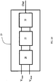
- the apparatus for treating neurological disorders 10 comprises at least one probe or electro-catheter 11 configured to be implanted in the brain of a patient to administer electrical stimulation.
- the probe or electro-catheter 11 may comprise at least three metallic contacts or leads accessible through external connections, also called electrodes 12.
- the electrodes may not be located on the same electro-catheter (e.g., an apparatus for adaptive DBS may comprise two or more electro-catheters and the electrodes may be located on two different electro-catheters).
- the apparatus for treating neurological disorders 10 may comprise one or more implantable probes where each probe may comprise one or more electrodes.
- the apparatus 10 may also comprise a connector or probe extension for each of the implantable probes.
- a probe e.g., probe 11
- the one or more electrodes are located on the distal portion and one or more connector contacts are located on the proximal portion, and one or more wires within the probe electrically connect the electrodes with the connector contacts.
- a probe 11 may comprise any number of electrodes 12, for example, 1, 2, 3, 4, 5, 6, 8, 10, 12, 16, 24, 36, 48, 64, 96, etc. and a corresponding number of connector contacts.
- a probe extension may have a distal portion having a connector block with a receptacle housing enclosing one or more conductive contacts, a proximal portion having stimulation device (e.g., apparatus 10) connector contacts, where each of the stimulation device connector contacts corresponds with a conductive contact in the receptacle housing via one or more wires, and an elongated body between the proximal portion and the distal portion.
- a probe extension may comprise any number of conductive contacts, for example, 1, 2, 3, 4, 5, 6, 8, 10, 12, 16, 24, 36, 48, 64, 96, etc. and a corresponding number of stimulation device connector contacts.
- the number of conductive contacts of the probe extension may be the same as, or greater than, the number of electrodes on the probe to which the probe extension is connected.
- the distal portion of the probe may be implantable into the target brain region, while the proximal portion of the probe may extend outside of the brain tissue and connect with a distal portion of a probe extension.
- the receptacle housing of the probe extension may be configured to retain the proximal portion of the probe such that the connector contacts of the probe electrically connect with the conductive contacts of the probe extension such that the electrodes at the distal portion of the probe are electrically coupled to the stimulation device connector contacts at the proximal portion of the probe extension.
- the stimulation device connector contacts may be configured to be coupled to a port or connector of a processing and stimulation device 14 (e.g., a header interface).
- the receptacle housing may comprise an attachment mechanism to engage or retain the proximal portion of the probe within the receptacle housing.
- the probe extension may comprise a connector sleeve or boot comprising an electrically insulating material that is disposed over at least a portion of the receptacle housing to help electrically isolate the connector contacts of the probe and the conductive contacts of the probe extension from surrounding tissue.
- the elongated body of the probe extension may have a constant diameter between the distal portion and the proximal portion, or may have a varying diameter along its length.
- the diameter of a segment of the elongated body may be larger (e.g., thicker) where that segment is intended to be located at the interface between brain tissue and the skull or skin. This may help reduce excessive twisting, torqueing, and/or bending of the wires within the elongated body of the probe extension, thereby reducing the mechanical wear on the wires and/or helping to prolong the usable life of the probe extension.
- an apparatus for treating neurological disorders 10 depicted in FIG. 1 comprises a probe 11 having four metallic contacts or electrodes 12, other variations of probes may comprise any number of electrodes (e.g., 1, 2, 3, 4, 5, 6, 7, 8, 9, 10, 12, 16, 18, 20, 25, 30, 36, 48, or more).
- an apparatus for treating neurological disorders 10 may comprise any number of probes (e.g., two or more), where each probe may have any number of electrodes.
- an apparatus for treating neurological disorders 10 may comprise a first probe with a first electrode and a second probe with a second electrode. In use, the first probe may be implanted in a first brain region and the second probe may be implanted in a second brain region (e.g., for bilateral stimulation).
- an apparatus for treating neurological disorders 10 may comprise two probes, where each probe may have four electrodes (for a total of eight channels) or may have eight electrodes (for a total of sixteen channels).
- a probe 11 may comprise multiple electrodes where a first electrode is a stimulating electrode that delivers electrical stimulation and a second electrode is a measurement electrode that acquires neural activity signals.
- a first plurality of electrodes (which may or may not be adjacent to each other) may be used for stimulating and a second plurality of electrodes (which may or may not be adjacent to each other, or may be arranged in alternating fashion with the first plurality of electrodes) may be used for acquiring neural activity signals.
- the same electrode(s) may be used for both neural activity signal acquisition and electrical stimulation simultaneously or sequentially.
- DBS probes may comprise one or more cylindrical or disc-shaped electrodes having a height from about 0.5 mm to about 3 mm, e.g., about 1.5 mm, and a diameter from about 0.5 mm to about 2 mm, e.g., about 1.27 mm.
- DBS probes may comprise two or more cylindrical electrodes (for example, 2, 4, 6, 10, 12, 15, 16, 20, etc. or more electrodes).
- DBS probes may comprise planar electrodes and/or sharp electrodes having a geometry selected at least in part based on the target neural structure or brain region.
- the spacing between two electrodes may be from about 0.25 mm to about 2 mm, e.g., about 0.5 mm, and optionally, an insulator may be disposed between two electrodes and/or around an electrode to reduce electrical coupling or cross-talk between electrodes.
- An insulator may comprise, for example, polyurethane and/or polyimide and/or the like.
- the electrodes may be made of any metal or any metallic alloy, for example, a platinum-iridium alloy.
- the electrodes 12 are connected to a processing and stimulation device 14 that comprises three functional modules connected together in a feedback and interoperating configuration: a stimulation module 16, a data acquisition module 20 and a control module 18.
- the stimulation device 14 may comprise sixteen channels, which may be connected to two probes each having eight electrodes, or four probes each having four electrodes, or eight probes each having two electrodes, etc. There may be fewer electrodes than channels, for example, although the stimulation device 14 may be configured to accommodate sixteen channels (e.g., for sixteen stimulation and/or LFP acquisition electrodes), a particular instance of an apparatus for treating neurological disorders 10 or DBS system may comprise eight electrodes (e.g., two probes each having four electrodes) or four electrodes (e.g., a single probe having four electrodes).
- the stimulation module 16 is adopted to generate a stimulation signal and to send it to the electrodes 12.
- the stimulation module 16 may comprise pulse or function generator comprising a voltage source and/or current source and circuitry configured to produce electrical pulses with certain parameter values determined by a user and/or controller, and may also comprise wires that transmit the electrical pulses to the probe, which deliver the electrical pulses to the brain region.
- the stimulation module may comprise a waveform generator (e.g., a pulse or function generator), a current controller, and a multiplexer, one or more of which may be configured to receive command signals from the control module or main processor 18.
- the command signals may comprise electrical stimulation parameter data, including, but not limited to, stimulation amplitude, pulse width, pulse frequency, duty cycle, and/or the specific probe(s) and/or electrode(s) from which electrical stimulation with the specified parameters is to be delivered.
- the current controller may be configured to set an electrical stimulation amplitude specified by the command signals, and/or the waveform generator may be configured to generate current or voltage pulses having the pulse width and/or pulse frequency specified by the command signals.
- the multiplexer may be configured to electrically connect the probes and/or electrodes specified by the command signals with the current controller and/or waveform generator.
- the multiplexer may comprise a multiplexer array that may be configured according to command signals from the main processor so that the electrical pulses from the waveform generator may be channelled to the selected probes and/or electrodes.
- the connectivity between the waveform generator and the electrodes may be arranged by the multiplexer in a monopolar stimulation configuration and/or a bipolar stimulation configuration. In a monopolar configuration, one or more electrodes may be connected to one or more active (e.g., positive) terminals of the waveform generator (with a return pad placed elsewhere on a patient).
- a first set of one or more electrodes may be connected to one or more active (e.g., positive) terminals of the waveform generator while a second set of one or more electrodes (e.g. distinct from the first set of electrodes) may be connected to one or more return (e.g., negative) terminals of the waveform generator.
- active e.g., positive
- return e.g., negative
- the stimulation module 16 may be configured to generate a stimulation signal V stim that may be characterised by a set of parameters, and to transmit the stimulation signal V stim to one or more of the electrodes 12.
- the stimulation module 16 may comprise a pulse generator having a current source (and/or voltage source) that generates electrical signals that have parameters specified by a user and/or the control module.
- a pulse generator may form output pulses having specified amplitude, frequency and/or pulse width or duration values.
- a pulse generator may generate a pulse sequence having two pulses or more pulses repeated with a duty cycle specified by a user and/or the control module 18, and the control module 18 may adjust the pulse duty cycle in accordance with one or more properties of the acquired neural activity signals (e.g., any of the patterns or properties described herein).
- the data acquisition module 20 is responsible for the acquisition of a signal representative of the cerebral activity coming from the brain of the patient, e.g. LFP signals that may represent the cerebral activity in the brain region where the probe 11 is implanted.
- the acquisition module 20 is in electrical communication with the probe 11 which may be, in some variations, the same probe used to electrically stimulate the brain region.
- the acquisition module 20 and/or the probe 11 may be configured to acquire neural activity signals, such as local-field potentials (LFPs), resulting from the activity of the brain region in proximity to the probes 11.
- the acquisition module 20 may comprise an acquisition processor and memory that stores and analyzes the acquired neural activity signals.
- the control module 18 implements an adaptive control of the stimulation module 16 based on the signal acquired by the acquisition module 20.
- the control module may have circuitry configured to facilitate communication between the acquisition module 20 and the stimulation module 16, coordinate signalling between the acquisition module 20 and the stimulation module 16, and/or to perform additional computations on the acquired neural activity signals.
- the control module 18 may be part of either the acquisition module or the stimulation module, or may be a separate module.
- the control module comprises circuitry configured to regulate/coordinate the operation of the stimulation module based on signals from the acquisition module (e.g., based on LFP signals indicative of neural activity).
- the control module may have a control module (main) processor and memory that analyzes and stores the acquired neural activity signals and/or signals from the acquisition module.
- the control module may comprise circuitry that regulates the power supplied to the stimulation module, for example, in coordination with the electrical stimulation parameters determined by the acquisition module and/or the acquired neural activity signals.
- the properties or parameters of the electrical stimulation may be determined by the acquisition module and/or the control module.
- the processors of the acquisition module and/or the control module may analyze the acquired and/or stored neural activity signals to identify variations or changes in the patterns or characteristics of neural activity signals.
- the control module may provide command signals to the pulse generator of the stimulation module to change the parameters of the electrical stimulation according to the changes in the neural activity signals detected or extracted by the acquisition module.
- the control module may also comprise a battery (e.g., a rechargeable battery), and circuitry configured to charge and/or measure the charge remaining on the battery.
- the control module may comprise a rechargeable battery, an inductive link for charging the battery and an inductive coil for facilitating the energy transfer between an external charging device and the stimulation device (which may be implanted in the patient).
- the control module may comprise wireless transmission interface (e.g., a transceiver) including an RF chip and an RF antenna for signal transmission between the implantable stimulation device and an external device.
- the acquisition module may comprise a processor that is configured to calculate the spectral power values of acquired neural activity signals, and the calculated power values may be transmitted to the control module, and the control module processor may be configured to derive stimulation parameters according to the power values and general command signals to the pulse generator to adapt or adjust the parameters of the electrical stimulation.
- the control module may comprise additional sub-modules with circuitry configured for power supply management, electrode impedance checking, and/or calibration and/or diagnostic analyses (e.g., troubleshooting) of the stimulation module.
- its main function is to measure the electric field variations of the local biopotentials directly sensing the difference between the electric potentials V 1 and V 2 referred to a common electrode 17 and to amplify such difference so as to reach a voltage level useful for the analog-to-digital conversion necessary for the signal processing.
- the acquisition module 20 may comprise input ports V 1 and V 2 that are each connected to different electrodes 12 on the probe 11 and electrical circuits that are configured to measure the electric field variations of the local biopotentials or local field potentials (LFPs) based on the signals from the input ports V 1 and V 2 .
- Electrical circuits of the acquisition module may comprise one or more processing units or processors (e.g., a CPU, and/or one or more field-programmable gate arrays, and/or one or more application-specific integrated circuits) that may be configured to perform computational operations, one or more memory elements, one or more amplifiers, one or more filters, and/or one or more analog-to-digital converters.
- the acquisition module 20 may measure electric field variations by sensing changes in the electric potentials V 1 and V 2 (e.g., difference(s) between V 1 and V 2 , or values of V 1 or V 2 as referenced to a common or ground electrode 17) using a pre-amplifier and may amplify the changes (and/or any electric field variations) using an amplifier.
- the amplified output may be converted to a digital signal using an analog-to-digital converter, and the digital signal may be transmitted to the control module 18 (shown in FIG. 1 ) for further analysis and processing.
- the acquisition module 20 may comprise an acquisition processor that is configured to transform the acquired neural activity signals (e.g., LFPs) into spectral signals (e.g., spectral power values) that represent cerebral activity in the frequency domain (i.e., frequency-domain representation).
- an acquisition processor of the acquisition module may be configured to carry out a Fourier Transform (e.g., a Fast-Fourier Transform or a Discrete-Fourier Transform) of the neural activity signals from input ports V 1 and V 2 .
- the acquisition processor may comprise a general-purpose microprocessor that executes instructions from a software program to perform the frequency-domain signal transformation.
- the acquisition processor may comprise a digital signal processor (DSP) that has specialized electrical circuitry for performing the frequency-domain signal transformation.
- the acquisition processor may comprise an FPGA and/or ASIC configured for performing the frequency-domain signal transformation.
- the acquisition processor(s) of the acquisition module 20 may be configured to calculate the power values of the neural activity signals in certain frequency bands of interest (e.g., the low-frequency band, alpha frequency band, beta frequency band, gamma frequency band, and/or any range of frequencies as may be desirable).
- the acquisition processor may perform the power calculation in the time domain.
- the acquisition processor may comprise a band pass filter followed by a rectifier to perform the power calculation in the time domain.
- the processor(s) of the acquisition module 20 may comprise an integral block and a derivative block (not illustrated) of the power values in order to highlight respectively slow and fast time changes of the power values.
- An integral or integration block may be configured to combine power values over time (e.g., by calculating an average value, which may be a moving average value) to help enhance slower changes or longer-term trends in power values.
- a derivative block may be configured to combine power values to help enhance faster or instantaneous changes in power values.
- the acquisition module 20 comprises a front-end block 27 (shown in FIG. 2c ) and an A/D converter block 23.
- the A/D converter block 23 may comprise a delta-sigma converter.
- the front-end block 27 may comprise a pre-filter stage 21 and a suppression filter stage 22.
- the pre-filter stage 21, the suppression filter stage 22 and the A/D converter block 23 may comprise one or more fully-differential switched-capacitor circuits.
- the pre-filter stage 21 may comprise a fully-differential switched-capacitor architecture which may be configured for both amplification and antialiasing filtering.
- the suppression filter stage 22 may comprise a fully-differential switched-capacitor architecture which provides for low-pass filtering and additional amplification.
- the A/D converter block 23 may comprise a switched-capacitor network which provides for amplification and analog-to-digital signal conversion.
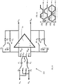
- the pre-filter stage 21 may be configured to differentially amplify the signal to a value greater than the input referred noise of the suppression filter stage 22 without compromising the minimum detectable signal (in the order of ⁇ V) and by avoiding the saturation of the recording chain. Accordingly, as schematically depicted in FIG. 3 , the pre-filter stage 21 may comprise a fully-differential operational amplifier 21a, a plurality of input capacitors C 1 ,C 2 connected at its input terminals and feedback capacitors C 3 ,C 4 connected between its input and output terminals. The gain of the pre-filter stage 21 is configured by choosing the values of the input and the feedback capacitors. Variations of pre-filter stage circuitry are further described below.
- the pre-filter stage 21 and/or suppression filter stage 22 may comprise a ladder configuration of the fully-differential low-pass switched capacitor filters.
- the ladder configuration makes use of basic building units, such as those depicted in FIG. 3 .
- the basic building unit is a first-order bilinear switched capacitor integrator which allows an improvement of the CMRR at the frequencies of interest as compared to the CMRR of conventional integrators ( FIG. 4 ).
- FIG. 5 the basic building unit of FIG. 3 achieves higher CMMR compared to the conventional integrator of FIG. 4 .
- the input network 21b of the used integrator ( FIG. 3 ) adopts a parasitic insensitive switched capacitor configuration being each node of the switched capacitor connected between two voltage sources V 1a , V 2a , or between a common reference voltage V ref and virtual ground.
- the inputs V 1a and V 2a are alternatively connected to one end of two input capacitors C 1 and C 2 .
- the other end of the two input capacitors C 1 ,C 2 is alternatively connected to a reference voltage V ref or, each respectively, to one of two inputs of the fully-differential operational amplifier 21a.
- Each input of the operational amplifier 21a is connected to one respective differential output through interposition of a first C 3 and a second C 4 feedback capacitor, respectively; in this configuration, by setting the common mode of the inputs V 1a and V 2a equal to V ref , the inputs V + and V - of the amplifier 21a are also polarized at this value for the whole sampling period.
- V 1 b ⁇ V 1 a z ⁇ 1 C 1 + V 2 a C 1 ⁇ 1 C 3
- V 2 b ⁇ V 2 a z ⁇ 1 C 2 + V 1 a C 2 ⁇ 1 C 4
- z is the discrete-time variable used in signal-processing mathematics.
- V O ⁇ C 1 C 2 + C 2 C 4 V 1 a ⁇ V 2 a
- the basic building unit is a first-order bilinear switched capacitor integrator configured to implement correlated double sampling (CDS).
- CDS correlated double sampling
- each input of the operational amplifier 21a is connected to one respective differential output through interposition of a first pair of feedback capacitors C 3 and C 5 and a second pair of feedback capacitors C 4 and C 6 , respectively. More in detail, a third C 5 and a fourth C 6 feedback capacitor are connected in parallel to the first C 3 and second C 4 feedback capacitor, respectively.
- the feedback capacitor pairs C 3 ,C 5 and C 4 ,C 6, are alternatively connected or disconnected to the respective input of the amplifier 21a.
- the timing of the connections between the inputs V 1a , V 2a , and the input capacitors C 1 ,C 2 , the input capacitors C 1 ,C 2, and the inputs of the amplifier V 1a' , V 2a' , the pairs of feedback capacitors C 3 ,C 5 and C 4 ,C 6 and the inputs of the amplifier V 1a' , V 2a' , is controlled by a plurality of clock signals as shown in FIG. 6a (i.e., four clock signals Clk1, Clk2, Clk3, Clk4).
- the switch connectivity state i.e., circuit nodes that are connected by the switch) during the high state of a particular clock signal is indicated by ⁇ 1 , ⁇ 2 , ⁇ 1a , ⁇ 2a .
- Each clock signal of the plurality of clock signals Clk1, Clk2, Clk3, Clk4 has a phase shift with respect to the others.
- Clock signals Clk1, Clk2 control the connection between the inputs V 1a , V 2a and the input capacitors C 1 ,C 2, and the connection between the pairs of feedback capacitors C 3 ,C 5 and C 4 ,C 6 and the inputs of the amplifier V 1a' , V 2a' with a 180° phase-shift.
- FIG. 6 indicates the connectivity for each circuit switch node, each node labelled according to the clock phases ⁇ 1 , ⁇ 2 , ⁇ 1a , ⁇ 2a of each corresponding clock signals Clk1, Clk2, Clk3, Clk4.
- the pre-filter stage 21 is, preferably, implemented as a third order fully-differential switched capacitor low-pass filter, e.g. using the building units of FIG. 6 . More preferably, the pre-filter stage 21 is implemented as third order Cauer (e.g., elliptic) filter with a sampling rates of 256 kHz, a -3 dB bandwidth of 3 kHz.
- third order Cauer e.g., elliptic
- the pre-filter stage 21 provides amplification while filtering out high-frequency components that can cause aliasing effects (antialiasing pre-filter).
- the suppression filter stage 22 performs a suppression of the artifacts by cutting off frequencies above the interested frequency band (2-40 Hz). It is, preferably, implemented as a seventh order fully-differential switched capacitor low-pass filter. More preferably, the suppression filter stage 22 is implemented as elliptic ladder filter operating at 32 kHz and with a cut-off frequency of 40 Hz. Its transfer function is characterized by an attenuation of -52dB at 130 Hz.
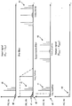
- FIGS. 8a-8d are graphs conceptually illustrating the frequency components of a signal at various stages within the front-end block 27.
- FIG. 8a illustrates the frequency components of input signal (V 1a -V 2a ) which comprises both the neural signal 40 located at baseband and the harmonics of the stimulus artifact 41.
- FIG. 8b illustrates the frequency components of input signal 40,41 sampled at the first clock frequency F clock_PreFilter of the pre-filter stage 21.
- the frequency components of the sampled input signal 42 (generated through sampling at the first clock frequency F clock_PreFilter ) are represented at the first clock frequency F clock_PreFilter only.
- the frequency components of the 1/f noise 43 are represented superimposed to the neural component 40 of the original input signal at the baseband frequency.
- Figure 8b also shows the first cut-off frequency F cut_PreFilter of the pre-filter stage 21.
- the frequency components of the 1/f noise 43 are removed by the pre-filter stage 21 through correlated double sampling, namely through double sampling of the signal such that the second sample - which is the one bearing noise related to itself for stationary reasons - is subtracted from the first sample. In terms of frequency response, this results in a high pass filtering (not represented) that only acts on the 1/f noise 43 but not on the input signal 42.
- FIG. 8c illustrates the frequency components downstream from the pre-filter stage 21 (intermediate signal) and sampled at the second clock frequency F clock_SuppFilter of the suppression filter stage 22.
- the frequency components of the sampled intermediate signal 44 (generated through sampling at the second clock frequency F clock_SuppFilter ) are represented at the second clock frequency F clock_SuppFilter only and the second cut-off frequency F cut_SuppFilter of the suppression filter stage 22 is also shown. From FIG.
- the pre-filter 21 attenuates the frequency components of the sampled input signal 42 repeated every multiple of the sample frequency that were located outside of the passband (0 Hz - F cut_PreFilter ) of the pre-filter 21 shown in FIG. 8b .
- FIG. 8d is a graph that illustrates the frequency components of the output signal (V 1out -V 2out ) ideally comprising only the neural signal component 40.
- FIG. 8d shows that the suppression filter 22 attenuates the frequency components from the stimulus artifact 41 and the frequency component of the modulated intermediate signal 44 located outside of the passband (0 Hz - F cut_SuppFilter ) of the suppression filter 22 shown in FIG. 8c .
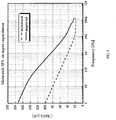
- FIG. 9a and FIG. 9b show the effect of the acquisition module 20, namely provided with a multi-stage fully-differential switched capacitor integrated front-end block 21 configured for discrete-time signal processing ( FIG. 9b ), compared to a prior art single-ended analogue front-end ( FIG. 9a ).
- FIG. 9b shows the effect of the acquisition module 20, namely provided with a multi-stage fully-differential switched capacitor integrated front-end block 21 configured for discrete-time signal processing
- FIG. 9a shows the effect of the acquisition module 20, namely provided with a multi-stage fully-differential switched capacitor integrated front-end block 21 configured for discrete-time signal processing ( FIG. 9b ), compared to a prior art single-ended analogue front-end ( FIG. 9a ).
- the broadband spectral content of the stimulus artifact is theoretically infinite. For any finite sampling rate, this turns into unavoidable aliasing effects which could be reduced by increasing the sampling frequency. However, this would negatively affect the power consumption, which is not acceptable for wearable and/or implantable devices.
- a first sampling stage 28 with high sampling rate (preferably at least of 32 kHz) is followed by a filter stage 29 for removing the quantization noise and a decimation stage 30, as shown in FIG. 2d .
- the sampling stage 28 comprises a single-bit, third-order, discrete-time delta-sigma (DT- ⁇ ) modulator.
- the filter stage 29, being a low-pass filter, is designed to further suppress the residual stimulation interferences, by setting the cut-off frequency at a value smaller than the stimulation frequency.
- the first sampling stage 28 of the A/D converter block 23 includes an amplification sub-stage (not illustrated) before the analog-to-digital conversion to adjust the dynamic range of the signal.
- the A/D converter block 23 has a differential signal as input and provides a digital data at the output.
- the acquisition module 20 may optionally comprise an input switch module, a low-pass filter module, and a high-pass filter module 24, 25, 26.
- the input switch module 24 may be in communication with the stimulation module 16.
- the stimulation module 16 may generate and transmit a synchronization signal 24a to the input switch module 24, which may indicate whether to connect the input V 1a and V 2a to a reference voltage 17 or to leave them disconnected from the recording system during the stimulation.
- This module 24 provides for a synchronization with the stimulation module 16 or uses the electric stimulus itself in order to be able to disconnect the inputs of the front-end block 27 during stimulus. Disconnecting or grounding the inputs during each stimulus and re-connecting them to the recording system after each stimulation pulse provides for an additional suppression/mitigation of the stimulus artifact, thus unburdening the attenuation requirements at the level of the second suppression filter stage 22.
- the opening and closing of the Input Switch module 24 may introduce fluctuations characterized by high frequency frequencies which are removed or mitigated using a second functional module 25 which implements a low-pass filter.
- a third functional module 26 provides for high-pass filtering so as to eliminate the DC common mode voltages (before the Input Switch 24) and the DC differential components produced at the interface of the electrode and the brain.
- the apparatuses and methods described herein provide a solution for implantable neurostimulator devices requiring for ultra-low power features while being constrained by circuit dimensions.
- a multi-stage (e.g. two stage) front end block using fully-differential switched capacitor integrators configured for discrete-time signal processing represent a unique solution to record neural signals - namely signal characterized by low amplitudes ( ⁇ 1 ⁇ V) at very low frequencies (1-40 Hz) - in presence of the stimulus artifact (usually having an amplitude of tens of mV).
- switching capacitors circuits allow for low power and low size implementation.
Landscapes
- Health & Medical Sciences (AREA)
- Life Sciences & Earth Sciences (AREA)
- Engineering & Computer Science (AREA)
- General Health & Medical Sciences (AREA)
- Veterinary Medicine (AREA)
- Biomedical Technology (AREA)
- Public Health (AREA)
- Animal Behavior & Ethology (AREA)
- Neurology (AREA)
- Neurosurgery (AREA)
- Nuclear Medicine, Radiotherapy & Molecular Imaging (AREA)
- Radiology & Medical Imaging (AREA)
- Biophysics (AREA)
- Heart & Thoracic Surgery (AREA)
- Pathology (AREA)
- Surgery (AREA)
- Molecular Biology (AREA)
- Medical Informatics (AREA)
- Physics & Mathematics (AREA)
- Psychology (AREA)
- Physiology (AREA)
- Hospice & Palliative Care (AREA)
- Psychiatry (AREA)
- Cardiology (AREA)
- Computer Networks & Wireless Communication (AREA)
- Electrotherapy Devices (AREA)
- Measurement And Recording Of Electrical Phenomena And Electrical Characteristics Of The Living Body (AREA)
Claims (11)
- Appareil (10) de traitement de troubles neurologiques comprenant :- au moins une électrode (12) apte à être implantée dans le cerveau d'un patient, et- un dispositif de stimulation et de traitement (14) connecté à l'au moins une électrode (12), dans lequel le dispositif de stimulation et de traitement (14) comprend au moins- un module de stimulation (16) configuré pour générer un signal de stimulation à envoyer à l'au moins une électrode (12), et- un module d'acquisition (20) configuré pour acquérir un signal neuronal mesuré par l'au moins une électrode (12) en provenance du cerveau du patient,
dans lequel le module d'acquisition (20) comprend au moins un bloc frontal (27) configuré pour amplifier la différence de potentiel de ses signaux d'entrée (V1a, V2a) et pour filtrer un artefact de stimulation par coupure de fréquences au-dessus d'une bande de fréquences prédéfinie ; caractérisé par le fait que le bloc frontal (27) comprend un circuit à condensateurs commutés entièrement différentiel multi-étage configuré pour un traitement de signal en temps discret. - Appareil (10) de traitement de troubles neurologiques selon la revendication 1, dans lequel le bloc frontal (27) comprend un étage de préfiltre (21) et un étage de filtre de suppression (22) positionné en aval de l'étage de préfiltre (21), chacun de l'étage de préfiltre (21) et de l'étage de filtre de suppression (22) comprenant un circuit à condensateurs commutés entièrement différentiel configuré pour un traitement de signal en temps discret.
- Appareil (10) de traitement de troubles neurologiques selon la revendication 2, dans lequel l'étage de préfiltre (21) comprend un premier filtre à condensateurs commutés passe-bas entièrement différentiel, synchronisé à une première fréquence d'horloge, le premier filtre à condensateurs commutés entièrement différentiel comprenant au moins un intégrateur à condensateurs commutés bilinéaire.
- Appareil (10) de traitement de troubles neurologiques selon la revendication 2 ou 3, dans lequel l'étage de filtre de suppression (22) comprend un second filtre à condensateurs commutés passe-bas entièrement différentiel, synchronisé à une seconde fréquence d'horloge, le second filtre à condensateurs commutés entièrement différentiel comprenant de préférence au moins un intégrateur à condensateurs commutés bilinéaire.
- Appareil (10) de traitement de troubles neurologiques selon la revendication 3 ou 4, dans lequel l'intégrateur à condensateurs commutés bilinéaire est configuré pour mettre en œuvre un échantillonnage double corrélé.
- Appareil (10) de traitement de troubles neurologiques selon l'une quelconque des revendications 3 à 5, dans lequel l'intégrateur à condensateurs commutés bilinéaire comprend deux entrées (V1a, V2a) qui sont aptes à être connectées de manière alternée à une extrémité de deux condensateurs d'entrée (C1, C2), l'autre extrémité des deux condensateurs d'entrée (C1, C2) étant configurée pour se connecter de manière alternée à une source de tension de référence (Vref) ou, chacune respectivement, à l'une de deux entrées d'un amplificateur opérationnel (21a), chaque entrée de l'amplificateur opérationnel (21a) étant apte à être connectée à une sortie respective de l'amplificateur opérationnel (21c) par l'intermédiaire de l'interposition d'une première (C3, C5) et d'une seconde (C4, C6) paire de condensateurs de rétroaction, respectivement, dans lequel les paires de condensateurs de rétroaction (C3, C5) et (C4, C6) comprennent chacune un premier (C3, C4) et un second (C5, C6) condensateur de rétroaction connectés en parallèle, et sont configurées pour se connecter de manière alternée à l'entrée respective de l'amplificateur (21a).
- Appareil (10) de traitement de troubles neurologiques selon la revendication 3 ou 4, dans lequel l'intégrateur à condensateurs commutés bilinéaire comprend deux entrées (V1a, V2a) qui sont aptes à être connectées de manière alternée à une extrémité de deux condensateurs d'entrée (C1, C2), l'autre extrémité des deux condensateurs d'entrée (C1, C2) étant configurée pour se connecter de alternée à une source de tension de référence (Vref) ou, chacune respectivement, à l'une de deux entrées d'un amplificateur opérationnel (21a), chaque entrée de l'amplificateur opérationnel (21a) étant apte à être connectée à une sortie respective de l'amplificateur opérationnel (21c) par l'intermédiaire de l'interposition d'un premier (C3) et d'un second (C4) condensateur de rétroaction, respectivement.
- Appareil (10) de traitement de troubles neurologiques selon l'une quelconque des revendications 2 à 7, dans lequel le circuit à condensateurs commutés entièrement différentiel de l'étage de préfiltre et/ou de l'étage de filtre de suppression (22) est mis en œuvre en tant que filtre en échelle comprenant une pluralité d'intégrateurs à condensateurs commutés dans une émulation active de structure d'échelle LC sans perte.
- Appareil (10) de traitement de troubles neurologiques selon l'une quelconque des revendications 4 à 8, comprenant au moins l'un entre :- dans lequel le premier filtre à condensateurs commutés entièrement différentiel de l'étage de préfiltre (21) présente un ordre inférieur à un ordre du second filtre à condensateurs commutés entièrement différentiel de l'étage de filtre de suppression (22) ;- dans lequel la première fréquence d'horloge du premier filtre à condensateurs commutés entièrement différentiel de l'étage de préfiltre (21) est supérieure à la seconde fréquence d'horloge du second filtre à condensateurs commutés entièrement différentiel de l'étage de filtre de suppression (22) ;- dans lequel la première fréquence d'horloge est d'au moins 1 KHz ;- dans lequel une première fréquence de coupure du premier filtre à condensateurs commutés entièrement différentiel de l'étage de préfiltre (21) est supérieure à une seconde fréquence de coupure du second filtre à condensateurs commutés entièrement différentiel de l'étage de filtre de suppression (22) ;- dans lequel une première fréquence de coupure du premier filtre à condensateurs commutés entièrement différentiel de l'étage de préfiltre (21) est d'au moins 50 Hz et est inférieure à la seconde fréquence d'horloge ; et- dans lequel une seconde fréquence de coupure du second filtre à condensateurs commutés entièrement différentiel de l'étage de filtre de suppression (22) est dans la plage d'environ 35-250 Hz.
- Appareil (10) de traitement de troubles neurologiques selon l'une quelconque des revendications précédentes, dans lequel le module d'acquisition (20) comprend en outre un bloc convertisseur analogique/numérique, A/N, (23) connecté en aval du bloc frontal (27), et dans lequel le bloc convertisseur A/N comprend de manière facultative un convertisseur delta-sigma et/ou un circuit à condensateurs commutés entièrement différentiel.
- Appareil (10) de traitement de troubles neurologiques selon la revendication 10, dans lequel le bloc convertisseur A/N (23) comprend un premier étage d'échantillonnage (28), suivi d'un étage de filtre (29) configuré pour éliminer le bruit de quantification et d'un étage de décimation (30).
Applications Claiming Priority (2)
| Application Number | Priority Date | Filing Date | Title |
|---|---|---|---|
| IT201800002962A IT201800002962A1 (it) | 2018-02-22 | 2018-02-22 | Apparato per il trattamento di disordini neurologici mediante elettrostimolazione e metodo di elaborazione del segnale neurologico raccolto da detto apparato |
| PCT/IB2019/051428 WO2019162878A1 (fr) | 2018-02-22 | 2019-02-21 | Appareil de traitement de troubles neurologiques par électrostimulation et méthode de traitement de signaux neuronaux collectés par ledit appareil |
Publications (2)
| Publication Number | Publication Date |
|---|---|
| EP3554628A1 EP3554628A1 (fr) | 2019-10-23 |
| EP3554628B1 true EP3554628B1 (fr) | 2020-07-15 |
Family
ID=62089986
Family Applications (1)
| Application Number | Title | Priority Date | Filing Date |
|---|---|---|---|
| EP19710161.1A Active EP3554628B1 (fr) | 2018-02-22 | 2019-02-21 | Appareil de traitement de troubles neurologiques par électrostimulation |
Country Status (9)
| Country | Link |
|---|---|
| US (4) | US10933243B2 (fr) |
| EP (1) | EP3554628B1 (fr) |
| JP (1) | JP7232268B2 (fr) |
| CN (1) | CN111712295B (fr) |
| AU (1) | AU2019224826B2 (fr) |
| CA (1) | CA3092001A1 (fr) |
| IL (1) | IL276604B (fr) |
| IT (1) | IT201800002962A1 (fr) |
| WO (1) | WO2019162878A1 (fr) |
Families Citing this family (17)
| Publication number | Priority date | Publication date | Assignee | Title |
|---|---|---|---|---|
| US10596379B2 (en) | 2015-02-16 | 2020-03-24 | Newronika S.r.l. | Apparatus and method for treating neurological disorders |
| IT201800002962A1 (it) | 2018-02-22 | 2019-08-22 | Newronika Srl | Apparato per il trattamento di disordini neurologici mediante elettrostimolazione e metodo di elaborazione del segnale neurologico raccolto da detto apparato |
| US11318309B2 (en) | 2018-12-13 | 2022-05-03 | Newronika S.P.A. | Method and apparatus for treating Tourette Syndrome by brain stimulation |
| EP3839833A1 (fr) * | 2019-12-16 | 2021-06-23 | ams International AG | Amplificateur neuronal, réseau neuronal et dispositif de capteur |
| US12569685B2 (en) | 2020-04-20 | 2026-03-10 | University Of Florida Research Foundation, Inc. | Simultaneous bilateral stimulation using neurostimulator |
| CN116157178A (zh) | 2020-07-17 | 2023-05-23 | 纽罗尼卡公司 | 用于自适应深部脑刺激的系统和方法 |
| CN112402793A (zh) * | 2020-11-13 | 2021-02-26 | 杭州神络医疗科技有限公司 | 一种骶神经刺激装置 |
| CN112773334A (zh) * | 2021-02-05 | 2021-05-11 | 杭州诺为医疗技术有限公司 | 一种植入式闭环系统中生物电信号处理方法和装置 |
| CN113058155B (zh) * | 2021-03-19 | 2024-09-03 | 中国科学院空天信息创新研究院 | 电引导治疗装置及方法 |
| JP2022148473A (ja) * | 2021-03-24 | 2022-10-06 | 株式会社ミツトヨ | フロントエンド回路及びエンコーダ |
| CN113208616A (zh) * | 2021-04-15 | 2021-08-06 | 北京脑陆科技有限公司 | 对脑电信号进行处理的设备 |
| US11147982B1 (en) | 2021-05-05 | 2021-10-19 | Kambix Innovations, Llc | Method and system for thermal stimulation of targeted neural circuits for neurodegenerative disorders |
| CN113940689B (zh) * | 2021-09-14 | 2023-05-05 | 复旦大学 | 一种闭环深部脑刺激伪迹抑制系统 |
| US20240139551A1 (en) * | 2022-10-28 | 2024-05-02 | Alien Sandbox, LLC | Transducer Probe for Direct Ultrasonic Neuromodulation and Measurement |
| CN115400350B (zh) * | 2022-11-01 | 2023-06-16 | 北京金博智慧健康科技有限公司 | 一种神经调控装置及其波形调控方法 |
| WO2025045094A1 (fr) * | 2023-08-30 | 2025-03-06 | 景昱医疗科技(苏州)股份有限公司 | Fil d'électrode, système de stimulateur et support de stockage lisible par ordinateur |
| CN119537286B (zh) * | 2024-10-17 | 2026-03-31 | 清华大学 | 用于神经信号接收的接口电路和系统 |
Family Cites Families (103)
| Publication number | Priority date | Publication date | Assignee | Title |
|---|---|---|---|---|
| US6480743B1 (en) | 2000-04-05 | 2002-11-12 | Neuropace, Inc. | System and method for adaptive brain stimulation |
| US20020169485A1 (en) | 1995-10-16 | 2002-11-14 | Neuropace, Inc. | Differential neurostimulation therapy driven by physiological context |
| US5683422A (en) | 1996-04-25 | 1997-11-04 | Medtronic, Inc. | Method and apparatus for treating neurodegenerative disorders by electrical brain stimulation |
| US6016449A (en) | 1997-10-27 | 2000-01-18 | Neuropace, Inc. | System for treatment of neurological disorders |
| US7231254B2 (en) | 1998-08-05 | 2007-06-12 | Bioneuronics Corporation | Closed-loop feedback-driven neuromodulation |
| US9113801B2 (en) | 1998-08-05 | 2015-08-25 | Cyberonics, Inc. | Methods and systems for continuous EEG monitoring |
| US6366813B1 (en) | 1998-08-05 | 2002-04-02 | Dilorenzo Daniel J. | Apparatus and method for closed-loop intracranical stimulation for optimal control of neurological disease |
| US7277758B2 (en) | 1998-08-05 | 2007-10-02 | Neurovista Corporation | Methods and systems for predicting future symptomatology in a patient suffering from a neurological or psychiatric disorder |
| US6820019B1 (en) | 1999-07-31 | 2004-11-16 | Medtronic, Inc. | Device and method for determining and communicating the remaining life of a battery in an implantable neurological tissue stimulating device |
| US6560486B1 (en) | 1999-10-12 | 2003-05-06 | Ivan Osorio | Bi-directional cerebral interface system |
| JP2003516206A (ja) | 1999-12-07 | 2003-05-13 | クラスノウ インスティテュート | 神経系の適応性電場調整 |
| US6873872B2 (en) | 1999-12-07 | 2005-03-29 | George Mason University | Adaptive electric field modulation of neural systems |
| US6473639B1 (en) | 2000-03-02 | 2002-10-29 | Neuropace, Inc. | Neurological event detection procedure using processed display channel based algorithms and devices incorporating these procedures |
| US7024247B2 (en) | 2001-10-15 | 2006-04-04 | Northstar Neuroscience, Inc. | Systems and methods for reducing the likelihood of inducing collateral neural activity during neural stimulation threshold test procedures |
| US7089059B1 (en) | 2000-11-03 | 2006-08-08 | Pless Benjamin D | Predicting susceptibility to neurological dysfunction based on measured neural electrophysiology |
| US7787958B2 (en) | 2001-04-13 | 2010-08-31 | Greatbatch Ltd. | RFID detection and identification system for implantable medical lead systems |
| US7127296B2 (en) | 2001-11-02 | 2006-10-24 | Advanced Bionics Corporation | Method for increasing the therapeutic ratio/usage range in a neurostimulator |
| US7853330B2 (en) | 2001-12-04 | 2010-12-14 | Boston Scientific Neuromodulation Corporation | Apparatus and method for determining the relative position and orientation of neurostimulation leads |
| US6993384B2 (en) | 2001-12-04 | 2006-01-31 | Advanced Bionics Corporation | Apparatus and method for determining the relative position and orientation of neurostimulation leads |
| US7110820B2 (en) | 2002-02-05 | 2006-09-19 | Tcheng Thomas K | Responsive electrical stimulation for movement disorders |
| US7236830B2 (en) | 2002-12-10 | 2007-06-26 | Northstar Neuroscience, Inc. | Systems and methods for enhancing or optimizing neural stimulation therapy for treating symptoms of Parkinson's disease and/or other movement disorders |
| US7582062B2 (en) | 2003-09-12 | 2009-09-01 | Medical Research Council | Methods of neural centre location and electrode placement in the central nervous system |
| US8396565B2 (en) | 2003-09-15 | 2013-03-12 | Medtronic, Inc. | Automatic therapy adjustments |
| US20050228306A1 (en) * | 2004-03-29 | 2005-10-13 | Vivosonic Inc. | System and method for filtering and detecting faint signals in noise |
| US8135473B2 (en) | 2004-04-14 | 2012-03-13 | Medtronic, Inc. | Collecting posture and activity information to evaluate therapy |
| US8187209B1 (en) | 2005-03-17 | 2012-05-29 | Great Lakes Neurotechnologies Inc | Movement disorder monitoring system and method |
| US8131357B2 (en) | 2005-04-01 | 2012-03-06 | Boston Scientific Neuromodulation Corporation | Apparatus and methods for detecting migration of neurostimulation leads |
| WO2006119015A1 (fr) | 2005-04-30 | 2006-11-09 | Medtronic, Inc. | Ajustement de stimulation sur la base d'une impedance |
| ITMI20052061A1 (it) * | 2005-10-28 | 2007-04-29 | Fondazione Irccs | Apparecchiatura per il trattamento di disturbi neurologici mediante stimolazione cerebrale cronica adattativa retroazionata da biopotenziali locali |
| EP1998849B1 (fr) | 2006-03-24 | 2014-12-24 | Medtronic, Inc. | Collecte d'informations de démarche destinée à l'évaluation et au contrôle d'une thérapie |
| US8190251B2 (en) | 2006-03-24 | 2012-05-29 | Medtronic, Inc. | Method and apparatus for the treatment of movement disorders |
| US20080004660A1 (en) | 2006-06-28 | 2008-01-03 | Medtrode Inc. | Systems and methods for improving a cognitive function |
| US8644930B2 (en) | 2006-08-28 | 2014-02-04 | Medtronic, Inc. | Operational electrode impedance measurement for an implantable medical stimulator |
| US8280514B2 (en) | 2006-10-31 | 2012-10-02 | Advanced Neuromodulation Systems, Inc. | Identifying areas of the brain by examining the neuronal signals |
| US7385443B1 (en) | 2007-01-31 | 2008-06-10 | Medtronic, Inc. | Chopper-stabilized instrumentation amplifier |
| US7391257B1 (en) * | 2007-01-31 | 2008-06-24 | Medtronic, Inc. | Chopper-stabilized instrumentation amplifier for impedance measurement |
| US20080183245A1 (en) | 2007-01-31 | 2008-07-31 | Van Oort Geeske | Telemetry of external physiological sensor data and implantable medical device data to a central processing system |
| US9615744B2 (en) * | 2007-01-31 | 2017-04-11 | Medtronic, Inc. | Chopper-stabilized instrumentation amplifier for impedance measurement |
| US8036736B2 (en) | 2007-03-21 | 2011-10-11 | Neuro Vista Corporation | Implantable systems and methods for identifying a contra-ictal condition in a subject |
| EP3088045B1 (fr) | 2007-07-20 | 2019-06-19 | Boston Scientific Neuromodulation Corporation | Utilisation d'une forme d'impulsion de stimulation pour réguler un ordre de recrutement neuronal et un effet clinique |
| US8019419B1 (en) | 2007-09-25 | 2011-09-13 | Dorin Panescu | Methods and apparatus for leadless, battery-less, wireless stimulation of tissue |
| WO2009051638A1 (fr) | 2007-10-16 | 2009-04-23 | Medtronic, Inc. | Commande de thérapie selon un état de mouvement de patient |
| US9248280B2 (en) | 2007-11-02 | 2016-02-02 | Boston Scientific Neuromodulation Corporation | Closed-loop feedback for steering stimulation energy within tissue |
| US9662502B2 (en) | 2008-10-14 | 2017-05-30 | Great Lakes Neurotechnologies Inc. | Method and system for tuning of movement disorder therapy devices |
| WO2010048613A2 (fr) | 2008-10-24 | 2010-04-29 | The General Hospital Corporation | Système et procédé de stimulation configurable de manière dynamique permettant de simuler en profondeur le cerveau |
| WO2010051382A1 (fr) | 2008-10-31 | 2010-05-06 | Medtronic, Inc. | Surveillance du circuit de l'humeur en vue de la régulation de l'administration d'un traitement |
| EP2411090B1 (fr) | 2009-03-22 | 2015-08-19 | Sorin CRM SAS | Thérapie de stimulation cérébrale profonde optimale avec apprentissage q |
| US8504154B2 (en) | 2009-03-30 | 2013-08-06 | Medtronic, Inc. | Physiological signal amplifier with voltage protection and fast signal recovery |
| US9399132B2 (en) | 2009-06-30 | 2016-07-26 | Boston Scientific Neuromodulation Corporation | Method and device for acquiring physiological data during tissue stimulation procedure |
| US9399144B2 (en) | 2009-09-10 | 2016-07-26 | Newton Howard | System, method, and applications of using the fundamental code unit and brain language |
| US9814885B2 (en) | 2010-04-27 | 2017-11-14 | Medtronic, Inc. | Stimulation electrode selection |
| US9789302B2 (en) * | 2010-09-01 | 2017-10-17 | Medtronic, Inc. | Symmetrical physiological signal sensing with a medical device |
| US8473063B2 (en) | 2010-09-22 | 2013-06-25 | Medtronic, Inc. | Method and apparatus for event-triggered reinforcement of a favorable brain state |
| US8433419B2 (en) | 2010-10-13 | 2013-04-30 | Cardiac Pacemakers, Inc. | Method and apparatus for controlling neurostimulation according to physical state |
| US9061140B2 (en) | 2010-10-13 | 2015-06-23 | Boston Scientific Neuromodulation Corporation | Sample and hold circuitry for monitoring voltages in an implantable neurostimulator |
| US9144686B2 (en) | 2011-01-21 | 2015-09-29 | Neurocardiac Innovations, Llc | Implantable medical device with external access for recharging and data communication |
| DK3357533T3 (da) | 2011-05-13 | 2021-11-15 | Saluda Medical Pty Ltd | Apparat til kontrol af en neural stimulus |
| WO2012158834A1 (fr) | 2011-05-16 | 2012-11-22 | Second Sight Medical Products, Inc. | Interface corticale pourvue d'une rangée d'électrodes divisée en doigts séparés et/ou d'un émetteur-récepteur sans fil |
| US9888861B2 (en) * | 2011-08-25 | 2018-02-13 | Medtronic, Inc. | Method and apparatus for detecting a biomarker in the presence of electrical stimulation |
| US8543221B2 (en) | 2011-09-22 | 2013-09-24 | Advanced Neuromodulation Systems, Inc. | External systems for detecting implantable neurostimulation leads and devices, and methods of using same |
| WO2013123112A1 (fr) | 2012-02-19 | 2013-08-22 | Medtronic, Inc. | Détermination d'un profil de réponse à une stimulation du cerveau |
| US8892208B2 (en) | 2012-06-13 | 2014-11-18 | The Regents Of The University Of Michigan | Closed-loop neural stimulation |
| US9375582B2 (en) | 2012-08-31 | 2016-06-28 | Nuvectra Corporation | Touch screen safety controls for clinician programmer |
| US9211417B2 (en) | 2012-09-10 | 2015-12-15 | Great Lakes Neurotechnologies Inc | Movement disorder therapy system, devices and methods, and intelligent methods of tuning |
| US9238142B2 (en) | 2012-09-10 | 2016-01-19 | Great Lakes Neurotechnologies Inc. | Movement disorder therapy system and methods of tuning remotely, intelligently and/or automatically |
| US9656089B2 (en) | 2012-12-14 | 2017-05-23 | Boston Scientific Neuromodulation Corporation | Method for automation of therapy-based programming in a tissue stimulator user interface |
| US9592383B2 (en) | 2013-01-23 | 2017-03-14 | Cornell University | System and methods for multi-site activation of the thalamus |
| US9119964B2 (en) | 2013-03-06 | 2015-09-01 | Boston Scientific Neuromodulation Corporation | System for deep brain stimulation employing a sensor for monitoring patient movement and providing closed loop control |
| US9521979B2 (en) | 2013-03-15 | 2016-12-20 | Medtronic, Inc. | Control of spectral agressors in a physiological signal monitoring device |
| US11083402B2 (en) | 2013-06-04 | 2021-08-10 | Medtronic, Inc. | Patient state determination based on one or more spectral characteristics of a bioelectrical brain signal |
| EP3035844B1 (fr) | 2013-08-20 | 2020-07-15 | The Regents of The University of California | Circuit d'acquisition de signaux d'électrocorticographie |
| CN116170766A (zh) | 2013-11-07 | 2023-05-26 | 德克斯康公司 | 用于分析物值的发射和连续监测的系统和方法 |
| US9421379B2 (en) | 2014-02-25 | 2016-08-23 | Boston Scientific Neuromodulation Corporation | Neuromodulation system incorporating multivariate sensing, multivariable pattern recognition, and patient specific adaptation |
| US9750938B2 (en) | 2014-03-11 | 2017-09-05 | Cardiac Pacemakers, Inc. | Visualization of biological environment impact on implanted therapy |
| US9504832B2 (en) | 2014-11-12 | 2016-11-29 | Cyberonics, Inc. | Neurostimulation titration process via adaptive parametric modification |
| US10045738B2 (en) * | 2014-11-25 | 2018-08-14 | Medtronic Bakken Research Center B.V. | Tissue resistance measurement |
| US10596379B2 (en) | 2015-02-16 | 2020-03-24 | Newronika S.r.l. | Apparatus and method for treating neurological disorders |
| WO2016196790A1 (fr) | 2015-06-02 | 2016-12-08 | Battelle Memorial Institute | Systèmes et procédés de stimulation cérébrale profonde en boucle fermée |
| CN107847731B (zh) | 2015-07-10 | 2019-06-28 | 艾克索尼克斯调制技术股份有限公司 | 具有无asic的内部电子设备的可植入神经刺激器以及使用方法 |
| US9844676B2 (en) | 2015-08-27 | 2017-12-19 | Medtronic, Inc. | Systems, apparatus and methods facilitating communication between an implantable device and an external device |
| EP3484577B1 (fr) | 2016-07-18 | 2025-06-18 | Nalu Medical, Inc. | Systèmes de traitement de troubles pelviens et d'affections douloureuses |
| DE102016114155A1 (de) | 2016-08-01 | 2018-02-01 | Biotronik Se & Co. Kg | Elektromedizinisches Implantat mit einer elektrischen Durchführung |
| WO2018064225A1 (fr) | 2016-09-27 | 2018-04-05 | The Board Of Trustees Of The Leland Stanford Junior University | Traitement des troubles de perte de contrôle |
| US10864368B2 (en) | 2016-09-27 | 2020-12-15 | Medtronic, Inc. | Adaptive deep brain stimulation using homeostatic window |
| US10499854B2 (en) | 2016-11-25 | 2019-12-10 | Cochlear Limited | Eliminating acquisition-related artifacts in electrophysiological recording |
| WO2018112164A1 (fr) | 2016-12-14 | 2018-06-21 | Functional Neurosciences Inc. | Système de stimulation de patient |
| AU2017382296B2 (en) | 2016-12-22 | 2023-05-18 | The Alfred E. Mann Foundation For Scientific Research | Neurostimulators and stimulation systems |
| US10471259B2 (en) | 2017-02-28 | 2019-11-12 | Medtronic, Inc. | Devices and methods for sensing physiological signals during stimulation therapy |
| EP3606602A4 (fr) | 2017-04-07 | 2021-01-13 | Vanderbilt University | Stimulation cérébrale profonde dans la maladie de parkinson à un stade précoce |
| US20200324108A1 (en) | 2017-10-10 | 2020-10-15 | Cochlear Limited | Neural stimulator with flying lead electrode |
| US11154251B2 (en) | 2018-02-10 | 2021-10-26 | The Governing Council Of The University Of Toronto | System and method for classifying time series data for state identification |
| IT201800002962A1 (it) | 2018-02-22 | 2019-08-22 | Newronika Srl | Apparato per il trattamento di disordini neurologici mediante elettrostimolazione e metodo di elaborazione del segnale neurologico raccolto da detto apparato |
| AU2019364219B2 (en) | 2018-10-26 | 2025-04-10 | Monash University | Systems and methods for monitoring neural activity |
| US11318296B2 (en) | 2018-10-26 | 2022-05-03 | Medtronic, Inc. | Signal-based automated deep brain stimulation programming |
| EP3873335B1 (fr) | 2018-11-02 | 2025-12-31 | Saluda Medical Pty Ltd | Caractérisation de l'efficacité thérapeutique d'une neurostimulation |
| US11318309B2 (en) | 2018-12-13 | 2022-05-03 | Newronika S.P.A. | Method and apparatus for treating Tourette Syndrome by brain stimulation |
| US11607550B2 (en) * | 2019-06-25 | 2023-03-21 | Medtronic, Inc. | His-Purkinje system capture detection |
| US11888325B2 (en) | 2019-12-18 | 2024-01-30 | Medtronic, Inc. | Implantable medical system with external power charger |
| WO2021138543A1 (fr) | 2019-12-31 | 2021-07-08 | Medtronic, Inc. | Stimulation et détection cérébrales |
| US11633603B2 (en) | 2020-01-07 | 2023-04-25 | Medtronic, Inc. | Burr cap-mounted electrodes |
| EP4076625A1 (fr) | 2020-02-19 | 2022-10-26 | Boston Scientific Neuromodulation Corporation | Méthodes et systèmes pour le traitement de l'insomnie faisant intervenir la stimulation cérébrale profonde |
| CN116157178A (zh) | 2020-07-17 | 2023-05-23 | 纽罗尼卡公司 | 用于自适应深部脑刺激的系统和方法 |
| GB202012308D0 (en) | 2020-08-07 | 2020-09-23 | Univ Oxford Innovation Ltd | Deep brain stimulation |
-
2018
- 2018-02-22 IT IT201800002962A patent/IT201800002962A1/it unknown
-
2019
- 2019-02-21 JP JP2020567652A patent/JP7232268B2/ja active Active
- 2019-02-21 US US16/282,167 patent/US10933243B2/en active Active
- 2019-02-21 EP EP19710161.1A patent/EP3554628B1/fr active Active
- 2019-02-21 AU AU2019224826A patent/AU2019224826B2/en active Active
- 2019-02-21 CN CN201980013147.5A patent/CN111712295B/zh active Active
- 2019-02-21 CA CA3092001A patent/CA3092001A1/fr active Pending
- 2019-02-21 WO PCT/IB2019/051428 patent/WO2019162878A1/fr not_active Ceased
-
2020
- 2020-08-10 IL IL276604A patent/IL276604B/en unknown
-
2021
- 2021-02-02 US US17/165,124 patent/US11679260B2/en active Active
-
2023
- 2023-05-18 US US18/320,100 patent/US12064628B2/en active Active
-
2024
- 2024-07-02 US US18/762,572 patent/US20240416122A1/en active Pending
Non-Patent Citations (1)
| Title |
|---|
| None * |
Also Published As
| Publication number | Publication date |
|---|---|
| US20190269916A1 (en) | 2019-09-05 |
| CN111712295A (zh) | 2020-09-25 |
| JP7232268B2 (ja) | 2023-03-02 |
| US12064628B2 (en) | 2024-08-20 |
| AU2019224826B2 (en) | 2024-12-12 |
| AU2019224826A1 (en) | 2020-10-01 |
| US20230285751A1 (en) | 2023-09-14 |
| US20210154476A1 (en) | 2021-05-27 |
| CN111712295B (zh) | 2022-12-02 |
| IL276604B (en) | 2022-01-01 |
| IL276604A (en) | 2020-09-30 |
| IT201800002962A1 (it) | 2019-08-22 |
| EP3554628A1 (fr) | 2019-10-23 |
| US20240416122A1 (en) | 2024-12-19 |
| JP2021514818A (ja) | 2021-06-17 |
| WO2019162878A1 (fr) | 2019-08-29 |
| US11679260B2 (en) | 2023-06-20 |
| CA3092001A1 (fr) | 2019-08-29 |
| AU2019224826A2 (en) | 2020-10-08 |
| US10933243B2 (en) | 2021-03-02 |
Similar Documents
| Publication | Publication Date | Title |
|---|---|---|
| US12064628B2 (en) | Apparatus for treating neurological disorders by electrostimulation and method for processing neural signals collected by the said apparatus | |
| US11992685B2 (en) | Neurostimulator and method for delivering a stimulation in response to a predicted or detected neurophysiological condition | |
| Zhou et al. | Toward true closed-loop neuromodulation: artifact-free recording during stimulation | |
| Kassiri et al. | Rail-to-rail-input dual-radio 64-channel closed-loop neurostimulator | |
| Mollazadeh et al. | Wireless micropower instrumentation for multimodal acquisition of electrical and chemical neural activity | |
| US20140276186A1 (en) | Control of spectral agressors in a physiological signal montoring device | |
| Demosthenous | Advances in microelectronics for implantable medical devices | |
| US12558530B2 (en) | Sensing evoked compound action potential (ECAP) | |
| Xu et al. | Fascicle-selective bidirectional peripheral nerve interface IC with 173dB FOM noise-shaping SAR ADCs and 1.38 pJ/b frequency-multiplying current-ripple radio transmitter | |
| US20240115863A1 (en) | Systems and methods for energy-efficient measurement of neurophysiological oscillations | |
| Zhou et al. | Wand: a 128-channel, closed-loop, wireless artifact-free neuromodulation device | |
| Xu et al. | Advances in neural recording and stimulation devices | |
| Liu et al. | A Novel Stimulus Artifact Suppression System with Fast Template Subtraction | |
| Van der Spiegel et al. | System-on-a-chip brain-machine-interface design-a review and perspective | |
| Wu et al. | Design considerations and clinical applications of closed-loop neural disorder control SoCs | |
| Van der Spiegel et al. | The next-generation brain machine interface system for neuroscience research and neuroprosthetics development | |
| Muller | Tutorial: Brain-Computer Interfaces: Fundamentals to Future Technologies | |
| CN116617562A (zh) | 感测诱发复合动作电位(ecap) | |
| Bonfanti et al. | Fully Integrated Systems for Neural Signal Recording: Technology Perspective and Low‐Noise Front‐End Design | |
| Bonfanti et al. | Fully-Integrated Systems for Neural Signals Recording: Technology Perspectives and Ultimate Low-Noise Front-end Design |
Legal Events
| Date | Code | Title | Description |
|---|---|---|---|
| STAA | Information on the status of an ep patent application or granted ep patent |
Free format text: STATUS: UNKNOWN |
|
| STAA | Information on the status of an ep patent application or granted ep patent |
Free format text: STATUS: THE INTERNATIONAL PUBLICATION HAS BEEN MADE |
|
| PUAI | Public reference made under article 153(3) epc to a published international application that has entered the european phase |
Free format text: ORIGINAL CODE: 0009012 |
|
| STAA | Information on the status of an ep patent application or granted ep patent |
Free format text: STATUS: REQUEST FOR EXAMINATION WAS MADE |
|
| 17P | Request for examination filed |
Effective date: 20190716 |
|
| AK | Designated contracting states |
Kind code of ref document: A1 Designated state(s): AL AT BE BG CH CY CZ DE DK EE ES FI FR GB GR HR HU IE IS IT LI LT LU LV MC MK MT NL NO PL PT RO RS SE SI SK SM TR |
|
| AX | Request for extension of the european patent |
Extension state: BA ME |
|
| STAA | Information on the status of an ep patent application or granted ep patent |
Free format text: STATUS: EXAMINATION IS IN PROGRESS |
|
| 17Q | First examination report despatched |
Effective date: 20191108 |
|
| GRAP | Despatch of communication of intention to grant a patent |
Free format text: ORIGINAL CODE: EPIDOSNIGR1 |
|
| GRAJ | Information related to disapproval of communication of intention to grant by the applicant or resumption of examination proceedings by the epo deleted |
Free format text: ORIGINAL CODE: EPIDOSDIGR1 |
|
| GRAP | Despatch of communication of intention to grant a patent |
Free format text: ORIGINAL CODE: EPIDOSNIGR1 |
|
| STAA | Information on the status of an ep patent application or granted ep patent |
Free format text: STATUS: GRANT OF PATENT IS INTENDED |
|
| INTG | Intention to grant announced |
Effective date: 20200226 |
|
| RAP1 | Party data changed (applicant data changed or rights of an application transferred) |
Owner name: NEWRONIKA S.P.A. |
|
| GRAS | Grant fee paid |
Free format text: ORIGINAL CODE: EPIDOSNIGR3 |
|
| GRAA | (expected) grant |
Free format text: ORIGINAL CODE: 0009210 |
|
| STAA | Information on the status of an ep patent application or granted ep patent |
Free format text: STATUS: THE PATENT HAS BEEN GRANTED |
|
| AK | Designated contracting states |
Kind code of ref document: B1 Designated state(s): AL AT BE BG CH CY CZ DE DK EE ES FI FR GB GR HR HU IE IS IT LI LT LU LV MC MK MT NL NO PL PT RO RS SE SI SK SM TR |
|
| DAV | Request for validation of the european patent (deleted) | ||
| DAX | Request for extension of the european patent (deleted) | ||
| REG | Reference to a national code |
Ref country code: CH Ref legal event code: EP Ref country code: GB Ref legal event code: FG4D |
|
| REG | Reference to a national code |
Ref country code: IE Ref legal event code: FG4D |
|
| REG | Reference to a national code |
Ref country code: DE Ref legal event code: R096 Ref document number: 602019000278 Country of ref document: DE |
|
| REG | Reference to a national code |
Ref country code: AT Ref legal event code: REF Ref document number: 1290312 Country of ref document: AT Kind code of ref document: T Effective date: 20200815 |
|
| REG | Reference to a national code |
Ref country code: NL Ref legal event code: FP |
|
| REG | Reference to a national code |
Ref country code: CH Ref legal event code: NV Representative=s name: VALIPAT S.A. C/O BOVARD SA NEUCHATEL, CH |
|
| REG | Reference to a national code |
Ref country code: LT Ref legal event code: MG4D |
|
| REG | Reference to a national code |
Ref country code: AT Ref legal event code: MK05 Ref document number: 1290312 Country of ref document: AT Kind code of ref document: T Effective date: 20200715 |
|
| PG25 | Lapsed in a contracting state [announced via postgrant information from national office to epo] |
Ref country code: SE Free format text: LAPSE BECAUSE OF FAILURE TO SUBMIT A TRANSLATION OF THE DESCRIPTION OR TO PAY THE FEE WITHIN THE PRESCRIBED TIME-LIMIT Effective date: 20200715 Ref country code: HR Free format text: LAPSE BECAUSE OF FAILURE TO SUBMIT A TRANSLATION OF THE DESCRIPTION OR TO PAY THE FEE WITHIN THE PRESCRIBED TIME-LIMIT Effective date: 20200715 Ref country code: BG Free format text: LAPSE BECAUSE OF FAILURE TO SUBMIT A TRANSLATION OF THE DESCRIPTION OR TO PAY THE FEE WITHIN THE PRESCRIBED TIME-LIMIT Effective date: 20201015 Ref country code: FI Free format text: LAPSE BECAUSE OF FAILURE TO SUBMIT A TRANSLATION OF THE DESCRIPTION OR TO PAY THE FEE WITHIN THE PRESCRIBED TIME-LIMIT Effective date: 20200715 Ref country code: ES Free format text: LAPSE BECAUSE OF FAILURE TO SUBMIT A TRANSLATION OF THE DESCRIPTION OR TO PAY THE FEE WITHIN THE PRESCRIBED TIME-LIMIT Effective date: 20200715 Ref country code: PT Free format text: LAPSE BECAUSE OF FAILURE TO SUBMIT A TRANSLATION OF THE DESCRIPTION OR TO PAY THE FEE WITHIN THE PRESCRIBED TIME-LIMIT Effective date: 20201116 Ref country code: AT Free format text: LAPSE BECAUSE OF FAILURE TO SUBMIT A TRANSLATION OF THE DESCRIPTION OR TO PAY THE FEE WITHIN THE PRESCRIBED TIME-LIMIT Effective date: 20200715 Ref country code: GR Free format text: LAPSE BECAUSE OF FAILURE TO SUBMIT A TRANSLATION OF THE DESCRIPTION OR TO PAY THE FEE WITHIN THE PRESCRIBED TIME-LIMIT Effective date: 20201016 Ref country code: NO Free format text: LAPSE BECAUSE OF FAILURE TO SUBMIT A TRANSLATION OF THE DESCRIPTION OR TO PAY THE FEE WITHIN THE PRESCRIBED TIME-LIMIT Effective date: 20201015 Ref country code: LT Free format text: LAPSE BECAUSE OF FAILURE TO SUBMIT A TRANSLATION OF THE DESCRIPTION OR TO PAY THE FEE WITHIN THE PRESCRIBED TIME-LIMIT Effective date: 20200715 |
|
| PG25 | Lapsed in a contracting state [announced via postgrant information from national office to epo] |
Ref country code: PL Free format text: LAPSE BECAUSE OF FAILURE TO SUBMIT A TRANSLATION OF THE DESCRIPTION OR TO PAY THE FEE WITHIN THE PRESCRIBED TIME-LIMIT Effective date: 20200715 Ref country code: RS Free format text: LAPSE BECAUSE OF FAILURE TO SUBMIT A TRANSLATION OF THE DESCRIPTION OR TO PAY THE FEE WITHIN THE PRESCRIBED TIME-LIMIT Effective date: 20200715 Ref country code: LV Free format text: LAPSE BECAUSE OF FAILURE TO SUBMIT A TRANSLATION OF THE DESCRIPTION OR TO PAY THE FEE WITHIN THE PRESCRIBED TIME-LIMIT Effective date: 20200715 Ref country code: IS Free format text: LAPSE BECAUSE OF FAILURE TO SUBMIT A TRANSLATION OF THE DESCRIPTION OR TO PAY THE FEE WITHIN THE PRESCRIBED TIME-LIMIT Effective date: 20201115 |
|
| REG | Reference to a national code |
Ref country code: DE Ref legal event code: R097 Ref document number: 602019000278 Country of ref document: DE |
|
| PG25 | Lapsed in a contracting state [announced via postgrant information from national office to epo] |
Ref country code: SM Free format text: LAPSE BECAUSE OF FAILURE TO SUBMIT A TRANSLATION OF THE DESCRIPTION OR TO PAY THE FEE WITHIN THE PRESCRIBED TIME-LIMIT Effective date: 20200715 Ref country code: RO Free format text: LAPSE BECAUSE OF FAILURE TO SUBMIT A TRANSLATION OF THE DESCRIPTION OR TO PAY THE FEE WITHIN THE PRESCRIBED TIME-LIMIT Effective date: 20200715 Ref country code: DK Free format text: LAPSE BECAUSE OF FAILURE TO SUBMIT A TRANSLATION OF THE DESCRIPTION OR TO PAY THE FEE WITHIN THE PRESCRIBED TIME-LIMIT Effective date: 20200715 Ref country code: CZ Free format text: LAPSE BECAUSE OF FAILURE TO SUBMIT A TRANSLATION OF THE DESCRIPTION OR TO PAY THE FEE WITHIN THE PRESCRIBED TIME-LIMIT Effective date: 20200715 Ref country code: EE Free format text: LAPSE BECAUSE OF FAILURE TO SUBMIT A TRANSLATION OF THE DESCRIPTION OR TO PAY THE FEE WITHIN THE PRESCRIBED TIME-LIMIT Effective date: 20200715 |
|
| PLBE | No opposition filed within time limit |
Free format text: ORIGINAL CODE: 0009261 |
|
| STAA | Information on the status of an ep patent application or granted ep patent |
Free format text: STATUS: NO OPPOSITION FILED WITHIN TIME LIMIT |
|
| PG25 | Lapsed in a contracting state [announced via postgrant information from national office to epo] |
Ref country code: AL Free format text: LAPSE BECAUSE OF FAILURE TO SUBMIT A TRANSLATION OF THE DESCRIPTION OR TO PAY THE FEE WITHIN THE PRESCRIBED TIME-LIMIT Effective date: 20200715 |
|
| 26N | No opposition filed |
Effective date: 20210416 |
|
| PG25 | Lapsed in a contracting state [announced via postgrant information from national office to epo] |
Ref country code: SK Free format text: LAPSE BECAUSE OF FAILURE TO SUBMIT A TRANSLATION OF THE DESCRIPTION OR TO PAY THE FEE WITHIN THE PRESCRIBED TIME-LIMIT Effective date: 20200715 |
|
| PG25 | Lapsed in a contracting state [announced via postgrant information from national office to epo] |
Ref country code: SI Free format text: LAPSE BECAUSE OF FAILURE TO SUBMIT A TRANSLATION OF THE DESCRIPTION OR TO PAY THE FEE WITHIN THE PRESCRIBED TIME-LIMIT Effective date: 20200715 |
|
| PG25 | Lapsed in a contracting state [announced via postgrant information from national office to epo] |
Ref country code: MC Free format text: LAPSE BECAUSE OF FAILURE TO SUBMIT A TRANSLATION OF THE DESCRIPTION OR TO PAY THE FEE WITHIN THE PRESCRIBED TIME-LIMIT Effective date: 20200715 |
|
| PG25 | Lapsed in a contracting state [announced via postgrant information from national office to epo] |
Ref country code: LU Free format text: LAPSE BECAUSE OF NON-PAYMENT OF DUE FEES Effective date: 20210221 |
|
| PG25 | Lapsed in a contracting state [announced via postgrant information from national office to epo] |
Ref country code: IE Free format text: LAPSE BECAUSE OF NON-PAYMENT OF DUE FEES Effective date: 20210221 |
|
| REG | Reference to a national code |
Ref country code: DE Ref legal event code: R082 Ref document number: 602019000278 Country of ref document: DE Representative=s name: WSL PATENTANWAELTE PARTNERSCHAFT MBB, DE |
|
| PG25 | Lapsed in a contracting state [announced via postgrant information from national office to epo] |
Ref country code: CY Free format text: LAPSE BECAUSE OF FAILURE TO SUBMIT A TRANSLATION OF THE DESCRIPTION OR TO PAY THE FEE WITHIN THE PRESCRIBED TIME-LIMIT Effective date: 20200715 |
|
| P01 | Opt-out of the competence of the unified patent court (upc) registered |
Effective date: 20230526 |
|
| PG25 | Lapsed in a contracting state [announced via postgrant information from national office to epo] |
Ref country code: HU Free format text: LAPSE BECAUSE OF FAILURE TO SUBMIT A TRANSLATION OF THE DESCRIPTION OR TO PAY THE FEE WITHIN THE PRESCRIBED TIME-LIMIT; INVALID AB INITIO Effective date: 20190221 |
|
| PG25 | Lapsed in a contracting state [announced via postgrant information from national office to epo] |
Ref country code: MK Free format text: LAPSE BECAUSE OF FAILURE TO SUBMIT A TRANSLATION OF THE DESCRIPTION OR TO PAY THE FEE WITHIN THE PRESCRIBED TIME-LIMIT Effective date: 20200715 |
|
| PG25 | Lapsed in a contracting state [announced via postgrant information from national office to epo] |
Ref country code: MT Free format text: LAPSE BECAUSE OF FAILURE TO SUBMIT A TRANSLATION OF THE DESCRIPTION OR TO PAY THE FEE WITHIN THE PRESCRIBED TIME-LIMIT Effective date: 20200715 |
|
| PG25 | Lapsed in a contracting state [announced via postgrant information from national office to epo] |
Ref country code: TR Free format text: LAPSE BECAUSE OF FAILURE TO SUBMIT A TRANSLATION OF THE DESCRIPTION OR TO PAY THE FEE WITHIN THE PRESCRIBED TIME-LIMIT Effective date: 20200715 |
|
| REG | Reference to a national code |
Ref country code: CH Ref legal event code: U11 Free format text: ST27 STATUS EVENT CODE: U-0-0-U10-U11 (AS PROVIDED BY THE NATIONAL OFFICE) Effective date: 20260301 |
|
| PGFP | Annual fee paid to national office [announced via postgrant information from national office to epo] |
Ref country code: NL Payment date: 20260228 Year of fee payment: 8 |
|
| PGFP | Annual fee paid to national office [announced via postgrant information from national office to epo] |
Ref country code: GB Payment date: 20260226 Year of fee payment: 8 |
|
| PGFP | Annual fee paid to national office [announced via postgrant information from national office to epo] |
Ref country code: DE Payment date: 20260303 Year of fee payment: 8 |
|
| PGFP | Annual fee paid to national office [announced via postgrant information from national office to epo] |
Ref country code: BE Payment date: 20260225 Year of fee payment: 8 Ref country code: IT Payment date: 20260227 Year of fee payment: 8 |
|
| PGFP | Annual fee paid to national office [announced via postgrant information from national office to epo] |
Ref country code: FR Payment date: 20260225 Year of fee payment: 8 |
|
| PGFP | Annual fee paid to national office [announced via postgrant information from national office to epo] |
Ref country code: CH Payment date: 20260301 Year of fee payment: 8 |