EP3554586B1 - Medication delivery device with sensing system - Google Patents
Medication delivery device with sensing system Download PDFInfo
- Publication number
- EP3554586B1 EP3554586B1 EP17832122.0A EP17832122A EP3554586B1 EP 3554586 B1 EP3554586 B1 EP 3554586B1 EP 17832122 A EP17832122 A EP 17832122A EP 3554586 B1 EP3554586 B1 EP 3554586B1
- Authority
- EP
- European Patent Office
- Prior art keywords
- wiper
- sensing
- sensing band
- delivery device
- medication delivery
- Prior art date
- Legal status (The legal status is an assumption and is not a legal conclusion. Google has not performed a legal analysis and makes no representation as to the accuracy of the status listed.)
- Active
Links
Images


Classifications
-
- A—HUMAN NECESSITIES
- A61—MEDICAL OR VETERINARY SCIENCE; HYGIENE
- A61M—DEVICES FOR INTRODUCING MEDIA INTO, OR ONTO, THE BODY; DEVICES FOR TRANSDUCING BODY MEDIA OR FOR TAKING MEDIA FROM THE BODY; DEVICES FOR PRODUCING OR ENDING SLEEP OR STUPOR
- A61M5/00—Devices for bringing media into the body in a subcutaneous, intra-vascular or intramuscular way; Accessories therefor, e.g. filling or cleaning devices, arm-rests
- A61M5/178—Syringes
- A61M5/31—Details
- A61M5/315—Pistons; Piston-rods; Guiding, blocking or restricting the movement of the rod or piston; Appliances on the rod for facilitating dosing ; Dosing mechanisms
- A61M5/31565—Administration mechanisms, i.e. constructional features, modes of administering a dose
- A61M5/31566—Means improving security or handling thereof
- A61M5/31568—Means keeping track of the total dose administered, e.g. since the cartridge was inserted
-
- A—HUMAN NECESSITIES
- A61—MEDICAL OR VETERINARY SCIENCE; HYGIENE
- A61M—DEVICES FOR INTRODUCING MEDIA INTO, OR ONTO, THE BODY; DEVICES FOR TRANSDUCING BODY MEDIA OR FOR TAKING MEDIA FROM THE BODY; DEVICES FOR PRODUCING OR ENDING SLEEP OR STUPOR
- A61M5/00—Devices for bringing media into the body in a subcutaneous, intra-vascular or intramuscular way; Accessories therefor, e.g. filling or cleaning devices, arm-rests
- A61M5/178—Syringes
- A61M5/24—Ampoule syringes, i.e. syringes with needle for use in combination with replaceable ampoules or carpules, e.g. automatic
- A61M5/2422—Ampoule syringes, i.e. syringes with needle for use in combination with replaceable ampoules or carpules, e.g. automatic using emptying means to expel or eject media, e.g. pistons, deformation of the ampoule, or telescoping of the ampoule
-
- A—HUMAN NECESSITIES
- A61—MEDICAL OR VETERINARY SCIENCE; HYGIENE
- A61M—DEVICES FOR INTRODUCING MEDIA INTO, OR ONTO, THE BODY; DEVICES FOR TRANSDUCING BODY MEDIA OR FOR TAKING MEDIA FROM THE BODY; DEVICES FOR PRODUCING OR ENDING SLEEP OR STUPOR
- A61M5/00—Devices for bringing media into the body in a subcutaneous, intra-vascular or intramuscular way; Accessories therefor, e.g. filling or cleaning devices, arm-rests
- A61M5/178—Syringes
- A61M5/31—Details
- A61M5/315—Pistons; Piston-rods; Guiding, blocking or restricting the movement of the rod or piston; Appliances on the rod for facilitating dosing ; Dosing mechanisms
- A61M5/31525—Dosing
- A61M5/31528—Dosing by means of rotational movements, e.g. screw-thread mechanisms
-
- A—HUMAN NECESSITIES
- A61—MEDICAL OR VETERINARY SCIENCE; HYGIENE
- A61M—DEVICES FOR INTRODUCING MEDIA INTO, OR ONTO, THE BODY; DEVICES FOR TRANSDUCING BODY MEDIA OR FOR TAKING MEDIA FROM THE BODY; DEVICES FOR PRODUCING OR ENDING SLEEP OR STUPOR
- A61M5/00—Devices for bringing media into the body in a subcutaneous, intra-vascular or intramuscular way; Accessories therefor, e.g. filling or cleaning devices, arm-rests
- A61M5/178—Syringes
- A61M5/31—Details
- A61M5/315—Pistons; Piston-rods; Guiding, blocking or restricting the movement of the rod or piston; Appliances on the rod for facilitating dosing ; Dosing mechanisms
- A61M5/31533—Dosing mechanisms, i.e. setting a dose
- A61M5/31545—Setting modes for dosing
- A61M5/31546—Electrically operated dose setting, e.g. input via touch screen or plus/minus buttons
-
- A—HUMAN NECESSITIES
- A61—MEDICAL OR VETERINARY SCIENCE; HYGIENE
- A61M—DEVICES FOR INTRODUCING MEDIA INTO, OR ONTO, THE BODY; DEVICES FOR TRANSDUCING BODY MEDIA OR FOR TAKING MEDIA FROM THE BODY; DEVICES FOR PRODUCING OR ENDING SLEEP OR STUPOR
- A61M5/00—Devices for bringing media into the body in a subcutaneous, intra-vascular or intramuscular way; Accessories therefor, e.g. filling or cleaning devices, arm-rests
- A61M5/178—Syringes
- A61M5/31—Details
- A61M2005/3125—Details specific display means, e.g. to indicate dose setting
- A61M2005/3126—Specific display means related to dosing
-
- A—HUMAN NECESSITIES
- A61—MEDICAL OR VETERINARY SCIENCE; HYGIENE
- A61M—DEVICES FOR INTRODUCING MEDIA INTO, OR ONTO, THE BODY; DEVICES FOR TRANSDUCING BODY MEDIA OR FOR TAKING MEDIA FROM THE BODY; DEVICES FOR PRODUCING OR ENDING SLEEP OR STUPOR
- A61M2205/00—General characteristics of the apparatus
- A61M2205/33—Controlling, regulating or measuring
- A61M2205/3317—Electromagnetic, inductive or dielectric measuring means
-
- A—HUMAN NECESSITIES
- A61—MEDICAL OR VETERINARY SCIENCE; HYGIENE
- A61M—DEVICES FOR INTRODUCING MEDIA INTO, OR ONTO, THE BODY; DEVICES FOR TRANSDUCING BODY MEDIA OR FOR TAKING MEDIA FROM THE BODY; DEVICES FOR PRODUCING OR ENDING SLEEP OR STUPOR
- A61M2205/00—General characteristics of the apparatus
- A61M2205/35—Communication
- A61M2205/3546—Range
- A61M2205/3561—Range local, e.g. within room or hospital
-
- A—HUMAN NECESSITIES
- A61—MEDICAL OR VETERINARY SCIENCE; HYGIENE
- A61M—DEVICES FOR INTRODUCING MEDIA INTO, OR ONTO, THE BODY; DEVICES FOR TRANSDUCING BODY MEDIA OR FOR TAKING MEDIA FROM THE BODY; DEVICES FOR PRODUCING OR ENDING SLEEP OR STUPOR
- A61M2205/00—General characteristics of the apparatus
- A61M2205/35—Communication
- A61M2205/3546—Range
- A61M2205/3569—Range sublocal, e.g. between console and disposable
-
- A—HUMAN NECESSITIES
- A61—MEDICAL OR VETERINARY SCIENCE; HYGIENE
- A61M—DEVICES FOR INTRODUCING MEDIA INTO, OR ONTO, THE BODY; DEVICES FOR TRANSDUCING BODY MEDIA OR FOR TAKING MEDIA FROM THE BODY; DEVICES FOR PRODUCING OR ENDING SLEEP OR STUPOR
- A61M5/00—Devices for bringing media into the body in a subcutaneous, intra-vascular or intramuscular way; Accessories therefor, e.g. filling or cleaning devices, arm-rests
- A61M5/178—Syringes
- A61M5/24—Ampoule syringes, i.e. syringes with needle for use in combination with replaceable ampoules or carpules, e.g. automatic
-
- A—HUMAN NECESSITIES
- A61—MEDICAL OR VETERINARY SCIENCE; HYGIENE
- A61M—DEVICES FOR INTRODUCING MEDIA INTO, OR ONTO, THE BODY; DEVICES FOR TRANSDUCING BODY MEDIA OR FOR TAKING MEDIA FROM THE BODY; DEVICES FOR PRODUCING OR ENDING SLEEP OR STUPOR
- A61M5/00—Devices for bringing media into the body in a subcutaneous, intra-vascular or intramuscular way; Accessories therefor, e.g. filling or cleaning devices, arm-rests
- A61M5/178—Syringes
- A61M5/31—Details
- A61M5/315—Pistons; Piston-rods; Guiding, blocking or restricting the movement of the rod or piston; Appliances on the rod for facilitating dosing ; Dosing mechanisms
- A61M5/31525—Dosing
-
- A—HUMAN NECESSITIES
- A61—MEDICAL OR VETERINARY SCIENCE; HYGIENE
- A61M—DEVICES FOR INTRODUCING MEDIA INTO, OR ONTO, THE BODY; DEVICES FOR TRANSDUCING BODY MEDIA OR FOR TAKING MEDIA FROM THE BODY; DEVICES FOR PRODUCING OR ENDING SLEEP OR STUPOR
- A61M5/00—Devices for bringing media into the body in a subcutaneous, intra-vascular or intramuscular way; Accessories therefor, e.g. filling or cleaning devices, arm-rests
- A61M5/178—Syringes
- A61M5/31—Details
- A61M5/315—Pistons; Piston-rods; Guiding, blocking or restricting the movement of the rod or piston; Appliances on the rod for facilitating dosing ; Dosing mechanisms
- A61M5/31533—Dosing mechanisms, i.e. setting a dose
- A61M5/31545—Setting modes for dosing
- A61M5/31548—Mechanically operated dose setting member
- A61M5/3155—Mechanically operated dose setting member by rotational movement of dose setting member, e.g. during setting or filling of a syringe
- A61M5/31551—Mechanically operated dose setting member by rotational movement of dose setting member, e.g. during setting or filling of a syringe including axial movement of dose setting member
Definitions
- the present disclosure pertains to medication delivery devices, and, in particular, to a sensing system in a medication delivery device.
- a variety of medication delivery devices including for example pen injectors, infusion pumps and syringes, are commonly used for periodic administration of medications. It is important that the proper amount of medication be supplied at these times as the health of the patient is at stake. In many instances, failure to accurately deliver the appropriate amount of medication may have serious implications for the patient.
- dosing refers to two phases of administering a dose, namely, setting the dose amount and delivering the amount of the set dose.
- Medication delivery devices often utilize mechanical systems in which various members rotate or translate relative to one another. In most instances, these relative movements between members are proportional to the dose amount set and/or delivered by operation of the device. Accordingly, the art has endeavored to provide reliable systems that accurately measure the relative movement of members of a medication delivery device in order to assess the dose set and/or delivered.
- sensing systems While useful, prior art sensing systems are not without their shortcomings. For instance, some sensing systems take up more space within a delivery device than is desirable, resulting in a delivery device that is more bulky or inconvenient to use, or in a delivery device that has to sacrifice one or more features to have room in a compact device for the sensing system. Some sensing systems use relatively expensive componentry, or may be overly complicated so as to adversely impact the cost of manufacture or potentially the system reliability.
- US 2015/343152 A1 discloses a decoding system for use with a drug delivery device having a drug dose dialing mode and a drug dose delivery mode.
- the decoding system has a first sensor configured to read encoded information from a first rotatable component of the drug delivery device, and a second sensor configured to readencoded information from a second rotatable component of the drug delivery device.
- the second sensor comprises an optical sensor configured to be directed at the second rotatable component, and a processor.
- the processor is configured to receive signals from the first and second sensors, and to determine from the received signals whether the drug delivery device is in a drug dose dialing mode or a drug dose delivery mode.
- US 2015/367077 A1 discloses a drug delivery system comprising drug expelling means adapted to expel a set dose from a drug-filled cartridge.
- the expelling means comprises a rotational member adapted to rotate relative to a housing and corresponding to a set and/or expelled dose.
- the system comprises a sensor adapted to detect a set and/or an expelled dose.
- the sensor comprises a first portion mounted to and rotating with the rotational member, and a second portion comprising a second rotary sensor part mounted non-rotationally relative to the housing.
- the first portion comprises electronic circuitry, and a first rotary sensor part, and the second portion comprises a second rotary sensor part mounted non-rotationally relative to the housing.
- the first and second rotary sensor parts rotate relative to each other during set- ting and/or expelling of a dose of drug.
- US 2008/140018 A1 discloses a medication delivery system.
- a movable part is adapted to move relative to a stationary part.
- At least two conductors are arranged such that an electrical characteristic is defined by the mutual position of the movable and the stationary part and/or by movement of one of said parts relative to the other.
- a detector detects a change of the electrical characteristic.
- the parts are stationary relative to each other during dose setting and the parts are moved relative to each other during dose ejection, such that that detector provides a signal indicative of the actual amount of the ejected dose.
- US 2004/207385 A1 discloses a device for detecting the position of a rotor relative to a stator. At least one electrode is arranged on the rotor and at least one electrode is arranged on the stator, such that the electrodes at least partially overlap in at least one rotational position of the rotor relative to the stator.
- WO 02/092153 discloses medication delivery device with a sensing band and a wiper to indicate the dose information.
- a medication delivery device equipped with a sensing system that is described further as being used to determine the amount of a dose set by operation of the device. Such amount is determined based on the sensing of relative rotational movements during dose setting between members of the medication delivery device, where the sensed movements are correlated as applicable to the amount of the dose set.
- the sensing system is configured to determine the amount of at least one of the dose set and the dose delivered by operation of the device, or alternatively both the amount of the dose set and the amount of the dose delivered by operation of the device.
- a medication delivery device with sensing system may be provided that can accurately and reliably assess the amount of medication that has been set and/or delivered by that device. Another of the advantages is that a medication delivery device with sensing system maybe provided that requires a limited number of individual parts. Still another of the advantages is that a medication delivery device with sensing system may be provided which has a compact form factor.
- the shown device is a reusable pen-shaped medication injection device, generally designated 100, which is manually handled by a user to selectively set a dose and then to inject that set dose.
- the description of device 100 is merely illustrative as the sensing system can be adapted for use in variously configured medication delivery devices, including differently constructed pen-shaped medication injection devices, differently shaped injection devices, and infusion devices.
- the medication may be any of a type that may be delivered by such a medication delivery device.
- Device 100 is intended to be illustrative and not limiting as the sensing system described further below may be used in other differently configured devices.
- Device 100 is similar in many respects to a device described in U.S. Patent No. 7,195,616 .
- Coupled encompasses any manner by which a first item is caused to move in unison with or in proportion to a second item as the second item moves. Items are rotationally coupled if they are caused to rotate together. Coupling systems may include, for example, connections provided through splines, gears or frictional engagement between the members, or similar connections provided by other components which indirectly couple the members. Where applicable, an item may be coupled to another item by being directly positioned on, received within, attached to, or integral with the other item, or otherwise secured thereto, directly or indirectly.
- first member is “rotatably fixed with” or “fixed against rotation relative to” a second member if the first member is not able to rotate relative to the second member.
- Medication injection device 100 includes an outer housing that supports the internal components of the device.
- the housing is shown as having a rear or main housing 102 and a forward or cartridge housing 104.
- Main housing 102 is configured to hold a drive assembly of the device, which assembly is a strictly user powered, mechanical assembly as described but may in alternate embodiments be a motorized assembly.
- Cartridge housing 104 also known as the cartridge retainer, holds a cartridge 106 filled with medication to be delivered by device operation.
- Cartridge retainer 104 is detachably connectable or mountable to main housing 102 via external threading 110 on a protruding collar portion 112 of main housing 102 which mates with internal threading 114 on a ring portion 116 at the proximal end of cartridge retainer 104.
- Suitable detachable connecting elements other than threadings 110 and 114 are known in the art and naturally may be employed, such as a bayonet fitting, or the use of an additional latching component.
- Cartridge retainer 104 includes an internal hollow 105 suited to removably receive cartridge 106, thereby allowing a cartridge to be inserted therein, and then removed therefrom when depleted and replaced with a fresh cartridge of similar design. Openings 118 in cartridge retainer 104 allow visibility of the cartridge contents.
- a detent feature 120 provided on the exterior of cartridge retainer 104 allows for a not shown protective cap to be detachably mounted over the cartridge retainer 104 when a needle assembly 125 is not attached to the cartridge retainer 104.
- cartridge retainer 104 is described herein as being a reusable component, the cartridge retainer 104 can be integrated with, and therefore be disposable with, the cartridge 106.
- Medication cartridge 106 is of conventional design, including a barrel 130 having an interior reservoir filled with medication which is sealed at one end by a slidable plunger or piston 132 and sealed at the other end by a septum 134 held by a crimp ring 136.
- the pierced septum through which the needle extends serves as an outlet during dispensing for the medication within the reservoir of barrel 130, which medication is delivered through the needle assembly 125 by operation of device 100.
- the cartridge 106 can hold multiple doses of medication, or even a single dose, depending on the purpose of device 100.
- Medication injection device 100 is shown in Fig. 1 in its "zero position" at which the device has not been set for delivery of any dose. This zero position setting is indicated by the number "o" visible somewhere on the device, such as, for example, on an electronic dose display 140 in Fig. 1 .
- device 100 is arranged after being manipulated to set a dose of thirty units for delivery, and the number "30" would be visible, such as, for example, on the display 140.
- Medication injection device 100 is typical of many such reusable devices including a manually-powered dose delivery mechanism, generally designated 150, that controls forward or distal advancement of a drive member, generally designated 160.
- Drive member 160 advances within the cartridge barrel 130 to directly engage and advance plunger 132.
- dose delivery mechanism 150 includes a dose knob 152 connected via a tube 154 to a mechanical drive assembly abstractly indicated at 156 that is housed within main housing 102. When knob 152 is turned by a user to set a dose for injection, dose knob 152 and tube 154 screw out together proximally from main housing 102.
- Drive member 160 is formed in two pieces including a forward end 163 that directly engages the cartridge plunger 132, and a shaft 165 that axially extends rearward from forward end 163 into main housing 102.
- the shaft 165 is threaded and is engaged with drive assembly 156 to be screwed out from main housing 102 and thereby driven forward.
- Shaft 165 is shown threadedly engaged with a housing bulkhead 168, which housing bulkhead is shown integral with main housing 102 but can be separately formed and fixedly attached thereto.
- Forward end 163 is provided in the form of an enlarged foot that is mounted on shaft 165 to allow relative rotation, allowing foot 163 to engage plunger 132 without relative rotation therebetween as shaft 165 screws out.
- drive member 160 While this foot and shaft two-piece construction of drive member 160 is preferred when shaft 165 screws out from the housing during advancement, such a construction is not required in devices, particularly if the drive member simply translates as it is forced forward from the housing, in which case a single piece drive member construction maybe more acceptable.
- Device 100 uses an electronic dose display 140 rather than a helically marked dial display as used in many other reusable injection devices.
- Display 140 is circuited to and controlled by an electronic controller or computing assembly 170 mounted within main housing 102.
- Controller 170 can include conventional components such as a processor, power supply, memory, etc..
- Controller 170 is programmed to achieve the electronic features of device 100, including causing the display of set doses.
- the set dose displayed in display 140 is determined by the interaction of dose delivery mechanism 150 with a sensing system, abstractly shown at 175, which is electrically circuited with controller 170.
- sensing system 175 is coupled to two members of device 100 which, when a dose is set by a user screwing dose knob 152 out from housing 102, are relatively rotatable in proportion to the amount of such set dose.
- those two members of device 100 to which sensing system 175 is coupled also can be rotatable relative to each in proportion to the amount of a dose delivered by plunging operation of dose knob 152, and in which case sensing system 175 can additionally be used in determining the delivered dose.
- sensing system 175 is positioned for sensing dose delivered by being coupled to two members of device 100 which, during dose delivery, are relatively rotatable in proportion to the amount of dose delivered, but which two members do not relatively rotate during dose setting.
- Sensing system 175 operates to detect relative rotational positions of the first and second device members to which it is coupled and generates outputs correlated to such relative rotational positions.
- Sensing system 175 includes a sensing band 180 and a wiper 185.
- sensing band 180 is coupled to housing 102
- wiper 185 is coupled to a part of drive assembly 156 that at select times of device use rotates within the housing interior.
- Sensing band 180 alternatively can be coupled to housing 102 via one or more intermediate components, and further alternatively can be coupled to housing 102, either directly or directly, to not rotate relative to the housing but be free to move axially, such as if the wiper 185 with which it engages moves axially during device use and sensing band 180 were attached directly to a component rotatably fixedly, and axially movably, mounted to the housing 102.
- sensing band 180 is directly attached, such as with an adhesive, to the interior circumferential and radially inwardly facing surface 188 of housing 102, while wiper 185 is directly attached, such as with an adhesive or by being integrally formed therewith, to an outer radial surface 190 of a part of the drive assembly 156.
- Drive assembly 156 can take various forms, but typically involves multiple interacting parts, and wiper 185 is shown positioned on a rotatable part of this assembly so as to have direct contacting access to the sensing band 180.
- Wiper 185 includes a body 196 that projects radially outward from its inward end 194 to its outward end 198.
- Outward end 198 has a rounded apex that provides a precise point of contact for sliding engagement with sensing band 180 along the circumferential extent of the band.
- Wiper body 196 has an axially extending length parallel to the axis of rotation, indicated at 200, about which rotates the part of the drive assembly 156 from which the wiper projects.
- wiper 185 can be formed entirely of an electrically non-conductive material such as a thermoplastic elastomer such as silicone.
- the wiper alternatively can be a single point contact, without the axial length as shown.
- the wiper need not extend the width, as extending in the axial direction, of the resistor strip within sensing band 180.
- Providing wiper 185 with an axial length can account for both tolerances within the design of the device as well as axial motion within the device of the wiper 185 relative to the sensing band 180 and housing 102.
- the radial height of wiper body 185 is designed to span the annular space or gap 202 within the housing interior between sensing band 180 and drive assembly 156.
- Wiper 185 projects sufficiently far radially outward to provide at least a minimum application force and thereby operationally engage sensing band 180 as described further below.
- Such force can be controlled by the manufacturer through the material selection and processing, such as tempering, as well as the geometry of the wiper and its residual compression within 156.
- wiper 185 can be biased radially outward from drive assembly 156.
- Such a biasing can be provided by a material resiliency resulting from forming wiper 185 out of a durable but elastic material such as a thermoplastic elastomer or butyl rubber with a suitable durometer.
- the biasing can also or alternatively be provided by an additional spring element acting in a radial direction between wiper 185 and drive assembly 156.
- a biasing of the sensing bands radially inwardly such as by placing spring elements to act radially between the outer radial periphery of the sensing bands and the housing radial interior surface, can be done alternatively or additionally.
- Wiper 185 and sensing band 180 are in radial alignment when active to sense relative rotational positions.
- the wiper 185 and sensing band 180 can be axially spaced when not being used.
- wiper shapes can be used to activate sensing band 180.
- additional wiper shapes include round protrusions, or journaled disks or cylinders that result in rolling contact with sensing band 180.
- Sensing band 180 is configured to generate an electrical output based on where along its angularly extending operational length it is directly contacted by wiper 185. Sensing band 180 is arranged within housing 102 in a curved shape around axis of rotation 200, and the band is disposed radially outward of wiper 185. Sensing band 180 is shown in Fig. 3 as being annular in shape to extend the full 360 degrees of the housing internal circumference and completely ring the axis of rotation 200. Alternatively, sensing band 180 can be in a ring shape that does not completely encircle or ring the axis of rotation.
- Sensing band 180 can be formed by a membrane potentiometer manufactured in the curved shape to facilitate assembly within device 100 to remove residual stresses.
- a membrane potentiometer manufactured in the curved shape to facilitate assembly within device 100 to remove residual stresses.
- One suitable sensing band is available from Tekscan Incorporated.
- the membrane potentiometer is an assembly of components that are abstractly shown in an uncurved state in Fig. 6 , but descriptions of radial and angular refer to the sensing band in the rounded configuration shown in the other figures.
- the sensing band 180 includes first and second substrates or backing strips 205, 207, and first and second electrical strips 209 and 211 that sandwich a spacer 213.
- Substrates 205 and 207, and spacer 213, are made of a pliable plastic that is electrically non-conductive such as PET (polyethylene terephthalate) or a polymide film such as Kapton.
- spacer 213 can be a printed material deposited directly onto either substrate 205 or 207 by means such as screen printing. Spacer 213, which serves to keep the electrical strips 209 and 211 apart absent a sufficient force applied by the wiper, can also have an adhesive property to connect the substrates 205 and 207 together.
- Substrates 205 and 207 and the outer edges of spacer 213 form the exterior of sensing band 180, and, when sealed together along their peripheral regions, protectively encase strips 209 and 211. Strips 209 and 211 are secured to the substrates 205 and 207 and/or the spacer 213, or can be otherwise formed such as screen printed, for example, directly to the substrates.
- Such projections can be provided, such as by screen or jet printing, in any suitable pattern that maintains the strip radial spacing, such as discrete bumps arranged in a polka dot pattern, parallel ribs oriented axially that span the strip width and which are spaced from each other along the length of the strip, parallel ribs oriented at an angle relative to the strip width which span that strip width and which are spaced from each other along the length of the strip, or parallel ribs oriented circumferentially that span the strip length and which are spaced from each other along the width of the strip.
- any suitable pattern that maintains the strip radial spacing such as discrete bumps arranged in a polka dot pattern, parallel ribs oriented axially that span the strip width and which are spaced from each other along the length of the strip, parallel ribs oriented at an angle relative to the strip width which span that strip width and which are spaced from each other along the length of the strip, or parallel ribs oriented circumferentially that span the strip length and which
- Electrical strip 211 is an electrical resistor element that has an electrical resistance that varies linearly along its length that extends from a first angular end 218 to a second angular end 220.
- a first electrical lead 222 is circuited with and extends from end 218, and a second electrical lead 224 is circuited with and extends from end 220.
- Lead 224 is routed at 226 near the electrical strip side to a lead end 228 parallel to lead 222 which facilitates the electrical connection of sensing band 180 with the device circuitry.
- Electrical strip 209 is an electrical conductor element with very low electrical resistance, such as made of silver, copper or gold, having a length that extends from a first angular end 230 to a second angular end 232.
- a first electrical lead 235 is circuited with and extends from end 230.
- leads 235, 222 and 228 are shown as positioned in an extension of the substrates 205 and 207 that extends in the angular direction along the lengths of such substrates, in an alternate embodiment such leads can be routed to an alternate substrate portion that alternatively or additionally extends laterally, or in the axial direction, from the substrates to facilitate an electrical connection.
- Strip 209 is sufficiently flexible along its length to allow its deflection in the outward radial direction, at the point where it is acted upon, through the substrate 205, by wiper 185, to be in direct physical and electrical contact with electrical strip 211.
- This wiper causes a compression, indicated at 219 in Fig. 3 , that deflects strip 209 radially outward thereat to result in wiper 185 operationally engaging the sensing band 180 by causing an electrical contact between strips 209 and 211 thereat, but with the strips otherwise remaining radially spaced.
- the resistance between electrical leads 235 and 222 varies linearly with the distance between the angular end 218 and the point of contact between strips 209 and 211.
- the resistance between electrical leads 235 and 228 varies linearly with the distance between the second angular end 220 and the point of contact between strips 209 and 211.
- the resistance between the electrical leads 222 and 228 is equal to the sum of the electrical resistance between leads 235 and 222 plus the resistance between leads 235 and 228.
- sensing band 180 can be configured to have resistor element 211 be radially inward of conductor element 209 in the shown device 100.
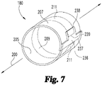
- Sensing band 180 is shown in Fig. 7 removed from the remainder of device 100. Sensing band 180 is exactly circumferentially wrapped around the axis of rotation 200 so as to minimize the use of axial space within device 100 devoted to sensing system 175. Band 180 can alternatively have its ends axially offset so that band 180 is arranged as a helix. Sensing band 180 is operational to sense wiper 185 at any point along the angular length of sensing band 180 at which electrical strips 209 and 211 are present and capable of being brought into electrical contact by a radial deflection caused by wiper 185. Sensing band 180 has an electrical characteristic correlated with where along its angular operational length it is operationally engaged due to the physical contact with wiper 185.
- the angular operational length of sensing band 180 for which sensing is effective is less than 360 degrees around the axis of rotation 200 for the wrapping of the band 180. This length is due to end region 236 of spacer 213 proximate the first end 237 of band 180, at which region there is no sensing. This spacer end region 236 is overlapped by the opposite second end 238 of band 180, with sensing band 180 being sized such that effective portions of electrical strips 209 and 211 proximate the opposite end region 239 of spacer 213, while not angularly overlapping spacer end region 236, stop immediately before such an overlapping as shown in Fig. 7 .
- the operational angular length extends less than 360 degrees around the housing inner circumference, and in particular 360 degrees minus the portion of the inner circumference spanned by the spacer end region 236.
- One suitable operational length extends at least 345 degrees.
- the effective length of the electrical strips 209 and 211 can overlap end region 236.
- Controller 170 includes a microprocessor 240 electrically circuited with sensing band 180 as shown schematically in Fig. 8 .
- the electrical outputs from the sensing band 180 that reach microprocessor 240 are processed by the microprocessor to identify the amount of the dose set by operation of the device 100, specifically based on the microprocessor 240 determining relevant movement of the drive assembly 156 relative to the main housing 102 during dose setting.
- an electrical power source 250 such as a 1.8 volt source, that is housed within device 100 within controller 270 is circuited at node 242 with lead 222 from resistor element 211 which acts as an input to sensing band 180.
- the output lead end 235 of conductor element 209 is circuited at node 256 to an input port 258 of the electrically grounded microprocessor 240 through a signal amplifier 260.
- Node 256 is grounded through a voltage divider resistor 262 to provide a voltage to the microprocessor 240 that is proportional to the resistance between nodes 256 and 242.
- the output lead 228 of resistor element 211 is circuited at node 244 to a second input port 246 of the electrically grounded microprocessor 240 through signal amplifier 250, and node 244 is grounded through a voltage divider resistor 252 to provide a voltage to the microprocessor 240 that is proportional to the resistance between nodes 244 and 242.
- controller 170 can determine the relative positions of the members sensed by sensing system 175, namely the drive assembly 156 and the housing 102.
- the shown circuitry results in a differential voltage signal being provided at inputs 246 and 258 to the microprocessor 240 that can be used to compensate for any variations in the output of sensing band 180 that can occur over time or due to environmental conditions.
- a circuitry differential signal can not be required with a sensing band in an alternate embodiment.
- sensing band 180 being less than three hundred sixty degrees results in a sensing gap around the housing inner circumference. Unless the wiper has an angular length larger than the sensing gap, there is time during the circumferential travel of the wiper that the presence of wiper 185 cannot be actually sensed by the sensing system 175.
- the controller 170 can be programmed to understand that sensing system 175 not outputting a wiper engagement in fact corresponds to wiper 185 being aligned with the sensing gap. If such a programming is not desired, or if the sensing gap is larger than the angular resolution needed for a particular application, an alternate sensing system can be employed.
- sensing system 175' can be used in place of sensing system 175 in device 100 to sense the relative positions of housing 102 and drive assembly 156.
- Sensing system 175' includes first and second sensing bands 180a and 180b each the same structurally as sensing band 180 with electrical circuiting to the device controller but not each other.
- Sensing bands 180a and 180b are coaxially arranged and each is in an exact circumferential arrangement around axis of rotation 200.
- Sensing bands 180a and 180b are closely spaced axially with the electrical strips of each band 180a and 180b not being in an axially overlapping relationship with the electrical strips of the other.
- Sensing band 180a includes a resistor element 211a and a conductor element 209a
- sensing band 180b includes a resistor element 211b and a conductor element 209b.
- the angular operative length of each of band 180a and 180b is shown in Fig. 9 as being the same as band 180, and each of such lengths extends only partially around a circumference of the drive assembly 156.
- Such a configuration results in sensing band 180a having a sensing circumferential gap 181a and sensing band 180b having a sensing circumferential gap 181b.
- the operative lengths of bands 180a and 180b are shown as being equal, such is not required so long as one sensing band covers the sensing circumferential gap of the other.
- the wiper of sensing system 175' is shown as a single, axially extending element 185' that engages both sensing bands 180a and 180b. Different axial regions of wiper 185' engage different sensing bands 180a and 180b.
- the wiper need not be a single continuous member as shown in Fig. 10 but instead can be two distinct wipers, or can have an interruption along its axial length which does not interfere with the operation of engaging the sensing bands 180a and 180b as appropriate.
- Sensing bands 180a and 180b are angularly staggered as shown in Fig. 9 such that sensing circumferential gaps 181a and 181b do not line up at all axially.
- Controller 170 is programmed to understand from the combination of outputs from sensing bands 180a and 180b where the wiper 185', and therefore the drive assembly 156, is located relative to the housing 102. The controller 170 can also use the combination of outputs to determine if one of the sensing bands is not operating correctly.
- Sensing bands 180a and 180b are shown in Figs. 9 and 10 as being separately formed and positioned within a device.
- the resistor elements, conductor elements and leads of the shown two sensing bands can all be provided on appropriately sized and shaped, common substrates, and with an appropriate common spacer. This construction results in a single sensing band, with two sets of angularly staggered resistor and conductor elements, each set with their own electrical contacts for circuiting to the device controller but not the other set, which can be handled as a single unit.
- the sensing circumferential gaps of the two, or even more, sensing bands can be axially aligned.
- the wiper element would have portions on different axial segments of the drive assembly 156, which wiper portions would be appropriately angularly spaced around the drive assembly 156 so as to not all simultaneously engage the sensing gaps of the multiple sensing bands.
- Fig. 11 there is shown in perspective view an alternate medication delivery device with sensing system.
- the sensing system is incorporated into a dose delivery detection module, generally designated 400, that is detachably mounted over the proximal end of the remaining portion of the delivery device, generally designated 405.
- module 400 When module 400 is mounted as shown, its sensing system abstractly represented at 410 in Fig. 11 detects relative rotational positions of module housing parts, and thereby relative rotational positions of first and second members of device portion 405, during dose delivery and generates outputs correlated to such relative rotational positions which are used by controller 415 to identify the dose delivered by operation of the device.
- Fig. 12 shows module 400 either prior to its releasable mounting to device portion 405, or after having been demounted from device portion 405.
- sensing system 410 includes a wiper 420 and a sensing band 425.
- Wiper 420 is coupled to and projects radially inwardly from an interior circumferential surface 432 of a module housing part 450.
- Sensing band 425 is coupled to and rings the radially outer periphery or surface 434 of module housing part 455.
- Sensing band 425 is shown in Fig. 13 as being axially offset slightly above the axial center of wiper 420 due to housing part 455 shifting axially downward relative to housing part 450 during dose delivery in an amount equal to the axial offset shown in Fig. 13 , which figure represents the device as configured before a dose setting.
- sensing band 425 and wiper 420 are completely radially aligned.
- Sensing band 425 is electrically connected with not shown wiring to controller 430 secured within an interior hollow 457 of housing part 455.
- controller 430 secured within an interior hollow 457 of housing part 455.
- wiper 420, sensing band 425 and controller 430 are structured and function similarly to the corresponding wiper 185, sensing band 180 and controller 170 of device 100.
- Module housing part 450 includes a connection 460 complementarily shaped to a skirt 500 of the dose dial assembly 502 for a removable mounting of module 400 to the remaining portion of the delivery device 405.
- Skirt 500 is shown separately formed from but is fixedly secured, both rotatably and axially, with the dose dial assembly 502, and the connection 460 results in housing part 450 being rotatably and axially fixed with the dial assembly 502.
- Module housing part 455 includes a base face 465 that engages a top surface 504 of a button 506 to be rotatably fixed therewith.
- module 400 is rotated relative to pen housing 508, which screws dial assembly 502 and button 506 upward and together relative to the pen housing 508.
- a splined connection indicated at 464 between housing parts 450 and 455 aids in keeping these housing parts rotating together during dose setting.
- housing part 455, as well as button 506 are moved downward without rotation relative to housing part 450 and the dial assembly 502.
- This motion disconnects the splined connection 464 as well as a not shown clutch connection between button 506 and dial assembly 502, and causes an alignment of sensing band 425 with wiper 420.
- Further plunging moves housing part 455 and button 506 axially downward without rotation while simultaneously screwing the housing part 450 and the dial assembly 502 back into pen housing 508.
- the relative rotation of housing parts 450 and 455 is sensed by the operative interaction of wiper 420 with sensing band 425, which allows the controller 430 to determine the dose delivered.
- Device portion 405 may be equivalent to a Humalog ® KwikPen ® from Eli Lilly and Company, which is taught in U.S. Patent No. 7,291,132 . Further details of dose delivery detection module 400 will be appreciated from United States Provisional Patent Application No. 62/362,808 filed July 15, 2016 , entitled DOSE DETECTION MODULE FOR A MEDICATION DELIVERY DEVICE.
- Figs. 14-21 there is shown pertinent parts of an alternate medication delivery device with sensing system, generally designated 600.
- the sensing system of device 600 is configured to determine both the amount of the dose set and the amount of the dose delivered by operation of the device.
- device 600 can be configured the same as device 100.
- the description of device 600 includes further details of the configuration of its mechanical drive assembly corresponding to assembly 156 of device 100, as well as further details of the sensing system suited for mechanical drive assemblies of such type.
- Reference to parts that are the same as in device 100 use the same reference numbers as used with device 100 to facilitate explanation.
- the device sensing system is visible within a housing compartment 622 due to a portion of the exterior main housing 624 having been removed.
- Housing compartment 622 is shaped to receive the sensing system 620 and includes alignment ribs 644 and 646 that project radially inward to support core member 650 and maintain it rotationally and axially fixed relative to the housing 624.
- Sensing system 620 is coupled to select members of device 600 which are relatively rotatable in proportion to the amount of the set dose, and which are relatively rotatable in proportion to the amount of the injected or delivered dose. These members include barrel 660, drive sleeve 665 and core member 650.
- barrel 660 is a sleeve that is keyed to rotate with, but be axially movable relative to, tube 154.
- the drive sleeve 665 includes external threading 670 that is engaged by internal threading of tube 154.
- An internal axial hollow 672 of drive sleeve 665 receives threaded shaft 165 therein.
- a not shown keying between drive sleeve 665 and threaded shaft 165 means that a rotation of drive sleeve 665 within housing compartment 622 causes a corresponding rotation of shaft 165 which advances that shaft axially to eject medication from the device 600.
- barrel 660 rotates within the housing 624 about axis of rotation 674 while drive sleeve 665 does not rotate about axis of rotation 674 due to a not shown spline connection between the device housing 624 and drive sleeve 665.
- sensing system 620 includes sensing bands 680 and 700.
- Sensing band 680 includes a wiper sensing portion 682 formed in a cylindrical sleeve shape, and a connector leg 684.
- the sensing portion 682 is a single assembled unit including two angularly staggered pairs of conductor-resistor strips extending circumferentially within the sleeve similarly to that described above for sensing bands 180a and 180b.
- sensing portion 682 can be constructed similarly to sensing band 180.
- Connector leg 684 contains the electrical leads circuited with the associated two conductor-resistor strip pairs.
- Connector leg 684 includes a first region 686 that extends directly from the sensing portion 682 in an axial direction.
- a transition region 688 extends in the angular direction from first region 686 and terminates in an end region 690 that includes not shown electrical connections that can be a printed extension of lead end 228 and can be circuited with the electrical leads, such as a ZIF (Zero Insertion Force) connecter, that are circuited with the conductor-resistor strip pairs of sensing portion 682.
- the electrical connections are provided on the outer radial periphery of end region 690 for electrical connection during assembly with circuity routed to the controller of device 600.
- First region 686 is arranged in the same curved plane as sensing portion 682, while transition region 688 juts outward from first region 686 in the radial direction. End region 690 extends from transition region 688 to lay over the core member exterior to enable electrical connection to the rest of the circuitry with the ability to transition into a flat connection.
- Sensing band 700 includes a wiper sensing portion 702 formed in a cylindrical sleeve shape, and a connector leg 704. Wiper sensing portion 702 has a larger diameter than wiper sensing portion 682 to fit around it.
- Sensing band 700 is a single assembled unit including two angularly staggered pairs of conductor-resistor strips extending circumferentially within the sleeve similarly to that described above for sensing bands 180a and 180b, but typically with the conductor strips located radially outward of their respective resistor strips.
- sensing portion 702 can be constructed similarly to sensing band 180, with the resistor and conductor strips typically reversed.
- Connector leg 704 contains the electrical leads circuited with the associated two conductor-resistor strip pairs.
- Connector leg 704 includes a first region 706 that extends directly from the sensing portion 702 in an axial direction and in the same curved plane as sensing portion 702.
- a transition region 708 extends in the angular direction from first region 706 with an offset to extend outward radially to allow a service loop to aide in connection of 710 to other circuitry.
- End region 710 of connector leg 704 extends in a curved shape from transition region 708 to lay over the core member exterior and includes not shown electrical connections, as previously described in relation to end region 690, on its outer radial periphery circuited with the electrical leads within the connector leg 704 and for electrical connection during assembly with circuity routed to the controller of device 600.
- Core member 650 is formed in one-piece of a rigid plastic and includes an interior bore or hollow therethrough 652.
- Core member 650 has a sleeve portion 720 with a cylindrical, radially inner periphery or surface 722 and a cylindrical, radially outer periphery or surface 724.
- Core member 650 includes keyed portion 730 at the distal end of sleeve portion 720.
- Keyed portion includes a cylindrical, radially inner surface 732 that is an axial continuation of sleeve portion surface 722.
- the radially outer surface 735 has channeled sections 736 that fit over alignment ribs 644 and 646 to provide alignment for installation within the housing compartment 622 and to prevent core member 650 from rotating or shifting axially within housing 624 during use. While core member 650 is shown as a single piece that is effectively connected to the housing, such a design is not necessary but facilitates manufacture and assembly. In alternate embodiments, a core member can be integrally formed with the outer housing, or formed of multiple parts assembled together and then installed to the housing.
- Sensing bands 680 and 700 are each mounted to core member 650 to be rotationally and axially fixed with core member 650, and therefore indirectly axially and rotationally fixed with housing 624.
- Such mounting can be with adhesives, or an alternate manner such as mechanical fasteners or a friction fit.
- Sensing band 680 is arranged such that wiper sensing portion 682 wraps along or layers the full circumference of the cylindrical radially inner surface 722, connector leg first region 686 extends along cylindrical radially inner surface 732, transition region 688 fits through a slot-shaped opening 740 provided through keyed portion 730 by a notch 742 in its distal end 744, and end region 690 overlays radially outer surface 735.
- Sensing band 700 is arranged such that wiper sensing portion 702 is radially aligned with and radially outward of wiper sensing portion 682 and directly sandwiching core sleeve portion 720 therebetween such that the two sensing layers provided by sensing bands 680 and 700 are separated only by core sleeve portion 720.
- Wiper sensing portion 702 wraps along the full circumference of the cylindrical radially outer surface 724, with connector leg first region 706, transition region 708 and end region 710 overlaying radially outer surface 735 of keyed portion 730.
- a wiper element 750 coupled to drive sleeve 665 that extends through core bore 652 is positioned radially inward of and slidingly engages wiper sensing portion 682.
- Wiper element 750 is rigid and has a suitable axial length to effectively engage the wiper sensing portion 682 at all times of device operation. Such a design allows the drive sleeve rotational position to be checked even when it should not be rotating during a dose setting.
- Wiper element 750 projects radially outward from a stepped arm 752 that extends axially from a C-shaped clip or mount 754.
- a cut-out or depression 675 in the periphery of drive sleeve 665 underneath the wiper element 750 and arm 752 serves as clearance for arm 752 to flex.
- Wiper element 750, arm 752 and clip 754 are shown integrally formed, but can be separately formed and assembled.
- the material of the arm 752 and clip 754 can be a pressed stainless steel that affords sufficient resiliency for a flexing of arm 752, which flexing provides a spring loaded engagement of wiper element 750 with sensing band 680 as well as accounts for non-concentricity, and for attachment of clip 754 to drive sleeve 665.
- Wiper clip 754, and therefore arm 752 and wiper element 750, are rotationally and axially fixed to drive sleeve 665 via a projection 758 of drive sleeve 665 that closely fits within a complementary hole 760 in clip 754, with the resiliency of the C-shaped clip 754 gripping around the drive sleeve 665 radially periphery.
- clip 754 is resiliently splayed open by wedge feature 770, allowing clip 754 to be moved axially so that hole 760 fits above and then onto projection 758, at which axial position clip 754 has passed wedge feature 770 so as to snap back around the drive sleeve 665 to secure the clip as shown in Fig. 20 .
- a wiper element 780 coupled to barrel 660 is positioned radially outward of and slidingly engages wiper sensing portion 702. As shown in Fig. 16 , the wiper element 780 can extend in an axially different direction than the wiper element 750. As shown in Fig. 16 , the wiper element 780 can radially overlap the wiper element 750, being separated by the sidewall of the sleeve portion 720 of the core member 650. Wiper element 780 is positioned radially outward from wiper element 750. Wiper element 780 is rigid and has a suitable axial length to effectively engage sensing band 700 at all times of device operation. Such a design allows the barrel rotational position to be checked even when it should not be rotating during a dose injection.
- Wiper element 780 projects radially inward from a stepped arm 782 that extends axially from a C-shaped clip 784.
- Wiper element 780, arm 782 and clip 784 are shown integrally formed, such as from pressed stainless steel, but can be separately formed and assembled.
- Arm 782 is flexible and provides a spring loaded engagement of wiper element 780 with sensing band 700 and to account for non-concentricity.
- Wiper clip 784, and therefore arm 782 and wiper element 780 are rotationally fixed to barrel 660 by a keyed connection using a notch 790 in clip 784 and a space 792 between the ends 793 of the two clip legs to closely receive two tangs 794 that project inward within the hollow 798 of barrel 660.
- Wiper clip 784, and therefore arm 782 and wiper element 780 are shown axially fixed to barrel 660 by axially extending, detented springs 797 that snap fit into indents 799 on the barrel interior surface, but can be alternatively secured such as using adhesive or mechanical fasteners, such as radial crimps.
- wiper element 780 with sensing band 700 allows a rotation of the barrel 660 relative to the core member 650 and housing 624 to be sensed to allow a dose set for device 600 to be identified by a controller
- wiper element 750 with sensing band 680 allows a rotation of the drive sleeve 665 relative to the core member 650 and housing 624 to be sensed to allow a dose delivered for device 600 to be identified by the controller.
- Figs. 23-25 there is shown pertinent parts of an alternate medication delivery device with sensing system.
- the device of Figs. 23-25 also is configured to determine both the amount of the dose set and the amount of the dose delivered by operation of the device.
- the device of Figs. 23-25 uses a a modified sensing band having different regions of common electrical strips cooperating with a pair of wiper elements. It will be appreciated that the device of Figs. 23-25 can be similar in overall operation to device 600.
- the device includes a barrel 850, a drive sleeve 860 that transmits its rotation, via a not shown mechanical drive train, to a not shown threaded shaft used to eject medication, and a core member 890 that is rotationally fixed to the device housing and axially unconstrained to the device housing such that it can slide axially relative to the device housing.
- a wiper assembly is fixedly coupled to drive sleeve 860 to rotate and move axially therewith, and to extend within bore 898 of core member 890.
- Wiper assembly 880 includes a pair of wipers 882 and 884, each formed of a wiper element on a flexible arm. The wiper elements of wipers 882 and 884 are shown as outwardly facing, convex surfaces projecting from the arms, but need not be so shaped or projecting.
- Wipers 882 and 884 extend axially from and are integrally formed with a C-shaped clip or mount 886 at locations 180 degrees apart from each other. Wiper 882 extends further axially from mount 886 than does wiper 884 as further described below.
- Wiper 882 can flex within depression 862 of drive sleeve 860 while wiper 884 similarly can flex within a depression on the side of drive sleeve 860 opposite depression 862.
- Wiper mount 886 secures around axial portion 863 of drive sleeve 860 so that wiper assembly 880 rotates with the drive sleeve, and wiper assembly 880 does not move axially relative to drive sleeve 860, such as due to the axial capture of wiper mount 886 via a shoulder 861 formed on drive sleeve 860 and frictional interaction on the internal face of wiper mount 886.
- a wiper assembly is fixedly coupled in a suitable fashion to barrel 850 so as to rotate and move axially therewith .
- Wiper assembly 870 includes a pair of wipers 872 and 874, each formed of a wiper element on a flexible arm.
- the wiper elements of wipers 872 and 874 are shown as strip-engaging surfaces of their respective wiper arms, but can project from such arms.
- Wipers 872 and 874 extend from and are integrally formed with a wiper ring, which ring is shown as having keys 876 that closely fit within angular spaces between the opposite angular ends of arc-shaped extensions 854 of barrel 850.
- Wipers 872 and 874 are circumferentially disposed relative to one another substantially 180 degrees (that is, in a range of 180 degrees plus/minus 10 degrees). In one example, wipers 872 and 874 extend axially at locations 180 degrees apart from each other. Wiper 874 extends further axially forward than does wiper 872 (that is, axially offset from one another) as further described below.
- Core member 890 is constrained to move axially with drive sleeve 860 and barrel 850 when drive sleeve 860 and barrel 850 move together axially within the device housing during mode transitioning of the device.
- core member 890 is driven forward within the device housing by a thrust face of wiper assembly 870 when the device transitions from dial mode to injection mode.
- Clip 920 is an axial thrust washer/clip that locks onto the drive sieve 860 and is used to pull core member 890 back within the device housing when the device returns to dial mode after being in injection mode.
- Each of wiper assemblies 870 and 880 cooperates with a different sensing band, each of which sensing bands has a single pair of particularly shaped conductor-resistor strips extending therein that are shaped to have different regions be engaged by the wiper elements of the wiper assemblies.
- wiper assembly 870 cooperates or functions with a sensing band, generally designated 891, that wraps around the exterior of core member 890.
- Wiper assembly 880 cooperates with a sensing band shown in cross section in Fig. 24 and generally referenced 897 which wraps the interior of core member 890.
- Each sensing band 891 and 897 is rotationally and axially fixed with core member 890 and therefore indirectly rotationally fixed to the device housing.
- the sensing bands 891 and 897 are mounted on the core member 890 similarly to the manner that sensing bands 680 and 700 fit within, around and through core member 650.
- sensing band 891 With additional reference to the flattened configuration of the sensing band shown in Fig. 25 , the construction and design of sensing band 891 will be further explained. This explanation of sensing band 891 also applies to sensing band 897 which is similarly configured, though sensing band 891 works with wiper assembly 870 to sense barrel position while sensing band 897 works with wiper assembly 880 to sense drive sleeve position.
- Sensing band 891 is shown including a sensing portion 892 that holds the sensing strip pair and which when installed is in a cylindrical sleeve shape. Connector leg 899 is used for making an electrical connection between the sensing strip pair within sensing portion 892 and the device controller.
- the effective shape of the pair of conductor-resistor strips extending within sensing portion 892, and thereby the effective sensing area of sensing portion 892, is shown in Fig. 25 in dashed lines.
- the sensing area includes a main path 893 and a secondary path 902 that are different regions of the same electrical strips so as to be electrically integrated, thereby allowing the controller to receive a single electrical output from the sensing band 891 whether produced by the the main path 893 or the secondary path 902.
- Main path 893 continuously extends between angular ends 894 and 896.
- Main path 893 is axially positioned within the device to be axially operatively aligned for contact with the wiper element of wiper 872.
- Main path 893 is never contacted by wiper 874 as barrel 850 is rotated during use.
- the main path 893 almost completely rings the core member periphery.
- the only periphery portion not ringed is a small angular region or gap 895 of that periphery between the facing angular ends 894 and 896.
- the device controller is able to determine where along the angular length of main path 893 the wiper element of wiper 872 operatively contacts the main path 893, allowing a position of the barrel 860 relative to the core member 890 to be sensed to allow a dose set for the device to be identified by the controller.
- Secondary path 902 continuously extends between angular ends 904 and 906 and juts directly from main path 893 in the axially forward direction. Secondary path 902 is axially positioned within the device to be axially operatively aligned for contact with the wiper element of wiper 874, and is never contacted by wiper 872. Secondary path 902 has an angular length extending between ends 904 and 906 which covers the length of the angular gap 895.
- Secondary path 902 is positioned along the angular length of main path 893 in view of the angular spacing beween the wiper elements of wipers 872 and 874 so as to realize a design in which wiper 874 engages secondary path 902 at all times wiper 874 is within angular gap 895 and not operatively contacting main path 893.
- Secondary path 902 is shown positioned halfway along the angular length of main path 893 due to wipers 872 and 874 begin spaced 180 degrees apart around the core member 890, but in alternate embodiments can be positioned differently to account for different angular spacings of the wipers.
- the secondary path 902 maybe formed as a separate second sensing band (not shown) axially disposed adjacent to the main path 893 of the first sensing band.
- the separate second sensing band is contactedly associated with the wiper 874, while the first sensing band with main path 832 is contactedly associated with the wiper 872.
- the device controller recognizes barrel rotational position from the single electrical signal it receives from sensing band 891. During the majority of barrel rotation, the magnitude of the electrical signal to the device controller reflects where the wiper 872 engages main path 893, during which time wiper 874 is not engaged with secondary path 902. When wiper 872 enters the rotary gap 895 to no longer engage main path 893, the wiper 874 simultanesously engages secondary path 902 to short the signal to the controller notably differently from where the signal was being shorted by wiper element 872 immedicately prior.
- This changed signal value, as well as the value of that signal as it further changes as the wiper 874 moves along the angularly length of secondary path 902, allows the controller to recognize barrel rotational position until the the wiper 872 again engages main path 893 while the wiper 874 moves off secondary path 902.
- secondary path 902 can have an angular length longer, such as a few degrees longer, than the angular length of gap 895.
- angular length such as a few degrees longer
- wiper 874 engages the few degrees longers section of the secondary path 902 while wiper 872 also engages main path 893.
- sensing band 891 can introduce uncertainty for the controller, such as the output signal being generated by sensing band 891 being an averaging of the signals otherwise sent by wipers 874 and 872 contacting their respective paths.
- This uncertainty can be resolved in the device by an initialization action involving active rotation of the wiper over a sufficiently large angular distance as to provide the controller with a continuous characteristic signal from sensing band 891 to enable the controller to resolve a known reference position.
- the module 400 can sense dose setting amounts if adapted to work with a device portion having suitable parts that experience relative rotation during dose setting.
Landscapes
- Health & Medical Sciences (AREA)
- Vascular Medicine (AREA)
- Engineering & Computer Science (AREA)
- Anesthesiology (AREA)
- Biomedical Technology (AREA)
- Heart & Thoracic Surgery (AREA)
- Hematology (AREA)
- Life Sciences & Earth Sciences (AREA)
- Animal Behavior & Ethology (AREA)
- General Health & Medical Sciences (AREA)
- Public Health (AREA)
- Veterinary Medicine (AREA)
- Infusion, Injection, And Reservoir Apparatuses (AREA)
Description
- The present disclosure pertains to medication delivery devices, and, in particular, to a sensing system in a medication delivery device.
- A variety of medication delivery devices, including for example pen injectors, infusion pumps and syringes, are commonly used for periodic administration of medications. It is important that the proper amount of medication be supplied at these times as the health of the patient is at stake. In many instances, failure to accurately deliver the appropriate amount of medication may have serious implications for the patient.
- The administration of a proper amount of medication requires that the actual dosing by the medication delivery device be accurate. The term "dosing" as used herein refers to two phases of administering a dose, namely, setting the dose amount and delivering the amount of the set dose.
- Medication delivery devices often utilize mechanical systems in which various members rotate or translate relative to one another. In most instances, these relative movements between members are proportional to the dose amount set and/or delivered by operation of the device. Accordingly, the art has endeavored to provide reliable systems that accurately measure the relative movement of members of a medication delivery device in order to assess the dose set and/or delivered.
- While useful, prior art sensing systems are not without their shortcomings. For instance, some sensing systems take up more space within a delivery device than is desirable, resulting in a delivery device that is more bulky or inconvenient to use, or in a delivery device that has to sacrifice one or more features to have room in a compact device for the sensing system. Some sensing systems use relatively expensive componentry, or may be overly complicated so as to adversely impact the cost of manufacture or potentially the system reliability.
- Thus, it would be desirable to provide a medication delivery device with a sensing system that can overcome one or more of these and other shortcomings of the prior art.
-
US 2015/343152 A1 discloses a decoding system for use with a drug delivery device having a drug dose dialing mode and a drug dose delivery mode. The decoding system has a first sensor configured to read encoded information from a first rotatable component of the drug delivery device, and a second sensor configured to readencoded information from a second rotatable component of the drug delivery device. The second sensor comprises an optical sensor configured to be directed at the second rotatable component, and a processor. The processor is configured to receive signals from the first and second sensors, and to determine from the received signals whether the drug delivery device is in a drug dose dialing mode or a drug dose delivery mode. -
US 2015/367077 A1 discloses a drug delivery system comprising drug expelling means adapted to expel a set dose from a drug-filled cartridge. The expelling means comprises a rotational member adapted to rotate relative to a housing and corresponding to a set and/or expelled dose. The system comprises a sensor adapted to detect a set and/or an expelled dose. The sensor comprises a first portion mounted to and rotating with the rotational member, and a second portion comprising a second rotary sensor part mounted non-rotationally relative to the housing. The first portion comprises electronic circuitry, and a first rotary sensor part, and the second portion comprises a second rotary sensor part mounted non-rotationally relative to the housing. The first and second rotary sensor parts rotate relative to each other during set- ting and/or expelling of a dose of drug. -
US 2008/140018 A1 discloses a medication delivery system. A movable part is adapted to move relative to a stationary part. At least two conductors are arranged such that an electrical characteristic is defined by the mutual position of the movable and the stationary part and/or by movement of one of said parts relative to the other. A detector detects a change of the electrical characteristic. The parts are stationary relative to each other during dose setting and the parts are moved relative to each other during dose ejection, such that that detector provides a signal indicative of the actual amount of the ejected dose. -
US 2004/207385 A1 discloses a device for detecting the position of a rotor relative to a stator. At least one electrode is arranged on the rotor and at least one electrode is arranged on the stator, such that the electrodes at least partially overlap in at least one rotational position of the rotor relative to the stator.WO 02/092153 - The invention is defined in claim 1. Further aspects and preferred embodiments are defined in the dependent claims. Aspects, embodiments and examples of the present disclosure which do not fall under the scope of the appended claims do not form part of the invention and are merely provided for illustrative purposes.
- Advantages and objects of this invention, and the manner of attaining them, will become apparent, and the invention itself will be better understood, by reference to the following description of embodiments of the invention taken in conjunction with the accompanying drawings, wherein:
-
Fig. 1 is a perspective view of a medication delivery device in the form of an injection pen without a cap and prior to a mounting of a needle assembly; -
Fig. 2 is a side view in partial cross-section of the injection pen ofFig. 1 with a needle assembly attached and after a dose for delivery has been set; -
Fig. 3 is an abstract cross-sectional view taken along line 3-3 ofFig. 2 further showing a sensing system; -
Fig.4 is a partial, abstract cross-sectional side view of the injection pen ofFig. 1 ; -
Fig. 5 is a perspective view ofFig. 3 ; -
Fig. 6 is an exploded perspective view of the sensing band of the sensing system in an uncurved, or straight, configuration; -
Fig. 7 is a perspective view of the sensing band ofFig. 6 in a ring-shaped configuration; -
Fig. 8 is a schematic of an electrical circuiting of the sensing system with the controller microprocessor; -
Fig. 9 is an abstract perspective view of another configuration of sensing bands of a sensing system; -
Fig. 10 is a partial, abstract cross-sectional view similar toFig. 4 of the sensing system bands ofFig. 9 and a suitable wiper installed in the device ofFig. 1 ; -
Fig. 11 is a perspective view of an alternate embodiment of a medication delivery device with sensing system; -
Fig. 12 is a partial perspective view of the device ofFig. 11 showing the dose delivery detection module detached from the remainder of the device; and -
Fig. 13 is a cross-sectional view, taken along line 13-13 inFig. 11 , of the dose delivery detection module, with a portion of the remainder of the device shown not in cross-section. -
Fig. 14 is a partial perspective view, and with a region removed to reveal the interior, of an alternate embodiment of a medication delivery device with sensing system; -
Fig. 15 is a partial perspective view of select portions of the device with sensing system ofFig. 14 ; -
Fig. 16 is a longitudinal cross-sectional view taken along line 16-16 ofFig. 15 ; -
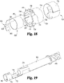
Fig. 17 is a perspective view similar toFig. 15 showing only the sensing bands and the core member; -
Fig. 18 is an exploded perspective view of the components shown inFig. 17 ; -
Fig. 19 is a partial, exploded perspective view of a wiper component and drive sleeve of the medication delivery device with sensing system ofFig. 14 ; -
Fig. 20 is a partial, opposite perspective view of the wiper component and drive sleeve ofFig. 19 ; -
Fig. 21 is a partial and exploded perspective view of a wiper component and barrel of the medication delivery device with sensing system ofFig. 14 ; -
Fig. 22 is a partial perspective view of the wiper component and barrel ofFig. 21 ; -
Fig. 23 is a perspective view, in partially exploded form, of portions of an alternate embodiment of a medication delivery device with sensing system; -
Fig. 24 is a partial perspective view, partially in longitudinal cross-section, of the device portions ofFig. 23 within a housing piece; and -
Fig. 25 is an abstract view of a sensing band of the sensing system fromFig. 23 in an uncurved, or straight, configuration. - Corresponding reference characters indicate corresponding parts throughout the several views. Although the drawings represent embodiments of the present invention, the drawings are not necessarily to scale, and certain features may be exaggerated or omitted in some of the drawings in order to better illustrate and explain the present invention.
- Referring now to
Figs. 1-2 , there is shown a medication delivery device equipped with a sensing system that is described further as being used to determine the amount of a dose set by operation of the device. Such amount is determined based on the sensing of relative rotational movements during dose setting between members of the medication delivery device, where the sensed movements are correlated as applicable to the amount of the dose set. In different embodiments, the sensing system is configured to determine the amount of at least one of the dose set and the dose delivered by operation of the device, or alternatively both the amount of the dose set and the amount of the dose delivered by operation of the device. One of the advantages of the disclosed embodiments is that a medication delivery device with sensing system may be provided that can accurately and reliably assess the amount of medication that has been set and/or delivered by that device. Another of the advantages is that a medication delivery device with sensing system maybe provided that requires a limited number of individual parts. Still another of the advantages is that a medication delivery device with sensing system may be provided which has a compact form factor. - The shown device is a reusable pen-shaped medication injection device, generally designated 100, which is manually handled by a user to selectively set a dose and then to inject that set dose. The description of
device 100 is merely illustrative as the sensing system can be adapted for use in variously configured medication delivery devices, including differently constructed pen-shaped medication injection devices, differently shaped injection devices, and infusion devices. The medication may be any of a type that may be delivered by such a medication delivery device.Device 100 is intended to be illustrative and not limiting as the sensing system described further below may be used in other differently configured devices.Device 100 is similar in many respects to a device described inU.S. Patent No. 7,195,616 . - As used herein, the term "coupled" encompasses any manner by which a first item is caused to move in unison with or in proportion to a second item as the second item moves. Items are rotationally coupled if they are caused to rotate together. Coupling systems may include, for example, connections provided through splines, gears or frictional engagement between the members, or similar connections provided by other components which indirectly couple the members. Where applicable, an item may be coupled to another item by being directly positioned on, received within, attached to, or integral with the other item, or otherwise secured thereto, directly or indirectly.
- The term "fixed" is used to denote that the indicated movement either can or cannot occur. For example, a first member is "rotatably fixed with" or "fixed against rotation relative to" a second member if the first member is not able to rotate relative to the second member.
-
Medication injection device 100 includes an outer housing that supports the internal components of the device. The housing is shown as having a rear ormain housing 102 and a forward or cartridge housing 104.Main housing 102 is configured to hold a drive assembly of the device, which assembly is a strictly user powered, mechanical assembly as described but may in alternate embodiments be a motorized assembly. Cartridge housing 104, also known as the cartridge retainer, holds acartridge 106 filled with medication to be delivered by device operation. Cartridge retainer 104 is detachably connectable or mountable tomain housing 102 viaexternal threading 110 on a protrudingcollar portion 112 ofmain housing 102 which mates withinternal threading 114 on aring portion 116 at the proximal end of cartridge retainer 104. Suitable detachable connecting elements other thanthreadings - Cartridge retainer 104 includes an internal hollow 105 suited to removably receive
cartridge 106, thereby allowing a cartridge to be inserted therein, and then removed therefrom when depleted and replaced with a fresh cartridge of similar design.Openings 118 in cartridge retainer 104 allow visibility of the cartridge contents. Adetent feature 120 provided on the exterior of cartridge retainer 104 allows for a not shown protective cap to be detachably mounted over the cartridge retainer 104 when aneedle assembly 125 is not attached to the cartridge retainer 104. Although cartridge retainer 104 is described herein as being a reusable component, the cartridge retainer 104 can be integrated with, and therefore be disposable with, thecartridge 106. -
Medication cartridge 106 is of conventional design, including abarrel 130 having an interior reservoir filled with medication which is sealed at one end by a slidable plunger orpiston 132 and sealed at the other end by aseptum 134 held by acrimp ring 136. - A
needle assembly 125 detachably mountable to an externally threadeddistal end 122 of cartridge retainer 104 pierces theseptum 134 when so mounted. The pierced septum through which the needle extends serves as an outlet during dispensing for the medication within the reservoir ofbarrel 130, which medication is delivered through theneedle assembly 125 by operation ofdevice 100. Thecartridge 106 can hold multiple doses of medication, or even a single dose, depending on the purpose ofdevice 100. -
Medication injection device 100 is shown inFig. 1 in its "zero position" at which the device has not been set for delivery of any dose. This zero position setting is indicated by the number "o" visible somewhere on the device, such as, for example, on anelectronic dose display 140 inFig. 1 . InFig. 2 ,device 100 is arranged after being manipulated to set a dose of thirty units for delivery, and the number "30" would be visible, such as, for example, on thedisplay 140. -
Medication injection device 100 is typical of many such reusable devices including a manually-powered dose delivery mechanism, generally designated 150, that controls forward or distal advancement of a drive member, generally designated 160.Drive member 160 advances within thecartridge barrel 130 to directly engage andadvance plunger 132. As shown inFig. 2 ,dose delivery mechanism 150 includes adose knob 152 connected via atube 154 to a mechanical drive assembly abstractly indicated at 156 that is housed withinmain housing 102. Whenknob 152 is turned by a user to set a dose for injection,dose knob 152 andtube 154 screw out together proximally frommain housing 102. When a user applies a plunging distal force on theproximal end 158 ofdose knob 152, the resulting purely translational axial motion ofdose knob 152 andtube 154 distally forward intomain housing 102 is converted bydrive assembly 156 into a smaller motion ofdrive member 160 forward frommain housing 102 into the interior ofcartridge barrel 130. -
Drive member 160 is formed in two pieces including aforward end 163 that directly engages thecartridge plunger 132, and ashaft 165 that axially extends rearward fromforward end 163 intomain housing 102. Theshaft 165 is threaded and is engaged withdrive assembly 156 to be screwed out frommain housing 102 and thereby driven forward.Shaft 165 is shown threadedly engaged with ahousing bulkhead 168, which housing bulkhead is shown integral withmain housing 102 but can be separately formed and fixedly attached thereto.Forward end 163 is provided in the form of an enlarged foot that is mounted onshaft 165 to allow relative rotation, allowingfoot 163 to engageplunger 132 without relative rotation therebetween asshaft 165 screws out. While this foot and shaft two-piece construction ofdrive member 160 is preferred whenshaft 165 screws out from the housing during advancement, such a construction is not required in devices, particularly if the drive member simply translates as it is forced forward from the housing, in which case a single piece drive member construction maybe more acceptable. -
Device 100 uses anelectronic dose display 140 rather than a helically marked dial display as used in many other reusable injection devices.Display 140 is circuited to and controlled by an electronic controller or computingassembly 170 mounted withinmain housing 102.Controller 170 can include conventional components such as a processor, power supply, memory, etc..Controller 170 is programmed to achieve the electronic features ofdevice 100, including causing the display of set doses. The set dose displayed indisplay 140 is determined by the interaction ofdose delivery mechanism 150 with a sensing system, abstractly shown at 175, which is electrically circuited withcontroller 170. - With additional reference to
Figs. 3-5 ,sensing system 175 is coupled to two members ofdevice 100 which, when a dose is set by a user screwingdose knob 152 out fromhousing 102, are relatively rotatable in proportion to the amount of such set dose. Depending on the configuration ofdevice 100 and in particular thedrive assembly 156, those two members ofdevice 100 to whichsensing system 175 is coupled also can be rotatable relative to each in proportion to the amount of a dose delivered by plunging operation ofdose knob 152, and in whichcase sensing system 175 can additionally be used in determining the delivered dose. Alternatively, in another embodiment where dose delivered instead of dose set is sensed,sensing system 175 is positioned for sensing dose delivered by being coupled to two members ofdevice 100 which, during dose delivery, are relatively rotatable in proportion to the amount of dose delivered, but which two members do not relatively rotate during dose setting. -
Sensing system 175 operates to detect relative rotational positions of the first and second device members to which it is coupled and generates outputs correlated to such relative rotational positions.Sensing system 175 includes asensing band 180 and awiper 185. Indevice 100,sensing band 180 is coupled tohousing 102, andwiper 185 is coupled to a part ofdrive assembly 156 that at select times of device use rotates within the housing interior.Sensing band 180 alternatively can be coupled tohousing 102 via one or more intermediate components, and further alternatively can be coupled tohousing 102, either directly or directly, to not rotate relative to the housing but be free to move axially, such as if thewiper 185 with which it engages moves axially during device use andsensing band 180 were attached directly to a component rotatably fixedly, and axially movably, mounted to thehousing 102. - As abstractly shown in
Fig. 3 ,sensing band 180 is directly attached, such as with an adhesive, to the interior circumferential and radially inwardly facingsurface 188 ofhousing 102, whilewiper 185 is directly attached, such as with an adhesive or by being integrally formed therewith, to an outerradial surface 190 of a part of thedrive assembly 156.Drive assembly 156 can take various forms, but typically involves multiple interacting parts, andwiper 185 is shown positioned on a rotatable part of this assembly so as to have direct contacting access to thesensing band 180. -
Wiper 185 includes abody 196 that projects radially outward from itsinward end 194 to itsoutward end 198.Outward end 198 has a rounded apex that provides a precise point of contact for sliding engagement withsensing band 180 along the circumferential extent of the band.Wiper body 196 has an axially extending length parallel to the axis of rotation, indicated at 200, about which rotates the part of thedrive assembly 156 from which the wiper projects. As no electrical current is routed through it,wiper 185 can be formed entirely of an electrically non-conductive material such as a thermoplastic elastomer such as silicone. - The wiper alternatively can be a single point contact, without the axial length as shown. The wiper need not extend the width, as extending in the axial direction, of the resistor strip within
sensing band 180. Providingwiper 185 with an axial length can account for both tolerances within the design of the device as well as axial motion within the device of thewiper 185 relative to thesensing band 180 andhousing 102. - The radial height of
wiper body 185 is designed to span the annular space orgap 202 within the housing interior betweensensing band 180 and driveassembly 156.Wiper 185 projects sufficiently far radially outward to provide at least a minimum application force and thereby operationally engagesensing band 180 as described further below. Such force can be controlled by the manufacturer through the material selection and processing, such as tempering, as well as the geometry of the wiper and its residual compression within 156. To better ensure a proper engagement withsensing band 180 at all angular positions of thedrive assembly 156, and therebywiper 185, relative tohousing 102,wiper 185 can be biased radially outward fromdrive assembly 156. Such a biasing can be provided by a material resiliency resulting from formingwiper 185 out of a durable but elastic material such as a thermoplastic elastomer or butyl rubber with a suitable durometer. The biasing can also or alternatively be provided by an additional spring element acting in a radial direction betweenwiper 185 and driveassembly 156. Still further, a biasing of the sensing bands radially inwardly, such as by placing spring elements to act radially between the outer radial periphery of the sensing bands and the housing radial interior surface, can be done alternatively or additionally. -
Wiper 185 andsensing band 180 are in radial alignment when active to sense relative rotational positions. In device embodiments where for example thedrive assembly 156 moves axially from one state, where thesensing system 175 is not used, to a second state, at which thesensing system 175 is used, thewiper 185 andsensing band 180 can be axially spaced when not being used. - Other wiper shapes than the one shown in
Fig. 3 can be used to activatesensing band 180. Such additional wiper shapes include round protrusions, or journaled disks or cylinders that result in rolling contact withsensing band 180. -
Sensing band 180 is configured to generate an electrical output based on where along its angularly extending operational length it is directly contacted bywiper 185.Sensing band 180 is arranged withinhousing 102 in a curved shape around axis ofrotation 200, and the band is disposed radially outward ofwiper 185.Sensing band 180 is shown inFig. 3 as being annular in shape to extend the full 360 degrees of the housing internal circumference and completely ring the axis ofrotation 200. Alternatively,sensing band 180 can be in a ring shape that does not completely encircle or ring the axis of rotation. -
Sensing band 180 can be formed by a membrane potentiometer manufactured in the curved shape to facilitate assembly withindevice 100 to remove residual stresses. One suitable sensing band is available from Tekscan Incorporated. The membrane potentiometer is an assembly of components that are abstractly shown in an uncurved state inFig. 6 , but descriptions of radial and angular refer to the sensing band in the rounded configuration shown in the other figures. Thesensing band 180 includes first and second substrates or backing strips 205, 207, and first and secondelectrical strips spacer 213.Substrates spacer 213, are made of a pliable plastic that is electrically non-conductive such as PET (polyethylene terephthalate) or a polymide film such as Kapton. Alternatively,spacer 213 can be a printed material deposited directly onto eithersubstrate Spacer 213, which serves to keep theelectrical strips substrates Substrates spacer 213 form the exterior ofsensing band 180, and, when sealed together along their peripheral regions, protectively encasestrips Strips substrates spacer 213, or can be otherwise formed such as screen printed, for example, directly to the substrates. -
Electrical strips sensing band 180 in spaced relationship due to the interposition ofspacer 213. Whenband 180 is in its curved configuration withindevice 100,strip 209 is disposed radially inward ofstrip 211, and absent an external force thestrips opening 214 withinspacer 213. Not shown dielectric projections also can be provided on one of theelectrical strips strips -
Electrical strip 211 is an electrical resistor element that has an electrical resistance that varies linearly along its length that extends from a firstangular end 218 to a secondangular end 220. A firstelectrical lead 222 is circuited with and extends fromend 218, and a secondelectrical lead 224 is circuited with and extends fromend 220.Lead 224 is routed at 226 near the electrical strip side to alead end 228 parallel to lead 222 which facilitates the electrical connection ofsensing band 180 with the device circuitry. -
Electrical strip 209 is an electrical conductor element with very low electrical resistance, such as made of silver, copper or gold, having a length that extends from a firstangular end 230 to a secondangular end 232. A firstelectrical lead 235 is circuited with and extends fromend 230. - While leads 235, 222 and 228 are shown as positioned in an extension of the
substrates -
Strip 209 is sufficiently flexible along its length to allow its deflection in the outward radial direction, at the point where it is acted upon, through thesubstrate 205, bywiper 185, to be in direct physical and electrical contact withelectrical strip 211. This wiper causes a compression, indicated at 219 inFig. 3 , that deflectsstrip 209 radially outward thereat to result inwiper 185 operationally engaging thesensing band 180 by causing an electrical contact betweenstrips electrical leads angular end 218 and the point of contact betweenstrips electrical leads angular end 220 and the point of contact betweenstrips electrical leads leads leads - In an alternate embodiment, and provided
resistor element 211 has flexibility properties similar to that ofconductor element 209 to allow a deflection by wiper engagement,sensing band 180 can be configured to haveresistor element 211 be radially inward ofconductor element 209 in the showndevice 100. -
Sensing band 180 is shown inFig. 7 removed from the remainder ofdevice 100.Sensing band 180 is exactly circumferentially wrapped around the axis ofrotation 200 so as to minimize the use of axial space withindevice 100 devoted tosensing system 175. Band 180 can alternatively have its ends axially offset so thatband 180 is arranged as a helix.Sensing band 180 is operational tosense wiper 185 at any point along the angular length ofsensing band 180 at whichelectrical strips wiper 185.Sensing band 180 has an electrical characteristic correlated with where along its angular operational length it is operationally engaged due to the physical contact withwiper 185. - For the shown embodiment, the angular operational length of
sensing band 180 for which sensing is effective is less than 360 degrees around the axis ofrotation 200 for the wrapping of theband 180. This length is due to endregion 236 ofspacer 213 proximate thefirst end 237 ofband 180, at which region there is no sensing. Thisspacer end region 236 is overlapped by the oppositesecond end 238 ofband 180, withsensing band 180 being sized such that effective portions ofelectrical strips opposite end region 239 ofspacer 213, while not angularly overlappingspacer end region 236, stop immediately before such an overlapping as shown inFig. 7 . As a result, the operational angular length extends less than 360 degrees around the housing inner circumference, and in particular 360 degrees minus the portion of the inner circumference spanned by thespacer end region 236. One suitable operational length extends at least 345 degrees. In an alternate embodiment in which asensing band 180 is longer, the effective length of theelectrical strips end region 236. -
Controller 170 includes amicroprocessor 240 electrically circuited withsensing band 180 as shown schematically inFig. 8 . The electrical outputs from thesensing band 180 that reachmicroprocessor 240 are processed by the microprocessor to identify the amount of the dose set by operation of thedevice 100, specifically based on themicroprocessor 240 determining relevant movement of thedrive assembly 156 relative to themain housing 102 during dose setting. - As represented in
Fig, 8 , anelectrical power source 250, such as a 1.8 volt source, that is housed withindevice 100 within controller 270 is circuited atnode 242 withlead 222 fromresistor element 211 which acts as an input to sensingband 180. The outputlead end 235 ofconductor element 209 is circuited atnode 256 to aninput port 258 of the electrically groundedmicroprocessor 240 through asignal amplifier 260.Node 256 is grounded through avoltage divider resistor 262 to provide a voltage to themicroprocessor 240 that is proportional to the resistance betweennodes output lead 228 ofresistor element 211 is circuited atnode 244 to asecond input port 246 of the electrically groundedmicroprocessor 240 throughsignal amplifier 250, andnode 244 is grounded through avoltage divider resistor 252 to provide a voltage to themicroprocessor 240 that is proportional to the resistance betweennodes - Due to the voltage signal received by
microprocessor 240 vianode 256 being dependent on where along the angular length ofresistor element 211 thewiper 185 has causedresistor element 211 to be contacted by the deflection ofconductor element 209,controller 170 can determine the relative positions of the members sensed by sensingsystem 175, namely thedrive assembly 156 and thehousing 102. - The shown circuitry results in a differential voltage signal being provided at
inputs microprocessor 240 that can be used to compensate for any variations in the output ofsensing band 180 that can occur over time or due to environmental conditions. Such a circuitry differential signal can not be required with a sensing band in an alternate embodiment. - The operational angular length of
sensing band 180 being less than three hundred sixty degrees results in a sensing gap around the housing inner circumference. Unless the wiper has an angular length larger than the sensing gap, there is time during the circumferential travel of the wiper that the presence ofwiper 185 cannot be actually sensed by thesensing system 175. Thecontroller 170 can be programmed to understand thatsensing system 175 not outputting a wiper engagement in fact corresponds to wiper 185 being aligned with the sensing gap. If such a programming is not desired, or if the sensing gap is larger than the angular resolution needed for a particular application, an alternate sensing system can be employed. - One such alternate sensing system is abstractly shown in pertinent part in
Figs. 9 and10 . The sensing system, generally designated 175', can be used in place ofsensing system 175 indevice 100 to sense the relative positions ofhousing 102 and driveassembly 156. Sensing system 175' includes first andsecond sensing bands band 180 with electrical circuiting to the device controller but not each other.Sensing bands rotation 200.Sensing bands band -
Sensing band 180a includes aresistor element 211a and aconductor element 209a, while sensingband 180b includes aresistor element 211b and aconductor element 209b. The angular operative length of each ofband Fig. 9 as being the same asband 180, and each of such lengths extends only partially around a circumference of thedrive assembly 156. Such a configuration results insensing band 180a having asensing circumferential gap 181a andsensing band 180b having asensing circumferential gap 181b. While the operative lengths ofbands - The wiper of sensing system 175' is shown as a single, axially extending element 185' that engages both sensing
bands different sensing bands Fig. 10 but instead can be two distinct wipers, or can have an interruption along its axial length which does not interfere with the operation of engaging thesensing bands -
Sensing bands Fig. 9 such that sensingcircumferential gaps angular gap 181a it will simultaneously and necessarily be engagingsensing band 180b and not be positioned so as to try to operationally engage withingap 181b.Controller 170 is programmed to understand from the combination of outputs from sensingbands drive assembly 156, is located relative to thehousing 102. Thecontroller 170 can also use the combination of outputs to determine if one of the sensing bands is not operating correctly. -
Sensing bands Figs. 9 and10 as being separately formed and positioned within a device. In an alternate construction, the resistor elements, conductor elements and leads of the shown two sensing bands can all be provided on appropriately sized and shaped, common substrates, and with an appropriate common spacer. This construction results in a single sensing band, with two sets of angularly staggered resistor and conductor elements, each set with their own electrical contacts for circuiting to the device controller but not the other set, which can be handled as a single unit. - In a still further alternate embodiment which is not shown, the sensing circumferential gaps of the two, or even more, sensing bands can be axially aligned. However, the wiper element would have portions on different axial segments of the
drive assembly 156, which wiper portions would be appropriately angularly spaced around thedrive assembly 156 so as to not all simultaneously engage the sensing gaps of the multiple sensing bands. - Referring now to
Fig. 11 , there is shown in perspective view an alternate medication delivery device with sensing system. The sensing system is incorporated into a dose delivery detection module, generally designated 400, that is detachably mounted over the proximal end of the remaining portion of the delivery device, generally designated 405. Whenmodule 400 is mounted as shown, its sensing system abstractly represented at 410 inFig. 11 detects relative rotational positions of module housing parts, and thereby relative rotational positions of first and second members ofdevice portion 405, during dose delivery and generates outputs correlated to such relative rotational positions which are used by controller 415 to identify the dose delivered by operation of the device. -
Fig. 12 showsmodule 400 either prior to its releasable mounting todevice portion 405, or after having been demounted fromdevice portion 405. - With additional reference to
Fig. 13 ,sensing system 410 includes awiper 420 and asensing band 425.Wiper 420 is coupled to and projects radially inwardly from an interiorcircumferential surface 432 of amodule housing part 450.Sensing band 425 is coupled to and rings the radially outer periphery orsurface 434 ofmodule housing part 455.Sensing band 425 is shown inFig. 13 as being axially offset slightly above the axial center ofwiper 420 due tohousing part 455 shifting axially downward relative tohousing part 450 during dose delivery in an amount equal to the axial offset shown inFig. 13 , which figure represents the device as configured before a dose setting. During dose delivery thesensing band 425 andwiper 420 are completely radially aligned.Sensing band 425 is electrically connected with not shown wiring tocontroller 430 secured within an interior hollow 457 ofhousing part 455. Other than as described herein and the reversal of the radial positions of the components, and that such components are used for sensing a dose delivered instead of a set dose as further described below,wiper 420,sensing band 425 andcontroller 430 are structured and function similarly to thecorresponding wiper 185,sensing band 180 andcontroller 170 ofdevice 100. -
Module housing part 450 includes aconnection 460 complementarily shaped to askirt 500 of thedose dial assembly 502 for a removable mounting ofmodule 400 to the remaining portion of thedelivery device 405.Skirt 500 is shown separately formed from but is fixedly secured, both rotatably and axially, with thedose dial assembly 502, and theconnection 460 results inhousing part 450 being rotatably and axially fixed with thedial assembly 502.Module housing part 455 includes abase face 465 that engages atop surface 504 of abutton 506 to be rotatably fixed therewith. - For the device of
Figs. 11-13 to be set for delivery,module 400 is rotated relative to penhousing 508, which screwsdial assembly 502 andbutton 506 upward and together relative to thepen housing 508. A splined connection indicated at 464 betweenhousing parts - For the device of
Figs. 11-13 to deliver a set dose, by the user applying a plunging force on thetop surface 470 ofhousing part 455,housing part 455, as well asbutton 506, are moved downward without rotation relative tohousing part 450 and thedial assembly 502. This motion disconnects thesplined connection 464 as well as a not shown clutch connection betweenbutton 506 anddial assembly 502, and causes an alignment ofsensing band 425 withwiper 420. Further plunging moveshousing part 455 andbutton 506 axially downward without rotation while simultaneously screwing thehousing part 450 and thedial assembly 502 back intopen housing 508. The relative rotation ofhousing parts wiper 420 withsensing band 425, which allows thecontroller 430 to determine the dose delivered. -
Device portion 405 may be equivalent to a Humalog® KwikPen® from Eli Lilly and Company, which is taught inU.S. Patent No. 7,291,132 . Further details of dosedelivery detection module 400 will be appreciated fromUnited States Provisional Patent Application No. 62/362,808 filed July 15, 2016 - Referring now to
Figs. 14-21 , there is shown pertinent parts of an alternate medication delivery device with sensing system, generally designated 600. The sensing system ofdevice 600 is configured to determine both the amount of the dose set and the amount of the dose delivered by operation of the device. - Other than for differences apparent from the following description and associated figures,
device 600 can be configured the same asdevice 100. The description ofdevice 600 includes further details of the configuration of its mechanical drive assembly corresponding toassembly 156 ofdevice 100, as well as further details of the sensing system suited for mechanical drive assemblies of such type. Reference to parts that are the same as indevice 100 use the same reference numbers as used withdevice 100 to facilitate explanation. - With reference initially to
Fig. 14 , the device sensing system, generally designated 620, is visible within ahousing compartment 622 due to a portion of the exteriormain housing 624 having been removed.Housing compartment 622 is shaped to receive thesensing system 620 and includesalignment ribs core member 650 and maintain it rotationally and axially fixed relative to thehousing 624. -
Sensing system 620 is coupled to select members ofdevice 600 which are relatively rotatable in proportion to the amount of the set dose, and which are relatively rotatable in proportion to the amount of the injected or delivered dose. These members includebarrel 660,drive sleeve 665 andcore member 650. - With additional reference to
Figs. 15 and16 ,barrel 660 is a sleeve that is keyed to rotate with, but be axially movable relative to,tube 154. Thedrive sleeve 665 includesexternal threading 670 that is engaged by internal threading oftube 154. An internal axial hollow 672 ofdrive sleeve 665 receives threadedshaft 165 therein. A not shown keying betweendrive sleeve 665 and threadedshaft 165 means that a rotation ofdrive sleeve 665 withinhousing compartment 622 causes a corresponding rotation ofshaft 165 which advances that shaft axially to eject medication from thedevice 600. - During dose setting, as
knob 152 andtube 154 are turned to screw out axially together from the device housing,barrel 660 rotates within thehousing 624 about axis ofrotation 674 whiledrive sleeve 665 does not rotate about axis ofrotation 674 due to a not shown spline connection between thedevice housing 624 and drivesleeve 665. - When
dose knob 152 is plunged by a user to deliver a dose, that plunging initially produces a transitioning translational movement ofdrive sleeve 665, due to an axial force transmitted bytube 154 at theexternal threading 670, which due to an axial force transmitted bysleeve flange 673 tobarrel shoulder 675 causes a transitioning translational movement ofbarrel 660. This transitioning movement does not causetube 154 andbarrel 660 to rotate because a torque required to overcome a spring-biased, housing-engaging dose clicker (not shown) splined tobarrel 660 is greater than the torque generated at the threading 670. This translational movement, occurring against a resistive axial force provided by the not shown clicker spring, movessplines 676 ofbarrel 660 axially into engagement with not shown complementary housing splines while releasing the not shown spline connection between the device housing and drivesleeve 665. Further user plunging ofdose knob 152 causes drivesleeve 665 and therebyshaft 165 to rotate about axis ofrotation 674, causing medicament to be ejected, whilebarrel 660 does not rotate about axis ofrotation 674 due to its splined connection with the housing. - With additional reference to
Figs. 17 and18 ,sensing system 620 includes sensingbands Sensing band 680 includes awiper sensing portion 682 formed in a cylindrical sleeve shape, and aconnector leg 684. Thesensing portion 682 is a single assembled unit including two angularly staggered pairs of conductor-resistor strips extending circumferentially within the sleeve similarly to that described above for sensingbands portion 682 can be constructed similarly to sensingband 180.Connector leg 684 contains the electrical leads circuited with the associated two conductor-resistor strip pairs.Connector leg 684 includes afirst region 686 that extends directly from thesensing portion 682 in an axial direction. Atransition region 688 extends in the angular direction fromfirst region 686 and terminates in anend region 690 that includes not shown electrical connections that can be a printed extension oflead end 228 and can be circuited with the electrical leads, such as a ZIF (Zero Insertion Force) connecter, that are circuited with the conductor-resistor strip pairs ofsensing portion 682. The electrical connections are provided on the outer radial periphery ofend region 690 for electrical connection during assembly with circuity routed to the controller ofdevice 600.First region 686 is arranged in the same curved plane as sensingportion 682, whiletransition region 688 juts outward fromfirst region 686 in the radial direction.End region 690 extends fromtransition region 688 to lay over the core member exterior to enable electrical connection to the rest of the circuitry with the ability to transition into a flat connection. -
Sensing band 700 includes awiper sensing portion 702 formed in a cylindrical sleeve shape, and aconnector leg 704.Wiper sensing portion 702 has a larger diameter thanwiper sensing portion 682 to fit around it.Sensing band 700 is a single assembled unit including two angularly staggered pairs of conductor-resistor strips extending circumferentially within the sleeve similarly to that described above for sensingbands portion 702 can be constructed similarly to sensingband 180, with the resistor and conductor strips typically reversed.Connector leg 704 contains the electrical leads circuited with the associated two conductor-resistor strip pairs.Connector leg 704 includes afirst region 706 that extends directly from thesensing portion 702 in an axial direction and in the same curved plane as sensingportion 702. Atransition region 708 extends in the angular direction fromfirst region 706 with an offset to extend outward radially to allow a service loop to aide in connection of 710 to other circuitry.End region 710 ofconnector leg 704 extends in a curved shape fromtransition region 708 to lay over the core member exterior and includes not shown electrical connections, as previously described in relation to endregion 690, on its outer radial periphery circuited with the electrical leads within theconnector leg 704 and for electrical connection during assembly with circuity routed to the controller ofdevice 600. -
Core member 650 is formed in one-piece of a rigid plastic and includes an interior bore or hollow therethrough 652.Core member 650 has asleeve portion 720 with a cylindrical, radially inner periphery orsurface 722 and a cylindrical, radially outer periphery orsurface 724.Core member 650 includes keyedportion 730 at the distal end ofsleeve portion 720. Keyed portion includes a cylindrical, radiallyinner surface 732 that is an axial continuation ofsleeve portion surface 722. The radiallyouter surface 735 has channeledsections 736 that fit overalignment ribs housing compartment 622 and to preventcore member 650 from rotating or shifting axially withinhousing 624 during use. Whilecore member 650 is shown as a single piece that is effectively connected to the housing, such a design is not necessary but facilitates manufacture and assembly. In alternate embodiments, a core member can be integrally formed with the outer housing, or formed of multiple parts assembled together and then installed to the housing. - Sensing
bands core member 650 to be rotationally and axially fixed withcore member 650, and therefore indirectly axially and rotationally fixed withhousing 624. Such mounting can be with adhesives, or an alternate manner such as mechanical fasteners or a friction fit. -
Sensing band 680 is arranged such thatwiper sensing portion 682 wraps along or layers the full circumference of the cylindrical radiallyinner surface 722, connector legfirst region 686 extends along cylindrical radiallyinner surface 732,transition region 688 fits through a slot-shapedopening 740 provided through keyedportion 730 by anotch 742 in itsdistal end 744, and endregion 690 overlays radiallyouter surface 735. -
Sensing band 700 is arranged such thatwiper sensing portion 702 is radially aligned with and radially outward ofwiper sensing portion 682 and directly sandwichingcore sleeve portion 720 therebetween such that the two sensing layers provided by sensingbands core sleeve portion 720.Wiper sensing portion 702 wraps along the full circumference of the cylindrical radiallyouter surface 724, with connector legfirst region 706,transition region 708 and endregion 710 overlaying radiallyouter surface 735 of keyedportion 730. - A
wiper element 750 coupled to drivesleeve 665 that extends through core bore 652 is positioned radially inward of and slidingly engageswiper sensing portion 682.Wiper element 750 is rigid and has a suitable axial length to effectively engage thewiper sensing portion 682 at all times of device operation. Such a design allows the drive sleeve rotational position to be checked even when it should not be rotating during a dose setting.Wiper element 750 projects radially outward from a steppedarm 752 that extends axially from a C-shaped clip or mount 754. A cut-out ordepression 675 in the periphery ofdrive sleeve 665 underneath thewiper element 750 andarm 752 serves as clearance forarm 752 to flex. -
Wiper element 750,arm 752 andclip 754 are shown integrally formed, but can be separately formed and assembled. The material of thearm 752 andclip 754 can be a pressed stainless steel that affords sufficient resiliency for a flexing ofarm 752, which flexing provides a spring loaded engagement ofwiper element 750 withsensing band 680 as well as accounts for non-concentricity, and for attachment ofclip 754 to drivesleeve 665.Wiper clip 754, and therefore arm 752 andwiper element 750, are rotationally and axially fixed to drivesleeve 665 via aprojection 758 ofdrive sleeve 665 that closely fits within acomplementary hole 760 inclip 754, with the resiliency of the C-shapedclip 754 gripping around thedrive sleeve 665 radially periphery. As shown inFig, 19 , during manufacturing assembly ofclip 754 to drivesleeve 665, asclip 754 is axially slid ontodrive sleeve 665 as shown atarrow 753,clip 754 is resiliently splayed open bywedge feature 770, allowingclip 754 to be moved axially so thathole 760 fits above and then ontoprojection 758, at whichaxial position clip 754 has passedwedge feature 770 so as to snap back around thedrive sleeve 665 to secure the clip as shown inFig. 20 . - A
wiper element 780 coupled tobarrel 660 is positioned radially outward of and slidingly engageswiper sensing portion 702. As shown inFig. 16 , thewiper element 780 can extend in an axially different direction than thewiper element 750. As shown inFig. 16 , thewiper element 780 can radially overlap thewiper element 750, being separated by the sidewall of thesleeve portion 720 of thecore member 650.Wiper element 780 is positioned radially outward fromwiper element 750.Wiper element 780 is rigid and has a suitable axial length to effectively engagesensing band 700 at all times of device operation. Such a design allows the barrel rotational position to be checked even when it should not be rotating during a dose injection.Wiper element 780 projects radially inward from a steppedarm 782 that extends axially from a C-shapedclip 784.Wiper element 780,arm 782 andclip 784 are shown integrally formed, such as from pressed stainless steel, but can be separately formed and assembled.Arm 782 is flexible and provides a spring loaded engagement ofwiper element 780 withsensing band 700 and to account for non-concentricity. -
Wiper clip 784, and therefore arm 782 andwiper element 780, are rotationally fixed tobarrel 660 by a keyed connection using anotch 790 inclip 784 and aspace 792 between theends 793 of the two clip legs to closely receive twotangs 794 that project inward within the hollow 798 ofbarrel 660.Wiper clip 784, and therefore arm 782 andwiper element 780, are shown axially fixed tobarrel 660 by axially extending, detented springs 797 that snap fit intoindents 799 on the barrel interior surface, but can be alternatively secured such as using adhesive or mechanical fasteners, such as radial crimps. - As will be appreciated from an understanding of the operation of
device 600 described above, the relationship ofwiper element 780 withsensing band 700 allows a rotation of thebarrel 660 relative to thecore member 650 andhousing 624 to be sensed to allow a dose set fordevice 600 to be identified by a controller, and the relationship ofwiper element 750 withsensing band 680 allows a rotation of thedrive sleeve 665 relative to thecore member 650 andhousing 624 to be sensed to allow a dose delivered fordevice 600 to be identified by the controller. - Referring now to
Figs. 23-25 , there is shown pertinent parts of an alternate medication delivery device with sensing system. As with thedevice 600, the device ofFigs. 23-25 also is configured to determine both the amount of the dose set and the amount of the dose delivered by operation of the device. The device ofFigs. 23-25 uses a a modified sensing band having different regions of common electrical strips cooperating with a pair of wiper elements. It will be appreciated that the device ofFigs. 23-25 can be similar in overall operation todevice 600. - The device includes a
barrel 850, adrive sleeve 860 that transmits its rotation, via a not shown mechanical drive train, to a not shown threaded shaft used to eject medication, and acore member 890 that is rotationally fixed to the device housing and axially unconstrained to the device housing such that it can slide axially relative to the device housing. - A wiper assembly, generally referenced at 880, is fixedly coupled to drive
sleeve 860 to rotate and move axially therewith, and to extend withinbore 898 ofcore member 890.Wiper assembly 880 includes a pair ofwipers wipers Wipers locations 180 degrees apart from each other.Wiper 882 extends further axially frommount 886 than does wiper 884 as further described below.Wiper 882 can flex withindepression 862 ofdrive sleeve 860 whilewiper 884 similarly can flex within a depression on the side ofdrive sleeve 860opposite depression 862.Wiper mount 886 secures aroundaxial portion 863 ofdrive sleeve 860 so thatwiper assembly 880 rotates with the drive sleeve, andwiper assembly 880 does not move axially relative to drivesleeve 860, such as due to the axial capture ofwiper mount 886 via ashoulder 861 formed ondrive sleeve 860 and frictional interaction on the internal face ofwiper mount 886. - A wiper assembly, generally referenced at 870, is fixedly coupled in a suitable fashion to
barrel 850 so as to rotate and move axially therewith .Wiper assembly 870 includes a pair ofwipers wipers Wipers keys 876 that closely fit within angular spaces between the opposite angular ends of arc-shapedextensions 854 ofbarrel 850.Wipers wipers locations 180 degrees apart from each other.Wiper 874 extends further axially forward than does wiper 872 (that is, axially offset from one another) as further described below. -
Core member 890 is constrained to move axially withdrive sleeve 860 andbarrel 850 whendrive sleeve 860 andbarrel 850 move together axially within the device housing during mode transitioning of the device. In the shown embodiment,core member 890 is driven forward within the device housing by a thrust face ofwiper assembly 870 when the device transitions from dial mode to injection mode.Clip 920 is an axial thrust washer/clip that locks onto thedrive sieve 860 and is used to pullcore member 890 back within the device housing when the device returns to dial mode after being in injection mode. - Each of
wiper assemblies wiper assembly 870 cooperates or functions with a sensing band, generally designated 891, that wraps around the exterior ofcore member 890.Wiper assembly 880 cooperates with a sensing band shown in cross section inFig. 24 and generally referenced 897 which wraps the interior ofcore member 890. Eachsensing band core member 890 and therefore indirectly rotationally fixed to the device housing. The sensingbands core member 890 similarly to the manner that sensingbands core member 650. - With additional reference to the flattened configuration of the sensing band shown in
Fig. 25 , the construction and design ofsensing band 891 will be further explained. This explanation ofsensing band 891 also applies to sensingband 897 which is similarly configured, though sensingband 891 works withwiper assembly 870 to sense barrel position while sensingband 897 works withwiper assembly 880 to sense drive sleeve position.Sensing band 891 is shown including asensing portion 892 that holds the sensing strip pair and which when installed is in a cylindrical sleeve shape.Connector leg 899 is used for making an electrical connection between the sensing strip pair withinsensing portion 892 and the device controller. - The effective shape of the pair of conductor-resistor strips extending within
sensing portion 892, and thereby the effective sensing area ofsensing portion 892, is shown inFig. 25 in dashed lines. The sensing area includes amain path 893 and asecondary path 902 that are different regions of the same electrical strips so as to be electrically integrated, thereby allowing the controller to receive a single electrical output from thesensing band 891 whether produced by the themain path 893 or thesecondary path 902.Main path 893 continuously extends between angular ends 894 and 896.Main path 893 is axially positioned within the device to be axially operatively aligned for contact with the wiper element ofwiper 872.Main path 893 is never contacted bywiper 874 asbarrel 850 is rotated during use. When sensingband 891 is installed aroundcore member 890, themain path 893 almost completely rings the core member periphery. The only periphery portion not ringed is a small angular region orgap 895 of that periphery between the facing angular ends 894 and 896. The device controller is able to determine where along the angular length ofmain path 893 the wiper element ofwiper 872 operatively contacts themain path 893, allowing a position of thebarrel 860 relative to thecore member 890 to be sensed to allow a dose set for the device to be identified by the controller. -
Secondary path 902 continuously extends between angular ends 904 and 906 and juts directly frommain path 893 in the axially forward direction.Secondary path 902 is axially positioned within the device to be axially operatively aligned for contact with the wiper element ofwiper 874, and is never contacted bywiper 872.Secondary path 902 has an angular length extending betweenends angular gap 895.Secondary path 902 is positioned along the angular length ofmain path 893 in view of the angular spacing beween the wiper elements ofwipers secondary path 902 at all times wiper 874 is withinangular gap 895 and not operatively contactingmain path 893.Secondary path 902 is shown positioned halfway along the angular length ofmain path 893 due towipers core member 890, but in alternate embodiments can be positioned differently to account for different angular spacings of the wipers. Alternatively, thesecondary path 902 maybe formed as a separate second sensing band (not shown) axially disposed adjacent to themain path 893 of the first sensing band. The separate second sensing band is contactedly associated with thewiper 874, while the first sensing band with main path 832 is contactedly associated with thewiper 872. - The device controller recognizes barrel rotational position from the single electrical signal it receives from sensing
band 891. During the majority of barrel rotation, the magnitude of the electrical signal to the device controller reflects where thewiper 872 engagesmain path 893, during whichtime wiper 874 is not engaged withsecondary path 902. Whenwiper 872 enters therotary gap 895 to no longer engagemain path 893, thewiper 874 simultanesously engagessecondary path 902 to short the signal to the controller notably differently from where the signal was being shorted bywiper element 872 immedicately prior. This changed signal value, as well as the value of that signal as it further changes as thewiper 874 moves along the angularly length ofsecondary path 902, allows the controller to recognize barrel rotational position until the thewiper 872 again engagesmain path 893 while thewiper 874 moves offsecondary path 902. - It will be appreciated that rather than being the same angular length as
gap 895,secondary path 902 can have an angular length longer, such as a few degrees longer, than the angular length ofgap 895. In such a design, while there would always be at least one wiper in contact with the sensing band for all possible rotational or angular positions of the relevant sensed member, there also will be certain rotational positions of the sensed member for whichwiper 874 engages the few degrees longers section of thesecondary path 902 whilewiper 872 also engagesmain path 893. At such certain rotational positions, it is appreciated that the single signal that sensingband 891 sends to the device controller, depending on the electrical configuration of the sensor, can introduce uncertainty for the controller, such as the output signal being generated by sensingband 891 being an averaging of the signals otherwise sent bywipers band 891 to enable the controller to resolve a known reference position. - The
module 400 can sense dose setting amounts if adapted to work with a device portion having suitable parts that experience relative rotation during dose setting. This application is therefore intended to cover any variations, uses or adaptations of the invention using its general principles. Further, this application is intended to cover such departures from the present disclosure as come within known or customary practice in the art to which this invention pertains. - While the invention has been illustrated and described in detail in the drawings and foregoing description, the same is to be considered as illustrative and not restrictive in character.
Claims (15)
- A medication delivery device (100, 400, 600) comprising:a first member (156, 450, 665, 860) of the medication delivery device;a second member (102, 455, 650, 890) of the medication delivery device rotatable relative to the first member in proportion to at least one of an amount of a dose set and an amount of a dose delivered by operation of the medication delivery device, said first and second members relatively rotatable about an axis of rotation extending in an axial direction;a sensing system (175, 175', 620) operable to detect relative rotational positions of said first and second members and generate outputs correlated to such relative rotational positions, said sensing system comprising:a wiper (185, 185', 420, 750, 882) rotationally coupled to said first member and projecting in a radial direction;a sensing band (180, 180a, 425, 680, 897) rotationally coupled to said second member and circuited with an electrical power source (250), said sensing band arranged in a curved shape around the axis of rotation and having an operational angular length, said sensing band disposed in the radial direction inward or outward of said wiper for a physical contact with said wiper as said second member rotates relative to said first member, said sensing band including a first electrical strip (211) and a second electrical strip (209) being in electrical contact along said operational angular length where said sensing band is operationally engaged in the radial direction due to physical contact with said wiper, said first electrical strip and said second electrical strip being spaced in the radial direction and out of electrical contact along said operational angular length where said sensing band is not operationally engaged in the radial direction due to physical contact with said wiper, wherein said first and second electrical strips directly sandwich a spacer (213) therebetween, said sensing band having an electrical characteristic correlated with where along said operational angular length of said sensing band is operationally engaged in the radial direction due to physical contact with said wiper; anda controller (170, 430) electrically circuited with said sensing system to identify, based on outputs of said sensing system, at least one of the amount of the dose set and the amount of the dose delivered by operation of the medication delivery device.
- The medication delivery device of claim 1, wherein said operational angular length extends only partially around a circumference of said second member.
- The medication delivery device of claim 2, wherein said operational angular length extends at least 345 degrees but less than 360 degrees around an inner circumference of said second member.
- The medication delivery device of claim 1, wherein said sensing system comprises a second wiper (884) rotationally coupled to said first member and projecting in the radial direction, and a second sensing band (180b) rotationally coupled to said second member and said electrical power source, said second sensing band arranged in a curved shape around the axis of rotation and having an operational angular length, said second sensing band disposed in the radial direction inward or outward of said second wiper for a physical contact with said second wiper as said second member rotates relative to said first member, said second sensing band having an electrical characteristic correlated with where along said operational angular length of said second sensing band is engaged in the radial direction due to physical contact with said second wiper.
- The medication delivery device of claim 4, wherein said operational angular lengths of said sensing band and said second sensing band are axially spaced and each only partially extends around a circumference of said second member.
- The medication delivery device of claim 5, wherein said wiper and said second wiper comprise different regions of a single wiper body (175').
- The medication delivery device of claim 1, wherein said sensing system and said controller are parts of a reusable dose delivery detection module, said reusable dose delivery detection module removable from said first member and said second member for subsequent mounting to corresponding members of another medication delivery device for use therewith.
- The medication delivery device of claim 1, wherein said sensing band is disposed radially outward of said wiper, said first electrical strip comprising a resistor strip and said second electrical strip comprising a conductor strip, said conductor strip disposed radially inward of said resistor strip and bendable radially outward into electrical contact with said resistor strip at an angular location at which said conductor strip is engaged by said wiper.
- The medication delivery device of claim 1, wherein said second member comprises a core member (650, 890) having an interior surface defining a bore in which said first member (665, 860) rotates, said sensing band layering said interior surface.
- The medication delivery device of claim 9, wherein said sensing band is a first sensing band (680, 897) and said wiper is a first wiper (750), and further comprising a third member (660, 850) of the medication delivery device rotatable relative to the core member about the axis of rotation in proportion to at least one of the amount of the dose set and the amount of the dose delivered by operation of the medication delivery device, said sensing system further comprising a second wiper (780, 870) rotationally coupled to said third member and projecting inward or outward in the radial direction, and a second sensing band (700, 891) rotationally coupled to said core member, said second sensing band wrapping along a surface of said core member for operational contact with said second wiper as said third member rotates relative to said core member, said second sensing band having an electrical characteristic correlated with where said second sensing band is operationally engaged by said second wiper.
- The medication delivery device of claim 10, wherein said first and second sensing bands directly sandwich said core member therebetween.
- The medication delivery device of claim 9, wherein said core member is separately formed and rotatably fixed to a housing (624) of the medication delivery device.
- The medication delivery device of claim 1, for delivering medication from a cartridge (106) having a barrel (130) holding the medication between a movable plunger (132) and an outlet (125), the medication delivery device further comprising:a main housing (102);a cartridge housing (104) for holding the cartridge extending from said main housing;a drive member (160) including a forward end (163) for engaging the movable plunger, said drive member having a length extending in the axial direction within the main housing; anda dose delivery mechanism (150) for controlling advancement of said drive member forward within the main housing in the axial direction to move the movable plunger for delivering medication through said outlet, said dose delivery mechanism including said first member (156, 450, 665, 860) and said second member, wherein said second member is said main housing (102);wherein said wiper is a first wiper (185, 185', 420, 750, 882), said sensing band is a first sensing band (180, 180a, 425, 680, 897), and said operational angular length is a first operational angular length.
- The medication delivery device of claim 13, wherein said first sensing band is rotationally coupled to said main housing via a core member (890), said core member being separately formed and rotatably fixed to said main housing, wherein said first sensing band (897) is disposed on said core member and said core member is axially movable within said main housing, said first wiper (882) fixedly coupled to said first member (860) to move axially therewith, said first member axially movable within said main housing during operation of the medication delivery device, and wherein said core member and said first sensing band are constrained to move axially with said first member to maintain alignment of said first wiper with said first sensing band.
- The medication delivery device of claim 13, wherein said first sensing band is rotationally coupled to said main housing via a core member having an interior surface defining a bore in which said first member is rotationally disposed, said first sensing band wrapping along said interior surface and disposed in the radial direction outward of said first wiper, the device further comprising a third member (850) of the medication delivery device rotatable relative to the core member about the axis of rotation in proportion to the other of the amount of the dose set and the amount of the dose delivered by operation of the medication delivery device, said sensing system further comprising a second wiper (872) rotationally coupled to said third member and projecting inward in the radial direction, and a second sensing band (891) rotationally coupled to said main housing via said core member and circuited with the electrical power source (250), said second sensing band arranged in a curved shape around the axis of rotation and having a second operational angular length, said second sensing band wrapping along an exterior surface of said core member and disposed in the radial direction inward of said second wiper for a physical contact with said second wiper as said third member rotates relative to said main housing, said second sensing band including a third electrical strip (211) and a fourth electrical strip (209) being in electrical contact along said second operational angular length where said second sensing band is operationally engaged in the radial direction due to physical contact with said second wiper, said third electrical strip and said fourth electrical strip being spaced in the radial direction and out of electrical contact along said second operational angular length where said second sensing band is not operationally engaged in the radial direction due to physical contact with said second wiper, said second sensing band having an electrical characteristic correlated with where along said second operational angular length said second sensing band is operationally engaged in the radial direction due to physical contact with said second wiper.
Applications Claiming Priority (2)
| Application Number | Priority Date | Filing Date | Title |
|---|---|---|---|
| US201662434684P | 2016-12-15 | 2016-12-15 | |
| PCT/US2017/065247 WO2018111708A1 (en) | 2016-12-15 | 2017-12-08 | Medication delivery device with sensing system |
Publications (2)
| Publication Number | Publication Date |
|---|---|
| EP3554586A1 EP3554586A1 (en) | 2019-10-23 |
| EP3554586B1 true EP3554586B1 (en) | 2022-09-28 |
Family
ID=60888653
Family Applications (2)
| Application Number | Title | Priority Date | Filing Date |
|---|---|---|---|
| EP17822884.7A Active EP3554585B1 (en) | 2016-12-15 | 2017-12-08 | Medication delivery device with sensing system |
| EP17832122.0A Active EP3554586B1 (en) | 2016-12-15 | 2017-12-08 | Medication delivery device with sensing system |
Family Applications Before (1)
| Application Number | Title | Priority Date | Filing Date |
|---|---|---|---|
| EP17822884.7A Active EP3554585B1 (en) | 2016-12-15 | 2017-12-08 | Medication delivery device with sensing system |
Country Status (8)
| Country | Link |
|---|---|
| US (2) | US11452819B2 (en) |
| EP (2) | EP3554585B1 (en) |
| JP (3) | JP6889261B2 (en) |
| CN (2) | CN110049794B (en) |
| AU (2) | AU2017375602B2 (en) |
| CA (2) | CA3046804C (en) |
| ES (2) | ES3013133T3 (en) |
| WO (2) | WO2018111708A1 (en) |
Families Citing this family (13)
| Publication number | Priority date | Publication date | Assignee | Title |
|---|---|---|---|---|
| EP4297200A3 (en) * | 2013-01-29 | 2024-03-27 | Sanofi-Aventis Deutschland GmbH | Electronic module and drug delivery device |
| ES2979150T3 (en) | 2016-03-25 | 2024-09-24 | Lilly Co Eli | Determination of a set dose and administration in a drug delivery device |
| US11266788B2 (en) | 2016-04-19 | 2022-03-08 | Eli Lilly And Company | Determination of a dose in a medication delivery device using two moving arrays with teeth and a sensor |
| CA3033232C (en) | 2016-08-12 | 2022-09-06 | Eli Lilly And Company | Dose sensing mechanism in a medication delivery device |
| CN110049794B (en) | 2016-12-15 | 2021-11-16 | 伊莱利利公司 | Drug delivery device with sensing system |
| CN113056299B (en) * | 2018-11-23 | 2023-11-03 | 赛诺菲 | E-ink labels for drug delivery devices |
| JP2022545910A (en) * | 2019-08-26 | 2022-11-01 | サノフイ | Medication container with electronic identifier |
| CN110624160B (en) * | 2019-10-21 | 2020-11-13 | 北京糖护科技有限公司 | Digital high-precision insulin pen injection data acquisition device |
| US20220379038A1 (en) * | 2019-11-14 | 2022-12-01 | Sanofi | A Drug Delivery Device Mitigating Dose Measurement Errors |
| EP4041353A1 (en) * | 2019-11-18 | 2022-08-17 | medmix Switzerland AG | Drug delivery device |
| JP7728790B2 (en) * | 2020-03-27 | 2025-08-25 | サノフイ | Electronic system for a drug delivery device and drug delivery device |
| WO2022066834A1 (en) * | 2020-09-25 | 2022-03-31 | Becton, Dickinson And Company | Washer component for cartridges and medical injection device including the same |
| CN112494325B (en) * | 2020-11-19 | 2021-08-24 | 联赢医疗科技有限公司 | Infusion robot capable of automatically blending liquid medicine |
Family Cites Families (140)
| Publication number | Priority date | Publication date | Assignee | Title |
|---|---|---|---|---|
| US1625035A (en) | 1927-04-19 | Hxpodebmic kit | ||
| US685091A (en) | 1901-05-01 | 1901-10-22 | Max Wilbur Becton | Surgical-instrument case. |
| US2853586A (en) | 1957-10-10 | 1958-09-23 | Sperry Rand Corp | Rotatable drum potentiometer |
| NL299922A (en) * | 1962-11-02 | |||
| US3399368A (en) | 1966-01-24 | 1968-08-27 | William I. Elliott | High resoulution potentiometer |
| US3723061A (en) | 1972-01-24 | 1973-03-27 | N Stahl | Surgical instrument case |
| JPS5326149A (en) | 1976-08-23 | 1978-03-10 | Ishikawajima Harima Heavy Ind | Relative position detector |
| GB2097127B (en) * | 1981-01-27 | 1984-09-05 | Mitutoyo Mfg Co Ltd | Contact point type measuring device |
| US4552055A (en) | 1981-02-09 | 1985-11-12 | Prince Manufacturing Company | Power cylinder with internally mounted position indicator |
| US4529401A (en) | 1982-01-11 | 1985-07-16 | Cardiac Pacemakers, Inc. | Ambulatory infusion pump having programmable parameters |
| US4592745A (en) | 1984-02-29 | 1986-06-03 | Novo Industri A/S | Dispenser |
| DE3670768D1 (en) | 1985-11-08 | 1990-06-07 | Disetronic Ag | INJECTION DEVICE. |
| GB8713810D0 (en) | 1987-06-12 | 1987-07-15 | Hypoguard Uk Ltd | Measured dose dispensing device |
| DE3739563C1 (en) | 1987-11-22 | 1989-04-13 | Fresenius Ag | Infusion syringe pump |
| GB8809115D0 (en) | 1988-04-18 | 1988-05-18 | Turner R C | Syringes |
| DK68789A (en) | 1989-02-14 | 1990-08-15 | Novo Nordisk As | injector |
| DE69203472T2 (en) | 1991-02-07 | 1996-01-04 | Terumo Corp | Dosing device for injector. |
| US5226431A (en) | 1991-06-20 | 1993-07-13 | Caliber Medical Corporation | Optical/electrical transceiver |
| DK175491D0 (en) | 1991-10-18 | 1991-10-18 | Novo Nordisk As | APPARATUS |
| US5279586A (en) | 1992-02-04 | 1994-01-18 | Becton, Dickinson And Company | Reusable medication delivery pen |
| CH682805A5 (en) | 1992-02-24 | 1993-11-30 | Medimpex Ets | Display device for an injection device. |
| US6068615A (en) | 1994-07-22 | 2000-05-30 | Health Hero Network, Inc. | Inductance-based dose measurement in syringes |
| US5569212A (en) | 1994-07-22 | 1996-10-29 | Raya Systems, Inc. | Apparatus for electrically determining injection doses in syringes |
| GB9226423D0 (en) | 1992-12-18 | 1993-02-10 | Sams Bernard | Incrementing mechanisms |
| US5383865A (en) | 1993-03-15 | 1995-01-24 | Eli Lilly And Company | Medication dispensing device |
| US5418362A (en) | 1993-05-27 | 1995-05-23 | Lusby; Brett L. | Encoder for determining absolute linear and rotational positions |
| US5739775A (en) | 1993-07-22 | 1998-04-14 | Bourns, Inc. | Digital input and control device |
| US5536249A (en) | 1994-03-09 | 1996-07-16 | Visionary Medical Products, Inc. | Pen-type injector with a microprocessor and blood characteristic monitor |
| US5827232A (en) | 1994-06-22 | 1998-10-27 | Becton Dickinson And Company | Quick connect medication delivery pen |
| EP0778034A4 (en) | 1994-08-24 | 1998-05-13 | Eli Lilly Japan K K | Injection apparatus |
| US5582598A (en) | 1994-09-19 | 1996-12-10 | Becton Dickinson And Company | Medication delivery pen with variable increment dose scale |
| US5691646A (en) | 1994-12-07 | 1997-11-25 | Mitutoya Corporation | Capacitance-type displacement measuring device with electrodes having spiral patterns |
| NZ302558A (en) | 1995-03-07 | 1999-11-29 | Lilly Co Eli | Dispensing apparatus with a medication cartridge with a manually adjustable metering mechanism |
| AU1860697A (en) | 1995-09-08 | 1997-07-28 | Visionary Medical Products Corporation | Pen-type injector drive mechanism |
| US5674204A (en) | 1995-09-19 | 1997-10-07 | Becton Dickinson And Company | Medication delivery pen cap actuated dose delivery clutch |
| US5688251A (en) | 1995-09-19 | 1997-11-18 | Becton Dickinson And Company | Cartridge loading and priming mechanism for a pen injector |
| US5628309A (en) | 1996-01-25 | 1997-05-13 | Raya Systems, Inc. | Meter for electrically measuring and recording injection syringe doses |
| US5704922A (en) * | 1996-01-25 | 1998-01-06 | Raya Systems, Inc. | Syringe having electrical contact points for metering doses |
| GB9601969D0 (en) | 1996-01-31 | 1996-04-03 | Meldet Ltd | A system for the delivery of drugs and therapeutic agents |
| CH690934A5 (en) | 1996-04-29 | 2001-02-28 | Suisse Electronique Microtech | A position detection and motion in magnetic field variation. |
| KR20000022349A (en) | 1996-07-05 | 2000-04-25 | 한센 핀 베네드;안네 제헤르 | Dose setting device |
| JP3256443B2 (en) | 1996-09-20 | 2002-02-12 | 株式会社ミツトヨ | Capacitive displacement measuring device |
| US5961496A (en) | 1997-06-17 | 1999-10-05 | Novo Nordisk A/S | Syringe with tiltable nut for quick piston disengagement |
| US5921966A (en) | 1997-08-11 | 1999-07-13 | Becton Dickinson And Company | Medication delivery pen having an improved clutch assembly |
| DE19739823A1 (en) | 1997-09-11 | 1999-03-18 | Bosch Gmbh Robert | Method and device for measuring the angle of a first rotatable body |
| US5954700A (en) | 1998-01-13 | 1999-09-21 | Minimed Inc. | Medication cartridge for an electronic pen-type injector, or the like, and method of making the same |
| US6110152A (en) | 1998-01-13 | 2000-08-29 | Minimed Inc. | Medication cartridge for an electronic pen-type injector, infusion pump, electronic delivery device, or the like, and method of making the same |
| JP3270761B2 (en) | 1998-01-30 | 2002-04-02 | ノボ ノルディスク アクティーゼルスカブ | Syringe |
| US6096010A (en) | 1998-02-20 | 2000-08-01 | Becton, Dickinson And Company | Repeat-dose medication delivery pen |
| US6221053B1 (en) | 1998-02-20 | 2001-04-24 | Becton, Dickinson And Company | Multi-featured medication delivery pen |
| US6248095B1 (en) | 1998-02-23 | 2001-06-19 | Becton, Dickinson And Company | Low-cost medication delivery pen |
| US6302855B1 (en) | 1998-05-20 | 2001-10-16 | Novo Nordisk A/S | Medical apparatus for use by a patient for medical self treatment of diabetes |
| US6558320B1 (en) | 2000-01-20 | 2003-05-06 | Medtronic Minimed, Inc. | Handheld personal data assistant (PDA) with a medical device and method of using the same |
| US6540672B1 (en) | 1998-12-09 | 2003-04-01 | Novo Nordisk A/S | Medical system and a method of controlling the system for use by a patient for medical self treatment |
| US6080090A (en) | 1998-12-07 | 2000-06-27 | Jim D. Eubanks | Folding portable exercise apparatus |
| DE29900482U1 (en) | 1999-01-14 | 2000-08-31 | Medico Development Investment Co., Ascona | Injection device |
| DE29904864U1 (en) | 1999-03-17 | 2000-08-03 | B. Braun Melsungen Ag, 34212 Melsungen | Injection device with a pen |
| US6192891B1 (en) | 1999-04-26 | 2001-02-27 | Becton Dickinson And Company | Integrated system including medication delivery pen, blood monitoring device, and lancer |
| USD425990S (en) | 1999-04-26 | 2000-05-30 | Becton, Dickinson And Company | Combined blood monitoring and delivery unit |
| WO2000077472A1 (en) | 1999-06-16 | 2000-12-21 | Snorkel International, Inc. | Chain code position detector |
| ATE318157T1 (en) | 1999-08-05 | 2006-03-15 | Becton Dickinson Co | PEN-SHAPED MEDICATION DELIVERY DEVICE |
| US6277099B1 (en) | 1999-08-06 | 2001-08-21 | Becton, Dickinson And Company | Medication delivery pen |
| US6585698B1 (en) | 1999-11-01 | 2003-07-01 | Becton, Dickinson & Company | Electronic medical delivery pen having a multifunction actuator |
| WO2001056636A1 (en) | 2000-02-01 | 2001-08-09 | Disetronic Licensing Ag | Configurable device and method for releasing a substance |
| AU2001223396A1 (en) | 2000-02-01 | 2001-08-14 | Disetronic Licensing Ag | Container and device for administering a substance |
| US20010037060A1 (en) | 2000-02-08 | 2001-11-01 | Thompson Richard P. | Web site for glucose monitoring |
| US6663602B2 (en) | 2000-06-16 | 2003-12-16 | Novo Nordisk A/S | Injection device |
| US6994261B2 (en) | 2000-08-10 | 2006-02-07 | Novo Nirdisk A/S | Support for a cartridge for transferring an electronically readable item of information from the cartridge to an electronic circuit |
| US6899699B2 (en) | 2001-01-05 | 2005-05-31 | Novo Nordisk A/S | Automatic injection device with reset feature |
| EP1361908B1 (en) | 2001-02-14 | 2007-12-19 | Novo Nordisk A/S | Electronically controlled injection or infusion device |
| JP3845857B2 (en) | 2001-03-15 | 2006-11-15 | ニプロ株式会社 | Simple chemical injector |
| EP1392377B1 (en) | 2001-05-16 | 2007-02-28 | Eli Lilly And Company | Medication injector apparatus with drive assembly that facilitates reset |
| DE10133216B4 (en) | 2001-07-09 | 2005-01-27 | Tecpharma Licensing Ag | position detection |
| ATE512620T1 (en) | 2001-07-09 | 2011-07-15 | Novo Nordisk As | METHOD AND SYSTEM FOR CONTROLLING WIRELESS DATA INFORMATION BETWEEN TWO WEARABLE MEDICAL DEVICES |
| IL159864A0 (en) | 2001-08-13 | 2004-06-20 | Novo Nordisk As | Portable device and method of communicating medical data information |
| US6781522B2 (en) | 2001-08-22 | 2004-08-24 | Kivalo, Inc. | Portable storage case for housing a medical monitoring device and an associated method for communicating therewith |
| US6875195B2 (en) | 2001-09-19 | 2005-04-05 | Soo Bong Choi | Portable automatic insulin syringe device with blood sugar measuring function |
| DE10225707A1 (en) | 2002-06-10 | 2003-12-24 | Disetronic Licensing Ag | Device and method for dosing a substance |
| EP1656170B1 (en) | 2003-08-12 | 2019-03-13 | Eli Lilly And Company | Medication dispensing apparatus with triple screw threads for mechanical advantage |
| CN1871046B (en) | 2003-11-06 | 2010-10-27 | 生命扫描有限公司 | Medication dispensing pen with event notification device |
| US8083711B2 (en) * | 2004-10-21 | 2011-12-27 | Novo Nordisk A/S | Injection device with internal dose indicator |
| DE602005018518D1 (en) | 2004-10-21 | 2010-02-04 | Novo Nordisk As | INJECTION DEVICE WITH A PROCESSOR FOR COLLECTING OUTPUT INFORMATION |
| JP2008516709A (en) * | 2004-10-21 | 2008-05-22 | ノボ・ノルデイスク・エー/エス | Drug delivery system with detector of signal indicative of released dosage |
| EP1881859B1 (en) | 2005-05-10 | 2011-01-19 | Novo Nordisk A/S | Injection device comprising an optical sensor |
| RU2431805C2 (en) | 2006-04-26 | 2011-10-20 | Ново Нордиск А/С | Method of contactless determination of medicine delivery device movable element position |
| US7992460B2 (en) | 2006-09-09 | 2011-08-09 | Stabilus Gmbh | Drive device |
| EP2073871B1 (en) * | 2006-09-29 | 2013-03-20 | Novo Nordisk A/S | An injection device with electronic detecting means |
| EP2060284A1 (en) | 2007-11-13 | 2009-05-20 | F.Hoffmann-La Roche Ag | Medical injection device having data input means and a pivotable display |
| WO2010088973A1 (en) * | 2009-02-06 | 2010-08-12 | Shl Group Ab | Medicament delivery device with electronic dose sensor |
| JP5896747B2 (en) | 2009-02-13 | 2016-03-30 | ノボ・ノルデイスク・エー/エス | Medical device and cartridge |
| US8556865B2 (en) | 2009-02-27 | 2013-10-15 | Lifescan, Inc. | Medical module for drug delivery pen |
| CN102458514B (en) * | 2009-06-03 | 2014-09-03 | 诺沃—诺迪斯克有限公司 | Electronically monitored injection device |
| WO2011003817A1 (en) | 2009-07-07 | 2011-01-13 | Sanofi-Aventis Deutschland Gmbh | Drug delivery device having mechanical display adjustable by mounting a drug cartridge |
| EP2327431A1 (en) | 2009-11-25 | 2011-06-01 | Letcat Aktiebolag | Medical delivery device |
| CN102711878B (en) * | 2009-12-15 | 2014-07-16 | Shl集团有限责任公司 | Medicament delivery device |
| BR112012018156A2 (en) | 2010-01-22 | 2016-05-03 | Sanofi Aventis Deutschland | method and system for determining drug reservoir related information |
| PT2542280E (en) | 2010-03-01 | 2014-09-12 | Lilly Co Eli | Automatic injection device with delay mechanism including dual functioning biasing member |
| CA3195444A1 (en) * | 2010-06-18 | 2011-12-18 | Becton, Dickinson And Company | Adjustable plunger dose stop |
| WO2012004298A1 (en) | 2010-07-06 | 2012-01-12 | Novo Nordisk A/S | System for indicating lifetime status for medical component |
| EP2597354B1 (en) | 2010-07-20 | 2016-12-28 | Panasonic Intellectual Property Management Co., Ltd. | Lightbulb shaped lamp |
| EP2468340A1 (en) | 2010-12-21 | 2012-06-27 | Sanofi-Aventis Deutschland GmbH | Auto injector with an interlock switch detecting the position of the needle shroud |
| US9289559B2 (en) | 2011-04-11 | 2016-03-22 | Novo Nordisk A/S | Injection device incorporating dose monitoring |
| CN105771039B (en) | 2011-07-15 | 2020-01-10 | 赛诺菲-安万特德国有限公司 | Drug delivery device |
| CN103797336B (en) * | 2011-07-15 | 2016-09-28 | 赛诺菲-安万特德国有限公司 | drug delivery device |
| WO2013010884A1 (en) * | 2011-07-15 | 2013-01-24 | Sanofi-Aventis Deutschland Gmbh | A drug delivery device |
| US9440028B2 (en) | 2011-07-15 | 2016-09-13 | Sanofi-Aventis Deutschland Gmbh | Drug delivery device with electro-mechanic drive mechanism |
| EP2763722B1 (en) | 2011-10-07 | 2016-08-10 | Novo Nordisk A/S | System for determining position of element based on three-axial magnetic sensors |
| WO2013098421A1 (en) | 2011-12-30 | 2013-07-04 | Novo Nordisk A/S | A medical injection device incorporating a dose sensing device and a method of providing such dose sensor |
| WO2013120778A1 (en) * | 2012-02-13 | 2013-08-22 | Sanofi-Aventis Deutschland Gmbh | Pen-type drug injection device and electronic add-on monitoring module for monitoring and logging dose setting and administration |
| US8817258B2 (en) | 2012-05-21 | 2014-08-26 | Common Sensing Inc. | Dose measurement system and method |
| JP6266613B2 (en) | 2012-07-11 | 2018-01-24 | サノフィ−アベンティス・ドイチュラント・ゲゼルシャフト・ミット・ベシュレンクテル・ハフツング | Arrangement and method for determining stopper position |
| EP2879740B1 (en) * | 2012-08-03 | 2017-03-29 | Sanofi-Aventis Deutschland GmbH | Pen-type drug injection device and electronic add-on monitoring module for monitoring and logging dose setting and administration |
| EP2692378A1 (en) | 2012-08-03 | 2014-02-05 | Sanofi-Aventis Deutschland GmbH | Pen-type drug injection device and electronic add-on monitoring module for monitoring and logging dose setting and administration |
| CN104540535A (en) * | 2012-08-20 | 2015-04-22 | 赛诺菲-安万特德国有限公司 | Drug delivery device and method for electrically detecting contact between piston rod and cartridge bung |
| WO2014037331A1 (en) | 2012-09-06 | 2014-03-13 | Sanofi-Aventis Deutschland Gmbh | Pen-type drug injection device and electronic add-on monitoring module for monitoring and logging dose setting and administration |
| KR20140090763A (en) | 2013-01-10 | 2014-07-18 | 삼성전자주식회사 | Measuring device for measuring dose in drug delivery device |
| EP2945671B1 (en) * | 2013-01-15 | 2021-04-07 | Sanofi-Aventis Deutschland GmbH | Pen type drug injection device with friction reducing dose encoder mechanism |
| CN104936640B (en) * | 2013-01-15 | 2019-03-15 | 赛诺菲-安万特德国有限公司 | decoding system |
| US9878099B2 (en) | 2013-01-29 | 2018-01-30 | Sanofi-Aventis Deutschland Gmbh | Arrangement for detecting a position of a plunger |
| CN105007964B (en) | 2013-02-19 | 2018-01-30 | 诺和诺德股份有限公司 | Dosage for doser captures cylinder mould block |
| EP2958611B1 (en) * | 2013-02-19 | 2018-04-11 | Novo Nordisk A/S | Rotary sensor module with axial switch |
| EP2958612B1 (en) * | 2013-02-19 | 2018-04-11 | Novo Nordisk A/S | Drug delivery device with dose capturing module |
| US9623191B2 (en) * | 2013-03-01 | 2017-04-18 | Bayer Healthcare Llc | Information sensing syringe |
| US9861740B2 (en) | 2013-07-03 | 2018-01-09 | Smiths Medical Asd, Inc. | Combination linear potentiometer and syringe thumbpress detection sensor and related systems and methods |
| TR201900772T4 (en) * | 2013-09-10 | 2019-02-21 | Sanofi Sa | The drive mechanism of the drug delivery device. |
| US9649448B2 (en) * | 2013-11-21 | 2017-05-16 | Novo Nordisk A/S | Rotary sensor module with resynchronization feature |
| JP6534666B2 (en) * | 2013-11-21 | 2019-06-26 | ノボ・ノルデイスク・エー/エス | Rotational sensor assembly with space efficient design |
| CN104703644A (en) * | 2014-01-13 | 2015-06-10 | 深圳市生活智能科技有限公司 | Medication injection information monitoring structure and system thereof, medication injector |
| CN106232170B (en) | 2014-02-17 | 2022-07-29 | 诺博国际公司 | System and method for detecting and preventing wet injection |
| US10503876B2 (en) | 2014-03-12 | 2019-12-10 | Ascensia Diabetes Care Holdings Ag | Methods and apparatus for enhancing a medication delivery device |
| US10773032B2 (en) | 2014-03-14 | 2020-09-15 | Shl Medical Ag | Monitoring device |
| AU2015231365B2 (en) * | 2014-03-21 | 2019-12-05 | Osprey Medical, Inc. | Syringe with optical system for monitoring the position of the plunger rod |
| WO2016096899A1 (en) | 2014-12-16 | 2016-06-23 | Novo Nordisk A/S | Drug delivery device with combined setting and release member |
| WO2016140853A1 (en) | 2015-03-02 | 2016-09-09 | Biogen Ma Inc. | Drug delivery dose indicator |
| CN107567341A (en) | 2015-05-12 | 2018-01-09 | 诺和诺德股份有限公司 | Turn-sensitive device for delivery device is arranged |
| EP3328465B1 (en) | 2015-07-31 | 2020-03-25 | Sanofi-Aventis Deutschland GmbH | Sensor for a drug delivery device |
| EP3175876A1 (en) | 2015-12-01 | 2017-06-07 | Carebay Europe Ltd. | Medicament delivery device with user feedback capability |
| ES2979150T3 (en) | 2016-03-25 | 2024-09-24 | Lilly Co Eli | Determination of a set dose and administration in a drug delivery device |
| CA3033232C (en) | 2016-08-12 | 2022-09-06 | Eli Lilly And Company | Dose sensing mechanism in a medication delivery device |
| CN110049794B (en) | 2016-12-15 | 2021-11-16 | 伊莱利利公司 | Drug delivery device with sensing system |
-
2017
- 2017-12-08 CN CN201780076392.1A patent/CN110049794B/en active Active
- 2017-12-08 CN CN201780077718.2A patent/CN110035785B/en active Active
- 2017-12-08 WO PCT/US2017/065247 patent/WO2018111708A1/en not_active Ceased
- 2017-12-08 AU AU2017375602A patent/AU2017375602B2/en active Active
- 2017-12-08 ES ES17822884T patent/ES3013133T3/en active Active
- 2017-12-08 ES ES17832122T patent/ES2929301T3/en active Active
- 2017-12-08 CA CA3046804A patent/CA3046804C/en active Active
- 2017-12-08 JP JP2019530068A patent/JP6889261B2/en active Active
- 2017-12-08 US US16/467,314 patent/US11452819B2/en active Active
- 2017-12-08 JP JP2019532083A patent/JP6828165B2/en active Active
- 2017-12-08 EP EP17822884.7A patent/EP3554585B1/en active Active
- 2017-12-08 CA CA3044858A patent/CA3044858C/en active Active
- 2017-12-08 EP EP17832122.0A patent/EP3554586B1/en active Active
- 2017-12-08 WO PCT/US2017/065251 patent/WO2018111709A1/en not_active Ceased
- 2017-12-08 US US16/462,394 patent/US12059557B2/en active Active
- 2017-12-08 AU AU2017378061A patent/AU2017378061B2/en active Active
-
2021
- 2021-03-29 JP JP2021055437A patent/JP7163443B2/en active Active
Also Published As
| Publication number | Publication date |
|---|---|
| CA3044858A1 (en) | 2018-06-21 |
| AU2017378061B2 (en) | 2020-04-09 |
| JP2020501721A (en) | 2020-01-23 |
| US20190314581A1 (en) | 2019-10-17 |
| US20200078525A1 (en) | 2020-03-12 |
| JP7163443B2 (en) | 2022-10-31 |
| CA3044858C (en) | 2022-04-26 |
| CN110035785B (en) | 2021-12-24 |
| WO2018111708A1 (en) | 2018-06-21 |
| JP6828165B2 (en) | 2021-02-10 |
| US11452819B2 (en) | 2022-09-27 |
| EP3554585A1 (en) | 2019-10-23 |
| ES3013133T3 (en) | 2025-04-11 |
| JP2021102088A (en) | 2021-07-15 |
| CN110049794A (en) | 2019-07-23 |
| CN110049794B (en) | 2021-11-16 |
| EP3554585B1 (en) | 2025-01-29 |
| CN110035785A (en) | 2019-07-19 |
| CA3046804A1 (en) | 2018-06-21 |
| AU2017378061A1 (en) | 2019-05-16 |
| ES2929301T3 (en) | 2022-11-28 |
| JP2020500619A (en) | 2020-01-16 |
| AU2017375602A1 (en) | 2019-05-23 |
| JP6889261B2 (en) | 2021-06-18 |
| US12059557B2 (en) | 2024-08-13 |
| EP3554586A1 (en) | 2019-10-23 |
| WO2018111709A1 (en) | 2018-06-21 |
| CA3046804C (en) | 2022-07-19 |
| AU2017375602B2 (en) | 2020-01-30 |
Similar Documents
| Publication | Publication Date | Title |
|---|---|---|
| EP3554586B1 (en) | Medication delivery device with sensing system | |
| US20240198012A1 (en) | Dose detection module for a medication delivery device | |
| EP3668568B1 (en) | Dosage measurement module on injection pen | |
| KR102761188B1 (en) | Dose detection and drug identification for a medication delivery device | |
| CN115252969A (en) | Dose detection module for a drug delivery device |
Legal Events
| Date | Code | Title | Description |
|---|---|---|---|
| STAA | Information on the status of an ep patent application or granted ep patent |
Free format text: STATUS: UNKNOWN |
|
| STAA | Information on the status of an ep patent application or granted ep patent |
Free format text: STATUS: THE INTERNATIONAL PUBLICATION HAS BEEN MADE |
|
| PUAI | Public reference made under article 153(3) epc to a published international application that has entered the european phase |
Free format text: ORIGINAL CODE: 0009012 |
|
| STAA | Information on the status of an ep patent application or granted ep patent |
Free format text: STATUS: REQUEST FOR EXAMINATION WAS MADE |
|
| 17P | Request for examination filed |
Effective date: 20190607 |
|
| AK | Designated contracting states |
Kind code of ref document: A1 Designated state(s): AL AT BE BG CH CY CZ DE DK EE ES FI FR GB GR HR HU IE IS IT LI LT LU LV MC MK MT NL NO PL PT RO RS SE SI SK SM TR |
|
| AX | Request for extension of the european patent |
Extension state: BA ME |
|
| DAV | Request for validation of the european patent (deleted) | ||
| DAX | Request for extension of the european patent (deleted) | ||
| STAA | Information on the status of an ep patent application or granted ep patent |
Free format text: STATUS: EXAMINATION IS IN PROGRESS |
|
| 17Q | First examination report despatched |
Effective date: 20200721 |
|
| GRAP | Despatch of communication of intention to grant a patent |
Free format text: ORIGINAL CODE: EPIDOSNIGR1 |
|
| STAA | Information on the status of an ep patent application or granted ep patent |
Free format text: STATUS: GRANT OF PATENT IS INTENDED |
|
| INTG | Intention to grant announced |
Effective date: 20220301 |
|
| GRAJ | Information related to disapproval of communication of intention to grant by the applicant or resumption of examination proceedings by the epo deleted |
Free format text: ORIGINAL CODE: EPIDOSDIGR1 |
|
| STAA | Information on the status of an ep patent application or granted ep patent |
Free format text: STATUS: EXAMINATION IS IN PROGRESS |
|
| GRAP | Despatch of communication of intention to grant a patent |
Free format text: ORIGINAL CODE: EPIDOSNIGR1 |
|
| STAA | Information on the status of an ep patent application or granted ep patent |
Free format text: STATUS: GRANT OF PATENT IS INTENDED |
|
| INTC | Intention to grant announced (deleted) | ||
| INTG | Intention to grant announced |
Effective date: 20220713 |
|
| GRAS | Grant fee paid |
Free format text: ORIGINAL CODE: EPIDOSNIGR3 |
|
| GRAA | (expected) grant |
Free format text: ORIGINAL CODE: 0009210 |
|
| STAA | Information on the status of an ep patent application or granted ep patent |
Free format text: STATUS: THE PATENT HAS BEEN GRANTED |
|
| AK | Designated contracting states |
Kind code of ref document: B1 Designated state(s): AL AT BE BG CH CY CZ DE DK EE ES FI FR GB GR HR HU IE IS IT LI LT LU LV MC MK MT NL NO PL PT RO RS SE SI SK SM TR |
|
| REG | Reference to a national code |
Ref country code: GB Ref legal event code: FG4D |
|
| REG | Reference to a national code |
Ref country code: CH Ref legal event code: EP |
|
| REG | Reference to a national code |
Ref country code: AT Ref legal event code: REF Ref document number: 1520832 Country of ref document: AT Kind code of ref document: T Effective date: 20221015 |
|
| REG | Reference to a national code |
Ref country code: DE Ref legal event code: R096 Ref document number: 602017062221 Country of ref document: DE |
|
| REG | Reference to a national code |
Ref country code: IE Ref legal event code: FG4D |
|
| REG | Reference to a national code |
Ref country code: ES Ref legal event code: FG2A Ref document number: 2929301 Country of ref document: ES Kind code of ref document: T3 Effective date: 20221128 |
|
| REG | Reference to a national code |
Ref country code: LT Ref legal event code: MG9D |
|
| PG25 | Lapsed in a contracting state [announced via postgrant information from national office to epo] |
Ref country code: SE Free format text: LAPSE BECAUSE OF FAILURE TO SUBMIT A TRANSLATION OF THE DESCRIPTION OR TO PAY THE FEE WITHIN THE PRESCRIBED TIME-LIMIT Effective date: 20220928 Ref country code: RS Free format text: LAPSE BECAUSE OF FAILURE TO SUBMIT A TRANSLATION OF THE DESCRIPTION OR TO PAY THE FEE WITHIN THE PRESCRIBED TIME-LIMIT Effective date: 20220928 Ref country code: NO Free format text: LAPSE BECAUSE OF FAILURE TO SUBMIT A TRANSLATION OF THE DESCRIPTION OR TO PAY THE FEE WITHIN THE PRESCRIBED TIME-LIMIT Effective date: 20221228 Ref country code: LV Free format text: LAPSE BECAUSE OF FAILURE TO SUBMIT A TRANSLATION OF THE DESCRIPTION OR TO PAY THE FEE WITHIN THE PRESCRIBED TIME-LIMIT Effective date: 20220928 Ref country code: LT Free format text: LAPSE BECAUSE OF FAILURE TO SUBMIT A TRANSLATION OF THE DESCRIPTION OR TO PAY THE FEE WITHIN THE PRESCRIBED TIME-LIMIT Effective date: 20220928 Ref country code: FI Free format text: LAPSE BECAUSE OF FAILURE TO SUBMIT A TRANSLATION OF THE DESCRIPTION OR TO PAY THE FEE WITHIN THE PRESCRIBED TIME-LIMIT Effective date: 20220928 |
|
| REG | Reference to a national code |
Ref country code: NL Ref legal event code: MP Effective date: 20220928 |
|
| REG | Reference to a national code |
Ref country code: AT Ref legal event code: MK05 Ref document number: 1520832 Country of ref document: AT Kind code of ref document: T Effective date: 20220928 |
|
| PG25 | Lapsed in a contracting state [announced via postgrant information from national office to epo] |
Ref country code: HR Free format text: LAPSE BECAUSE OF FAILURE TO SUBMIT A TRANSLATION OF THE DESCRIPTION OR TO PAY THE FEE WITHIN THE PRESCRIBED TIME-LIMIT Effective date: 20220928 Ref country code: GR Free format text: LAPSE BECAUSE OF FAILURE TO SUBMIT A TRANSLATION OF THE DESCRIPTION OR TO PAY THE FEE WITHIN THE PRESCRIBED TIME-LIMIT Effective date: 20221229 |
|
| PG25 | Lapsed in a contracting state [announced via postgrant information from national office to epo] |
Ref country code: SM Free format text: LAPSE BECAUSE OF FAILURE TO SUBMIT A TRANSLATION OF THE DESCRIPTION OR TO PAY THE FEE WITHIN THE PRESCRIBED TIME-LIMIT Effective date: 20220928 Ref country code: RO Free format text: LAPSE BECAUSE OF FAILURE TO SUBMIT A TRANSLATION OF THE DESCRIPTION OR TO PAY THE FEE WITHIN THE PRESCRIBED TIME-LIMIT Effective date: 20220928 Ref country code: PT Free format text: LAPSE BECAUSE OF FAILURE TO SUBMIT A TRANSLATION OF THE DESCRIPTION OR TO PAY THE FEE WITHIN THE PRESCRIBED TIME-LIMIT Effective date: 20230130 Ref country code: CZ Free format text: LAPSE BECAUSE OF FAILURE TO SUBMIT A TRANSLATION OF THE DESCRIPTION OR TO PAY THE FEE WITHIN THE PRESCRIBED TIME-LIMIT Effective date: 20220928 Ref country code: AT Free format text: LAPSE BECAUSE OF FAILURE TO SUBMIT A TRANSLATION OF THE DESCRIPTION OR TO PAY THE FEE WITHIN THE PRESCRIBED TIME-LIMIT Effective date: 20220928 |
|
| PG25 | Lapsed in a contracting state [announced via postgrant information from national office to epo] |
Ref country code: SK Free format text: LAPSE BECAUSE OF FAILURE TO SUBMIT A TRANSLATION OF THE DESCRIPTION OR TO PAY THE FEE WITHIN THE PRESCRIBED TIME-LIMIT Effective date: 20220928 Ref country code: PL Free format text: LAPSE BECAUSE OF FAILURE TO SUBMIT A TRANSLATION OF THE DESCRIPTION OR TO PAY THE FEE WITHIN THE PRESCRIBED TIME-LIMIT Effective date: 20220928 Ref country code: IS Free format text: LAPSE BECAUSE OF FAILURE TO SUBMIT A TRANSLATION OF THE DESCRIPTION OR TO PAY THE FEE WITHIN THE PRESCRIBED TIME-LIMIT Effective date: 20230128 Ref country code: EE Free format text: LAPSE BECAUSE OF FAILURE TO SUBMIT A TRANSLATION OF THE DESCRIPTION OR TO PAY THE FEE WITHIN THE PRESCRIBED TIME-LIMIT Effective date: 20220928 |
|
| P01 | Opt-out of the competence of the unified patent court (upc) registered |
Effective date: 20230403 |
|
| REG | Reference to a national code |
Ref country code: DE Ref legal event code: R097 Ref document number: 602017062221 Country of ref document: DE |
|
| PG25 | Lapsed in a contracting state [announced via postgrant information from national office to epo] |
Ref country code: NL Free format text: LAPSE BECAUSE OF FAILURE TO SUBMIT A TRANSLATION OF THE DESCRIPTION OR TO PAY THE FEE WITHIN THE PRESCRIBED TIME-LIMIT Effective date: 20220928 Ref country code: AL Free format text: LAPSE BECAUSE OF FAILURE TO SUBMIT A TRANSLATION OF THE DESCRIPTION OR TO PAY THE FEE WITHIN THE PRESCRIBED TIME-LIMIT Effective date: 20220928 |
|
| PG25 | Lapsed in a contracting state [announced via postgrant information from national office to epo] |
Ref country code: DK Free format text: LAPSE BECAUSE OF FAILURE TO SUBMIT A TRANSLATION OF THE DESCRIPTION OR TO PAY THE FEE WITHIN THE PRESCRIBED TIME-LIMIT Effective date: 20220928 |
|
| REG | Reference to a national code |
Ref country code: CH Ref legal event code: PL |
|
| PLBE | No opposition filed within time limit |
Free format text: ORIGINAL CODE: 0009261 |
|
| STAA | Information on the status of an ep patent application or granted ep patent |
Free format text: STATUS: NO OPPOSITION FILED WITHIN TIME LIMIT |
|
| REG | Reference to a national code |
Ref country code: BE Ref legal event code: MM Effective date: 20221231 |
|
| PG25 | Lapsed in a contracting state [announced via postgrant information from national office to epo] |
Ref country code: LU Free format text: LAPSE BECAUSE OF NON-PAYMENT OF DUE FEES Effective date: 20221208 |
|
| 26N | No opposition filed |
Effective date: 20230629 |
|
| PG25 | Lapsed in a contracting state [announced via postgrant information from national office to epo] |
Ref country code: LI Free format text: LAPSE BECAUSE OF NON-PAYMENT OF DUE FEES Effective date: 20221231 Ref country code: IE Free format text: LAPSE BECAUSE OF NON-PAYMENT OF DUE FEES Effective date: 20221208 Ref country code: CH Free format text: LAPSE BECAUSE OF NON-PAYMENT OF DUE FEES Effective date: 20221231 |
|
| PG25 | Lapsed in a contracting state [announced via postgrant information from national office to epo] |
Ref country code: SI Free format text: LAPSE BECAUSE OF FAILURE TO SUBMIT A TRANSLATION OF THE DESCRIPTION OR TO PAY THE FEE WITHIN THE PRESCRIBED TIME-LIMIT Effective date: 20220928 Ref country code: BE Free format text: LAPSE BECAUSE OF NON-PAYMENT OF DUE FEES Effective date: 20221231 |
|
| PG25 | Lapsed in a contracting state [announced via postgrant information from national office to epo] |
Ref country code: HU Free format text: LAPSE BECAUSE OF FAILURE TO SUBMIT A TRANSLATION OF THE DESCRIPTION OR TO PAY THE FEE WITHIN THE PRESCRIBED TIME-LIMIT; INVALID AB INITIO Effective date: 20171208 |
|
| PG25 | Lapsed in a contracting state [announced via postgrant information from national office to epo] |
Ref country code: CY Free format text: LAPSE BECAUSE OF FAILURE TO SUBMIT A TRANSLATION OF THE DESCRIPTION OR TO PAY THE FEE WITHIN THE PRESCRIBED TIME-LIMIT Effective date: 20220928 |
|
| PG25 | Lapsed in a contracting state [announced via postgrant information from national office to epo] |
Ref country code: MK Free format text: LAPSE BECAUSE OF FAILURE TO SUBMIT A TRANSLATION OF THE DESCRIPTION OR TO PAY THE FEE WITHIN THE PRESCRIBED TIME-LIMIT Effective date: 20220928 |
|
| PG25 | Lapsed in a contracting state [announced via postgrant information from national office to epo] |
Ref country code: MC Free format text: LAPSE BECAUSE OF FAILURE TO SUBMIT A TRANSLATION OF THE DESCRIPTION OR TO PAY THE FEE WITHIN THE PRESCRIBED TIME-LIMIT Effective date: 20220928 |
|
| PG25 | Lapsed in a contracting state [announced via postgrant information from national office to epo] |
Ref country code: TR Free format text: LAPSE BECAUSE OF FAILURE TO SUBMIT A TRANSLATION OF THE DESCRIPTION OR TO PAY THE FEE WITHIN THE PRESCRIBED TIME-LIMIT Effective date: 20220928 Ref country code: MC Free format text: LAPSE BECAUSE OF FAILURE TO SUBMIT A TRANSLATION OF THE DESCRIPTION OR TO PAY THE FEE WITHIN THE PRESCRIBED TIME-LIMIT Effective date: 20220928 |
|
| PG25 | Lapsed in a contracting state [announced via postgrant information from national office to epo] |
Ref country code: BG Free format text: LAPSE BECAUSE OF FAILURE TO SUBMIT A TRANSLATION OF THE DESCRIPTION OR TO PAY THE FEE WITHIN THE PRESCRIBED TIME-LIMIT Effective date: 20220928 |
|
| PG25 | Lapsed in a contracting state [announced via postgrant information from national office to epo] |
Ref country code: MT Free format text: LAPSE BECAUSE OF FAILURE TO SUBMIT A TRANSLATION OF THE DESCRIPTION OR TO PAY THE FEE WITHIN THE PRESCRIBED TIME-LIMIT Effective date: 20220928 |
|
| PGFP | Annual fee paid to national office [announced via postgrant information from national office to epo] |
Ref country code: ES Payment date: 20250102 Year of fee payment: 8 |
|
| PGFP | Annual fee paid to national office [announced via postgrant information from national office to epo] |
Ref country code: DE Payment date: 20251126 Year of fee payment: 9 |
|
| PGFP | Annual fee paid to national office [announced via postgrant information from national office to epo] |
Ref country code: GB Payment date: 20251119 Year of fee payment: 9 |
|
| PGFP | Annual fee paid to national office [announced via postgrant information from national office to epo] |
Ref country code: IT Payment date: 20251119 Year of fee payment: 9 |
|
| PGFP | Annual fee paid to national office [announced via postgrant information from national office to epo] |
Ref country code: FR Payment date: 20251120 Year of fee payment: 9 |