EP3554433B1 - Cooling pad - Google Patents
Cooling pad Download PDFInfo
- Publication number
- EP3554433B1 EP3554433B1 EP17883660.7A EP17883660A EP3554433B1 EP 3554433 B1 EP3554433 B1 EP 3554433B1 EP 17883660 A EP17883660 A EP 17883660A EP 3554433 B1 EP3554433 B1 EP 3554433B1
- Authority
- EP
- European Patent Office
- Prior art keywords
- pad
- cooling
- chamber
- cooling pad
- assembly
- Prior art date
- Legal status (The legal status is an assumption and is not a legal conclusion. Google has not performed a legal analysis and makes no representation as to the accuracy of the status listed.)
- Active
Links
Images





Classifications
-
- A—HUMAN NECESSITIES
- A61—MEDICAL OR VETERINARY SCIENCE; HYGIENE
- A61F—FILTERS IMPLANTABLE INTO BLOOD VESSELS; PROSTHESES; DEVICES PROVIDING PATENCY TO, OR PREVENTING COLLAPSING OF, TUBULAR STRUCTURES OF THE BODY, e.g. STENTS; ORTHOPAEDIC, NURSING OR CONTRACEPTIVE DEVICES; FOMENTATION; TREATMENT OR PROTECTION OF EYES OR EARS; BANDAGES, DRESSINGS OR ABSORBENT PADS; FIRST-AID KITS
- A61F7/00—Heating or cooling appliances for medical or therapeutic treatment of the human body
- A61F7/10—Cooling bags, e.g. ice-bags
-
- A—HUMAN NECESSITIES
- A61—MEDICAL OR VETERINARY SCIENCE; HYGIENE
- A61F—FILTERS IMPLANTABLE INTO BLOOD VESSELS; PROSTHESES; DEVICES PROVIDING PATENCY TO, OR PREVENTING COLLAPSING OF, TUBULAR STRUCTURES OF THE BODY, e.g. STENTS; ORTHOPAEDIC, NURSING OR CONTRACEPTIVE DEVICES; FOMENTATION; TREATMENT OR PROTECTION OF EYES OR EARS; BANDAGES, DRESSINGS OR ABSORBENT PADS; FIRST-AID KITS
- A61F13/00—Bandages or dressings; Absorbent pads
- A61F13/14—Bandages or dressings; Absorbent pads specially adapted for the breast or abdomen
- A61F13/141—Milk breast pads
-
- A—HUMAN NECESSITIES
- A61—MEDICAL OR VETERINARY SCIENCE; HYGIENE
- A61F—FILTERS IMPLANTABLE INTO BLOOD VESSELS; PROSTHESES; DEVICES PROVIDING PATENCY TO, OR PREVENTING COLLAPSING OF, TUBULAR STRUCTURES OF THE BODY, e.g. STENTS; ORTHOPAEDIC, NURSING OR CONTRACEPTIVE DEVICES; FOMENTATION; TREATMENT OR PROTECTION OF EYES OR EARS; BANDAGES, DRESSINGS OR ABSORBENT PADS; FIRST-AID KITS
- A61F13/00—Bandages or dressings; Absorbent pads
- A61F13/15—Absorbent pads, e.g. sanitary towels, swabs or tampons for external or internal application to the body; Supporting or fastening means therefor; Tampon applicators
- A61F13/45—Absorbent pads, e.g. sanitary towels, swabs or tampons for external or internal application to the body; Supporting or fastening means therefor; Tampon applicators characterised by the shape
- A61F13/47—Sanitary towels, incontinence pads or napkins
- A61F13/472—Sanitary towels, incontinence pads or napkins specially adapted for female use
-
- A—HUMAN NECESSITIES
- A61—MEDICAL OR VETERINARY SCIENCE; HYGIENE
- A61F—FILTERS IMPLANTABLE INTO BLOOD VESSELS; PROSTHESES; DEVICES PROVIDING PATENCY TO, OR PREVENTING COLLAPSING OF, TUBULAR STRUCTURES OF THE BODY, e.g. STENTS; ORTHOPAEDIC, NURSING OR CONTRACEPTIVE DEVICES; FOMENTATION; TREATMENT OR PROTECTION OF EYES OR EARS; BANDAGES, DRESSINGS OR ABSORBENT PADS; FIRST-AID KITS
- A61F13/00—Bandages or dressings; Absorbent pads
- A61F13/15—Absorbent pads, e.g. sanitary towels, swabs or tampons for external or internal application to the body; Supporting or fastening means therefor; Tampon applicators
- A61F13/45—Absorbent pads, e.g. sanitary towels, swabs or tampons for external or internal application to the body; Supporting or fastening means therefor; Tampon applicators characterised by the shape
- A61F13/47—Sanitary towels, incontinence pads or napkins
- A61F13/472—Sanitary towels, incontinence pads or napkins specially adapted for female use
- A61F13/47263—Sanitary towels, incontinence pads or napkins specially adapted for female use with activating means, e.g. elastic, heat or chemical activatable means
-
- A—HUMAN NECESSITIES
- A61—MEDICAL OR VETERINARY SCIENCE; HYGIENE
- A61F—FILTERS IMPLANTABLE INTO BLOOD VESSELS; PROSTHESES; DEVICES PROVIDING PATENCY TO, OR PREVENTING COLLAPSING OF, TUBULAR STRUCTURES OF THE BODY, e.g. STENTS; ORTHOPAEDIC, NURSING OR CONTRACEPTIVE DEVICES; FOMENTATION; TREATMENT OR PROTECTION OF EYES OR EARS; BANDAGES, DRESSINGS OR ABSORBENT PADS; FIRST-AID KITS
- A61F13/00—Bandages or dressings; Absorbent pads
- A61F13/15—Absorbent pads, e.g. sanitary towels, swabs or tampons for external or internal application to the body; Supporting or fastening means therefor; Tampon applicators
- A61F13/84—Accessories, not otherwise provided for, for absorbent pads
-
- A—HUMAN NECESSITIES
- A61—MEDICAL OR VETERINARY SCIENCE; HYGIENE
- A61F—FILTERS IMPLANTABLE INTO BLOOD VESSELS; PROSTHESES; DEVICES PROVIDING PATENCY TO, OR PREVENTING COLLAPSING OF, TUBULAR STRUCTURES OF THE BODY, e.g. STENTS; ORTHOPAEDIC, NURSING OR CONTRACEPTIVE DEVICES; FOMENTATION; TREATMENT OR PROTECTION OF EYES OR EARS; BANDAGES, DRESSINGS OR ABSORBENT PADS; FIRST-AID KITS
- A61F7/00—Heating or cooling appliances for medical or therapeutic treatment of the human body
- A61F7/02—Compresses or poultices for effecting heating or cooling
-
- A—HUMAN NECESSITIES
- A61—MEDICAL OR VETERINARY SCIENCE; HYGIENE
- A61F—FILTERS IMPLANTABLE INTO BLOOD VESSELS; PROSTHESES; DEVICES PROVIDING PATENCY TO, OR PREVENTING COLLAPSING OF, TUBULAR STRUCTURES OF THE BODY, e.g. STENTS; ORTHOPAEDIC, NURSING OR CONTRACEPTIVE DEVICES; FOMENTATION; TREATMENT OR PROTECTION OF EYES OR EARS; BANDAGES, DRESSINGS OR ABSORBENT PADS; FIRST-AID KITS
- A61F7/00—Heating or cooling appliances for medical or therapeutic treatment of the human body
- A61F7/10—Cooling bags, e.g. ice-bags
- A61F7/106—Cooling bags, e.g. ice-bags self-cooling, e.g. using a chemical reaction
-
- A—HUMAN NECESSITIES
- A61—MEDICAL OR VETERINARY SCIENCE; HYGIENE
- A61F—FILTERS IMPLANTABLE INTO BLOOD VESSELS; PROSTHESES; DEVICES PROVIDING PATENCY TO, OR PREVENTING COLLAPSING OF, TUBULAR STRUCTURES OF THE BODY, e.g. STENTS; ORTHOPAEDIC, NURSING OR CONTRACEPTIVE DEVICES; FOMENTATION; TREATMENT OR PROTECTION OF EYES OR EARS; BANDAGES, DRESSINGS OR ABSORBENT PADS; FIRST-AID KITS
- A61F7/00—Heating or cooling appliances for medical or therapeutic treatment of the human body
- A61F2007/0001—Body part
- A61F2007/0018—Trunk or parts thereof
- A61F2007/0021—Female breast
-
- A—HUMAN NECESSITIES
- A61—MEDICAL OR VETERINARY SCIENCE; HYGIENE
- A61F—FILTERS IMPLANTABLE INTO BLOOD VESSELS; PROSTHESES; DEVICES PROVIDING PATENCY TO, OR PREVENTING COLLAPSING OF, TUBULAR STRUCTURES OF THE BODY, e.g. STENTS; ORTHOPAEDIC, NURSING OR CONTRACEPTIVE DEVICES; FOMENTATION; TREATMENT OR PROTECTION OF EYES OR EARS; BANDAGES, DRESSINGS OR ABSORBENT PADS; FIRST-AID KITS
- A61F7/00—Heating or cooling appliances for medical or therapeutic treatment of the human body
- A61F2007/0001—Body part
- A61F2007/0048—Genitals
- A61F2007/005—Genitals female
-
- A—HUMAN NECESSITIES
- A61—MEDICAL OR VETERINARY SCIENCE; HYGIENE
- A61F—FILTERS IMPLANTABLE INTO BLOOD VESSELS; PROSTHESES; DEVICES PROVIDING PATENCY TO, OR PREVENTING COLLAPSING OF, TUBULAR STRUCTURES OF THE BODY, e.g. STENTS; ORTHOPAEDIC, NURSING OR CONTRACEPTIVE DEVICES; FOMENTATION; TREATMENT OR PROTECTION OF EYES OR EARS; BANDAGES, DRESSINGS OR ABSORBENT PADS; FIRST-AID KITS
- A61F7/00—Heating or cooling appliances for medical or therapeutic treatment of the human body
- A61F7/02—Compresses or poultices for effecting heating or cooling
- A61F2007/0225—Compresses or poultices for effecting heating or cooling connected to the body or a part thereof
- A61F2007/0226—Compresses or poultices for effecting heating or cooling connected to the body or a part thereof adhesive, self-sticking
-
- A—HUMAN NECESSITIES
- A61—MEDICAL OR VETERINARY SCIENCE; HYGIENE
- A61F—FILTERS IMPLANTABLE INTO BLOOD VESSELS; PROSTHESES; DEVICES PROVIDING PATENCY TO, OR PREVENTING COLLAPSING OF, TUBULAR STRUCTURES OF THE BODY, e.g. STENTS; ORTHOPAEDIC, NURSING OR CONTRACEPTIVE DEVICES; FOMENTATION; TREATMENT OR PROTECTION OF EYES OR EARS; BANDAGES, DRESSINGS OR ABSORBENT PADS; FIRST-AID KITS
- A61F7/00—Heating or cooling appliances for medical or therapeutic treatment of the human body
- A61F7/02—Compresses or poultices for effecting heating or cooling
- A61F2007/0244—Compresses or poultices for effecting heating or cooling with layers
-
- A—HUMAN NECESSITIES
- A61—MEDICAL OR VETERINARY SCIENCE; HYGIENE
- A61F—FILTERS IMPLANTABLE INTO BLOOD VESSELS; PROSTHESES; DEVICES PROVIDING PATENCY TO, OR PREVENTING COLLAPSING OF, TUBULAR STRUCTURES OF THE BODY, e.g. STENTS; ORTHOPAEDIC, NURSING OR CONTRACEPTIVE DEVICES; FOMENTATION; TREATMENT OR PROTECTION OF EYES OR EARS; BANDAGES, DRESSINGS OR ABSORBENT PADS; FIRST-AID KITS
- A61F7/00—Heating or cooling appliances for medical or therapeutic treatment of the human body
- A61F7/02—Compresses or poultices for effecting heating or cooling
- A61F2007/0244—Compresses or poultices for effecting heating or cooling with layers
- A61F2007/0257—Compresses or poultices for effecting heating or cooling with layers with a fluid impermeable layer
-
- A—HUMAN NECESSITIES
- A61—MEDICAL OR VETERINARY SCIENCE; HYGIENE
- A61F—FILTERS IMPLANTABLE INTO BLOOD VESSELS; PROSTHESES; DEVICES PROVIDING PATENCY TO, OR PREVENTING COLLAPSING OF, TUBULAR STRUCTURES OF THE BODY, e.g. STENTS; ORTHOPAEDIC, NURSING OR CONTRACEPTIVE DEVICES; FOMENTATION; TREATMENT OR PROTECTION OF EYES OR EARS; BANDAGES, DRESSINGS OR ABSORBENT PADS; FIRST-AID KITS
- A61F7/00—Heating or cooling appliances for medical or therapeutic treatment of the human body
- A61F7/02—Compresses or poultices for effecting heating or cooling
- A61F2007/0244—Compresses or poultices for effecting heating or cooling with layers
- A61F2007/0258—Compresses or poultices for effecting heating or cooling with layers with a fluid permeable layer
-
- A—HUMAN NECESSITIES
- A61—MEDICAL OR VETERINARY SCIENCE; HYGIENE
- A61F—FILTERS IMPLANTABLE INTO BLOOD VESSELS; PROSTHESES; DEVICES PROVIDING PATENCY TO, OR PREVENTING COLLAPSING OF, TUBULAR STRUCTURES OF THE BODY, e.g. STENTS; ORTHOPAEDIC, NURSING OR CONTRACEPTIVE DEVICES; FOMENTATION; TREATMENT OR PROTECTION OF EYES OR EARS; BANDAGES, DRESSINGS OR ABSORBENT PADS; FIRST-AID KITS
- A61F7/00—Heating or cooling appliances for medical or therapeutic treatment of the human body
- A61F7/02—Compresses or poultices for effecting heating or cooling
- A61F2007/0244—Compresses or poultices for effecting heating or cooling with layers
- A61F2007/026—Compresses or poultices for effecting heating or cooling with layers with a fluid absorbing layer
-
- A—HUMAN NECESSITIES
- A61—MEDICAL OR VETERINARY SCIENCE; HYGIENE
- A61F—FILTERS IMPLANTABLE INTO BLOOD VESSELS; PROSTHESES; DEVICES PROVIDING PATENCY TO, OR PREVENTING COLLAPSING OF, TUBULAR STRUCTURES OF THE BODY, e.g. STENTS; ORTHOPAEDIC, NURSING OR CONTRACEPTIVE DEVICES; FOMENTATION; TREATMENT OR PROTECTION OF EYES OR EARS; BANDAGES, DRESSINGS OR ABSORBENT PADS; FIRST-AID KITS
- A61F7/00—Heating or cooling appliances for medical or therapeutic treatment of the human body
- A61F7/02—Compresses or poultices for effecting heating or cooling
- A61F2007/0268—Compresses or poultices for effecting heating or cooling having a plurality of compartments being filled with a heat carrier
-
- A—HUMAN NECESSITIES
- A61—MEDICAL OR VETERINARY SCIENCE; HYGIENE
- A61F—FILTERS IMPLANTABLE INTO BLOOD VESSELS; PROSTHESES; DEVICES PROVIDING PATENCY TO, OR PREVENTING COLLAPSING OF, TUBULAR STRUCTURES OF THE BODY, e.g. STENTS; ORTHOPAEDIC, NURSING OR CONTRACEPTIVE DEVICES; FOMENTATION; TREATMENT OR PROTECTION OF EYES OR EARS; BANDAGES, DRESSINGS OR ABSORBENT PADS; FIRST-AID KITS
- A61F7/00—Heating or cooling appliances for medical or therapeutic treatment of the human body
- A61F7/02—Compresses or poultices for effecting heating or cooling
- A61F2007/0282—Compresses or poultices for effecting heating or cooling for particular medical treatments or effects
- A61F2007/0285—Local anaesthetic effect
-
- A—HUMAN NECESSITIES
- A61—MEDICAL OR VETERINARY SCIENCE; HYGIENE
- A61F—FILTERS IMPLANTABLE INTO BLOOD VESSELS; PROSTHESES; DEVICES PROVIDING PATENCY TO, OR PREVENTING COLLAPSING OF, TUBULAR STRUCTURES OF THE BODY, e.g. STENTS; ORTHOPAEDIC, NURSING OR CONTRACEPTIVE DEVICES; FOMENTATION; TREATMENT OR PROTECTION OF EYES OR EARS; BANDAGES, DRESSINGS OR ABSORBENT PADS; FIRST-AID KITS
- A61F7/00—Heating or cooling appliances for medical or therapeutic treatment of the human body
- A61F7/10—Cooling bags, e.g. ice-bags
- A61F2007/108—Cold packs, i.e. devices to be cooled or frozen in refrigerator or freezing compartment
-
- A—HUMAN NECESSITIES
- A61—MEDICAL OR VETERINARY SCIENCE; HYGIENE
- A61F—FILTERS IMPLANTABLE INTO BLOOD VESSELS; PROSTHESES; DEVICES PROVIDING PATENCY TO, OR PREVENTING COLLAPSING OF, TUBULAR STRUCTURES OF THE BODY, e.g. STENTS; ORTHOPAEDIC, NURSING OR CONTRACEPTIVE DEVICES; FOMENTATION; TREATMENT OR PROTECTION OF EYES OR EARS; BANDAGES, DRESSINGS OR ABSORBENT PADS; FIRST-AID KITS
- A61F13/00—Bandages or dressings; Absorbent pads
- A61F2013/00089—Wound bandages
- A61F2013/00187—Wound bandages insulating; warmth or cold applying
-
- A—HUMAN NECESSITIES
- A61—MEDICAL OR VETERINARY SCIENCE; HYGIENE
- A61F—FILTERS IMPLANTABLE INTO BLOOD VESSELS; PROSTHESES; DEVICES PROVIDING PATENCY TO, OR PREVENTING COLLAPSING OF, TUBULAR STRUCTURES OF THE BODY, e.g. STENTS; ORTHOPAEDIC, NURSING OR CONTRACEPTIVE DEVICES; FOMENTATION; TREATMENT OR PROTECTION OF EYES OR EARS; BANDAGES, DRESSINGS OR ABSORBENT PADS; FIRST-AID KITS
- A61F13/00—Bandages or dressings; Absorbent pads
- A61F13/15—Absorbent pads, e.g. sanitary towels, swabs or tampons for external or internal application to the body; Supporting or fastening means therefor; Tampon applicators
- A61F2013/15008—Absorbent pads, e.g. sanitary towels, swabs or tampons for external or internal application to the body; Supporting or fastening means therefor; Tampon applicators characterized by the use
- A61F2013/1517—Absorbent pads, e.g. sanitary towels, swabs or tampons for external or internal application to the body; Supporting or fastening means therefor; Tampon applicators characterized by the use for puerperae, i.e. after childbirth
Definitions
- the invention relates to a cooling pad that in various embodiments may provide relief to the perineum after childbirth.
- vaginal and perineal region can be very sore, swollen and tender.
- the discomfort can be significant as a consequence of acute tissue trauma.
- each aperture is generally oval in shape, having a length of between 1.5 and 2.5 cm and a width of up to 1 cm. It is preferred that the apertures are located at spaced intervals, for example from the first chamber to the end of the second and third chambers and of differing sizes. In this embodiment, one or more apertures closer to the first chamber are preferably larger than apertures towards the end of the second and third chambers.
- the apertures may be graduated in size along the web.
- the chamber or chambers are at or near the periphery of the cooling pad.
- the chambers together do not need to be continuous around the periphery or to travel around the whole periphery. However it is preferred that the chambers together travel around a substantial part of the periphery.
- the pad may have any desired shape.
- the pad may be a generally elongated oval or may have a shape similar to a maternity pad.
- the pad may have a wider anterior end and a narrower posterior end.
- the cooling fluid may be any suitable fluid.
- the cooling fluid is a saline solution, which may contain an amount of innocuous dye to tint the solution to a desired colour, such as aqua.
- the saline solution may include an anti-bacterial to enhance shelf life.
- the cooling fluid may be water, another non-toxic solution or a gel.
- the cooling fluid may be cooled in a freezer or refrigerator as required.
- the cooling fluid may be of a type which does not require freezing: the fluid may comprise urea and an inner water-filled tube which, when broken, causes an endothermic reaction with the urea, resulting in cooling.
- the chamber size and number and the type of cooling fluid are designed to provide cooling relief for up to about 30 minutes after extraction from a freezer or refrigerator. Once the cooling fluid has reached a temperature at which the pad is no longer effective in providing relief, the pad may be discarded.
- the chambers may be segmented between at least two of front, middle and rear sections.
- fold lines may delineate the sections.
- the chambers are preferably segmented between all three of the front, the middle and the rear sections.
- the chambers of the rear section are preferably shaped and oriented in a facing horseshoe configuration with the horseshoe chamber of claim 1. It is preferred that the horseshoe-shaped chamber of the rear section is larger than the horseshoe-shaped chamber of the front section, and has a further discrete chamber (preferably teardrop-shaped) centred within.
- the cooling pad of the invention may be formed by heat-sealing two layers of suitable sheet plastic, forming the chamber and the web in one step. The cooling pad of the invention may be formed in any other suitable way.
- the cooling pad of the invention may be used alone, or it may be inserted into a suitable pocket for use.
- the cooling pad of the invention may be combined with one or more layers in an assembly, to add comfort or to enable adhesion to clothing or a pad, for example.
- a cover layer may be placed over and adhered to the cooling pad, to provide an interface between the cooling pad and the relevant part of the perineum or other body part.
- the cover layer should allow body fluid to flow through in an appropriate application.
- the cover layer may be contoured to fit the body of the user.
- the cover layer may be impregnated with botanical or other products to aid healing or to provide a pleasing fragrance.
- the cover layer may incorporate wings with adhesive on one side, for adhering the cooling pad and cover to a garment.
- the cooling pad of the invention may include one or more adhesive strips to enable the cooling pad to be adhered to the body, to underwear or to a pad for absorbing body fluid.
- a peel-off backing may protect the adhesive until the cooling pad is ready for use.
- the adhesive strips may be located in any desired position on the cooling pad, but preferably under the cooling pad in use.
- the cooling pad of the invention in its various aspects may have on it or on its packaging a temperature-sensitive device printed or embedded thereon. Such a device can indicate when the cooling pad of the invention is sufficiently cool to be ready for use.
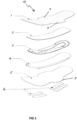
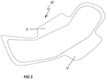
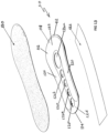
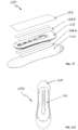
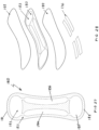
- FIGS 1 and 2 present a first embodiment of a winged version of cooling pad assembly in exploded and assembled view.
- FIG 1 conveys the assembly and layers of the construction.
- FIG 2 depicts the final constructed assembly of this embodiment.
- the assembly 10 depicted in FIG 1 is for a single use disposable pad assembly.
- the assembly 10 comprises a soft and thin absorption layer 1, intended for contact with skin, a thin absorption layer 2, optionally impregnated with one or more of witch hazel and lavender, to aid in wound healing, a cooling pad 3 to aid in relieving discomfort and help healing from swelling, perineal tears and episiotomies, a super absorbent core layer 4 to absorb fluids, an impermeable bottom layer 5 for increased protection from body fluids and adhesive strips 6 to keep pad in place.
- Layers 1 and 5 include wings 7.
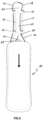
- Cooling pad 3 is described in more detail in connection with FIG 6 , below.
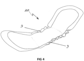
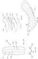
- FIGS 3 and 4 present a second embodiment of an elasticised version of cooling pad assembly 20 in exploded and assembled view.
- the assembly 20 depicted in FIG 3 is also for a single use disposable pad assembly.
- the assembly 20 comprises a soft and thin absorption layer 11, intended for contact with skin, a thin absorption layer 2, optionally impregnated with one or more of witch hazel and lavender, to aid in wound healing, a cooling pad 3 to aid in relieving discomfort and help healing from swelling, perineal tears and episiotomies, a super absorbent core layer 4 to absorb fluids, an impermeable bottom layer 15 for increased protection from body fluids and adhesive strips 6 to keep pad 20 in place.
- FIGS 3 and 4 are analogous to FIGS 1 and 2 , as is apparent. Most layers are the same, barring minor changes in shape to avoid a winged footprint. A notable difference is that impermeable bottom layer 5 features elasticised strip ribbing 8, to result in an assembled pad with elasticised sides as evident in FIG 4 , instead of the wings 7 in FIGS 1 and 2 . Elasticised sides 9 are designed to fit snugly to protect against leakage and provide a comfortable fit.
- FIGS 5 and 6 depicts in exploded view and detail components forming a variation to the first and second embodiments in which a "pocket" option is an alternative to the fully assembled construction outlined described and illustrated in connection with FIGS 1 to 4 .
- FIG 5 shows this alternative assembly 30.
- Layers 11, 4, 15 and 6 are essentially identical to the second embodiment described above in connection with FIGS 3 and 4 , omitting elasticised ribbing 8.
- Thin absorption layers 12a and 12b are fused together with an opening at the top to allow cooling pad 3 to be inserted later.
- Layer 12b covers and is bonded to bottom layers 4, 15 and 6. This alternative is illustrated as wingless but could have wings as in FIGS 1 and 2 or elasticised sides as in FIGS 3 and 4 .
- cooling pad 3 is inserted only if needed, and that cooling pad 3 can be supplied separately, instead of as part of an assembly.
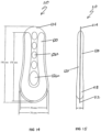
- cooling pad 3 has a periphery indicated at 13 and includes an inboard chamber 14 as well as chambers 16, 17, 18 and 19 around periphery 13.
- Each chamber 14, 16, 17, 18 and 19 contains a fluid for cooling, being a saline solution.
- Chambers 14, 16, 17, 18 and 19 are joined by web 21, which also contains apertures 22 to 25, for passage of body fluid to super absorbent core layer 4. Apertures 22 to 25, are located inboard of chambers 16, 17, 18 and 19.
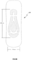
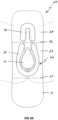
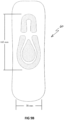
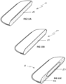
- FIGS 7A - 9A present three cooling pad assembly variations, with FIGS 7B , 8B and 9B presenting matching nominal dimensions for these three variations.
- cooling pad 3 is visible for purposes of illustration, although in fact cooling pad 3 would be covered by at least two layers.
- cooling pad 3 is shown in situ as part of an assembly 40, which is similar to assembly 10 (omitting wings 7) or assembly 20 (omitting elasticised sides 9).
- assembly 40 is similar to assembly 10 (omitting wings 7) or assembly 20 (omitting elasticised sides 9).
- web 21 is omitted
- assembly 40 is a schematic of the main areas of the perineum, showing location of assembly 40 in use. Details are described in relation to FIG 12 , below.
- assembly 40 has packaging folds 26 and 27, separating assembly 40 into three folding segments, anterior segment 28, middle segment 29 and posterior segment 31. Folds 26 and 27 are omitted from FIG 7B for simplicity.
- cooling pad 3 has horseshoe-shaped chamber 18 in anterior segment 28, elongate, parallel and spaced apart chambers 17 and 19 in middle segment 29 and teardrop-shaped chamber 14 and horseshoe-shaped 16 in posterior segment 31.
- Horseshoe-shaped chamber 16 faces horseshoe-shaped chamber 18.
- posterior segment 31 When worn, posterior segment 31 is placed abutting the anus and the middle segment 29 abuts the vulva - as depicted.
- FIGS 8A and 8B depict an assembly 50 with chambers located in anterior, middle and posterior segments (28, 29, 31) of the assembly, similar to assembly 40.
- the cooling pad 33 used is smaller and targeted specifically on areas for cooling, having inwardly facing horseshoe-shaped chamber 38 in anterior segment 28, and two elongate, S-curved or wishbone-shaped chambers 37 and 39 extending along the middle segment 29 and a terminating semi-circular chamber 36 in the posterior segment 31.
- the two elongate S-curved chambers 37, 39 frame a teardrop-shaped chamber 34 in middle segment 29.
- assembly 50 is placed so that chambers 38, 37 and 39 are next to the vulva and teardrop-shaped chamber 34 is next to the anus.
- Horseshoe-shaped chamber 38 in anterior segment 28 and semi-circular chamber 36 in posterior segment 31 could be interchanged, or substituted with near analogues as would be appreciated by those skilled in the art.
- FIGS 9A and 9B depict an assembly 60 having chambers only in anterior segment 28 and middle segment 29, reducing the number of segments having chambers. Cooling is also targeted specifically on the areas for cooling.
- cooling pad 43 has a horseshoe-shaped chamber 32, facing a larger horseshoe-shaped chamber 35 in middle segment 29, having centred therein a teardrop-shaped chamber 41.
- posterior segment 31 has no chamber. As worn, the vulva spans the anterior segment 28 and the middle segment 29, while the anus is over middle segment 29, towards the rear of horseshoe-shaped chamber 35.
- Cooling pad 43 is a contraction of cooling pad 3, collapsed to the anterior and middle segments 28, 29.
- the horseshoe-shaped chamber 16, 35 in the middle or posterior segment is larger than chamber 18, 32 in the anterior segment: the larger horseshoe-shaped chamber 16, 35 is about a third wider, and twice as long, as the smaller horseshoe-shaped chamber 18, 32.
- the larger horseshoe-shaped chambers 16, 35 and the S-curved chambers 37, 39 frame a central teardrop-shaped chamber 14, 34, 41, which is oriented to fill partly the internal space defined by these outer chambers. This provides a uniform cooling sensation across the area.
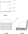
- FIGS 10A, 10B and 10C relate to aspects of packaging of the assemblies of some of the different embodiments described above. As is most clearly evident from FIGS 7A , 8A , 9A , the assemblies 40, 50, 60 are segmented into sections to permit ready folding into thirds, approximately among lines 26 and 27. This results in an approximately square-shaped packaging 70 as shown in FIGS 10A to 10C .
- FIG 10A depicts any of assemblies 40, 50, 60 after having been folded into thirds and packaged in an outer cover 44, heat sealed at 45 and 46 in known manner.
- cover 44 includes a temperature-sensitive device 47.
- Device 47 changes visual appearance to indicate when assembly 40, 50, 60 is sufficiently cold for use.
- Device 47 has suitable temperature-sensitive ink/s and/or coatings, such as those available from Chromatic Technologies Inc., of Colorado, United States of America.
- FIG 10B depicts a small stack 48 of packaged assemblies 40, 50, 60 as depicted in FIG 10A.
- FIG 10C illustrates in cross-sectional view segmentation of each such assembly when folded into the packaging 44 of FIGS 10A and 10B , per fold lines 26 and 27 indicated in FIGS 7A , 8A , 9A .
- FIGS 11A, 11B, 11C outline in cross-sectional view different constructional options for a chamber of a cooling pad of the invention, across different embodiments described herein. For convenience, the options are illustrated with regard to chamber 17 of cooling pad 3.
- FIG 11A depicts cooling option A: chamber 17 is filled with water or saline solution 45. This has the advantage of being a non-toxic affordable solution, which requires freezing before use.
- FIG 11B depicts cooling option B: chamber 17 is filled with a freezable gel, non-toxic 51. Gel 51 requires freezing before use and is reusable.
- FIG 11C depicts cooling option C: chamber 17 is filled with a urea 52 and in inner water - filled tube 53, which is a non-toxic instant cooling combination not requiring freezing.
- chamber 17 is manipulated to break inner water-filled tube 53, the resulting endothermic reaction with urea 52 causes cooling.
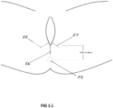
- FIG 12 shows schematically the main areas needed for cooling post birth. These include perineal tearing (1st, 2nd, 3rd and 4 th degree tears), possible episiotomy, indicated at 55, 56 and 57, and general swelling (not labelled).
- Anogenital distance is measured for women from the anus 58 to the base of the vagina and as indicated in FIG 12 is roughly between 22mm and 49mm, based on the AGD distances described in two studies of women of reproductive age [1, 2].
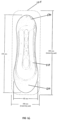
- cooling pad 110 has an anterior end 112 and a posterior end 114.
- Chamber 116 contains saline solution for cooling and has a first volume 118 at anterior end 112 and a pair of second volumes 120 between anterior end 112 and posterior end 114.
- first volume 118 is not partitioned from second volumes 120.
- Chamber 116 is approximately horseshoe-shaped.
- First volume 118 is located at the head 122 of the horseshoe, with second volumes 120 forming the legs.
- Web 124 is formed between the pair of second volumes 120 and has five apertures 126a to 126e to allow passage of body fluid.
- Cooling pad 110 may be used alone. However, in this embodiment, cooling pad 110 is part of an assembly, sandwiched between cover layer 130 and peel-off backing 132, and intended to be placed in a freezer or refrigerator prior to use.
- Cover layer 130 is adhered to cooling pad 110 by adhesive (not shown). As can be seen in Fig 13 , cover layer 130 is contoured to fit the body, as is cooling pad 110. Cover layer 130 may incorporate wings if desired.
- Adhesive (not shown) on the underside of cooling pad 110 can be used to adhere cooling pad 110 to underwear (not shown) by removing peel-off backing 132.
- chamber 116 contains 78 ml of saline solution.
- FIG 16 the assembly of FIGS 13 to 15 is shown superimposed on a maternity pad 134 (shown in dashed outline), with dimensions. Cooling pad 110 is adhered to maternity pad 134 after peel-off backing 132 is removed to expose adhesive (not shown).
- FIGS 17 and 18 illustrate a second form of assembly, 140.
- Assembly 140 has cooling pad 110, cover layer 130 and peel-off backing 132 which are the same as in the previous FIGS and which will not be described in detail again.
- adhesive strips 136 which are longer than cooling pad 110. Consequently, when assembly 140 is assembled as shown in FIG 18 , adhesive strips 136 extend beyond cooling pad 110 and are available to adhere assembly 140 to underwear or a maternity pad. It is to be noted that adhesive strips 136 are spaced apart so as not to impede body fluids travelling through cover layer 130 and apertures 126 in cooling pad 110.
- FIGS 19 and 20 illustrate a third form of assembly, 150.
- Assembly 150 has cooling pad 110, cover layer 130 and peel-off backing 132 which are the same as in the previous FIGS and which will not be described in detail again.
- adhesive strips 136a and 136b In assembly 150 there are adhesive strips 136a and 136b. Two adhesive strips 136a are located between cooling pad 110 and cover layer 130. Two adhesive strips 136b are located between cooling pad 110 and peel-off backing 132. In contrast to assembly 140, adhesive strips 136a, 136b are a little shorter than cooling pad 110.
- two adhesive strips 136a adhere cover layer 130 to cooling pad 110 and two adhesive strips 136b adhere to cooling pad 110.
- adhesive strips 136b are available to adhere assembly 150 to underwear or a maternity pad. As before, adhesive strips 136a, 136b are spaced apart so as not to impede body fluids travelling through cover layer 130 and apertures 126 in cooling pad 110.
- FIGS 21 to 23 illustrate how an assembly according to the present invention may be utilised. Reference is made to assembly 150, shown in FIGS 19 and 20 , but the method of use can apply to other embodiments.
- Assembly 150 is first chilled or frozen before use. When it is required, assembly 150 is removed from any packaging ( FIG 10A ). Peel-off backing layer 132 is removed, exposing adhesive strips 136b ( FIG 22 ). Assembly 150 is turned over so that adhesive strips 136b face downwards and positioned onto a maternity pad 134 or underwear 138 ( FIG 23 ), as desired.
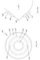
- Cooling pad 160 suitable for use as a mastitis pad is shown in FIG 24 .
- Cooling pad 160 two concentric chambers 161 and 162, joined at passages 163 and 164.
- passages 163 and 164 may be omitted.
- Chamber 161 lies along periphery 165.
- cooling pad 160 At the centre of cooling pad 160 is a single aperture 166, formed in web 167. Web 167 also joins chambers 161 and 162. Aperture 166 is inboard of chambers 161 and 162.
- aperture 166 is sized to accommodate a nipple 168 of breast 169.
- Each of the embodiments described above has included at least one aperture for allowing passage of body fluid, the aperture being located inboard of the one or more chambers.
- the embodiments below are of the second aspect : a cooling pad for perineum relief, the pad having an anterior end and a posterior end, and including one or more chambers, containing a fluid for cooling, located on a web.
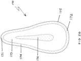
- FIG 26 shows in plan view cooling pad 170 having an anterior end 171 and a posterior end 172.
- cooling pad 170 has a single chamber 173, supported by web 174.
- Web 174 and chamber 173 are generally teardrop-shaped.
- the first or larger volume of chamber 173 is located near posterior end 172.
- Chamber 173 is located close to periphery 175 and travels around it.
- Chamber 173 encloses part of web 174, as shown.
- Cooling pad 170 may be provided with a soft and thin absorption layer 11, like that in FIG 3 but teardrop-shaped. Cooling pad 170 may also have adhesive strips as described above to enable attachment to clothing. Cooling pad 170 may be used to alleviate pain or discomfort in the perineum caused by cycling.
- Cooling pad 180 has an anterior end 181 and a posterior end 182, being of the same shape as anterior end 181.
- cooling pad 180 has a four linked chambers 183, 184, 185 and 186, supported by web 187, a non-woven fabric.
- the chambers 183, 184, 185 and 186 are made of plastic and filled with saline solution.
- cooling pad 180 is provided in an assembly having a top layer 188 being a non-woven fabric bonded to plastic, an under layer 189 of the same materials and four adhesive strips 176 for attaching the assembly to clothing.
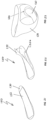
- Cooling pad 190 has three parallel chambers 191, 192 and 193 located on web 194. As illustrated in FIG 30 , the three parallel chambers 191, 192 and 193 allow pad 190 to contour to body shape in use, as indicated by the arrows.
- Cooling pad 190 can be inserted into an assembly as shown in FIGS 31 and 32 , in a similar way to the embodiment in FIG 6 .
- the assembly has an upper non-woven fabric layer 195, and a lower non-woven fabric layer 196 with elasticised strips 197.
- Layer 195 is bonded to layer 196, as shown by dotted line 198, leaving an opening 199 ( FIG 32 ) through which cooling pad 190 is inserted after it has been chilled or frozen to the desired temperature.
- Adhesive strips 176 can be used to attach the assembly to clothing.
- Elasticised strips 197 enable the sides of the assembly to fit snugly, as shown in FIG 32 . Cooling pad 190 may be reused, while the remainder of the assembly may be discarded after use.
- the cooling pads of the invention may be made of any suitable materials.
- Preferred materials are nylon or polyethylene for the plastic base layer and Fixomull (trade mark) or similar material for the soft upper layer, known for manufacture of personal care and wound care products.
- the preferred Fixomull product is available as Fixomull Stretch from, for example, BSN Medical, of Mount Waverley, Victoria, Australia.
- Fixomull Stretch is a hypoallergenic, porous, adhesive, non-woven tape, especially suitable for use on frequently mobile and highly contoured parts of the body. It is made from a white, stretchable, non-woven polyester dressing sheet coated with skin-friendly polyacrylate adhesive on quick-release backing paper.
- top layer 130 may be made from Fixomull Stretch and adhered to cooling pad 110, using the polyacrylate adhesive.
- bonding may take place by lamination, using heat sealing. Chambers may be filled with cooling fluid while the chambers are undergoing sealing.
- a preferred cooling fluid is saline solution, a hypotonic 7% salt solution. It is preferred that each chamber is of maximum volume 70 to 80 ml. A preservative or anti-bacterial may be included for longer shelf life, as may a dye.
- the cooling pad of the invention may be cooled to - 4 degrees Celsius without freezing.
- the cooling pad if cooled to - 4 degrees Celsius, is capable of providing relief in the range - 4 degrees to +4 degrees Celsius, for at least 30 minutes.
Landscapes
- Health & Medical Sciences (AREA)
- General Health & Medical Sciences (AREA)
- Veterinary Medicine (AREA)
- Biomedical Technology (AREA)
- Heart & Thoracic Surgery (AREA)
- Vascular Medicine (AREA)
- Life Sciences & Earth Sciences (AREA)
- Engineering & Computer Science (AREA)
- Animal Behavior & Ethology (AREA)
- Public Health (AREA)
- Epidemiology (AREA)
- Physics & Mathematics (AREA)
- Thermal Sciences (AREA)
- Chemical & Material Sciences (AREA)
- Chemical Kinetics & Catalysis (AREA)
- General Chemical & Material Sciences (AREA)
- Thermotherapy And Cooling Therapy Devices (AREA)
Description
- The invention relates to a cooling pad that in various embodiments may provide relief to the perineum after childbirth.
- After vaginal birth, the vaginal and perineal region can be very sore, swollen and tender. The discomfort can be significant as a consequence of acute tissue trauma.
- Current practice is to use ice blocks, sometimes sheathed in rubber, as a makeshift means to provide relief. There is no satisfactory cooling device designed for treating a sore, swollen, chafed or tender perineum after vaginal birth.
-
US 2012/089106 (Komatsu ) discloses an absorbent article, typically a sanitary napkin, aimed at providing a cooling sensation to a wearer, while avoiding excessive stimulation causing discomfort to the wearer. In Komatsu, a refresher agent, which releases a cooling sensation when it contacts a liquid, is incorporated into the absorbent article. The refresher agent is concentrated outside a zone of the absorbent article which contacts the wearer's 'excretion unit', namely the vaginal area, the perineum and the anus. Komatsu specifically avoids providing relief to the vaginal and perineal region.US2017/079836 refers to a further document relevant for the present invention. - There is a need for an effective, inexpensive cooling pad which can provide relief in post-birth conditions such as those described above or which can at least provide a useful alternative.
- The present invention is defined by the appended claims.
- Preferred embodiments are disclosed in the dependent claims.
- When the web has a plurality of apertures, it is preferred that there are several apertures, such as five, and that the apertures are of a size to allow body fluids to flow through the cooling pad with no or little restriction. In one embodiment, each aperture is generally oval in shape, having a length of between 1.5 and 2.5 cm and a width of up to 1 cm. It is preferred that the apertures are located at spaced intervals, for example from the first chamber to the end of the second and third chambers and of differing sizes. In this embodiment, one or more apertures closer to the first chamber are preferably larger than apertures towards the end of the second and third chambers. The apertures may be graduated in size along the web.
- In the aspects of the invention, it is preferred that the chamber or chambers are at or near the periphery of the cooling pad. In embodiments with four or more chambers, the chambers together do not need to be continuous around the periphery or to travel around the whole periphery. However it is preferred that the chambers together travel around a substantial part of the periphery.
- The pad may have any desired shape. For example, the pad may be a generally elongated oval or may have a shape similar to a maternity pad. For this application, the pad may have a wider anterior end and a narrower posterior end.
- The cooling fluid may be any suitable fluid. In one preferred embodiment, the cooling fluid is a saline solution, which may contain an amount of innocuous dye to tint the solution to a desired colour, such as aqua. The saline solution may include an anti-bacterial to enhance shelf life. As other examples, the cooling fluid may be water, another non-toxic solution or a gel.
- The cooling fluid may be cooled in a freezer or refrigerator as required. Alternately, the cooling fluid may be of a type which does not require freezing: the fluid may comprise urea and an inner water-filled tube which, when broken, causes an endothermic reaction with the urea, resulting in cooling.
- Preferably, the chamber size and number and the type of cooling fluid are designed to provide cooling relief for up to about 30 minutes after extraction from a freezer or refrigerator. Once the cooling fluid has reached a temperature at which the pad is no longer effective in providing relief, the pad may be discarded.
- There may be a plurality of chambers segmented between at least two of front, middle and rear sections. In this embodiment, fold lines may delineate the sections. The chambers are preferably segmented between all three of the front, the middle and the rear sections. The chambers of the rear section are preferably shaped and oriented in a facing horseshoe configuration with the horseshoe chamber of
claim 1. It is preferred that the horseshoe-shaped chamber of the rear section is larger than the horseshoe-shaped chamber of the front section, and has a further discrete chamber (preferably teardrop-shaped) centred within. Conveniently, the cooling pad of the invention may be formed by heat-sealing two layers of suitable sheet plastic, forming the chamber and the web in one step. The cooling pad of the invention may be formed in any other suitable way. - The cooling pad of the invention may be used alone, or it may be inserted into a suitable pocket for use. In another embodiment, the cooling pad of the invention may be combined with one or more layers in an assembly, to add comfort or to enable adhesion to clothing or a pad, for example.
- For instance, a cover layer may be placed over and adhered to the cooling pad, to provide an interface between the cooling pad and the relevant part of the perineum or other body part. The cover layer should allow body fluid to flow through in an appropriate application. The cover layer may be contoured to fit the body of the user. The cover layer may be impregnated with botanical or other products to aid healing or to provide a pleasing fragrance. If desired, the cover layer may incorporate wings with adhesive on one side, for adhering the cooling pad and cover to a garment.
- The cooling pad of the invention may include one or more adhesive strips to enable the cooling pad to be adhered to the body, to underwear or to a pad for absorbing body fluid. A peel-off backing may protect the adhesive until the cooling pad is ready for use. The adhesive strips may be located in any desired position on the cooling pad, but preferably under the cooling pad in use.
- The cooling pad of the invention in its various aspects may have on it or on its packaging a temperature-sensitive device printed or embedded thereon. Such a device can indicate when the cooling pad of the invention is sufficiently cool to be ready for use.
- The invention will now be described in relation to non-limiting embodiments, in conjunction with the accompanying
figures 1-23 (The embodiments offigures 24-32 fall outside the scope of the present claims) in which: -
FIG 1 is an exploded view of components of a cooling pad assembly according to a first embodiment of the present invention, which is packaged as a winged pad in assembled form; -
FIG 2 is a perspective view of an assembled winged pad housing the components ofFIG 1 ; -
FIG 3 is an exploded view of components of a cooling pad assembly according to a second embodiment of the present invention, which is packaged as an elasticised pad in assembled form; -
FIG 4 is a perspective view of an assembled elasticised pad housing the components ofFIG 3 ; -
FIG 5 is an exploded view of components of a cooling pad assembly according to a third embodiment of the present invention, which is a variation of the first embodiment; -
FIG 6 is a plan view of a cooling pad assembly ofFIG 5 ; -
FIGS 7 to 9 are schematic representations of respective variations in cooling pad design, and able to be used with first, second and first embodiments, of cooling pad assembly, overlayed with anatomical and nominal dimensional data; -
FIGS 10A to 10C are schematic representations of packaging forms for the embodiments depicted in connection withFIGS 1 to 9 ; -
FIGS 11A to 11C are schematic representations of cooling pack formats that may be used in connection with the embodiments depicted in connection withFIGS 1 to 9 ; -
FIG 12 illustrates the main areas of the perineum needing alleviation of pain or discomfort after vaginal delivery; -
FIG 13 is an exploded perspective view of components of a cooling pad assembly according to a further embodiment of the present invention, which includes a cover layer and a peel-off backing in an assembly; -
FIG 14 is a plan view from above of the cooling pad included inFIG 13 ; -
FIG 15 is a side view of the cooling pad shown inFIG 14 ; -
FIG 16 is a plan view of the assembly ofFIG 13 , superimposed upon a maternity pad; -
FIG 17 is a perspective exploded view of another embodiment of a cooling pad assembly where adhesive strips are located on the cover layer; -
FIG 18 is a plan view from below of the assembly ofFIG 17 ; -
FIG 19 is a perspective exploded view of a further embodiment of a cooling pad assembly where adhesive strips are located on both sides of the cooling pad; -
FIG 20 is a plan view from below of the assembly ofFIG 19 ; -
FIGS 21 to 23 are representations of an embodiment of a method of use of the cooling pad of the invention; -
FIG 24 shows a plan view of a mastitis pad; -
FIG 25 is a side elevation cross-sectional schematic view of the pad ofFIG 24 ; -
FIG 26 is a plan view of an embodiment of a cycle pad; -
FIG 27 is a plan view of another embodiment of cycle pad; -
FIG 28 is an exploded view of the cycle pad ofFIG 27 in an assembly; -
FIG 29 is a plan view of an embodiment of a prostate or vasectomy pad; -
FIG 30 is a side view of the embodiment ofFigure 29 ; -
FIG 31 is an exploded view of the prostate pad ofFIG 29 inserted into an assembly; and -
FIG 32 shows the assembly ofFIG 31 . - Each of the examples shown in
Figures 24 to 32 inclusive are shown for illustrative purposes only and do not form part of the invention as claimed. - Several embodiments are presented herein, some of which have variant constructions. None is intended to be limiting on the scope of the invention which is defined by the appended claims.
-
FIGS 1 and2 present a first embodiment of a winged version of cooling pad assembly in exploded and assembled view.FIG 1 conveys the assembly and layers of the construction.FIG 2 depicts the final constructed assembly of this embodiment. - The
assembly 10 depicted inFIG 1 is for a single use disposable pad assembly. Theassembly 10 comprises a soft andthin absorption layer 1, intended for contact with skin, athin absorption layer 2, optionally impregnated with one or more of witch hazel and lavender, to aid in wound healing, acooling pad 3 to aid in relieving discomfort and help healing from swelling, perineal tears and episiotomies, a superabsorbent core layer 4 to absorb fluids, an impermeablebottom layer 5 for increased protection from body fluids andadhesive strips 6 to keep pad in place. -
Layers wings 7. -
Cooling pad 3 is described in more detail in connection withFIG 6 , below. -
FIGS 3 and4 present a second embodiment of an elasticised version ofcooling pad assembly 20 in exploded and assembled view. - Items being the same as in
FIGS 1 and2 carry the same labels. - The
assembly 20 depicted inFIG 3 is also for a single use disposable pad assembly. Theassembly 20 comprises a soft andthin absorption layer 11, intended for contact with skin, athin absorption layer 2, optionally impregnated with one or more of witch hazel and lavender, to aid in wound healing, acooling pad 3 to aid in relieving discomfort and help healing from swelling, perineal tears and episiotomies, a superabsorbent core layer 4 to absorb fluids, an impermeablebottom layer 15 for increased protection from body fluids andadhesive strips 6 to keeppad 20 in place. -
FIGS 3 and4 are analogous toFIGS 1 and2 , as is apparent. Most layers are the same, barring minor changes in shape to avoid a winged footprint. A notable difference is that impermeablebottom layer 5 features elasticisedstrip ribbing 8, to result in an assembled pad with elasticised sides as evident inFIG 4 , instead of thewings 7 inFIGS 1 and2 . Elasticised sides 9 are designed to fit snugly to protect against leakage and provide a comfortable fit. -
FIGS 5 and6 depicts in exploded view and detail components forming a variation to the first and second embodiments in which a "pocket" option is an alternative to the fully assembled construction outlined described and illustrated in connection withFIGS 1 to 4 . -
FIG 5 shows thisalternative assembly 30.Layers FIGS 3 and4 , omittingelasticised ribbing 8. -
Thin absorption layers cooling pad 3 to be inserted later.Layer 12b covers and is bonded tobottom layers FIGS 1 and2 or elasticised sides as inFIGS 3 and4 . - The benefits of this alternative include that
cooling pad 3 is inserted only if needed, and thatcooling pad 3 can be supplied separately, instead of as part of an assembly. - As can be seen in
FIG 6 ,cooling pad 3 has a periphery indicated at 13 and includes aninboard chamber 14 as well aschambers periphery 13. Eachchamber -
Chambers web 21, which also containsapertures 22 to 25, for passage of body fluid to superabsorbent core layer 4.Apertures 22 to 25, are located inboard ofchambers -
FIGS 7A - 9A present three cooling pad assembly variations, withFIGS 7B ,8B and9B presenting matching nominal dimensions for these three variations. In each ofFIGS 7 to 9 ,cooling pad 3 is visible for purposes of illustration, although infact cooling pad 3 would be covered by at least two layers. - In
FIG 7A , coolingpad 3 is shown in situ as part of anassembly 40, which is similar to assembly 10 (omitting wings 7) or assembly 20 (omitting elasticised sides 9). For simplicity,web 21 is omitted Superimposed onassembly 40 is a schematic of the main areas of the perineum, showing location ofassembly 40 in use. Details are described in relation toFIG 12 , below. - As seen in
FIG 7A ,assembly 40 has packaging folds 26 and 27, separatingassembly 40 into three folding segments,anterior segment 28,middle segment 29 andposterior segment 31.Folds FIG 7B for simplicity. - In the embodiment of
FIGS 7A and7B ,cooling pad 3 has horseshoe-shapedchamber 18 inanterior segment 28, elongate, parallel and spaced apartchambers middle segment 29 and teardrop-shapedchamber 14 and horseshoe-shaped 16 inposterior segment 31. Horseshoe-shapedchamber 16 faces horseshoe-shapedchamber 18. - When worn,
posterior segment 31 is placed abutting the anus and themiddle segment 29 abuts the vulva - as depicted. -
FIGS 8A and8B depict anassembly 50 with chambers located in anterior, middle and posterior segments (28, 29, 31) of the assembly, similar toassembly 40. However, thecooling pad 33 used is smaller and targeted specifically on areas for cooling, having inwardly facing horseshoe-shapedchamber 38 inanterior segment 28, and two elongate, S-curved or wishbone-shapedchambers middle segment 29 and a terminatingsemi-circular chamber 36 in theposterior segment 31. The two elongate S-curved chambers chamber 34 inmiddle segment 29. In use,assembly 50 is placed so thatchambers chamber 34 is next to the anus. - Horseshoe-shaped
chamber 38 inanterior segment 28 andsemi-circular chamber 36 inposterior segment 31 could be interchanged, or substituted with near analogues as would be appreciated by those skilled in the art. -
FIGS 9A and9B depict anassembly 60 having chambers only inanterior segment 28 andmiddle segment 29, reducing the number of segments having chambers. Cooling is also targeted specifically on the areas for cooling. Inanterior segment 28cooling pad 43 has a horseshoe-shapedchamber 32, facing a larger horseshoe-shapedchamber 35 inmiddle segment 29, having centred therein a teardrop-shapedchamber 41. As is evident,posterior segment 31 has no chamber. As worn, the vulva spans theanterior segment 28 and themiddle segment 29, while the anus is overmiddle segment 29, towards the rear of horseshoe-shapedchamber 35. - Cooling
pad 43 is a contraction ofcooling pad 3, collapsed to the anterior andmiddle segments cooling pads chamber chamber chamber chamber - The larger horseshoe-shaped
chambers curved chambers chamber -
FIGS 10A, 10B and 10C relate to aspects of packaging of the assemblies of some of the different embodiments described above. As is most clearly evident fromFIGS 7A ,8A ,9A , theassemblies lines packaging 70 as shown inFIGS 10A to 10C . -
FIG 10A depicts any ofassemblies outer cover 44, heat sealed at 45 and 46 in known manner. Included oncover 44 is a temperature-sensitive device 47.Device 47 changes visual appearance to indicate whenassembly Device 47 has suitable temperature-sensitive ink/s and/or coatings, such as those available from Chromatic Technologies Inc., of Colorado, United States of America. -
FIG 10B depicts asmall stack 48 of packagedassemblies FIG 10A. FIG 10C illustrates in cross-sectional view segmentation of each such assembly when folded into thepackaging 44 ofFIGS 10A and 10B , perfold lines FIGS 7A ,8A ,9A . -
FIGS 11A, 11B, 11C outline in cross-sectional view different constructional options for a chamber of a cooling pad of the invention, across different embodiments described herein. For convenience, the options are illustrated with regard tochamber 17 ofcooling pad 3. -
FIG 11A depicts cooling option A:chamber 17 is filled with water orsaline solution 45. This has the advantage of being a non-toxic affordable solution, which requires freezing before use. -
FIG 11B depicts cooling option B:chamber 17 is filled with a freezable gel, non-toxic 51.Gel 51 requires freezing before use and is reusable. -
FIG 11C depicts cooling option C:chamber 17 is filled with aurea 52 and in inner water - filledtube 53, which is a non-toxic instant cooling combination not requiring freezing. Whenchamber 17 is manipulated to break inner water-filledtube 53, the resulting endothermic reaction withurea 52 causes cooling. - As will be appreciated, each of these options offers its own advantages and compromises.
-
FIG 12 shows schematically the main areas needed for cooling post birth. These include perineal tearing (1st, 2nd, 3rd and 4th degree tears), possible episiotomy, indicated at 55, 56 and 57, and general swelling (not labelled). - Anogenital distance (AGD) is measured for women from the
anus 58 to the base of the vagina and as indicated inFIG 12 is roughly between 22mm and 49mm, based on the AGD distances described in two studies of women of reproductive age [1, 2]. - In order to adequately cover the areas needed for as many women as possible, an average anogenital distance of 40mm was used for the cooling pad designs described above.
- Referring now to
Fig 13 ,cooling pad 110 has ananterior end 112 and aposterior end 114.Chamber 116 contains saline solution for cooling and has afirst volume 118 atanterior end 112 and a pair ofsecond volumes 120 betweenanterior end 112 andposterior end 114. In this embodiment,first volume 118 is not partitioned fromsecond volumes 120.Chamber 116 is approximately horseshoe-shaped.First volume 118 is located at thehead 122 of the horseshoe, withsecond volumes 120 forming the legs. -
Web 124 is formed between the pair ofsecond volumes 120 and has fiveapertures 126a to 126e to allow passage of body fluid. -
Cooling pad 110 may be used alone. However, in this embodiment, coolingpad 110 is part of an assembly, sandwiched betweencover layer 130 and peel-off backing 132, and intended to be placed in a freezer or refrigerator prior to use. -
Cover layer 130 is adhered tocooling pad 110 by adhesive (not shown). As can be seen inFig 13 ,cover layer 130 is contoured to fit the body, as is coolingpad 110.Cover layer 130 may incorporate wings if desired. - Adhesive (not shown) on the underside of
cooling pad 110 can be used to adherecooling pad 110 to underwear (not shown) by removing peel-off backing 132. - Turning now to
FIGS 14 and 15 , dimensions of an exemplary version ofcooling pad 110 are set out. In this embodiment,chamber 116 contains 78 ml of saline solution. - In
FIG 16 , the assembly ofFIGS 13 to 15 is shown superimposed on a maternity pad 134 (shown in dashed outline), with dimensions.Cooling pad 110 is adhered tomaternity pad 134 after peel-off backing 132 is removed to expose adhesive (not shown). -
FIGS 17 and 18 illustrate a second form of assembly, 140. The same labels are used to denote the same or equivalent components.Assembly 140 has coolingpad 110,cover layer 130 and peel-off backing 132 which are the same as in the previous FIGS and which will not be described in detail again. Inassembly 140 there areadhesive strips 136 which are longer than coolingpad 110. Consequently, whenassembly 140 is assembled as shown inFIG 18 ,adhesive strips 136 extend beyondcooling pad 110 and are available to adhereassembly 140 to underwear or a maternity pad. It is to be noted thatadhesive strips 136 are spaced apart so as not to impede body fluids travelling throughcover layer 130 and apertures 126 incooling pad 110. -
FIGS 19 and 20 illustrate a third form of assembly, 150. The same labels are used to denote the same or equivalent components.Assembly 150 has coolingpad 110,cover layer 130 and peel-off backing 132 which are the same as in the previous FIGS and which will not be described in detail again. Inassembly 150 there are adhesive strips 136a and 136b. Two adhesive strips 136a are located betweencooling pad 110 andcover layer 130. Two adhesive strips 136b are located betweencooling pad 110 and peel-off backing 132. In contrast toassembly 140, adhesive strips 136a, 136b are a little shorter than coolingpad 110. Whenassembly 150 is assembled as shown inFIG 20 , two adhesive strips 136a adherecover layer 130 tocooling pad 110 and two adhesive strips 136b adhere tocooling pad 110. When backinglayer 132 is peeled off, adhesive strips 136b are available to adhereassembly 150 to underwear or a maternity pad. As before, adhesive strips 136a, 136b are spaced apart so as not to impede body fluids travelling throughcover layer 130 and apertures 126 incooling pad 110. -
FIGS 21 to 23 illustrate how an assembly according to the present invention may be utilised. Reference is made toassembly 150, shown inFIGS 19 and 20 , but the method of use can apply to other embodiments. -
Assembly 150 is first chilled or frozen before use. When it is required,assembly 150 is removed from any packaging (FIG 10A ). Peel-off backing layer 132 is removed, exposing adhesive strips 136b (FIG 22 ).Assembly 150 is turned over so that adhesive strips 136b face downwards and positioned onto amaternity pad 134 or underwear 138 (FIG 23 ), as desired. - An embodiment of a
cooling pad 160 suitable for use as a mastitis pad is shown inFIG 24 .Cooling pad 160 twoconcentric chambers passages passages Chamber 161 lies alongperiphery 165. - At the centre of
cooling pad 160 is asingle aperture 166, formed inweb 167.Web 167 also joinschambers Aperture 166 is inboard ofchambers - As may be seen from the schematic cross-sectional view in
Figure 25 ,aperture 166 is sized to accommodate anipple 168 ofbreast 169. - Each of the embodiments described above has included at least one aperture for allowing passage of body fluid, the aperture being located inboard of the one or more chambers. The embodiments below are of the second aspect : a cooling pad for perineum relief, the pad having an anterior end and a posterior end, and including one or more chambers, containing a fluid for cooling, located on a web.
-
FIG 26 shows in planview cooling pad 170 having ananterior end 171 and aposterior end 172. In this embodiment, coolingpad 170 has asingle chamber 173, supported byweb 174.Web 174 andchamber 173 are generally teardrop-shaped. The first or larger volume ofchamber 173 is located nearposterior end 172.Chamber 173 is located close toperiphery 175 and travels around it.Chamber 173 encloses part ofweb 174, as shown.Cooling pad 170 may be provided with a soft andthin absorption layer 11, like that inFIG 3 but teardrop-shaped.Cooling pad 170 may also have adhesive strips as described above to enable attachment to clothing.Cooling pad 170 may be used to alleviate pain or discomfort in the perineum caused by cycling. - A second embodiment of a cycle pad is shown in
FIGS 27 and 28 .Cooling pad 180 has ananterior end 181 and aposterior end 182, being of the same shape asanterior end 181. In this embodiment, coolingpad 180 has a four linkedchambers web 187, a non-woven fabric. Thechambers - As shown in
FIG 28 ,cooling pad 180 is provided in an assembly having atop layer 188 being a non-woven fabric bonded to plastic, an underlayer 189 of the same materials and fouradhesive strips 176 for attaching the assembly to clothing. - The embodiment in
FIGS 29 to 31 is suitable for use for alleviating pain or discomfort in the perineum following vasectomy or prostate invasion.Cooling pad 190 has threeparallel chambers web 194. As illustrated inFIG 30 , the threeparallel chambers pad 190 to contour to body shape in use, as indicated by the arrows. -
Cooling pad 190 can be inserted into an assembly as shown inFIGS 31 and 32 , in a similar way to the embodiment inFIG 6 . The assembly has an uppernon-woven fabric layer 195, and a lowernon-woven fabric layer 196 withelasticised strips 197.Layer 195 is bonded to layer 196, as shown by dottedline 198, leaving an opening 199 (FIG 32 ) through whichcooling pad 190 is inserted after it has been chilled or frozen to the desired temperature. Adhesive strips 176 can be used to attach the assembly to clothing. - Elasticised strips 197 enable the sides of the assembly to fit snugly, as shown in
FIG 32 .Cooling pad 190 may be reused, while the remainder of the assembly may be discarded after use. - The cooling pads of the invention may be made of any suitable materials. Preferred materials are nylon or polyethylene for the plastic base layer and Fixomull (trade mark) or similar material for the soft upper layer, known for manufacture of personal care and wound care products. The preferred Fixomull product is available as Fixomull Stretch from, for example, BSN Medical, of Mount Waverley, Victoria, Australia. Fixomull Stretch is a hypoallergenic, porous, adhesive, non-woven tape, especially suitable for use on frequently mobile and highly contoured parts of the body. It is made from a white, stretchable, non-woven polyester dressing sheet coated with skin-friendly polyacrylate adhesive on quick-release backing paper. In the embodiment in
FIG 13 , for example,top layer 130 may be made from Fixomull Stretch and adhered tocooling pad 110, using the polyacrylate adhesive. - Where required, bonding may take place by lamination, using heat sealing. Chambers may be filled with cooling fluid while the chambers are undergoing sealing.
- A preferred cooling fluid is saline solution, a hypotonic 7% salt solution. It is preferred that each chamber is of
maximum volume 70 to 80 ml. A preservative or anti-bacterial may be included for longer shelf life, as may a dye. - Using a hypertonic 7% saline solution, the cooling pad of the invention may be cooled to - 4 degrees Celsius without freezing. In suitable embodiments, the cooling pad, if cooled to - 4 degrees Celsius, is capable of providing relief in the range - 4 degrees to +4 degrees Celsius, for at least 30 minutes.
- It will be appreciated that the embodiments of the invention described above are not intended to be limiting on the scope of the invention which is defined by the claims below.
Claims (10)
- A cooling pad (3; 33; 43; 110) for a female perineal region, for alleviation of pain or discomfort, the pad (3; 33; 43; 110) including:- an anterior end (112) and a posterior end (114);- one or more chambers (17, 18, 19; 37, 38, 39; 32; 116), containing a fluid for cooling, the chamber, or a plurality of the chambers together, forming a head and two legs in an approximately horseshoe configuration, with a first chamber (18; 38; 32; 116) at least located at the head of the horseshoe;
and- a web (21; 124) joining and extending between the head and legs of the horseshoe;
wherein the first chamber (18; 38; 32; 116) located at the head of the horseshoe is at the anterior end (112); and- at least one aperture (22, 23, 24, 25; 126, 126a, 126b, 126c, 126d, 126e) is formed in the web (21; 124) and located in an area between the head of the horseshoe and the two legs, the aperture (22, 23, 24, 25; 126, 126a, 126b, 126c, 126d, 126e) being adapted to allow passage of body fluid through the pad (3; 33; 43; 110), the at least one aperture having a boundary surrounded by the web. - The cooling pad (3; 33; 43; 110) of claim 1, wherein the web (21; 124) has a plurality of the apertures (22, 23, 24, 25; 126, 126a, 126b, 126c, 126d, 126e) located in the area.
- The cooling pad (3; 33; 43; 110) of claim 2, wherein the apertures (22, 23, 24, 25; 126, 126a, 126b, 126c, 126d, 126e) are of different sizes.
- The cooling pad (3; 33) of any one of claims 1 to 3, wherein the first chamber (18; 38) is partitioned from a second and a third chamber (17, 19; 37, 39) forming the legs of the horseshoe configuration.
- The cooling pad (3; 33) of claim 4, which includes a fourth chamber (16; 36) having a volume of fluid for cooling, the third chamber (16; 36) being located at the posterior end (114) of the pad.
- The cooling pad (3; 33) of claim 5, which includes a fifth chamber (14; 34) having a volume of fluid for cooling, the fourth chamber (14; 34) being located posteriorly of the first chamber (18; 38).
- The cooling pad (3; 33; 43; 110) of any one of claims 1 to 6, wherein the cooling fluid is a saline solution, adapted for freezing.
- The cooling pad (3; 33; 43; 110) of any one of claims 1 to 7, when included in an assembly (10; 20; 40; 50; 60; 140; 150) together with a cover sheet (1; 11; 130).
- The cooling pad (3; 33; 43; 110) of any one of claims 1 to 8, when used with an absorbent pad (4; 134).
- A cooling assembly (10; 20; 40; 50; 60; 140; 150) containing the cooling pad (3; 33; 43; 110) of any one of claims 1 to 9, together with adhesive means (6; 136; 136a, 136b).
Applications Claiming Priority (3)
| Application Number | Priority Date | Filing Date | Title |
|---|---|---|---|
| AU2016905244A AU2016905244A0 (en) | 2016-12-19 | Therapeutic Cooling Pad | |
| AU2017903387A AU2017903387A0 (en) | 2017-08-22 | Therapeutic Cooling Pad | |
| PCT/AU2017/000283 WO2018112501A1 (en) | 2016-12-19 | 2017-12-19 | Cooling pad |
Publications (3)
| Publication Number | Publication Date |
|---|---|
| EP3554433A1 EP3554433A1 (en) | 2019-10-23 |
| EP3554433A4 EP3554433A4 (en) | 2020-07-29 |
| EP3554433B1 true EP3554433B1 (en) | 2024-10-16 |
Family
ID=62624058
Family Applications (1)
| Application Number | Title | Priority Date | Filing Date |
|---|---|---|---|
| EP17883660.7A Active EP3554433B1 (en) | 2016-12-19 | 2017-12-19 | Cooling pad |
Country Status (12)
| Country | Link |
|---|---|
| US (1) | US11957618B2 (en) |
| EP (1) | EP3554433B1 (en) |
| JP (1) | JP7127051B2 (en) |
| KR (1) | KR20190114973A (en) |
| CN (1) | CN110087592B (en) |
| AU (2) | AU2017379368A1 (en) |
| BR (1) | BR112019012513A2 (en) |
| CA (1) | CA3047418C (en) |
| ES (1) | ES3002657T3 (en) |
| IL (1) | IL267460A (en) |
| MX (1) | MX2019007199A (en) |
| WO (1) | WO2018112501A1 (en) |
Families Citing this family (7)
| Publication number | Priority date | Publication date | Assignee | Title |
|---|---|---|---|---|
| JP7278292B2 (en) * | 2019-03-06 | 2023-05-19 | ユニ・チャーム株式会社 | absorbent article |
| US11877916B2 (en) | 2019-05-03 | 2024-01-23 | Parkview Health | Perineal therapy pad |
| WO2021050931A1 (en) * | 2019-09-12 | 2021-03-18 | Lansinoh Laboratories, Inc. | Freezable pad for pain relief |
| DE202020101089U1 (en) * | 2020-02-07 | 2021-05-10 | Febromed Gmbh & Co. Kg | Cooling bandage |
| JP7723964B2 (en) * | 2021-09-09 | 2025-08-15 | イントロン・スペース株式会社 | Protective Materials |
| WO2025046413A1 (en) | 2023-08-25 | 2025-03-06 | Boehringer Ingelheim Vetmedica Gmbh | Ndv aiv vectors and uses thereof |
| GB2636086A (en) * | 2023-11-28 | 2025-06-11 | Padsocle Ltd | Dressing |
Citations (1)
| Publication number | Priority date | Publication date | Assignee | Title |
|---|---|---|---|---|
| US20170079836A1 (en) * | 2015-09-21 | 2017-03-23 | Theresa R. Mahon | Women's underwear with labial cooling |
Family Cites Families (38)
| Publication number | Priority date | Publication date | Assignee | Title |
|---|---|---|---|---|
| US4397315A (en) | 1981-09-16 | 1983-08-09 | The Kendall Company | Dressing with temperature pack |
| JPS6025240Y2 (en) * | 1983-09-09 | 1985-07-29 | 十條キンバリ−株式会社 | sanitary napkins |
| US5178139A (en) * | 1990-03-05 | 1993-01-12 | Stephen P. Angelillo | Absorbent pad and thermal pack |
| US5167655A (en) | 1991-04-29 | 1992-12-01 | Mccoy Kevin | Cold therapy panty |
| US5304215A (en) | 1992-12-21 | 1994-04-19 | Macwhinnie Virginia | Thermal heat pack for breast |
| CA2111628A1 (en) | 1992-12-21 | 1994-06-22 | Virginia Macwhinnie | Heat pack for thermal treatment of breast |
| US5395399A (en) | 1993-06-14 | 1995-03-07 | Sport Wrapz, Inc. | Thermal wrap for a body member |
| US5476490A (en) * | 1994-05-10 | 1995-12-19 | Medela, Inc. | Heating pad |
| US5679052A (en) * | 1995-07-12 | 1997-10-21 | Rucki; Lawrence A. | Adjustable breast pack |
| US5697962A (en) | 1995-09-29 | 1997-12-16 | Dura-Kold Corporation | Therapeutic wrap |
| US6582383B2 (en) * | 1999-08-10 | 2003-06-24 | Larry R. Horning | Bandage for application of therapeutic cold or heat treatments to injuries |
| JP2001299807A (en) | 2000-04-18 | 2001-10-30 | Ooshin Medical:Kk | External patch |
| US6916334B2 (en) * | 2003-09-26 | 2005-07-12 | Maternal Care, Inc. | Thermal pack for the female breast |
| AU2005269773B2 (en) | 2004-07-23 | 2008-01-31 | Femaceuticals, Llc | Mini pad for reducing inflammation of the vulva and method of making the same |
| US20160051404A1 (en) | 2006-10-05 | 2016-02-25 | Ramsey Joe Choucair | Cold Compress for Therapeutic Cooling |
| US20100114053A1 (en) * | 2007-01-17 | 2010-05-06 | Deborah Kay Mandeville | Birthpad |
| CN201046188Y (en) * | 2007-04-27 | 2008-04-16 | 王成亚 | Automatic cleaning comfortable sanitary napkin containing crust element fibre as well as protecting pad |
| BRPI0813202B8 (en) * | 2007-08-03 | 2021-06-22 | Kimberly Clark Co | absorbent feminine care article |
| JP5297784B2 (en) * | 2008-12-16 | 2013-09-25 | 花王株式会社 | Method for manufacturing absorbent article |
| AU2009333850A1 (en) * | 2008-12-17 | 2011-08-11 | Antonella F. Carlozzi | Feminine undergarment |
| CN201558228U (en) * | 2008-12-30 | 2010-08-25 | 王寰 | Multifunctional perineum kerf protecting pad |
| JP5465910B2 (en) | 2009-03-31 | 2014-04-09 | ユニ・チャーム株式会社 | Absorbent articles |
| CN101889920A (en) | 2009-05-19 | 2010-11-24 | 上海因坊特生物科技有限公司 | Cold compress pad for perineum |
| US10639189B2 (en) * | 2010-03-28 | 2020-05-05 | Kimberly Jo Cull | Treating conditions caused by abnormal growth of pathogens in body cavities |
| US8637430B2 (en) | 2010-04-23 | 2014-01-28 | The Procter & Gamble Company | Web substrate having activated color regions in topical additive regions |
| US20110314640A1 (en) | 2010-06-26 | 2011-12-29 | Reynolds Patrick M | Attachable Gel Strap Wrap and Method |
| US9572709B2 (en) * | 2010-08-24 | 2017-02-21 | Michelle Lynn FOGG | Feminine cooling pad |
| CN103260561B (en) * | 2010-12-22 | 2016-12-14 | 3M创新有限公司 | Dual-purpose binding agent binder |
| US20120259303A1 (en) * | 2011-04-11 | 2012-10-11 | Marcia Angela Carter | Disposable breast pad |
| AU2011101004B4 (en) | 2011-08-10 | 2012-06-07 | Lucina Holdings Pty Ltd | Cool Absorbent Pad |
| US20130116762A1 (en) | 2011-11-09 | 2013-05-09 | Ernest Lai | Oral surgery recovery mask |
| EP2806838B1 (en) | 2012-01-27 | 2021-10-06 | Golf Jox Inc. | Back support garment apparatus |
| CN202699427U (en) * | 2012-08-17 | 2013-01-30 | 天津市中科健新材料技术有限公司 | Cool and refreshing sanitary towel |
| US20140230831A1 (en) | 2013-02-20 | 2014-08-21 | LevElena Enterprises, Inc. | Three dimensional structural support for female pelvic organs in thong underwear |
| CN203539523U (en) * | 2013-09-18 | 2014-04-16 | 宁波市北仑区人民医院 | Perineum cold compression pad for female patients |
| US20150297396A1 (en) * | 2014-04-22 | 2015-10-22 | Rapid Aid Corp. | Method of manufacturing disposable cold pack and related disposable cold pack containing phosphate ammonium nitrate |
| CN204133689U (en) * | 2014-09-11 | 2015-02-04 | 李蕾 | A kind of pudendum cold-compress ice pad |
| CN106999322B (en) * | 2014-12-30 | 2018-09-21 | 金伯利-克拉克环球有限公司 | Absorbing products with the separable skin contact cover in part |
-
2017
- 2017-12-19 AU AU2017379368A patent/AU2017379368A1/en not_active Abandoned
- 2017-12-19 ES ES17883660T patent/ES3002657T3/en active Active
- 2017-12-19 WO PCT/AU2017/000283 patent/WO2018112501A1/en not_active Ceased
- 2017-12-19 BR BR112019012513-2A patent/BR112019012513A2/en not_active IP Right Cessation
- 2017-12-19 MX MX2019007199A patent/MX2019007199A/en unknown
- 2017-12-19 CN CN201780078742.8A patent/CN110087592B/en active Active
- 2017-12-19 EP EP17883660.7A patent/EP3554433B1/en active Active
- 2017-12-19 KR KR1020197021268A patent/KR20190114973A/en not_active Abandoned
- 2017-12-19 CA CA3047418A patent/CA3047418C/en active Active
- 2017-12-19 US US16/470,664 patent/US11957618B2/en active Active
- 2017-12-19 JP JP2019553598A patent/JP7127051B2/en active Active
-
2019
- 2019-06-18 IL IL267460A patent/IL267460A/en unknown
-
2023
- 2023-11-10 AU AU2023263557A patent/AU2023263557B2/en active Active
Patent Citations (1)
| Publication number | Priority date | Publication date | Assignee | Title |
|---|---|---|---|---|
| US20170079836A1 (en) * | 2015-09-21 | 2017-03-23 | Theresa R. Mahon | Women's underwear with labial cooling |
Also Published As
| Publication number | Publication date |
|---|---|
| EP3554433A1 (en) | 2019-10-23 |
| NZ755163A (en) | 2025-05-02 |
| IL267460A (en) | 2019-08-29 |
| CA3047418A1 (en) | 2018-06-28 |
| JP7127051B2 (en) | 2022-08-29 |
| US20200085614A1 (en) | 2020-03-19 |
| CN110087592B (en) | 2023-04-07 |
| KR20190114973A (en) | 2019-10-10 |
| MX2019007199A (en) | 2019-10-21 |
| AU2023263557A1 (en) | 2023-11-30 |
| AU2023263557B2 (en) | 2025-09-25 |
| US11957618B2 (en) | 2024-04-16 |
| EP3554433A4 (en) | 2020-07-29 |
| CA3047418C (en) | 2023-11-14 |
| ES3002657T3 (en) | 2025-03-07 |
| BR112019012513A2 (en) | 2019-11-19 |
| WO2018112501A1 (en) | 2018-06-28 |
| JP2020501860A (en) | 2020-01-23 |
| CN110087592A (en) | 2019-08-02 |
| AU2017379368A1 (en) | 2019-07-25 |
Similar Documents
| Publication | Publication Date | Title |
|---|---|---|
| CA3047418C (en) | Cooling pad | |
| US7559907B2 (en) | Temperature-controllable device | |
| US4243041A (en) | Cold-pack goggles | |
| US8937212B2 (en) | Feminine cooling pad | |
| US9962286B2 (en) | Women's underwear with labial cooling | |
| US9572709B2 (en) | Feminine cooling pad | |
| US7309275B1 (en) | Therapeutic brassiere incorporating thermal gel | |
| US20180263677A1 (en) | Adhesive liners for cryotherapy | |
| US11877916B2 (en) | Perineal therapy pad | |
| US20160030237A1 (en) | Therapeutic treatment pad | |
| US7275977B1 (en) | Therapeutic bra | |
| PL172903B1 (en) | Thermal bandage | |
| US20060081000A1 (en) | Non-slip ice bag device and method for using same to treat patients | |
| US20180221198A1 (en) | Women's underwear with removable labial cooling | |
| KR102628722B1 (en) | Fluid retention/retention pad | |
| US20120089212A1 (en) | Thermal Pad | |
| HK40006516A (en) | Cooling pad | |
| HK40006516B (en) | Cooling pad | |
| AU2011101004B4 (en) | Cool Absorbent Pad | |
| JP2000232989A (en) | Cooling and warming implement for human body section | |
| GB2501576A (en) | A pressure ring allowing aeration of a wound covered by a skin fold | |
| CN212015906U (en) | Hernia band with ice compress function | |
| US20160074551A1 (en) | Disposable absorbent pad | |
| JP3181594U (en) | Cooling and heating device |
Legal Events
| Date | Code | Title | Description |
|---|---|---|---|
| STAA | Information on the status of an ep patent application or granted ep patent |
Free format text: STATUS: THE INTERNATIONAL PUBLICATION HAS BEEN MADE |
|
| PUAI | Public reference made under article 153(3) epc to a published international application that has entered the european phase |
Free format text: ORIGINAL CODE: 0009012 |
|
| STAA | Information on the status of an ep patent application or granted ep patent |
Free format text: STATUS: REQUEST FOR EXAMINATION WAS MADE |
|
| 17P | Request for examination filed |
Effective date: 20190717 |
|
| AK | Designated contracting states |
Kind code of ref document: A1 Designated state(s): AL AT BE BG CH CY CZ DE DK EE ES FI FR GB GR HR HU IE IS IT LI LT LU LV MC MK MT NL NO PL PT RO RS SE SI SK SM TR |
|
| AX | Request for extension of the european patent |
Extension state: BA ME |
|
| DAV | Request for validation of the european patent (deleted) | ||
| DAX | Request for extension of the european patent (deleted) | ||
| A4 | Supplementary search report drawn up and despatched |
Effective date: 20200629 |
|
| RIC1 | Information provided on ipc code assigned before grant |
Ipc: A61F 7/10 20060101ALI20200623BHEP Ipc: A61F 13/15 20060101ALI20200623BHEP Ipc: A61F 7/02 20060101AFI20200623BHEP Ipc: A61F 13/472 20060101ALN20200623BHEP |
|
| P01 | Opt-out of the competence of the unified patent court (upc) registered |
Effective date: 20230530 |
|
| GRAP | Despatch of communication of intention to grant a patent |
Free format text: ORIGINAL CODE: EPIDOSNIGR1 |
|
| STAA | Information on the status of an ep patent application or granted ep patent |
Free format text: STATUS: GRANT OF PATENT IS INTENDED |
|
| RIC1 | Information provided on ipc code assigned before grant |
Ipc: A61F 13/472 20060101ALN20240426BHEP Ipc: A61F 7/10 20060101ALI20240426BHEP Ipc: A61F 13/15 20060101ALI20240426BHEP Ipc: A61F 7/02 20060101AFI20240426BHEP |
|
| INTG | Intention to grant announced |
Effective date: 20240514 |
|
| GRAS | Grant fee paid |
Free format text: ORIGINAL CODE: EPIDOSNIGR3 |
|
| GRAA | (expected) grant |
Free format text: ORIGINAL CODE: 0009210 |
|
| STAA | Information on the status of an ep patent application or granted ep patent |
Free format text: STATUS: THE PATENT HAS BEEN GRANTED |
|
| AK | Designated contracting states |
Kind code of ref document: B1 Designated state(s): AL AT BE BG CH CY CZ DE DK EE ES FI FR GB GR HR HU IE IS IT LI LT LU LV MC MK MT NL NO PL PT RO RS SE SI SK SM TR |
|
| REG | Reference to a national code |
Ref country code: GB Ref legal event code: FG4D |
|
| REG | Reference to a national code |
Ref country code: CH Ref legal event code: EP |
|
| REG | Reference to a national code |
Ref country code: IE Ref legal event code: FG4D |
|
| REG | Reference to a national code |
Ref country code: DE Ref legal event code: R096 Ref document number: 602017085582 Country of ref document: DE |
|
| REG | Reference to a national code |
Ref country code: NL Ref legal event code: FP |
|
| REG | Reference to a national code |
Ref country code: LT Ref legal event code: MG9D |
|
| REG | Reference to a national code |
Ref country code: ES Ref legal event code: FG2A Ref document number: 3002657 Country of ref document: ES Kind code of ref document: T3 Effective date: 20250307 |
|
| REG | Reference to a national code |
Ref country code: AT Ref legal event code: MK05 Ref document number: 1732341 Country of ref document: AT Kind code of ref document: T Effective date: 20241016 |
|
| PG25 | Lapsed in a contracting state [announced via postgrant information from national office to epo] |
Ref country code: PT Free format text: LAPSE BECAUSE OF FAILURE TO SUBMIT A TRANSLATION OF THE DESCRIPTION OR TO PAY THE FEE WITHIN THE PRESCRIBED TIME-LIMIT Effective date: 20250217 Ref country code: HR Free format text: LAPSE BECAUSE OF FAILURE TO SUBMIT A TRANSLATION OF THE DESCRIPTION OR TO PAY THE FEE WITHIN THE PRESCRIBED TIME-LIMIT Effective date: 20241016 Ref country code: IS Free format text: LAPSE BECAUSE OF FAILURE TO SUBMIT A TRANSLATION OF THE DESCRIPTION OR TO PAY THE FEE WITHIN THE PRESCRIBED TIME-LIMIT Effective date: 20250216 |
|
| PG25 | Lapsed in a contracting state [announced via postgrant information from national office to epo] |
Ref country code: FI Free format text: LAPSE BECAUSE OF FAILURE TO SUBMIT A TRANSLATION OF THE DESCRIPTION OR TO PAY THE FEE WITHIN THE PRESCRIBED TIME-LIMIT Effective date: 20241016 |
|
| PG25 | Lapsed in a contracting state [announced via postgrant information from national office to epo] |
Ref country code: BG Free format text: LAPSE BECAUSE OF FAILURE TO SUBMIT A TRANSLATION OF THE DESCRIPTION OR TO PAY THE FEE WITHIN THE PRESCRIBED TIME-LIMIT Effective date: 20241016 |
|
| PG25 | Lapsed in a contracting state [announced via postgrant information from national office to epo] |
Ref country code: NO Free format text: LAPSE BECAUSE OF FAILURE TO SUBMIT A TRANSLATION OF THE DESCRIPTION OR TO PAY THE FEE WITHIN THE PRESCRIBED TIME-LIMIT Effective date: 20250116 |
|
| PG25 | Lapsed in a contracting state [announced via postgrant information from national office to epo] |
Ref country code: AT Free format text: LAPSE BECAUSE OF FAILURE TO SUBMIT A TRANSLATION OF THE DESCRIPTION OR TO PAY THE FEE WITHIN THE PRESCRIBED TIME-LIMIT Effective date: 20241016 Ref country code: LV Free format text: LAPSE BECAUSE OF FAILURE TO SUBMIT A TRANSLATION OF THE DESCRIPTION OR TO PAY THE FEE WITHIN THE PRESCRIBED TIME-LIMIT Effective date: 20241016 Ref country code: GR Free format text: LAPSE BECAUSE OF FAILURE TO SUBMIT A TRANSLATION OF THE DESCRIPTION OR TO PAY THE FEE WITHIN THE PRESCRIBED TIME-LIMIT Effective date: 20250117 |
|
| PG25 | Lapsed in a contracting state [announced via postgrant information from national office to epo] |
Ref country code: PL Free format text: LAPSE BECAUSE OF FAILURE TO SUBMIT A TRANSLATION OF THE DESCRIPTION OR TO PAY THE FEE WITHIN THE PRESCRIBED TIME-LIMIT Effective date: 20241016 |
|
| PG25 | Lapsed in a contracting state [announced via postgrant information from national office to epo] |
Ref country code: RS Free format text: LAPSE BECAUSE OF FAILURE TO SUBMIT A TRANSLATION OF THE DESCRIPTION OR TO PAY THE FEE WITHIN THE PRESCRIBED TIME-LIMIT Effective date: 20250116 |
|
| PG25 | Lapsed in a contracting state [announced via postgrant information from national office to epo] |
Ref country code: SM Free format text: LAPSE BECAUSE OF FAILURE TO SUBMIT A TRANSLATION OF THE DESCRIPTION OR TO PAY THE FEE WITHIN THE PRESCRIBED TIME-LIMIT Effective date: 20241016 |
|
| PG25 | Lapsed in a contracting state [announced via postgrant information from national office to epo] |
Ref country code: MC Free format text: LAPSE BECAUSE OF FAILURE TO SUBMIT A TRANSLATION OF THE DESCRIPTION OR TO PAY THE FEE WITHIN THE PRESCRIBED TIME-LIMIT Effective date: 20241016 |
|
| PG25 | Lapsed in a contracting state [announced via postgrant information from national office to epo] |
Ref country code: DK Free format text: LAPSE BECAUSE OF FAILURE TO SUBMIT A TRANSLATION OF THE DESCRIPTION OR TO PAY THE FEE WITHIN THE PRESCRIBED TIME-LIMIT Effective date: 20241016 |
|
| REG | Reference to a national code |
Ref country code: DE Ref legal event code: R097 Ref document number: 602017085582 Country of ref document: DE |
|
| PG25 | Lapsed in a contracting state [announced via postgrant information from national office to epo] |
Ref country code: EE Free format text: LAPSE BECAUSE OF FAILURE TO SUBMIT A TRANSLATION OF THE DESCRIPTION OR TO PAY THE FEE WITHIN THE PRESCRIBED TIME-LIMIT Effective date: 20241016 |
|
| PG25 | Lapsed in a contracting state [announced via postgrant information from national office to epo] |
Ref country code: RO Free format text: LAPSE BECAUSE OF FAILURE TO SUBMIT A TRANSLATION OF THE DESCRIPTION OR TO PAY THE FEE WITHIN THE PRESCRIBED TIME-LIMIT Effective date: 20241016 |
|
| PG25 | Lapsed in a contracting state [announced via postgrant information from national office to epo] |
Ref country code: SK Free format text: LAPSE BECAUSE OF FAILURE TO SUBMIT A TRANSLATION OF THE DESCRIPTION OR TO PAY THE FEE WITHIN THE PRESCRIBED TIME-LIMIT Effective date: 20241016 |
|
| REG | Reference to a national code |
Ref country code: CH Ref legal event code: PL |
|
| PG25 | Lapsed in a contracting state [announced via postgrant information from national office to epo] |
Ref country code: LU Free format text: LAPSE BECAUSE OF NON-PAYMENT OF DUE FEES Effective date: 20241219 |
|
| PLBE | No opposition filed within time limit |
Free format text: ORIGINAL CODE: 0009261 |
|
| STAA | Information on the status of an ep patent application or granted ep patent |
Free format text: STATUS: NO OPPOSITION FILED WITHIN TIME LIMIT |
|
| PG25 | Lapsed in a contracting state [announced via postgrant information from national office to epo] |
Ref country code: SE Free format text: LAPSE BECAUSE OF FAILURE TO SUBMIT A TRANSLATION OF THE DESCRIPTION OR TO PAY THE FEE WITHIN THE PRESCRIBED TIME-LIMIT Effective date: 20241016 |
|
| 26N | No opposition filed |
Effective date: 20250717 |
|
| REG | Reference to a national code |
Ref country code: BE Ref legal event code: MM Effective date: 20241231 |
|
| PG25 | Lapsed in a contracting state [announced via postgrant information from national office to epo] |
Ref country code: BE Free format text: LAPSE BECAUSE OF NON-PAYMENT OF DUE FEES Effective date: 20241231 |
|
| PG25 | Lapsed in a contracting state [announced via postgrant information from national office to epo] |
Ref country code: CH Free format text: LAPSE BECAUSE OF NON-PAYMENT OF DUE FEES Effective date: 20241231 |
|
| PGFP | Annual fee paid to national office [announced via postgrant information from national office to epo] |
Ref country code: GB Payment date: 20251210 Year of fee payment: 9 |
|
| PGFP | Annual fee paid to national office [announced via postgrant information from national office to epo] |
Ref country code: FR Payment date: 20251218 Year of fee payment: 9 Ref country code: NL Payment date: 20251217 Year of fee payment: 9 |
|
| PGFP | Annual fee paid to national office [announced via postgrant information from national office to epo] |
Ref country code: CZ Payment date: 20251209 Year of fee payment: 9 Ref country code: IE Payment date: 20251218 Year of fee payment: 9 |
|
| PGFP | Annual fee paid to national office [announced via postgrant information from national office to epo] |
Ref country code: ES Payment date: 20260119 Year of fee payment: 9 |
|
| PGFP | Annual fee paid to national office [announced via postgrant information from national office to epo] |
Ref country code: DE Payment date: 20251222 Year of fee payment: 9 |
|
| PGFP | Annual fee paid to national office [announced via postgrant information from national office to epo] |
Ref country code: IT Payment date: 20251231 Year of fee payment: 9 |