EP3554339B1 - System zur medizinischen bildgebung - Google Patents
System zur medizinischen bildgebung Download PDFInfo
- Publication number
- EP3554339B1 EP3554339B1 EP17818612.8A EP17818612A EP3554339B1 EP 3554339 B1 EP3554339 B1 EP 3554339B1 EP 17818612 A EP17818612 A EP 17818612A EP 3554339 B1 EP3554339 B1 EP 3554339B1
- Authority
- EP
- European Patent Office
- Prior art keywords
- scattering parameters
- region
- interest
- imaging system
- frequencies
- Prior art date
- Legal status (The legal status is an assumption and is not a legal conclusion. Google has not performed a legal analysis and makes no representation as to the accuracy of the status listed.)
- Active
Links
Images



Classifications
-
- A—HUMAN NECESSITIES
- A61—MEDICAL OR VETERINARY SCIENCE; HYGIENE
- A61B—DIAGNOSIS; SURGERY; IDENTIFICATION
- A61B5/00—Measuring for diagnostic purposes; Identification of persons
- A61B5/05—Detecting, measuring or recording for diagnosis by means of electric currents or magnetic fields; Measuring using microwaves or radio waves
- A61B5/0507—Detecting, measuring or recording for diagnosis by means of electric currents or magnetic fields; Measuring using microwaves or radio waves using microwaves or terahertz waves
-
- A—HUMAN NECESSITIES
- A61—MEDICAL OR VETERINARY SCIENCE; HYGIENE
- A61B—DIAGNOSIS; SURGERY; IDENTIFICATION
- A61B5/00—Measuring for diagnostic purposes; Identification of persons
- A61B5/43—Detecting, measuring or recording for evaluating the reproductive systems
- A61B5/4306—Detecting, measuring or recording for evaluating the reproductive systems for evaluating the female reproductive systems, e.g. gynaecological evaluations
- A61B5/4312—Breast evaluation or disorder diagnosis
-
- A—HUMAN NECESSITIES
- A61—MEDICAL OR VETERINARY SCIENCE; HYGIENE
- A61B—DIAGNOSIS; SURGERY; IDENTIFICATION
- A61B5/00—Measuring for diagnostic purposes; Identification of persons
- A61B5/70—Means for positioning the patient in relation to the detecting, measuring or recording means
- A61B5/708—Breast positioning means
-
- A—HUMAN NECESSITIES
- A61—MEDICAL OR VETERINARY SCIENCE; HYGIENE
- A61B—DIAGNOSIS; SURGERY; IDENTIFICATION
- A61B5/00—Measuring for diagnostic purposes; Identification of persons
- A61B5/72—Signal processing specially adapted for physiological signals or for diagnostic purposes
- A61B5/7235—Details of waveform analysis
- A61B5/7264—Classification of physiological signals or data, e.g. using neural networks, statistical classifiers, expert systems or fuzzy systems
-
- A—HUMAN NECESSITIES
- A61—MEDICAL OR VETERINARY SCIENCE; HYGIENE
- A61B—DIAGNOSIS; SURGERY; IDENTIFICATION
- A61B2562/00—Details of sensors; Constructional details of sensor housings or probes; Accessories for sensors
- A61B2562/02—Details of sensors specially adapted for in-vivo measurements
- A61B2562/0228—Microwave sensors
-
- A—HUMAN NECESSITIES
- A61—MEDICAL OR VETERINARY SCIENCE; HYGIENE
- A61B—DIAGNOSIS; SURGERY; IDENTIFICATION
- A61B2562/00—Details of sensors; Constructional details of sensor housings or probes; Accessories for sensors
- A61B2562/04—Arrangements of multiple sensors of the same type
- A61B2562/046—Arrangements of multiple sensors of the same type in a matrix array
-
- G—PHYSICS
- G16—INFORMATION AND COMMUNICATION TECHNOLOGY [ICT] SPECIALLY ADAPTED FOR SPECIFIC APPLICATION FIELDS
- G16H—HEALTHCARE INFORMATICS, i.e. INFORMATION AND COMMUNICATION TECHNOLOGY [ICT] SPECIALLY ADAPTED FOR THE HANDLING OR PROCESSING OF MEDICAL OR HEALTHCARE DATA
- G16H50/00—ICT specially adapted for medical diagnosis, medical simulation or medical data mining; ICT specially adapted for detecting, monitoring or modelling epidemics or pandemics
- G16H50/20—ICT specially adapted for medical diagnosis, medical simulation or medical data mining; ICT specially adapted for detecting, monitoring or modelling epidemics or pandemics for computer-aided diagnosis, e.g. based on medical expert systems
Definitions
- the invention relates to a medical imaging system for tissue identification, in vivo.
- imaging techniques are known for examining the human body. Such imaging techniques may be used to interrogate tissues and organs in order to identify tissue. For example, X-ray (mammography), microwave imaging, ultrasound, MRI are all common imaging modalities. Such techniques are commonly used to examine breast tissue, but may also be used in other areas of the body, such as the liver, pancreas, prostate, thyroid, lungs, ovaries and lymph nodes. Known examples of medical imaging techniques are described in US 2016/106334 , US 2006/241409 and US 2012/190977 .
- a microwave imaging system comprising:
- the scattering ptest2arameters may be frequency domain scattering parameters. For example, a scattering parameter for a point (or region of interest) is determined for each frequency and may be considered to form a spectrum across the range of frequencies.
- the processor may classify the region of interest as malignant or benign.
- the processor may classify the region of interest based on an average magnitude value of the scattering parameters in the set of scattering parameters corresponding to the region of interest over a first frequency range and on an average magnitude value of the scattering parameters in the set of scattering parameters corresponding to the region of interest over a second frequency range.
- the processor may classify the region of interest based on a decision boundary dividing values for the first and second frequency ranges into at least two classes.
- the first and second frequency ranges may be non-adjacent.
- Analysing the change of the scattering parameters in the set of scattering parameters corresponding to the region of interest over the range of frequencies may comprise determining a change in permittivity with frequency based on the change of the scattering parameters in the set of scattering parameters over the range of frequencies; and the processor may be configured to classify the region of interest based on the determined change in permittivity with frequency.
- Analysing the change of the scattering parameters in the set of scattering parameters corresponding to the region of interest over the range of frequencies may comprise determining the static conductivity and/or the polarisation intensity of the region of interest, based on the change in scattering parameters in the set of scattering parameters over the range of frequencies; and the processor may be configured to classify the region of interest based on a predetermined correlation between tissue type and the static conductivity and/or the polarisation intensity.
- the processor may be configured to project the scattering parameters in the set of scattering parameters corresponding to the region of interest (e.g. the average scattering parameters for the first and second frequency ranges) to a predefined reference coordinate space; and the processor may be configured to classify the region of interest based on the position of the projected scattering parameters within the predefined reference coordinate space.
- the region of interest e.g. the average scattering parameters for the first and second frequency ranges
- the predefined reference coordinate space may comprise a plurality of axes, wherein each axis corresponds to a principal component of a set of reference data.
- the set of reference data may comprise a plurality of sets of scattering parameters obtained for respective sets of sample tissues of known tissue types.
- a plurality of sets of scattering parameters may have been obtained using the method of the invention for sample tissues of known tissue types.
- the microwave antenna array may be formed on a substrate, wherein the substrate is contoured or contourable to conform to the body part.
- the substrate may be hemispherical.
- the processor may be further configured to generate an image of the internal structure of the breast based on the plurality of sets of scattering parameters.
- a medical imaging method comprising:
- FIG. 1 shows a medical imaging system 2 according to an embodiment of the invention.
- the medical imaging system generally comprises a processor 4 and a microwave antenna array 6 in communication with the processor 4.
- the antenna array 6 comprises a plurality N of antennas 16 which are arranged over the surface of, or within, a shell substrate 18.
- the shell 18 has a curved profile as shown.
- the shell 18 is part or hemi-spherical and is configured to approximate the shape of a breast.
- the antennas 16 are arranged over the shell 18 such that they all point to a common focal point.
- the antennas 16 are each electrically connected to a switching matrix 20.
- the switching matrix 20 is in turn connected to both a transmit path and a receive path.
- the transmit path comprises a signal generator 22 coupled to an amplifier 24.
- the receive path comprises an amplifier 26 coupled to a detector 28 and the processor 4.
- the switching matrix 20 selectively couples each of the antennas 16 to either the transmit path or the receive path.
- the antenna array 6 is operated in a multi-static fashion. Specifically, the switching matrix 20 is controlled so as to connect one of the antennas 16 to the transmit path and the remaining antennas 16 to the receive path.
- the signal generator 22 generates a stepped frequency continuous wave (CW) signal which is amplified by the amplifier 24 and then transmitted by the antenna 16 connected to the transmit path.
- the stepped frequency continuous wave signal is a sequential series of pulses of continuous wave energy, where each pulse has its frequency stepped up across a range of frequencies, typically within the 3-8 GHz range.
- the other antennas 16 receive the transmitted signal and the received signal is detected and then recorded by the processor 4.
- the shell 18 receives a cup 30.
- the cup 30 has a complementary shape to the shell 18 such that it fits within the shell 18.
- a layer of coupling fluid dielectric constant controlled fluid
- An actuator (not shown), such as a motor, may be connected to the microwave antenna array 6.
- the actuator is configured to move the microwave antenna array 6 relative to the cup 30 which remains stationary against the breast 36. Specifically, the actuator causes the microwave antenna array 6 to rotate relative to the cup 30 about the breast 36.
- the microwave antenna array 6 rotates about the center of the shell 18 (i.e. its axis of symmetry). This may be enabled by a threaded engagement between the cup 30 and the shell 18.
- the outside of the cup 30 and the inside of the shell 18 may have threaded portions which engage to allow the shell 18 and the antenna array 6 to be rotated relative to the cup 30. This may also allow the cup 30 to be quickly and easily removed so as to enable the coupling fluid to be replaced.
- the antennas 16 may be as described in WO 2009/060181 .
- the antennas 16 may comprise a slot 16 formed in a conductive element, the slot having a rectangular external boundary defined by a substantially closed internal edge of the conductive element.
- a microstrip feed line may be spaced from the conductive element by a dielectric substrate with the distal end of the line positioned at the geometric centre of the slot.
- a layer of coupling fluid may also be provided in the gap 35 between the cup 30 and the breast 36 in order to improve coupling between the antennas 16 and the breast 36.
- one or more inserts may be placed inside the cup 30 so as to enable a better fit between the internal surface of the cup 30 and the breast 36.
- a plurality of such inserts may be provided, each having different shapes and sizes, to enable the system to be better adapted to breasts of different shapes and sizes.
- the inserts may be made from the same material as the cup (e.g. ceramic).
- FIG. 3 shows a flowchart of a data acquisition method.
- the actuator is used to rotate the array 6 relative to the breast 36 while retaining the breast in position.
- the acquisition process is then repeated with the antenna array 6 in the new configuration.
- the processor 4 may record the relative difference between the measured phase and amplitude of the transmitted signal as compared to the phase and amplitude of the scattered signal, recorded as a complex number (having real and imaginary parts).
- the signal detected at each antenna 16 is affected by scattering arising from objects within the imaged volume (i.e. the breast 36).
- tumours can generate significant reflections as they exhibit higher dielectric properties than adipose and connective tissues due to their significant water content and so can be identified in the acquired data.
- the acquired data may be used by the processor 4 to determine scattering parameters that represent the (e.g. magnitude of the) scattered field at respective frequencies across the range of frequencies, from a point within the body part.
- the acquired data may be used by the processor 4 to construct an image of the internal structure of the breast 36.
- scattering parameters over the range of frequencies
- the processor 4 is able to identify (possibly, with additional user input or confirmation) a region of interest (if present), e.g. a region which is to be classified. This may be a region in which a possible tumour or other pathology may exist.
- the above described processing of the acquired data may be performed using Phased Array (frequency domain), Delay and Sum (DAS - time domain) techniques or any other suitable technique, such as 3D Fourier Transformation, Back Projection, etc.
- Phased Array frequency domain
- Delay and Sum DAS - time domain
- any other suitable technique such as 3D Fourier Transformation, Back Projection, etc.
- the dielectric properties of the breast 36 and thus the scattering parameters measured by the processor 4 for a region or point of interest, are frequency-dependent. Further, it has been found that the frequency response of the dielectric properties varies for different types of tissue. This allows the tissue within a region of interest to be identified, and for the tissue to be further classified as being either malignant or benign, for example, based directly on the scattering parameters used to identify the region. That is, the tissue within a region of interest may be classified based on an analysis of the scattering parameters for the region of interest over the range of frequencies.
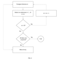
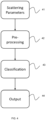
- FIG. 4 is a flowchart illustrating the various processing steps according to an embodiment of the invention.
- the method begins at step 41 where a set of scattering parameters is determined for the body part in a manner as described above with respect to Figure 3 .
- This step will also include using the scattering parameters to generate an output indicative of the internal structure of the body part to identify a region of interest within the body part.
- the method of the invention will proceed to step 42, at which point the set of scattering parameters for the region of interest is processed and analysed pre-classification.
- the processor 4 will process the set of scattering parameters to determine information that is indicative of and/or derived from the change of the scattering parameters over the range of frequency.
- This information is then used at step 43 in order to classify the tissue in the region of interest based on a comparison with a "classifier" that has been trained on data obtained for known tissue types.
- the classification may include identifying the type of tissue in the region of interest (as e.g. skin, muscle, fat, adipose etc.), and/or identifying the tissue as being either malignant or benign.
- the result of the classification may be output to aid diagnosis by a clinician.
- the output may take the form of a tissue identification (e.g. an identification that the tissue is skin, muscle or fat etc.), a binary decision (e.g. malignant/benign), or a likelihood indication (e.g. an indication that the tissue is 90% likely to be benign).
- any suitable and desired pre-classification processing method may be used at step 42 in order to process the set of scattering parameters, and that the specific processing that is performed on the set of scattering parameters will depend on the type of classifier that has been trained and that is to be used at step 43.
- Figure 5 illustrates a data flow diagram illustrating a model-based classification method in accordance with an embodiment of the invention described herein.
- the set of scattering parameters over the range of frequencies is determined for the region of interest at step 51. This corresponds to step 41 illustrated in Figure 4 .
- the set of scattering parameters will accordingly then be subjected to a pre-classification process in order to determine information that is representative of and/or based on the change of scattering parameters over the range of frequencies, as described with respect to step 42 of Figure 4 .
- the pre-classification processing will include two steps, a model fitting step (step 52) and a model parameter determination step (step 53).
- a model is fitted to the scattering parameters over the range of frequencies at step 52.
- the model may be any suitable and desired model that can be fitted to the change of scattering parameters over the range of frequencies or that can be fitted to data that has been derived from the change of scattering parameters over the range of frequencies.
- the model may be a dispersion model or a geometry model, as appropriate.
- Z 1 ( ⁇ ) is the frequency dependent impedance on the incident side of the boundary (e.g. the impedance of the body part in general) and Z 2 ( ⁇ ) is the impedance on the transmitting side of the boundary (i.e. the impedance of the region of interest).
- the impedance is related to permittivity through:
- the frequency dependent permittivity on the transmitting side of the boundary can be calculated from the scattering parameter(s) over the range of frequencies.
- the resulting set of permittivity values over the range of frequencies can then be used to fit a Debye model to the data.
- a single pole Debye model for the low microwave band (0.5-20GHz) can be used to model the calculated frequency dependent permittivity for the region of interest.
- the values of the parameters, ⁇ ⁇ and ⁇ s are derived directly from the Debye model, at step 53.
- the derived values of ⁇ ⁇ and ⁇ s can be used to assess the likelihood that the tissue in the region of interest is cancerous (i.e. to classify the tissue in the region of interest).
- the assessment could take the form of a comparison between the derived values of ⁇ ⁇ and/or ⁇ s and a linear or non-linear classifier trained on known, existing data.
- a "likelihood of cancer" probability value could be provided based on the ⁇ and ⁇ s values.
- a classifier is trained (pre-determined) by performing the above model fitting method on scattering parameter data obtained (using the method of Figure 3 ) from sample lesions with known, histological diagnosis as being malignant (Ca) or benign (Cyst (Cy)).
- the change in the permittivity i.e. the change in ⁇ 2 ( ⁇ ) with frequency may be modelled using a single pole Drude model of permittivity for biological tissues in the low microwave band (0.5-20GHz): where ⁇ ⁇ is the relative permittivity at infinite frequency, ⁇ 0 is the permittivity of free space, ⁇ ⁇ is the polarisation intensity, ⁇ is the angular frequency, ⁇ is the time constant, a is an exponent parameter, which takes a value between 0 and 1, allowing the description of different spectral shapes and ⁇ s is the static conductivity contribution.
- the scattering parameters may be subjected to an earlier processing step in advance of the model fitting.
- the scattering parameters may be subjected to one or more feature reduction processes, as is described below, and the model may accordingly be fitted to such a processed set of scattering parameters.
- the model may be fitted to a subset of frequencies comprising some but not all of the overall range of frequencies.
- the range of frequencies may be divided into a plurality of bands of frequencies and a model may be fitted to the average values of the scattering parameters (or corresponding permittivity values) for respective bands of frequencies, as desired.
- the bands of frequencies used in such an arrangement may be selected based on a principal component analysis of the scattering parameters over the range of frequencies.
- the medical imaging system 2 of the invention will have recorded more data (or rather more complex data) than is required to accurately classify a region of interest.
- the system may derive scattering parameter data for more bands or ranges of frequencies than are actually needed to accurately classify a region of interest.
- the scattering parameter data over the range of frequencies will undergo a process of "feature reduction", which is essentially a method of compressing the features (feature space) of the scattering parameter data to the most informative features for tissue classification.
- the reduced feature scattering parameter data (which has increased separability) for a region of interest can then be analysed to classify the region of interest. Specifically, the reduced feature scattering parameter data over the range of frequencies for a region of interest may be compared to a corresponding classifier derived from scattering parameter data (detected for earlier samples of known tissue types) which has undergone a corresponding process of feature reduction.
- the pre-processing step 42 in Figure 4 will, in embodiments, comprise performing a feature reduction process on the scattering parameters obtained over the range of frequencies for the region of interest.
- Such feature reduction processes may be used in combination with other pre-processing methods, such as the model fitting method described above, or may be used separately in alternative arrangements, depending on the type of classifier to be used in step 43 of Figure 4 to classify the tissue in the region of interest.
- the processor 4 will perform a feature reduction process on the scattering parameters pre-classification by dividing the range of frequencies into a plurality of bands and determine an average magnitude value of the scattering parameters for the region of interest for respective bands of frequency.
- the bands may be selected in any suitable or desired manner.
- the bands may be selected manually.
- the two or more bands are selected by performing a feature selection process, such as a genetic algorithm, to automatically select the most suitable or relevant bands for the classification process.
- the processor 4 classifies the region of interest based on an average magnitude value of the scattering parameters for the region of interest over a first frequency range (a first band) and on an average magnitude value of the scattering parameters for the region of interest over a second frequency range (a second band).
- the present invention may determine a classifier which allows new samples (which have not been subjected to separate analysis) to be classified as, e.g., either malignant or benign, based on the sample's average magnitude response for the different frequency bands.
- the data from a study performed based on 48 patients exhibiting unifocal lesions with a histological diagnosis as being malignant (Ca) or benign (Fibroadenoma (Fa) and Cyst (Cy)) was used to determine a classifier for identifying the type of tissue in the region of interest based on the change of scattering parameters over the range of frequency.
- the evaluated studies comprised 17 cases with malignant diagnosis and 31 cases with benign diagnosis (12 Fa and 19 Cy).
- the radio frequency response was recorded for the region of interest of each patient over the 3 to 8 GHz range.
- the 3 to 8 GHz range was split into three bands: the low frequency band (from 3 to 4.6 GHz), the medium frequency band (from 4.7 to 6.3 GHz) and the high frequency band (from 6.4 to 8.9 GHz), where the three bands used in this example have been selected manually.
- the average magnitude response for each band (labelled as R, G and B for low, medium and high frequencies, respectively) was computed.
- Figures 6 and 7 show examples of such scatter plots. Specifically, Figure 6 shows a plot of R versus B, whereas Figure 7 shows a plot of G versus B.
- Figure 6 shows a plot of R versus B
- Figure 7 shows a plot of G versus B.
- the selection of different combinations of RGB frequency bands corresponds to a manual feature selection, although an automatic feature selection method could have been used.
- the samples may be used to derive a linear classifier 61, 71 which allows new samples (which have not been subjected to separate analysis) to be classified as either malignant or benign based on the sample's average magnitude response for the different frequency bands.
- the linear classifier 61, 71 defines an optimised decision boundary (which in this case corresponds to a straight line) which divides the plot into malignant and benign classes.
- Any known linear discriminant method may be used for deriving a linear classifier 61, 71 based on the data, such as Linear Discriminant Analysis (LDA), logistic regression etc.
- LDA Linear Discriminant Analysis
- the different plots show different degrees of discrimination of malignant from benign cases. Specifically, it has been found that the most accurate classification is provided by the R versus B plot (i.e., High against Low frequency magnitude), which allows to discriminate malignant from benign cases with a positive predicted value (PPV) of 76%, followed by the G vs B plot (i.e., Medium against Low frequency magnitude), with a PPV of 73%.
- the use of the R versus B plot may provide a more accurate classification as the frequency ranges are non-adjacent.
- Figures 6 and 7 have been described with respect to deriving a linear classifier, this is not required. It is possible, for example, for the samples to be used to derive a non-linear classifier which allows new samples (which have not been subjected to separate analysis) to be classified as either malignant or benign based on the sample's average magnitude response for the different frequency bands.
- the non-linear classifier may define a more optimised decision boundary (compared to that of a straight line) which divides the plot into malignant and benign classes. Any known non-linear discriminant method may be used for deriving a non-linear classifier, such as a support vector machine or neural network method, etc.
- multivariant analysis involves projecting scattering parameters to a different coordinate space in which features relating to the change of scattering parameters with frequency have greater separability (e.g. compared to their separability in the original space within which the scattering parameters are defined). These features can then be compared against a classifier (defined for that coordinate space) to classify or identify a tissue in a region of interest.
- a classifier defined for that coordinate space
- ICA independent component analysis
- multivariant analysis comprises performing a principle component analysis (PCA) to transform the scattering data to a new set of axes.
- PCA principle component analysis
- principal component analysis will include performing an orthogonal transformation on the set of scattering parameters derived for the region of interest over the range of frequencies to convert the set of scattering parameters into a set of values representing variables called principal components.
- the number of distinct principal components is equal to the number of original features, i.e. the number of frequency points over the range of frequencies.
- a classifier is trained by performing PCA on the scattering parameters obtained (using the method of Figure 3 ) from a study of a number, m, of lesion samples with a known, histological diagnosis as being malignant (Ca) or benign (Cyst (Cy)).
- m a number of lesion samples with a known, histological diagnosis as being malignant (Ca) or benign (Cyst (Cy)).
- the scattering parameters for this study were obtained by stepping the frequency over 101 discrete frequency pulses over the frequency range 3-8 GHz.
- the scattering parameters from all 37 lesion samples may be put together into a single matrix, A, where each row in the matrix corresponds to the scattering parameters for a given lesion sample.
- the principal components are then determined from the scattering parameter matrix A by first calculating the covariance matrix, C, which is indicative of the extent to which the frequencies correlate to each other.
- Finding the eigenvectors V and eigenvalues D of the covariance matrix C can be thought of as fitting an n -dimensional ellipsoid (where n corresponds to the number of original features) to the variance of the data, where each axis of the ellipsoid represents a principal component.
- Each eigenvector (which is mutually orthogonal to the other eigenvectors) can then be used as an axis of the coordinate space to which the scattering parameters are projected.
- an eigenvector, v i in V can be seen as an axis of a coordinate system that the scattering parameter data, S, can be projected onto, where the value, S' i , is a scattering parameter projected (i.e. linearly transformed) onto the given eigenvector v i axis:
- S' i corresponds to the distance from the origin of the coordinate system along the direction of the i th principal component.
- the value of this distance therefore relates to the correlation of the variance described by its associated principal component.
- the appropriately transformed/projected scattering parameters over the range of frequencies can then be subjected to a discriminant analysis method to determine a classifier.
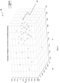
- Figure 8 demonstrates the results of performing PCA on the scattering parameters obtained for the 37 lesion samples mentioned above by stepping the frequency over 101 discrete frequency pulses over the frequency range 3-8 GHz.
- Figure 8 shows a co-ordinate system 80 having only three-dimensions having axes corresponding to the first, second and third principal components (i.e. the three most significant principal components having the largest variance).
- any number of dimensions (or principal components) can be used in the classification process.
- the maximum number of principle components is limited to a value equal to the number of dimensions in the original scattering parameter data.
- a Linear Discriminant Analysis (LDA) method was adopted to find a hyper plane 81 that best separates the malignant and benign tissue types based on the samples' position within the projected space.
- Any known linear discriminant method may be used for deriving a linear classifier based on the data, such as Linear Discriminant Analysis (LDA), logistic regression etc.
- a non-linear classifier may be used to define a more optimised decision boundary (compared to that of a plane).
- Any suitable non-linear discriminant method may be used to determine a non-linear classifier, such as a support vector machine method or a neural network method, etc.
- a positive predicted value (PPV) of 68% is achieved. It was also found that by increasing the number of principal axes (and thus the dimensions of the coordinate space to which the scattering parameters are projected) to 10, a PPV of 81% is achieved.
- the classifier may be trained based on scattering parameters projected to a coordinate space having any number of principal components.
- new samples (which have not been subjected to separate analysis) can be compared to the determined hyperplane 81 to be classified as either malignant or benign.
- the scattering parameters for the region of interest may be projected to the coordinate space (a reference coordinate space) that has been derived based on a principal component analysis of scattering parameters determined for the 37 lesion samples mentioned above, and the region of interest may be classified based on the position of the projected scattering parameters within the coordinate space.
- the scattering parameters may undergo a pre-classification process of feature reduction and/or selection, e.g. as described above, and the processed set of scattering parameters may be used as the inputs to the PCA process (i.e. may be projected to the reference coordinate space).
- the scattering parameters over a subset of frequencies may be used in the PCA (to project the scattering parameters for the subset of frequencies to the predefined reference coordinate space).
- the range of frequencies may be divided into a plurality of bands of frequencies and the average scattering parameters for respective bands of frequencies may be used as the inputs to the PCA process (i.e. may be projected to the predefined reference coordinate space), as desired.
- the classification of the region of interest can be made based on the scattering parameters from which the region of interest is first identified. That is, the scattering parameters derived for generating an image can be used not only to identify a region of interest, but also to identify the type of tissue in the region. Consequently, it is not necessary to obtain any additional data after determining a region of interest in order to make this classification which can be derived automatically.
- tissue as either malignant or benign
- present invention may be extended to encompass classification between other types of tissue, such as to classify/identify different types of tissue (e.g. skin, muscle, fat, adipose etc.) and/or lesions (e.g. carcinoma, cysts, fibroadenoma, Lipoma).
- tissue e.g. skin, muscle, fat, adipose etc.
- lesions e.g. carcinoma, cysts, fibroadenoma, Lipoma.
- This may be done by determining ("training") a classifier using the methods described above, based on scattering parameters obtained for known tissue samples corresponding to the tissue types to be classified in subsequent samples.
Landscapes
- Health & Medical Sciences (AREA)
- Life Sciences & Earth Sciences (AREA)
- Engineering & Computer Science (AREA)
- Physics & Mathematics (AREA)
- Public Health (AREA)
- Medical Informatics (AREA)
- Veterinary Medicine (AREA)
- General Health & Medical Sciences (AREA)
- Animal Behavior & Ethology (AREA)
- Surgery (AREA)
- Molecular Biology (AREA)
- Biophysics (AREA)
- Pathology (AREA)
- Biomedical Technology (AREA)
- Heart & Thoracic Surgery (AREA)
- Artificial Intelligence (AREA)
- Evolutionary Computation (AREA)
- Radiology & Medical Imaging (AREA)
- Signal Processing (AREA)
- Psychiatry (AREA)
- Physiology (AREA)
- Computer Vision & Pattern Recognition (AREA)
- Fuzzy Systems (AREA)
- Mathematical Physics (AREA)
- Nuclear Medicine, Radiotherapy & Molecular Imaging (AREA)
- Reproductive Health (AREA)
- Gynecology & Obstetrics (AREA)
- Ultra Sonic Daignosis Equipment (AREA)
- Measuring And Recording Apparatus For Diagnosis (AREA)
- Apparatus For Radiation Diagnosis (AREA)
Claims (13)
- Mikrowellenbildgebungssystem (2), umfassend:ein Mikrowellenantennenarray (6), umfassend eine Sendeantenne und eine Vielzahl von Empfangsantennen, wobei die Sendeantenne dafür ausgelegt ist, Mikrowellensignale über einen Frequenzbereich zu senden, zu dem Zweck, einen Körperteil (36) eines Patienten zu beleuchten, und die Empfangsantennen dafür ausgelegt sind, die Mikrowellensignale nach Streuung innerhalb des Körperteils (36) zu empfangen und Daten zu erfassen, die die empfangenen Mikrowellensignale repräsentieren, die durch Streuung aufgrund von Objekten innerhalb des Körperteils (36) beeinflusst werden; undeinen Prozessor (4);dadurch gekennzeichnet, dass der Prozessor (4) für folgende Vorgänge ausgelegt ist:Verarbeiten der erfassten Daten zum Bestimmen einer Vielzahl von Sätzen von Streuparametern für eine Vielzahl von Punkten innerhalb des Körperteils (36), wobei jeder Satz von Streuparametern das an einem entsprechenden Punkt innerhalb des Körperteils gestreute Feld bei jeweiligen Frequenzen über den Frequenzbereich (36) repräsentiert;Erzeugen einer Ausgabe, die die innere Struktur des Körperteils (36) angibt, unter Verwendung der Vielzahl von Sätzen von Streuparametern zum Identifizieren eines Bereichs von Interesse innerhalb des Körperteils (36); undKlassifizieren des Bereichs von Interesse auf der Grundlage einer darin befindlichen Art von Gewebe, indem die Änderung der Streuparameter in einem Satz von Streuparametern, der dem Bereich von Interesse entspricht, über den Frequenzbereich analysiert wird.
- Mikrowellenbildgebungssystem (2) nach Anspruch 1, wobei der Prozessor (4) den Bereich von Interesse auf der Grundlage eines Durchschnittswertes der Streuparameter in dem Satz von Streuparametern, der dem Bereich von Interesse entspricht, über einen ersten Frequenzbereich und auf der Grundlage eines Durchschnittswertes der Streuparameter in dem Satz von Streuparametern, der dem Bereich von Interesse entspricht, über einen zweiten Frequenzbereich klassifiziert.
- Mikrowellenbildgebungssystem (2) nach Anspruch 2, wobei der Prozessor (4) den Bereich von Interesse auf der Grundlage einer Entscheidungsgrenze klassifiziert, die Werte für den ersten und den zweiten Frequenzbereich in mindestens zwei Klassen unterteilt.
- Mikrowellenbildgebungssystem (2) nach Anspruch 2 oder 3, wobei der erste und der zweite Frequenzbereich nicht benachbart sind.
- Mikrowellenbildgebungssystem (2) nach einem der vorhergehenden Ansprüche, wobei:das Analysieren der Änderung der Streuparameter in dem Satz von Streuparametern, der dem Bereich von Interesse über den Frequenzbereich entspricht, das Bestimmen einer Änderung der Permittivität mit der Frequenz auf der Grundlage der Änderung der Streuparameter im Satz von Streuparametern über den Frequenzbereich umfasst; undder Prozessor (4) dafür ausgelegt ist, den Bereich von Interesse auf der Grundlage der bestimmten Änderung der Permittivität mit der Frequenz zu klassifizieren.
- Mikrowellenbildgebungssystem (2) nach einem der vorhergehenden Ansprüche, wobei:das Analysieren der Änderung der Streuparameter in dem Satz von Streuparametern, die dem Bereich von Interesse über den Frequenzbereich entsprechen, das Bestimmen eines Wertes der statischen Leitfähigkeit und/oder eines Polarisationsintensitätswertes für den Bereich von Interesse auf der Grundlage der Änderung der Streuparameter im Satz von Streuparametern über den Frequenzbereich umfasst; undder Prozessor (4) dafür ausgelegt ist, den Bereich von Interesse auf der Grundlage einer vorbestimmten Korrelation zwischen Gewebeart und dem Wert der statischen Leitfähigkeit und/oder dem Polarisationsintensitätswert zu klassifizieren.
- Mikrowellenbildgebungssystem (2) nach einem der vorhergehenden Ansprüche, wobei:der Prozessor (4) dafür ausgelegt ist, die Streuparameter in dem Satz von Streuparametern, die dem Bereich von Interesse entsprechen, auf einen vordefinierten Referenzkoordinatenraum zu projizieren; undder Prozessor (4) dafür ausgelegt ist, den Bereich von Interesse auf der Grundlage der Position der projizierten Streuparameter innerhalb des vordefinierten Referenzkoordinatenraums zu klassifizieren.
- Mikrowellenbildgebungssystem (2) nach Anspruch 7, wobei der vordefinierte Referenzkoordinatenraum eine Vielzahl von Achsen umfasst, wobei jede Achse einer Hauptkomponente eines Satzes von Referenzdaten entspricht.
- Mikrowellenbildgebungssystem (2) nach Anspruch 8, wobei der Satz von Referenzdaten eine Vielzahl von Sätzen von Streuparametern umfasst, die für jeweilige Sätze von Probengeweben bekannter Gewebearten erhalten wurden.
- Mikrowellenbildgebungssystem (2) nach einem der vorhergehenden Ansprüche, wobei der Prozessor (4) den Bereich von Interesse als bösartig oder gutartig klassifiziert.
- Mikrowellenbildgebungssystem (2) nach einem der vorhergehenden Ansprüche, wobei das Mikrowellenantennenarray auf einem Substrat ausgebildet ist, wobei das Substrat zur Anpassung an den Körperteil (36) konturiert oder konturierbar ist.
- Mikrowellenbildgebungssystem (2) nach Anspruch 11, wobei das Substrat halbkugelförmig ist.
- Mikrowellenbildgebungssystem (2) nach einem der vorhergehenden Ansprüche, wobei der Prozessor ferner dafür ausgelegt ist, ein Bild der inneren Struktur der Brust auf der Grundlage der Vielzahl von Sätzen von Streuparametern zu erzeugen.
Applications Claiming Priority (2)
| Application Number | Priority Date | Filing Date | Title |
|---|---|---|---|
| GBGB1621659.0A GB201621659D0 (en) | 2016-12-19 | 2016-12-19 | A medical imaging system and method |
| PCT/GB2017/053825 WO2018115858A1 (en) | 2016-12-19 | 2017-12-19 | A medical imaging system and method |
Publications (2)
| Publication Number | Publication Date |
|---|---|
| EP3554339A1 EP3554339A1 (de) | 2019-10-23 |
| EP3554339B1 true EP3554339B1 (de) | 2024-04-10 |
Family
ID=58284554
Family Applications (1)
| Application Number | Title | Priority Date | Filing Date |
|---|---|---|---|
| EP17818612.8A Active EP3554339B1 (de) | 2016-12-19 | 2017-12-19 | System zur medizinischen bildgebung |
Country Status (5)
| Country | Link |
|---|---|
| US (1) | US20190336034A1 (de) |
| EP (1) | EP3554339B1 (de) |
| JP (1) | JP7090086B2 (de) |
| GB (1) | GB201621659D0 (de) |
| WO (1) | WO2018115858A1 (de) |
Families Citing this family (4)
| Publication number | Priority date | Publication date | Assignee | Title |
|---|---|---|---|---|
| CN121390150A (zh) * | 2018-11-14 | 2026-01-23 | 直观外科手术操作公司 | 用于有效的组织分割的卷积神经网络 |
| WO2021026592A1 (en) * | 2019-08-09 | 2021-02-18 | EMvision Medical Devices Ltd | Apparatus and process for electromagnetic imaging |
| SE2050674A1 (en) * | 2020-06-09 | 2021-12-10 | Medfield Diagnostics Ab | Classification of radio frequency scattering data |
| US20260102073A1 (en) * | 2022-12-20 | 2026-04-16 | Wave View Imaging Inc. | Method and system for microwave scanning of biological tissue |
Family Cites Families (6)
| Publication number | Priority date | Publication date | Assignee | Title |
|---|---|---|---|---|
| US7809427B2 (en) * | 2005-02-11 | 2010-10-05 | Wisconsin Alumni Research Foundation | Time domain inverse scattering techniques for use in microwave imaging |
| GB0721693D0 (en) | 2007-11-05 | 2007-12-12 | Univ Bristol | Antenna for investigating structure of human or animal |
| WO2010143691A1 (ja) | 2009-06-10 | 2010-12-16 | 国立大学法人静岡大学 | 診断装置 |
| PL2457195T3 (pl) * | 2009-07-23 | 2018-03-30 | Medfield Diagnostics Ab | Klasyfikacja danych dotyczących rozpraszania mikrofalowego |
| JP2013113603A (ja) | 2011-11-25 | 2013-06-10 | Kyushu Univ | マイクロ波イメージングシステム及びイメージング処理方法 |
| US10258251B2 (en) * | 2013-02-15 | 2019-04-16 | Mitos Medikal Teknolojiler Sanayi Ve Ticaret Anonim Sirketi | Breast cancer imaging device through microwave surface impedance |
-
2016
- 2016-12-19 GB GBGB1621659.0A patent/GB201621659D0/en not_active Ceased
-
2017
- 2017-12-19 JP JP2019533013A patent/JP7090086B2/ja active Active
- 2017-12-19 US US16/470,910 patent/US20190336034A1/en not_active Abandoned
- 2017-12-19 EP EP17818612.8A patent/EP3554339B1/de active Active
- 2017-12-19 WO PCT/GB2017/053825 patent/WO2018115858A1/en not_active Ceased
Also Published As
| Publication number | Publication date |
|---|---|
| WO2018115858A1 (en) | 2018-06-28 |
| US20190336034A1 (en) | 2019-11-07 |
| EP3554339A1 (de) | 2019-10-23 |
| JP7090086B2 (ja) | 2022-06-23 |
| GB201621659D0 (en) | 2017-02-01 |
| JP2020513886A (ja) | 2020-05-21 |
Similar Documents
| Publication | Publication Date | Title |
|---|---|---|
| O'Halloran et al. | Quasi-multistatic MIST beamforming for the early detection of breast cancer | |
| EP2967477B1 (de) | Gegenüber hintergrund und hautstörungen robuste mikrowellenbildgebung | |
| US7809427B2 (en) | Time domain inverse scattering techniques for use in microwave imaging | |
| Santorelli et al. | Investigation of classifiers for tumor detection with an experimental time-domain breast screening system | |
| Godinho et al. | Experimental evaluation of an axillary microwave imaging system to aid breast cancer staging | |
| Santorelli et al. | Image classification for a time-domain microwave radar system: Experiments with stable modular breast phantoms | |
| US20190336034A1 (en) | Medical Imaging System and Method | |
| Fasoula et al. | Super-resolution radar imaging for breast cancer detection with microwaves: The integrated information selection criteria | |
| Conceicao et al. | Investigation of classifiers for early-stage breast cancer based on radar target signatures | |
| Mohareri et al. | Multi-parametric 3D quantitative ultrasound vibro-elastography imaging for detecting palpable prostate tumors | |
| Maklad et al. | Neighborhood-based algorithm to facilitate the reduction of skin reflections in radar-based microwave imaging | |
| Ojaroudi et al. | A novel machine learning approach of hemorrhage stroke detection in differential microwave head imaging system | |
| Guo et al. | Clutter Removal in the Latent Space Using Data-Driven Method for Clinical Microwave Head Imaging | |
| WO2018083492A1 (en) | A breast density meter and method | |
| Kandasamy et al. | Deep learning algorithm for automatic breast tumour detection and classification from electromagnetic scattering data | |
| Ueda et al. | Clinical Validations on Effective Skin Clutter Rejection for Microwave Breast Cancer Diagnosis | |
| Anwar et al. | Wearable RF sensing and imaging system for non-invasive vascular dementia detection | |
| Siebers et al. | Computer aided diagnosis of parotid gland lesions using ultrasonic multi-feature tissue characterization | |
| Chen et al. | Effect of lesion morphology on microwave signature in ultra-wideband breast imaging: A preliminary two-dimensional investigation | |
| Aldhaeebi et al. | Breast tumor diagnosis using machine learning with microwave probes | |
| TR2021012195A2 (tr) | Mi̇krodalga meme kanseri̇ tarama si̇stemi̇ | |
| Hilger et al. | Could we use UWB sensing for breast cancer detection? | |
| EP3466321A1 (de) | Brustdichtemessgerät und -verfahren | |
| DasGupta | Artifact Reduction Strategy for Radar-based Microwave Imaging Designed for Medical Applications | |
| Conceicao | The development of ultra wideband scanning techniques for detection and classification of breast cancer |
Legal Events
| Date | Code | Title | Description |
|---|---|---|---|
| STAA | Information on the status of an ep patent application or granted ep patent |
Free format text: STATUS: UNKNOWN |
|
| STAA | Information on the status of an ep patent application or granted ep patent |
Free format text: STATUS: THE INTERNATIONAL PUBLICATION HAS BEEN MADE |
|
| PUAI | Public reference made under article 153(3) epc to a published international application that has entered the european phase |
Free format text: ORIGINAL CODE: 0009012 |
|
| STAA | Information on the status of an ep patent application or granted ep patent |
Free format text: STATUS: REQUEST FOR EXAMINATION WAS MADE |
|
| 17P | Request for examination filed |
Effective date: 20190620 |
|
| AK | Designated contracting states |
Kind code of ref document: A1 Designated state(s): AL AT BE BG CH CY CZ DE DK EE ES FI FR GB GR HR HU IE IS IT LI LT LU LV MC MK MT NL NO PL PT RO RS SE SI SK SM TR |
|
| AX | Request for extension of the european patent |
Extension state: BA ME |
|
| DAV | Request for validation of the european patent (deleted) | ||
| DAX | Request for extension of the european patent (deleted) | ||
| GRAP | Despatch of communication of intention to grant a patent |
Free format text: ORIGINAL CODE: EPIDOSNIGR1 |
|
| STAA | Information on the status of an ep patent application or granted ep patent |
Free format text: STATUS: GRANT OF PATENT IS INTENDED |
|
| INTG | Intention to grant announced |
Effective date: 20231027 |
|
| GRAS | Grant fee paid |
Free format text: ORIGINAL CODE: EPIDOSNIGR3 |
|
| GRAA | (expected) grant |
Free format text: ORIGINAL CODE: 0009210 |
|
| STAA | Information on the status of an ep patent application or granted ep patent |
Free format text: STATUS: THE PATENT HAS BEEN GRANTED |
|
| AK | Designated contracting states |
Kind code of ref document: B1 Designated state(s): AL AT BE BG CH CY CZ DE DK EE ES FI FR GB GR HR HU IE IS IT LI LT LU LV MC MK MT NL NO PL PT RO RS SE SI SK SM TR |
|
| REG | Reference to a national code |
Ref country code: GB Ref legal event code: FG4D |
|
| REG | Reference to a national code |
Ref country code: CH Ref legal event code: EP |
|
| REG | Reference to a national code |
Ref country code: DE Ref legal event code: R096 Ref document number: 602017080910 Country of ref document: DE |
|
| REG | Reference to a national code |
Ref country code: IE Ref legal event code: FG4D |
|
| REG | Reference to a national code |
Ref country code: LT Ref legal event code: MG9D |
|
| REG | Reference to a national code |
Ref country code: NL Ref legal event code: MP Effective date: 20240410 |
|
| REG | Reference to a national code |
Ref country code: AT Ref legal event code: MK05 Ref document number: 1674011 Country of ref document: AT Kind code of ref document: T Effective date: 20240410 |
|
| PG25 | Lapsed in a contracting state [announced via postgrant information from national office to epo] |
Ref country code: NL Free format text: LAPSE BECAUSE OF FAILURE TO SUBMIT A TRANSLATION OF THE DESCRIPTION OR TO PAY THE FEE WITHIN THE PRESCRIBED TIME-LIMIT Effective date: 20240410 |
|
| PG25 | Lapsed in a contracting state [announced via postgrant information from national office to epo] |
Ref country code: NL Free format text: LAPSE BECAUSE OF FAILURE TO SUBMIT A TRANSLATION OF THE DESCRIPTION OR TO PAY THE FEE WITHIN THE PRESCRIBED TIME-LIMIT Effective date: 20240410 |
|
| PG25 | Lapsed in a contracting state [announced via postgrant information from national office to epo] |
Ref country code: IS Free format text: LAPSE BECAUSE OF FAILURE TO SUBMIT A TRANSLATION OF THE DESCRIPTION OR TO PAY THE FEE WITHIN THE PRESCRIBED TIME-LIMIT Effective date: 20240810 |
|
| PG25 | Lapsed in a contracting state [announced via postgrant information from national office to epo] |
Ref country code: BG Free format text: LAPSE BECAUSE OF FAILURE TO SUBMIT A TRANSLATION OF THE DESCRIPTION OR TO PAY THE FEE WITHIN THE PRESCRIBED TIME-LIMIT Effective date: 20240410 |
|
| PG25 | Lapsed in a contracting state [announced via postgrant information from national office to epo] |
Ref country code: FI Free format text: LAPSE BECAUSE OF FAILURE TO SUBMIT A TRANSLATION OF THE DESCRIPTION OR TO PAY THE FEE WITHIN THE PRESCRIBED TIME-LIMIT Effective date: 20240410 Ref country code: HR Free format text: LAPSE BECAUSE OF FAILURE TO SUBMIT A TRANSLATION OF THE DESCRIPTION OR TO PAY THE FEE WITHIN THE PRESCRIBED TIME-LIMIT Effective date: 20240410 |
|
| PG25 | Lapsed in a contracting state [announced via postgrant information from national office to epo] |
Ref country code: GR Free format text: LAPSE BECAUSE OF FAILURE TO SUBMIT A TRANSLATION OF THE DESCRIPTION OR TO PAY THE FEE WITHIN THE PRESCRIBED TIME-LIMIT Effective date: 20240711 |
|
| PG25 | Lapsed in a contracting state [announced via postgrant information from national office to epo] |
Ref country code: PT Free format text: LAPSE BECAUSE OF FAILURE TO SUBMIT A TRANSLATION OF THE DESCRIPTION OR TO PAY THE FEE WITHIN THE PRESCRIBED TIME-LIMIT Effective date: 20240812 |
|
| PG25 | Lapsed in a contracting state [announced via postgrant information from national office to epo] |
Ref country code: ES Free format text: LAPSE BECAUSE OF FAILURE TO SUBMIT A TRANSLATION OF THE DESCRIPTION OR TO PAY THE FEE WITHIN THE PRESCRIBED TIME-LIMIT Effective date: 20240410 |
|
| PG25 | Lapsed in a contracting state [announced via postgrant information from national office to epo] |
Ref country code: AT Free format text: LAPSE BECAUSE OF FAILURE TO SUBMIT A TRANSLATION OF THE DESCRIPTION OR TO PAY THE FEE WITHIN THE PRESCRIBED TIME-LIMIT Effective date: 20240410 |
|
| PG25 | Lapsed in a contracting state [announced via postgrant information from national office to epo] |
Ref country code: PL Free format text: LAPSE BECAUSE OF FAILURE TO SUBMIT A TRANSLATION OF THE DESCRIPTION OR TO PAY THE FEE WITHIN THE PRESCRIBED TIME-LIMIT Effective date: 20240410 |
|
| PG25 | Lapsed in a contracting state [announced via postgrant information from national office to epo] |
Ref country code: LV Free format text: LAPSE BECAUSE OF FAILURE TO SUBMIT A TRANSLATION OF THE DESCRIPTION OR TO PAY THE FEE WITHIN THE PRESCRIBED TIME-LIMIT Effective date: 20240410 |
|
| PG25 | Lapsed in a contracting state [announced via postgrant information from national office to epo] |
Ref country code: PT Free format text: LAPSE BECAUSE OF FAILURE TO SUBMIT A TRANSLATION OF THE DESCRIPTION OR TO PAY THE FEE WITHIN THE PRESCRIBED TIME-LIMIT Effective date: 20240812 Ref country code: PL Free format text: LAPSE BECAUSE OF FAILURE TO SUBMIT A TRANSLATION OF THE DESCRIPTION OR TO PAY THE FEE WITHIN THE PRESCRIBED TIME-LIMIT Effective date: 20240410 Ref country code: NO Free format text: LAPSE BECAUSE OF FAILURE TO SUBMIT A TRANSLATION OF THE DESCRIPTION OR TO PAY THE FEE WITHIN THE PRESCRIBED TIME-LIMIT Effective date: 20240710 Ref country code: LV Free format text: LAPSE BECAUSE OF FAILURE TO SUBMIT A TRANSLATION OF THE DESCRIPTION OR TO PAY THE FEE WITHIN THE PRESCRIBED TIME-LIMIT Effective date: 20240410 Ref country code: IS Free format text: LAPSE BECAUSE OF FAILURE TO SUBMIT A TRANSLATION OF THE DESCRIPTION OR TO PAY THE FEE WITHIN THE PRESCRIBED TIME-LIMIT Effective date: 20240810 Ref country code: HR Free format text: LAPSE BECAUSE OF FAILURE TO SUBMIT A TRANSLATION OF THE DESCRIPTION OR TO PAY THE FEE WITHIN THE PRESCRIBED TIME-LIMIT Effective date: 20240410 Ref country code: GR Free format text: LAPSE BECAUSE OF FAILURE TO SUBMIT A TRANSLATION OF THE DESCRIPTION OR TO PAY THE FEE WITHIN THE PRESCRIBED TIME-LIMIT Effective date: 20240711 Ref country code: FI Free format text: LAPSE BECAUSE OF FAILURE TO SUBMIT A TRANSLATION OF THE DESCRIPTION OR TO PAY THE FEE WITHIN THE PRESCRIBED TIME-LIMIT Effective date: 20240410 Ref country code: ES Free format text: LAPSE BECAUSE OF FAILURE TO SUBMIT A TRANSLATION OF THE DESCRIPTION OR TO PAY THE FEE WITHIN THE PRESCRIBED TIME-LIMIT Effective date: 20240410 Ref country code: BG Free format text: LAPSE BECAUSE OF FAILURE TO SUBMIT A TRANSLATION OF THE DESCRIPTION OR TO PAY THE FEE WITHIN THE PRESCRIBED TIME-LIMIT Effective date: 20240410 Ref country code: AT Free format text: LAPSE BECAUSE OF FAILURE TO SUBMIT A TRANSLATION OF THE DESCRIPTION OR TO PAY THE FEE WITHIN THE PRESCRIBED TIME-LIMIT Effective date: 20240410 Ref country code: RS Free format text: LAPSE BECAUSE OF FAILURE TO SUBMIT A TRANSLATION OF THE DESCRIPTION OR TO PAY THE FEE WITHIN THE PRESCRIBED TIME-LIMIT Effective date: 20240710 |
|
| REG | Reference to a national code |
Ref country code: DE Ref legal event code: R097 Ref document number: 602017080910 Country of ref document: DE |
|
| PG25 | Lapsed in a contracting state [announced via postgrant information from national office to epo] |
Ref country code: DK Free format text: LAPSE BECAUSE OF FAILURE TO SUBMIT A TRANSLATION OF THE DESCRIPTION OR TO PAY THE FEE WITHIN THE PRESCRIBED TIME-LIMIT Effective date: 20240410 |
|
| PG25 | Lapsed in a contracting state [announced via postgrant information from national office to epo] |
Ref country code: EE Free format text: LAPSE BECAUSE OF FAILURE TO SUBMIT A TRANSLATION OF THE DESCRIPTION OR TO PAY THE FEE WITHIN THE PRESCRIBED TIME-LIMIT Effective date: 20240410 |
|
| PG25 | Lapsed in a contracting state [announced via postgrant information from national office to epo] |
Ref country code: CZ Free format text: LAPSE BECAUSE OF FAILURE TO SUBMIT A TRANSLATION OF THE DESCRIPTION OR TO PAY THE FEE WITHIN THE PRESCRIBED TIME-LIMIT Effective date: 20240410 |
|
| PG25 | Lapsed in a contracting state [announced via postgrant information from national office to epo] |
Ref country code: RO Free format text: LAPSE BECAUSE OF FAILURE TO SUBMIT A TRANSLATION OF THE DESCRIPTION OR TO PAY THE FEE WITHIN THE PRESCRIBED TIME-LIMIT Effective date: 20240410 Ref country code: SK Free format text: LAPSE BECAUSE OF FAILURE TO SUBMIT A TRANSLATION OF THE DESCRIPTION OR TO PAY THE FEE WITHIN THE PRESCRIBED TIME-LIMIT Effective date: 20240410 |
|
| PG25 | Lapsed in a contracting state [announced via postgrant information from national office to epo] |
Ref country code: SM Free format text: LAPSE BECAUSE OF FAILURE TO SUBMIT A TRANSLATION OF THE DESCRIPTION OR TO PAY THE FEE WITHIN THE PRESCRIBED TIME-LIMIT Effective date: 20240410 |
|
| PG25 | Lapsed in a contracting state [announced via postgrant information from national office to epo] |
Ref country code: SM Free format text: LAPSE BECAUSE OF FAILURE TO SUBMIT A TRANSLATION OF THE DESCRIPTION OR TO PAY THE FEE WITHIN THE PRESCRIBED TIME-LIMIT Effective date: 20240410 Ref country code: SK Free format text: LAPSE BECAUSE OF FAILURE TO SUBMIT A TRANSLATION OF THE DESCRIPTION OR TO PAY THE FEE WITHIN THE PRESCRIBED TIME-LIMIT Effective date: 20240410 Ref country code: RO Free format text: LAPSE BECAUSE OF FAILURE TO SUBMIT A TRANSLATION OF THE DESCRIPTION OR TO PAY THE FEE WITHIN THE PRESCRIBED TIME-LIMIT Effective date: 20240410 Ref country code: EE Free format text: LAPSE BECAUSE OF FAILURE TO SUBMIT A TRANSLATION OF THE DESCRIPTION OR TO PAY THE FEE WITHIN THE PRESCRIBED TIME-LIMIT Effective date: 20240410 Ref country code: DK Free format text: LAPSE BECAUSE OF FAILURE TO SUBMIT A TRANSLATION OF THE DESCRIPTION OR TO PAY THE FEE WITHIN THE PRESCRIBED TIME-LIMIT Effective date: 20240410 Ref country code: CZ Free format text: LAPSE BECAUSE OF FAILURE TO SUBMIT A TRANSLATION OF THE DESCRIPTION OR TO PAY THE FEE WITHIN THE PRESCRIBED TIME-LIMIT Effective date: 20240410 |
|
| PG25 | Lapsed in a contracting state [announced via postgrant information from national office to epo] |
Ref country code: IT Free format text: LAPSE BECAUSE OF FAILURE TO SUBMIT A TRANSLATION OF THE DESCRIPTION OR TO PAY THE FEE WITHIN THE PRESCRIBED TIME-LIMIT Effective date: 20240410 |
|
| PLBE | No opposition filed within time limit |
Free format text: ORIGINAL CODE: 0009261 |
|
| STAA | Information on the status of an ep patent application or granted ep patent |
Free format text: STATUS: NO OPPOSITION FILED WITHIN TIME LIMIT |
|
| 26N | No opposition filed |
Effective date: 20250113 |
|
| PG25 | Lapsed in a contracting state [announced via postgrant information from national office to epo] |
Ref country code: SI Free format text: LAPSE BECAUSE OF FAILURE TO SUBMIT A TRANSLATION OF THE DESCRIPTION OR TO PAY THE FEE WITHIN THE PRESCRIBED TIME-LIMIT Effective date: 20240410 |
|
| PG25 | Lapsed in a contracting state [announced via postgrant information from national office to epo] |
Ref country code: MC Free format text: LAPSE BECAUSE OF FAILURE TO SUBMIT A TRANSLATION OF THE DESCRIPTION OR TO PAY THE FEE WITHIN THE PRESCRIBED TIME-LIMIT Effective date: 20240410 |
|
| REG | Reference to a national code |
Ref country code: CH Ref legal event code: PL |
|
| PG25 | Lapsed in a contracting state [announced via postgrant information from national office to epo] |
Ref country code: LU Free format text: LAPSE BECAUSE OF NON-PAYMENT OF DUE FEES Effective date: 20241219 |
|
| PG25 | Lapsed in a contracting state [announced via postgrant information from national office to epo] |
Ref country code: SE Free format text: LAPSE BECAUSE OF FAILURE TO SUBMIT A TRANSLATION OF THE DESCRIPTION OR TO PAY THE FEE WITHIN THE PRESCRIBED TIME-LIMIT Effective date: 20240410 |
|
| REG | Reference to a national code |
Ref country code: BE Ref legal event code: MM Effective date: 20241231 |
|
| PG25 | Lapsed in a contracting state [announced via postgrant information from national office to epo] |
Ref country code: BE Free format text: LAPSE BECAUSE OF NON-PAYMENT OF DUE FEES Effective date: 20241231 |
|
| PG25 | Lapsed in a contracting state [announced via postgrant information from national office to epo] |
Ref country code: FR Free format text: LAPSE BECAUSE OF NON-PAYMENT OF DUE FEES Effective date: 20241231 |
|
| PG25 | Lapsed in a contracting state [announced via postgrant information from national office to epo] |
Ref country code: CH Free format text: LAPSE BECAUSE OF NON-PAYMENT OF DUE FEES Effective date: 20241231 |
|
| PG25 | Lapsed in a contracting state [announced via postgrant information from national office to epo] |
Ref country code: IE Free format text: LAPSE BECAUSE OF NON-PAYMENT OF DUE FEES Effective date: 20241219 |
|
| PGFP | Annual fee paid to national office [announced via postgrant information from national office to epo] |
Ref country code: DE Payment date: 20251215 Year of fee payment: 9 |
|
| PGFP | Annual fee paid to national office [announced via postgrant information from national office to epo] |
Ref country code: GB Payment date: 20251216 Year of fee payment: 9 |