EP3466321A1 - Brustdichtemessgerät und -verfahren - Google Patents
Brustdichtemessgerät und -verfahren Download PDFInfo
- Publication number
- EP3466321A1 EP3466321A1 EP17195569.3A EP17195569A EP3466321A1 EP 3466321 A1 EP3466321 A1 EP 3466321A1 EP 17195569 A EP17195569 A EP 17195569A EP 3466321 A1 EP3466321 A1 EP 3466321A1
- Authority
- EP
- European Patent Office
- Prior art keywords
- data
- breast
- intensity
- density
- parameter value
- Prior art date
- Legal status (The legal status is an assumption and is not a legal conclusion. Google has not performed a legal analysis and makes no representation as to the accuracy of the status listed.)
- Withdrawn
Links
- 210000000481 breast Anatomy 0.000 title claims abstract description 71
- 238000000034 method Methods 0.000 title claims description 29
- 206010028980 Neoplasm Diseases 0.000 claims abstract description 13
- 201000011510 cancer Diseases 0.000 claims abstract description 11
- 210000001519 tissue Anatomy 0.000 description 11
- 239000012530 fluid Substances 0.000 description 6
- 239000011159 matrix material Substances 0.000 description 6
- 230000008878 coupling Effects 0.000 description 5
- 238000010168 coupling process Methods 0.000 description 5
- 238000005859 coupling reaction Methods 0.000 description 5
- 238000002059 diagnostic imaging Methods 0.000 description 5
- 206010006187 Breast cancer Diseases 0.000 description 4
- 208000026310 Breast neoplasm Diseases 0.000 description 4
- 210000002808 connective tissue Anatomy 0.000 description 4
- 238000003384 imaging method Methods 0.000 description 4
- 210000000577 adipose tissue Anatomy 0.000 description 2
- 238000012545 processing Methods 0.000 description 2
- 238000012216 screening Methods 0.000 description 2
- 239000000758 substrate Substances 0.000 description 2
- 230000008901 benefit Effects 0.000 description 1
- 230000005540 biological transmission Effects 0.000 description 1
- 231100000504 carcinogenesis Toxicity 0.000 description 1
- 239000000919 ceramic Substances 0.000 description 1
- 238000004891 communication Methods 0.000 description 1
- 230000000295 complement effect Effects 0.000 description 1
- 238000012790 confirmation Methods 0.000 description 1
- 238000001739 density measurement Methods 0.000 description 1
- 238000009795 derivation Methods 0.000 description 1
- 238000010586 diagram Methods 0.000 description 1
- 230000000694 effects Effects 0.000 description 1
- 210000000981 epithelium Anatomy 0.000 description 1
- 239000000835 fiber Substances 0.000 description 1
- 210000004907 gland Anatomy 0.000 description 1
- 230000036541 health Effects 0.000 description 1
- 238000001727 in vivo Methods 0.000 description 1
- 230000003902 lesion Effects 0.000 description 1
- 238000009607 mammography Methods 0.000 description 1
- 239000000463 material Substances 0.000 description 1
- 238000005259 measurement Methods 0.000 description 1
- 230000008520 organization Effects 0.000 description 1
- 230000007170 pathology Effects 0.000 description 1
- 230000008447 perception Effects 0.000 description 1
- 230000008569 process Effects 0.000 description 1
- 238000005070 sampling Methods 0.000 description 1
- 230000011218 segmentation Effects 0.000 description 1
- 230000035945 sensitivity Effects 0.000 description 1
- 238000012360 testing method Methods 0.000 description 1
- 230000009466 transformation Effects 0.000 description 1
- 230000000007 visual effect Effects 0.000 description 1
- XLYOFNOQVPJJNP-UHFFFAOYSA-N water Substances O XLYOFNOQVPJJNP-UHFFFAOYSA-N 0.000 description 1
Images



Classifications
-
- A—HUMAN NECESSITIES
- A61—MEDICAL OR VETERINARY SCIENCE; HYGIENE
- A61B—DIAGNOSIS; SURGERY; IDENTIFICATION
- A61B5/00—Measuring for diagnostic purposes; Identification of persons
- A61B5/48—Other medical applications
- A61B5/4869—Determining body composition
-
- A—HUMAN NECESSITIES
- A61—MEDICAL OR VETERINARY SCIENCE; HYGIENE
- A61B—DIAGNOSIS; SURGERY; IDENTIFICATION
- A61B5/00—Measuring for diagnostic purposes; Identification of persons
- A61B5/05—Detecting, measuring or recording for diagnosis by means of electric currents or magnetic fields; Measuring using microwaves or radio waves
- A61B5/0507—Detecting, measuring or recording for diagnosis by means of electric currents or magnetic fields; Measuring using microwaves or radio waves using microwaves or terahertz waves
-
- A—HUMAN NECESSITIES
- A61—MEDICAL OR VETERINARY SCIENCE; HYGIENE
- A61B—DIAGNOSIS; SURGERY; IDENTIFICATION
- A61B5/00—Measuring for diagnostic purposes; Identification of persons
- A61B5/43—Detecting, measuring or recording for evaluating the reproductive systems
- A61B5/4306—Detecting, measuring or recording for evaluating the reproductive systems for evaluating the female reproductive systems, e.g. gynaecological evaluations
- A61B5/4312—Breast evaluation or disorder diagnosis
-
- A—HUMAN NECESSITIES
- A61—MEDICAL OR VETERINARY SCIENCE; HYGIENE
- A61B—DIAGNOSIS; SURGERY; IDENTIFICATION
- A61B5/00—Measuring for diagnostic purposes; Identification of persons
- A61B5/72—Signal processing specially adapted for physiological signals or for diagnostic purposes
- A61B5/7235—Details of waveform analysis
- A61B5/7264—Classification of physiological signals or data, e.g. using neural networks, statistical classifiers, expert systems or fuzzy systems
-
- A—HUMAN NECESSITIES
- A61—MEDICAL OR VETERINARY SCIENCE; HYGIENE
- A61B—DIAGNOSIS; SURGERY; IDENTIFICATION
- A61B2562/00—Details of sensors; Constructional details of sensor housings or probes; Accessories for sensors
- A61B2562/04—Arrangements of multiple sensors of the same type
- A61B2562/043—Arrangements of multiple sensors of the same type in a linear array
-
- G—PHYSICS
- G16—INFORMATION AND COMMUNICATION TECHNOLOGY [ICT] SPECIALLY ADAPTED FOR SPECIFIC APPLICATION FIELDS
- G16H—HEALTHCARE INFORMATICS, i.e. INFORMATION AND COMMUNICATION TECHNOLOGY [ICT] SPECIALLY ADAPTED FOR THE HANDLING OR PROCESSING OF MEDICAL OR HEALTHCARE DATA
- G16H50/00—ICT specially adapted for medical diagnosis, medical simulation or medical data mining; ICT specially adapted for detecting, monitoring or modelling epidemics or pandemics
- G16H50/20—ICT specially adapted for medical diagnosis, medical simulation or medical data mining; ICT specially adapted for detecting, monitoring or modelling epidemics or pandemics for computer-aided diagnosis, e.g. based on medical expert systems
Definitions
- the invention relates to a breast density meter and method for measuring the density of breast tissue in vivo.
- breast cancer is the second most common type of cancer and the fifth most common cause of cancer death.
- diligent individuals subject themselves to regular mammograms for the purpose of detecting an existence of breast cancer.
- An ancillary benefit of having a mammogram conducted is the ability of the radiologist to determine a radiographical density of the participant's breast tissue due to the fact that there is a prognostic relationship between breast density and cancer risk.
- the radiographical density of a breast illustrated within a mammogram may vary due to differences in the amount of fat, connective tissues, and epithelial tissues that are present.
- fibroglandular and connective tissues i.e. glands, ducts, and fibers
- fibroglandular and connective tissues may appear to be radiographically dense/light on radiographic films.
- fat has a relatively low x-ray attenuation and therefore appears to be the least radiographically dense/dark, when compared to the remaining breast tissue. Because of the distinct differences in x-ray attenuation between fat and fibroglandular tissue, segmentation of fibroglandular tissue from the rest of the breast is possible.
- a known breast density estimation standard may be based upon a four-category Breast Imaging Reporting and Data Systems (BI-RADS) lexicon. Upon visually assessing a mammogram, a radiologist may classify the radiographical image of the breast into one of four BI-RADS compositional categories defined as:
- Women whose breasts are categorized in the densest, fourth category are four-to-six times more likely to develop breast cancer than those categorized in the first, fatty category.
- a breast density meter for measuring the density of breast tissue comprising: at least one microwave antenna configured to transmit microwave signals over a range of frequencies so as to illuminate a breast of a patient and to receive the microwave signals following scattering within the breast; and a processor configured to generate intensity data based on the received microwave signals and determine a density indication or a cancer risk indication based on the intensity data and reference data.
- the intensity data may be related to image data. It may be possible to generate an image of the breast using the image data.
- the intensity data may be image pixel data or image voxel data.
- the processor may be configured to determine a parameter value based on the intensity data; and may determine a density indication or a cancer risk indication based on a comparison between the parameter value and the reference data.
- the intensity data may comprise a set of plural intensity values determined based on the intensity (or magnitude) of the received microwave signals.
- the intensity values may be image pixel or image voxel intensity values.
- the intensity data may comprise histogram data representing a frequency density distribution curve across a range of intensity values, the intensity values being determined based on the intensity (or magnitude) of the received microwave signals.
- the intensity values may be image pixel or image voxel intensity values.
- the histogram data may be image histogram data.
- the processor may be configured to determine the parameter value based on the histogram data.
- the processor may be configured to determine the parameter value based on an area under at least a part of the curve that is represented by the histogram data.
- the processor may be configured to determine the parameter value based on a sum of elements with respect to at least a part of the curve that is represented by the histogram data.
- the processor may be configured to: determine the parameter value for only a part of the frequency density distribution curve having intensity values falling within a range within the highest 50%, 45%, 40%, 35%, 30%, 25%, 20%, 15%, 10% or 5% of intensity values in the range of intensity values.
- the reference data may comprise one or more reference values.
- a method for measuring the density of breast tissue comprising: illuminating a breast of a patient with microwave signals emitted by at least one microwave antenna; receiving the microwave signals following scattering within the breast at said at least one microwave antenna; generating intensity data based on the received microwave signals; and determining a density indication or a cancer risk indication based on the intensity data and reference data.
- the intensity data may be related to image data. It may be possible to generate an image of the breast using the image data.
- the intensity data may be image pixel data or image voxel data.
- the method may further comprise determining a parameter value based on the intensity data; and determining a density indication or a cancer risk indication based on a comparison between the parameter value and the reference data.
- the intensity data may comprise a set of plural intensity values determined based on the intensity (or magnitude) of the received microwave signals.
- the intensity values may be image pixel or image voxel intensity values.
- Thee intensity data may comprise histogram data representing a frequency density distribution curve across a range of intensity values, the intensity values being determined based on the intensity (or magnitude) of the received microwave signals.
- the intensity values may be image pixel or image voxel intensity values.
- the histogram data may be image histogram data.
- the method may further comprise determining the parameter value based on the histogram data.
- the method may comprise determining the parameter value based on an area under at least a part of the curve that is represented by the histogram data.
- the method may comprise determining the parameter value based on a sum of elements with respect to at least a part of the curve that is represented by the histogram data.
- the method may further comprise determining the parameter value for only a part of the frequency density distribution curve having intensity values falling within a range within the highest 50%, 45%, 40%, 35%, 30%, 25%, 20%, 15%, 10% or 5% of intensity values in the overall range of intensity values in the set of plural intensity values.
- the reference data may comprise one or more reference values.
- FIG. 1 shows a medical imaging system 2 according to an embodiment of the invention.
- the medical imaging system generally comprises a processor 4 and a microwave antenna array 6 in communication with the processor 4.
- the antenna array 6 comprises a plurality N of antennas 16 which are arranged over the surface of, or within, a shell substrate 18.
- the shell 18 has a curved profile as shown.
- the shell 18 is part or hemi-spherical and is configured to approximate the shape of a breast.
- the antennas 16 are arranged over the shell 18 such that they all point to a common focal point.
- the antennas 16 are each electrically connected to a switching matrix 20.
- the switching matrix 20 is in turn connected to both a transmit path and a receive path.
- the transmit path comprises a signal generator 22 coupled to an amplifier 24.
- the receive path comprises an amplifier 26 coupled to a detector 28 and the processor 4.
- the switching matrix 20 selectively couples each of the antennas 16 to either the transmit path or the receive path.
- the antenna array 6 is operated in a multi-static fashion. Specifically, the switching matrix 20 is controlled so as to connect one of the antennas 16 to the transmit path and the remaining antennas 16 to the receive path.
- the signal generator 22 generates a stepped frequency continuous wave (CW) signal which is amplified by the amplifier 24 and then transmitted by the antenna 16 connected to the transmit path.
- the stepped frequency continuous wave signal is a sequential series of pulses of continuous wave energy, where each pulse has its frequency stepped up across a range of frequencies, typically within the 3-8 GHz range.
- the other antennas 16 receive the transmitted signal and the received signal is detected and then recorded by the processor 4.
- the shell 18 receives a cup 30.
- the cup 30 has a complementary shape to the shell 18 such that if fits snugly within the shell 18.
- a layer of coupling fluid dielectric constant controlled fluid
- An actuator (not shown), such as a motor, may be connected to the microwave antenna array 6.
- the actuator is configured to move the microwave antenna array 6 relative to the cup 30 which remains stationary against the breast 36. Specifically, the actuator causes the microwave antenna array 6 to rotate relative to the cup 30 about the breast 36.
- the microwave antenna array 6 rotates about the center of the shell 18 (i.e. its axis of symmetry). This may be enabled by a threaded engagement between the cup 30 and the shell 18.
- the outside of the cup 30 and the inside of the shell 18 may have threaded portions which engage to allow the shell 18 and the antenna array 6 to be rotated relative to the cup 30. This may also allow the cup 30 to be quickly and easily removed so as to enable the coupling fluid to be replaced.
- the antennas 16 may be as described in WO 2009/060181 .
- the antennas 16 may comprise a slot 16 formed in a conductive element, the slot having a rectangular external boundary defined by a substantially closed internal edge of the conductive element.
- a microstrip feed line may be spaced from the conductive element by a dielectric substrate with the distal end of the line positioned at the geometric centre of the slot.
- a layer of coupling fluid may also be provided in the gap 35 between the cup 30 and the breast 36 in order to improve coupling between the antennas 16 and the breast 36.
- one or more inserts may be placed inside the cup 30 so as to enable a better fit between the internal surface of the cup 30 and the breast 36.
- a plurality of such inserts may be provided, each having different shapes and sizes, to enable the system to be better adapted to breasts of different shapes and sizes.
- the inserts may be made from the same material as the cup (e.g. ceramic).
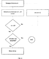
- FIG. 3 shows a flowchart of a data acquisition method.
- the actuator is used to rotate the array 6 relative to the breast 36 while retaining the breast in position.
- the acquisition process is then repeated with the antenna array 6 in the new configuration.
- the processor 4 may record the relative difference between the measured phase and amplitude of the transmitted signal as compared to the phase and amplitude of the scattered signal, recorded as a complex number (having real and imaginary parts).
- the signal detected at each antenna 16 is affected by scattering arising from objects within the imaged volume (i.e. the breast 36).
- tumours can generate significant reflections as they exhibit much higher dielectric properties than adipose and connective tissues due to their significant water content and so can be identified in the acquired data.
- Figure 4 shows a flowchart illustrating the various processing steps of the present invention.
- the method begins at a data acquisition step 41.
- This step corresponds, in this arrangement, to the acquisition method described with respect to Figure 3 .
- the acquired data may be used at a data reconstruction step 42 to construct an image of the internal structure of the breast.
- the Data reconstruction may be performed using Phased Array (frequency domain), Delay and Sum (DAS - time domain) techniques or any other suitable technique, such as 3D Fourier Transformation, Back Projection, etc. From this, the processor 4 is able to identify (possibly, with additional user input or confirmation) a region of interest (if present) in which a possible tumour or other pathology may exist.
- the reconstructed data may be subject to some calibration in order to remove components of the signals resulting from background noise, at step 43.
- a set of measurements may be taken while the imaging volume (e.g. the interior of the cup 30) is filled with a fluid medium matching the dielectric permittivity of the cup 30 and the layer of dielectric constant controlled fluid in gap 31.
- This signal can then be corrected for in (e.g. subtracted from) the reconstructed data to calibrate and remove components of the signals which do not relate to the surface of the object (as reflections off the surface of the matching medium will be small or non-existent).
- the reconstructed image will be in the form of an array of voxels corresponding to respective volumes within the breast, wherein each voxel has an intensity value that is indicative of the internal structure of the breast in the region in question.
- the processor generates intensity data that includes a set of intensity values for a three-dimensional data array of voxel elements and histogram data representing the voxel frequency density distribution for the intensity values. This may be done based on the reconstructed data representing an image of the internal structure of the breast. In such an arrangement, the processor will parse through the reconstructed data and determine, for each intensity value in the entire range of intensity values in the data, the number of voxels having the intensity value in question. The voxel frequency density can then be plotted against the corresponding intensity values (or "bins") to give a voxel frequency density distribution across the entire range of intensity values in the reconstructed data.
- the processor proceeds to step 45, where a parameter value is derived from the intensity values and the histogram data.
- the processor may be configured to determine the parameter value by calculating an area under the voxel frequency density curve.
- the processor is configured to determine the parameter value for only the voxels having intensity values falling within a range corresponding to the highest 35% of intensity values for the overall image.
- ranges may be selected. For example, the highest 5%, 10%, 15%, 20%, 25%, 30%, 35%, 40%, 45%, 50% or 55% could be used (or any value in between, or any higher value).
- the processor compares the area parameter value against a pre-determined reference value at step 46 of Figure 4 .
- the comparison includes determining whether the area value is above or below the pre-determined reference value.
- the breast is characterised as being comprised mainly of dense tissue, at step 47, and the processor provides an indication of such.
- the breast is characterised as being comprised mainly of fatty tissue, at step 47, and the processor provides an indication of such.
- Figure 5 is a schematic illustration of a histogram 50 of intensity data for a three-dimensional array of voxel elements. As can be seen, the histogram 50 shows a curve 51 of voxel frequency density across the entire range of intensity values in the reconstructed data.
- Figure 5 also shows a region of interest in the voxel frequency density curve corresponding to the highest 35% of intensity values for the overall image, which will be the subject of the parameter value determination.
- Figure 6 is an example plot 60 showing the results of performing the method of the present invention for five cases, each represented by an x on the plot. If the determined area value for a given case is less than the pre-determined reference value (i.e. below line 61 in Figure 6 ), the sample for that case will be characterised as being dense. An example of a patient falling into this category is given by the point labelled 63. On the other hand, if the determined area value for a given case is greater than the pre-determined reference value (i.e. above line 65 in Figure 6 ), the sample for that case will be characterised as being fatty. An example of a patient falling into this category is given by the point labelled 62.
- the pre-determined reference value i.e. below line 61 in Figure 6
- the present invention was used for a pool of cases that were pre-characterised according to size into three different classifications, small, medium and large, and for which a single reference value was determined in order to characterise the cases as being either dense or not.
- the present invention was used for a pool of 114 cases which were characterised beforehand as being large (i.e. falling within the large classification described above) and either fatty or dense.
- Table 1 shows the known distribution between fatty and dense tissue for the sample cases, determined from another imaging technique of known accuracy.
- Table 1 - showing the known distribution between fatty and dense tissue for 114 sample cases pre-characterised as being large. Size Fatty Dense Total L 50 64 114
- the method of the present invention was then performed for each case in a manner as described above with respect to Figure 6 , and by determining a parameter value corresponding to an area under a histogram curve.
- the density information may be generated from the raw data without generating an image of the breast 36.
- the density information may be provided separately in a standalone test where there is no cause for scanning the breast 36 for suspicious lesions.
- the system may therefore be embodied as a density measurement apparatus or meter which may or may not have the capability of imaging the breast.
- the present invention may serve as a useful pre-screening tool to identify the patient's risk score based on the breast density. This could be used to determine the screening frequency for the patient or other preventative measures based on the density assessment.
- the system may be simplified from that described above.
- the system may use a single antenna which serves to transmit and receive the microwave signal or a pair of antennas which transmit and receive.
Landscapes
- Health & Medical Sciences (AREA)
- Life Sciences & Earth Sciences (AREA)
- Engineering & Computer Science (AREA)
- Physics & Mathematics (AREA)
- Public Health (AREA)
- Medical Informatics (AREA)
- Veterinary Medicine (AREA)
- General Health & Medical Sciences (AREA)
- Animal Behavior & Ethology (AREA)
- Surgery (AREA)
- Molecular Biology (AREA)
- Biophysics (AREA)
- Pathology (AREA)
- Biomedical Technology (AREA)
- Heart & Thoracic Surgery (AREA)
- Artificial Intelligence (AREA)
- Evolutionary Computation (AREA)
- Mathematical Physics (AREA)
- Signal Processing (AREA)
- Psychiatry (AREA)
- Physiology (AREA)
- Computer Vision & Pattern Recognition (AREA)
- Fuzzy Systems (AREA)
- Gynecology & Obstetrics (AREA)
- Reproductive Health (AREA)
- Nuclear Medicine, Radiotherapy & Molecular Imaging (AREA)
- Radiology & Medical Imaging (AREA)
- Apparatus For Radiation Diagnosis (AREA)
- Ultra Sonic Daignosis Equipment (AREA)
Priority Applications (1)
| Application Number | Priority Date | Filing Date | Title |
|---|---|---|---|
| EP17195569.3A EP3466321A1 (de) | 2017-10-09 | 2017-10-09 | Brustdichtemessgerät und -verfahren |
Applications Claiming Priority (1)
| Application Number | Priority Date | Filing Date | Title |
|---|---|---|---|
| EP17195569.3A EP3466321A1 (de) | 2017-10-09 | 2017-10-09 | Brustdichtemessgerät und -verfahren |
Publications (1)
| Publication Number | Publication Date |
|---|---|
| EP3466321A1 true EP3466321A1 (de) | 2019-04-10 |
Family
ID=60083779
Family Applications (1)
| Application Number | Title | Priority Date | Filing Date |
|---|---|---|---|
| EP17195569.3A Withdrawn EP3466321A1 (de) | 2017-10-09 | 2017-10-09 | Brustdichtemessgerät und -verfahren |
Country Status (1)
| Country | Link |
|---|---|
| EP (1) | EP3466321A1 (de) |
Cited By (1)
| Publication number | Priority date | Publication date | Assignee | Title |
|---|---|---|---|---|
| MA57766B1 (fr) * | 2022-09-02 | 2024-08-30 | Université Mohammed V - RABAT | Système intelligent pour la Détection du Cancer du Sein par Technique Radiofréquence |
Citations (4)
| Publication number | Priority date | Publication date | Assignee | Title |
|---|---|---|---|---|
| US20060058606A1 (en) * | 2004-09-15 | 2006-03-16 | Davis Shakti K | Microwave-based examination using hypothesis testing |
| US20090024026A9 (en) * | 2004-09-10 | 2009-01-22 | Simpkin Ray A | Imaging system |
| WO2009060181A1 (en) | 2007-11-05 | 2009-05-14 | Micrima Limited | Antenna for investigating structure of human or animal |
| WO2014124304A1 (en) * | 2013-02-07 | 2014-08-14 | The Tructees Of Dartmouth College | System and method using precious-metal nanoparticle contrast agent for microwave medical imaging |
-
2017
- 2017-10-09 EP EP17195569.3A patent/EP3466321A1/de not_active Withdrawn
Patent Citations (4)
| Publication number | Priority date | Publication date | Assignee | Title |
|---|---|---|---|---|
| US20090024026A9 (en) * | 2004-09-10 | 2009-01-22 | Simpkin Ray A | Imaging system |
| US20060058606A1 (en) * | 2004-09-15 | 2006-03-16 | Davis Shakti K | Microwave-based examination using hypothesis testing |
| WO2009060181A1 (en) | 2007-11-05 | 2009-05-14 | Micrima Limited | Antenna for investigating structure of human or animal |
| WO2014124304A1 (en) * | 2013-02-07 | 2014-08-14 | The Tructees Of Dartmouth College | System and method using precious-metal nanoparticle contrast agent for microwave medical imaging |
Cited By (1)
| Publication number | Priority date | Publication date | Assignee | Title |
|---|---|---|---|---|
| MA57766B1 (fr) * | 2022-09-02 | 2024-08-30 | Université Mohammed V - RABAT | Système intelligent pour la Détection du Cancer du Sein par Technique Radiofréquence |
Similar Documents
| Publication | Publication Date | Title |
|---|---|---|
| Porter et al. | A wearable microwave antenna array for time-domain breast tumor screening | |
| EP3806721B1 (de) | Verfahren und system zur bestimmung des fraktionierten fettgehaltes von gewebe | |
| US8325877B2 (en) | Multi-modality volumetric data acquisition and imaging | |
| Wenkel et al. | Automated breast ultrasound: lesion detection and BI-RADS™ classification–a pilot study | |
| Sak et al. | Using speed of sound imaging to characterize breast density | |
| US20100014738A1 (en) | Method and system for breast cancer screening | |
| US20050107693A1 (en) | Tissue sensing adaptive radar imaging for breast tumor detection | |
| EP0694282A2 (de) | Nachweis und Darstellung von Brustkrebs durch elektromagnetische Millimeterwellen | |
| EP2234539B1 (de) | Radarsystem mit synthetischer Apertur | |
| WO2003045248A2 (en) | Calibration of tissue densities in computerized tomography | |
| Opieliński et al. | Imaging results of multi-modal ultrasound computerized tomography system designed for breast diagnosis | |
| JP2005193017A (ja) | 乳房患部分類の方法及びシステム | |
| Fasoula et al. | Pilot patient study with the Wavelia Microwave Breast Imaging system for breast cancer detection: Clinical feasibility and identified technical challenges | |
| Barigou et al. | X-ray micro-computed tomography for resolving food microstructures | |
| Opieliński et al. | Ultrasound transmission tomography imaging of structure of breast elastography phantom compared to US, CT and MRI | |
| Duric et al. | In-vivo imaging results with ultrasound tomography: Report on an ongoing study at the Karmanos Cancer Institute | |
| Mojabi et al. | Microwave imaging for breast density assessment: initial investigation | |
| EP3554339B1 (de) | System zur medizinischen bildgebung | |
| WO2018083492A1 (en) | A breast density meter and method | |
| Dia et al. | Ultrasound imaging of cortical bone: cortex geometry and measurement of porosity based on wave speed for bone remodeling estimation | |
| Weber et al. | Potential of non-contrast spiral breast CT to exploit lesion density and favor breast cancer detection: A pilot study | |
| Khairalseed et al. | Classification of thyroid nodules in H-scan ultrasound images using texture and prinicipal component analysis | |
| Kuwahara et al. | Large scale analysis of complex permittivity of breast cancer in microwave band | |
| Sani et al. | MammoWave breast imaging device: a procedure for device’s characterization via phantom measurements and subsequent clinical trials’ preliminary results | |
| Godinho et al. | Extracting dielectric properties for MRI-based phantoms for axillary microwave imaging device |
Legal Events
| Date | Code | Title | Description |
|---|---|---|---|
| PUAI | Public reference made under article 153(3) epc to a published international application that has entered the european phase |
Free format text: ORIGINAL CODE: 0009012 |
|
| STAA | Information on the status of an ep patent application or granted ep patent |
Free format text: STATUS: THE APPLICATION HAS BEEN PUBLISHED |
|
| AK | Designated contracting states |
Kind code of ref document: A1 Designated state(s): AL AT BE BG CH CY CZ DE DK EE ES FI FR GB GR HR HU IE IS IT LI LT LU LV MC MK MT NL NO PL PT RO RS SE SI SK SM TR |
|
| AX | Request for extension of the european patent |
Extension state: BA ME |
|
| STAA | Information on the status of an ep patent application or granted ep patent |
Free format text: STATUS: THE APPLICATION IS DEEMED TO BE WITHDRAWN |
|
| 18D | Application deemed to be withdrawn |
Effective date: 20191011 |