EP3554335B1 - Faserbasierte modenmischtechniken für chirurgische laserbeleuchtung - Google Patents
Faserbasierte modenmischtechniken für chirurgische laserbeleuchtung Download PDFInfo
- Publication number
- EP3554335B1 EP3554335B1 EP18704307.0A EP18704307A EP3554335B1 EP 3554335 B1 EP3554335 B1 EP 3554335B1 EP 18704307 A EP18704307 A EP 18704307A EP 3554335 B1 EP3554335 B1 EP 3554335B1
- Authority
- EP
- European Patent Office
- Prior art keywords
- optical fiber
- fiber
- vibrating
- light
- internal
- Prior art date
- Legal status (The legal status is an assumption and is not a legal conclusion. Google has not performed a legal analysis and makes no representation as to the accuracy of the status listed.)
- Active
Links
Images

Classifications
-
- A—HUMAN NECESSITIES
- A61—MEDICAL OR VETERINARY SCIENCE; HYGIENE
- A61B—DIAGNOSIS; SURGERY; IDENTIFICATION
- A61B90/00—Instruments, implements or accessories specially adapted for surgery or diagnosis and not covered by any of the groups A61B1/00 - A61B50/00, e.g. for luxation treatment or for protecting wound edges
- A61B90/30—Devices for illuminating a surgical field, the devices having an interrelation with other surgical devices or with a surgical procedure
-
- A—HUMAN NECESSITIES
- A61—MEDICAL OR VETERINARY SCIENCE; HYGIENE
- A61B—DIAGNOSIS; SURGERY; IDENTIFICATION
- A61B17/00—Surgical instruments, devices or methods
- A61B17/02—Surgical instruments, devices or methods for holding wounds open, e.g. retractors; Tractors
- A61B17/0231—Surgical instruments, devices or methods for holding wounds open, e.g. retractors; Tractors for eye surgery
-
- A—HUMAN NECESSITIES
- A61—MEDICAL OR VETERINARY SCIENCE; HYGIENE
- A61B—DIAGNOSIS; SURGERY; IDENTIFICATION
- A61B3/00—Apparatus for testing the eyes; Instruments for examining the eyes
- A61B3/0008—Apparatus for testing the eyes; Instruments for examining the eyes provided with illuminating means
-
- A—HUMAN NECESSITIES
- A61—MEDICAL OR VETERINARY SCIENCE; HYGIENE
- A61F—FILTERS IMPLANTABLE INTO BLOOD VESSELS; PROSTHESES; DEVICES PROVIDING PATENCY TO, OR PREVENTING COLLAPSING OF, TUBULAR STRUCTURES OF THE BODY, e.g. STENTS; ORTHOPAEDIC, NURSING OR CONTRACEPTIVE DEVICES; FOMENTATION; TREATMENT OR PROTECTION OF EYES OR EARS; BANDAGES, DRESSINGS OR ABSORBENT PADS; FIRST-AID KITS
- A61F9/00—Methods or devices for treatment of the eyes; Devices for putting in contact-lenses; Devices to correct squinting; Apparatus to guide the blind; Protective devices for the eyes, carried on the body or in the hand
- A61F9/007—Methods or devices for eye surgery
- A61F9/00736—Instruments for removal of intra-ocular material or intra-ocular injection, e.g. cataract instruments
-
- G—PHYSICS
- G02—OPTICS
- G02B—OPTICAL ELEMENTS, SYSTEMS OR APPARATUS
- G02B27/00—Optical systems or apparatus not provided for by any of the groups G02B1/00 - G02B26/00, G02B30/00
- G02B27/09—Beam shaping, e.g. changing the cross-sectional area, not otherwise provided for
- G02B27/0938—Using specific optical elements
- G02B27/0994—Fibers, light pipes
-
- G—PHYSICS
- G02—OPTICS
- G02B—OPTICAL ELEMENTS, SYSTEMS OR APPARATUS
- G02B6/00—Light guides; Structural details of arrangements comprising light guides and other optical elements, e.g. couplings
- G02B6/10—Light guides; Structural details of arrangements comprising light guides and other optical elements, e.g. couplings of the optical waveguide type
- G02B6/14—Mode converters
-
- A—HUMAN NECESSITIES
- A61—MEDICAL OR VETERINARY SCIENCE; HYGIENE
- A61B—DIAGNOSIS; SURGERY; IDENTIFICATION
- A61B18/00—Surgical instruments, devices or methods for transferring non-mechanical forms of energy to or from the body
- A61B18/18—Surgical instruments, devices or methods for transferring non-mechanical forms of energy to or from the body by applying electromagnetic radiation, e.g. microwaves
- A61B18/20—Surgical instruments, devices or methods for transferring non-mechanical forms of energy to or from the body by applying electromagnetic radiation, e.g. microwaves using laser
- A61B18/22—Surgical instruments, devices or methods for transferring non-mechanical forms of energy to or from the body by applying electromagnetic radiation, e.g. microwaves using laser the beam being directed along or through a flexible conduit, e.g. an optical fibre; Couplings or hand-pieces therefor
-
- A—HUMAN NECESSITIES
- A61—MEDICAL OR VETERINARY SCIENCE; HYGIENE
- A61B—DIAGNOSIS; SURGERY; IDENTIFICATION
- A61B90/00—Instruments, implements or accessories specially adapted for surgery or diagnosis and not covered by any of the groups A61B1/00 - A61B50/00, e.g. for luxation treatment or for protecting wound edges
- A61B90/30—Devices for illuminating a surgical field, the devices having an interrelation with other surgical devices or with a surgical procedure
- A61B2090/306—Devices for illuminating a surgical field, the devices having an interrelation with other surgical devices or with a surgical procedure using optical fibres
Definitions
- the present disclosure relates to surgical illumination, and more specifically, to fiber-based mode mixing techniques for surgical laser illumination.
- vitreoretinal surgery encompasses various delicate procedures involving internal portions of the eye, such as the vitreous humor and the retina. Different vitreoretinal surgical procedures are used, sometimes with lasers, to improve visual sensory performance in the treatment of many eye diseases, including epimacular membranes, diabetic retinopathy, vitreous hemorrhage, macular hole, detached retina, and complications of cataract surgery, among others.
- an ophthalmologist typically uses a surgical microscope to view the fundus through the cornea, while surgical instruments that penetrate the sclera may be introduced to perform any of a variety of different procedures.
- the patient typically lies supine under the surgical microscope during vitreoretinal surgery and a speculum is used to keep the eye exposed.
- the ophthalmologist has a given field of view of the fundus, which may vary from a narrow field of view to a wide field of view that can extend to peripheral regions of the fundus.
- an illumination source is typically introduced into the fundus to illuminate the area where the surgeon will be working.
- the illumination source is typically implemented as a surgical tool having an illuminator assembly that also penetrates the sclera and may be combined with other surgical tools.
- the use of optical fibers transmitting coherent light as illumination sources for surgery is desirable because of the high light intensity provided within very small physical dimensions available with optical fibers.
- a vibrating fiber mechanism may impart mechanical motion to a portion of the optical fiber to generate a homogeneous illumination field from a coherent light source.
- a disclosed method for surgical illumination includes projecting first light from a coherent light source into a first optical fiber, the coherent light source used for illumination of a patient during a surgery.
- the method may also include transmitting the first light from the first optical fiber to a fiber mode mixer device.
- the fiber mode mixer device may include an internal optical fiber receiving the first light and a vibrating fiber mechanism coupled to the internal optical fiber.
- the first light may be homogenized within the internal optical fiber by the vibrating fiber mechanism to generate second light output by the fiber mode mixer device.
- the method may further include transmitting the second light from the fiber mode mixer device to a second optical fiber.
- the second optical fiber may terminate in a third optical fiber that projects the second light onto the patient.
- the surgery may be an ophthalmic surgery
- the third optical fiber may project the second light into an eye of the patient.
- the coherent light source may be a monochromatic laser.
- the coherent light source may be a plurality of monochromatic lasers combined to generate the first light.
- the vibrating fiber mechanism may include a piezoelectric actuator mechanically coupled to the internal optical fiber.
- the vibrating fiber mechanism may include an electromagnetic actuator mechanically coupled to the internal optical fiber.
- the vibrating fiber mechanism may include a mechatronic actuator mechanically coupled to the internal optical fiber.
- the vibrating fiber mechanism may impart at least one of a reciprocal motion and a circular motion to at least a portion of the internal optical fiber.
- the vibrating fiber mechanism may impart a randomized motion to at least a portion of the internal optical fiber.
- the fiber mode mixer device may further include an input optical connector for connection to the first optical fiber, an output optical connector for connection to the second optical fiber, and a power source to power the vibrating fiber mechanism.
- the vibrating fiber mechanism may cause the internal optical fiber to reciprocate at a frequency greater than 30 Hz.
- a disclosed optical fiber homogenizer device is for surgical illumination.
- the optical fiber homogenizer device may include an input optical connector for connection to a first optical fiber transmitting first light from a coherent light source used for illumination of a patient during a surgery, an internal optical fiber coupled to the input connector to receive the first light.
- the optical fiber homogenizer device may also include a vibrating fiber mechanism mechanically coupled to the internal optical fiber.
- the first light may be homogenized within the internal optical fiber by the vibrating fiber mechanism to generate second light output by the optical fiber homogenizer device.
- the optical fiber homogenizer device may further include an output optical connector for connection to a second optical fiber, the output optical connector receiving the second light from the internal optical fiber.
- the second optical fiber may terminate in a third optical fiber that projects the second light onto the patient.
- the surgery may be an ophthalmic surgery
- the third optical fiber may project the second light into an eye of the patient.
- the coherent light source may be a monochromatic laser.
- the coherent light source may be a plurality of monochromatic lasers combined to generate the first light.
- the vibrating fiber mechanism may include a piezoelectric actuator mechanically coupled to the internal optical fiber.
- the vibrating fiber mechanism may include an electromagnetic actuator mechanically coupled to the internal optical fiber.
- the vibrating fiber mechanism may include a mechatronic actuator mechanically coupled to the internal optical fiber.
- the vibrating fiber mechanism may impart at least one of a reciprocal motion and a circular motion to at least a portion of the internal optical fiber.
- the vibrating fiber mechanism may impart a randomized motion to at least a portion of the internal optical fiber.
- the vibration fiber mechanism may cause the internal optical fiber to reciprocate at a frequency greater than 30 Hz.
- a hyphenated form of a reference numeral refers to a specific instance of an element and the un-hyphenated form of the reference numeral refers to the collective element.
- device ⁇ 12-1' refers to an instance of a device class, which may be referred to collectively as devices '12' and any one of which may be referred to generically as a device '12'.
- optical fibers and coherent light sources are desirable for surgical illumination because of the high light intensity provided within the very small physical dimensions of an optical fiber.
- surgical illumination sources may be used in various medical and surgical applications, one exemplary application is in eye surgery, such as for vitreoretinal surgery.
- the illumination source is typically implemented as a surgical tool having an illuminator assembly that penetrates the sclera and may be combined with other surgical tools.
- a very small diameter optical fiber may be used to project light into the fundus to illuminate surgical procedures performed within the eye.
- the very small diameter fiber for example having a fiber core of about 25-100 ⁇ m, is typically coupled to an optical fiber that couples proximally to a coherent light source, such as a laser source.
- a coherent light source such as a laser source.
- multi-mode optical fibers may be used to transmit coherent light into the eye for illumination.
- the modes may constructively and destructively interfere with each other during propagation within the optical fiber.
- an illumination field provided by the exiting light may appear inhomogeneous due to the inter-mode interference.
- the inter-mode interference may be highly sensitive to temperature, fiber strain, fiber motion, and may generally become quite noticeable to the human eye, since the inhomogeneous illumination field projects an undesired dynamic pattern, instead of a homogeneous illumination field projecting uniform background light. Because the inhomogeneous illumination field appears as different regions of different colored light that may be dynamic, the inhomogeneous illumination field may be poorly suited for surgical illumination.
- the inhomogeneous illumination field is observed with monochromatic laser sources, or combinations of monochromatic laser sources in some implementations.
- the monochromatic laser sources may exhibit fewer modes and, thus, a lesser degree of mode mixing within the optical fiber that enables homogenization of the coherent light into a desired homogeneous illumination field.
- various surgical tools such as endoilluminators or surgical tools with combined illumination, the use of smaller fiber diameters carrying high light intensity becomes increasingly desirable.
- optical fibers may exhibit fewer modes and less mode mixing, and may be particularly subject to the inhomogeneous illumination field.
- the fiber-based mode mixing techniques for surgical laser illumination disclosed herein may provide a homogeneous illumination field for surgical illumination using optical fibers to transmit coherent light.
- the fiber-based mode mixing techniques for surgical laser illumination disclosed herein may be used with relatively short and relatively small diameter optical fibers.
- the fiber-based mode mixing techniques for surgical laser illumination disclosed herein may be used with optical fibers having a glass core.
- the fiber-based mode mixing techniques for surgical laser illumination disclosed herein may be implemented at a light source for surgical illumination.
- the fiber-based mode mixing techniques for surgical laser illumination disclosed herein may be implemented as an optical device that can be coupled to an optical fiber providing surgical illumination from a coherent light source.
- the fiber-based mode mixing techniques for surgical laser illumination disclosed herein may be used for illumination of a patient's eye during ophthalmic surgery, such as vitreoretinal surgery.
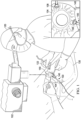
- FIGURE 1 One manner in which an illumination assembly 100 may be used is illustrated in FIGURE 1 , in which a surgeon 120 is performing an ophthalmic surgery on an eye 104 of a patient 130 using a surgical tool 122.
- the eye 104 has been exposed using a speculum 140 and a contact lens 150 is held in place on the eye 104 and visually aligned with a surgical microscope 102 to facilitate visualization of inner structures of the eye 104.
- the surgeon 120 is using the surgical tool 122 to perform surgery on inner structures of the eye 104.
- the surgical tool 122 when the surgical tool 122 is a vitrectomy probe, then the surgeon 120 may be using the surgical tool 122 to remove the clear, gel-like vitreous that normally fills the interior of the eye 104, taking care to remove substantially only the vitreous, while avoiding interaction with nearby eye structures, such as the retina, that are extremely sensitive to any mechanical action.
- the ability of the surgeon to clearly view the fundus is facilitated by a homogenous illumination field that is provided by illumination assembly 100.
- surgical tool 122 may by any of a variety of handheld surgical tools.
- illumination assembly 100 may be integrated within surgical tool 122 to provide illumination without having to use a secondary illumination tool.
- illuminator assembly 100 may include a means for fiber-based mode mixing for surgical laser illumination, as described in further detail below. Accordingly, illuminator assembly 100 may be used to project coherent light into the eye 104 using an optical fiber to transmit the light to project a homogenous illumination field (not visible in FIGURE 1 ) into the fundus.
- illuminator assembly 100 may be made without departing from the scope of the disclosure.
- the components and elements of surgical illuminator assembly 100, as described herein, may be integrated or separated according to particular applications.
- Illuminator assembly 100 may be implemented using more, fewer, or different components in some embodiments.
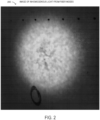
- FIGURE 2 illustrates an image 200 of inhomogeneous light from fiber modes.
- Image 200 depicts coherent light from an optical fiber projected onto a screen that is oriented oblique to the page.
- the depicted screen has extraneous annotations written in black ink above and below an inhomogeneous illumination field.
- the inhomogeneous illumination field in image 200 results from insufficient mode mixing within the optical fiber.
- the inhomogeneous illumination field in image 200 may exhibit intensity variations up to about 500%, which may be dynamic in many applications and usage scenarios, which is undesirable for surgical illumination, as explained previously.
- the inhomogeneous illumination field in image 200 may be immediately converted into a homogeneous illumination field, such as a substantially uniform intensity illumination field (not shown) by applying the techniques for mode mixing disclosed herein.
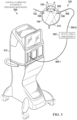
- FIGURE 3 a depiction of an embodiment of a surgical illumination system 300 is shown.
- surgical illumination system 300 may be used in the ophthalmic surgery on the eye 104 shown in FIGURE 1 .
- FIGURE 3 is a schematic illustration and is not drawn to scale or perspective.
- a cross-sectional view of the eye 104 is shown, enabling a view of various elements described above with respect to FIGURE 1 .
- contact lens 120 is shown providing a relatively wide angle view of the fundus of the eye 104, while two scleral ports 108 penetrate the sclera of the eye 104.
- a surgical tool 122 is shown penetrating one scleral port 108, while illumination assembly penetrates another scleral port 108.
- a homogeneous illumination field 310 is projected into the eye 104 by illuminator assembly 100.
- illuminator assembly 100 terminates distally with an optical fiber portion 308, which may be exposed to project light into the eye.
- Optical fiber portion 308 is coupled to an external optical fiber 304.
- optical fiber portion 308 may be a distal portion of external optical fiber 304 itself.
- Optical fiber 304 is shown having a first section of optical fiber 304-1 that extends from a surgical console 312 to an optical fiber homogenizer 302, and a second section of optical fiber 304-2 that extends from optical fiber homogenizer 302 to optical fiber 308.
- second section of optical fiber 304-2 is shown passing through a hand piece 306, which may include a sheath or tube around optical fiber 304-2 to enable cannulation at scleral port 108.
- optical fiber homogenizer 302 may apply fiber-based mode mixing techniques for surgical laser illumination, as disclosed herein. Specifically, optical fiber homogenizer 302 may apply mechanical movement or vibration to an optical fiber (not visible in FIGURE 3 ) in order to perform mode mixing and to homogenize the second light transmitted by optical fiber 304-2. In this manner, optical fiber homogenizer 302 provides homogeneous illumination field 310 in the eye 104 during surgery. Optical fiber homogenizer 302 may include optical connectors for connection to optical fibers 304-1 and 304-2, respectively. In some embodiments, optical fiber homogenizer 302 may be implemented within or integrated with surgical console 312, which may also include a coherent light source (not visible) to generate homogeneous illumination field 310. Surgical console 312 may provide various other equipment and functionality, such as driver equipment for surgical tool 122, and a user interface for data operations and image processing. Further internal details of optical fiber homogenizer 302 are described below with respect to FIGURE 4 .
- FIGURE 4 is a schematic illustration and is not drawn to scale or perspective.
- elements included within optical fiber homogenizer 302 are shown schematically.
- optical fiber homogenizer 302 may be implemented as an optical device, for example having an enclosure (not shown) to house the components illustrated in FIGURE 4 .
- optical fiber homogenizer 302 is shown having input optical connector 402 for connecting to optical fiber 304-1, as well as having output optical connector 406 for connecting to optical fiber 304-2.
- input optical connector 402 and output optical connector 406 may be releasable connectors (not shown) that mate with corresponding connectors attached to optical fibers 304-1 and 304-2.
- input optical connector 402 and output optical connector 406 may be fixed connectors.
- input optical connector 402, output optical connector 406, and a fiber mode mixer device 404 are situated on a fixed surface 436, which may represent a base of a housing (not shown) which may enclose optical fiber homogenizer 302.
- Input optical connector 402 may receive first light 400-1, which may experience insufficient mode mixing in optical fiber 304-1 after being transmitted from a coherent light source (not shown).
- the coherent light source may be a monochromatic laser, or a combination of monochromatic lasers that have been combined to generate first light 400-1.
- first light 400-1 may include light from different frequencies (i.e., colors).
- internal optical fiber 408 is coupled to fiber mode mixer device 404 by an attachment 438.
- a length of internal optical fiber 408 may vary and may be adjusted according to desired physical dimensions of optical fiber homogenizer 302.
- Attachment 438 may represent any type of mechanical attachment or fixture or member to couple to internal optical fiber 408.
- attachment 438 may include a clamp to attach externally to a portion of internal optical fiber 408.
- Fiber mode mixer device 404 includes a vibrating fiber mechanism comprised of mechanical components for moving or vibrating attachment 438, to which fiber mode mixer device 404 is fixed.
- the vibrating fiber mechanism may include any of a variety of mechanical actuators for generating motion of attachment 438, and thereby imparting motion to internal optical fiber 408, which is not otherwise connected to fixed surface 436.
- mechanical components or actuators included in fiber mode mixer device 404 may encompass rotating motors, linear motors, piezoelectric actuators, pneumatic actuators, hydraulic actuators, electromagnetic actuators, and mechatronic actuators, among various different combinations.
- the vibrating fiber mechanism may enable vibration, rotation, translation, or a combination thereof. Accordingly, the vibrating fiber mechanism may impart at least one of a reciprocal motion and a circular motion to at least a portion of internal optical fiber 408. In some embodiments, the vibrating fiber mechanism may impart a randomized motion to internal optical fiber 408.
- Electromagnetic actuators may include various actuators with magnets or magnet windings (electromagnets) that are electronically controlled.
- Mechatronic actuators may include various combinations of electronic and mechanical systems or components, such as integrated robotic drives.
- fiber mode mixer device 404 is coupled externally to internal optical fiber 408, a high degree of precision in the motion imparted to internal optical fiber 408 may be superfluous, and a lesser degree of precision may be suitable for the desired mode mixing effect to homogenize second light 400-2 that exits internal optical fiber 408 to optical fiber 304-2 via output optical connector 406.
- the fiber mode mixer device 404 reciprocates, rotates or oscillates at a frequency to cause motion that is not visible to the human eye, such as at a frequency of about 30 Hz or greater. In this manner, fiber mode mixer device 404 causes mode mixing within internal optical fiber 408 to generate homogeneous illumination field 310 that appears uniform to the human eye.
- power source 410 may provide power to the mechanical components included with fiber mode mixer device 404.
- power source 410 may represent an internal power source to optical fiber homogenizer 302, such as a battery to enable remote operation.
- power source 410 may represent an external power source, such as a connector for line power or direct current from an external power supply (not shown).
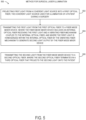
- Method 500 for fiber-based mode mixing techniques for surgical laser illumination, as described herein, is depicted in flowchart form. It is noted that certain operations described in method 500 may be optional or may be rearranged in different embodiments. Method 500 may be performed using illumination assembly 100 and optical fiber homogenizer 302, as described herein.
- Method 500 may begin, at step 502, by projecting first light from a coherent light source into a first optical fiber, the coherent light source used for illumination of a patient during a surgery.
- the first light is transmitted from the first optical fiber to a fiber mode mixer device, where the fiber mode mixer device includes an internal optical fiber receiving the first light and a vibrating fiber mechanism coupled to the internal optical fiber, and where the first light is homogenized within the internal optical fiber by the vibrating fiber mechanism to generate second light output by the fiber mode mixer device.
- the second light is transmitted from the fiber mode mixer device to a second optical fiber, where the second optical fiber terminates in a third optical fiber that projects the second light onto the patient.
- fiber-based mode mixing techniques may be used to homogenize different modes in an optical fiber used for surgical illumination.
- a vibrating fiber mechanism may impart mechanical motion to a portion of the optical fiber to generate a homogeneous illumination field from a coherent light source.
Landscapes
- Health & Medical Sciences (AREA)
- Life Sciences & Earth Sciences (AREA)
- Surgery (AREA)
- Physics & Mathematics (AREA)
- Ophthalmology & Optometry (AREA)
- Engineering & Computer Science (AREA)
- Heart & Thoracic Surgery (AREA)
- Biomedical Technology (AREA)
- Animal Behavior & Ethology (AREA)
- General Health & Medical Sciences (AREA)
- Public Health (AREA)
- Veterinary Medicine (AREA)
- Nuclear Medicine, Radiotherapy & Molecular Imaging (AREA)
- Medical Informatics (AREA)
- Molecular Biology (AREA)
- General Physics & Mathematics (AREA)
- Optics & Photonics (AREA)
- Vascular Medicine (AREA)
- Biophysics (AREA)
- Pathology (AREA)
- Oral & Maxillofacial Surgery (AREA)
- Laser Surgery Devices (AREA)
Claims (13)
- Homogenisatorvorrichtung (302) für optische Faser, die ausgestaltet ist, um faserbasiertes Modenmischen für chirurgische Beleuchtung bereitzustellen, wobei die Homogenisatorvorrichtung für optische Faser umfasst:einen optischen Eingangsverbinder (402) zum Verbinden mit einer ersten optischen Faser (304-1), die erstes Licht von einer kohärenten Lichtquelle überträgt, die zur Beleuchtung eines Patienten während eines chirurgischen Eingriffs verwendet wird;eine interne optische Faser (408), die an den Eingangsverbinder gekoppelt ist, um das erste Licht (400-1) zu empfangen;eine Fasermodenmischervorrichtung (404), die einen vibrierenden Fasermechanismus einschließt, der mechanisch an die interne optische Faser (408) gekoppelt ist, wobei das erste Licht innerhalb der internen optischen Faser (408) durch den vibrierenden Fasermechanismus homogenisiert wird, um durch die Homogenisatorvorrichtung für optische Faser zweite Lichtausgabe (400-2) zu generieren; undeinen optischen Ausgangsverbinder (405) zur Verbindung mit einer zweiten optischen Faser (304-2), wobei der optische Ausgangsverbinder das zweite Licht (400-2) von der internen optischen Faser (408) empfängt, wobei die zweite optische Faser (304-2) in einer dritten optischen Faser (308) endet, die das zweite Licht auf den Patienten projiziert;wobei der vibrierende Fasermechanismus bewirkt, dass sich die interne optische Faser mit einer Frequenz größer als 30 Hz hin und her bewegt.
- Homogenisatorvorrichtung für optische Faser nach Anspruch 1, wobei der chirurgische Eingriff ein ophthalmischer chirurgischer Eingriff ist und die dritte optische Faser (308) das zweite Licht in ein Auge des Patienten projiziert.
- Homogenisatorvorrichtung für optische Faser nach Anspruch 1, wobei die kohärente Lichtquelle ein monochromatischer Laser ist.
- Homogenisatorvorrichtung für optische Faser nach Anspruch 1, wobei die kohärente Lichtquelle eine Vielzahl von monochromatischen Lasern ist, die kombiniert sind, um das erste Licht zu generieren.
- Homogenisatorvorrichtung für optische Faser nach Anspruch 1, wobei der vibrierende Fasermechanismus (404) einen piezoelektrischen Aktuator einschließt, der mechanisch an die interne optische Faser (408) gekoppelt ist.
- Homogenisatorvorrichtung für optische Faser nach Anspruch 1, wobei der vibrierende Fasermechanismus (404) einen elektromagnetischen Aktuator einschließt, der mechanisch an die interne optische Faser (408) gekoppelt ist.
- Homogenisatorvorrichtung für optische Faser nach Anspruch 1, wobei der vibrierende Fasermechanismus (404) einen mechatronischen Aktuator einschließt, der mechanisch an die interne optische Faser (408) gekoppelt ist.
- Homogenisatorvorrichtung für optische Faser nach Anspruch 1, wobei der vibrierende Fasermechanismus (404) mindestens einem Anteil der internen optischen Faser (408) mindestens eine von einer Hin- und Herbewegung und einer Kreisbewegung verleiht.
- Homogenisatorvorrichtung für optische Faser nach Anspruch 1, wobei der vibrierende Fasermechanismus (404) mindestens einem Anteil der internen optischen Faser (408) eine randomisierte Bewegung verleiht.
- Verfahren (500) zum faserbasierten Modenmischen für eine chirurgische Laserbeleuchtung, wobei das Verfahren unter Verwendung einer Homogenisatorvorrichtung (302) für optische Faser durchgeführt wird, umfassend:einen optischen Eingangsverbinder (402) zur Verbindung mit der ersten optischen Faser;eine Fasermodenmischervorrichtung (404), die einen vibrierenden Fasermechanismus einschließt;einen optischen Ausgangsverbinder (405) zur Verbindung mit der zweiten optischen Faser; undeine Leistungsquelle (410) zur Leistungsversorgung des vibrierenden Fasermechanismus,wobei das Verfahren umfasst:Projizieren von erstem Licht aus einer kohärenten Lichtquelle in eine erste optische Faser (304-1), wobei die kohärente Lichtquelle (100) zur Beleuchtung eines Patienten während eines chirurgischen Eingriffs verwendet wird;Übermitteln des ersten Lichts aus der ersten optischen Faser (304-2) zu der Fasermodenmischervorrichtung (404), wobei die Fasermodenmischervorrichtung (404) eine interne optische Faser (408), die das erste Licht empfängt, und einen vibrierenden Fasermechanismus einschließt, der an die interne optische Faser (408) gekoppelt ist, wobei das erste Licht (400-1) innerhalb der internen optischen Faser (408) durch den vibrierenden Fasermechanismus homogenisiert wird, um durch die Fasermodenmischervorrichtung (404) zweite Lichtausgabe (400-2) zu generieren; undÜbermitteln des zweiten Lichts (400-2) aus der Fasermodenmischervorrichtung (404) an eine zweite optische Faser (304-2), wobei die zweite optische Faser in einer dritten optischen Faser (308) endet, die das zweite Licht auf den Patienten projiziert; undwobei des Weiteren der vibrierende Fasermechanismus bewirkt, dass sich die interne optische Faser mit einer Frequenz größer als 30 Hz hin und her bewegt.
- Verfahren nach Anspruch 10, wobei der chirurgische Eingriff ein ophthalmischer chirurgischer Eingriff ist und die dritte optische Faser das zweite Licht in ein Auge des Patienten projiziert.
- Verfahren nach Anspruch 10, wobei die kohärente Lichtquelle gemäß einem der folgenden vorgesehen ist:(i) wobei die kohärente Lichtquelle ein monochromatischer Laser ist;(ii) wobei die kohärente Lichtquelle eine Vielzahl von monochromatischen Lasern ist, die kombiniert sind, um das erste Licht zu generieren.
- Verfahren nach Anspruch 10, wobei der vibrierende Fasermechanismus gemäß einem oder mehreren der folgenden vorgesehen ist:(i) wobei der vibrierende Fasermechanismus einen piezoelektrischen Aktuator einschließt, der mechanisch an die interne optische Faser gekoppelt ist;(ii) wobei der vibrierende Fasermechanismus einen elektromagnetischen Aktuator einschließt, der mechanisch an die interne optische Faser gekoppelt ist;(iii) wobei der vibrierende Fasermechanismus einen mechatronischen Aktuator einschließt, der mechanisch an die interne optische Faser gekoppelt ist;(iv) wobei der vibrierende Fasermechanismus mindestens einem Anteil der internen optischen Faser mindestens eine von einer Hin- und Herbewegung und einer Kreisbewegung verleiht;(v) wobei der vibrierende Fasermechanismus mindestens einem Anteil der internen optischen Faser eine randomisierte Bewegung verleiht.
Applications Claiming Priority (2)
| Application Number | Priority Date | Filing Date | Title |
|---|---|---|---|
| US201762453744P | 2017-02-02 | 2017-02-02 | |
| PCT/IB2018/050529 WO2018142262A1 (en) | 2017-02-02 | 2018-01-29 | Fiber-based mode mixing techniques for surgical laser illumination |
Publications (2)
| Publication Number | Publication Date |
|---|---|
| EP3554335A1 EP3554335A1 (de) | 2019-10-23 |
| EP3554335B1 true EP3554335B1 (de) | 2024-01-03 |
Family
ID=61189490
Family Applications (1)
| Application Number | Title | Priority Date | Filing Date |
|---|---|---|---|
| EP18704307.0A Active EP3554335B1 (de) | 2017-02-02 | 2018-01-29 | Faserbasierte modenmischtechniken für chirurgische laserbeleuchtung |
Country Status (8)
| Country | Link |
|---|---|
| US (1) | US10687912B2 (de) |
| EP (1) | EP3554335B1 (de) |
| JP (1) | JP6826206B2 (de) |
| CN (1) | CN110300540B (de) |
| AU (1) | AU2018215520C1 (de) |
| CA (1) | CA3051535A1 (de) |
| ES (1) | ES2972850T3 (de) |
| WO (1) | WO2018142262A1 (de) |
Families Citing this family (6)
| Publication number | Priority date | Publication date | Assignee | Title |
|---|---|---|---|---|
| EP3554335B1 (de) | 2017-02-02 | 2024-01-03 | Alcon Inc. | Faserbasierte modenmischtechniken für chirurgische laserbeleuchtung |
| CN110300538A (zh) | 2017-02-02 | 2019-10-01 | 诺华股份有限公司 | 用于混合模式手术激光照明的聚焦光学器件 |
| WO2018142270A1 (en) | 2017-02-02 | 2018-08-09 | Novartis Ag | Frequency-based mode mixing for surgical laser illumination |
| US11065077B2 (en) | 2017-02-02 | 2021-07-20 | Alcon Inc. | Mechanical optics for mixed mode surgical laser illumination |
| AU2018215574A1 (en) | 2017-02-02 | 2019-08-01 | Alcon Inc. | Pixelated array optics for mixed mode surgical laser illumination |
| WO2022190076A1 (en) | 2021-03-12 | 2022-09-15 | Stryker European Operations Limited | Neurosurgical methods and systems for detecting and removing tumorous tissue |
Family Cites Families (53)
| Publication number | Priority date | Publication date | Assignee | Title |
|---|---|---|---|---|
| US5395362A (en) * | 1992-01-14 | 1995-03-07 | Summit Technology | Methods and apparatus for distributing laser radiation |
| US6299307B1 (en) | 1997-10-10 | 2001-10-09 | Visx, Incorporated | Eye tracking device for laser eye surgery using corneal margin detection |
| JP4054222B2 (ja) | 2002-06-05 | 2008-02-27 | オリンパス株式会社 | 内視鏡装置用光源装置 |
| US20040151008A1 (en) | 2003-02-03 | 2004-08-05 | Artsyukhovich Alexander N. | Variable spot size illuminators with enhanced homogeneity and parfocality |
| JP2005046247A (ja) * | 2003-07-31 | 2005-02-24 | Topcon Corp | レーザ手術装置 |
| US20080269731A1 (en) | 2003-11-19 | 2008-10-30 | Casimir Andrew Swinger | Method and apparatus applying patient-verified prescription of high order aberrations |
| US7339737B2 (en) | 2004-04-23 | 2008-03-04 | Microvision, Inc. | Beam multiplier that can be used as an exit-pupil expander and related system and method |
| US7298970B2 (en) | 2004-08-30 | 2007-11-20 | Eastman Kodak Company | Zoom flash with variable focus lens |
| WO2007007388A1 (ja) * | 2005-07-11 | 2007-01-18 | Mitsubishi Denki Kabushiki Kaisha | 照明装置 |
| US20070047059A1 (en) | 2005-08-31 | 2007-03-01 | Howard P G | Illumination path shifting |
| US20080055698A1 (en) | 2006-05-23 | 2008-03-06 | Samsung Electro-Mechanics Co., Ltd. | Optical modulator and optical modulator module for reducing laser speckle |
| JP2008152116A (ja) | 2006-12-19 | 2008-07-03 | Lasertec Corp | 照明装置、及び照明方法 |
| US7499624B2 (en) | 2007-03-16 | 2009-03-03 | Alcon, Inc. | Ophthalmic Endoilluminator with Variable-Wedge Rotating-Disk Beam Attenuator |
| US7444057B2 (en) | 2007-03-16 | 2008-10-28 | Alcon, Inc. | Variable-wedge rotating-disk beam attenuator for ophthalmic endoilluminator |
| US20080246919A1 (en) | 2007-04-09 | 2008-10-09 | Ron Smith | Ophthalmic Endoilluminator with Hybrid Lens |
| DE102007041439A1 (de) | 2007-08-28 | 2009-03-05 | Carl Zeiss Surgical Gmbh | Sekundäre Lichtquelle |
| US7959297B2 (en) | 2008-05-15 | 2011-06-14 | Eastman Kodak Company | Uniform speckle reduced laser projection using spatial and temporal mixing |
| US8498512B2 (en) | 2008-12-22 | 2013-07-30 | Bausch & Lomb Incorporated | Controlling beam intensity in an ophthalmic fiber optic illumination system using rotatable plate arrays |
| GB2467181B (en) * | 2009-01-27 | 2014-03-05 | Optyka Ltd | Speckle removal for a laser scanning projector |
| DE102009024941A1 (de) * | 2009-06-09 | 2010-12-23 | Carl Zeiss Surgical Gmbh | Beleuchtungsvorrichtung und medizinisch-optisches Beobachtungsgerät |
| KR101083677B1 (ko) * | 2009-07-27 | 2011-11-16 | 연세대학교 산학협력단 | 광선의 스페클 콘트라스트 제어장치 |
| US20110144745A1 (en) | 2009-12-11 | 2011-06-16 | Martin Michael Mcculloch | Ophthalmic endoillumination system |
| US8944647B2 (en) | 2010-09-02 | 2015-02-03 | Optotune Ag | Illumination source with variable divergence |
| US8902506B2 (en) | 2010-09-30 | 2014-12-02 | Panasonic Corporation | Laser speckle reduction element |
| US20120203075A1 (en) * | 2011-02-08 | 2012-08-09 | Christopher Horvath | White coherent laser light launched into nano fibers for surgical illumination |
| WO2012122677A1 (zh) * | 2011-03-17 | 2012-09-20 | Chen Chih-Hsiao | 激光投影系统的光斑抑制装置及其抑制方法 |
| US20130144278A1 (en) | 2011-12-06 | 2013-06-06 | Michael Papac | Devices and Methods for Multispot Scanning |
| WO2013085736A1 (en) | 2011-12-09 | 2013-06-13 | Alcon Research, Ltd. | Devices and methods for reconfigurable multispot scanning |
| US20130158393A1 (en) | 2011-12-19 | 2013-06-20 | Michael Papac | Concentric Drive Scanning Probe |
| US20130158392A1 (en) | 2011-12-19 | 2013-06-20 | Michael Papac | Reciprocating Drive Optical Scanner for Surgical Endoprobes |
| JP5879285B2 (ja) | 2012-02-29 | 2016-03-08 | 富士フイルム株式会社 | 音響波検出用プローブおよび光音響計測装置 |
| JP6040578B2 (ja) | 2012-06-02 | 2016-12-07 | 株式会社ニデック | 眼科用レーザ手術装置 |
| US10502870B2 (en) * | 2012-10-04 | 2019-12-10 | North Inc. | Optical assembly |
| US20150277137A1 (en) | 2012-10-17 | 2015-10-01 | Optotune Ag | Speckle free laser projection |
| WO2014153132A2 (en) * | 2013-03-14 | 2014-09-25 | Pivot Medical, Inc. | Method and apparatus for reconstructing a hip joint, including the provision and use of a novel arthroscopic debridement template for assisting in the treatment of cam-type femoroacetabular impingement |
| WO2014145465A2 (en) | 2013-03-15 | 2014-09-18 | Liolios Thomas | Eye safe laser illumination in ophthalmic surgeries |
| US9323049B2 (en) | 2013-05-07 | 2016-04-26 | Novartis Ag | Forward scanning optical probes with one or more rotating components |
| EP2884637A1 (de) | 2013-12-10 | 2015-06-17 | Optotune AG | Optische Vorrichtung zur Verringerung von Speckle-Verzerrung |
| CN103799961B (zh) | 2014-03-11 | 2015-09-09 | 洪德飞 | 小动物腹腔镜活体光学分子成像系统及方法 |
| EP2945005A1 (de) * | 2014-05-16 | 2015-11-18 | Optotune AG | Laserprojektionssystem zur Verringerung von Granulatrauschen |
| US10238543B2 (en) | 2014-10-29 | 2019-03-26 | Novartis Ag | Vitrectomy probe with an optical fiber scanner |
| US11504192B2 (en) * | 2014-10-30 | 2022-11-22 | Cilag Gmbh International | Method of hub communication with surgical instrument systems |
| EP3035110A1 (de) * | 2014-12-18 | 2016-06-22 | Optotune AG | Optisches System zur Vermeidung von Speckle-Mustern |
| NZ773847A (en) * | 2015-03-16 | 2022-07-01 | Magic Leap Inc | Methods and systems for diagnosing and treating health ailments |
| US10058247B2 (en) * | 2015-05-20 | 2018-08-28 | Comprehensive Telemedicine | Multipurpose diagnostic examination apparatus and system |
| CA2958766C (en) * | 2016-02-25 | 2018-01-02 | Synaptive Medical (Barbados) Inc. | System and method for scope based depth map acquisition |
| WO2018142270A1 (en) | 2017-02-02 | 2018-08-09 | Novartis Ag | Frequency-based mode mixing for surgical laser illumination |
| CN110300538A (zh) | 2017-02-02 | 2019-10-01 | 诺华股份有限公司 | 用于混合模式手术激光照明的聚焦光学器件 |
| EP3554335B1 (de) | 2017-02-02 | 2024-01-03 | Alcon Inc. | Faserbasierte modenmischtechniken für chirurgische laserbeleuchtung |
| US11065077B2 (en) | 2017-02-02 | 2021-07-20 | Alcon Inc. | Mechanical optics for mixed mode surgical laser illumination |
| AU2018215574A1 (en) | 2017-02-02 | 2019-08-01 | Alcon Inc. | Pixelated array optics for mixed mode surgical laser illumination |
| US11179175B2 (en) * | 2017-12-28 | 2021-11-23 | Cilag Gmbh International | Controlling an ultrasonic surgical instrument according to tissue location |
| WO2019197993A1 (en) * | 2018-04-11 | 2019-10-17 | Alcon Inc. | Illuminating ophthalmic endoprobe |
-
2018
- 2018-01-29 EP EP18704307.0A patent/EP3554335B1/de active Active
- 2018-01-29 US US15/882,758 patent/US10687912B2/en active Active
- 2018-01-29 JP JP2019541440A patent/JP6826206B2/ja active Active
- 2018-01-29 CN CN201880012291.2A patent/CN110300540B/zh active Active
- 2018-01-29 CA CA3051535A patent/CA3051535A1/en active Pending
- 2018-01-29 WO PCT/IB2018/050529 patent/WO2018142262A1/en not_active Ceased
- 2018-01-29 AU AU2018215520A patent/AU2018215520C1/en active Active
- 2018-01-29 ES ES18704307T patent/ES2972850T3/es active Active
Also Published As
| Publication number | Publication date |
|---|---|
| CN110300540B (zh) | 2022-01-04 |
| AU2018215520C1 (en) | 2023-11-23 |
| WO2018142262A1 (en) | 2018-08-09 |
| ES2972850T3 (es) | 2024-06-17 |
| EP3554335A1 (de) | 2019-10-23 |
| US20180214237A1 (en) | 2018-08-02 |
| JP6826206B2 (ja) | 2021-02-03 |
| CN110300540A (zh) | 2019-10-01 |
| AU2018215520A1 (en) | 2019-08-01 |
| CA3051535A1 (en) | 2018-08-09 |
| AU2018215520B2 (en) | 2023-04-06 |
| US10687912B2 (en) | 2020-06-23 |
| JP2020505990A (ja) | 2020-02-27 |
Similar Documents
| Publication | Publication Date | Title |
|---|---|---|
| EP3554335B1 (de) | Faserbasierte modenmischtechniken für chirurgische laserbeleuchtung | |
| US10779905B2 (en) | Focusing optics for mixed mode surgical laser illumination | |
| US11006822B2 (en) | Pixelated array optics for mixed mode surgical laser illumination | |
| US11065077B2 (en) | Mechanical optics for mixed mode surgical laser illumination | |
| JP6619428B2 (ja) | 内部照明された手術プローブ | |
| US10398312B2 (en) | Frequency-based mode mixing for surgical laser illumination | |
| US10729461B2 (en) | Illuminated infusion cannula | |
| RU2603427C2 (ru) | Комбинированный хирургический эндозонд для оптической когерентной томографии, подсветки или фотокоагуляции | |
| CN103260540B (zh) | 使用公共光源的光学相干性层析成像和照明 | |
| EP3009064A1 (de) | Optische tomografievorrichtung | |
| US11931297B2 (en) | Glare reduction endoilluminators |
Legal Events
| Date | Code | Title | Description |
|---|---|---|---|
| STAA | Information on the status of an ep patent application or granted ep patent |
Free format text: STATUS: UNKNOWN |
|
| STAA | Information on the status of an ep patent application or granted ep patent |
Free format text: STATUS: THE INTERNATIONAL PUBLICATION HAS BEEN MADE |
|
| PUAI | Public reference made under article 153(3) epc to a published international application that has entered the european phase |
Free format text: ORIGINAL CODE: 0009012 |
|
| STAA | Information on the status of an ep patent application or granted ep patent |
Free format text: STATUS: REQUEST FOR EXAMINATION WAS MADE |
|
| 17P | Request for examination filed |
Effective date: 20190716 |
|
| AK | Designated contracting states |
Kind code of ref document: A1 Designated state(s): AL AT BE BG CH CY CZ DE DK EE ES FI FR GB GR HR HU IE IS IT LI LT LU LV MC MK MT NL NO PL PT RO RS SE SI SK SM TR |
|
| AX | Request for extension of the european patent |
Extension state: BA ME |
|
| DAV | Request for validation of the european patent (deleted) | ||
| DAX | Request for extension of the european patent (deleted) | ||
| RAP1 | Party data changed (applicant data changed or rights of an application transferred) |
Owner name: ALCON INC. |
|
| STAA | Information on the status of an ep patent application or granted ep patent |
Free format text: STATUS: EXAMINATION IS IN PROGRESS |
|
| 17Q | First examination report despatched |
Effective date: 20220217 |
|
| P01 | Opt-out of the competence of the unified patent court (upc) registered |
Effective date: 20230507 |
|
| REG | Reference to a national code |
Ref legal event code: R079 Free format text: PREVIOUS MAIN CLASS: A61B0003000000 Ipc: A61B0090300000 Ref country code: DE Ref legal event code: R079 Ref document number: 602018063550 Country of ref document: DE Free format text: PREVIOUS MAIN CLASS: A61B0003000000 Ipc: A61B0090300000 |
|
| GRAP | Despatch of communication of intention to grant a patent |
Free format text: ORIGINAL CODE: EPIDOSNIGR1 |
|
| STAA | Information on the status of an ep patent application or granted ep patent |
Free format text: STATUS: GRANT OF PATENT IS INTENDED |
|
| RIC1 | Information provided on ipc code assigned before grant |
Ipc: A61B 3/00 20060101ALI20230711BHEP Ipc: G02B 6/14 20060101ALI20230711BHEP Ipc: A61B 18/22 20060101ALI20230711BHEP Ipc: G02B 27/09 20060101ALI20230711BHEP Ipc: A61B 90/30 20160101AFI20230711BHEP |
|
| INTG | Intention to grant announced |
Effective date: 20230801 |
|
| GRAS | Grant fee paid |
Free format text: ORIGINAL CODE: EPIDOSNIGR3 |
|
| GRAA | (expected) grant |
Free format text: ORIGINAL CODE: 0009210 |
|
| STAA | Information on the status of an ep patent application or granted ep patent |
Free format text: STATUS: THE PATENT HAS BEEN GRANTED |
|
| AK | Designated contracting states |
Kind code of ref document: B1 Designated state(s): AL AT BE BG CH CY CZ DE DK EE ES FI FR GB GR HR HU IE IS IT LI LT LU LV MC MK MT NL NO PL PT RO RS SE SI SK SM TR |
|
| REG | Reference to a national code |
Ref country code: GB Ref legal event code: FG4D |
|
| REG | Reference to a national code |
Ref country code: DE Ref legal event code: R096 Ref document number: 602018063550 Country of ref document: DE |
|
| REG | Reference to a national code |
Ref country code: CH Ref legal event code: EP |
|
| REG | Reference to a national code |
Ref country code: IE Ref legal event code: FG4D |
|
| REG | Reference to a national code |
Ref country code: NL Ref legal event code: FP |
|
| REG | Reference to a national code |
Ref country code: LT Ref legal event code: MG9D |
|
| PGFP | Annual fee paid to national office [announced via postgrant information from national office to epo] |
Ref country code: CH Payment date: 20240202 Year of fee payment: 7 |
|
| REG | Reference to a national code |
Ref country code: AT Ref legal event code: MK05 Ref document number: 1646031 Country of ref document: AT Kind code of ref document: T Effective date: 20240103 |
|
| REG | Reference to a national code |
Ref country code: ES Ref legal event code: FG2A Ref document number: 2972850 Country of ref document: ES Kind code of ref document: T3 Effective date: 20240617 |
|
| PG25 | Lapsed in a contracting state [announced via postgrant information from national office to epo] |
Ref country code: IS Free format text: LAPSE BECAUSE OF FAILURE TO SUBMIT A TRANSLATION OF THE DESCRIPTION OR TO PAY THE FEE WITHIN THE PRESCRIBED TIME-LIMIT Effective date: 20240503 |
|
| PG25 | Lapsed in a contracting state [announced via postgrant information from national office to epo] |
Ref country code: LT Free format text: LAPSE BECAUSE OF FAILURE TO SUBMIT A TRANSLATION OF THE DESCRIPTION OR TO PAY THE FEE WITHIN THE PRESCRIBED TIME-LIMIT Effective date: 20240103 |
|
| PG25 | Lapsed in a contracting state [announced via postgrant information from national office to epo] |
Ref country code: GR Free format text: LAPSE BECAUSE OF FAILURE TO SUBMIT A TRANSLATION OF THE DESCRIPTION OR TO PAY THE FEE WITHIN THE PRESCRIBED TIME-LIMIT Effective date: 20240404 |
|
| PG25 | Lapsed in a contracting state [announced via postgrant information from national office to epo] |
Ref country code: RS Free format text: LAPSE BECAUSE OF FAILURE TO SUBMIT A TRANSLATION OF THE DESCRIPTION OR TO PAY THE FEE WITHIN THE PRESCRIBED TIME-LIMIT Effective date: 20240403 Ref country code: HR Free format text: LAPSE BECAUSE OF FAILURE TO SUBMIT A TRANSLATION OF THE DESCRIPTION OR TO PAY THE FEE WITHIN THE PRESCRIBED TIME-LIMIT Effective date: 20240103 |
|
| PG25 | Lapsed in a contracting state [announced via postgrant information from national office to epo] |
Ref country code: AT Free format text: LAPSE BECAUSE OF FAILURE TO SUBMIT A TRANSLATION OF THE DESCRIPTION OR TO PAY THE FEE WITHIN THE PRESCRIBED TIME-LIMIT Effective date: 20240103 Ref country code: CZ Free format text: LAPSE BECAUSE OF FAILURE TO SUBMIT A TRANSLATION OF THE DESCRIPTION OR TO PAY THE FEE WITHIN THE PRESCRIBED TIME-LIMIT Effective date: 20240103 |
|
| PG25 | Lapsed in a contracting state [announced via postgrant information from national office to epo] |
Ref country code: RS Free format text: LAPSE BECAUSE OF FAILURE TO SUBMIT A TRANSLATION OF THE DESCRIPTION OR TO PAY THE FEE WITHIN THE PRESCRIBED TIME-LIMIT Effective date: 20240403 Ref country code: NO Free format text: LAPSE BECAUSE OF FAILURE TO SUBMIT A TRANSLATION OF THE DESCRIPTION OR TO PAY THE FEE WITHIN THE PRESCRIBED TIME-LIMIT Effective date: 20240403 Ref country code: LT Free format text: LAPSE BECAUSE OF FAILURE TO SUBMIT A TRANSLATION OF THE DESCRIPTION OR TO PAY THE FEE WITHIN THE PRESCRIBED TIME-LIMIT Effective date: 20240103 Ref country code: IS Free format text: LAPSE BECAUSE OF FAILURE TO SUBMIT A TRANSLATION OF THE DESCRIPTION OR TO PAY THE FEE WITHIN THE PRESCRIBED TIME-LIMIT Effective date: 20240503 Ref country code: HR Free format text: LAPSE BECAUSE OF FAILURE TO SUBMIT A TRANSLATION OF THE DESCRIPTION OR TO PAY THE FEE WITHIN THE PRESCRIBED TIME-LIMIT Effective date: 20240103 Ref country code: GR Free format text: LAPSE BECAUSE OF FAILURE TO SUBMIT A TRANSLATION OF THE DESCRIPTION OR TO PAY THE FEE WITHIN THE PRESCRIBED TIME-LIMIT Effective date: 20240404 Ref country code: CZ Free format text: LAPSE BECAUSE OF FAILURE TO SUBMIT A TRANSLATION OF THE DESCRIPTION OR TO PAY THE FEE WITHIN THE PRESCRIBED TIME-LIMIT Effective date: 20240103 Ref country code: BG Free format text: LAPSE BECAUSE OF FAILURE TO SUBMIT A TRANSLATION OF THE DESCRIPTION OR TO PAY THE FEE WITHIN THE PRESCRIBED TIME-LIMIT Effective date: 20240103 Ref country code: AT Free format text: LAPSE BECAUSE OF FAILURE TO SUBMIT A TRANSLATION OF THE DESCRIPTION OR TO PAY THE FEE WITHIN THE PRESCRIBED TIME-LIMIT Effective date: 20240103 |
|
| PG25 | Lapsed in a contracting state [announced via postgrant information from national office to epo] |
Ref country code: PL Free format text: LAPSE BECAUSE OF FAILURE TO SUBMIT A TRANSLATION OF THE DESCRIPTION OR TO PAY THE FEE WITHIN THE PRESCRIBED TIME-LIMIT Effective date: 20240103 Ref country code: PT Free format text: LAPSE BECAUSE OF FAILURE TO SUBMIT A TRANSLATION OF THE DESCRIPTION OR TO PAY THE FEE WITHIN THE PRESCRIBED TIME-LIMIT Effective date: 20240503 |
|
| PG25 | Lapsed in a contracting state [announced via postgrant information from national office to epo] |
Ref country code: SE Free format text: LAPSE BECAUSE OF FAILURE TO SUBMIT A TRANSLATION OF THE DESCRIPTION OR TO PAY THE FEE WITHIN THE PRESCRIBED TIME-LIMIT Effective date: 20240103 Ref country code: PT Free format text: LAPSE BECAUSE OF FAILURE TO SUBMIT A TRANSLATION OF THE DESCRIPTION OR TO PAY THE FEE WITHIN THE PRESCRIBED TIME-LIMIT Effective date: 20240503 Ref country code: PL Free format text: LAPSE BECAUSE OF FAILURE TO SUBMIT A TRANSLATION OF THE DESCRIPTION OR TO PAY THE FEE WITHIN THE PRESCRIBED TIME-LIMIT Effective date: 20240103 Ref country code: LV Free format text: LAPSE BECAUSE OF FAILURE TO SUBMIT A TRANSLATION OF THE DESCRIPTION OR TO PAY THE FEE WITHIN THE PRESCRIBED TIME-LIMIT Effective date: 20240103 |
|
| PG25 | Lapsed in a contracting state [announced via postgrant information from national office to epo] |
Ref country code: LU Free format text: LAPSE BECAUSE OF NON-PAYMENT OF DUE FEES Effective date: 20240129 |
|
| PG25 | Lapsed in a contracting state [announced via postgrant information from national office to epo] |
Ref country code: LU Free format text: LAPSE BECAUSE OF NON-PAYMENT OF DUE FEES Effective date: 20240129 |
|
| REG | Reference to a national code |
Ref country code: DE Ref legal event code: R097 Ref document number: 602018063550 Country of ref document: DE |
|
| PG25 | Lapsed in a contracting state [announced via postgrant information from national office to epo] |
Ref country code: DK Free format text: LAPSE BECAUSE OF FAILURE TO SUBMIT A TRANSLATION OF THE DESCRIPTION OR TO PAY THE FEE WITHIN THE PRESCRIBED TIME-LIMIT Effective date: 20240103 |
|
| PG25 | Lapsed in a contracting state [announced via postgrant information from national office to epo] |
Ref country code: SM Free format text: LAPSE BECAUSE OF FAILURE TO SUBMIT A TRANSLATION OF THE DESCRIPTION OR TO PAY THE FEE WITHIN THE PRESCRIBED TIME-LIMIT Effective date: 20240103 |
|
| PG25 | Lapsed in a contracting state [announced via postgrant information from national office to epo] |
Ref country code: BE Free format text: LAPSE BECAUSE OF NON-PAYMENT OF DUE FEES Effective date: 20240131 |
|
| PG25 | Lapsed in a contracting state [announced via postgrant information from national office to epo] |
Ref country code: EE Free format text: LAPSE BECAUSE OF FAILURE TO SUBMIT A TRANSLATION OF THE DESCRIPTION OR TO PAY THE FEE WITHIN THE PRESCRIBED TIME-LIMIT Effective date: 20240103 |
|
| PG25 | Lapsed in a contracting state [announced via postgrant information from national office to epo] |
Ref country code: SK Free format text: LAPSE BECAUSE OF FAILURE TO SUBMIT A TRANSLATION OF THE DESCRIPTION OR TO PAY THE FEE WITHIN THE PRESCRIBED TIME-LIMIT Effective date: 20240103 |
|
| PG25 | Lapsed in a contracting state [announced via postgrant information from national office to epo] |
Ref country code: SM Free format text: LAPSE BECAUSE OF FAILURE TO SUBMIT A TRANSLATION OF THE DESCRIPTION OR TO PAY THE FEE WITHIN THE PRESCRIBED TIME-LIMIT Effective date: 20240103 Ref country code: SK Free format text: LAPSE BECAUSE OF FAILURE TO SUBMIT A TRANSLATION OF THE DESCRIPTION OR TO PAY THE FEE WITHIN THE PRESCRIBED TIME-LIMIT Effective date: 20240103 Ref country code: RO Free format text: LAPSE BECAUSE OF FAILURE TO SUBMIT A TRANSLATION OF THE DESCRIPTION OR TO PAY THE FEE WITHIN THE PRESCRIBED TIME-LIMIT Effective date: 20240103 Ref country code: EE Free format text: LAPSE BECAUSE OF FAILURE TO SUBMIT A TRANSLATION OF THE DESCRIPTION OR TO PAY THE FEE WITHIN THE PRESCRIBED TIME-LIMIT Effective date: 20240103 Ref country code: DK Free format text: LAPSE BECAUSE OF FAILURE TO SUBMIT A TRANSLATION OF THE DESCRIPTION OR TO PAY THE FEE WITHIN THE PRESCRIBED TIME-LIMIT Effective date: 20240103 Ref country code: BE Free format text: LAPSE BECAUSE OF NON-PAYMENT OF DUE FEES Effective date: 20240131 |
|
| REG | Reference to a national code |
Ref country code: BE Ref legal event code: MM Effective date: 20240131 |
|
| PLBE | No opposition filed within time limit |
Free format text: ORIGINAL CODE: 0009261 |
|
| STAA | Information on the status of an ep patent application or granted ep patent |
Free format text: STATUS: NO OPPOSITION FILED WITHIN TIME LIMIT |
|
| PG25 | Lapsed in a contracting state [announced via postgrant information from national office to epo] |
Ref country code: MC Free format text: LAPSE BECAUSE OF FAILURE TO SUBMIT A TRANSLATION OF THE DESCRIPTION OR TO PAY THE FEE WITHIN THE PRESCRIBED TIME-LIMIT Effective date: 20240103 |
|
| PG25 | Lapsed in a contracting state [announced via postgrant information from national office to epo] |
Ref country code: MC Free format text: LAPSE BECAUSE OF FAILURE TO SUBMIT A TRANSLATION OF THE DESCRIPTION OR TO PAY THE FEE WITHIN THE PRESCRIBED TIME-LIMIT Effective date: 20240103 |
|
| 26N | No opposition filed |
Effective date: 20241007 |
|
| PG25 | Lapsed in a contracting state [announced via postgrant information from national office to epo] |
Ref country code: IE Free format text: LAPSE BECAUSE OF NON-PAYMENT OF DUE FEES Effective date: 20240129 |
|
| PG25 | Lapsed in a contracting state [announced via postgrant information from national office to epo] |
Ref country code: IE Free format text: LAPSE BECAUSE OF NON-PAYMENT OF DUE FEES Effective date: 20240129 |
|
| PGFP | Annual fee paid to national office [announced via postgrant information from national office to epo] |
Ref country code: DE Payment date: 20241217 Year of fee payment: 8 |
|
| PGFP | Annual fee paid to national office [announced via postgrant information from national office to epo] |
Ref country code: ES Payment date: 20250207 Year of fee payment: 8 |
|
| PG25 | Lapsed in a contracting state [announced via postgrant information from national office to epo] |
Ref country code: SI Free format text: LAPSE BECAUSE OF FAILURE TO SUBMIT A TRANSLATION OF THE DESCRIPTION OR TO PAY THE FEE WITHIN THE PRESCRIBED TIME-LIMIT Effective date: 20240103 |
|
| PGFP | Annual fee paid to national office [announced via postgrant information from national office to epo] |
Ref country code: IT Payment date: 20241230 Year of fee payment: 8 |
|
| PG25 | Lapsed in a contracting state [announced via postgrant information from national office to epo] |
Ref country code: CY Free format text: LAPSE BECAUSE OF FAILURE TO SUBMIT A TRANSLATION OF THE DESCRIPTION OR TO PAY THE FEE WITHIN THE PRESCRIBED TIME-LIMIT; INVALID AB INITIO Effective date: 20180129 |
|
| REG | Reference to a national code |
Ref country code: CH Ref legal event code: PL |
|
| PG25 | Lapsed in a contracting state [announced via postgrant information from national office to epo] |
Ref country code: HU Free format text: LAPSE BECAUSE OF FAILURE TO SUBMIT A TRANSLATION OF THE DESCRIPTION OR TO PAY THE FEE WITHIN THE PRESCRIBED TIME-LIMIT; INVALID AB INITIO Effective date: 20180129 |
|
| PG25 | Lapsed in a contracting state [announced via postgrant information from national office to epo] |
Ref country code: FI Free format text: LAPSE BECAUSE OF FAILURE TO SUBMIT A TRANSLATION OF THE DESCRIPTION OR TO PAY THE FEE WITHIN THE PRESCRIBED TIME-LIMIT Effective date: 20240103 |
|
| PG25 | Lapsed in a contracting state [announced via postgrant information from national office to epo] |
Ref country code: CH Free format text: LAPSE BECAUSE OF NON-PAYMENT OF DUE FEES Effective date: 20250131 |
|
| PG25 | Lapsed in a contracting state [announced via postgrant information from national office to epo] |
Ref country code: TR Free format text: LAPSE BECAUSE OF FAILURE TO SUBMIT A TRANSLATION OF THE DESCRIPTION OR TO PAY THE FEE WITHIN THE PRESCRIBED TIME-LIMIT Effective date: 20240103 |
|
| PGFP | Annual fee paid to national office [announced via postgrant information from national office to epo] |
Ref country code: GB Payment date: 20251218 Year of fee payment: 9 |
|
| PGFP | Annual fee paid to national office [announced via postgrant information from national office to epo] |
Ref country code: FR Payment date: 20251222 Year of fee payment: 9 Ref country code: NL Payment date: 20251225 Year of fee payment: 9 |