EP3554293B1 - Aerosolerzeugungssystem mit externer kartusche - Google Patents
Aerosolerzeugungssystem mit externer kartusche Download PDFInfo
- Publication number
- EP3554293B1 EP3554293B1 EP17816652.6A EP17816652A EP3554293B1 EP 3554293 B1 EP3554293 B1 EP 3554293B1 EP 17816652 A EP17816652 A EP 17816652A EP 3554293 B1 EP3554293 B1 EP 3554293B1
- Authority
- EP
- European Patent Office
- Prior art keywords
- aerosol
- cartridge
- generating device
- generating
- generating system
- Prior art date
- Legal status (The legal status is an assumption and is not a legal conclusion. Google has not performed a legal analysis and makes no representation as to the accuracy of the status listed.)
- Active
Links
Images


Classifications
-
- A—HUMAN NECESSITIES
- A24—TOBACCO; CIGARS; CIGARETTES; SIMULATED SMOKING DEVICES; SMOKERS' REQUISITES
- A24F—SMOKERS' REQUISITES; MATCH BOXES; SIMULATED SMOKING DEVICES
- A24F40/00—Electrically operated smoking devices; Component parts thereof; Manufacture thereof; Maintenance or testing thereof; Charging means specially adapted therefor
- A24F40/40—Constructional details, e.g. connection of cartridges and battery parts
- A24F40/42—Cartridges or containers for inhalable precursors
-
- A—HUMAN NECESSITIES
- A24—TOBACCO; CIGARS; CIGARETTES; SIMULATED SMOKING DEVICES; SMOKERS' REQUISITES
- A24F—SMOKERS' REQUISITES; MATCH BOXES; SIMULATED SMOKING DEVICES
- A24F47/00—Smokers' requisites not otherwise provided for
-
- A—HUMAN NECESSITIES
- A24—TOBACCO; CIGARS; CIGARETTES; SIMULATED SMOKING DEVICES; SMOKERS' REQUISITES
- A24F—SMOKERS' REQUISITES; MATCH BOXES; SIMULATED SMOKING DEVICES
- A24F40/00—Electrically operated smoking devices; Component parts thereof; Manufacture thereof; Maintenance or testing thereof; Charging means specially adapted therefor
- A24F40/30—Devices using two or more structurally separated inhalable precursors, e.g. using two liquid precursors in two cartridges
-
- A—HUMAN NECESSITIES
- A24—TOBACCO; CIGARS; CIGARETTES; SIMULATED SMOKING DEVICES; SMOKERS' REQUISITES
- A24B—MANUFACTURE OR PREPARATION OF TOBACCO FOR SMOKING OR CHEWING; TOBACCO; SNUFF
- A24B15/00—Chemical features or treatment of tobacco; Tobacco substitutes, e.g. in liquid form
- A24B15/10—Chemical features of tobacco products or tobacco substitutes
- A24B15/16—Chemical features of tobacco products or tobacco substitutes of tobacco substitutes
- A24B15/167—Chemical features of tobacco products or tobacco substitutes of tobacco substitutes in liquid or vaporisable form, e.g. liquid compositions for electronic cigarettes
-
- A—HUMAN NECESSITIES
- A24—TOBACCO; CIGARS; CIGARETTES; SIMULATED SMOKING DEVICES; SMOKERS' REQUISITES
- A24F—SMOKERS' REQUISITES; MATCH BOXES; SIMULATED SMOKING DEVICES
- A24F40/00—Electrically operated smoking devices; Component parts thereof; Manufacture thereof; Maintenance or testing thereof; Charging means specially adapted therefor
- A24F40/10—Devices using liquid inhalable precursors
-
- A—HUMAN NECESSITIES
- A24—TOBACCO; CIGARS; CIGARETTES; SIMULATED SMOKING DEVICES; SMOKERS' REQUISITES
- A24F—SMOKERS' REQUISITES; MATCH BOXES; SIMULATED SMOKING DEVICES
- A24F40/00—Electrically operated smoking devices; Component parts thereof; Manufacture thereof; Maintenance or testing thereof; Charging means specially adapted therefor
- A24F40/40—Constructional details, e.g. connection of cartridges and battery parts
- A24F40/46—Shape or structure of electric heating means
-
- A—HUMAN NECESSITIES
- A24—TOBACCO; CIGARS; CIGARETTES; SIMULATED SMOKING DEVICES; SMOKERS' REQUISITES
- A24F—SMOKERS' REQUISITES; MATCH BOXES; SIMULATED SMOKING DEVICES
- A24F40/00—Electrically operated smoking devices; Component parts thereof; Manufacture thereof; Maintenance or testing thereof; Charging means specially adapted therefor
- A24F40/40—Constructional details, e.g. connection of cartridges and battery parts
- A24F40/48—Fluid transfer means, e.g. pumps
- A24F40/485—Valves; Apertures
-
- A—HUMAN NECESSITIES
- A24—TOBACCO; CIGARS; CIGARETTES; SIMULATED SMOKING DEVICES; SMOKERS' REQUISITES
- A24F—SMOKERS' REQUISITES; MATCH BOXES; SIMULATED SMOKING DEVICES
- A24F40/00—Electrically operated smoking devices; Component parts thereof; Manufacture thereof; Maintenance or testing thereof; Charging means specially adapted therefor
- A24F40/50—Control or monitoring
-
- A—HUMAN NECESSITIES
- A24—TOBACCO; CIGARS; CIGARETTES; SIMULATED SMOKING DEVICES; SMOKERS' REQUISITES
- A24F—SMOKERS' REQUISITES; MATCH BOXES; SIMULATED SMOKING DEVICES
- A24F40/00—Electrically operated smoking devices; Component parts thereof; Manufacture thereof; Maintenance or testing thereof; Charging means specially adapted therefor
- A24F40/70—Manufacture
-
- A—HUMAN NECESSITIES
- A61—MEDICAL OR VETERINARY SCIENCE; HYGIENE
- A61M—DEVICES FOR INTRODUCING MEDIA INTO, OR ONTO, THE BODY; DEVICES FOR TRANSDUCING BODY MEDIA OR FOR TAKING MEDIA FROM THE BODY; DEVICES FOR PRODUCING OR ENDING SLEEP OR STUPOR
- A61M15/00—Inhalators
- A61M15/06—Inhaling appliances shaped like cigars, cigarettes or pipes
-
- H—ELECTRICITY
- H05—ELECTRIC TECHNIQUES NOT OTHERWISE PROVIDED FOR
- H05B—ELECTRIC HEATING; ELECTRIC LIGHT SOURCES NOT OTHERWISE PROVIDED FOR; CIRCUIT ARRANGEMENTS FOR ELECTRIC LIGHT SOURCES, IN GENERAL
- H05B3/00—Ohmic-resistance heating
- H05B3/10—Heating elements characterised by the composition or nature of the materials or by the arrangement of the conductor
- H05B3/12—Heating elements characterised by the composition or nature of the materials or by the arrangement of the conductor characterised by the composition or nature of the conductive material
-
- H—ELECTRICITY
- H05—ELECTRIC TECHNIQUES NOT OTHERWISE PROVIDED FOR
- H05B—ELECTRIC HEATING; ELECTRIC LIGHT SOURCES NOT OTHERWISE PROVIDED FOR; CIRCUIT ARRANGEMENTS FOR ELECTRIC LIGHT SOURCES, IN GENERAL
- H05B3/00—Ohmic-resistance heating
- H05B3/20—Heating elements having extended surface area substantially in a two-dimensional [2D] plane, e.g. plate-heater
- H05B3/22—Heating elements having extended surface area substantially in a two-dimensional [2D] plane, e.g. plate-heater non-flexible
- H05B3/24—Heating elements having extended surface area substantially in a two-dimensional [2D] plane, e.g. plate-heater non-flexible heating conductor being self-supporting
-
- H—ELECTRICITY
- H05—ELECTRIC TECHNIQUES NOT OTHERWISE PROVIDED FOR
- H05B—ELECTRIC HEATING; ELECTRIC LIGHT SOURCES NOT OTHERWISE PROVIDED FOR; CIRCUIT ARRANGEMENTS FOR ELECTRIC LIGHT SOURCES, IN GENERAL
- H05B3/00—Ohmic-resistance heating
- H05B3/40—Heating elements having the shape of rods or tubes
- H05B3/42—Heating elements having the shape of rods or tubes non-flexible
- H05B3/44—Heating elements having the shape of rods or tubes non-flexible heating conductor arranged within rods or tubes of insulating material
-
- A—HUMAN NECESSITIES
- A24—TOBACCO; CIGARS; CIGARETTES; SIMULATED SMOKING DEVICES; SMOKERS' REQUISITES
- A24F—SMOKERS' REQUISITES; MATCH BOXES; SIMULATED SMOKING DEVICES
- A24F40/00—Electrically operated smoking devices; Component parts thereof; Manufacture thereof; Maintenance or testing thereof; Charging means specially adapted therefor
- A24F40/20—Devices using solid inhalable precursors
Definitions
- the present invention relates to an aerosol-generating system comprising an aerosol-generating device and a cartridge configured to be received on the aerosol-generating device.
- the invention finds particular application as an electrically operated smoking system.
- Aerosol-generating system is an electrically operated smoking system.
- Known handheld electrically operated smoking systems typically comprise an aerosol-generating device comprising a battery, control electronics and an electric heater for heating an aerosol-forming substrate.
- the aerosol-forming substrate may be contained within part of the aerosol-generating device.
- the aerosol-generating device may comprise a liquid storage portion in which a liquid aerosol-forming substrate, such as a nicotine solution, is stored.
- a liquid aerosol-forming substrate such as a nicotine solution
- Such devices often referred to as 'e-cigarettes', typically contain sufficient liquid aerosol-forming substrate to provide a number of puffs equivalent to consuming multiple conventional cigarettes.
- US 2014/166029 A1 describes an e-cigarette comprising a battery section and a cartomizer, and various embodiments of a flavour enhancement that may be combined with the e-cigarette.
- the flavour enhancement is provided in the form of a tubular shell that is received within the cartomizer.
- the flavour enhancement is in the form of a tubular shell that is received over an external wall of the cartomizer.
- the wall of the cartomizer may be formed from a permeable material or have holes extending therethrough to allow a flavouring agent from tubular shell to diffuse through the cartomizer wall and into the airflow inside the cartomizer.
- some devices In an attempt to provide e-cigarette users with an experience that more closely simulates the experience of consuming a conventional cigarette some devices have attempted to combine an e-cigarette configuration with a tobacco-based substrate to impart a tobacco taste to the aerosol inhaled by the user. However, to accommodate the tobacco-based substrate, such devices are typically significantly larger than convention e-cigarettes.
- an aerosol-generating system as defined by claim 1, said system comprising a cartridge and an aerosol-generating device.
- the cartridge comprises a cartridge aerosol-forming substrate, the cartridge having an annular shape.
- the aerosol-generating device has a first end, a second end and a length extending between the first end and the second end.
- the aerosol-generating device comprises a liquid storage section comprising a liquid aerosol-forming substrate positioned within the liquid storage portion, and a first electric heater configured to heat liquid aerosol-forming substrate from the liquid storage section during use of the aerosol-generating system.
- the aerosol-generating device further comprises a power supply section comprising a power supply and a controller for controlling a supply of electrical power from the power supply to the first electric heater.
- the aerosol-generating device also comprises a device air inlet positioned between the first end and the second end of the device, and a device air outlet positioned at the second end of the device.
- the aerosol-generating device is configured to receive the cartridge on the aerosol-generating device so that the cartridge at least partially overlies the device air inlet.
- aerosol-forming substrate is used to describe a substrate capable of releasing volatile compounds, which can form an aerosol.
- the aerosols generated from aerosol-forming substrates of aerosol-generating systems according to the invention may be visible or invisible and may include vapours (for example, fine particles of substances, which are in a gaseous state, that are ordinarily liquid or solid at room temperature) as well as gases and liquid droplets of condensed vapours.
- Aerosol-generating systems provide an annular cartridge configured to be received on an aerosol-generating device so that the cartridge overlies a device air inlet. Therefore, in use, air is drawn into the aerosol-generating device through the cartridge.
- this arrangement eliminates the need for a cartridge-receiving cavity in the aerosol-generating device. Eliminating a cartridge-receiving cavity can facilitate an aerosol-generating device length that is similar to conventional e-cigarettes. Eliminating a cartridge-receiving cavity makes it easier for a user to engage and disengage the cartridge with the aerosol-generating device. In particular, the risk of a cartridge becoming stuck in a cartridge-receiving cavity is eliminated.
- this arrangement facilitates the use of an aerosol-generating device that is similar to conventional e-cigarettes, which may reduce or eliminate the need to modify existing devices.
- the aerosol-generating system is configured so that the cartridge is retained on the aerosol-generating device by an interference fit.
- An outer surface of the aerosol-generating device forms a flange against which the cartridge is received when the cartridge is received on the aerosol-generating device, wherein the device air inlet is positioned proximate the flange.
- providing a flange against which the cartridge is received may facilitate correct placement of the cartridge on the aerosol-generating device by a user.
- the device air inlet may be positioned on the flange so that an end of the cartridge abuts the device air inlet when the cartridge is received against the flange.
- the device air inlet may be positioned on the outer surface of the aerosol-generating device adjacent the flange so that an inner surface of the cartridge at least partially overlies the device air inlet when the cartridge is received against the flange.
- the liquid storage section is removable from the power supply section.
- this facilitates replacement of the liquid storage section (for example, when the liquid aerosol-generating substrate has been depleted) without replacement of the power supply section.
- the liquid storage section may be configured for removable attachment to the power supply section by at least one of an interference fit, a screw connection and a bayonet connection.
- the power supply section has a first end forming the first end of the aerosol-generating device and a second end, wherein the liquid storage section has a first end configured for removable attachment to the second end of the power supply section and a second end forming the second end of the aerosol-generating device.
- One of the first end of the liquid storage section and the second end of the power supply section forms the flange when the liquid storage section is attached to the power supply section.
- An outer dimension of the second end of the power supply section may be larger than an outer dimension of the first end of the liquid storage section.
- An outer dimension of the first end of the liquid storage section may be larger than an outer dimension of the second end of the power supply section.
- the aerosol-generating system may further comprise a second electric heater provided on an outer surface of the aerosol-generating device, wherein the second electric heater is positioned so that the cartridge at least partially overlies the second electric heater when the cartridge is received on the aerosol-generating device.
- the controller is configured to control a supply of electrical power from the power supply to the second electric heater when the cartridge is received on the aerosol-generating device.
- providing a second heater configured to heat the cartridge may facilitate the release of volatile compounds from the cartridge aerosol-forming substrate during use of the aerosol-generating system.
- the second heater may comprise a substantially annular heater extending around a portion of the outer surface of the aerosol-generating device.
- the second heater may comprise a plurality of discrete heaters positioned around a portion of the outer surface of the aerosol-generating device.
- the aerosol-generating system may further comprise a removable cover configured to receive at least a portion of the aerosol-generating device, wherein the removable cover is configured to overlie the cartridge when the cartridge is received on the aerosol-generating device and when the removable cover is engaged with the aerosol-generating device.
- the removable cover may protect the cartridge when the aerosol-generating system is handled by a user during use. Preventing a user touching the cartridge during use may be particularly desirable in embodiments in which the aerosol-generating system comprises a second heater configured to heat the cartridge.
- the removable cover in combination with the aerosol-generating device may provide the aerosol-generating system with at least one of a visual appearance and external dimensions that are substantially the same as a conventional e-cigarette.
- this may provide compatibility of the aerosol-generating system with existing accessories, such as a carry case.
- the removable cover has a substantially cylindrical shape.
- the removable cover may be substantially closed at one end.
- the removable cover may comprise a cover air outlet configured for fluid communication with the device air outlet when the removable cover is engaged with the aerosol-generating device.
- the cover air outlet is provided on the closed end.
- the removable cover may be comprise a cover air inlet configured for fluid communication with the cartridge when the cartridge is received on the aerosol-generating device and when the removable cover is engaged with the aerosol-generating device.
- a first end of the removable cover may be configured to abut the flange when the removable cover is engaged with the aerosol-generating device.
- this may facilitate correct placement of the removable cover on the aerosol-generating device by a user.
- the removable cover is configured to be retained on the aerosol-generating device by an interference fit.
- the cartridge may form a sleeve configured to slide onto a portion of the aerosol-generating device.
- the cartridge may be configured to be received between the liquid storage section and the power supply section.
- a connecting portion of one or both of the liquid storage section and the power supply section may extend through the cartridge when the cartridge is received on the aerosol-generating device.
- the cartridge may form an annular disc.
- the annular disc may be one of a ring shape, a split-ring shape, and a C-shape.
- a ring shape may prevent the cartridge becoming detached from the aerosol-generating device while the liquid storage section is attached to the power supply section.
- a split-ring shape may facilitate engagement of the cartridge with a connecting portion on the liquid storage section or the power supply section by allowing a small degree of expansion and contraction in the size of the ring.
- a C-shape may facilitate engagement and disengagement of the cartridge with the aerosol-generating device without separating the liquid storage section from the power supply section.
- the liquid storage section removable attaches to the power supply section by a screw connection
- engagement and disengagement of the cartridge with the aerosol-generating device may be facilitated by only partially unscrewing the liquid storage section from the power supply section.
- the cartridge may comprise a porous wrapper overlying at least a portion of the cartridge aerosol-forming substrate.
- the porous wrapper may substantially encapsulate the cartridge aerosol-forming substrate.
- the porous wrapper may comprise at least one of a woven material and a non-woven material.
- the porous wrapper may comprise a mesh.
- the porous wrapper may comprise a paper.
- providing a porous wrapper overlying at least a portion of the cartridge aerosol-forming substrate may retain the cartridge aerosol-forming substrate in the desired shape and allow air to flow through the cartridge during use.
- the cartridge may comprise a cartridge housing, wherein the cartridge aerosol-forming substrate is positioned within the cartridge housing.
- the cartridge housing comprises a cartridge air inlet and a cartridge air outlet.
- the cartridge is configured so that, when the cartridge is engaged with the aerosol-generating device, the cartridge air outlet overlies the device air inlet.
- Each of the cartridge and the aerosol-generating device may comprise one or more indicia to indicate to a user the rotational orientation of the cartridge with respect to the aerosol-generating device.
- this may assist a user in aligning the cartridge air outlet with the device air inlet.
- the cartridge housing may be formed from any suitable material or combination of materials. Suitable materials include, but are not limited to, aluminium, polyether ether ketone (PEEK), polyimides, such as Kapton®, polyethylene terephthalate (PET), polyethylene (PE), high-density polyethylene (HDPE), polypropylene (PP), polystyrene (PS), fluorinated ethylene propylene (FEP), polytetrafluoroethylene (PTFE), polyoxymethylene (POM), epoxy resins, polyurethane resins, vinyl resins, liquid crystal polymers (LCP) and modified LCPs, such as LCPs with graphite or glass fibres.
- PEEK polyether ether ketone
- polyimides such as Kapton®, polyethylene terephthalate (PET), polyethylene (PE), high-density polyethylene (HDPE), polypropylene (PP), polystyrene (PS), fluorinated ethylene propylene (FEP), polytetraflu
- the aerosol-generating system may comprise a removable wrapper enclosing the cartridge.
- the removable wrapper is removed from the cartridge prior to use of the cartridge with the aerosol-generating device.
- the removable wrapper comprises a non-porous material.
- the removable wrapper may comprise a polymeric material, such as a polymeric film.
- the removable wrapper may comprise a laminate of two or more different materials.
- the removable wrapper may comprise a metallised polymeric film.
- the first electric heater may be provided separately from both the liquid storage section and the power supply section, wherein the first electric heater is configured for removable attachment to at least one of the liquid storage section and the power supply section.
- the first electric heater may be provided integrally with one of the power supply section and the liquid storage section.
- the first electric heater and liquid storage section are provided together in a vaporiser section of the aerosol-generating device.
- the vaporiser section is configured for removable attachment to the power supply section.
- the cartridge aerosol-forming substrate may comprise a solid aerosol-forming substrate.
- the solid aerosol-forming substrate may comprise tobacco.
- the solid aerosol-forming substrate may comprise a tobacco-containing material containing volatile tobacco flavour compounds which are released from the substrate upon heating.
- the solid aerosol-forming substrate may comprise tobacco containing deprotonated nicotine.
- Deprotonating the nicotine within tobacco may advantageously increase the volatility of the nicotine.
- Nicotine may be deprotonated by subjecting the tobacco to an alkalising treatment.
- the solid aerosol-forming substrate may comprise a non-tobacco material.
- the solid aerosol-forming substrate may comprise tobacco-containing material and non-tobacco containing material.
- the solid aerosol-forming substrate may include at least one aerosol-former.
- aerosol-formers include, but are not limited to: polyhydric alcohols, such as propylene glycol, triethylene glycol, 1,3-butanediol and glycerine; esters of polyhydric alcohols, such as glycerol mono-, di- or triacetate; and aliphatic esters of mono-, di- or polycarboxylic acids, such as dimethyl dodecanedioate and dimethyl tetradecanedioate
- Preferred aerosol formers are polyhydric alcohols or mixtures thereof, such as propylene glycol, triethylene glycol, 1,3-butanediol and, most preferred, glycerine.
- the solid aerosol-forming substrate may comprise a single aerosol former.
- the solid aerosol-forming substrate may comprise a combination of two or more aerosol formers.
- the solid aerosol-forming substrate may have an aerosol former content of greater than 5 percent on a dry weight basis.
- the solid aerosol-forming substrate may have an aerosol former content of between approximately 5 percent and approximately 30 percent on a dry weight basis.
- the solid aerosol-forming substrate may have an aerosol former content of approximately 20 percent on a dry weight basis.
- the liquid aerosol-forming substrate of the liquid storage section may comprise a tobacco-containing material comprising volatile tobacco flavour compounds which are released from the liquid upon heating.
- the liquid aerosol-forming substrate may comprise a non-tobacco material.
- the liquid aerosol-forming substrate may include water, solvents, ethanol, plant extracts and natural or artificial flavours.
- the liquid aerosol-forming substrate comprises an aerosol former. Suitable aerosol formers include polyhydric alcohols or mixtures thereof, such as propylene glycol, triethylene glycol, 1,3-butanediol and glycerine.
- the liquid aerosol-forming substrate in the liquid storage section may comprise nicotine.
- the liquid aerosol-forming substrate may be free from nicotine.
- the liquid storage section may comprise a porous carrier material, wherein the liquid aerosol-forming substrate is provided on the porous carrier material.
- providing the liquid aerosol-forming substrate on a porous carrier material may reduce the risk of the liquid aerosol-forming substrate leaking from the liquid storage section.
- the porous carrier material may comprise any suitable material or combination of materials which is permeable to the liquid aerosol-forming substrate and allows the liquid aerosol-forming substrate to migrate through the porous carrier material.
- the material or combination of materials is inert with respect to the liquid aerosol-forming substrate.
- the porous carrier material may or may not be a capillary material.
- the porous carrier material may comprise a hydrophilic material to improve distribution and spread of the liquid aerosol-forming substrate. This may assist with consistent aerosol formation. The particular preferred material or materials will depend on the physical properties of the liquid aerosol-forming substrate.
- Suitable materials are a capillary material, for example a sponge or foam material, ceramic- or graphite-based materials in the form of fibres or sintered powders, a foamed metal or plastics material, a fibrous material, for example made of spun or extruded fibres, such as cellulose acetate, polyester, or bonded polyolefin, polyethylene, terylene or polypropylene fibres, nylon fibres or ceramic.
- the porous carrier material may have any suitable porosity so as to be used with different liquid physical properties.
- the cartridge aerosol-forming substrate may comprise a liquid aerosol-forming substrate.
- the liquid aerosol-forming substrate may be provided on a porous carrier material positioned within the cartridge.
- Suitable liquid aerosol-forming substrates include those described herein with respect to the liquid storage section of the aerosol-generating device.
- Suitable porous carrier materials include those described herein with respect to the liquid storage section of the aerosol-generating device.
- the liquid aerosol-forming substrate provided in the cartridge is different to the liquid aerosol-forming substrate provided in the liquid storage section of the aerosol-generating device.
- the aerosol-generating system may further comprise a liquid transfer element configured so that, in use, liquid aerosol-forming substrate is transported by capillary action along the liquid transfer element from the liquid storage section to the electric heater.
- the liquid transfer element is configured to transport liquid aerosol-forming substrate from the porous carrier material to the electric heater.
- the liquid transfer element may comprise any suitable material or combination of materials which is able to convey the liquid aerosol-forming substrate along its length.
- the liquid transfer element may be formed from a porous material, but this need not be the case.
- the liquid transfer element may be formed from a material having a fibrous or spongy structure.
- the liquid transfer element preferably comprises a bundle of capillaries.
- the liquid transfer element may comprise a plurality of fibres or threads or other fine bore tubes.
- the liquid transfer element may comprise sponge-like or foam-like material.
- the structure of the liquid transfer element forms a plurality of small bores or tubes, through which the liquid aerosol-forming substrate can be transported by capillary action.
- the particular preferred material or materials will depend on the physical properties of the liquid aerosol-forming substrate.
- capillary materials examples include a sponge or foam material, ceramic- or graphite-based materials in the form of fibres or sintered powders, foamed metal or plastics material, a fibrous material, for example made of spun or extruded fibres, such as cellulose acetate, polyester, or bonded polyolefin, polyethylene, terylene or polypropylene fibres, nylon fibres, ceramic, glass fibres, silica glass fibres, carbon fibres, metallic fibres of medical grade stainless steel alloys such as austenitic 316 stainless steel and martensitic 440 and 420 stainless steels.
- the liquid transfer element may have any suitable capillarity so as to be used with different liquid physical properties.
- the liquid aerosol-forming substrate has physical properties, including but not limited to viscosity, surface tension, density, thermal conductivity, boiling point and vapour pressure, which allow the liquid aerosol-forming substrate to be transported through the liquid transfer element.
- the liquid transfer element may be formed from heat-resistant material.
- the liquid transfer element may comprise a plurality of fibre strands. The plurality of fibre strands may be generally aligned along a length of the liquid transfer element.
- the porous carrier material and the liquid transfer element may comprise the same material.
- the porous carrier material and the liquid transfer element comprise different materials.
- the first electric heater may comprise a resistive heating coil.
- the first electric heater may comprise a resistive heating mesh.
- the resistive heating mesh may comprise a plurality of electrically conductive filaments.
- the electrically conductive filaments may be substantially flat.
- substantially flat means formed in a single plane and not wrapped around or otherwise conformed to fit a curved or other non-planar shape. A flat heating mesh can be easily handled during manufacture and provides for a robust construction.
- the electrically conductive filaments may define interstices between the filaments and the interstices may have a width of between about 10 micrometres and about 100 micrometres.
- the filaments give rise to capillary action in the interstices, so that in use, liquid aerosol-forming substrate is drawn into the interstices, increasing the contact area between the heater assembly and the liquid.
- the electrically conductive filaments may form a mesh of size between about 160 Mesh US and about 600 Mesh US (+/- 10%) (that is, between about 160 and about 600 filaments per inch (+/- 10%)).
- the width of the interstices is preferably between about 75 micrometres and about 25 micrometres.
- the percentage of open area of the mesh which is the ratio of the area of the interstices to the total area of the mesh is preferably between about 25 percent and about 56 percent.
- the mesh may be formed using different types of weave or lattice structures.
- the electrically conductive filaments may be an array of filaments arranged parallel to one another.
- the electrically conductive filaments may have a diameter of between about 8 micrometres and about 100 micrometres, preferably between about 8 micrometres and about 50 micrometres, and more preferably between about 8 micrometres and about 39 micrometres.
- the resistive heating mesh may cover an area of less than or equal to about 25 square millimetres.
- the resistive heating mesh may be rectangular.
- the resistive heating mesh may be square.
- the resistive heating mesh may have dimensions of about 5 millimetres by about 2 millimetres.
- the electrically conductive filaments may comprise any suitable electrically conductive material.
- suitable materials include but are not limited to: semiconductors such as doped ceramics, electrically "conductive" ceramics (such as, for example, molybdenum disilicide), carbon, graphite, metals, metal alloys and composite materials made of a ceramic material and a metallic material.
- Such composite materials may comprise doped or undoped ceramics.
- suitable doped ceramics include doped silicon carbides.
- suitable metals include titanium, zirconium, tantalum and metals from the platinum group.
- suitable metal alloys include stainless steel, constantan, nickel-, cobalt-, chromium-, aluminium-titanium- zirconium-, hafnium-, niobium-, molybdenum-, tantalum-, tungsten-, tin-, gallium-, manganese- and iron-containing alloys, and super-alloys based on nickel, iron, cobalt, stainless steel, Timetal®, iron-aluminium based alloys and iron-manganese-aluminium based alloys. Timetal® is a registered trade mark of Titanium Metals Corporation.
- the filaments may be coated with one or more insulators.
- Preferred materials for the electrically conductive filaments are 304, 316, 304L, and 316L stainless steel, and graphite.
- the electrical resistance of the resistive heating mesh is preferably between about 0.3 and about 4 Ohms. More preferably, the electrical resistance of the mesh is between about 0.5 and about 3 Ohms, and more preferably about 1 Ohm.
- the pitch of the coil is preferably between about 0.5 millimetres and about 1.5 millimetres, and most preferably about 1.5 millimetres.
- the pitch of the coil means the spacing between adjacent turns of the coil.
- the coil may comprise fewer than six turns, and preferably has fewer than five turns.
- the coil may be formed from an electrically resistive wire having a diameter of between about 0.10 millimetres and about 0.15 millimetres, preferably about 0.125 millimetres.
- the electrically resistive wire is preferably formed of 904 or 301 stainless steel. Examples of other suitable metals include titanium, zirconium, tantalum and metals from the platinum group.
- Examples of other suitable metal alloys include, Constantan, nickel-, cobalt-, chromium-, aluminium- titanium-zirconium-, hafnium-, niobium-, molybdenum-, tantalum-, tungsten-, tin-, gallium-, manganese- and iron-containing alloys, and super-alloys based on nickel, iron, cobalt, stainless steel, Timetal®, iron-aluminium based alloys and iron-manganese-aluminium based alloys.
- the resistive heating coil may also comprise a metal foil, such as an aluminium foil, which is provided in the form of a ribbon.
- the aerosol-generating system comprises a second electric heater provided on an outer surface of the aerosol-generating device
- the second electric heater may comprise any of the heaters described herein with respect to the first electric heater.
- the second electric heater may comprise a heating film, such as a flexible heating film.
- a heating film and in particular a flexible heating film, may facilitate conformation of the second electric heater to the shape of the outer surface of the aerosol-generating device.
- the power supply may comprise a battery.
- the power supply may be a nickel-metal hydride battery, a nickel cadmium battery, or a lithium based battery, for example a lithium-cobalt, a lithium-iron-phosphate or a lithium-polymer battery.
- the power supply may alternatively be another form of charge storage device such as a capacitor.
- the power supply may require recharging and may have a capacity that allows for the storage of enough energy for use of the aerosol-generating device with more than one cartridge assembly.
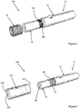
- FIGS 1 and 2 show perspective views of an aerosol-generating system 10 according to a first embodiment of the present invention.
- the aerosol-generating system 10 comprises an aerosol-generating device 12 comprising a power supply section 14 and a vaporiser section 16.
- the power supply section 14 comprises a button 15 for activating the aerosol-generating device 12.
- the power supply section 14 comprises a first end 20 defining a first end 21 of the aerosol-generating system and a second end 22.
- the vaporiser section 16 comprises a first end 24 configured for removable attachment to the second end 22 of the power supply section 14, and a second end 26 defining a second end 27 of the aerosol-generating system 10.
- a diameter of the second end 22 of the power supply section 14 is larger than a diameter of the first end 24 of the vaporiser section 16 so that a portion of the second end 22 of the power supply section 14 forms a flange 28.
- the aerosol-generating system 10 further comprises a cartridge 18 configured to be received on an outer surface 30 of the aerosol-generating device 12.
- the cartridge 18 has an annular shape and forms a sleeve configured to slide over an outer surface 32 of the vaporiser section 16 until an end of the cartridge 18 abuts the flange 28, as shown in Figure 2 .
- Figure 3 shows a cross-sectional view of the aerosol-generating device 12.
- the power supply section 14 defines a device air inlet 46 for admitting air into the power supply section 14, a controller 48 and a power supply 50.
- the device air inlet 46 is positioned on the flange 28.
- the vaporiser section 16 comprises a vaporiser air inlet 52 for receiving air from the power supply section 14, an airflow passage 54 in fluid communication with the vaporiser air inlet 52 at its upstream end, and a device air outlet 56 in fluid communication with the downstream end of the airflow passage 54.
- the vaporiser section 16 further comprises a liquid storage section 57 comprising a liquid aerosol-forming substrate 58 sorbed into an annular porous carrier material 60 positioned outside of the airflow passage 54.
- a liquid transfer element 62 comprising a capillary wick has first and second ends positioned in contact with the porous carrier material 60 and a central portion positioned within the airflow passage 54. Liquid aerosol-forming substrate 58 is wicked by capillary action along the capillary wick from the porous carrier material 60 to the central portion of the capillary wick.
- the vaporiser section 16 also comprises a first electric heater 64 comprising a resistive heating coil wound around the central portion of the capillary wick.
- the controller 48 controls a supply of electrical energy from the power supply 50 to the first electric heater 64 to heat and vaporise liquid aerosol-forming substrate 58 from the central portion of the capillary wick.
- the cartridge 18 When the cartridge 18 is received on the aerosol-generating device 12, as shown in Figure 4 , the cartridge 18 abuts the flange 28 and overlies the device air inlet 46.
- the cartridge 18 comprises a cartridge aerosol-forming substrate 42 wrapped in a porous wrapper 44 so that, during use, air may flow through the cartridge 18 and into the device air inlet 46.
- air is drawn into the aerosol-generating system 10 through the cartridge 18 where volatile compounds from the cartridge aerosol-forming substrate 42 are entrained in the airflow.
- the airflow then flows through the device air inlet 46, through the vaporiser air inlet 52 and into the airflow passage 54 where vaporised liquid aerosol-forming substrate 58 is entrained in the airflow.
- the airflow then flows out of the aerosol-generating system 10 through the device air outlet 56 to deliver to the user the vaporised liquid aerosol-forming substrate 58 and the volatile compounds from the cartridge aerosol-forming substrate 42.
- FIG. 5 shows an aerosol-generating system 100 according to a second embodiment of the present invention.
- the aerosol-generating system 100 is substantially the same as the aerosol-generating system 10 shown in Figures 1 to 4 , and like reference numerals are used to designate like parts.
- the aerosol-generating system 100 differs only by the addition of a second electric heater 164 to the outer surface 32 of the vaporiser section 16 of the aerosol-generating device 12.
- the second electric heater 164 comprises a plurality of discrete flexible film heaters 165.
- the cartridge 18 overlies the second electric heater 164 and the controller controls a supply of electrical energy from the power supply to the second electric heater 164 to heat the cartridge 18. Heating the cartridge 18 advantageously facilitates the release of volatile compounds from the cartridge aerosol-forming substrate.
- FIG 6 shows an aerosol-generating system 200 according to a third embodiment of the present invention.
- the aerosol-generating system 200 is substantially the same as the aerosol-generating systems 10 and 100 shown in Figures 1 to 5 , and like reference numerals are used to designate like parts.
- the aerosol-generating system 200 differs only by the addition of a removable cover 201.
- the removable cover 201 is configured to slide over the vaporiser section 16 and the cartridge 18 to cover the cartridge 18 during use of the aerosol-generating system 200.
- An upstream end 203 of the removable cover 201 abuts the flange 28 when the removable cover 201 is received on the aerosol-generating device 12.
- a downstream end 205 of the removable cover 201 is closed and comprises a cover air outlet 207 configured to overlie the device air outlet 56.
- the removable cover 201 is retained on the aerosol-generating device 12 by an interference fit.
- FIGS 7 to 9 show an aerosol-generating system 300 according to a fourth embodiment of the present invention.
- the aerosol-generating system 300 is similar to the aerosol-generating system 10 shown in Figures 1 to 4 , and like reference numerals are used to designate like parts.
- the aerosol-generating system 300 comprises an aerosol-generating device 312 having a power supply section 314 and a vaporiser section 316 configured for removable attachment to each other by a screw connection.
- the power supply section 314 comprises a male screw connector 315 configured to attach to a female screw connector on the vaporiser section 316.
- the aerosol-generating system 300 is configured so that, when the male screw connector 315 is fully inserted into the female screw connector, the second end 22 of the power supply section 314 is spaced apart from the first end 24 of the vaporiser section 316 to define the device air inlet 46 therebetween.
- the aerosol-generating system 300 comprises a cartridge 318 in the form of an annular ring.
- the cartridge 318 is configured to be received on the male screw connector 315 and sandwiched between the second end 22 of the power supply section 314 and the first end 24 of the vaporiser section 316 so that the cartridge 318 overlies the device air inlet 46.
- the vaporiser section 316 further comprises a mouthpiece 311 at the second end of the vaporiser section, the mouthpiece 311 comprising a mouthpiece air outlet 313 in fluid communication with the device air outlet.
- the operation of the aerosol-generating system 300 is substantially the same as the operation of the aerosol-generating system 10 shown in Figures 1 to 4 .
- air is drawn into the aerosol-generating system 300 through the cartridge 318 where volatile compounds from the cartridge aerosol-forming substrate 342 are entrained in the airflow.
- the airflow then flows through the device air inlet 46, through the vaporiser air inlet 52 and into the airflow passage 54 where vaporised liquid aerosol-forming substrate 58 is entrained in the airflow.
- the airflow then flows out of the aerosol-generating system 300 through the device air outlet 56 and the mouthpiece air outlet 313 to deliver to the user the vaporised liquid aerosol-forming substrate 58 and the volatile compounds from the cartridge aerosol-forming substrate 342.
- FIG 10 shows a cartridge 418 according to a fifth embodiment of the present invention.
- the cartridge 418 is substantially the same as the cartridge 318 shown in Figures 7 to 9 , except the cartridge 418 has a split-ring shape, which may facilitate engagement and disengagement of the cartridge 418 with an aerosol-generating device.
- the cartridge 418 can be used with the aerosol-generating device 312 shown in Figures 7 to 9 .
- FIG 11 shows a cartridge 518 according to a sixth embodiment of the present invention.
- the cartridge 518 is substantially the same as the cartridge 318 shown in Figures 7 to 9 , except the cartridge 518 has a C-shape, which may facilitate engagement and disengagement of the cartridge 518 with an aerosol-generating device.
- the cartridge 518 can be used with the aerosol-generating device 312 shown in Figures 7 to 9 .
Landscapes
- Health & Medical Sciences (AREA)
- Engineering & Computer Science (AREA)
- Chemical & Material Sciences (AREA)
- Chemical Kinetics & Catalysis (AREA)
- General Chemical & Material Sciences (AREA)
- Hematology (AREA)
- Public Health (AREA)
- Anesthesiology (AREA)
- Biomedical Technology (AREA)
- Heart & Thoracic Surgery (AREA)
- Bioinformatics & Cheminformatics (AREA)
- Life Sciences & Earth Sciences (AREA)
- Animal Behavior & Ethology (AREA)
- General Health & Medical Sciences (AREA)
- Pulmonology (AREA)
- Veterinary Medicine (AREA)
- Disinfection, Sterilisation Or Deodorisation Of Air (AREA)
- Fuel Cell (AREA)
- Catching Or Destruction (AREA)
- Nozzles (AREA)
- Packaging Of Annular Or Rod-Shaped Articles, Wearing Apparel, Cassettes, Or The Like (AREA)
- Containers And Packaging Bodies Having A Special Means To Remove Contents (AREA)
- Filling Or Discharging Of Gas Storage Vessels (AREA)
Claims (13)
- Aerosolerzeugungssystem (10), aufweisend:eine Patrone (18), die ein patroniertes aerosolbildendes Substrat (42) aufweist, wobei die Patrone (18) eine ringförmige Form aufweist; undeine Aerosolerzeugungsvorrichtung (12) mit einem ersten Ende (21), einem zweiten Ende (27) und einer Länge, die sich zwischen dem ersten Ende (21) und dem zweiten Ende (27) erstreckt, wobei die Aerosolerzeugungsvorrichtung (12) aufweist:einen Flüssigspeicherabschnitt (57), der ein flüssiges aerosolbildendes Substrat (58) aufweist, das innerhalb des Flüssigspeicherabschnitts (57) positioniert ist;eine erste elektrische Heizvorrichtung (64), die zum Erwärmen eines flüssigen aerosolbildenden Substrats (58) aus dem Flüssigspeicherabschnitt (57) während des Gebrauchs des Aerosolerzeugungssystems (10) ausgelegt ist;einen Stromversorgungsabschnitt (14), der eine Stromversorgung (50) und eine Steuerung (48) zum Regeln einer Versorgung von elektrischem Strom von der Stromversorgung (50) zu der ersten elektrischen Heizvorrichtung (64) aufweist;einen Gerätelufteinlass (46), der zwischen dem ersten Ende (21) und dem zweiten Ende (27) der Aerosolerzeugungsvorrichtung (12) positioniert ist undeinen Geräteluftauslass (56), der an dem zweiten Ende (27) der Aerosolerzeugungsvorrichtung (12) positioniert ist;wobei der Stromversorgungsabschnitt (14) ein erstes Ende (20), das das erste Ende (21) der Aerosolerzeugungsvorrichtung (12) ausbildet, und ein zweites Ende (22) hat, wobei der Flüssigspeicherabschnitt (57) ein erstes Ende (24), das zur abnehmbaren Befestigung an dem zweiten Ende (22) des Stromversorgungsabschnitts (14) ausgelegt ist, und ein zweites Ende (26), das das zweite Ende (27) der Aerosolerzeugungsvorrichtung (12) ausbildet, hat;wobei eine Außenfläche (32) der Aerosolerzeugungsvorrichtung (12) einen Flansch (28) ausbildet, wobei eines des ersten Endes (24) des Flüssigspeicherabschnitts (57) und des zweiten Endes (22) des Stromversorgungsabschnitts (14) den Flansch (28) ausbildet, wenn der Flüssigspeicherabschnitt (57) an dem Stromversorgungsabschnitt (14) befestigt ist undwobei die Aerosolerzeugungsvorrichtung (12) so ausgelegt ist, dass sie die Patrone (18) an der Aerosolerzeugungsvorrichtung (12) aufnimmt, sodass die Patrone (18) durch den Flansch (28) aufgenommen wird, wenn die Patrone (18) an der Aerosolerzeugungsvorrichtung (12) aufgenommen wird, und wobei der Gerätelufteinlass (46) nahe des Flansches (28) positioniert ist, sodass die Patrone (18) zumindest teilweise über dem Gerätelufteinlass (46) liegt, wenn die Patrone (18) durch den Flansch (28) aufgenommen wird.
- Aerosolerzeugungssystem (10) nach Anspruch 1, wobei der Gerätelufteinlass (46) auf dem Flansch (28) positioniert ist, sodass ein Ende der Patrone (18) an dem Gerätelufteinlass (46) anliegt, wenn die Patrone (18) durch den Flansch (28) aufgenommen wird.
- Aerosolerzeugungssystem (10) nach Anspruch 1, wobei der Gerätelufteinlass (46) an der Außenfläche (32) der Aerosolerzeugungsvorrichtung (12) neben dem Flansch (28) positioniert ist, sodass eine Innenfläche der Patrone (18) zumindest teilweise über dem Gerätelufteinlass (46) liegt, wenn die Patrone (18) durch den Flansch (28) aufgenommen wird.
- Aerosolerzeugungssystem (100) nach einem der vorhergehenden Ansprüche, das ferner eine zweite elektrische Heizvorrichtung (164) aufweist, die an einer Außenfläche (32) der Aerosolerzeugungsvorrichtung (12) vorgesehen ist, wobei die zweite elektrische Heizvorrichtung (164) so positioniert ist, dass die Patrone (18) zumindest teilweise über der zweiten elektrischen Heizvorrichtung (164) liegt, wenn die Patrone (18) auf der Aerosolerzeugungsvorrichtung (12) aufgenommen wird, und wobei die Steuerung (48) so ausgelegt ist, dass sie eine Versorgung von elektrischem Strom von der Stromversorgung (50) zu der zweiten elektrischen Heizvorrichtung (164) regelt, wenn die Patrone (18) auf der Aerosolerzeugungsvorrichtung (12) aufgenommen wird.
- Aerosolerzeugungssystem (200) nach einem der vorhergehenden Ansprüche, das ferner eine abnehmbare Abdeckung (201) aufweist, die so ausgelegt ist, dass sie zumindest einen Teil der Aerosolerzeugungsvorrichtung (12) aufnimmt, wobei die abnehmbare Abdeckung (201) so ausgelegt ist, dass sie über der Patrone (18) liegt, wenn die Patrone (18) auf der Aerosolerzeugungsvorrichtung (12) aufgenommen wird und wenn die abnehmbare Abdeckung (201) mit der Aerosolerzeugungsvorrichtung (12) in Eingriff steht.
- Aerosolerzeugungssystem (200) nach Anspruch 5, wobei die abnehmbare Abdeckung (201) einen Abdeckluftauslass (207) aufweist, der für eine Fluidverbindung mit dem Geräteluftauslass (56) ausgelegt ist, wenn die abnehmbare Abdeckung (201) mit der Aerosolerzeugungsvorrichtung (12) in Eingriff steht.
- Aerosolerzeugungssystem (200) nach Anspruch 5 oder 6, wobei die abnehmbare Abdeckung (201) ferner einen Abdecklufteinlass aufweist, der für eine Fluidverbindung mit der Patrone (18) ausgelegt ist, wenn die Patrone (18) auf der Aerosolerzeugungsvorrichtung (12) aufgenommen wird und wenn die abnehmbare Abdeckung (201) mit der Aerosolerzeugungsvorrichtung (12) in Eingriff steht.
- Aerosolerzeugungssystem (200) nach Anspruch 5, 6 oder 7, wobei ein erstes Ende (203) der abnehmbaren Abdeckung (201) so ausgelegt ist, dass es an dem Flansch (28) anliegt, wenn die abnehmbare Abdeckung (201) mit der Aerosolerzeugungsvorrichtung (12) in Eingriff steht.
- Aerosolerzeugungssystem (10) nach einem der vorhergehenden Ansprüche, wobei die Patrone (18) eine Hülse ausbildet, die so ausgelegt ist, dass sie auf einen Teil der Aerosolerzeugungsvorrichtung (12) gleitet.
- Aerosolerzeugungssystem (300) nach einem der Ansprüche 1 bis 8, wobei der Flüssigspeicherabschnitt (57) zur abnehmbaren Befestigung an dem Stromversorgungsabschnitt (314) ausgelegt ist und wobei die Patrone (318) so ausgelegt ist, dass sie zwischen dem Flüssigspeicherabschnitt (57) und dem Stromversorgungsabschnitt (314) aufgenommen wird.
- Aerosolerzeugungssystem (300) nach Anspruch 10, wobei die Patrone (318) eine ringförmige Scheibe ausbildet.
- Aerosolerzeugungssystem (300) nach Anspruch 11, wobei die ringförmige Scheibe eine aus einer Ringform, einer zweigeteilten Form oder einer C-Form ist.
- Aerosolerzeugungssystem (10) nach einem der vorhergehenden Ansprüche, wobei die Patrone (18) eine poröse Umhüllung (44) aufweist, die zumindest über einem Teil des patronisierten aerosolbildenden Substrats (42) liegt.
Applications Claiming Priority (2)
| Application Number | Priority Date | Filing Date | Title |
|---|---|---|---|
| EP16205104 | 2016-12-19 | ||
| PCT/EP2017/081931 WO2018114380A1 (en) | 2016-12-19 | 2017-12-07 | Aerosol-generating system having an external cartridge |
Publications (2)
| Publication Number | Publication Date |
|---|---|
| EP3554293A1 EP3554293A1 (de) | 2019-10-23 |
| EP3554293B1 true EP3554293B1 (de) | 2021-02-03 |
Family
ID=57570718
Family Applications (1)
| Application Number | Title | Priority Date | Filing Date |
|---|---|---|---|
| EP17816652.6A Active EP3554293B1 (de) | 2016-12-19 | 2017-12-07 | Aerosolerzeugungssystem mit externer kartusche |
Country Status (7)
| Country | Link |
|---|---|
| US (4) | US10743584B2 (de) |
| EP (1) | EP3554293B1 (de) |
| JP (1) | JP7121746B2 (de) |
| KR (1) | KR102579501B1 (de) |
| CN (1) | CN110022703B (de) |
| RU (1) | RU2747613C2 (de) |
| WO (1) | WO2018114380A1 (de) |
Cited By (1)
| Publication number | Priority date | Publication date | Assignee | Title |
|---|---|---|---|---|
| US11730199B2 (en) | 2018-06-07 | 2023-08-22 | Juul Labs, Inc. | Cartridges for vaporizer devices |
Families Citing this family (11)
| Publication number | Priority date | Publication date | Assignee | Title |
|---|---|---|---|---|
| US10674765B2 (en) * | 2017-03-29 | 2020-06-09 | Rai Strategic Holdings, Inc. | Aerosol delivery device with improved atomizer |
| GB201818270D0 (en) | 2018-11-09 | 2018-12-26 | Nicoventures Trading Ltd | Component for a vapour provision system |
| KR102332541B1 (ko) * | 2018-11-23 | 2021-11-29 | 주식회사 케이티앤지 | 에어로졸 생성 물품 |
| JP7528081B2 (ja) * | 2018-12-06 | 2024-08-05 | フィリップ・モーリス・プロダクツ・ソシエテ・アノニム | 狭い中空管状フィルターを有するエアロゾル発生物品 |
| EP3692833A1 (de) * | 2019-02-07 | 2020-08-12 | Nerudia Ltd. | Rauchersatzvorrichtung |
| EA202193291A1 (ru) * | 2019-06-21 | 2022-03-29 | ДжейТи ИНТЕРНЕШНЛ СА | Нагреваемая, но не сжигаемая палочка, содержащая пенообразный материал, генерирующий аэрозоль, расположенный в емкости |
| EP3794970A1 (de) * | 2019-09-20 | 2021-03-24 | Nerudia Limited | Rauchersatzvorrichtung |
| GB202012723D0 (en) * | 2020-08-14 | 2020-09-30 | Nicoventures Holdings Ltd | Aerosol generation |
| CN116801749A (zh) * | 2021-02-18 | 2023-09-22 | 菲利普莫里斯生产公司 | 用于气溶胶生成装置的具有可滑动密封元件的可替换的筒 |
| KR102713760B1 (ko) * | 2021-07-21 | 2024-10-07 | 주식회사 케이티앤지 | 에어로졸 생성장치 및 에어로졸 생성장치 제조방법 |
| CN120417792A (zh) * | 2022-12-30 | 2025-08-01 | 菲利普莫里斯生产公司 | 具有可移除风味元件的气溶胶生成系统 |
Family Cites Families (31)
| Publication number | Priority date | Publication date | Assignee | Title |
|---|---|---|---|---|
| US5692525A (en) | 1992-09-11 | 1997-12-02 | Philip Morris Incorporated | Cigarette for electrical smoking system |
| CN201067079Y (zh) * | 2006-05-16 | 2008-06-04 | 韩力 | 仿真气溶胶吸入器 |
| TW201023769A (en) | 2008-10-23 | 2010-07-01 | Japan Tobacco Inc | Non-burning type flavor inhalation article |
| EP2316286A1 (de) | 2009-10-29 | 2011-05-04 | Philip Morris Products S.A. | Elektrisch erhitztes Rauchsystem mit verbesserter Heizvorrichtung |
| EP2672847B1 (de) | 2011-02-11 | 2015-04-22 | Batmark Limited | Inhalatorkomponente |
| WO2013007020A1 (zh) | 2011-07-12 | 2013-01-17 | Liu Qiuming | 一种电子烤烟 |
| US9078473B2 (en) | 2011-08-09 | 2015-07-14 | R.J. Reynolds Tobacco Company | Smoking articles and use thereof for yielding inhalation materials |
| WO2013034453A1 (en) | 2011-09-06 | 2013-03-14 | British American Tobacco (Investments) Limited | Heating smokeable material |
| CA3079706C (en) * | 2011-11-21 | 2023-08-01 | Philip Morris Products S.A. | Ejector for an aerosol-generating device |
| UA113744C2 (xx) * | 2011-12-08 | 2017-03-10 | Пристрій для утворення аерозолю з внутрішнім нагрівачем | |
| UA112883C2 (uk) * | 2011-12-08 | 2016-11-10 | Філіп Морріс Продактс С.А. | Пристрій для утворення аерозолю з капілярним примежовим шаром |
| RU2602053C2 (ru) * | 2012-01-03 | 2016-11-10 | Филип Моррис Продактс С.А. | Генерирующее аэрозоль устройство и система с усовершенствованным потоком воздуха |
| US9289014B2 (en) * | 2012-02-22 | 2016-03-22 | Altria Client Services Llc | Electronic smoking article and improved heater element |
| WO2014047954A1 (zh) | 2012-09-29 | 2014-04-03 | Liu Shuigen | 一种电子吸烟装置 |
| WO2014047955A1 (zh) | 2012-09-29 | 2014-04-03 | Wu Changming | 一种电子吸烟装置 |
| KR102169734B1 (ko) * | 2012-11-28 | 2020-10-26 | 이-니코틴 테크놀로지, 인크. | 화합물 전달을 위한 방법 및 장치 |
| US20140150785A1 (en) * | 2012-12-05 | 2014-06-05 | Vire, L.L.C. | Electronic cigarette or inhaler |
| MX2015007973A (es) * | 2012-12-17 | 2017-08-24 | Sis Resources Ltd | Mejora de sabor para cigarro electronico. |
| US20150351456A1 (en) * | 2013-01-08 | 2015-12-10 | L. Perrigo Company | Electronic cigarette |
| AU2013382371B2 (en) | 2013-03-15 | 2018-09-27 | Philip Morris Products S.A. | An aerosol-generating system with a replacable mouthpiece cover |
| CN105592734A (zh) | 2013-07-24 | 2016-05-18 | 奥驰亚客户服务有限责任公司 | 具有替代的气流路径的电子吸烟器具 |
| WO2015073975A1 (en) * | 2013-11-15 | 2015-05-21 | VMR Products, LLC | Vaporizer with cover sleeve |
| UA121461C2 (uk) * | 2014-02-10 | 2020-06-10 | Філіп Морріс Продактс С.А. | Система, що генерує аерозоль, що містить пристрій і картридж, у якій пристрій забезпечує електричний контакт із картриджем |
| DE202014001718U1 (de) | 2014-02-27 | 2015-05-28 | Xeo Holding GmbH | Rauchvorrichtung |
| EP2929903B1 (de) * | 2014-04-08 | 2018-05-09 | Shenzhen First Union Technology Co., Ltd. | Zerstäuber und elektronische zigarette |
| US20150335070A1 (en) | 2014-05-20 | 2015-11-26 | R.J. Reynolds Tobacco Company | Electrically-powered aerosol delivery system |
| WO2015180167A1 (zh) * | 2014-05-30 | 2015-12-03 | 深圳麦克韦尔股份有限公司 | 电子烟及其雾化器 |
| US20170208866A1 (en) * | 2014-07-31 | 2017-07-27 | Huizhou Kimree Technology Co., Ltd. | Electronic cigarette |
| US10219541B2 (en) * | 2014-10-29 | 2019-03-05 | Lubby Holdings, LLC | Cartridge cover for personal vaporizer |
| CN107106797A (zh) | 2014-10-29 | 2017-08-29 | 奥驰亚客户服务有限责任公司 | 电子烟筒体 |
| GB201503411D0 (en) | 2015-02-27 | 2015-04-15 | British American Tobacco Co | Apparatus and method for generating an inhalable medium, and a cartridge for use therewith |
-
2017
- 2017-12-07 CN CN201780072717.9A patent/CN110022703B/zh active Active
- 2017-12-07 RU RU2019119018A patent/RU2747613C2/ru active
- 2017-12-07 KR KR1020197014401A patent/KR102579501B1/ko active Active
- 2017-12-07 EP EP17816652.6A patent/EP3554293B1/de active Active
- 2017-12-07 WO PCT/EP2017/081931 patent/WO2018114380A1/en not_active Ceased
- 2017-12-07 JP JP2019553633A patent/JP7121746B2/ja active Active
- 2017-12-19 US US15/846,694 patent/US10743584B2/en active Active
-
2020
- 2020-06-29 US US16/915,146 patent/US11425795B2/en active Active
-
2022
- 2022-07-20 US US17/868,910 patent/US12439963B2/en active Active
-
2025
- 2025-10-03 US US19/349,201 patent/US20260026547A1/en active Pending
Non-Patent Citations (1)
| Title |
|---|
| None * |
Cited By (2)
| Publication number | Priority date | Publication date | Assignee | Title |
|---|---|---|---|---|
| US11730199B2 (en) | 2018-06-07 | 2023-08-22 | Juul Labs, Inc. | Cartridges for vaporizer devices |
| US12543791B2 (en) | 2018-06-07 | 2026-02-10 | Juul Labs, Inc. | Cartridges for vaporizer devices |
Also Published As
| Publication number | Publication date |
|---|---|
| EP3554293A1 (de) | 2019-10-23 |
| US11425795B2 (en) | 2022-08-23 |
| US10743584B2 (en) | 2020-08-18 |
| RU2747613C2 (ru) | 2021-05-11 |
| KR102579501B1 (ko) | 2023-09-19 |
| JP7121746B2 (ja) | 2022-08-18 |
| RU2019119018A3 (de) | 2021-03-15 |
| CN110022703B (zh) | 2022-05-17 |
| WO2018114380A1 (en) | 2018-06-28 |
| JP2020501608A (ja) | 2020-01-23 |
| US20180168232A1 (en) | 2018-06-21 |
| US20200329764A1 (en) | 2020-10-22 |
| US20260026547A1 (en) | 2026-01-29 |
| US12439963B2 (en) | 2025-10-14 |
| CN110022703A (zh) | 2019-07-16 |
| US20220346443A1 (en) | 2022-11-03 |
| KR20190089870A (ko) | 2019-07-31 |
| RU2019119018A (ru) | 2021-01-19 |
Similar Documents
| Publication | Publication Date | Title |
|---|---|---|
| US12514297B2 (en) | Aerosol-generating system having a cartridge and a bypass air inlet | |
| US11590302B2 (en) | Aerosol-generating system having a cartridge and a bypass air inlet | |
| EP3554293B1 (de) | Aerosolerzeugungssystem mit externer kartusche | |
| EP3554294B1 (de) | Aerosolerzeugungssystem mit mehreren aerosolerzeugenden substraten und einem durchstosselement | |
| US12382991B2 (en) | Aerosol-generating system comprising a modular assembly | |
| EP3554289B1 (de) | Aerosolerzeugungssystem mit einer kartusche mit einer seitlichen öffnung | |
| US11400240B2 (en) | Aerosol-generating system comprising a modular assembly | |
| EP3537901B1 (de) | Aerosolerzeugungssystem bestehend aus festen und flüssigen aerosolerzeugungssubstraten |
Legal Events
| Date | Code | Title | Description |
|---|---|---|---|
| STAA | Information on the status of an ep patent application or granted ep patent |
Free format text: STATUS: UNKNOWN |
|
| STAA | Information on the status of an ep patent application or granted ep patent |
Free format text: STATUS: THE INTERNATIONAL PUBLICATION HAS BEEN MADE |
|
| PUAI | Public reference made under article 153(3) epc to a published international application that has entered the european phase |
Free format text: ORIGINAL CODE: 0009012 |
|
| STAA | Information on the status of an ep patent application or granted ep patent |
Free format text: STATUS: REQUEST FOR EXAMINATION WAS MADE |
|
| 17P | Request for examination filed |
Effective date: 20190524 |
|
| AK | Designated contracting states |
Kind code of ref document: A1 Designated state(s): AL AT BE BG CH CY CZ DE DK EE ES FI FR GB GR HR HU IE IS IT LI LT LU LV MC MK MT NL NO PL PT RO RS SE SI SK SM TR |
|
| AX | Request for extension of the european patent |
Extension state: BA ME |
|
| DAV | Request for validation of the european patent (deleted) | ||
| DAX | Request for extension of the european patent (deleted) | ||
| REG | Reference to a national code |
Ref country code: DE Ref legal event code: R079 Ref document number: 602017032365 Country of ref document: DE Free format text: PREVIOUS MAIN CLASS: A24F0047000000 Ipc: A24F0040100000 |
|
| GRAP | Despatch of communication of intention to grant a patent |
Free format text: ORIGINAL CODE: EPIDOSNIGR1 |
|
| STAA | Information on the status of an ep patent application or granted ep patent |
Free format text: STATUS: GRANT OF PATENT IS INTENDED |
|
| RIC1 | Information provided on ipc code assigned before grant |
Ipc: A24F 40/30 20200101ALI20200622BHEP Ipc: A24F 40/42 20200101ALI20200622BHEP Ipc: A24F 40/10 20200101AFI20200622BHEP |
|
| INTG | Intention to grant announced |
Effective date: 20200717 |
|
| GRAS | Grant fee paid |
Free format text: ORIGINAL CODE: EPIDOSNIGR3 |
|
| GRAA | (expected) grant |
Free format text: ORIGINAL CODE: 0009210 |
|
| STAA | Information on the status of an ep patent application or granted ep patent |
Free format text: STATUS: THE PATENT HAS BEEN GRANTED |
|
| AK | Designated contracting states |
Kind code of ref document: B1 Designated state(s): AL AT BE BG CH CY CZ DE DK EE ES FI FR GB GR HR HU IE IS IT LI LT LU LV MC MK MT NL NO PL PT RO RS SE SI SK SM TR |
|
| REG | Reference to a national code |
Ref country code: GB Ref legal event code: FG4D |
|
| REG | Reference to a national code |
Ref country code: AT Ref legal event code: REF Ref document number: 1359515 Country of ref document: AT Kind code of ref document: T Effective date: 20210215 Ref country code: CH Ref legal event code: EP |
|
| REG | Reference to a national code |
Ref country code: DE Ref legal event code: R096 Ref document number: 602017032365 Country of ref document: DE |
|
| REG | Reference to a national code |
Ref country code: IE Ref legal event code: FG4D |
|
| REG | Reference to a national code |
Ref country code: NL Ref legal event code: FP |
|
| REG | Reference to a national code |
Ref country code: LT Ref legal event code: MG9D |
|
| REG | Reference to a national code |
Ref country code: AT Ref legal event code: MK05 Ref document number: 1359515 Country of ref document: AT Kind code of ref document: T Effective date: 20210203 |
|
| PG25 | Lapsed in a contracting state [announced via postgrant information from national office to epo] |
Ref country code: LT Free format text: LAPSE BECAUSE OF FAILURE TO SUBMIT A TRANSLATION OF THE DESCRIPTION OR TO PAY THE FEE WITHIN THE PRESCRIBED TIME-LIMIT Effective date: 20210203 Ref country code: BG Free format text: LAPSE BECAUSE OF FAILURE TO SUBMIT A TRANSLATION OF THE DESCRIPTION OR TO PAY THE FEE WITHIN THE PRESCRIBED TIME-LIMIT Effective date: 20210503 Ref country code: PT Free format text: LAPSE BECAUSE OF FAILURE TO SUBMIT A TRANSLATION OF THE DESCRIPTION OR TO PAY THE FEE WITHIN THE PRESCRIBED TIME-LIMIT Effective date: 20210604 Ref country code: NO Free format text: LAPSE BECAUSE OF FAILURE TO SUBMIT A TRANSLATION OF THE DESCRIPTION OR TO PAY THE FEE WITHIN THE PRESCRIBED TIME-LIMIT Effective date: 20210503 Ref country code: GR Free format text: LAPSE BECAUSE OF FAILURE TO SUBMIT A TRANSLATION OF THE DESCRIPTION OR TO PAY THE FEE WITHIN THE PRESCRIBED TIME-LIMIT Effective date: 20210504 Ref country code: HR Free format text: LAPSE BECAUSE OF FAILURE TO SUBMIT A TRANSLATION OF THE DESCRIPTION OR TO PAY THE FEE WITHIN THE PRESCRIBED TIME-LIMIT Effective date: 20210203 Ref country code: FI Free format text: LAPSE BECAUSE OF FAILURE TO SUBMIT A TRANSLATION OF THE DESCRIPTION OR TO PAY THE FEE WITHIN THE PRESCRIBED TIME-LIMIT Effective date: 20210203 |
|
| PG25 | Lapsed in a contracting state [announced via postgrant information from national office to epo] |
Ref country code: SE Free format text: LAPSE BECAUSE OF FAILURE TO SUBMIT A TRANSLATION OF THE DESCRIPTION OR TO PAY THE FEE WITHIN THE PRESCRIBED TIME-LIMIT Effective date: 20210203 Ref country code: LV Free format text: LAPSE BECAUSE OF FAILURE TO SUBMIT A TRANSLATION OF THE DESCRIPTION OR TO PAY THE FEE WITHIN THE PRESCRIBED TIME-LIMIT Effective date: 20210203 Ref country code: RS Free format text: LAPSE BECAUSE OF FAILURE TO SUBMIT A TRANSLATION OF THE DESCRIPTION OR TO PAY THE FEE WITHIN THE PRESCRIBED TIME-LIMIT Effective date: 20210203 Ref country code: PL Free format text: LAPSE BECAUSE OF FAILURE TO SUBMIT A TRANSLATION OF THE DESCRIPTION OR TO PAY THE FEE WITHIN THE PRESCRIBED TIME-LIMIT Effective date: 20210203 Ref country code: AT Free format text: LAPSE BECAUSE OF FAILURE TO SUBMIT A TRANSLATION OF THE DESCRIPTION OR TO PAY THE FEE WITHIN THE PRESCRIBED TIME-LIMIT Effective date: 20210203 |
|
| PG25 | Lapsed in a contracting state [announced via postgrant information from national office to epo] |
Ref country code: IS Free format text: LAPSE BECAUSE OF FAILURE TO SUBMIT A TRANSLATION OF THE DESCRIPTION OR TO PAY THE FEE WITHIN THE PRESCRIBED TIME-LIMIT Effective date: 20210603 |
|
| PG25 | Lapsed in a contracting state [announced via postgrant information from national office to epo] |
Ref country code: SM Free format text: LAPSE BECAUSE OF FAILURE TO SUBMIT A TRANSLATION OF THE DESCRIPTION OR TO PAY THE FEE WITHIN THE PRESCRIBED TIME-LIMIT Effective date: 20210203 Ref country code: CZ Free format text: LAPSE BECAUSE OF FAILURE TO SUBMIT A TRANSLATION OF THE DESCRIPTION OR TO PAY THE FEE WITHIN THE PRESCRIBED TIME-LIMIT Effective date: 20210203 Ref country code: EE Free format text: LAPSE BECAUSE OF FAILURE TO SUBMIT A TRANSLATION OF THE DESCRIPTION OR TO PAY THE FEE WITHIN THE PRESCRIBED TIME-LIMIT Effective date: 20210203 |
|
| REG | Reference to a national code |
Ref country code: DE Ref legal event code: R097 Ref document number: 602017032365 Country of ref document: DE |
|
| PG25 | Lapsed in a contracting state [announced via postgrant information from national office to epo] |
Ref country code: DK Free format text: LAPSE BECAUSE OF FAILURE TO SUBMIT A TRANSLATION OF THE DESCRIPTION OR TO PAY THE FEE WITHIN THE PRESCRIBED TIME-LIMIT Effective date: 20210203 Ref country code: SK Free format text: LAPSE BECAUSE OF FAILURE TO SUBMIT A TRANSLATION OF THE DESCRIPTION OR TO PAY THE FEE WITHIN THE PRESCRIBED TIME-LIMIT Effective date: 20210203 Ref country code: RO Free format text: LAPSE BECAUSE OF FAILURE TO SUBMIT A TRANSLATION OF THE DESCRIPTION OR TO PAY THE FEE WITHIN THE PRESCRIBED TIME-LIMIT Effective date: 20210203 |
|
| PLBE | No opposition filed within time limit |
Free format text: ORIGINAL CODE: 0009261 |
|
| STAA | Information on the status of an ep patent application or granted ep patent |
Free format text: STATUS: NO OPPOSITION FILED WITHIN TIME LIMIT |
|
| 26N | No opposition filed |
Effective date: 20211104 |
|
| PG25 | Lapsed in a contracting state [announced via postgrant information from national office to epo] |
Ref country code: ES Free format text: LAPSE BECAUSE OF FAILURE TO SUBMIT A TRANSLATION OF THE DESCRIPTION OR TO PAY THE FEE WITHIN THE PRESCRIBED TIME-LIMIT Effective date: 20210203 Ref country code: AL Free format text: LAPSE BECAUSE OF FAILURE TO SUBMIT A TRANSLATION OF THE DESCRIPTION OR TO PAY THE FEE WITHIN THE PRESCRIBED TIME-LIMIT Effective date: 20210203 |
|
| PG25 | Lapsed in a contracting state [announced via postgrant information from national office to epo] |
Ref country code: SI Free format text: LAPSE BECAUSE OF FAILURE TO SUBMIT A TRANSLATION OF THE DESCRIPTION OR TO PAY THE FEE WITHIN THE PRESCRIBED TIME-LIMIT Effective date: 20210203 |
|
| PG25 | Lapsed in a contracting state [announced via postgrant information from national office to epo] |
Ref country code: IS Free format text: LAPSE BECAUSE OF FAILURE TO SUBMIT A TRANSLATION OF THE DESCRIPTION OR TO PAY THE FEE WITHIN THE PRESCRIBED TIME-LIMIT Effective date: 20210603 |
|
| PG25 | Lapsed in a contracting state [announced via postgrant information from national office to epo] |
Ref country code: MC Free format text: LAPSE BECAUSE OF FAILURE TO SUBMIT A TRANSLATION OF THE DESCRIPTION OR TO PAY THE FEE WITHIN THE PRESCRIBED TIME-LIMIT Effective date: 20210203 |
|
| REG | Reference to a national code |
Ref country code: BE Ref legal event code: MM Effective date: 20211231 |
|
| PG25 | Lapsed in a contracting state [announced via postgrant information from national office to epo] |
Ref country code: LU Free format text: LAPSE BECAUSE OF NON-PAYMENT OF DUE FEES Effective date: 20211207 Ref country code: IE Free format text: LAPSE BECAUSE OF NON-PAYMENT OF DUE FEES Effective date: 20211207 |
|
| PG25 | Lapsed in a contracting state [announced via postgrant information from national office to epo] |
Ref country code: BE Free format text: LAPSE BECAUSE OF NON-PAYMENT OF DUE FEES Effective date: 20211231 |
|
| PG25 | Lapsed in a contracting state [announced via postgrant information from national office to epo] |
Ref country code: CY Free format text: LAPSE BECAUSE OF FAILURE TO SUBMIT A TRANSLATION OF THE DESCRIPTION OR TO PAY THE FEE WITHIN THE PRESCRIBED TIME-LIMIT Effective date: 20210203 |
|
| P01 | Opt-out of the competence of the unified patent court (upc) registered |
Effective date: 20230529 |
|
| PG25 | Lapsed in a contracting state [announced via postgrant information from national office to epo] |
Ref country code: HU Free format text: LAPSE BECAUSE OF FAILURE TO SUBMIT A TRANSLATION OF THE DESCRIPTION OR TO PAY THE FEE WITHIN THE PRESCRIBED TIME-LIMIT; INVALID AB INITIO Effective date: 20171207 |
|
| PG25 | Lapsed in a contracting state [announced via postgrant information from national office to epo] |
Ref country code: MK Free format text: LAPSE BECAUSE OF FAILURE TO SUBMIT A TRANSLATION OF THE DESCRIPTION OR TO PAY THE FEE WITHIN THE PRESCRIBED TIME-LIMIT Effective date: 20210203 |
|
| PG25 | Lapsed in a contracting state [announced via postgrant information from national office to epo] |
Ref country code: MT Free format text: LAPSE BECAUSE OF FAILURE TO SUBMIT A TRANSLATION OF THE DESCRIPTION OR TO PAY THE FEE WITHIN THE PRESCRIBED TIME-LIMIT Effective date: 20210203 |
|
| PGFP | Annual fee paid to national office [announced via postgrant information from national office to epo] |
Ref country code: CH Payment date: 20250101 Year of fee payment: 8 |
|
| PG25 | Lapsed in a contracting state [announced via postgrant information from national office to epo] |
Ref country code: TR Free format text: LAPSE BECAUSE OF FAILURE TO SUBMIT A TRANSLATION OF THE DESCRIPTION OR TO PAY THE FEE WITHIN THE PRESCRIBED TIME-LIMIT Effective date: 20210203 |
|
| REG | Reference to a national code |
Ref country code: CH Ref legal event code: U11 Free format text: ST27 STATUS EVENT CODE: U-0-0-U10-U11 (AS PROVIDED BY THE NATIONAL OFFICE) Effective date: 20260101 |
|
| PGFP | Annual fee paid to national office [announced via postgrant information from national office to epo] |
Ref country code: DE Payment date: 20251211 Year of fee payment: 9 |
|
| PGFP | Annual fee paid to national office [announced via postgrant information from national office to epo] |
Ref country code: GB Payment date: 20251219 Year of fee payment: 9 |
|
| PGFP | Annual fee paid to national office [announced via postgrant information from national office to epo] |
Ref country code: IT Payment date: 20251222 Year of fee payment: 9 |
|
| PGFP | Annual fee paid to national office [announced via postgrant information from national office to epo] |
Ref country code: FR Payment date: 20251229 Year of fee payment: 9 Ref country code: NL Payment date: 20251219 Year of fee payment: 9 |