EP3554221B1 - System zur erkennung des flüssigkeitsflusses in einer flüssigkeitsübertragungsvorrichtung und bewässerungssystem mit einem flüssigkeitsflusserkennungssystem - Google Patents
System zur erkennung des flüssigkeitsflusses in einer flüssigkeitsübertragungsvorrichtung und bewässerungssystem mit einem flüssigkeitsflusserkennungssystem Download PDFInfo
- Publication number
- EP3554221B1 EP3554221B1 EP17881896.9A EP17881896A EP3554221B1 EP 3554221 B1 EP3554221 B1 EP 3554221B1 EP 17881896 A EP17881896 A EP 17881896A EP 3554221 B1 EP3554221 B1 EP 3554221B1
- Authority
- EP
- European Patent Office
- Prior art keywords
- hose
- sensor
- pipe
- fluid flow
- sprinkler
- Prior art date
- Legal status (The legal status is an assumption and is not a legal conclusion. Google has not performed a legal analysis and makes no representation as to the accuracy of the status listed.)
- Active
Links
Images
Classifications
-
- B—PERFORMING OPERATIONS; TRANSPORTING
- B05—SPRAYING OR ATOMISING IN GENERAL; APPLYING FLUENT MATERIALS TO SURFACES, IN GENERAL
- B05B—SPRAYING APPARATUS; ATOMISING APPARATUS; NOZZLES
- B05B12/00—Arrangements for controlling delivery; Arrangements for controlling the spray area
- B05B12/004—Arrangements for controlling delivery; Arrangements for controlling the spray area comprising sensors for monitoring the delivery, e.g. by displaying the sensed value or generating an alarm
- B05B12/006—Pressure or flow rate sensors
-
- A—HUMAN NECESSITIES
- A01—AGRICULTURE; FORESTRY; ANIMAL HUSBANDRY; HUNTING; TRAPPING; FISHING
- A01G—HORTICULTURE; CULTIVATION OF VEGETABLES, FLOWERS, RICE, FRUIT, VINES, HOPS OR SEAWEED; FORESTRY; WATERING
- A01G25/00—Watering gardens, fields, sports grounds or the like
- A01G25/09—Watering arrangements making use of movable installations on wheels or the like
- A01G25/095—Watering arrangements making use of movable installations on wheels or the like winch-driven
-
- G—PHYSICS
- G01—MEASURING; TESTING
- G01F—MEASURING VOLUME, VOLUME FLOW, MASS FLOW OR LIQUID LEVEL; METERING BY VOLUME
- G01F1/00—Measuring the volume flow or mass flow of fluid or fluent solid material wherein the fluid passes through a meter in a continuous flow
- G01F1/66—Measuring the volume flow or mass flow of fluid or fluent solid material wherein the fluid passes through a meter in a continuous flow by measuring frequency, phase shift or propagation time of electromagnetic or other waves, e.g. using ultrasonic flowmeters
- G01F1/666—Measuring the volume flow or mass flow of fluid or fluent solid material wherein the fluid passes through a meter in a continuous flow by measuring frequency, phase shift or propagation time of electromagnetic or other waves, e.g. using ultrasonic flowmeters by detecting noise and sounds generated by the flowing fluid
-
- G—PHYSICS
- G01—MEASURING; TESTING
- G01P—MEASURING LINEAR OR ANGULAR SPEED, ACCELERATION, DECELERATION, OR SHOCK; INDICATING PRESENCE, ABSENCE, OR DIRECTION, OF MOVEMENT
- G01P13/00—Indicating or recording presence, absence, or direction, of movement
- G01P13/0006—Indicating or recording presence, absence, or direction, of movement of fluids or of granulous or powder-like substances
- G01P13/0073—Indicating or recording presence, absence, or direction, of movement of fluids or of granulous or powder-like substances by using vibrations generated by the fluid
Definitions
- US 9.335.297B1 describes a system for detecting water flow from a shower head in a bathroom. The water flow is detected by capturing acoustic signals generated by the water exiting the shower head. A disadvantage with the system is use in noisy locations where the acoustic signals are masked by noise.
- US3580092 describes a clamp on flow meter using ultrasonic radiation above the audio range to at least about 100 kHz.
- the inventor has appreciated that the known water flow detectors exhibit one or more of the following problems in operation, for example.
- the inventor has therefor devise a system for detecting fluid flow addressing one or more of the problems described above.
- a main objective of the present invention is to provide a system that is simple and robust for determining the presence of water flow in a pipe.
- Another objective of the present invention is to provide a system that is adapted to noisy locations.
- Yet another objective of the present invention is to provide a system that is suitable to detect leakages.
- the present invention relates to a system for detecting fluid flow in a pipe or a hose of a watering system, the watering system comprising: the hose and a reel for the hose; and a sprinkler cart, wherein the pipe connects the hose to a sprinkler assembly of the watering system comprising a sprinkler for distributing water flowing through the hose and a ticker for utilizing energy from the water flowing through the hose to rotate the sprinkler, the system for detecting fluid flow comprising a sensor system comprising at least one sensor for registering presence of vibration, wherein the at least one sensor is attached to at least one selected from a group comprising the hose or pipe and a structure in mechanical communication with the hose or pipe, and wherein the sensor system is configured to detect vibration patterns caused by the ticker and determine an interval between ticks from the ticker.
- the system is using at least one sensor for registering presence of vibration.
- the at least one sensor may be selected from a group comprising a vibration detector and a microphone.
- the at least one sensor is attached to at least one selected from a group comprising the hose or pipe and a structure in mechanical communication with the hose or pipe.
- the presence of vibrations is preferably determined by attaching the sensor to the hose or pipe.
- the presence of vibrations can also be registered in a structure in mechanical communication with the hose or pipe. Vibrations resulting from water flowing in or through fluid communicating device can be transmitted into structures that are permanent or temporarily in contact with the fluid communicating device. Vibrations transmitted to the structure can be captured by a sensor attached to the structure.
- the system is for use on a watering system.
- the watering system comprises a hose reel unit further comprising a reel for the hose, and a sprinkler cart further comprising a cart, a pipe connected to the hose to a sprinkler assembly, the sprinkler assembly comprising a sprinkler for distributing water flowing through the hose and the pipe and a ticker for utilizing energy from the water flowing through the hose to rotate the sprinkler.
- a hose reel unit further comprising a reel for the hose
- a sprinkler cart further comprising a cart, a pipe connected to the hose to a sprinkler assembly, the sprinkler assembly comprising a sprinkler for distributing water flowing through the hose and the pipe and a ticker for utilizing energy from the water flowing through the hose to rotate the sprinkler.
- the watering system further comprises a second system for measuring fluid flow.
- the second system is attached to the hose reel unit. Attaching the sensor to the hose reel unit enabled measurement of water flow at more than one location in the watering system.
- the watering system may also comprise one or more additional systems for measuring the fluid flow attached the sprinkler cart, upstream pumps, downstream pumps, connections, couplings, pipes or hoses feeding water to the watering system. Such sensors may be attached to feed pipes, pumps or other structures along the path of the fluid flow from a water source to it is ejected at the sprinkler.
- One advantage is flexibility in detecting fluid flow at one or more locations along a fluid path.
- the microphone detects noise caused by the ticker.
- location of fluid flow can be determined.
- vibration sensor is adapted to detect vibrations from the ticker.
- Another advantage is having several detectable indicators of fluid flow.
- the watering system comprises a hose and a hose reel unit.
- the hose reel unit further comprises a reel for the hose, and a sprinkler cart.
- the sprinkler cart comprises a cart, a pipe connecting the hose to a sprinkler assembly.
- the sprinkler assembly comprises a sprinkler for distributing water flowing through the hose and the pipe and a ticker for utilizing energy from the water flowing though the hose to rotate the sprinkler.
- the watering system further comprises a system for detecting fluid flow in a pipe or a hose comprising at least one sensor system having a vibration sensor, wherein the sensor system is configured detect vibration patterns in the hose or pipe caused by the ticker and determine an interval between ticks from the ticker.
- the present invention attains the above-described objective by a sensor system comprising a vibration detector attached to a pipe for detecting fluid flow.
- a vibration detector attached to a pipe for detecting fluid flow.
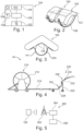
- the embodiment of the apparatus or sensor system 100 according to the invention shown in Fig. 1 comprises a vibration detector 102 connected to a controller unit 106 which in turn is connected to a communication unit 108.
- the vibration sensor is a piezo electric element provided with a weight or mass.
- the sensitivity and frequency response of the sensor can be configured by controlling the mass of the weight, dampening and other properties of the vibration sensor.
- Other types of vibration sensors may also be used like accelerometers, gyroscopes, mems devices, etc.
- the vibration sensor is preferably tuned to capture vibrations in the range from 0 to 10 kHz, more preferably between 0 and 1 kHz.
- the sensor system may be configured to capture vibrations continuously, where presence of vibration above a certain threshold indicates fluid flow. This enables continuous detection of vibrations. Preferably, the sensor system captures vibrations at certain intervals, this to save electrical power for example if the sensor is battery powered.
- the sensor system may operate in a triggered mode where the system is notified by the vibration sensor of vibrations above certain amplitude, length, pattern, signature, frequency, interval or other property of the vibration. When the control unit is operated in an interrupt mode, occurrence of certain vibrations is triggering the control unit to perform some specific action. Triggered mode reduces power consumption and enables robust detection of changes in the fluid flow.
- the control unit may alternate between the modes of capturing vibrations to reduced measurements when equipment in stored and increased number of measurements for rapid warning of errors.
- Fig. 3 shows the sensor package attached to a pipe using attachment means in the form of bands.
- the sensor system also comprises an inclinometer to determine if the cart has fallen over.
- the senor can be a pressure sensor placed in a T-pipe, preferably inserted between the pipe 224 and the hose 214, alternatively the pipe 224 and the sprinkler 232. While this can work it introduces three more connections that each is a potential source of failure.
- the senor can be embedded in or mounted on the inside of the pipe, a connection, a T-pipe or other part of the system to measure vibrations for detection of fluid flow. This is beneficial for simplifying installation of the system and removing the need for clamping the sensor onto a part of the system.
- the sensor may also be embedded such that it is in contact with the water flow and thereby also may measure temperature, pressure and other properties of the water stream.
- the sensor system then will charge for a while until enough energy to transmit and then discharge the stored energy when reporting.
- the communication system 300 comprises a communication transceiver 302 which allows transmission of data to the sensor system.
- This can be software upgrades, parameters such as reporting frequencies, configurations and more.
- the senor is used to detect water flow in fire hoses used during fire fighting.
- the sensor can be attached to the fire hoses, nozzles, fire hydrants and other parts of the water distribution network.
- the sensors can be rapidly be deployed to the equipment during firefighting to monitor equipment, detect leakages.
- the sensor may also be used on sprinkler installation to detect leakage, if water is delivered to the appropriate area, monitor for correct amount of water flowing though the system.
- the senor is used to monitor water flow to a snow canon when it is making snow.
- the sensor is advantageous in allowing detection of changes in the water flow to the snow canon, especially in the noisy environment in the proximity of the snow canon.
- the senor is attached to a part, such as a concrete padding, that is only temporarily in contact with the hose where water is passing through. This can be when the hose is winded in and the hose slams or hits the part. These slams or hits by the hose can be detected by the sensor as vibrations, shocks, impulses, or sounds.
- the invention according to the application finds use in agricultural watering but also in non-invasive determination of fluid flows including but not limited to oil, gas, fuel, and cooling water.
Landscapes
- Physics & Mathematics (AREA)
- Fluid Mechanics (AREA)
- Environmental Sciences (AREA)
- Engineering & Computer Science (AREA)
- Life Sciences & Earth Sciences (AREA)
- Water Supply & Treatment (AREA)
- General Physics & Mathematics (AREA)
- Electromagnetism (AREA)
- Chemical & Material Sciences (AREA)
- Analytical Chemistry (AREA)
- Indicating Or Recording The Presence, Absence, Or Direction Of Movement (AREA)
- Examining Or Testing Airtightness (AREA)
- Measuring Volume Flow (AREA)
Claims (4)
- System (100) zum Erfassen von Flüssigkeitsströmung in einem Schlauch oder Rohr (224, 214) eines Bewässerungssystems (200), wobei das Bewässerungssystem (200) Folgendes umfasst:den Schlauch und eine Trommel für den Schlauch; undeinen Sprinklerwagen, wobei das Rohr den Schlauch mit einer Sprinkleranordnung des Bewässerungssystems verbindet, die einen Sprinkler zum Verteilen von durch den Schlauch fließendem Wasser und einen Ticker zum Verwenden von Energie aus dem durch den Schlauch fließenden Wasser zum Drehen des Sprinklers umfasst,das System (100) zum Erfassen von Flüssigkeitsströmung, umfassend ein Sensorsystem, das mindestens einen Sensor (102, 104) zum Registrieren des Vorhandenseins von Vibrationen umfasst, wobei der mindestens eine Sensor an mindestens einem Element, ausgewählt aus einer Gruppe umfassend den Schlauch oder das Rohr (224, 214) und eine Struktur (210, 220) in mechanischer Verbindung mit dem Schlauch oder dem Rohr (224, 214),angebracht ist, und wobei das Sensorsystem dazu konfiguriert ist, durch den Ticker verursachte Vibrationsmuster zu erfassen und ein Intervall zwischen Ticks von dem Ticker zu bestimmen.
- System (100) nach Anspruch 1, umfassend ein Sensorpaket (120), das den Vibrationssensor, ein Gehäuse und Befestigungsmittel zur Befestigung des Gehäuses an dem Schlauch oder Rohr enthält, sodass ein Kontaktbereich des Gehäuses den Schlauch oder das Rohr berührt.
- System (100) nach einem der Ansprüche 1 und 2, wobei das Bewässerungssystem (200) ferner ein zweites System zum Messen von Flüssigkeitsströmung umfasst, das an der Schlauchtrommeleinheit (210) angebracht ist.
- System (100) nach einem der Ansprüche 1 bis 3, wobei der Vibrationssensor ein Mikrofon (104) zum Erfassen von durch den Ticker (234) verursachtem Lärm ist.
Applications Claiming Priority (2)
| Application Number | Priority Date | Filing Date | Title |
|---|---|---|---|
| NO20161986A NO20161986A1 (en) | 2016-12-14 | 2016-12-14 | Flow meter |
| PCT/NO2017/050328 WO2018111117A1 (en) | 2016-12-14 | 2017-12-14 | A system for detecting fluid flow in a fluid communicating device and a watering system comprising a fluid flow detecting system |
Publications (4)
| Publication Number | Publication Date |
|---|---|
| EP3554221A1 EP3554221A1 (de) | 2019-10-23 |
| EP3554221A4 EP3554221A4 (de) | 2020-07-22 |
| EP3554221B1 true EP3554221B1 (de) | 2025-04-16 |
| EP3554221C0 EP3554221C0 (de) | 2025-04-16 |
Family
ID=62559044
Family Applications (1)
| Application Number | Title | Priority Date | Filing Date |
|---|---|---|---|
| EP17881896.9A Active EP3554221B1 (de) | 2016-12-14 | 2017-12-14 | System zur erkennung des flüssigkeitsflusses in einer flüssigkeitsübertragungsvorrichtung und bewässerungssystem mit einem flüssigkeitsflusserkennungssystem |
Country Status (4)
| Country | Link |
|---|---|
| US (1) | US20200023395A1 (de) |
| EP (1) | EP3554221B1 (de) |
| NO (1) | NO20161986A1 (de) |
| WO (1) | WO2018111117A1 (de) |
Families Citing this family (9)
| Publication number | Priority date | Publication date | Assignee | Title |
|---|---|---|---|---|
| DE102018118112A1 (de) * | 2018-07-26 | 2020-01-30 | Minimax Gmbh & Co. Kg | Löschdüse, Feuerlöscheinrichtung und Brandschutzsystem mit Energy Harvesting |
| CA3183142C (en) * | 2020-05-14 | 2023-07-04 | Heartland Ag Tech, Inc. | Predictive maintenance systems and methods to determine end gun health |
| CN111735607B (zh) * | 2020-07-29 | 2024-06-14 | 交通运输部天津水运工程科学研究所 | 一种旋流检测系统及方法 |
| BR112023001442A2 (pt) * | 2020-07-30 | 2023-04-11 | Valmont Industries | Métodos para monitorar um canhão de extremidade dentro de um sistema de irrigação |
| US11490576B2 (en) * | 2020-12-22 | 2022-11-08 | Heartland Ag Tech, Inc. | Modular kinematic and telemetry system for an irrigation system |
| AU2021410745B2 (en) | 2020-12-23 | 2023-07-20 | Heartland Ag Tech, Inc. | Condition based monitoring of irrigation |
| WO2022147530A1 (en) | 2021-01-04 | 2022-07-07 | Heartland Ag Tech, Inc. | Determining drive system anamalolies based on power and/or current changes in an irrigation system |
| US11859620B1 (en) | 2021-02-12 | 2024-01-02 | State Farm Mutual Automobile Insurance Company | Detecting and utilizing water vibrations in sump pump system control |
| CA3245896A1 (en) | 2022-03-31 | 2023-10-05 | Heartland Ag Tech, Inc. | IRRIGATION SYSTEM INCLUDING THE INTEGRATION OF AN INDEPENDENT ELECTRONIC OBSERVER WITH THE FERTIGATION SYSTEM |
Family Cites Families (13)
| Publication number | Priority date | Publication date | Assignee | Title |
|---|---|---|---|---|
| US3580092A (en) * | 1969-12-23 | 1971-05-25 | Scarpa Lab Inc | Acoustic flowmeter |
| US4186881A (en) * | 1978-11-09 | 1980-02-05 | Long Mfg. N. C., Inc. | Irrigation machine |
| US5287884A (en) * | 1992-07-24 | 1994-02-22 | Cohen Jeffrey D | Water flow monitoring system for determining the presence of leaks and stopping flow in plumbing pipes |
| US6567006B1 (en) * | 1999-11-19 | 2003-05-20 | Flow Metrix, Inc. | Monitoring vibrations in a pipeline network |
| DE10012926C2 (de) * | 2000-03-16 | 2002-01-31 | Daimler Chrysler Ag | Sensoreinrichtung zur Strömungsmessung, Vorrichtung zur Durchströmung mit einem Medium und Verfahren zur Bestimmung von Strömungsparametern |
| US20020073768A1 (en) * | 2000-09-01 | 2002-06-20 | Joynes George Malcolm Swift | Fluid flow sensors & leak detection systems |
| US7311004B2 (en) * | 2003-03-10 | 2007-12-25 | Capstan Ag Systems, Inc. | Flow control and operation monitoring system for individual spray nozzles |
| WO2011052866A1 (ko) * | 2009-10-30 | 2011-05-05 | 주식회사 에이앤디코퍼레이션 | 비절단식 유량 변화 감지기 및 이를 포함하는 디스펜싱 시스템 |
| US8665101B2 (en) * | 2009-11-16 | 2014-03-04 | Aquarius Spectrum Ltd. | System method and device for leak detection and localization in a pipe network |
| US9335297B1 (en) * | 2012-02-24 | 2016-05-10 | WaterTally, Inc. | Flow sensing device |
| IL228237A0 (en) * | 2013-06-17 | 2014-03-31 | Aqua Rimat Ltd | Monitoring and control of water and gas flow |
| WO2015134715A2 (en) * | 2014-03-07 | 2015-09-11 | Lagoon Systems, Inc. | Systems and methods for non-invasive fluid flow measurement |
| GB2519643A (en) * | 2014-08-23 | 2015-04-29 | Kamran Iqbal | Flow monitor |
-
2016
- 2016-12-14 NO NO20161986A patent/NO20161986A1/en unknown
-
2017
- 2017-12-14 US US16/470,170 patent/US20200023395A1/en not_active Abandoned
- 2017-12-14 WO PCT/NO2017/050328 patent/WO2018111117A1/en not_active Ceased
- 2017-12-14 EP EP17881896.9A patent/EP3554221B1/de active Active
Also Published As
| Publication number | Publication date |
|---|---|
| WO2018111117A1 (en) | 2018-06-21 |
| US20200023395A1 (en) | 2020-01-23 |
| NO20161986A1 (en) | 2018-06-15 |
| EP3554221A4 (de) | 2020-07-22 |
| EP3554221A1 (de) | 2019-10-23 |
| EP3554221C0 (de) | 2025-04-16 |
Similar Documents
| Publication | Publication Date | Title |
|---|---|---|
| EP3554221B1 (de) | System zur erkennung des flüssigkeitsflusses in einer flüssigkeitsübertragungsvorrichtung und bewässerungssystem mit einem flüssigkeitsflusserkennungssystem | |
| WO2012156966A1 (en) | Method and system for identifying leaks in liquid pipe construction | |
| KR101174367B1 (ko) | 배관 인입형 누출감지장치 및 이를 이용한 배관의 누출감지 시스템 | |
| US20060191341A1 (en) | Ultrasonic gas leak detector including a detector testing device | |
| US6940409B1 (en) | Fluid flow detector | |
| KR101794968B1 (ko) | 소화전을 이용한 상수도의 누수감지장치 | |
| TW200744708A (en) | Fire suppression system | |
| WO2016139442A1 (en) | An ultrasonic water meter and a standpipe incorporating same | |
| WO2009019870A1 (ja) | 流量計測装置、通信システム、流量計測方法、流量計測プログラム、流体供給システムおよびガス器具監視装置 | |
| CN110924476A (zh) | 一种带水流量测量功能的智能消火栓及水流量测量方法 | |
| US20230172124A1 (en) | System for detecting fluid flow in a fluid communicating device and a watering system comprising a fluid flow detecting system | |
| US20210003243A1 (en) | System and method for locating leaks in pipelines | |
| JP7406222B2 (ja) | 漏洩検知方法 | |
| CN2918969Y (zh) | 管道泄漏监测定位报警系统 | |
| US7084778B2 (en) | Ammonia flow alarm and method therefor | |
| CN108601965A (zh) | 喷雾灭火设备 | |
| JP6415832B2 (ja) | スプリンクラ消火設備 | |
| US20230122613A1 (en) | Apparatus and method of remote sensing | |
| GB2516879A (en) | Fire suppression system | |
| KR101539363B1 (ko) | 해상의 스파구조물에 설치되는 공중 음파 감지 장치 | |
| US11686408B2 (en) | Non-invasive pipeline pig signal using vibration sensors | |
| CN216536702U (zh) | 一种用于消防水泵接合器的检测装置 | |
| WO2026052928A1 (en) | A mounting arrangement and a sensing arrangement for a fluid pipe | |
| JP3060192B2 (ja) | スプリンクラ消火設備の流水判別装置 | |
| KR101512756B1 (ko) | 파이프 내에서 이동하는 피그를 감지하는 피그 감지기 |
Legal Events
| Date | Code | Title | Description |
|---|---|---|---|
| STAA | Information on the status of an ep patent application or granted ep patent |
Free format text: STATUS: THE INTERNATIONAL PUBLICATION HAS BEEN MADE |
|
| PUAI | Public reference made under article 153(3) epc to a published international application that has entered the european phase |
Free format text: ORIGINAL CODE: 0009012 |
|
| STAA | Information on the status of an ep patent application or granted ep patent |
Free format text: STATUS: REQUEST FOR EXAMINATION WAS MADE |
|
| 17P | Request for examination filed |
Effective date: 20190715 |
|
| AK | Designated contracting states |
Kind code of ref document: A1 Designated state(s): AL AT BE BG CH CY CZ DE DK EE ES FI FR GB GR HR HU IE IS IT LI LT LU LV MC MK MT NL NO PL PT RO RS SE SI SK SM TR |
|
| AX | Request for extension of the european patent |
Extension state: BA ME |
|
| DAV | Request for validation of the european patent (deleted) | ||
| DAX | Request for extension of the european patent (deleted) | ||
| A4 | Supplementary search report drawn up and despatched |
Effective date: 20200618 |
|
| RIC1 | Information provided on ipc code assigned before grant |
Ipc: G01M 3/00 20060101ALI20200612BHEP Ipc: A01G 25/09 20060101AFI20200612BHEP Ipc: G01F 1/66 20060101ALI20200612BHEP Ipc: G01F 1/00 20060101ALI20200612BHEP |
|
| STAA | Information on the status of an ep patent application or granted ep patent |
Free format text: STATUS: EXAMINATION IS IN PROGRESS |
|
| 17Q | First examination report despatched |
Effective date: 20230707 |
|
| GRAP | Despatch of communication of intention to grant a patent |
Free format text: ORIGINAL CODE: EPIDOSNIGR1 |
|
| STAA | Information on the status of an ep patent application or granted ep patent |
Free format text: STATUS: GRANT OF PATENT IS INTENDED |
|
| INTG | Intention to grant announced |
Effective date: 20241107 |
|
| RAP3 | Party data changed (applicant data changed or rights of an application transferred) |
Owner name: 7SENSE AGRITECH AS |
|
| GRAS | Grant fee paid |
Free format text: ORIGINAL CODE: EPIDOSNIGR3 |
|
| GRAA | (expected) grant |
Free format text: ORIGINAL CODE: 0009210 |
|
| STAA | Information on the status of an ep patent application or granted ep patent |
Free format text: STATUS: THE PATENT HAS BEEN GRANTED |
|
| AK | Designated contracting states |
Kind code of ref document: B1 Designated state(s): AL AT BE BG CH CY CZ DE DK EE ES FI FR GB GR HR HU IE IS IT LI LT LU LV MC MK MT NL NO PL PT RO RS SE SI SK SM TR |
|
| REG | Reference to a national code |
Ref country code: GB Ref legal event code: FG4D |
|
| REG | Reference to a national code |
Ref country code: CH Ref legal event code: EP Ref country code: DE Ref legal event code: R096 Ref document number: 602017088995 Country of ref document: DE |
|
| REG | Reference to a national code |
Ref country code: IE Ref legal event code: FG4D |
|
| U01 | Request for unitary effect filed |
Effective date: 20250513 |
|
| U07 | Unitary effect registered |
Designated state(s): AT BE BG DE DK EE FI FR IT LT LU LV MT NL PT RO SE SI Effective date: 20250519 |
|
| PG25 | Lapsed in a contracting state [announced via postgrant information from national office to epo] |
Ref country code: ES Free format text: LAPSE BECAUSE OF FAILURE TO SUBMIT A TRANSLATION OF THE DESCRIPTION OR TO PAY THE FEE WITHIN THE PRESCRIBED TIME-LIMIT Effective date: 20250416 |
|
| PG25 | Lapsed in a contracting state [announced via postgrant information from national office to epo] |
Ref country code: NO Free format text: LAPSE BECAUSE OF FAILURE TO SUBMIT A TRANSLATION OF THE DESCRIPTION OR TO PAY THE FEE WITHIN THE PRESCRIBED TIME-LIMIT Effective date: 20250716 Ref country code: GR Free format text: LAPSE BECAUSE OF FAILURE TO SUBMIT A TRANSLATION OF THE DESCRIPTION OR TO PAY THE FEE WITHIN THE PRESCRIBED TIME-LIMIT Effective date: 20250717 |
|
| PG25 | Lapsed in a contracting state [announced via postgrant information from national office to epo] |
Ref country code: PL Free format text: LAPSE BECAUSE OF FAILURE TO SUBMIT A TRANSLATION OF THE DESCRIPTION OR TO PAY THE FEE WITHIN THE PRESCRIBED TIME-LIMIT Effective date: 20250416 |
|
| PG25 | Lapsed in a contracting state [announced via postgrant information from national office to epo] |
Ref country code: HR Free format text: LAPSE BECAUSE OF FAILURE TO SUBMIT A TRANSLATION OF THE DESCRIPTION OR TO PAY THE FEE WITHIN THE PRESCRIBED TIME-LIMIT Effective date: 20250416 |
|
| PG25 | Lapsed in a contracting state [announced via postgrant information from national office to epo] |
Ref country code: RS Free format text: LAPSE BECAUSE OF FAILURE TO SUBMIT A TRANSLATION OF THE DESCRIPTION OR TO PAY THE FEE WITHIN THE PRESCRIBED TIME-LIMIT Effective date: 20250716 |
|
| PG25 | Lapsed in a contracting state [announced via postgrant information from national office to epo] |
Ref country code: IS Free format text: LAPSE BECAUSE OF FAILURE TO SUBMIT A TRANSLATION OF THE DESCRIPTION OR TO PAY THE FEE WITHIN THE PRESCRIBED TIME-LIMIT Effective date: 20250816 |
|
| PG25 | Lapsed in a contracting state [announced via postgrant information from national office to epo] |
Ref country code: SM Free format text: LAPSE BECAUSE OF FAILURE TO SUBMIT A TRANSLATION OF THE DESCRIPTION OR TO PAY THE FEE WITHIN THE PRESCRIBED TIME-LIMIT Effective date: 20250416 |
|
| U1N | Appointed representative for the unitary patent procedure changed after the registration of the unitary effect |
Representative=s name: ACAPO ONSAGERS AS; NO |
|
| PG25 | Lapsed in a contracting state [announced via postgrant information from national office to epo] |
Ref country code: CZ Free format text: LAPSE BECAUSE OF FAILURE TO SUBMIT A TRANSLATION OF THE DESCRIPTION OR TO PAY THE FEE WITHIN THE PRESCRIBED TIME-LIMIT Effective date: 20250416 |
|
| PG25 | Lapsed in a contracting state [announced via postgrant information from national office to epo] |
Ref country code: SK Free format text: LAPSE BECAUSE OF FAILURE TO SUBMIT A TRANSLATION OF THE DESCRIPTION OR TO PAY THE FEE WITHIN THE PRESCRIBED TIME-LIMIT Effective date: 20250416 |
|
| PLBE | No opposition filed within time limit |
Free format text: ORIGINAL CODE: 0009261 |
|
| STAA | Information on the status of an ep patent application or granted ep patent |
Free format text: STATUS: NO OPPOSITION FILED WITHIN TIME LIMIT |
|
| REG | Reference to a national code |
Ref country code: CH Ref legal event code: L10 Free format text: ST27 STATUS EVENT CODE: U-0-0-L10-L00 (AS PROVIDED BY THE NATIONAL OFFICE) Effective date: 20260225 |
|
| 26N | No opposition filed |
Effective date: 20260119 |