EP3554195A1 - Led light source - Google Patents
Led light source Download PDFInfo
- Publication number
- EP3554195A1 EP3554195A1 EP19162825.4A EP19162825A EP3554195A1 EP 3554195 A1 EP3554195 A1 EP 3554195A1 EP 19162825 A EP19162825 A EP 19162825A EP 3554195 A1 EP3554195 A1 EP 3554195A1
- Authority
- EP
- European Patent Office
- Prior art keywords
- converter
- light source
- led light
- controllable switch
- output terminal
- Prior art date
- Legal status (The legal status is an assumption and is not a legal conclusion. Google has not performed a legal analysis and makes no representation as to the accuracy of the status listed.)
- Withdrawn
Links
Images


Classifications
-
- H—ELECTRICITY
- H05—ELECTRIC TECHNIQUES NOT OTHERWISE PROVIDED FOR
- H05B—ELECTRIC HEATING; ELECTRIC LIGHT SOURCES NOT OTHERWISE PROVIDED FOR; CIRCUIT ARRANGEMENTS FOR ELECTRIC LIGHT SOURCES, IN GENERAL
- H05B45/00—Circuit arrangements for operating light-emitting diodes [LED]
- H05B45/30—Driver circuits
- H05B45/37—Converter circuits
-
- H—ELECTRICITY
- H05—ELECTRIC TECHNIQUES NOT OTHERWISE PROVIDED FOR
- H05B—ELECTRIC HEATING; ELECTRIC LIGHT SOURCES NOT OTHERWISE PROVIDED FOR; CIRCUIT ARRANGEMENTS FOR ELECTRIC LIGHT SOURCES, IN GENERAL
- H05B45/00—Circuit arrangements for operating light-emitting diodes [LED]
- H05B45/40—Details of LED load circuits
- H05B45/44—Details of LED load circuits with an active control inside an LED matrix
-
- H—ELECTRICITY
- H05—ELECTRIC TECHNIQUES NOT OTHERWISE PROVIDED FOR
- H05B—ELECTRIC HEATING; ELECTRIC LIGHT SOURCES NOT OTHERWISE PROVIDED FOR; CIRCUIT ARRANGEMENTS FOR ELECTRIC LIGHT SOURCES, IN GENERAL
- H05B45/00—Circuit arrangements for operating light-emitting diodes [LED]
- H05B45/30—Driver circuits
- H05B45/36—Circuits for reducing or suppressing harmonics, ripples or electromagnetic interferences [EMI]
-
- H—ELECTRICITY
- H05—ELECTRIC TECHNIQUES NOT OTHERWISE PROVIDED FOR
- H05B—ELECTRIC HEATING; ELECTRIC LIGHT SOURCES NOT OTHERWISE PROVIDED FOR; CIRCUIT ARRANGEMENTS FOR ELECTRIC LIGHT SOURCES, IN GENERAL
- H05B45/00—Circuit arrangements for operating light-emitting diodes [LED]
- H05B45/40—Details of LED load circuits
- H05B45/44—Details of LED load circuits with an active control inside an LED matrix
- H05B45/48—Details of LED load circuits with an active control inside an LED matrix having LEDs organised in strings and incorporating parallel shunting devices
-
- Y—GENERAL TAGGING OF NEW TECHNOLOGICAL DEVELOPMENTS; GENERAL TAGGING OF CROSS-SECTIONAL TECHNOLOGIES SPANNING OVER SEVERAL SECTIONS OF THE IPC; TECHNICAL SUBJECTS COVERED BY FORMER USPC CROSS-REFERENCE ART COLLECTIONS [XRACs] AND DIGESTS
- Y02—TECHNOLOGIES OR APPLICATIONS FOR MITIGATION OR ADAPTATION AGAINST CLIMATE CHANGE
- Y02B—CLIMATE CHANGE MITIGATION TECHNOLOGIES RELATED TO BUILDINGS, e.g. HOUSING, HOUSE APPLIANCES OR RELATED END-USER APPLICATIONS
- Y02B20/00—Energy efficient lighting technologies, e.g. halogen lamps or gas discharge lamps
- Y02B20/30—Semiconductor lamps, e.g. solid state lamps [SSL] light emitting diodes [LED] or organic LED [OLED]
-
- Y—GENERAL TAGGING OF NEW TECHNOLOGICAL DEVELOPMENTS; GENERAL TAGGING OF CROSS-SECTIONAL TECHNOLOGIES SPANNING OVER SEVERAL SECTIONS OF THE IPC; TECHNICAL SUBJECTS COVERED BY FORMER USPC CROSS-REFERENCE ART COLLECTIONS [XRACs] AND DIGESTS
- Y02—TECHNOLOGIES OR APPLICATIONS FOR MITIGATION OR ADAPTATION AGAINST CLIMATE CHANGE
- Y02B—CLIMATE CHANGE MITIGATION TECHNOLOGIES RELATED TO BUILDINGS, e.g. HOUSING, HOUSE APPLIANCES OR RELATED END-USER APPLICATIONS
- Y02B70/00—Technologies for an efficient end-user side electric power management and consumption
- Y02B70/10—Technologies improving the efficiency by using switched-mode power supplies [SMPS], i.e. efficient power electronics conversion e.g. power factor correction or reduction of losses in power supplies or efficient standby modes
Definitions
- the invention relates to the field of LED light sources. More in particular, the invention relates to LED light sources equipped with a standby function, in other words the operation of the LED light source can be stopped while the mains supply is still connected to it.
- LEDs are used on an increasing scale. LEDS have a high efficiency and a long life time. In many lighting systems, LEDs also offer a higher optical efficiency than other light sources. As a consequence, LEDs offer an interesting alternative for the well known light sources such as fluorescent lamps, high intensity discharge lamps or incandescent lamps.
- LED light sources are often comprised in a lighting system, wherein the operation of the LED light sources is controlled by control commands.
- control commands include commands for activating the LED light source and commands for stopping the operation of the LED light source, i.e. commands to start generating a LED current and commands to stop generating a LED current, respectively.
- operation is not stopped by interrupting the connection of the LED light source to the mains supply but by stopping for instance the operation of a converter circuit comprised in the LED light source.
- the LED light source is said to be in standby mode. In this standby mode, since the mains supply is still connected to the LED light source, the LED light source is still capable to receive further commands and process those commands.
- the mains supply may cause a leakage current through parasitic capacitances and (part of) the LED load comprised in the LED light source.
- This leakage current can cause the LED string to generate a small amount of light resulting in a glow effect that is often undesirable.
- a LED light source comprising:
- a current supplying the LEDs can flow through the current control element and also through the first controllable switch that is maintained in the conductive state.
- the LED current supplied to the LED load by the converter is stopped, the LED light source is in a standby state and the first controllable switch is rendered non-conductive.
- leakage currents flowing from the mains supply to the LED load via parasitic capacitances are effectively suppressed, so that the LEDs do not generate a small amount of light during the standby state.
- a method according to the invention effectively suppresses leakage currents that otherwise flow through the parasitic capacitances and cause the LED load to generate a small amount of light.
- the current control element is preferably implemented as a diode or a further controllable switch having a control electrode coupled to further control circuitry for rendering the further controllable switch non-conductive in case the LED light source is in standby mode.
- Both the current control element and the first controllable switch may comprise a FET or a relais.
- the control circuitry used for rendering the first controllable switch non-conductive in case the LED light source is in standby mode comprises a voltage divider comprising a series arrangement of a first resistor and a second resistor connecting the first converter output terminal to the second converter output terminal and a control electrode of the first controllable switch is coupled to a terminal between the first resistor and the second resistor.
- the first control circuitry is realized in a cheap and dependable way.
- the DC-DC-converter comprises a transformer equipped with a primary winding and a secondary winding and a capacitor is coupled between the primary winding and the secondary winding.
- the capacitor can be a separate component, for instance a capacitor for suppressing EMI.
- the capacitor can also be a parasitic capacitor.
- the transformer causes the LED light source to become an isolated LED light source.
- the transformer provides isolation between the LED load and the mains supply, due to the presence of the capacitor coupled between primary and secondary winding, the transformer does not sufficiently suppress leakage currents that flow from the mains supply through parasitic capacitances and through the LEDs to prevent that the LEDs generate a small amount of light.
- the present invention also effectively suppresses leakage currents in isolated LED light sources in case they are in the standby state.
- the standby mode is entered by stopping the operation of the DC-DC converter, and the control circuitry for rendering the first controllable switch non-conductive in case the LED light source is in standby mode, is comprised in a converter control circuit comprised in the DC-DC converter, and the control electrode of the first controllable switch is coupled to an output terminal of the converter control circuit.
- the first controllable switch needs to be rendered conductive when the operation of the DC-DC converter is stopped, it is efficient to control both the operation of the DC-DC converter and the conductive state of the first controllable switch, using the converter control circuit of the DC-DC converter.
- the standby mode is entered by stopping the operation of the DC-DC converter, and the further control circuitry used for rendering the further controllable switch non-conductive in case the LED light source is in standby mode, is comprised in a converter control circuit comprised in the DC-DC converter, and the control electrode of the further controllable switch is coupled to a second output terminal of the converter control circuit.
- the further controllable switch needs to be rendered conductive when the operation of the DC-DC converter is stopped, it is efficient to control both the operation of the DC-DC converter and the conductive state of the further controllable switch, using the converter control circuit of the DC-DC converter.
- K1 and K2 are input terminals for connection to a mains supply source.
- Diodes D1-D4 form a rectifier RB comprising rectifier output terminals.
- the rectifier output terminals are connected to respective converter input terminals of a DC-DC converter CONV for generating a DC-current out of the rectified mains supply voltage.
- the converter CONV comprises a first converter output terminal A and a second converter output terminal B.
- the converter input terminals are connected by means of a capacitor Cin and the first and second converter output terminals are connected by means of a capacitor Cout.
- Converter CONV is equipped with an input terminal K3 for receiving a control signal that activates or stops the operation of a converter control circuit comprised in the DC-DC converter and thereby, respectively, starts the operation of the LED light source or causes the LED light source to go into standby mode.
- the control signal can for instance be generated by light control circuitry in a lighting system of which the LED light source forms part.
- the first converter output terminal A is connected to an anode of a LED load LL.
- the LED load LL is schematically represented by two LEDs, LED1 and LED2. In practice, the LED load will generally comprise a far higher number of LEDs.
- a cathode of the LED load LL is connected to the second converter output terminal B.
- the LED light source shown in Fig. 1 is very suitable to be used in a luminaire.
- a luminaire is usually connected to a protective earth PE, which in turn is connected to the "neutral" of the mains supply source.
- the inventor has found that the LED load often couples with the luminaire and thus also with the protective earth PE by means of parasitic capacitances.
- the parasitic capacitances are schematically represented in Fig. 1 as Cparl, Cpar2 and Cpar3.
- the mains supply voltage is rectified by rectifier RB, and DC-DC converter CONV generates, out of the rectified mains supply voltage, a DC current that is supplied to the LED load LL. This DC current causes the LEDs to generate light.
- a first current flows from terminal K2 through parasitic capacitance Cpar3 and diode D3 to input terminal K1.
- a second current flows from input terminal K2, through Cpar2, LED2 and diode D3 to input terminal K1.
- a third current flows from terminal K2, through parasitic capacitance Cpar1, capacitor Cout and diode D3 to input terminal K1.
- a current flows from terminal K1, through diode D1 and capacitor Cin to converter output terminal B.
- a first current flows through capacitor Cout and parasitic capacitance Cpar1 to input terminal K2.
- a second current flows from converter output terminal B through capacitor Cout, LED1 and parasitic capacitance Cpar2 to input terminal K2.
- a third current flows from converter output terminal B through parasitic capacitance Cpar3 to terminal K2.
- the leakage current thus flows through the parasitic capacitances and also partly through the LEDs and thereby causes the LEDs to generate a small amount of light that is considered undesirable.
- the LED light source shown in Fig. 2 differs from the prior art LED light source shown in Fig. 1 in that the LED light source of Fig. 2 further comprises resistors R1 and R2, diode D5, first controllable switch Ml and zener diode Zl.
- the first controllable switch is a FET.
- the converter output terminals of DC-DC converter CONV are connected by means of a series arrangement of resistor RI and resistor R2.
- a common terminal of resistor R1 and resistor R2 is connected to a control electrode of first controllable switch M1 and resistor R2 is shunted by zener diode Z1.
- Resistor R1, resistor R2 and zener diode Z1 together form first control circuitry for rendering the controllable switch Ml non-conductive in case the operation of the DC-DC converter is stopped and the LED light source is in standby mode.
- the normal operation of the LED light source shown in Fig. 2 is very similar to the normal operation of the prior art LED light source shown in Fig. 1 , since the diode D5 and the controllable switch M1 conduct the DC current generated by the DC-DC converter CONV.
- the operation of the DC-DC converter is stopped, the DC current supplying the LED load is no longer generated and the voltage between the converter output terminals decreases so that the first controllable switch M1 becomes non-conductive.
- Diode D5 and the body diode of controllable switch Ml block the leakage current, so that the parasitic capacitances are no longer charged and discharged, and the LEDs no longer generate a small amount of light, when the LED light source is in standby mode, so that the glow effect is effectively suppressed.
- the LEDs would still generate a small amount of light. This is because the LEDs would carry a reverse current flowing from their cathode to their anode for a high momentary magnitude of the mains voltage, when the voltage at terminal K2 is higher than the voltage at terminal K1. This current charges the parasitic capacitances. The LEDs would subsequently carry a current discharging the parasitic capacitances and flowing from their anode to their cathode in case the voltage at terminal K1 is higher than the voltage at terminal K2. In the embodiment shown in Fig. 2 , the reverse current flowing through the LEDs is blocked by diode D5.
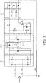
- the embodiment shown in Fig. 3 differs from that shown in Fig. 2 in that the DC-DC converter comprises a transformer T with a primary winding Lp and a secondary winding Ls.
- the primary winding Lp is connected to the secondary winding Ls by means of a capacitor C-EMI to suppress interference.
- the LED driver is an isolated LED driver, meaning that the circuitry and the LEDs on the secondary side of the transformer are isolated from the mains supply.
- the operation of the LED light source shown in Fig. 3 is very similar to that of the LED light source shown in Fig. 2 .
- the only difference is that in the standby state, the capacitor C-EMI will also be charged to a DC voltage.
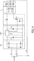
- the LED light source shown in Fig. 4 differs from the one shown in Fig. 2 in that resistors RI and R2 are dispensed with and that the conductive state of controllable switch Ml is controlled by a signal at a third output terminal of DC-DC converter CONY.
- the signal at this third output terminal renders the controllable switch M 1 non-conductive.
- the LED light source shown in Fig. 5 differs from that shown in Fig. 4 in that diode D5 has been replaced by a further controllable switch SW2.
- the FET forming the first controllable switch has been replaced by a more general symbol for the first controllable switch and zener diode Zl is dispensed with.
- the first controllable switch and the further controllable switch are controlled by means of, respectively, a signal present at a third output terminal and a signal present at a fourth output terminal of DC-DC-converter CONV.
- switches SW1 and SW2 are connected to, respectively, the third and the fourth output terminal of the DC-DC converter CONV.
- switches SW1 and SW2 are both rendered non-conductive.
- Switches SW1 and SW2 may be formed by any type of switch, such as a FETs or a relais or another type of switch. It is noted that in case one or both of the controllable switches are implemented by a relais, current conduction in both directions is blocked when the switch is rendered non-conductive. Also in this case an effective suppression of the leakage currents is realized.
Landscapes
- Circuit Arrangement For Electric Light Sources In General (AREA)
- Led Devices (AREA)
- Dc-Dc Converters (AREA)
Abstract
Description
- The invention relates to the field of LED light sources. More in particular, the invention relates to LED light sources equipped with a standby function, in other words the operation of the LED light source can be stopped while the mains supply is still connected to it.
- Lighting systems based on LEDs are used on an increasing scale. LEDS have a high efficiency and a long life time. In many lighting systems, LEDs also offer a higher optical efficiency than other light sources. As a consequence, LEDs offer an interesting alternative for the well known light sources such as fluorescent lamps, high intensity discharge lamps or incandescent lamps.
- LED light sources are often comprised in a lighting system, wherein the operation of the LED light sources is controlled by control commands. Such control commands include commands for activating the LED light source and commands for stopping the operation of the LED light source, i.e. commands to start generating a LED current and commands to stop generating a LED current, respectively. In the latter case, operation is not stopped by interrupting the connection of the LED light source to the mains supply but by stopping for instance the operation of a converter circuit comprised in the LED light source. In this latter case, the LED light source is said to be in standby mode. In this standby mode, since the mains supply is still connected to the LED light source, the LED light source is still capable to receive further commands and process those commands. At the same time, however, the mains supply may cause a leakage current through parasitic capacitances and (part of) the LED load comprised in the LED light source. This leakage current can cause the LED string to generate a small amount of light resulting in a glow effect that is often undesirable.
- It is an object of the invention to provide a LED light source that does not generate a small amount of light caused by leakage currents when it is in standby mode.
- According to a first aspect of the invention, a LED light source is provided, comprising:
- input terminals for connection to a mains voltage supply source,
- a rectifier coupled to the input terminals for rectifying the mains supply voltage supplied by the mains supply voltage source and comprising rectifier output terminals,
- a DC-DC-converter for generating a DC current out of the rectified mains supply voltage, comprising converter input terminals connected to the rectifier output terminals and comprising a first converter output terminal and a second converter output terminal,
- During operation, a current supplying the LEDs can flow through the current control element and also through the first controllable switch that is maintained in the conductive state. In case the LED current supplied to the LED load by the converter is stopped, the LED light source is in a standby state and the first controllable switch is rendered non-conductive. As a result, leakage currents flowing from the mains supply to the LED load via parasitic capacitances are effectively suppressed, so that the LEDs do not generate a small amount of light during the standby state.
- According to a further aspect of the invention, a method is provided for suppressing the leakage current through the LED load of a LED light source during standby, said LED light source comprising:
- a rectifier for connection to the mains supply and for rectifying a mains supply voltage,
- a LED load, and
- a DC-DC-converter coupled between the rectifier and the LED load,
- a protective earth terminal connected to the neutral of the mains supply and coupled to the LED load by means of parasitic capacitances,
- after the operation of the LED light source has stopped and the LED light source is in the standby mode,
- blocking the flow of current from an anode of the LED load to the rectifier by means of a current control element, and
- blocking the flow of current from a cathode of the LED load to the rectifier, by making a first controllable switch in the current path non-conductive.
- A method according to the invention effectively suppresses leakage currents that otherwise flow through the parasitic capacitances and cause the LED load to generate a small amount of light.
- The current control element is preferably implemented as a diode or a further controllable switch having a control electrode coupled to further control circuitry for rendering the further controllable switch non-conductive in case the LED light source is in standby mode. Both the current control element and the first controllable switch may comprise a FET or a relais.
- In a first preferred embodiment, the control circuitry used for rendering the first controllable switch non-conductive in case the LED light source is in standby mode, comprises a voltage divider comprising a series arrangement of a first resistor and a second resistor connecting the first converter output terminal to the second converter output terminal and a control electrode of the first controllable switch is coupled to a terminal between the first resistor and the second resistor.
- In case the operation of the DC-DC-converter is stopped because the LED light source is going into standby mode, the voltage between the converter output terminals decreases, so that also the voltage at the control electrode of the controllable switch drops to a voltage so low that the first controllable switch becomes non-conductive.
- In this way, the first control circuitry is realized in a cheap and dependable way.
- In a further preferred embodiment, the DC-DC-converter comprises a transformer equipped with a primary winding and a secondary winding and a capacitor is coupled between the primary winding and the secondary winding.
- The capacitor can be a separate component, for instance a capacitor for suppressing EMI. The capacitor can also be a parasitic capacitor.
- The transformer causes the LED light source to become an isolated LED light source. Although the transformer provides isolation between the LED load and the mains supply, due to the presence of the capacitor coupled between primary and secondary winding, the transformer does not sufficiently suppress leakage currents that flow from the mains supply through parasitic capacitances and through the LEDs to prevent that the LEDs generate a small amount of light. However, it has been found that the present invention also effectively suppresses leakage currents in isolated LED light sources in case they are in the standby state.
- In another preferred embodiment of a LED light source according to the invention, the standby mode is entered by stopping the operation of the DC-DC converter, and the control circuitry for rendering the first controllable switch non-conductive in case the LED light source is in standby mode, is comprised in a converter control circuit comprised in the DC-DC converter, and the control electrode of the first controllable switch is coupled to an output terminal of the converter control circuit.
- Since the first controllable switch needs to be rendered conductive when the operation of the DC-DC converter is stopped, it is efficient to control both the operation of the DC-DC converter and the conductive state of the first controllable switch, using the converter control circuit of the DC-DC converter.
- In yet another preferred embodiment of a LED light source according to the invention, the standby mode is entered by stopping the operation of the DC-DC converter, and the further control circuitry used for rendering the further controllable switch non-conductive in case the LED light source is in standby mode, is comprised in a converter control circuit comprised in the DC-DC converter, and the control electrode of the further controllable switch is coupled to a second output terminal of the converter control circuit.
- Since also the further controllable switch needs to be rendered conductive when the operation of the DC-DC converter is stopped, it is efficient to control both the operation of the DC-DC converter and the conductive state of the further controllable switch, using the converter control circuit of the DC-DC converter.
- These and other aspects of the invention will be apparent from and elucidated with reference to the embodiments described hereinafter.
- In the drawings:
-
Fig. 1 shows a schematic representation of an embodiment of a LED light source according to the prior art, and -
Figs. 2-5 respectively show schematic representations of a first, second and third embodiment of a LED light source according to the invention. - In
Fig. 1 , K1 and K2 are input terminals for connection to a mains supply source. Diodes D1-D4 form a rectifier RB comprising rectifier output terminals. The rectifier output terminals are connected to respective converter input terminals of a DC-DC converter CONV for generating a DC-current out of the rectified mains supply voltage. The converter CONV comprises a first converter output terminal A and a second converter output terminal B. The converter input terminals are connected by means of a capacitor Cin and the first and second converter output terminals are connected by means of a capacitor Cout. - Converter CONV is equipped with an input terminal K3 for receiving a control signal that activates or stops the operation of a converter control circuit comprised in the DC-DC converter and thereby, respectively, starts the operation of the LED light source or causes the LED light source to go into standby mode. The control signal can for instance be generated by light control circuitry in a lighting system of which the LED light source forms part.
- The first converter output terminal A is connected to an anode of a LED load LL. In
Fig. 1 , the LED load LL is schematically represented by two LEDs, LED1 and LED2. In practice, the LED load will generally comprise a far higher number of LEDs. A cathode of the LED load LL is connected to the second converter output terminal B. - The LED light source shown in
Fig. 1 is very suitable to be used in a luminaire. For safety reasons such a luminaire is usually connected to a protective earth PE, which in turn is connected to the "neutral" of the mains supply source. The inventor has found that the LED load often couples with the luminaire and thus also with the protective earth PE by means of parasitic capacitances. The parasitic capacitances are schematically represented inFig. 1 as Cparl, Cpar2 and Cpar3. - During normal operation of the LED light source shown in
Fig. 1 , the mains supply voltage is rectified by rectifier RB, and DC-DC converter CONV generates, out of the rectified mains supply voltage, a DC current that is supplied to the LED load LL. This DC current causes the LEDs to generate light. - However, in case a control signal that stops the operation of the DC-DC converter is received at terminal K3, the DC current that flows through the LEDs is no longer generated and the LED light source is in standby mode.
- Since the input terminals of the LED light source are still connected to the mains supply source, the parasitic capacitances coupling the protective earth to the LED load cause an AC leakage current to flow.
- In case the voltage at terminal K2 is higher than the voltage at terminal K1, a first current flows from terminal K2 through parasitic capacitance Cpar3 and diode D3 to input terminal K1. A second current flows from input terminal K2, through Cpar2, LED2 and diode D3 to input terminal K1. A third current flows from terminal K2, through parasitic capacitance Cpar1, capacitor Cout and diode D3 to input terminal K1. These currents charge the parasitic capacitances.
- In case the voltage at input terminal K1 is higher than that at input terminal K2, a current flows from terminal K1, through diode D1 and capacitor Cin to converter output terminal B. From converter output terminal B a first current flows through capacitor Cout and parasitic capacitance Cpar1 to input terminal K2. A second current flows from converter output terminal B through capacitor Cout, LED1 and parasitic capacitance Cpar2 to input terminal K2. A third current flows from converter output terminal B through parasitic capacitance Cpar3 to terminal K2. These currents discharge the parasitic capacitances.
- The leakage current thus flows through the parasitic capacitances and also partly through the LEDs and thereby causes the LEDs to generate a small amount of light that is considered undesirable.
- The LED light source shown in
Fig. 2 differs from the prior art LED light source shown inFig. 1 in that the LED light source ofFig. 2 further comprises resistors R1 and R2, diode D5, first controllable switch Ml and zener diode Zl. In the embodiment shown inFig. 2 , the first controllable switch is a FET. The converter output terminals of DC-DC converter CONV are connected by means of a series arrangement of resistor RI and resistor R2. A common terminal of resistor R1 and resistor R2 is connected to a control electrode of first controllable switch M1 and resistor R2 is shunted by zener diode Z1. Resistor R1, resistor R2 and zener diode Z1 together form first control circuitry for rendering the controllable switch Ml non-conductive in case the operation of the DC-DC converter is stopped and the LED light source is in standby mode. - During normal operation of the LED light source shown in
Fig. 2 , the voltage across capacitor Cout and thus across the series arrangement of resistor R1 and resistor R2 is high enough to maintain the first controllable switch M1 in a conductive state. As a consequence, the normal operation of the LED light source shown inFig. 2 is very similar to the normal operation of the prior art LED light source shown inFig. 1 , since the diode D5 and the controllable switch M1 conduct the DC current generated by the DC-DC converter CONV. - In case the DC-DC converter receives a control signal at its terminal K3 to change from normal operation to standby mode, the operation of the DC-DC converter is stopped, the DC current supplying the LED load is no longer generated and the voltage between the converter output terminals decreases so that the first controllable switch M1 becomes non-conductive. Diode D5 and the body diode of controllable switch Ml block the leakage current, so that the parasitic capacitances are no longer charged and discharged, and the LEDs no longer generate a small amount of light, when the LED light source is in standby mode, so that the glow effect is effectively suppressed.
- It is noted that in case the diode D5 were dispensed with, the LEDs would still generate a small amount of light. This is because the LEDs would carry a reverse current flowing from their cathode to their anode for a high momentary magnitude of the mains voltage, when the voltage at terminal K2 is higher than the voltage at terminal K1. This current charges the parasitic capacitances. The LEDs would subsequently carry a current discharging the parasitic capacitances and flowing from their anode to their cathode in case the voltage at terminal K1 is higher than the voltage at terminal K2. In the embodiment shown in
Fig. 2 , the reverse current flowing through the LEDs is blocked by diode D5. - The embodiment shown in
Fig. 3 differs from that shown inFig. 2 in that the DC-DC converter comprises a transformer T with a primary winding Lp and a secondary winding Ls. The primary winding Lp is connected to the secondary winding Ls by means of a capacitor C-EMI to suppress interference. Because of the presence of the transformer, the LED driver is an isolated LED driver, meaning that the circuitry and the LEDs on the secondary side of the transformer are isolated from the mains supply. - The operation of the LED light source shown in
Fig. 3 is very similar to that of the LED light source shown inFig. 2 . The only difference is that in the standby state, the capacitor C-EMI will also be charged to a DC voltage. - The LED light source shown in
Fig. 4 differs from the one shown inFig. 2 in that resistors RI and R2 are dispensed with and that the conductive state of controllable switch Ml is controlled by a signal at a third output terminal of DC-DC converter CONY. When the operation of the DC-DC converter is stopped and the LED light source is in standby mode, the signal at this third output terminal renders thecontrollable switch M 1 non-conductive. - The LED light source shown in
Fig. 5 differs from that shown inFig. 4 in that diode D5 has been replaced by a further controllable switch SW2. The FET forming the first controllable switch has been replaced by a more general symbol for the first controllable switch and zener diode Zl is dispensed with. The first controllable switch and the further controllable switch are controlled by means of, respectively, a signal present at a third output terminal and a signal present at a fourth output terminal of DC-DC-converter CONV. To this end, switches SW1 and SW2 are connected to, respectively, the third and the fourth output terminal of the DC-DC converter CONV. When the LED light source is in standby mode, the switches SW1 and SW2 are both rendered non-conductive. Switches SW1 and SW2 may be formed by any type of switch, such as a FETs or a relais or another type of switch. It is noted that in case one or both of the controllable switches are implemented by a relais, current conduction in both directions is blocked when the switch is rendered non-conductive. Also in this case an effective suppression of the leakage currents is realized. - While the invention has been illustrated and described in detail in the drawings and foregoing description, such illustration and description are to be considered illustrative or exemplary and not restrictive; the invention is not limited to the disclosed embodiments. Other variations to the disclosed embodiments can be understood and effected by those skilled in the art in practicing the claimed invention, from a study of the drawings, the disclosure, and the appended claims. In the claims, the word "comprising" does not exclude other elements or steps, and the indefinite article "a" or "an" does not exclude a plurality. The mere fact that certain measures are recited in mutually different dependent claims does not indicate that a combination of these measures cannot be used to advantage. Any reference signs in the claims should not be construed as limiting the scope.
-
- 1. A LED light source comprising:
- input terminals (K1, K2) for connection to a mains voltage supply source,
- a rectifier (RB) coupled to the input terminals for rectifying the mains supply voltage supplied by the mains supply voltage source and comprising rectifier output terminals,
- a DC-DC converter (CONV) for generating a DC current out of the rectified mains supply voltage, comprising converter input terminals connected to the rectifier output terminals and comprising a first converter output terminal (A) and a second converter output terminal (B),
- 2. A LED light source as in example 1, wherein the current control element is a diode (D5).
- 3. A LED light source as in example 1, wherein the current control element is a further controllable switch (SW2) having a control electrode coupled to further control circuitry for rendering the further controllable switch non-conductive in case the LED light source is in standby mode.
- 4. A LED light source as in example 1, wherein the first controllable switch comprises a FET.
- 5. A LED light source as in example 3, wherein the further controllable switch comprises a FET.
- 6. A LED light source as in example 3, wherein the first controllable switch and the current control element each comprise a relais.
- 7. A LED light source as in example 1, wherein the first control circuitry comprises a voltage divider comprising a series arrangement of a first resistor (R1) and a second resistor (R2) connecting the first converter output terminal to the second converter output terminal and a control electrode of the controllable switch is coupled to a terminal between the first resistor and the second resistor.
- 8. A LED light source as in example 1, wherein the DC-DC converter comprises a transformer (T) equipped with a primary winding (Lp) and a secondary winding (Ls) and a capacitor (C_EMI) is coupled between the primary winding and the secondary winding.
- 9. A LED light source as in example 1, wherein the standby mode is entered by stopping the operation of the DC-DC converter, and wherein the control circuitry, for rendering the first controllable switch non-conductive in case the LED light source is in standby mode, is comprised in a converter control circuit comprised in the DC-DC converter and the control electrode of the first controllable switch is coupled to an output terminal of the converter control circuit.
- 10. A LED light source as in example 3, wherein the standby mode is entered by stopping the operation of the DC-DC converter, and wherein the further control circuitry for rendering the further controllable switch non-conductive in case the LED light source is in standby mode, is comprised in a converter control circuit comprised in the DC- DC converter and the control electrode of the further controllable switch is coupled to a second output terminal of the converter control circuit.
- 11. An example of a method of decreasing the leakage current through the LED load of a LED light source during standby, comprising:
- a rectifier for connection to the mains supply and for rectifying a mains supply voltage,
- a LED load, and
- a DC-DC converter coupled between the rectifier and the LED load,
- a protective earth terminal connected during operation to the neutral of the mains supply and coupled to the LED load by means of parasitic capacitances,
the method comprising the following steps:
after the operation of the DC-DC converter has stopped and the LED light source is in the standby mode, - blocking the flow of current from an anode of the LED load to the rectifier by means of a unidirectional element, and
- blocking the flow of current from a cathode of the LED load to the rectifier, by making a controllable switch in the current path non-conductive.
Claims (10)
- A LED light source comprising:- input terminals (K1, K2) for connection to a mains voltage supply source,- a rectifier (RB) coupled to the input terminals for rectifying the mains supply voltage supplied by the mains supply voltage source and comprising rectifier output terminals,- a DC-DC converter (CONV) for generating a DC current out of the rectified mains supply voltage, comprising converter input terminals connected to the rectifier output terminals and comprising a first converter output terminal (A) and a second converter output terminal (B),- a further terminal (K3) arranged to receive a control signal to change operation of the DC-DC converter (CONV) from a normal operation mode to a standby mode,- a LED load (LL) with an anode coupled to the first converter output terminal via a current control element (D5) for blocking a current flowing from the anode of the LED load to the first converter output terminal, and with a cathode coupled to the second converter output terminal via a first controllable switch (Ml) having a control electrode coupled to first control circuitry for rendering the controllable switch non-conductive in case the LED light source is in standby mode.
- A LED light source as in claim 1, wherein the current control element is a diode (D5).
- A LED light source as in claim 1, wherein the current control element is a further controllable switch (SW2) having a control electrode coupled to further control circuitry for rendering the further controllable switch non-conductive in case the LED light source is in standby mode.
- A LED light source as in claim 1, wherein the first controllable switch comprises a FET.
- A LED light source as in claim 3, wherein the further controllable switch comprises a FET.
- A LED light source as in claim 3, wherein the first controllable switch and the current control element each comprise a relais.
- A LED light source as in claim 1, wherein the first control circuitry comprises a voltage divider comprising a series arrangement of a first resistor (RI) and a second resistor (R2) connecting the first converter output terminal to the second converter output terminal and a control electrode of the controllable switch is coupled to a terminal between the first resistor and the second resistor.
- A LED light source as in claim 1, wherein the DC-DC converter comprises a transformer (T) equipped with a primary winding (Lp) and a secondary winding (Ls) and a capacitor (C_EMI) is coupled between the primary winding and the secondary winding.
- A LED light source as in claim 1, wherein the standby mode is entered by stopping the operation of the DC-DC converter, and wherein the control circuitry, for rendering the first controllable switch non-conductive in case the LED light source is in standby mode, is comprised in a converter control circuit comprised in the DC-DC converter and the control electrode of the first controllable switch is coupled to an output terminal of the converter control circuit.
- A LED light source as in claim 3, wherein the standby mode is entered by stopping the operation of the DC-DC converter, and wherein the further control circuitry for rendering the further controllable switch non-conductive in case the LED light source is in standby mode, is comprised in a converter control circuit comprised in the DC- DC converter and the control electrode of the further controllable switch is coupled to a second output terminal of the converter control circuit.
Applications Claiming Priority (3)
| Application Number | Priority Date | Filing Date | Title |
|---|---|---|---|
| US201261608696P | 2012-03-09 | 2012-03-09 | |
| EP13717316.7A EP2823691B1 (en) | 2012-03-09 | 2013-02-22 | Led light source |
| PCT/IB2013/051437 WO2013132379A1 (en) | 2012-03-09 | 2013-02-22 | Led light source |
Related Parent Applications (1)
| Application Number | Title | Priority Date | Filing Date |
|---|---|---|---|
| EP13717316.7A Division EP2823691B1 (en) | 2012-03-09 | 2013-02-22 | Led light source |
Publications (1)
| Publication Number | Publication Date |
|---|---|
| EP3554195A1 true EP3554195A1 (en) | 2019-10-16 |
Family
ID=48142030
Family Applications (2)
| Application Number | Title | Priority Date | Filing Date |
|---|---|---|---|
| EP19162825.4A Withdrawn EP3554195A1 (en) | 2012-03-09 | 2013-02-22 | Led light source |
| EP13717316.7A Active EP2823691B1 (en) | 2012-03-09 | 2013-02-22 | Led light source |
Family Applications After (1)
| Application Number | Title | Priority Date | Filing Date |
|---|---|---|---|
| EP13717316.7A Active EP2823691B1 (en) | 2012-03-09 | 2013-02-22 | Led light source |
Country Status (9)
| Country | Link |
|---|---|
| US (1) | US9655176B2 (en) |
| EP (2) | EP3554195A1 (en) |
| JP (1) | JP6087960B2 (en) |
| CN (1) | CN104145529B (en) |
| DK (1) | DK2823691T3 (en) |
| ES (1) | ES2733752T3 (en) |
| PL (1) | PL2823691T3 (en) |
| TR (1) | TR201908521T4 (en) |
| WO (1) | WO2013132379A1 (en) |
Families Citing this family (12)
| Publication number | Priority date | Publication date | Assignee | Title |
|---|---|---|---|---|
| KR101360685B1 (en) * | 2012-05-31 | 2014-02-10 | 엘지이노텍 주식회사 | Illumination system reduced standby power |
| WO2014085837A2 (en) * | 2012-12-06 | 2014-06-12 | Tridonic Gmbh & Co Kg | Operating device for illuminant |
| CN106982493B (en) * | 2013-09-29 | 2019-01-18 | 赛尔富电子有限公司 | A kind of under-voltage protecting circuit for LED lamp |
| DE102015202370A1 (en) * | 2015-02-10 | 2016-08-11 | Osram Gmbh | Circuit arrangement for operating semiconductor light sources |
| JP6353992B1 (en) * | 2015-06-04 | 2018-07-04 | フィリップス ライティング ホールディング ビー ヴィ | LED light source with improved glow reduction |
| US9942953B2 (en) * | 2015-07-07 | 2018-04-10 | Panasonic Intellectual Property Management Co., Ltd. | Power supply device serving as DC power supply, and lighting fixture |
| US10910873B2 (en) * | 2016-06-10 | 2021-02-02 | Asco Power Technologies, L.P. | Method of identifying when to initiate control sequences |
| CN106922053B (en) * | 2017-03-23 | 2019-03-12 | 东莞泛美光电有限公司 | The LED drive circuit of controllable leakage current |
| DE202018102044U1 (en) * | 2018-04-16 | 2019-07-25 | Tridonic Gmbh & Co Kg | Operating device for lamps with active rectifier for the reduction of glowing current |
| DE102019207182A1 (en) * | 2019-05-16 | 2020-11-19 | Osram Gmbh | LED DRIVERS WITH SAFETY LOW VOLTAGE AND MEANS TO PREVENT GLIMING EFFECTS |
| WO2021026876A1 (en) * | 2019-08-15 | 2021-02-18 | Tridonic Gmbh & Co Kg | Driver module and lighting system suitable for use in a humid environment |
| DE102022130130A1 (en) | 2022-11-15 | 2024-05-16 | Tridonic Gmbh & Co Kg | Driver device with glow suppression for LED lamps and improved efficiency |
Citations (1)
| Publication number | Priority date | Publication date | Assignee | Title |
|---|---|---|---|---|
| JP2009200431A (en) * | 2008-02-25 | 2009-09-03 | Koizumi Lighting Technology Corp | Light-emitting diode lighting circuit and lighting device |
Family Cites Families (15)
| Publication number | Priority date | Publication date | Assignee | Title |
|---|---|---|---|---|
| ATE326826T1 (en) * | 2001-07-19 | 2006-06-15 | Lumileds Lighting Llc | LED CIRCUIT |
| US6720741B2 (en) | 2002-02-01 | 2004-04-13 | Universal Lighting Technologies, Inc. | Electronic ballast having open circuit in output |
| US7758234B1 (en) * | 2005-10-03 | 2010-07-20 | Pass & Seymour, Inc. | Electrical lighting device |
| JP4199567B2 (en) * | 2003-03-07 | 2008-12-17 | パナソニック電工株式会社 | LED lighting device |
| JP4379182B2 (en) * | 2004-03-31 | 2009-12-09 | ミツミ電機株式会社 | Power control circuit |
| TW200820166A (en) * | 2006-10-27 | 2008-05-01 | Beyond Innovation Tech Co Ltd | Driving device and switching circuit thereof |
| US7978485B2 (en) * | 2007-05-04 | 2011-07-12 | Stmicroelectronics, Inc. | Thyristor power control circuit with damping circuit maintaining thyristor holding current |
| US7531971B2 (en) * | 2007-05-14 | 2009-05-12 | Tpo Displays Corp. | Backlight units and display devices |
| JP4655111B2 (en) * | 2008-05-20 | 2011-03-23 | 日本テキサス・インスツルメンツ株式会社 | LED device and LED drive circuit |
| WO2010031169A1 (en) | 2008-09-18 | 2010-03-25 | E Craftsmen Corporation | Configurable led driver/dimmer for solid state lighting applications |
| JP4943402B2 (en) * | 2008-10-09 | 2012-05-30 | シャープ株式会社 | LED drive circuit, LED illumination lamp, LED illumination device, and LED illumination system |
| US8072160B2 (en) | 2008-12-22 | 2011-12-06 | Bcd Semiconductor Manufacturing Limited | Low power non-isolated driver |
| US8395329B2 (en) * | 2009-09-09 | 2013-03-12 | Bel Fuse (Macao Commercial Offshore) | LED ballast power supply having digital controller |
| US8294379B2 (en) | 2009-11-10 | 2012-10-23 | Green Mark Technology Inc. | Dimmable LED lamp and dimmable LED lighting apparatus |
| US8704450B2 (en) * | 2010-02-26 | 2014-04-22 | Triune Ip, Llc | Flash LED controller |
-
2013
- 2013-02-22 PL PL13717316T patent/PL2823691T3/en unknown
- 2013-02-22 US US14/384,047 patent/US9655176B2/en active Active
- 2013-02-22 CN CN201380013185.3A patent/CN104145529B/en active Active
- 2013-02-22 EP EP19162825.4A patent/EP3554195A1/en not_active Withdrawn
- 2013-02-22 DK DK13717316.7T patent/DK2823691T3/en active
- 2013-02-22 ES ES13717316T patent/ES2733752T3/en active Active
- 2013-02-22 WO PCT/IB2013/051437 patent/WO2013132379A1/en active Application Filing
- 2013-02-22 EP EP13717316.7A patent/EP2823691B1/en active Active
- 2013-02-22 JP JP2014560472A patent/JP6087960B2/en active Active
- 2013-02-22 TR TR2019/08521T patent/TR201908521T4/en unknown
Patent Citations (1)
| Publication number | Priority date | Publication date | Assignee | Title |
|---|---|---|---|---|
| JP2009200431A (en) * | 2008-02-25 | 2009-09-03 | Koizumi Lighting Technology Corp | Light-emitting diode lighting circuit and lighting device |
Also Published As
| Publication number | Publication date |
|---|---|
| CN104145529B (en) | 2016-11-16 |
| ES2733752T3 (en) | 2019-12-02 |
| JP2015513771A (en) | 2015-05-14 |
| EP2823691A1 (en) | 2015-01-14 |
| EP2823691B1 (en) | 2019-04-10 |
| PL2823691T3 (en) | 2019-09-30 |
| US9655176B2 (en) | 2017-05-16 |
| TR201908521T4 (en) | 2019-07-22 |
| WO2013132379A1 (en) | 2013-09-12 |
| JP6087960B2 (en) | 2017-03-01 |
| CN104145529A (en) | 2014-11-12 |
| DK2823691T3 (en) | 2019-07-15 |
| US20150069925A1 (en) | 2015-03-12 |
Similar Documents
| Publication | Publication Date | Title |
|---|---|---|
| EP2823691B1 (en) | Led light source | |
| EP2914065B1 (en) | Illumination lamp and illumination apparatus | |
| EP2786640B1 (en) | Driver circuit for at least one load and method of operating the same | |
| US20140062323A1 (en) | Linear Light-Emitting Diode Driving Circuit with Voltage-Lowering Serial Capacitor | |
| EP3346803B1 (en) | Light-emitting diode dimming drive circuit | |
| JP2017513184A (en) | Fluorescent lamp compatible type LED lighting device and electric shock protection device therefor | |
| EP3102003B1 (en) | Led light source with improved glow reduction | |
| US8941318B2 (en) | Power supply for illumination and luminaire | |
| US11271422B2 (en) | Solid-state lighting with an emergency power system | |
| US20180007749A1 (en) | Constant-current constant-voltage (cccv) control unit power supply | |
| EP3089556B1 (en) | Illumination lamp, illumination apparatus, and illumination control circuit | |
| JP2015216010A (en) | Emergency lighting device | |
| US11751308B2 (en) | Isolated driver for lighting means | |
| JP2013026177A (en) | Led lighting device and luminaire using the same | |
| CN111212499B (en) | Rectifier circuit for LED lamp driver | |
| JP6829413B2 (en) | Indicator light lighting device and indicator light system | |
| JP6269093B2 (en) | lighting equipment | |
| KR101382708B1 (en) | Power supply circuit | |
| JP2010192364A (en) | Signal lamp lighting system | |
| JP2011134877A (en) | Power unit and illuminating device |
Legal Events
| Date | Code | Title | Description |
|---|---|---|---|
| PUAI | Public reference made under article 153(3) epc to a published international application that has entered the european phase |
Free format text: ORIGINAL CODE: 0009012 |
|
| AC | Divisional application: reference to earlier application |
Ref document number: 2823691 Country of ref document: EP Kind code of ref document: P |
|
| AK | Designated contracting states |
Kind code of ref document: A1 Designated state(s): AL AT BE BG CH CY CZ DE DK EE ES FI FR GB GR HR HU IE IS IT LI LT LU LV MC MK MT NL NO PL PT RO RS SE SI SK SM TR |
|
| 17P | Request for examination filed |
Effective date: 20200416 |
|
| RBV | Designated contracting states (corrected) |
Designated state(s): AL AT BE BG CH CY CZ DE DK EE ES FI FR GB GR HR HU IE IS IT LI LT LU LV MC MK MT NL NO PL PT RO RS SE SI SK SM TR |
|
| STAA | Information on the status of an ep patent application or granted ep patent |
Free format text: STATUS: THE APPLICATION HAS BEEN WITHDRAWN |
|
| 18W | Application withdrawn |
Effective date: 20200605 |