EP3554094A1 - Remote control system, remote control method, and program - Google Patents
Remote control system, remote control method, and program Download PDFInfo
- Publication number
- EP3554094A1 EP3554094A1 EP16923843.3A EP16923843A EP3554094A1 EP 3554094 A1 EP3554094 A1 EP 3554094A1 EP 16923843 A EP16923843 A EP 16923843A EP 3554094 A1 EP3554094 A1 EP 3554094A1
- Authority
- EP
- European Patent Office
- Prior art keywords
- image
- remote control
- unit
- condition
- analysis result
- Prior art date
- Legal status (The legal status is an assumption and is not a legal conclusion. Google has not performed a legal analysis and makes no representation as to the accuracy of the status listed.)
- Granted
Links
- 238000000034 method Methods 0.000 title claims abstract description 85
- 230000008569 process Effects 0.000 claims abstract description 79
- 238000004458 analytical method Methods 0.000 claims abstract description 34
- 241001465754 Metazoa Species 0.000 claims description 8
- 239000003905 agrochemical Substances 0.000 abstract description 8
- 230000004720 fertilization Effects 0.000 abstract description 3
- 238000003306 harvesting Methods 0.000 abstract description 3
- 230000007480 spreading Effects 0.000 abstract description 2
- 238000004891 communication Methods 0.000 description 18
- 238000010586 diagram Methods 0.000 description 12
- 230000005540 biological transmission Effects 0.000 description 10
- 230000006870 function Effects 0.000 description 10
- 208000024891 symptom Diseases 0.000 description 9
- 238000001514 detection method Methods 0.000 description 8
- 230000007246 mechanism Effects 0.000 description 6
- 241000206607 Porphyra umbilicalis Species 0.000 description 5
- 230000007812 deficiency Effects 0.000 description 4
- 241000607479 Yersinia pestis Species 0.000 description 3
- 238000009360 aquaculture Methods 0.000 description 3
- 244000144974 aquaculture Species 0.000 description 3
- 238000005516 engineering process Methods 0.000 description 3
- 238000005507 spraying Methods 0.000 description 3
- 241000282412 Homo Species 0.000 description 2
- 239000003337 fertilizer Substances 0.000 description 2
- 238000001556 precipitation Methods 0.000 description 2
- XLYOFNOQVPJJNP-UHFFFAOYSA-N water Substances O XLYOFNOQVPJJNP-UHFFFAOYSA-N 0.000 description 2
- KNMAVSAGTYIFJF-UHFFFAOYSA-N 1-[2-[(2-hydroxy-3-phenoxypropyl)amino]ethylamino]-3-phenoxypropan-2-ol;dihydrochloride Chemical compound Cl.Cl.C=1C=CC=CC=1OCC(O)CNCCNCC(O)COC1=CC=CC=C1 KNMAVSAGTYIFJF-UHFFFAOYSA-N 0.000 description 1
- 241000251468 Actinopterygii Species 0.000 description 1
- 230000003247 decreasing effect Effects 0.000 description 1
- 230000000694 effects Effects 0.000 description 1
- 238000010191 image analysis Methods 0.000 description 1
- 244000144972 livestock Species 0.000 description 1
- 230000003287 optical effect Effects 0.000 description 1
- 239000000575 pesticide Substances 0.000 description 1
- 230000004044 response Effects 0.000 description 1
- 239000004065 semiconductor Substances 0.000 description 1
- 235000015170 shellfish Nutrition 0.000 description 1
- 239000007787 solid Substances 0.000 description 1
- 239000007921 spray Substances 0.000 description 1
Images


Classifications
-
- G—PHYSICS
- G08—SIGNALLING
- G08C—TRANSMISSION SYSTEMS FOR MEASURED VALUES, CONTROL OR SIMILAR SIGNALS
- G08C17/00—Arrangements for transmitting signals characterised by the use of a wireless electrical link
- G08C17/02—Arrangements for transmitting signals characterised by the use of a wireless electrical link using a radio link
-
- B—PERFORMING OPERATIONS; TRANSPORTING
- B64—AIRCRAFT; AVIATION; COSMONAUTICS
- B64U—UNMANNED AERIAL VEHICLES [UAV]; EQUIPMENT THEREFOR
- B64U10/00—Type of UAV
- B64U10/10—Rotorcrafts
- B64U10/13—Flying platforms
-
- B—PERFORMING OPERATIONS; TRANSPORTING
- B64—AIRCRAFT; AVIATION; COSMONAUTICS
- B64U—UNMANNED AERIAL VEHICLES [UAV]; EQUIPMENT THEREFOR
- B64U2101/00—UAVs specially adapted for particular uses or applications
- B64U2101/30—UAVs specially adapted for particular uses or applications for imaging, photography or videography
-
- B—PERFORMING OPERATIONS; TRANSPORTING
- B64—AIRCRAFT; AVIATION; COSMONAUTICS
- B64U—UNMANNED AERIAL VEHICLES [UAV]; EQUIPMENT THEREFOR
- B64U2201/00—UAVs characterised by their flight controls
- B64U2201/20—Remote controls
-
- G—PHYSICS
- G08—SIGNALLING
- G08C—TRANSMISSION SYSTEMS FOR MEASURED VALUES, CONTROL OR SIMILAR SIGNALS
- G08C2201/00—Transmission systems of control signals via wireless link
- G08C2201/30—User interface
- G08C2201/32—Remote control based on movements, attitude of remote control device
-
- G—PHYSICS
- G08—SIGNALLING
- G08C—TRANSMISSION SYSTEMS FOR MEASURED VALUES, CONTROL OR SIMILAR SIGNALS
- G08C2201/00—Transmission systems of control signals via wireless link
- G08C2201/90—Additional features
- G08C2201/91—Remote control based on location and proximity
Definitions
- the present invention relates to a remote control system, a remote control method and a program.
- Patent Document 1 a system that includes a plurality of agricultural machines 2 which are movable and perform agricultural work, a data collecting device 3 which collects agricultural work data in each agricultural machine 2 and transmits the data to the outside, and a plurality of movable portable terminals 4 which receive the agricultural work data transmitted from the collecting device 3 and transmit the data to the server 5.
- the agricultural work data accumulated in the server 5 is used by an agricultural worker to create a management plan by creating a daily work report, making a work plan, or graphing the agricultural work result of each field.
- Patent Document 1 Japanese Patent Application Publication No. 2014-194601
- an object of the present invention is to make it possible to determine whether or not to perform various processes, for example, such as agricultural work without entrusting it to humans.
- the present invention provides a remote control system including an acquisition unit that acquires image data indicating an image captured by an image-capturing device and position data indicating a position of the image, a storage unit that stores a condition regarding an analysis result of the image data and a process to be performed by a control target device in association with each other, a determination unit that analyzes the acquired image data and determines whether the analysis result matches the stored condition, and an instruction unit that, when the analysis result matches the stored condition, instructs the control target device to perform the process associated with the condition in an area based on the acquired position data.
- the image-capturing device may be a moving device that is movable.
- the remote control system may further include a movement control unit that controls movement of the image-capturing device.
- the movement control unit may control the movement of the image-capturing device in accordance with a type of an animal or plant included in the area where the process is performed.
- the movement control unit may control the movement of the image-capturing device in accordance with the process, and the analysis unit may determine whether the analysis result matches the condition that is stored in association with the process.
- the control target device may be the moving device.
- the area based on the acquired position data may be an area that does not include the position indicated by the position data, and may be an area having a predetermined positional relationship with the position indicated by the position data.
- the remote control system may further include a history storage unit that stores, as a process history, the instructed process and the area where the process has been performed, and the instruction unit may determine a process to be instructed to the control target device based on the stored processing history.
- the instruction unit may determine a process to be instructed to the control target device based on information related to a natural environment at the position of the image before a time when the image is captured.
- the present invention provides a remote control method including acquiring image data indicating an image captured by an image-capturing device and position data indicating a position of the image, in a storage unit that stores a condition regarding an analysis result of the image data and a process to be performed by a control target device in association with each other, determining whether an analysis result of the acquired image data matches the stored condition, and when the analysis result matches the stored condition, instructing the control target device to perform the process associated with the condition in an area based on the acquired position data.
- the present invention provides a program for causing one or more computers to execute acquiring image data indicating an image captured by an image-capturing device and position data indicating a position of the image, in a storage unit that stores a condition regarding an analysis result of the image data and a process to be performed by a control target device in association with each other, determining whether an analysis result of the acquired image data matches the stored condition, and when the analysis result matches the stored condition, instructing the control target device to perform the process associated with the condition in an area based on the acquired position data.
- FIG. 1 is a diagram exemplifying an overview of a remote control system 1 according to an embodiment of the present invention.
- the remote control system 1 includes a remote control device 10, a moving image-capturing device 20, a control target device 30, and a network 90 communicably connecting these devices 10 to 30.
- the network 90 is, for example, a LAN (Local Area Network), a WAN (Wide Area Network), or a combination thereof, and may include a wired section or a wireless section.
- the control target device 30 is, for example, an agricultural machine for performing various processes such as watering, additional fertilization, agrochemical spreading, and harvesting on a plant grown in a field.
- the moving image-capturing device 30 is a device that is movable and has an image-capturing function, and is a rotary-wing aircraft called a drone or a multicopter in the present embodiment.
- the moving image-capturing device 30 flies above the field according to an instruction of the remote control device 10, and captures an image of a plant cultivated in the field.
- the remote control device 10 analyzes the image captured by the moving image-capturing device 30, determines what process should be performed on the plant according to the analysis result, and instructs the control target device 30 to perform the determined process.
- the control target device 30 performs the instructed process automatically or in accordance with an operation of an agricultural worker.
- FIG. 2 is a diagram exemplifying a hardware configuration of a moving image-capturing device 20.
- the moving image-capturing device 20 includes a CPU 201 (Central Processing Unit), a ROM (Read Only Memory) 202, a RAM (Random Access Memory) 203, an auxiliary storage device 204, a communication IF 205, a camera 206, a sensor 207, and a rotation mechanism 208.
- the CPU 201 is a processor that performs various operations.
- the RAM 202 is a volatile memory that functions as a work area when the CPU 201 executes a program.
- the ROM 203 is, for example, a non-volatile memory that stores a program and data used for starting the moving image-capturing device 20.
- the auxiliary storage device 204 is, for example, a non-volatile storage device such as a hard disk drive (HDD) or a solid state drive (SSD) and stores a program and data used in the moving image-capturing device 20.
- the CPU 201 executes the program so that the moving image-capturing device 20 functions as a computer device and functions shown in FIG. 6 to be described below are implemented.
- the communication IF 205 is an interface that performs communication via the network 90 in accordance with a predetermined communication standard.
- the communication standard may be a wireless communication standard or a wired communication standard.
- the camera 206 captures an image of, for example, a space vertically below the moving image-capturing device 20, and generates image data indicating the captured image.
- the positioning device 207 is, for example, a GPS (Global Positioning System) unit, and detects a position of the moving image-capturing device 20.
- the rotation mechanism 208 is means for generating buoyancy in the moving image-capturing device 20, and includes a propeller, a shaft, a motor, and other driving mechanisms.
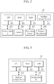
- FIG. 3 is a diagram exemplifying a hardware configuration of a remote control device 10.
- the remote control device 10 is a computer device including a CPU 101, a ROM 102, a RAM 103, an auxiliary storage device 104, and a communication IF 105.
- the CPU 101 is a processor that performs various operations.
- the RAM 102 is a volatile memory that functions as a work area when the CPU 101 executes a program.
- the ROM 103 is a non-volatile memory that stores, for example, a program and data used for starting the remote control device 10.
- the auxiliary storage device 104 is, for example, a non-volatile storage device such as an HDD or an SSD and stores a program and data used in the remote control device 10.
- the CPU 101 executes the program thereby implementing functions shown in FIG. 6 to be described below.
- the communication IF 105 is an interface that performs communication via a network 90 in accordance with a predetermined communication standard.
- FIG. 4 is a diagram exemplifying information stored in an auxiliary storage device 104 of a remote control device 10.
- the auxiliary storage device 104 stores a date and time when an image (here, a moving image) is captured by a moving image-capturing device 10, position data indicating a position at which the image is captured, image data indicating the captured image, and a result of analyzing the captured image, a processing target position data indicating a position of an area in which a process is required as the analyzing result, an analysis result of analyzing the captured image by an image recognition technology, and a content of the required process in association with each other.
- an image here, a moving image
- position data indicating a position at which the image is captured
- a processing target position data indicating a position of an area in which a process is required as the analyzing result
- an analysis result of analyzing the captured image by an image recognition technology and a content of the required process in association with each other.
- FIG. 5 is a diagram exemplifying a condition process table stored in an auxiliary storage device 104 of a remote control device 10.
- a condition of an analysis result which is set in advance and is obtained by analyzing the captured image is associated with a process required at a position matching the condition.
- a process such as agrochemical spraying is performed when the shape, color, size or the like of an object (an image object of a plant) included in an image matches the condition of the pest occurrence symptom.
- FIG. 6 is a diagram exemplifying a functional configuration of a remote control system 1.
- the remote control system 1 includes a movement unit 21, an image-capturing unit 22, a position detection unit 23, a transmission unit 24, a movement control unit 11, an acquisition unit 12, a storage unit 13, a determination unit 14, an instruction unit 15, a history storage unit 16, and a processing unit 31.
- the movement unit 21, the image-capturing unit 22, the position detection unit 23, and the transmission unit 24 are mounted on a moving image-capturing device 20.
- the movement control unit 11, the acquisition unit 12, the storage unit 13, the determination unit 14, the instruction unit 15, and the history storage unit 16 are mounted on a remote control device 10, and the processing unit 31 is mounted on a control target device 30.
- the movement unit 21 is realized by a rotation mechanism 208 of the moving image-capturing device 20, and the image-capturing unit 22 is realized by a camera 206 of the moving image-capturing device 20.
- the position detection unit 23 is realized by a positioning device 207 of the moving image-capturing device 20, and the transmission unit 24 is realized by a communication IF 205 of the moving image-capturing device 20.
- the movement control unit 11 is realized by a CPU 101 and a communication IF 105 of the remote control device 10, and the acquisition unit 12 is realized by the communication IF 105 of the remote control device 10.
- the storage unit 13 is realized by an auxiliary storage device 104 of the remote control device 10, and the determination unit 14 is realized by the CPU 101 and the auxiliary storage device 104 of the remote control device 10.
- the instruction unit 15 is realized by the communication IF 105 of the remote control device 10, and the history storage unit 16 is realized by the auxiliary storage device 104 of the remote control device 10.
- the movement control unit 11 provides the movement unit 21 with a movement instruction including a movement route, a movement speed, an altitude at moving, and start and end times of image-capturing, in order to control the movement of the moving image-capturing device 20.
- the movement unit 21 moves the moving image-capturing device 20 in accordance with the movement instruction of the movement control unit 11.
- the image-capturing unit 25 captures a moving image over a period from the start time to the end time of image-capturing along with the movement of the moving image-capturing device 20.
- the position detection unit 23 detects a position of the moving image-capturing device 20, that is, a position of the image to be captured.
- the transmission unit 24 transmits, to the remote control device 10, image data indicating the image captured by the image-capturing unit 22 and position data indicating the position of the image.
- the acquisition unit 12 acquires the image data and the position data transmitted from the transmission unit 24.
- the storage unit 13 stores the above-described condition process table, that is, information in which a condition related to an analysis result of the image data and a process to be performed by the control target device 30 are associated.
- the determination unit 14 analyzes the image data acquired by the acquisition unit 12, and determines whether the analysis result matches the condition stored in the storage unit 13.
- the instruction unit 15 specifies an area to be processed based on the position data acquired by the acquisition unit 12, and instructs the control target device 30 to perform the process associated with the condition in the area.
- the history storage unit 16 stores, as a process history, the process instructed by the instruction unit 15 and the position of the area in which the process is performed.
- the processing unit 31 performs the process in accordance with the instruction from the instruction unit 15.
- FIG. 7 is a sequence chart exemplifying an operation of a remote control system 1.
- a movement control unit 11 of a remote control device 10 provides a movement unit 21 with a movement instruction including a movement route, a movement speed, an altitude at moving, and start and end times of image-capturing via a network 90 (step S11).
- the movement instruction is prepared in advance by an administrator of the remote control system 1 or the like, and is input to the remote control device 10.
- the movement unit 21 of a moving image-capturing device 20 drives a rotation mechanism 208 to move the moving image-capturing device 20 in accordance with the movement instruction of the movement control unit 11.
- An image-capturing unit 25 captures a moving image over a period from the start time to the end time of image-capturing included in the movement instruction as the moving image-capturing device 20 moves.
- a position detection unit 23 periodically (for example, every 10 seconds) detects a position of the moving image-capturing device 20, that is, a position of an image to be captured.
- a transmission unit 24 transmits, to the remote control device 10 via the network 90, image data indicating the image captured by the image-capturing unit 22 and position data indicating the position detected by the position detection unit 23. This transmission processing may be performed after the moving image-capturing device 20 lands on a base facility provided at the flight end point, or may be performed during the flight of the moving image-capturing device 20.
- An acquisition unit 12 of the remote control device 10 acquires the image data and the position data transmitted from the transmission unit 24.
- a determination unit 14 analyzes the image data acquired by the acquisition unit 12. Specifically, the determination unit 14 analyzes the shape, color, size or the like of an object included in each image indicated by the image data by an image recognition technology, and determines whether the analysis result matches any of conditions (pest occurrence symptom, water deficiency symptom, fertilizer deficiency symptom, growth completion symptom, and the like) stored in a storage unit 13.
- an instruction unit 15 of the remote control device 10 specifies a position of an area, which is a processing target, based on the position data corresponding to the image. Specifically, the instruction unit 15 sets, as the processing target, an area having a predetermined radius centering on the position data which corresponds to the image whose analysis result matches the condition (pest occurrence symptom, water deficiency symptom, fertilizer deficiency symptom, growth completion symptom, or the like) stored in the storage unit 13.
- the instruction unit 15 then reads a process (any of agrochemical spraying, watering, additional fertilization, harvesting, and the like) associated with the above condition from the condition process table, and transmits a processing instruction including the processing target position data and its process to the control target device 30 via the network 90.
- the history storage unit 16 stores, as the process history, the process instructed by the instruction unit 15 and the processing target position data of the area where the process is performed.
- the processing unit 31 of the control target device 30 receives the processing instruction from the instruction unit 15. Then, the control target device 30 performs the process included in the processing instruction in the area indicated by the processing target position data included in the processing instruction. Specifically, in a case where the control target device 30 is capable of performing the whole process automatically, the control target device 30 moves to the area indicated by the processing target position data and performs the process. Further, in a case where a human assists or executes at least a part of the process, for example, the human refers to the processing instruction in the control target device 30, moves to the area indicated by the processing target position data, and operates the control target device 30 in the area to perform the process.
- the present invention is not limited to the above-described embodiments, and various modified examples are possible. Several modified examples are described below. Two or more of the following modified example may be combined for use.
- the present invention is applicable to a process of an animal or plant such as laver, fish, shellfish, or the like, which is cultivated in the ocean or river, or a process of an animal such as livestock kept in a ranch, in addition to the plant cultivated in the field.
- the movement control unit 11 may control the movement of the moving image-capturing device 20 depending on a type of an animal or plant included in the area to be processed. For example, when it is impossible to analyze the image unless the moving image-capturing device 20 flies at a low altitude depending on the type of animal or plant, the movement control unit 11 controls the movement of the moving image-capturing device 20 to fly at a relatively low altitude.
- the movement control unit 11 controls the movement of the moving image-capturing device 20 so that the moving image-capturing device 20 flies along a movement route in which the movement route per unit area of the moving image-capturing device 20 is made dense. Further, for example, when it is impossible to analyze the image unless the moving speed of the moving image-capturing device 20 is decreased depending on the type of animal or plant, the movement control unit 11 controls the movement of the moving image-capturing device 20 to fly at a relatively low speed.
- the determination unit 14 analyzes the image to select a necessary process in an embodiment.
- a system administrator may first designate a process, and then the determination unit 14 may determine whether or not to perform the designated process by analyzing the image.
- the movement control unit 11 may control the movement of the moving image-capturing device 20 in accordance with the designated process. For example, in a case where a process of watering is designated, it is sufficient to analyze the image even if the moving image-capturing device 20 moves quickly at a relatively high altitude since the movement route per unit area is sparse. Accordingly, the movement control unit 11 controls the moving image-capturing device 20 to perform such a movement.
- the movement control unit 11 controls the moving image-capturing device 20 to perform such a movement.
- the control target device 30 and the moving image-capturing device 20 may be the same. That is, the moving image-capturing device 20 may be used as the control target device 30.
- the transmission unit 24 of the moving image-capturing device 20 may transmit the image data indicating the image captured by the image-capturing unit 22 and the position data indicating the position detected by the position detection unit 23 during the flight of the moving image-capturing device 20.
- the determination unit 14 immediately analyzes the image data acquired by the acquisition unit 12 and determines whether the analysis result matches the condition stored in the storage unit 13. Then, when the analysis result of the determination unit 14 matches the condition stored in the storage unit 13, the instruction unit 15 instructs the control target device 30 to perform the process associated with the above condition. This processing is performed in real time while the moving image-capturing device 20 is flying.
- the area to be processed may be an area that does not include the position at which the image is captured, and may be an area that has a predetermined positional relationship with the position at which the image is captured. For example, when laver is cultivated in the ocean, a sign of occurrence of a red tide or the like may appear on the open sea side of the laver aquaculture area. Therefore, when the moving image-capturing device 20 captures the open sea side of the laver aquaculture area, and moves the facility or sprays an appropriate pesticide for an area where the laver aquaculture facility is located.
- the area to be processed is an area that does not include the position at which the image is captured, and corresponds to an area having a predetermined positional relationship with the position at which the image is captured.
- the instruction unit 15 determines a process to be instructed to the control target device 30 based on the process history stored by the history storage unit 16. For example, in a case where the agrochemical is again sprayed to an area where the process history indicating that the agrochemical has been sprayed in the past is stored, it is conceivable an example that the instruction unit 15 instructs a process of making an amount of the agrochemical less than the previous time.
- the instruction unit 15 may determine a process to be instructed to the control target device 30 based on information (for example, temperature, humidity, or precipitation amount) regarding the natural environment at the position of the image before the time when the moving image-capturing device 20 captures the image. For example, when the precipitation amount is extremely small before the time when the moving image-capturing device 20 captures the image, it is conceivable an example that the instructing unit 15 instructs the process of making the amount of watering in the area to be processed more than the usual time.
- information for example, temperature, humidity, or precipitation amount
- the image-capturing device in the present invention is not limited to the moving image-capturing device 20 such as the rotary-wing aircraft exemplified in an embodiment, but may be a device mounted on a vehicle moving on the ground, or may be a device carried by the user, such as a smartphone or a digital camera. Furthermore, the image-capturing device in the present invention does not have to be a movable device, and may be, for example, a fixed device having a camera which faces a known orientation.
- the storage unit 13 may be provided by an external computer device different from the remote control system 1.
- the function assignment between the remote control device 10 and the moving image-capturing device 20 is not limited to one exemplified in FIG. 6 .
- some of the functions implemented in the remote control device 10 may be implemented in the moving device 20.
- some or all of the functions of the determination unit 14 may be implemented in the moving image-capturing device 20.
- a computer device group that physically consists of a plurality of devices may function as the remote control device 10 in the remote control system 1.
- the programs executed by the CPU 101, the CPU 201, and the like may be provided by a storage medium such as an optical disc, a magnetic disc, or a semiconductor memory, or may be downloaded via a communication line such as the Internet. In addition, the programs may not execute all the steps described in an embodiment.
Landscapes
- Engineering & Computer Science (AREA)
- Computer Networks & Wireless Communication (AREA)
- Physics & Mathematics (AREA)
- General Physics & Mathematics (AREA)
- Control Of Position, Course, Altitude, Or Attitude Of Moving Bodies (AREA)
- Aviation & Aerospace Engineering (AREA)
- Mechanical Engineering (AREA)
- Selective Calling Equipment (AREA)
- Image Processing (AREA)
Abstract
Description
- The present invention relates to a remote control system, a remote control method and a program.
- Various techniques have been developed to support human work. For example, as a technique for supporting agricultural work, Patent Document 1 a system that includes a plurality of agricultural machines 2 which are movable and perform agricultural work, a data collecting device 3 which collects agricultural work data in each agricultural machine 2 and transmits the data to the outside, and a plurality of movable portable terminals 4 which receive the agricultural work data transmitted from the collecting device 3 and transmit the data to the server 5. The agricultural work data accumulated in the server 5 is used by an agricultural worker to create a management plan by creating a daily work report, making a work plan, or graphing the agricultural work result of each field.
- Patent Document 1: Japanese Patent Application Publication No.
2014-194601 - For example, in the technology described in Patent Document 1, it is entrusted to the agricultural worker to determine what kind of agricultural work to be performed and when. On the other hand, an object of the present invention is to make it possible to determine whether or not to perform various processes, for example, such as agricultural work without entrusting it to humans.
- The present invention provides a remote control system including an acquisition unit that acquires image data indicating an image captured by an image-capturing device and position data indicating a position of the image, a storage unit that stores a condition regarding an analysis result of the image data and a process to be performed by a control target device in association with each other, a determination unit that analyzes the acquired image data and determines whether the analysis result matches the stored condition, and an instruction unit that, when the analysis result matches the stored condition, instructs the control target device to perform the process associated with the condition in an area based on the acquired position data.
- The image-capturing device may be a moving device that is movable.
- The remote control system may further include a movement control unit that controls movement of the image-capturing device.
- The movement control unit may control the movement of the image-capturing device in accordance with a type of an animal or plant included in the area where the process is performed.
- The movement control unit may control the movement of the image-capturing device in accordance with the process, and the analysis unit may determine whether the analysis result matches the condition that is stored in association with the process.
- The control target device may be the moving device.
- The area based on the acquired position data may be an area that does not include the position indicated by the position data, and may be an area having a predetermined positional relationship with the position indicated by the position data.
- The remote control system may further include a history storage unit that stores, as a process history, the instructed process and the area where the process has been performed, and the instruction unit may determine a process to be instructed to the control target device based on the stored processing history.
- The instruction unit may determine a process to be instructed to the control target device based on information related to a natural environment at the position of the image before a time when the image is captured.
- Further, the present invention provides a remote control method including acquiring image data indicating an image captured by an image-capturing device and position data indicating a position of the image, in a storage unit that stores a condition regarding an analysis result of the image data and a process to be performed by a control target device in association with each other, determining whether an analysis result of the acquired image data matches the stored condition, and when the analysis result matches the stored condition, instructing the control target device to perform the process associated with the condition in an area based on the acquired position data.
- Furthermore, the present invention provides a program for causing one or more computers to execute acquiring image data indicating an image captured by an image-capturing device and position data indicating a position of the image, in a storage unit that stores a condition regarding an analysis result of the image data and a process to be performed by a control target device in association with each other, determining whether an analysis result of the acquired image data matches the stored condition, and when the analysis result matches the stored condition, instructing the control target device to perform the process associated with the condition in an area based on the acquired position data.
- According to the present invention, it is possible to determine whether or not to perform a process without entrusting it to humans.
-
-
FIG. 1 is a diagram exemplifying an overview of a remote control system 1 according to an embodiment of the present invention. -
FIG. 2 is a diagram exemplifying a hardware configuration of a moving image-capturingdevice 20. -
FIG. 3 is a diagram exemplifying a hardware configuration of aremote control device 10. -
FIG. 4 is a diagram exemplifying information stored in anauxiliary storage device 104 of aremote control device 10. -
FIG. 5 is a diagram exemplifying a condition process table stored in anauxiliary storage device 104 of aremote control device 10. -
FIG. 6 is a diagram exemplifying a functional configuration of a remote control system 1. -
FIG. 7 is a sequence chart exemplifying an operation of a remote control system 1. - 1: remote control system, 10: remote control device, 11: movement control unit, 12: acquisition unit, 13: storage unit, 14: determination unit, 15: instruction unit, 16: history storage unit, 20: moving image-capturing device, 21: movement unit, 22: image-capturing unit, 23: transmission unit, 24: position detection unit, 30: control target device, 31: processing unit, 90: network, 101: CPU, 102: RAM, 103: ROM, 104: auxiliary storage device, 105: communication IF, 201: CPU, 202: RAM, 203: ROM, 204: auxiliary storage device, 205: communication IF, 206: camera, 207: sensor, 2081: rotation mechanism.
-
FIG. 1 is a diagram exemplifying an overview of a remote control system 1 according to an embodiment of the present invention. The remote control system 1 includes aremote control device 10, a moving image-capturingdevice 20, acontrol target device 30, and anetwork 90 communicably connecting thesedevices 10 to 30. Thenetwork 90 is, for example, a LAN (Local Area Network), a WAN (Wide Area Network), or a combination thereof, and may include a wired section or a wireless section. Thecontrol target device 30 is, for example, an agricultural machine for performing various processes such as watering, additional fertilization, agrochemical spreading, and harvesting on a plant grown in a field. The moving image-capturingdevice 30 is a device that is movable and has an image-capturing function, and is a rotary-wing aircraft called a drone or a multicopter in the present embodiment. The moving image-capturingdevice 30 flies above the field according to an instruction of theremote control device 10, and captures an image of a plant cultivated in the field. Theremote control device 10 analyzes the image captured by the moving image-capturingdevice 30, determines what process should be performed on the plant according to the analysis result, and instructs thecontrol target device 30 to perform the determined process. Thecontrol target device 30 performs the instructed process automatically or in accordance with an operation of an agricultural worker. -
FIG. 2 is a diagram exemplifying a hardware configuration of a moving image-capturingdevice 20. The moving image-capturing device 20 includes a CPU 201 (Central Processing Unit), a ROM (Read Only Memory) 202, a RAM (Random Access Memory) 203, anauxiliary storage device 204, acommunication IF 205, acamera 206, asensor 207, and arotation mechanism 208. TheCPU 201 is a processor that performs various operations. TheRAM 202 is a volatile memory that functions as a work area when theCPU 201 executes a program. TheROM 203 is, for example, a non-volatile memory that stores a program and data used for starting the moving image-capturingdevice 20. Theauxiliary storage device 204 is, for example, a non-volatile storage device such as a hard disk drive (HDD) or a solid state drive (SSD) and stores a program and data used in the moving image-capturing device 20. TheCPU 201 executes the program so that the moving image-capturingdevice 20 functions as a computer device and functions shown inFIG. 6 to be described below are implemented. The communication IF 205 is an interface that performs communication via thenetwork 90 in accordance with a predetermined communication standard. The communication standard may be a wireless communication standard or a wired communication standard. Thecamera 206 captures an image of, for example, a space vertically below the moving image-capturingdevice 20, and generates image data indicating the captured image. Thepositioning device 207 is, for example, a GPS (Global Positioning System) unit, and detects a position of the moving image-capturingdevice 20. Therotation mechanism 208 is means for generating buoyancy in the moving image-capturingdevice 20, and includes a propeller, a shaft, a motor, and other driving mechanisms. -
FIG. 3 is a diagram exemplifying a hardware configuration of aremote control device 10. Theremote control device 10 is a computer device including aCPU 101, aROM 102, aRAM 103, anauxiliary storage device 104, and acommunication IF 105. TheCPU 101 is a processor that performs various operations. TheRAM 102 is a volatile memory that functions as a work area when theCPU 101 executes a program. TheROM 103 is a non-volatile memory that stores, for example, a program and data used for starting theremote control device 10. Theauxiliary storage device 104 is, for example, a non-volatile storage device such as an HDD or an SSD and stores a program and data used in theremote control device 10. TheCPU 101 executes the program thereby implementing functions shown inFIG. 6 to be described below. The communication IF 105 is an interface that performs communication via anetwork 90 in accordance with a predetermined communication standard. -
FIG. 4 is a diagram exemplifying information stored in anauxiliary storage device 104 of aremote control device 10. Theauxiliary storage device 104 stores a date and time when an image (here, a moving image) is captured by a moving image-capturingdevice 10, position data indicating a position at which the image is captured, image data indicating the captured image, and a result of analyzing the captured image, a processing target position data indicating a position of an area in which a process is required as the analyzing result, an analysis result of analyzing the captured image by an image recognition technology, and a content of the required process in association with each other. -
FIG. 5 is a diagram exemplifying a condition process table stored in anauxiliary storage device 104 of aremote control device 10. In the condition process table, a condition of an analysis result which is set in advance and is obtained by analyzing the captured image is associated with a process required at a position matching the condition. For example, it is defined in the condition process table that a process such as agrochemical spraying is performed when the shape, color, size or the like of an object (an image object of a plant) included in an image matches the condition of the pest occurrence symptom. -
FIG. 6 is a diagram exemplifying a functional configuration of a remote control system 1. The remote control system 1 includes amovement unit 21, an image-capturingunit 22, aposition detection unit 23, atransmission unit 24, amovement control unit 11, anacquisition unit 12, astorage unit 13, adetermination unit 14, aninstruction unit 15, ahistory storage unit 16, and aprocessing unit 31. In this example, themovement unit 21, the image-capturingunit 22, theposition detection unit 23, and thetransmission unit 24 are mounted on a moving image-capturingdevice 20. Themovement control unit 11, theacquisition unit 12, thestorage unit 13, thedetermination unit 14, theinstruction unit 15, and thehistory storage unit 16 are mounted on aremote control device 10, and theprocessing unit 31 is mounted on acontrol target device 30. - The
movement unit 21 is realized by arotation mechanism 208 of the moving image-capturingdevice 20, and the image-capturingunit 22 is realized by acamera 206 of the moving image-capturingdevice 20. Theposition detection unit 23 is realized by apositioning device 207 of the moving image-capturingdevice 20, and thetransmission unit 24 is realized by a communication IF 205 of the moving image-capturingdevice 20. Themovement control unit 11 is realized by aCPU 101 and a communication IF 105 of theremote control device 10, and theacquisition unit 12 is realized by the communication IF 105 of theremote control device 10. Thestorage unit 13 is realized by anauxiliary storage device 104 of theremote control device 10, and thedetermination unit 14 is realized by theCPU 101 and theauxiliary storage device 104 of theremote control device 10. Theinstruction unit 15 is realized by the communication IF 105 of theremote control device 10, and thehistory storage unit 16 is realized by theauxiliary storage device 104 of theremote control device 10. - The
movement control unit 11 provides themovement unit 21 with a movement instruction including a movement route, a movement speed, an altitude at moving, and start and end times of image-capturing, in order to control the movement of the moving image-capturingdevice 20. Themovement unit 21 moves the moving image-capturingdevice 20 in accordance with the movement instruction of themovement control unit 11. The image-capturing unit 25 captures a moving image over a period from the start time to the end time of image-capturing along with the movement of the moving image-capturingdevice 20. Theposition detection unit 23 detects a position of the moving image-capturingdevice 20, that is, a position of the image to be captured. Thetransmission unit 24 transmits, to theremote control device 10, image data indicating the image captured by the image-capturingunit 22 and position data indicating the position of the image. - The
acquisition unit 12 acquires the image data and the position data transmitted from thetransmission unit 24. Thestorage unit 13 stores the above-described condition process table, that is, information in which a condition related to an analysis result of the image data and a process to be performed by thecontrol target device 30 are associated. Thedetermination unit 14 analyzes the image data acquired by theacquisition unit 12, and determines whether the analysis result matches the condition stored in thestorage unit 13. When the analysis result of thedetermination unit 14 matches the condition stored in thestorage unit 13, theinstruction unit 15 specifies an area to be processed based on the position data acquired by theacquisition unit 12, and instructs thecontrol target device 30 to perform the process associated with the condition in the area. Thehistory storage unit 16 stores, as a process history, the process instructed by theinstruction unit 15 and the position of the area in which the process is performed. Theprocessing unit 31 performs the process in accordance with the instruction from theinstruction unit 15. -
FIG. 7 is a sequence chart exemplifying an operation of a remote control system 1. InFIG. 7 , amovement control unit 11 of aremote control device 10 provides amovement unit 21 with a movement instruction including a movement route, a movement speed, an altitude at moving, and start and end times of image-capturing via a network 90 (step S11). The movement instruction is prepared in advance by an administrator of the remote control system 1 or the like, and is input to theremote control device 10. - The
movement unit 21 of a moving image-capturingdevice 20 drives arotation mechanism 208 to move the moving image-capturingdevice 20 in accordance with the movement instruction of themovement control unit 11. An image-capturing unit 25 captures a moving image over a period from the start time to the end time of image-capturing included in the movement instruction as the moving image-capturingdevice 20 moves. Aposition detection unit 23 periodically (for example, every 10 seconds) detects a position of the moving image-capturingdevice 20, that is, a position of an image to be captured. Atransmission unit 24 transmits, to theremote control device 10 via thenetwork 90, image data indicating the image captured by the image-capturingunit 22 and position data indicating the position detected by theposition detection unit 23. This transmission processing may be performed after the moving image-capturingdevice 20 lands on a base facility provided at the flight end point, or may be performed during the flight of the moving image-capturingdevice 20. - An
acquisition unit 12 of theremote control device 10 acquires the image data and the position data transmitted from thetransmission unit 24. Adetermination unit 14 analyzes the image data acquired by theacquisition unit 12. Specifically, thedetermination unit 14 analyzes the shape, color, size or the like of an object included in each image indicated by the image data by an image recognition technology, and determines whether the analysis result matches any of conditions (pest occurrence symptom, water deficiency symptom, fertilizer deficiency symptom, growth completion symptom, and the like) stored in astorage unit 13. - If there is an image whose analysis result matches the condition stored in the
storage unit 13, aninstruction unit 15 of theremote control device 10 specifies a position of an area, which is a processing target, based on the position data corresponding to the image. Specifically, theinstruction unit 15 sets, as the processing target, an area having a predetermined radius centering on the position data which corresponds to the image whose analysis result matches the condition (pest occurrence symptom, water deficiency symptom, fertilizer deficiency symptom, growth completion symptom, or the like) stored in thestorage unit 13. Theinstruction unit 15 then reads a process (any of agrochemical spraying, watering, additional fertilization, harvesting, and the like) associated with the above condition from the condition process table, and transmits a processing instruction including the processing target position data and its process to thecontrol target device 30 via thenetwork 90. Thehistory storage unit 16 stores, as the process history, the process instructed by theinstruction unit 15 and the processing target position data of the area where the process is performed. - The
processing unit 31 of thecontrol target device 30 receives the processing instruction from theinstruction unit 15. Then, thecontrol target device 30 performs the process included in the processing instruction in the area indicated by the processing target position data included in the processing instruction. Specifically, in a case where thecontrol target device 30 is capable of performing the whole process automatically, thecontrol target device 30 moves to the area indicated by the processing target position data and performs the process. Further, in a case where a human assists or executes at least a part of the process, for example, the human refers to the processing instruction in thecontrol target device 30, moves to the area indicated by the processing target position data, and operates thecontrol target device 30 in the area to perform the process. - According to the present embodiment, it is possible to determine whether or not to perform various processes such as agricultural work without entrusting the determination to the human.
- The present invention is not limited to the above-described embodiments, and various modified examples are possible. Several modified examples are described below. Two or more of the following modified example may be combined for use.
- The present invention is applicable to a process of an animal or plant such as laver, fish, shellfish, or the like, which is cultivated in the ocean or river, or a process of an animal such as livestock kept in a ranch, in addition to the plant cultivated in the field.
- The
movement control unit 11 may control the movement of the moving image-capturingdevice 20 depending on a type of an animal or plant included in the area to be processed. For example, when it is impossible to analyze the image unless the moving image-capturingdevice 20 flies at a low altitude depending on the type of animal or plant, themovement control unit 11 controls the movement of the moving image-capturingdevice 20 to fly at a relatively low altitude. In addition, for example, when it is impossible to analyze the image unless the movement route per unit area of the moving image-capturingdevice 20 is dense depending on the type of animal or plant, themovement control unit 11 controls the movement of the moving image-capturingdevice 20 so that the moving image-capturingdevice 20 flies along a movement route in which the movement route per unit area of the moving image-capturingdevice 20 is made dense. Further, for example, when it is impossible to analyze the image unless the moving speed of the moving image-capturingdevice 20 is decreased depending on the type of animal or plant, themovement control unit 11 controls the movement of the moving image-capturingdevice 20 to fly at a relatively low speed. - Furthermore, in an embodiment, the
determination unit 14 analyzes the image to select a necessary process in an embodiment. Instead, for example, a system administrator may first designate a process, and then thedetermination unit 14 may determine whether or not to perform the designated process by analyzing the image. In this case, themovement control unit 11 may control the movement of the moving image-capturingdevice 20 in accordance with the designated process. For example, in a case where a process of watering is designated, it is sufficient to analyze the image even if the moving image-capturingdevice 20 moves quickly at a relatively high altitude since the movement route per unit area is sparse. Accordingly, themovement control unit 11 controls the moving image-capturingdevice 20 to perform such a movement. On the other hand, for example, in a case where a process of agrochemical spraying is designated, the sufficient image analysis cannot be performed unless the moving image-capturingdevice 20 moves slowly at a relatively low altitude since the moving route per unit area is dense. Accordingly, themovement control unit 11 controls the moving image-capturingdevice 20 to perform such a movement. - The
control target device 30 and the moving image-capturingdevice 20 may be the same. That is, the moving image-capturingdevice 20 may be used as thecontrol target device 30. In this case, thetransmission unit 24 of the moving image-capturingdevice 20 may transmit the image data indicating the image captured by the image-capturingunit 22 and the position data indicating the position detected by theposition detection unit 23 during the flight of the moving image-capturingdevice 20. In response to this, thedetermination unit 14 immediately analyzes the image data acquired by theacquisition unit 12 and determines whether the analysis result matches the condition stored in thestorage unit 13. Then, when the analysis result of thedetermination unit 14 matches the condition stored in thestorage unit 13, theinstruction unit 15 instructs thecontrol target device 30 to perform the process associated with the above condition. This processing is performed in real time while the moving image-capturingdevice 20 is flying. - The area to be processed may be an area that does not include the position at which the image is captured, and may be an area that has a predetermined positional relationship with the position at which the image is captured. For example, when laver is cultivated in the ocean, a sign of occurrence of a red tide or the like may appear on the open sea side of the laver aquaculture area. Therefore, when the moving image-capturing
device 20 captures the open sea side of the laver aquaculture area, and moves the facility or sprays an appropriate pesticide for an area where the laver aquaculture facility is located. In this case, the area to be processed is an area that does not include the position at which the image is captured, and corresponds to an area having a predetermined positional relationship with the position at which the image is captured. - The
instruction unit 15 determines a process to be instructed to thecontrol target device 30 based on the process history stored by thehistory storage unit 16. For example, in a case where the agrochemical is again sprayed to an area where the process history indicating that the agrochemical has been sprayed in the past is stored, it is conceivable an example that theinstruction unit 15 instructs a process of making an amount of the agrochemical less than the previous time. - The
instruction unit 15 may determine a process to be instructed to thecontrol target device 30 based on information (for example, temperature, humidity, or precipitation amount) regarding the natural environment at the position of the image before the time when the moving image-capturingdevice 20 captures the image. For example, when the precipitation amount is extremely small before the time when the moving image-capturingdevice 20 captures the image, it is conceivable an example that the instructingunit 15 instructs the process of making the amount of watering in the area to be processed more than the usual time. - The image-capturing device in the present invention is not limited to the moving image-capturing
device 20 such as the rotary-wing aircraft exemplified in an embodiment, but may be a device mounted on a vehicle moving on the ground, or may be a device carried by the user, such as a smartphone or a digital camera. Furthermore, the image-capturing device in the present invention does not have to be a movable device, and may be, for example, a fixed device having a camera which faces a known orientation. - A part of the functional configuration exemplified in
FIG. 6 may be omitted. For example, thestorage unit 13 may be provided by an external computer device different from the remote control system 1. Further, the function assignment between theremote control device 10 and the moving image-capturingdevice 20 is not limited to one exemplified inFIG. 6 . In an embodiment, some of the functions implemented in theremote control device 10 may be implemented in the movingdevice 20. For example, some or all of the functions of thedetermination unit 14 may be implemented in the moving image-capturingdevice 20. In addition, a computer device group that physically consists of a plurality of devices may function as theremote control device 10 in the remote control system 1. - The programs executed by the
CPU 101, theCPU 201, and the like may be provided by a storage medium such as an optical disc, a magnetic disc, or a semiconductor memory, or may be downloaded via a communication line such as the Internet. In addition, the programs may not execute all the steps described in an embodiment.
Claims (11)
- A remote control system comprising:an acquisition unit that acquires image data indicating an image captured by an image-capturing device and position data indicating a position of the image;a storage unit that stores a condition regarding an analysis result of the image data and a process to be performed by a control target device in association with each other;a determination unit that analyzes the acquired image data and determines whether the analysis result matches the stored condition; andan instruction unit that, when the analysis result matches the stored condition, instructs the control target device to perform the process associated with the condition in an area based on the acquired position data.
- The remote control system according to claim 1, wherein the image-capturing device is a moving device that is movable.
- The remote control system according to claim 2, further comprising a movement control unit that controls movement of the image-capturing device.
- The remote control system according to claim 3, wherein the movement control unit controls the movement of the image-capturing device in accordance with a type of an animal or plant included in the area where the process is performed.
- The remote control system according to claim 3, wherein the movement control unit controls the movement of the image-capturing device in accordance with the process, and
wherein the analysis unit determines whether the analysis result matches the condition that is stored in association with the process. - The remote control system according to any one of claims 2 to 5, wherein the control target device is the moving device.
- The remote control system according to any one of claims 1 to 6, wherein the area based on the acquired position data is an area that does not include the position indicated by the position data, and is an area having a predetermined positional relationship with the position indicated by the position data.
- The remote control system according to any one of claims 1 to 7, further comprising a history storage unit that stores, as a process history, the instructed process and the area where the process has been performed,
wherein the instruction unit determines a process to be instructed to the control target device based on the stored processing history. - The remote control system according to any one of claims 1 to 8, wherein the instruction unit determines a process to be instructed to the control target device based on information related to a natural environment at the position of the image before a time when the image is captured.
- A remote control method comprising:acquiring image data indicating an image captured by an image-capturing device and position data indicating a position of the image;in a storage unit that stores a condition regarding an analysis result of the image data and a process to be performed by a control target device in association with each other, determining whether an analysis result of the acquired image data matches the stored condition; andwhen the analysis result matches the stored condition, instructing the control target device to perform the process associated with the condition in an area based on the acquired position data.
- A program for causing one or more computers to execute:acquiring image data indicating an image captured by an image-capturing device and position data indicating a position of the image;in a storage unit that stores a condition regarding an analysis result of the image data and a process to be performed by a control target device in association with each other, determining whether an analysis result of the acquired image data matches the stored condition; andwhen the analysis result matches the stored condition, instructing the control target device to perform the process associated with the condition in an area based on the acquired position data.
Applications Claiming Priority (1)
| Application Number | Priority Date | Filing Date | Title |
|---|---|---|---|
| PCT/JP2016/086866 WO2018109796A1 (en) | 2016-12-12 | 2016-12-12 | Remote control system, remote control method, and program |
Publications (3)
| Publication Number | Publication Date |
|---|---|
| EP3554094A1 true EP3554094A1 (en) | 2019-10-16 |
| EP3554094A4 EP3554094A4 (en) | 2020-07-29 |
| EP3554094B1 EP3554094B1 (en) | 2022-07-20 |
Family
ID=62558124
Family Applications (1)
| Application Number | Title | Priority Date | Filing Date |
|---|---|---|---|
| EP16923843.3A Active EP3554094B1 (en) | 2016-12-12 | 2016-12-12 | Remote control system, remote control method, and program |
Country Status (5)
| Country | Link |
|---|---|
| US (1) | US10913533B2 (en) |
| EP (1) | EP3554094B1 (en) |
| JP (1) | JP6621942B2 (en) |
| CN (1) | CN110063061B (en) |
| WO (1) | WO2018109796A1 (en) |
Families Citing this family (1)
| Publication number | Priority date | Publication date | Assignee | Title |
|---|---|---|---|---|
| WO2020189506A1 (en) * | 2019-03-18 | 2020-09-24 | 株式会社ナイルワークス | Drone, drone control method, and drone control program |
Family Cites Families (42)
| Publication number | Priority date | Publication date | Assignee | Title |
|---|---|---|---|---|
| US20040141641A1 (en) * | 2003-01-21 | 2004-07-22 | Mcdonald Miller Baird | Seed image analyzer |
| JPWO2005022902A1 (en) * | 2003-09-01 | 2006-11-02 | 松下電器産業株式会社 | Camera with transmission function and mobile phone, image data acquisition and transmission program |
| JP2006174415A (en) * | 2004-11-19 | 2006-06-29 | Ntt Docomo Inc | Image decoding apparatus, image decoding program, image decoding method, image encoding apparatus, image encoding program, and image encoding method |
| US7756362B2 (en) * | 2005-01-28 | 2010-07-13 | Canon Kabushiki Kaisha | Image processing apparatus, control method therefor, computer program, and computer-readable storage medium |
| JP5009577B2 (en) * | 2005-09-30 | 2012-08-22 | 富士フイルム株式会社 | Image search apparatus and method, and program |
| US8417534B2 (en) * | 2006-12-29 | 2013-04-09 | Pioneer Hi-Bred International, Inc. | Automated location-based information recall |
| US8254712B2 (en) * | 2007-03-30 | 2012-08-28 | Fujifilm Corporation | Image processing apparatus, image processing method, image managing apparatus, image managing method, computer program product, and image order sheet |
| JP5181294B2 (en) * | 2008-03-31 | 2013-04-10 | 富士フイルム株式会社 | Imaging system, imaging method, and program |
| JP5231284B2 (en) * | 2008-03-31 | 2013-07-10 | 富士フイルム株式会社 | Imaging apparatus, imaging method, and program |
| JP5111255B2 (en) * | 2008-06-20 | 2013-01-09 | キヤノン株式会社 | Image processing apparatus, image processing method, computer program, and recording medium |
| BRPI1010018A2 (en) * | 2009-05-01 | 2016-04-12 | Nokia Corp | method and apparatus for collecting data for agricultural analysis |
| PL2437586T3 (en) * | 2009-06-02 | 2019-02-28 | Topcon Precision Agriculture Pty Ltd | Vehicle guidance system |
| JP2011254711A (en) | 2010-06-05 | 2011-12-22 | Zukosha:Kk | Fertilization map generating system, method for the same, industrial helicopter, server, and controlled fertilizer applicator |
| JP5641813B2 (en) * | 2010-08-17 | 2014-12-17 | キヤノン株式会社 | Imaging apparatus and imaging method, image processing apparatus and image processing method |
| JP2013179564A (en) * | 2012-02-01 | 2013-09-09 | Canon Inc | Image processing method, image processing device, and imaging device |
| JP5597772B2 (en) | 2012-03-12 | 2014-10-01 | 株式会社Nttドコモ | Remote control system, remote control method, communication apparatus and program |
| CN102854851A (en) * | 2012-07-25 | 2013-01-02 | 深圳市深芯半导体有限公司 | Internet integrated operating system |
| JP5997039B2 (en) * | 2012-12-26 | 2016-09-21 | 株式会社日立ハイテクノロジーズ | Defect inspection method and defect inspection apparatus |
| JP6013253B2 (en) | 2013-03-28 | 2016-10-25 | 株式会社クボタ | Agricultural work data management system |
| US10083370B2 (en) * | 2013-04-04 | 2018-09-25 | Nec Corporation | Identification system, identification method, matching device, and program |
| CN203399548U (en) * | 2013-08-04 | 2014-01-22 | 天津三兴宏高科技有限公司 | Facility agriculture automation management machine |
| JP6270388B2 (en) * | 2013-09-13 | 2018-01-31 | オリンパス株式会社 | Imaging apparatus, microscope system, imaging method, and imaging program |
| JP5574556B1 (en) * | 2013-09-26 | 2014-08-20 | 株式会社電通 | Viewing program identification system, method and program |
| KR102066939B1 (en) * | 2013-09-27 | 2020-01-16 | 한화테크윈 주식회사 | Image monitoring system |
| JP5499212B1 (en) * | 2013-10-23 | 2014-05-21 | NEUSOFT Japan株式会社 | Remote operation reception system, remote operation system and program |
| CN103795974A (en) * | 2013-11-05 | 2014-05-14 | 陕西科技大学 | Mobile camera system for monitoring greenhouse plant and method |
| JP6537332B2 (en) * | 2014-04-28 | 2019-07-03 | キヤノン株式会社 | Image processing method and photographing apparatus |
| CN104007733B (en) * | 2014-06-05 | 2017-08-04 | 山东省农业科学院科技信息研究所 | It is a kind of that the system and method being monitored is produced to intensive agriculture |
| JP6300658B2 (en) * | 2014-06-19 | 2018-03-28 | オリンパス株式会社 | Sample observation equipment |
| KR101650924B1 (en) * | 2014-07-01 | 2016-08-24 | 주식회사 아이티엑스엠투엠 | System for intelligently analyzing video data and method thereof |
| WO2016009688A1 (en) * | 2014-07-16 | 2016-01-21 | 株式会社リコー | System, machine, control method, and program |
| KR102369652B1 (en) * | 2014-12-23 | 2022-03-11 | 삼성전자주식회사 | Image processing apparatus, medical image apparatus and processing method for the medical image |
| JP2016131517A (en) | 2015-01-19 | 2016-07-25 | 日本電信電話株式会社 | Operation determination apparatus, operation determination system, operation determination method, and operation determination program |
| CN104794189B (en) * | 2015-04-16 | 2018-05-08 | 惠州Tcl移动通信有限公司 | A kind of method for screening images and screening system |
| JP6521763B2 (en) * | 2015-06-26 | 2019-05-29 | キヤノン株式会社 | Image processing apparatus, imaging apparatus, image processing method, program, and recording medium |
| WO2017006314A1 (en) * | 2015-07-05 | 2017-01-12 | THE WHOLLYSEE.Ltd. | Optical identification and characterization system and tagss |
| US10484601B2 (en) * | 2015-08-31 | 2019-11-19 | Canon Kabushiki Kaisha | Image processing apparatus, image processing method, and storage medium |
| JP6314951B2 (en) * | 2015-10-08 | 2018-04-25 | コニカミノルタ株式会社 | Image forming system and program |
| JP6200483B2 (en) * | 2015-12-23 | 2017-09-20 | 株式会社オプティム | Image processing system, image processing method, and image processing program |
| US9870609B2 (en) * | 2016-06-03 | 2018-01-16 | Conduent Business Services, Llc | System and method for assessing usability of captured images |
| US11055786B2 (en) * | 2016-06-03 | 2021-07-06 | Conduent Business Services, Llc | Image segmentation system for verification of property roof damage |
| JP7121629B2 (en) * | 2018-10-25 | 2022-08-18 | 株式会社 ミックウェア | IMAGING DEVICE, PROGRAM, AND CONTENT SHARING SYSTEM |
-
2016
- 2016-12-12 JP JP2018556030A patent/JP6621942B2/en active Active
- 2016-12-12 WO PCT/JP2016/086866 patent/WO2018109796A1/en active Application Filing
- 2016-12-12 US US16/467,603 patent/US10913533B2/en active Active
- 2016-12-12 EP EP16923843.3A patent/EP3554094B1/en active Active
- 2016-12-12 CN CN201680091530.9A patent/CN110063061B/en active Active
Also Published As
| Publication number | Publication date |
|---|---|
| CN110063061B (en) | 2022-02-22 |
| WO2018109796A1 (en) | 2018-06-21 |
| US20200070975A1 (en) | 2020-03-05 |
| CN110063061A (en) | 2019-07-26 |
| EP3554094B1 (en) | 2022-07-20 |
| JP6621942B2 (en) | 2019-12-18 |
| US10913533B2 (en) | 2021-02-09 |
| JPWO2018109796A1 (en) | 2019-10-24 |
| EP3554094A4 (en) | 2020-07-29 |
Similar Documents
| Publication | Publication Date | Title |
|---|---|---|
| CA3095725C (en) | Visual observer of unmanned aerial vehicle for monitoring horticultural grow operations | |
| Lennox et al. | Envisioning the future of aquatic animal tracking: technology, science, and application | |
| US10846843B2 (en) | Utilizing artificial intelligence with captured images to detect agricultural failure | |
| Bagheri | Development of a high-resolution aerial remote-sensing system for precision agriculture | |
| US11137775B2 (en) | Unmanned aerial vehicle | |
| KR20200065696A (en) | system for monitoring agricultural produce using drone | |
| CN114206110A (en) | Method for generating an application map for processing a field with agricultural equipment | |
| WO2018048387A1 (en) | Systems and methods for mapping emerged plants | |
| EP3516580B1 (en) | Control of harmful organisms | |
| EP3679776A1 (en) | Method of collecting soil data via an uav | |
| JPWO2019082519A1 (en) | Information processing equipment, information processing methods, programs, information processing systems | |
| Park et al. | Detection of soybean insect pest and a forecasting platform using deep learning with unmanned ground vehicles | |
| US10913533B2 (en) | Remote control system, remote control method and program | |
| Christensen et al. | Sensing for weed detection | |
| Dong et al. | 4D mapping of fields using autonomous ground and aerial vehicles | |
| CN112153892B (en) | Device for fly management | |
| Padubidri et al. | The Be-Hive Project—Counting Bee Traffic Based on Deep Learning and Pose Estimation | |
| Kakarla et al. | Preflight and Flight Instructions on the Use of Unmanned Aerial Vehicles (UAVs) for Agricultural Applications: AE535, 11/2019 | |
| JP2022148500A (en) | Vermin damage estimation device and vermin damage estimation system | |
| Segaran et al. | Nesting waterbird colony population size monitoring using automated counts on drone imagery | |
| Joseph et al. | Automated Papaya Farm Monitoring system using Unmanned Aerial Vehicle (UAV) | |
| Kulhandjian et al. | Low-Cost Tree Health Categorization and Localization Using Drones and Machine Learning | |
| JP2018073175A (en) | Information processing device, control method thereof, and program | |
| Ferreira | Identification of vinegrape varieties through convolutional neural networks | |
| Bhusal | Unmanned Aerial System (UAS) for Bird Damage Control in Wine Grapes |
Legal Events
| Date | Code | Title | Description |
|---|---|---|---|
| STAA | Information on the status of an ep patent application or granted ep patent |
Free format text: STATUS: THE INTERNATIONAL PUBLICATION HAS BEEN MADE |
|
| PUAI | Public reference made under article 153(3) epc to a published international application that has entered the european phase |
Free format text: ORIGINAL CODE: 0009012 |
|
| STAA | Information on the status of an ep patent application or granted ep patent |
Free format text: STATUS: REQUEST FOR EXAMINATION WAS MADE |
|
| 17P | Request for examination filed |
Effective date: 20190701 |
|
| AK | Designated contracting states |
Kind code of ref document: A1 Designated state(s): AL AT BE BG CH CY CZ DE DK EE ES FI FR GB GR HR HU IE IS IT LI LT LU LV MC MK MT NL NO PL PT RO RS SE SI SK SM TR |
|
| AX | Request for extension of the european patent |
Extension state: BA ME |
|
| DAV | Request for validation of the european patent (deleted) | ||
| DAX | Request for extension of the european patent (deleted) | ||
| A4 | Supplementary search report drawn up and despatched |
Effective date: 20200626 |
|
| RIC1 | Information provided on ipc code assigned before grant |
Ipc: H04Q 9/00 20060101AFI20200622BHEP |
|
| GRAP | Despatch of communication of intention to grant a patent |
Free format text: ORIGINAL CODE: EPIDOSNIGR1 |
|
| STAA | Information on the status of an ep patent application or granted ep patent |
Free format text: STATUS: GRANT OF PATENT IS INTENDED |
|
| INTG | Intention to grant announced |
Effective date: 20220210 |
|
| GRAS | Grant fee paid |
Free format text: ORIGINAL CODE: EPIDOSNIGR3 |
|
| GRAA | (expected) grant |
Free format text: ORIGINAL CODE: 0009210 |
|
| STAA | Information on the status of an ep patent application or granted ep patent |
Free format text: STATUS: THE PATENT HAS BEEN GRANTED |
|
| AK | Designated contracting states |
Kind code of ref document: B1 Designated state(s): AL AT BE BG CH CY CZ DE DK EE ES FI FR GB GR HR HU IE IS IT LI LT LU LV MC MK MT NL NO PL PT RO RS SE SI SK SM TR |
|
| REG | Reference to a national code |
Ref country code: CH Ref legal event code: EP |
|
| REG | Reference to a national code |
Ref country code: DE Ref legal event code: R096 Ref document number: 602016073713 Country of ref document: DE |
|
| REG | Reference to a national code |
Ref country code: AT Ref legal event code: REF Ref document number: 1506337 Country of ref document: AT Kind code of ref document: T Effective date: 20220815 |
|
| REG | Reference to a national code |
Ref country code: IE Ref legal event code: FG4D |
|
| REG | Reference to a national code |
Ref country code: LT Ref legal event code: MG9D |
|
| REG | Reference to a national code |
Ref country code: NL Ref legal event code: MP Effective date: 20220720 |
|
| PG25 | Lapsed in a contracting state [announced via postgrant information from national office to epo] |
Ref country code: SE Free format text: LAPSE BECAUSE OF FAILURE TO SUBMIT A TRANSLATION OF THE DESCRIPTION OR TO PAY THE FEE WITHIN THE PRESCRIBED TIME-LIMIT Effective date: 20220720 Ref country code: RS Free format text: LAPSE BECAUSE OF FAILURE TO SUBMIT A TRANSLATION OF THE DESCRIPTION OR TO PAY THE FEE WITHIN THE PRESCRIBED TIME-LIMIT Effective date: 20220720 Ref country code: PT Free format text: LAPSE BECAUSE OF FAILURE TO SUBMIT A TRANSLATION OF THE DESCRIPTION OR TO PAY THE FEE WITHIN THE PRESCRIBED TIME-LIMIT Effective date: 20221121 Ref country code: NO Free format text: LAPSE BECAUSE OF FAILURE TO SUBMIT A TRANSLATION OF THE DESCRIPTION OR TO PAY THE FEE WITHIN THE PRESCRIBED TIME-LIMIT Effective date: 20221020 Ref country code: NL Free format text: LAPSE BECAUSE OF FAILURE TO SUBMIT A TRANSLATION OF THE DESCRIPTION OR TO PAY THE FEE WITHIN THE PRESCRIBED TIME-LIMIT Effective date: 20220720 Ref country code: LV Free format text: LAPSE BECAUSE OF FAILURE TO SUBMIT A TRANSLATION OF THE DESCRIPTION OR TO PAY THE FEE WITHIN THE PRESCRIBED TIME-LIMIT Effective date: 20220720 Ref country code: LT Free format text: LAPSE BECAUSE OF FAILURE TO SUBMIT A TRANSLATION OF THE DESCRIPTION OR TO PAY THE FEE WITHIN THE PRESCRIBED TIME-LIMIT Effective date: 20220720 Ref country code: FI Free format text: LAPSE BECAUSE OF FAILURE TO SUBMIT A TRANSLATION OF THE DESCRIPTION OR TO PAY THE FEE WITHIN THE PRESCRIBED TIME-LIMIT Effective date: 20220720 Ref country code: ES Free format text: LAPSE BECAUSE OF FAILURE TO SUBMIT A TRANSLATION OF THE DESCRIPTION OR TO PAY THE FEE WITHIN THE PRESCRIBED TIME-LIMIT Effective date: 20220720 |
|
| REG | Reference to a national code |
Ref country code: AT Ref legal event code: MK05 Ref document number: 1506337 Country of ref document: AT Kind code of ref document: T Effective date: 20220720 |
|
| PG25 | Lapsed in a contracting state [announced via postgrant information from national office to epo] |
Ref country code: PL Free format text: LAPSE BECAUSE OF FAILURE TO SUBMIT A TRANSLATION OF THE DESCRIPTION OR TO PAY THE FEE WITHIN THE PRESCRIBED TIME-LIMIT Effective date: 20220720 Ref country code: IS Free format text: LAPSE BECAUSE OF FAILURE TO SUBMIT A TRANSLATION OF THE DESCRIPTION OR TO PAY THE FEE WITHIN THE PRESCRIBED TIME-LIMIT Effective date: 20221120 Ref country code: HR Free format text: LAPSE BECAUSE OF FAILURE TO SUBMIT A TRANSLATION OF THE DESCRIPTION OR TO PAY THE FEE WITHIN THE PRESCRIBED TIME-LIMIT Effective date: 20220720 Ref country code: GR Free format text: LAPSE BECAUSE OF FAILURE TO SUBMIT A TRANSLATION OF THE DESCRIPTION OR TO PAY THE FEE WITHIN THE PRESCRIBED TIME-LIMIT Effective date: 20221021 |
|
| REG | Reference to a national code |
Ref country code: DE Ref legal event code: R097 Ref document number: 602016073713 Country of ref document: DE |
|
| PG25 | Lapsed in a contracting state [announced via postgrant information from national office to epo] |
Ref country code: SM Free format text: LAPSE BECAUSE OF FAILURE TO SUBMIT A TRANSLATION OF THE DESCRIPTION OR TO PAY THE FEE WITHIN THE PRESCRIBED TIME-LIMIT Effective date: 20220720 Ref country code: RO Free format text: LAPSE BECAUSE OF FAILURE TO SUBMIT A TRANSLATION OF THE DESCRIPTION OR TO PAY THE FEE WITHIN THE PRESCRIBED TIME-LIMIT Effective date: 20220720 Ref country code: DK Free format text: LAPSE BECAUSE OF FAILURE TO SUBMIT A TRANSLATION OF THE DESCRIPTION OR TO PAY THE FEE WITHIN THE PRESCRIBED TIME-LIMIT Effective date: 20220720 Ref country code: CZ Free format text: LAPSE BECAUSE OF FAILURE TO SUBMIT A TRANSLATION OF THE DESCRIPTION OR TO PAY THE FEE WITHIN THE PRESCRIBED TIME-LIMIT Effective date: 20220720 Ref country code: AT Free format text: LAPSE BECAUSE OF FAILURE TO SUBMIT A TRANSLATION OF THE DESCRIPTION OR TO PAY THE FEE WITHIN THE PRESCRIBED TIME-LIMIT Effective date: 20220720 |
|
| PLBE | No opposition filed within time limit |
Free format text: ORIGINAL CODE: 0009261 |
|
| STAA | Information on the status of an ep patent application or granted ep patent |
Free format text: STATUS: NO OPPOSITION FILED WITHIN TIME LIMIT |
|
| PG25 | Lapsed in a contracting state [announced via postgrant information from national office to epo] |
Ref country code: SK Free format text: LAPSE BECAUSE OF FAILURE TO SUBMIT A TRANSLATION OF THE DESCRIPTION OR TO PAY THE FEE WITHIN THE PRESCRIBED TIME-LIMIT Effective date: 20220720 Ref country code: EE Free format text: LAPSE BECAUSE OF FAILURE TO SUBMIT A TRANSLATION OF THE DESCRIPTION OR TO PAY THE FEE WITHIN THE PRESCRIBED TIME-LIMIT Effective date: 20220720 |
|
| 26N | No opposition filed |
Effective date: 20230421 |
|
| PG25 | Lapsed in a contracting state [announced via postgrant information from national office to epo] |
Ref country code: AL Free format text: LAPSE BECAUSE OF FAILURE TO SUBMIT A TRANSLATION OF THE DESCRIPTION OR TO PAY THE FEE WITHIN THE PRESCRIBED TIME-LIMIT Effective date: 20220720 |
|
| REG | Reference to a national code |
Ref country code: CH Ref legal event code: PL |
|
| GBPC | Gb: european patent ceased through non-payment of renewal fee |
Effective date: 20221212 |
|
| REG | Reference to a national code |
Ref country code: BE Ref legal event code: MM Effective date: 20221231 |
|
| PG25 | Lapsed in a contracting state [announced via postgrant information from national office to epo] |
Ref country code: SI Free format text: LAPSE BECAUSE OF FAILURE TO SUBMIT A TRANSLATION OF THE DESCRIPTION OR TO PAY THE FEE WITHIN THE PRESCRIBED TIME-LIMIT Effective date: 20220720 Ref country code: LU Free format text: LAPSE BECAUSE OF NON-PAYMENT OF DUE FEES Effective date: 20221212 |
|
| PG25 | Lapsed in a contracting state [announced via postgrant information from national office to epo] |
Ref country code: LI Free format text: LAPSE BECAUSE OF NON-PAYMENT OF DUE FEES Effective date: 20221231 Ref country code: IE Free format text: LAPSE BECAUSE OF NON-PAYMENT OF DUE FEES Effective date: 20221212 Ref country code: GB Free format text: LAPSE BECAUSE OF NON-PAYMENT OF DUE FEES Effective date: 20221212 Ref country code: CH Free format text: LAPSE BECAUSE OF NON-PAYMENT OF DUE FEES Effective date: 20221231 |
|
| PG25 | Lapsed in a contracting state [announced via postgrant information from national office to epo] |
Ref country code: BE Free format text: LAPSE BECAUSE OF NON-PAYMENT OF DUE FEES Effective date: 20221231 |
|
| PGFP | Annual fee paid to national office [announced via postgrant information from national office to epo] |
Ref country code: FR Payment date: 20231222 Year of fee payment: 8 Ref country code: DE Payment date: 20231214 Year of fee payment: 8 |
|
| PG25 | Lapsed in a contracting state [announced via postgrant information from national office to epo] |
Ref country code: HU Free format text: LAPSE BECAUSE OF FAILURE TO SUBMIT A TRANSLATION OF THE DESCRIPTION OR TO PAY THE FEE WITHIN THE PRESCRIBED TIME-LIMIT; INVALID AB INITIO Effective date: 20161212 |
|
| PG25 | Lapsed in a contracting state [announced via postgrant information from national office to epo] |
Ref country code: CY Free format text: LAPSE BECAUSE OF FAILURE TO SUBMIT A TRANSLATION OF THE DESCRIPTION OR TO PAY THE FEE WITHIN THE PRESCRIBED TIME-LIMIT Effective date: 20220720 |
|
| PG25 | Lapsed in a contracting state [announced via postgrant information from national office to epo] |
Ref country code: MK Free format text: LAPSE BECAUSE OF FAILURE TO SUBMIT A TRANSLATION OF THE DESCRIPTION OR TO PAY THE FEE WITHIN THE PRESCRIBED TIME-LIMIT Effective date: 20220720 Ref country code: IT Free format text: LAPSE BECAUSE OF FAILURE TO SUBMIT A TRANSLATION OF THE DESCRIPTION OR TO PAY THE FEE WITHIN THE PRESCRIBED TIME-LIMIT Effective date: 20220720 |
|
| PG25 | Lapsed in a contracting state [announced via postgrant information from national office to epo] |
Ref country code: MC Free format text: LAPSE BECAUSE OF FAILURE TO SUBMIT A TRANSLATION OF THE DESCRIPTION OR TO PAY THE FEE WITHIN THE PRESCRIBED TIME-LIMIT Effective date: 20220720 |
|
| PG25 | Lapsed in a contracting state [announced via postgrant information from national office to epo] |
Ref country code: MC Free format text: LAPSE BECAUSE OF FAILURE TO SUBMIT A TRANSLATION OF THE DESCRIPTION OR TO PAY THE FEE WITHIN THE PRESCRIBED TIME-LIMIT Effective date: 20220720 |
|
| PG25 | Lapsed in a contracting state [announced via postgrant information from national office to epo] |
Ref country code: BG Free format text: LAPSE BECAUSE OF FAILURE TO SUBMIT A TRANSLATION OF THE DESCRIPTION OR TO PAY THE FEE WITHIN THE PRESCRIBED TIME-LIMIT Effective date: 20220720 |
|
| PG25 | Lapsed in a contracting state [announced via postgrant information from national office to epo] |
Ref country code: MT Free format text: LAPSE BECAUSE OF FAILURE TO SUBMIT A TRANSLATION OF THE DESCRIPTION OR TO PAY THE FEE WITHIN THE PRESCRIBED TIME-LIMIT Effective date: 20220720 |