EP3553926B1 - Electromechanical actuator - Google Patents
Electromechanical actuator Download PDFInfo
- Publication number
- EP3553926B1 EP3553926B1 EP18167274.2A EP18167274A EP3553926B1 EP 3553926 B1 EP3553926 B1 EP 3553926B1 EP 18167274 A EP18167274 A EP 18167274A EP 3553926 B1 EP3553926 B1 EP 3553926B1
- Authority
- EP
- European Patent Office
- Prior art keywords
- rotor
- converter
- stator
- electromechanical actuator
- actuation member
- Prior art date
- Legal status (The legal status is an assumption and is not a legal conclusion. Google has not performed a legal analysis and makes no representation as to the accuracy of the status listed.)
- Active
Links
- 230000033001 locomotion Effects 0.000 claims description 12
- 238000006243 chemical reaction Methods 0.000 claims description 11
- 230000008878 coupling Effects 0.000 claims description 11
- 238000010168 coupling process Methods 0.000 claims description 11
- 238000005859 coupling reaction Methods 0.000 claims description 11
- 238000004804 winding Methods 0.000 claims description 8
- 238000005096 rolling process Methods 0.000 claims description 2
- 230000007935 neutral effect Effects 0.000 description 4
- 238000006073 displacement reaction Methods 0.000 description 2
- RYGMFSIKBFXOCR-UHFFFAOYSA-N Copper Chemical compound [Cu] RYGMFSIKBFXOCR-UHFFFAOYSA-N 0.000 description 1
- 229910000831 Steel Inorganic materials 0.000 description 1
- 206010043183 Teething Diseases 0.000 description 1
- 230000005540 biological transmission Effects 0.000 description 1
- 229910052802 copper Inorganic materials 0.000 description 1
- 239000010949 copper Substances 0.000 description 1
- 230000001419 dependent effect Effects 0.000 description 1
- 238000009434 installation Methods 0.000 description 1
- 238000003475 lamination Methods 0.000 description 1
- 230000005291 magnetic effect Effects 0.000 description 1
- 239000007787 solid Substances 0.000 description 1
- 239000010959 steel Substances 0.000 description 1
- 230000036346 tooth eruption Effects 0.000 description 1
Images


Classifications
-
- H—ELECTRICITY
- H02—GENERATION; CONVERSION OR DISTRIBUTION OF ELECTRIC POWER
- H02K—DYNAMO-ELECTRIC MACHINES
- H02K7/00—Arrangements for handling mechanical energy structurally associated with dynamo-electric machines, e.g. structural association with mechanical driving motors or auxiliary dynamo-electric machines
- H02K7/06—Means for converting reciprocating motion into rotary motion or vice versa
-
- F—MECHANICAL ENGINEERING; LIGHTING; HEATING; WEAPONS; BLASTING
- F16—ENGINEERING ELEMENTS AND UNITS; GENERAL MEASURES FOR PRODUCING AND MAINTAINING EFFECTIVE FUNCTIONING OF MACHINES OR INSTALLATIONS; THERMAL INSULATION IN GENERAL
- F16H—GEARING
- F16H61/00—Control functions within control units of change-speed- or reversing-gearings for conveying rotary motion ; Control of exclusively fluid gearing, friction gearing, gearings with endless flexible members or other particular types of gearing
- F16H61/26—Generation or transmission of movements for final actuating mechanisms
- F16H61/28—Generation or transmission of movements for final actuating mechanisms with at least one movement of the final actuating mechanism being caused by a non-mechanical force, e.g. power-assisted
- F16H61/32—Electric motors actuators or related electrical control means therefor
-
- H—ELECTRICITY
- H02—GENERATION; CONVERSION OR DISTRIBUTION OF ELECTRIC POWER
- H02K—DYNAMO-ELECTRIC MACHINES
- H02K7/00—Arrangements for handling mechanical energy structurally associated with dynamo-electric machines, e.g. structural association with mechanical driving motors or auxiliary dynamo-electric machines
- H02K7/08—Structural association with bearings
- H02K7/086—Structural association with bearings radially supporting the rotor around a fixed spindle; radially supporting the rotor directly
- H02K7/088—Structural association with bearings radially supporting the rotor around a fixed spindle; radially supporting the rotor directly radially supporting the rotor directly
-
- F—MECHANICAL ENGINEERING; LIGHTING; HEATING; WEAPONS; BLASTING
- F16—ENGINEERING ELEMENTS AND UNITS; GENERAL MEASURES FOR PRODUCING AND MAINTAINING EFFECTIVE FUNCTIONING OF MACHINES OR INSTALLATIONS; THERMAL INSULATION IN GENERAL
- F16H—GEARING
- F16H61/00—Control functions within control units of change-speed- or reversing-gearings for conveying rotary motion ; Control of exclusively fluid gearing, friction gearing, gearings with endless flexible members or other particular types of gearing
- F16H61/26—Generation or transmission of movements for final actuating mechanisms
- F16H61/28—Generation or transmission of movements for final actuating mechanisms with at least one movement of the final actuating mechanism being caused by a non-mechanical force, e.g. power-assisted
- F16H2061/2869—Cam or crank gearing
-
- F—MECHANICAL ENGINEERING; LIGHTING; HEATING; WEAPONS; BLASTING
- F16—ENGINEERING ELEMENTS AND UNITS; GENERAL MEASURES FOR PRODUCING AND MAINTAINING EFFECTIVE FUNCTIONING OF MACHINES OR INSTALLATIONS; THERMAL INSULATION IN GENERAL
- F16H—GEARING
- F16H61/00—Control functions within control units of change-speed- or reversing-gearings for conveying rotary motion ; Control of exclusively fluid gearing, friction gearing, gearings with endless flexible members or other particular types of gearing
- F16H61/26—Generation or transmission of movements for final actuating mechanisms
- F16H61/28—Generation or transmission of movements for final actuating mechanisms with at least one movement of the final actuating mechanism being caused by a non-mechanical force, e.g. power-assisted
- F16H2061/2884—Screw-nut devices
-
- H—ELECTRICITY
- H02—GENERATION; CONVERSION OR DISTRIBUTION OF ELECTRIC POWER
- H02K—DYNAMO-ELECTRIC MACHINES
- H02K2201/00—Specific aspects not provided for in the other groups of this subclass relating to the magnetic circuits
- H02K2201/03—Machines characterised by aspects of the air-gap between rotor and stator
Landscapes
- Engineering & Computer Science (AREA)
- Power Engineering (AREA)
- General Engineering & Computer Science (AREA)
- Mechanical Engineering (AREA)
- Connection Of Motors, Electrical Generators, Mechanical Devices, And The Like (AREA)
Description
- The present invention relates to an electromechanical actuator and, in particular, to a compact electromechanical actuator for motor vehicles.
- Conventional electro-pneumatic actuators are used on commercial vehicles, wherein these actuators utilize pneumatic energy sources via pneumatic cylinders to provide the actuation for different devices such as a clutch, a gear shift, a countershaft brake, wheel brake actuators. In most cases the actuation implies an axial (linear) displacement of an actuation member transmitting an actuation force to achieve a desired result.
- As hybrid and pure electric vehicles are getting more and more widespread and compressed air is getting less commonly available, there is an increasing demand for pure electromechanical actuators.
DE 10 2006 015 688 A1 discloses an actuator assembly which is driven by electric motor, wherein a rotation-translation converter is arranged between the rotor and the stator.DE 10 2012 012 656 A1 discloses another actuator assembly which is driven by electric motor, wherein rotation-translation converter is arranged between the rotor and the stator to move a shaft in a translational direction.US 5,205,179 A discloses yet another actuator assembly which is driven by an electric motor. Furthermore,US 6,886,425 B2 discloses a conventional electromagnetic shift arrangement, wherein a linear shift of an actuation member is provided by an electromagnetic device. Another conventional actuator is disclosed inUS 8,344,565 , where an actuation arrangement comprises an actuation member that is driven by an electric machine mounted axially displaceable on a rotary shaft. These conventional actuators, however, involve many different components and are thus not as reliable as desired. - Therefore, there is a need for alternative solutions for an electromechanical actuator suitable in motor vehicles.
- At least some of the problems of the conventional devices are overcome by an electromechanical actuator according to claim 1 and a vehicle according to claim 11. The dependent claims refer to specifically advantageous realizations of the subject matter of claim 1.
- The present invention relates to an electromechanical actuator for a motor vehicle. The actuator comprises an electric motor unit with a stator and a rotor, and a converter to convert a (relative) rotation between the stator and the rotor into a (relative) translation enabling an actuation in the motor vehicle, wherein at least part of the converter is arranged on a surface of the stator facing the rotor. The translation shall, in particular, include a linear or axial motion or displacement relative between the stator and the rotor, wherein the axial direction shall refer to a direction substantially parallel to a rotation axis of the relative rotation between the stator and rotor.
- Optionally, the converter comprises at least one of the following connection or coupling elements: a thread, a pin in a groove coupling, two grooves with rolling elements in-between, a pin to cam connection, another component providing a linear movement upon a relative rotation between the stator and the rotor.
- Within the present invention the term "connection" or "connecting" does not necessarily mean that the respective components are rigidly fixed to one another, but merely that there is some kind of coupling that allows to transfer a force or a momentum.
- Optionally, the electric motor unit and the converter form one integrated unit. Hence, the converter may be formed directly as part of at least one component of the electric motor unit.
- Optionally, the converter acts as a bearing to hold the rotor rotatable relative to the stator. The stator or the rotor can be relatively fixed to the motor vehicle.
- Optionally, the electromechanical actuator comprises an actuation member coupled to the converter and placed concentrically or eccentrically to the rotor, the actuation member being driven by the converter to provide a linear force for the actuation upon the relative rotation of the rotor. The eccentric placement of the actuation member relative to the rotor may, for example, be achieved by an electric motor unit (and thus also the rotor) which is formed much smaller or larger than gear wheels used to transmit a rotation (for example within an exemplary gear unit). In the eccentric placement the rotational axis of the transmission or rotary shaft does not coincide with the rotational axis of the electric motor. Optionally, the actuation member is axially fixed relative to the rotor and is configured to rotate freely inside and relative to the rotor.
- According to the invention, the stator represents a closed or an opened ring surrounding at least partially the rotor.
- Optionally, the converter is configured to provide a conversion characteristic such that the axial movement of the rotor depends on its rotational direction only. This conversion characteristic may, for example, be achieved by a normal threaded connection/coupling between the rotor and stator.
- Optionally, the converter is configured to provide a non-linear conversion characteristic between rotation and translation. The nonlinear conversion characteristic can, for example, be achieved by providing a groove and a pin, one at the stator and the other at the rotor. The conversion characteristic is now coded in the pitch of the groove which may be constant or homogenous (the same at each axial location) or inhomogeneous (different at different axial locations). As a result, the pin within the groove is moved axially differently depending on the axial position of the pin within the groove.
- Optionally, the converter is configured to provide a conversion characteristic such that a translational movement of the rotor changes while of the rotor maintains its rotational direction and rotational rate. To achieve this conversion characteristic, again a pin and a groove coupling may be employed, wherein now the groove may be closed implying that the pin in the groove, when moving around by one revolution, comes back to the original position. Hence, along the groove a cam-structure is implemented so that the pin moves first axially in one direction followed by an axial movement in the opposite direction.
- It is of particular advantage if the converter comprises a self-locking mechanism. This locking may be achieved by forming a threaded connection or groove with such a pitch that no further measures are needed to keep the actuation member in a desired position - even with a disabled electric motor unit. If this is not possible, an additional locking mechanism (e.g. by a latch) may be provided to keep a desired position of the actuation member.
- The present invention relates further to vehicle, in particular to a commercial vehicle, that includes at least one component selected from the following: a clutch, a gearbox, a counter shaft brake, a (wheel) brake. The at least one component comprises an electromechanical actuator as defined before.
- Some advantageous aspects of the actuator will be described in the following by way of examples only, and with respect to the accompanying figures, in which:
- Fig. 1
- depicts a cross-section view of an electromechanical actuator according to an embodiment of the present invention.
- Fig. 2
- depicts an enlarged view of the upper portion of the cross-sectional view of
Fig. 1 . - Figs. 3A ,3B
- depict the actuator in different engaged positions.
- Fig. 4
- depict an embodiment for the stator with a plurality of winding sections which are separated by sections where the converter is provided.
- Fig. 5
- depicts the stator according to another embodiment of the present invention.
-
Fig. 1 depicts a cross-sectional view of an electromechanical actuator according to an embodiment of the present invention. The actuator is integrated within an exemplary unit of a motor vehicle, which may be: a gear unit, a clutch unit, a brake unit or any other unit. The electromechanical actuator comprises anelectric motor unit 110 with astator 112 and arotor 114. The actuator further includes aconverter 120 configured to convert a rotation (or angular momentum) between thestator 112 and therotor 114 into a translation (or a linear or axial force F) enabling an actuation in the unit of the motor vehicle. In this embodiment theconverter 120 is implemented by threads on a surface of thestator 112 facing therotor 114. - The installation environment of
Fig. 1 further comprises afirst gear wheel 210, asecond gear wheel 220 and, optionally,further gears wheels 240 which are arranged on arotary shaft 230. Thegear wheels rotary shaft 230 based on an actuation of the electromechanical actuator. To achieve this functionality, therotor 114 couples to anactuation member 130 which is axially shifted to different positions by the axial force F provided by therotor 114 and transmitted to theactuation member 130 by the threaded connection. - The
actuation member 130 may comprise internal teeth 131 which may engage with therotary shaft 230 that may comprise corresponding external teeth 231. Additionalexternal teeth first gear 210 and on thesecond gear 220. In the position depicted inFig. 1 , theactuation member 130 engages only with the external teeth 231 of therotary shaft 230, but not theexternal teeth 211 of thefirst gear wheel 210 or theexternal teeth 221 of thesecond gear wheel 220. - When actuating the electromechanical actuator, the
rotor 114 will move axially parallel to the rotation axis of therotary shaft 230. Consequently, also theactuation member 130 moves axially driven by the axial force F. If theactuation member 130 moves to the left-hand side, therotary shaft 230 is rotationally coupled/fixed to thefirst gear wheel 210. If theactuation member 130 is driven to the right-hand side, therotary shaft 230 is rotationally coupled/fixed to the second gear wheel 220 (but not any more to the first gear 210). Therefore, in the depicted central position of theactuation member 130 bothgear wheels rotary shaft 230. - In the depicted embodiment the actuator is placed concentrically around the
rotary shaft 230 between twogear wheels rotor 114 and therotary shaft 230 rotate around the same rotation axis, which is inFig. 1 is horizontally aligned within the drawing plane. Thestator 112 may be fixed to a housing and theactuation member 130 may rotate freely inside therotor 114, but it is axially coupled with therotor 114 to receive the axial force F for the actuation. Due to the teething theactuation member 130 will always rotate together with therotary shaft 230, can rotate freely with respect to therotor 114, but will moved axially together with therotor 114 of the actuator. -
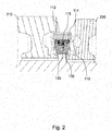
Fig. 2 depicts an enlarged view of the upper portion of the cross-sectional view ofFig. 1 , wherein the actuator is still in the neutral position. This cross-sectional view shows alsocoil windings 113 of thestator 112 that are provided at different angular portions of an exemplary ring-shaped stator 112 (see alsoFig. 4 ). - The embodiment of the present invention depicted in
Fig. 1 andFig. 2 implements a particular rotational-translational converter 120 which is placed between thestator 112 and therotor 114 of theelectric motor 110. Thisconverter 120 uses an exemplary threaded connection in the air gap of theelectric motor unit 110 between thestator 112 and therotor 114. The rotational-translational converter 120 provides also a guiding functionality so that there is no need of having an additional bearing for therotor 114. Instead, theconverter 120 itself provides this bearing function. - In particular, the
electric motor unit 110 and theconverter 120 may be formed as a single unit without having any additional components. This allows to integrate the electromechanical actuator even at positions where only limited place is available. Thestator 112 may be fixed relative to the housing so that the rotation of therotor 114 will result in an axial movement relative to the housing, which in turn moves theactuation member 130 to a desired position. Theactuation member 130 may be formed as a sliding sleeve to provide an exemplary gear shift of a gear unit or provides an actuation for a clutch or for a brake. - Furthermore, in the depicted embodiment an
exemplary recess 135 of theactuation member 130 receives aprotrusion 115 of therotor 114 providing the axial coupling between theactuation member 130 and therotor 114 so that both components perform axial movements together. Therecess 135 may be circular around theactuation member 130 so that theactuation member 130 may rotate freely inside therotor 114. - It is understood that the depicted threaded connection and the protrusion/recess coupling represent merely examples. A person skilled in the art will easily envision further couplings/connections that provide the same functions.
-
Fig. 3A and Fig. 3B depict the actuator when it is in the engaged position: inFig. 3A the engagement is between thefirst gear wheel 210 and therotary shaft 230; and inFig. 3B the engagement is between thesecond gear wheel 220 and therotary shaft 230. - These engagements are provided by a rotation of the rotor 214 that moves axially the
actuation member 130 in the corresponding engagement position. In order to move theactuation member 130, theelectric motor unit 110 may provide rotations in different directions resulting in opposite angular momentums which are converted by the exemplary threads into different translational forces/movements F of therotor 114 together with theactuation member 130 relative to thestator 112. - It is of particularly advantage if the
converter 120 has the self-locking feature, which may be achieved, for example, by using particular thread connections. If this is not the case, further measures may be implemented to keep theactuation member 130 in a desired (engaged) position so that theelectric motor unit 110 may not be active all the time to maintain the axial position of the actuation member. - Alternatively, if there is no threaded connection between the
rotor 114 andstator 112, but rather a pin/groove or pin/cam connection the shape of the groove or cam determines in which direction and how strongly therotor 114 moves axially upon an actuation of theelectric motor unit 110. - A pin/groove connection may likewise be used to implement a non-linear conversion characteristics, for example by adjusting the pitch of the groove accordingly. As a result, the
rotor 114 may move at first very fast in the axial direction followed by a slow, final axial movement (or vice versa). In addition, the groove may have an almost zero pitch at the end, thereby implementing a locking mechanism. Theactuation member 130 cannot move back by itself if the thread pitch is zero and a rotation will be needed by theelectric motor unit 110 to return theactuation member 130 in the neutral position shown inFig. 1 orFig. 2 . - The pin/cam connection provide the advantage that the
electric motor unit 110 need to move only in one direction. For example, starting with the neutral position, after a rotation by 90° theactuation member 130 may arrive at the first engagement position (seeFig. 3A ), after 180° theactuation member 130 may arrive again at the neutral engagement position and after 270° at the second engagement position (seeFig. 3B ). For this connection too, the maximum and minimum of the cam (e.g. at 90° and 270° rotation) provide a stable position yielding a natural locking mechanism at these engagement position. - It is understood that the different connections can be combined or adapted and the depicted threaded connection represents merely one example. A person skilled in the art will easily envision further connections that provide the same functions.
-
Fig. 4 depicts a view on thestator 112 with a plurality ofcoil winding sections 113 which are separated by sections where theconverter 120 is provided. In the depicted embodiment thestator 112 has a ring shape with a plurality ofconverter sections 120 each providing a threaded portion on the internal surface of thestator 112 that faces the rotor 114 (not shown inFig. 4 ) when inserted inside the ring. - This depicted ring may be an electric motor stator lamination which may be made from electric steel. The
coil windings 113 may also be made as conventional electric machine windings (for example using copper windings). In addition, theconverter portions 120 of thestator 112 may be nonmagnetic (or even nonmetallic) inserts which represent the fixed part of the rotational-translational converter 120. - The
rotor 114 may be formed as a solid ring including the moving part of theconverter 120, which may comprise a corresponding male thread. In additional, permanent magnetics may be placed inside therotor 114, if needed. -
Fig. 5 depicts another embodiment of thestator 112, wherein thestator 112 is not made by a closed ring structure, but by an open outer ring. This embodiment is, in particular, of advantage if the space available is only limited so that the open ring can be squeezed together to insert it into a respective opening of the housing. - All other parts and functions as described previously are identical for the embodiment shown in
Fig. 5 . - The described embodiments of the present invention are particularly advantageous for electric vehicles and can be integrated in various vehicle units such are gear units, clutches, brakes, etc. - even if only a limited space is available.
- The description and drawings merely illustrate the principles of the disclosure. It will thus be appreciated that those skilled in the art will be able to devise various arrangements that, although not explicitly described or shown herein, embody the principles of the disclosure and are included within its scope.
- Furthermore, while each embodiment may stand on its own as a separate example, it is to be noted that in other embodiments the defined features can be combined differently, i.e. a particular feature described in one embodiment may also be realized in other embodiments. Such combinations are covered by the disclosure herein unless it is stated that a specific combination is not intended.
-
- 110
- electric motor unit
- 112
- stator
- 113
- coil windings
- 114
- rotor
- 115
- protrusion of rotor
- 120
- converter
- 130
- actuation member
- 131
- internal teeth of actuation member
- 135
- recess in actuation member
- 210, 220, 240
- gear wheels
- 212, 221
- teeth of gear wheels
- 230
- rotary shaft
- 231
- external teeth of the rotary shaft
Claims (11)
- An electromechanical actuator for a motor vehicle, comprising:- an electric motor unit (110) with a stator (112) and a rotor (114); and- a converter (120) to convert a rotation between said stator (112) and said rotor (114) into a translation enabling an actuation in said motor vehicle, wherein at least part of said converter (120) is arranged on a surface of said stator (112) facing said rotor (114),wherein the stator (112) represents a closed or an opened ring surrounding at least partially said rotor (114) and characterized in that the stator (112) includes a plurality of coil winding sections (113) which are separated in a circumferential direction of the stator (112) by sections where said part of said converter (120) is provided.
- The electromechanical actuator of claim 1,
characterized in that
said converter (120) comprises at least one of the following coupling elements: a thread, a pin to cam coupling, a pin in a groove coupling, two grooves with rolling elements in-between, another component providing a relative linear movement upon a relative rotation between said stator and said rotor. - The electromechanical actuator of claim 1 or claim 2,
characterized in that
said electric motor unit (110) and said converter (120) form one integrated unit. - The electromechanical actuator of one of the preceding claims,
characterized in that
said converter (120) acts as a bearing to hold said rotor (114) rotatable relative to said stator (112), wherein said stator (112) or said rotor (114) are configured to be relatively fixed to said motor vehicle (110). - The electromechanical actuator according to one of the preceding claims, characterized by
an actuation member (130) coupled to said converter (120) and placed concentrically or eccentrically to said rotor (114), the actuation member (130) being driven by said converter (120) to provide a linear force (F) for the actuation upon the rotation of said rotor (114). - The electromechanical actuator according to claim 5,
characterized in that
said actuation member (130) is axially fixed relative to said rotor (114) and is configured to rotate freely inside and relative to said rotor (114). - The electromagnetic actuator according to one of the preceding claims, characterized in that
said converter (120) is configured to provide a non-linear conversion characteristic. - The electromagnetic actuator according to claim 7,
characterized in that
said converter (120) is configured to provide a conversion characteristic such that a translation movement of said rotor (114) depends on its rotational direction only. - The electromagnetic actuator according to claim 7,
characterized in that
said converter (120) is configured to provide a conversion characteristic such that a translational movement of said rotor (114) changes while of said rotor (114) maintains a rotational direction. - The electromechanical actuator according to one of the preceding claims, characterized in that
said converter (120) is configured to provide a self-locking mechanism. - Vehicle, in particular a commercial vehicle, with at least one component selected from the following: a clutch, a gearbox, a counter shaft brake, a brake, characterized in that
said at least one component comprises an electromechanical actuator according to one of the preceding claims.
Priority Applications (1)
| Application Number | Priority Date | Filing Date | Title |
|---|---|---|---|
| EP18167274.2A EP3553926B1 (en) | 2018-04-13 | 2018-04-13 | Electromechanical actuator |
Applications Claiming Priority (1)
| Application Number | Priority Date | Filing Date | Title |
|---|---|---|---|
| EP18167274.2A EP3553926B1 (en) | 2018-04-13 | 2018-04-13 | Electromechanical actuator |
Publications (2)
| Publication Number | Publication Date |
|---|---|
| EP3553926A1 EP3553926A1 (en) | 2019-10-16 |
| EP3553926B1 true EP3553926B1 (en) | 2021-12-29 |
Family
ID=62001988
Family Applications (1)
| Application Number | Title | Priority Date | Filing Date |
|---|---|---|---|
| EP18167274.2A Active EP3553926B1 (en) | 2018-04-13 | 2018-04-13 | Electromechanical actuator |
Country Status (1)
| Country | Link |
|---|---|
| EP (1) | EP3553926B1 (en) |
Family Cites Families (5)
| Publication number | Priority date | Publication date | Assignee | Title |
|---|---|---|---|---|
| US5205179A (en) * | 1990-07-21 | 1993-04-27 | Ina Walzlager Schaeffler Kg | Speed changing device |
| DE10007847A1 (en) | 2000-02-21 | 2001-08-23 | Zahnradfabrik Friedrichshafen | Electromagnetic switching device |
| DE102006015688A1 (en) * | 2006-03-27 | 2007-10-04 | Getrag Getriebe- Und Zahnradfabrik Hermann Hagenmeyer Gmbh & Cie Kg | Actuator arrangement for axial shifting of actuator for shifting clutch arrangement, has rotor coupled with actuator in axial direction in form-fit manner, where rotor or actuator comprises projection gripped in groove of rotor or actuator |
| US9017419B1 (en) * | 2012-03-09 | 2015-04-28 | össur hf | Linear actuator |
| DE102012012656A1 (en) * | 2012-06-23 | 2013-12-24 | Volkswagen Aktiengesellschaft | Electric motor for steering device of motor vehicle, has rotor which is engaged with stator such that rotation of rotor generates translational movement |
-
2018
- 2018-04-13 EP EP18167274.2A patent/EP3553926B1/en active Active
Non-Patent Citations (1)
| Title |
|---|
| None * |
Also Published As
| Publication number | Publication date |
|---|---|
| EP3553926A1 (en) | 2019-10-16 |
Similar Documents
| Publication | Publication Date | Title |
|---|---|---|
| CN102834634B (en) | Coupling assembly | |
| JP6771595B2 (en) | Electric drive unit with parking lock unit and parking lock | |
| US9689438B2 (en) | Electromagnetic clutch device | |
| US8991582B2 (en) | Clutch actuator | |
| CN107763153B (en) | Planetary gear type two-speed transmission for electric vehicle | |
| KR20180038372A (en) | Differential limiting device for vehicle | |
| US10704689B2 (en) | Parking lock for a motor vehicle | |
| JP6327137B2 (en) | Rotary actuator | |
| US20120255385A1 (en) | Gear device and rotary actuator having the same | |
| JP2005059849A (en) | Clutch with permanent magnet actuator, and synchronizer | |
| US20150197231A1 (en) | Electric Brake Booster with Transmission Clearance Compensation | |
| CN109139846B (en) | Planetary roller screw transmission mechanism, actuator and separation system | |
| CN104249617B (en) | For the driving device of the roof module of motor vehicles | |
| EP3553926B1 (en) | Electromechanical actuator | |
| CN111373169B (en) | Clutch unit for a drive train having a form-fitting clutch and hybrid module having a clutch unit as a disconnect clutch | |
| CN104100660A (en) | Dry dual clutch transmission actuation system using electrical motor with force aided lever | |
| US11378183B2 (en) | Gearshift actuator | |
| EP2803800B1 (en) | Electric rotary actuator for an entry and exit device, in particular a door | |
| EP2977633A1 (en) | Engagement device and power transmission device | |
| WO2022107267A1 (en) | Power transmission device | |
| KR20170005442A (en) | Ball screw electromechanical actuator for a clutch | |
| US9046173B2 (en) | Transmission driving device | |
| KR101284253B1 (en) | Double clutch actuator | |
| JP2008174188A (en) | Electric actuator for parking lock device | |
| US20200072350A1 (en) | Rotary park lock |
Legal Events
| Date | Code | Title | Description |
|---|---|---|---|
| PUAI | Public reference made under article 153(3) epc to a published international application that has entered the european phase |
Free format text: ORIGINAL CODE: 0009012 |
|
| STAA | Information on the status of an ep patent application or granted ep patent |
Free format text: STATUS: THE APPLICATION HAS BEEN PUBLISHED |
|
| AK | Designated contracting states |
Kind code of ref document: A1 Designated state(s): AL AT BE BG CH CY CZ DE DK EE ES FI FR GB GR HR HU IE IS IT LI LT LU LV MC MK MT NL NO PL PT RO RS SE SI SK SM TR |
|
| AX | Request for extension of the european patent |
Extension state: BA ME |
|
| STAA | Information on the status of an ep patent application or granted ep patent |
Free format text: STATUS: REQUEST FOR EXAMINATION WAS MADE |
|
| 17P | Request for examination filed |
Effective date: 20200416 |
|
| RBV | Designated contracting states (corrected) |
Designated state(s): AL AT BE BG CH CY CZ DE DK EE ES FI FR GB GR HR HU IE IS IT LI LT LU LV MC MK MT NL NO PL PT RO RS SE SI SK SM TR |
|
| STAA | Information on the status of an ep patent application or granted ep patent |
Free format text: STATUS: EXAMINATION IS IN PROGRESS |
|
| 17Q | First examination report despatched |
Effective date: 20201112 |
|
| GRAP | Despatch of communication of intention to grant a patent |
Free format text: ORIGINAL CODE: EPIDOSNIGR1 |
|
| STAA | Information on the status of an ep patent application or granted ep patent |
Free format text: STATUS: GRANT OF PATENT IS INTENDED |
|
| RIC1 | Information provided on ipc code assigned before grant |
Ipc: H02K 7/06 20060101AFI20210630BHEP Ipc: H02K 7/08 20060101ALI20210630BHEP Ipc: F16H 61/32 20060101ALI20210630BHEP Ipc: F16H 61/28 20060101ALI20210630BHEP |
|
| INTG | Intention to grant announced |
Effective date: 20210723 |
|
| RIN1 | Information on inventor provided before grant (corrected) |
Inventor name: NEMETH, HUBA Inventor name: MLINARCSEK, CSABA Inventor name: KOVACSIK, PETER Inventor name: RAPP, TAMAS Inventor name: KOKREHEL, CSABA Inventor name: TOTH, JANOS |
|
| GRAS | Grant fee paid |
Free format text: ORIGINAL CODE: EPIDOSNIGR3 |
|
| GRAA | (expected) grant |
Free format text: ORIGINAL CODE: 0009210 |
|
| STAA | Information on the status of an ep patent application or granted ep patent |
Free format text: STATUS: THE PATENT HAS BEEN GRANTED |
|
| AK | Designated contracting states |
Kind code of ref document: B1 Designated state(s): AL AT BE BG CH CY CZ DE DK EE ES FI FR GB GR HR HU IE IS IT LI LT LU LV MC MK MT NL NO PL PT RO RS SE SI SK SM TR |
|
| REG | Reference to a national code |
Ref country code: GB Ref legal event code: FG4D |
|
| REG | Reference to a national code |
Ref country code: CH Ref legal event code: EP |
|
| REG | Reference to a national code |
Ref country code: AT Ref legal event code: REF Ref document number: 1459412 Country of ref document: AT Kind code of ref document: T Effective date: 20220115 |
|
| REG | Reference to a national code |
Ref country code: IE Ref legal event code: FG4D |
|
| REG | Reference to a national code |
Ref country code: DE Ref legal event code: R096 Ref document number: 602018028693 Country of ref document: DE |
|
| REG | Reference to a national code |
Ref country code: LT Ref legal event code: MG9D |
|
| PG25 | Lapsed in a contracting state [announced via postgrant information from national office to epo] |
Ref country code: RS Free format text: LAPSE BECAUSE OF FAILURE TO SUBMIT A TRANSLATION OF THE DESCRIPTION OR TO PAY THE FEE WITHIN THE PRESCRIBED TIME-LIMIT Effective date: 20211229 Ref country code: LT Free format text: LAPSE BECAUSE OF FAILURE TO SUBMIT A TRANSLATION OF THE DESCRIPTION OR TO PAY THE FEE WITHIN THE PRESCRIBED TIME-LIMIT Effective date: 20211229 Ref country code: FI Free format text: LAPSE BECAUSE OF FAILURE TO SUBMIT A TRANSLATION OF THE DESCRIPTION OR TO PAY THE FEE WITHIN THE PRESCRIBED TIME-LIMIT Effective date: 20211229 Ref country code: BG Free format text: LAPSE BECAUSE OF FAILURE TO SUBMIT A TRANSLATION OF THE DESCRIPTION OR TO PAY THE FEE WITHIN THE PRESCRIBED TIME-LIMIT Effective date: 20220329 |
|
| REG | Reference to a national code |
Ref country code: NL Ref legal event code: MP Effective date: 20211229 |
|
| REG | Reference to a national code |
Ref country code: AT Ref legal event code: MK05 Ref document number: 1459412 Country of ref document: AT Kind code of ref document: T Effective date: 20211229 |
|
| PG25 | Lapsed in a contracting state [announced via postgrant information from national office to epo] |
Ref country code: SE Free format text: LAPSE BECAUSE OF FAILURE TO SUBMIT A TRANSLATION OF THE DESCRIPTION OR TO PAY THE FEE WITHIN THE PRESCRIBED TIME-LIMIT Effective date: 20211229 Ref country code: NO Free format text: LAPSE BECAUSE OF FAILURE TO SUBMIT A TRANSLATION OF THE DESCRIPTION OR TO PAY THE FEE WITHIN THE PRESCRIBED TIME-LIMIT Effective date: 20220329 Ref country code: LV Free format text: LAPSE BECAUSE OF FAILURE TO SUBMIT A TRANSLATION OF THE DESCRIPTION OR TO PAY THE FEE WITHIN THE PRESCRIBED TIME-LIMIT Effective date: 20211229 Ref country code: HR Free format text: LAPSE BECAUSE OF FAILURE TO SUBMIT A TRANSLATION OF THE DESCRIPTION OR TO PAY THE FEE WITHIN THE PRESCRIBED TIME-LIMIT Effective date: 20211229 Ref country code: GR Free format text: LAPSE BECAUSE OF FAILURE TO SUBMIT A TRANSLATION OF THE DESCRIPTION OR TO PAY THE FEE WITHIN THE PRESCRIBED TIME-LIMIT Effective date: 20220330 |
|
| PG25 | Lapsed in a contracting state [announced via postgrant information from national office to epo] |
Ref country code: NL Free format text: LAPSE BECAUSE OF FAILURE TO SUBMIT A TRANSLATION OF THE DESCRIPTION OR TO PAY THE FEE WITHIN THE PRESCRIBED TIME-LIMIT Effective date: 20211229 |
|
| PG25 | Lapsed in a contracting state [announced via postgrant information from national office to epo] |
Ref country code: SM Free format text: LAPSE BECAUSE OF FAILURE TO SUBMIT A TRANSLATION OF THE DESCRIPTION OR TO PAY THE FEE WITHIN THE PRESCRIBED TIME-LIMIT Effective date: 20211229 Ref country code: SK Free format text: LAPSE BECAUSE OF FAILURE TO SUBMIT A TRANSLATION OF THE DESCRIPTION OR TO PAY THE FEE WITHIN THE PRESCRIBED TIME-LIMIT Effective date: 20211229 Ref country code: RO Free format text: LAPSE BECAUSE OF FAILURE TO SUBMIT A TRANSLATION OF THE DESCRIPTION OR TO PAY THE FEE WITHIN THE PRESCRIBED TIME-LIMIT Effective date: 20211229 Ref country code: PT Free format text: LAPSE BECAUSE OF FAILURE TO SUBMIT A TRANSLATION OF THE DESCRIPTION OR TO PAY THE FEE WITHIN THE PRESCRIBED TIME-LIMIT Effective date: 20220429 Ref country code: ES Free format text: LAPSE BECAUSE OF FAILURE TO SUBMIT A TRANSLATION OF THE DESCRIPTION OR TO PAY THE FEE WITHIN THE PRESCRIBED TIME-LIMIT Effective date: 20211229 Ref country code: EE Free format text: LAPSE BECAUSE OF FAILURE TO SUBMIT A TRANSLATION OF THE DESCRIPTION OR TO PAY THE FEE WITHIN THE PRESCRIBED TIME-LIMIT Effective date: 20211229 Ref country code: CZ Free format text: LAPSE BECAUSE OF FAILURE TO SUBMIT A TRANSLATION OF THE DESCRIPTION OR TO PAY THE FEE WITHIN THE PRESCRIBED TIME-LIMIT Effective date: 20211229 |
|
| PG25 | Lapsed in a contracting state [announced via postgrant information from national office to epo] |
Ref country code: PL Free format text: LAPSE BECAUSE OF FAILURE TO SUBMIT A TRANSLATION OF THE DESCRIPTION OR TO PAY THE FEE WITHIN THE PRESCRIBED TIME-LIMIT Effective date: 20211229 Ref country code: AT Free format text: LAPSE BECAUSE OF FAILURE TO SUBMIT A TRANSLATION OF THE DESCRIPTION OR TO PAY THE FEE WITHIN THE PRESCRIBED TIME-LIMIT Effective date: 20211229 |
|
| PG25 | Lapsed in a contracting state [announced via postgrant information from national office to epo] |
Ref country code: IS Free format text: LAPSE BECAUSE OF FAILURE TO SUBMIT A TRANSLATION OF THE DESCRIPTION OR TO PAY THE FEE WITHIN THE PRESCRIBED TIME-LIMIT Effective date: 20220429 |
|
| REG | Reference to a national code |
Ref country code: DE Ref legal event code: R097 Ref document number: 602018028693 Country of ref document: DE |
|
| PG25 | Lapsed in a contracting state [announced via postgrant information from national office to epo] |
Ref country code: DK Free format text: LAPSE BECAUSE OF FAILURE TO SUBMIT A TRANSLATION OF THE DESCRIPTION OR TO PAY THE FEE WITHIN THE PRESCRIBED TIME-LIMIT Effective date: 20211229 Ref country code: AL Free format text: LAPSE BECAUSE OF FAILURE TO SUBMIT A TRANSLATION OF THE DESCRIPTION OR TO PAY THE FEE WITHIN THE PRESCRIBED TIME-LIMIT Effective date: 20211229 |
|
| PLBE | No opposition filed within time limit |
Free format text: ORIGINAL CODE: 0009261 |
|
| STAA | Information on the status of an ep patent application or granted ep patent |
Free format text: STATUS: NO OPPOSITION FILED WITHIN TIME LIMIT |
|
| REG | Reference to a national code |
Ref country code: CH Ref legal event code: PL |
|
| 26N | No opposition filed |
Effective date: 20220930 |
|
| GBPC | Gb: european patent ceased through non-payment of renewal fee |
Effective date: 20220413 |
|
| REG | Reference to a national code |
Ref country code: BE Ref legal event code: MM Effective date: 20220430 |
|
| PG25 | Lapsed in a contracting state [announced via postgrant information from national office to epo] |
Ref country code: MC Free format text: LAPSE BECAUSE OF FAILURE TO SUBMIT A TRANSLATION OF THE DESCRIPTION OR TO PAY THE FEE WITHIN THE PRESCRIBED TIME-LIMIT Effective date: 20211229 Ref country code: LU Free format text: LAPSE BECAUSE OF NON-PAYMENT OF DUE FEES Effective date: 20220413 Ref country code: LI Free format text: LAPSE BECAUSE OF NON-PAYMENT OF DUE FEES Effective date: 20220430 Ref country code: FR Free format text: LAPSE BECAUSE OF NON-PAYMENT OF DUE FEES Effective date: 20220430 Ref country code: CH Free format text: LAPSE BECAUSE OF NON-PAYMENT OF DUE FEES Effective date: 20220430 Ref country code: GB Free format text: LAPSE BECAUSE OF NON-PAYMENT OF DUE FEES Effective date: 20220413 |
|
| PG25 | Lapsed in a contracting state [announced via postgrant information from national office to epo] |
Ref country code: SI Free format text: LAPSE BECAUSE OF FAILURE TO SUBMIT A TRANSLATION OF THE DESCRIPTION OR TO PAY THE FEE WITHIN THE PRESCRIBED TIME-LIMIT Effective date: 20211229 Ref country code: BE Free format text: LAPSE BECAUSE OF NON-PAYMENT OF DUE FEES Effective date: 20220430 |
|
| PG25 | Lapsed in a contracting state [announced via postgrant information from national office to epo] |
Ref country code: IE Free format text: LAPSE BECAUSE OF NON-PAYMENT OF DUE FEES Effective date: 20220413 |
|
| PG25 | Lapsed in a contracting state [announced via postgrant information from national office to epo] |
Ref country code: IT Free format text: LAPSE BECAUSE OF FAILURE TO SUBMIT A TRANSLATION OF THE DESCRIPTION OR TO PAY THE FEE WITHIN THE PRESCRIBED TIME-LIMIT Effective date: 20211229 |
|
| P01 | Opt-out of the competence of the unified patent court (upc) registered |
Effective date: 20230523 |
|
| PGFP | Annual fee paid to national office [announced via postgrant information from national office to epo] |
Ref country code: DE Payment date: 20230418 Year of fee payment: 6 |
|
| PG25 | Lapsed in a contracting state [announced via postgrant information from national office to epo] |
Ref country code: HU Free format text: LAPSE BECAUSE OF FAILURE TO SUBMIT A TRANSLATION OF THE DESCRIPTION OR TO PAY THE FEE WITHIN THE PRESCRIBED TIME-LIMIT; INVALID AB INITIO Effective date: 20180413 |