EP3553891A1 - Busbar, assembly of at least two busbars and method for connecting the busbars - Google Patents
Busbar, assembly of at least two busbars and method for connecting the busbars Download PDFInfo
- Publication number
- EP3553891A1 EP3553891A1 EP19167534.7A EP19167534A EP3553891A1 EP 3553891 A1 EP3553891 A1 EP 3553891A1 EP 19167534 A EP19167534 A EP 19167534A EP 3553891 A1 EP3553891 A1 EP 3553891A1
- Authority
- EP
- European Patent Office
- Prior art keywords
- contact
- busbars
- busbar
- tab
- receptacle
- Prior art date
- Legal status (The legal status is an assumption and is not a legal conclusion. Google has not performed a legal analysis and makes no representation as to the accuracy of the status listed.)
- Granted
Links
- 238000000034 method Methods 0.000 title claims abstract description 8
- 238000004049 embossing Methods 0.000 claims abstract description 17
- 239000004020 conductor Substances 0.000 claims abstract description 13
- 230000000712 assembly Effects 0.000 claims abstract description 8
- 238000000429 assembly Methods 0.000 claims abstract description 8
- 238000005304 joining Methods 0.000 claims description 18
- 238000010276 construction Methods 0.000 claims description 2
- 210000002414 leg Anatomy 0.000 description 15
- 239000000463 material Substances 0.000 description 6
- 238000005452 bending Methods 0.000 description 5
- 238000005260 corrosion Methods 0.000 description 2
- 230000007797 corrosion Effects 0.000 description 2
- 230000007774 longterm Effects 0.000 description 2
- 238000004080 punching Methods 0.000 description 2
- RYGMFSIKBFXOCR-UHFFFAOYSA-N Copper Chemical compound [Cu] RYGMFSIKBFXOCR-UHFFFAOYSA-N 0.000 description 1
- 241000722921 Tulipa gesneriana Species 0.000 description 1
- 229910052782 aluminium Inorganic materials 0.000 description 1
- XAGFODPZIPBFFR-UHFFFAOYSA-N aluminium Chemical compound [Al] XAGFODPZIPBFFR-UHFFFAOYSA-N 0.000 description 1
- 238000006243 chemical reaction Methods 0.000 description 1
- 150000001875 compounds Chemical class 0.000 description 1
- 229910052802 copper Inorganic materials 0.000 description 1
- 239000010949 copper Substances 0.000 description 1
- 238000003780 insertion Methods 0.000 description 1
- 230000037431 insertion Effects 0.000 description 1
- 238000009434 installation Methods 0.000 description 1
- 238000004519 manufacturing process Methods 0.000 description 1
- 229910052751 metal Inorganic materials 0.000 description 1
- 239000002184 metal Substances 0.000 description 1
- 210000000689 upper leg Anatomy 0.000 description 1
- 238000003466 welding Methods 0.000 description 1
Images


Classifications
-
- H—ELECTRICITY
- H01—ELECTRIC ELEMENTS
- H01R—ELECTRICALLY-CONDUCTIVE CONNECTIONS; STRUCTURAL ASSOCIATIONS OF A PLURALITY OF MUTUALLY-INSULATED ELECTRICAL CONNECTING ELEMENTS; COUPLING DEVICES; CURRENT COLLECTORS
- H01R4/00—Electrically-conductive connections between two or more conductive members in direct contact, i.e. touching one another; Means for effecting or maintaining such contact; Electrically-conductive connections having two or more spaced connecting locations for conductors and using contact members penetrating insulation
- H01R4/26—Connections in which at least one of the connecting parts has projections which bite into or engage the other connecting part in order to improve the contact
-
- B—PERFORMING OPERATIONS; TRANSPORTING
- B21—MECHANICAL METAL-WORKING WITHOUT ESSENTIALLY REMOVING MATERIAL; PUNCHING METAL
- B21D—WORKING OR PROCESSING OF SHEET METAL OR METAL TUBES, RODS OR PROFILES WITHOUT ESSENTIALLY REMOVING MATERIAL; PUNCHING METAL
- B21D39/00—Application of procedures in order to connect objects or parts, e.g. coating with sheet metal otherwise than by plating; Tube expanders
- B21D39/03—Application of procedures in order to connect objects or parts, e.g. coating with sheet metal otherwise than by plating; Tube expanders of sheet metal otherwise than by folding
- B21D39/037—Interlocking butt joints
-
- H—ELECTRICITY
- H01—ELECTRIC ELEMENTS
- H01R—ELECTRICALLY-CONDUCTIVE CONNECTIONS; STRUCTURAL ASSOCIATIONS OF A PLURALITY OF MUTUALLY-INSULATED ELECTRICAL CONNECTING ELEMENTS; COUPLING DEVICES; CURRENT COLLECTORS
- H01R11/00—Individual connecting elements providing two or more spaced connecting locations for conductive members which are, or may be, thereby interconnected, e.g. end pieces for wires or cables supported by the wire or cable and having means for facilitating electrical connection to some other wire, terminal, or conductive member, blocks of binding posts
- H01R11/01—Individual connecting elements providing two or more spaced connecting locations for conductive members which are, or may be, thereby interconnected, e.g. end pieces for wires or cables supported by the wire or cable and having means for facilitating electrical connection to some other wire, terminal, or conductive member, blocks of binding posts characterised by the form or arrangement of the conductive interconnection between the connecting locations
-
- H—ELECTRICITY
- H01—ELECTRIC ELEMENTS
- H01R—ELECTRICALLY-CONDUCTIVE CONNECTIONS; STRUCTURAL ASSOCIATIONS OF A PLURALITY OF MUTUALLY-INSULATED ELECTRICAL CONNECTING ELEMENTS; COUPLING DEVICES; CURRENT COLLECTORS
- H01R4/00—Electrically-conductive connections between two or more conductive members in direct contact, i.e. touching one another; Means for effecting or maintaining such contact; Electrically-conductive connections having two or more spaced connecting locations for conductors and using contact members penetrating insulation
- H01R4/06—Riveted connections
Definitions
- the present invention relates to an arrangement of a first busbar and a second busbar for electrically connecting electrical conductors and / or assemblies, wherein the busbars each have at least one surface which are spanned in a longitudinal direction and an extension direction.
- the present invention further relates to a busbar for such an arrangement and to a method for electrically connecting at least two such busbars.
- Busbars are used to connect electrical conductors and / or assemblies. At the junctions of the busbars with each other and to the conductors and / or assemblies of the electrical contact must be permanently ensured reliable. Depending on the field of application, for example in the manufacturing industry, the connection should moreover be simple and quick to carry out, in order to enable rapid conversion of the assemblies and installations.
- Bus bars are regularly bolted, welded or riveted to one another. Care must be taken to the materials used, in particular the screws and / or sleeves, so that the contact is guaranteed in the long term, if different materials despite different temperature and corrosion behavior.
- the contact with electrical conductors is often produced by means of a crimp connection. Screwing, welding or riveting are relatively expensive joining techniques.
- the publication DE 20 2013 103 444 U1 shows, for example, a w-shaped contact element, the three contact tulips are provided for electrically connecting busbars of a particular outwardly guided bus system.
- an approximately s-shaped clamping spring is used for electrically connecting busbars of a bus system, which is routed externally in particular, to series components of a series modular arrangement.
- Object of the present invention is therefore to provide a method with the busbars permanently, easily, quickly and reliably connected to each other, and a busbar for it.
- first busbar and a second busbar are each provided for electrically connecting electrical conductors and / or assemblies.
- the busbars each have at least one surface, which are spanned in a longitudinal direction and an extension direction.
- the busbars of this arrangement can be produced very cost-effectively from a flat strip material as a punching and bending component.
- a sheet of copper or aluminum is preferably used.
- the busbars are not non-destructively connected to one another detachably. The preferred choice of busbars of the same material, the contact is guaranteed long term.
- the contact tabs of the busbars are designed to correspond to the contact receptacles of the busbars.
- the contact lugs of the busbars each have a contour which is formed corresponding to the contour of the contact receptacles.
- the contact lug of a busbar can be inserted, inserted or latched into the correspondingly formed contact receptacle of the other busbar.
- busbars are constructed identical in a first preferred embodiment. However, it is also preferred that bus bars are combined with each other, which have a different cross-section, and / or their number of contact tabs and / or contact receptacles are different. Particularly preferably, the first bus bar on only one or more contact receptacles, wherein the second bus bar has only one or more contact tabs.
- the busbars are each preferably flat, linear or L-shaped, S-shaped or U-shaped in cross-section. In cross-section L, S or U-shaped design, the busbars on at least two surfaces, which are available for arranging at least one contact tab and / or at least one contact. In this case, the flat, linear, L, S or U-shaped busbars can be combined with each other as desired.
- a width of the contact tab is at least selectively or partially almost equal to or only slightly smaller than a width of the contact.
- the contact tab in this area fits almost exactly in the contact.
- stamping the mechanical positive connection and electrical contact is made at least in this area.
- two opposing contact points or contact areas can be specifically defined. The current path is then passed from the one bus bar through defined contact points or areas in the second bus bar.
- the contact tab and / or the contact receptacle of the busbars each have a contact neck on which a contact head is arranged.
- the contact tab snaps due to the tapering at the contact neck Contour into the contact. It is then without being embossed to be held captive and can not solve automatically against the joining direction from the contact.
- the contact head of the contact of the busbars in the joining direction is formed longer than the contact head of the contact tab of the busbars.
- the contact tab can be moved in and against the joining direction before the busbars are stamped together. This allows for the mounting of the busbars with each other a tolerance compensation in the joining direction.
- the busbars each comprise two surfaces, on each of which at least one contact tab, preferably two contact tabs, and / or in which at least one contact, preferably two contact receptacles, are arranged. It is further preferred that the at least one contact tab and / or the at least one contact receiving one of the two surfaces in the longitudinal direction relative to the at least one contact tab and / or the at least one contact receiving the other of the two surfaces is arranged offset. As a result, nesting of multiple busbars is possible.
- busbars In this case, a U-shaped design of the busbars is particularly preferred. Two U-shaped busbars can then be arranged one above the other. One of the busbars each surrounded interior is preferably used for electrically contacting attaching electrical conductors.
- the object is further achieved with a busbar for such an arrangement.
- the bus bar has at least one surface which is spanned in a longitudinal direction and an extension direction. Furthermore, it has at least one contact lug extending from one edge of the surface and / or at least one contact arranged in the surface.
- the contact tab and / or the contact of the busbar are provided for embossing with a contact and / or a contact tab of another corresponding busbar.
- the embossing can be carried out advantageously and simply with an embossing die which is delivered perpendicular to the surface of the contact tab on the contact tab and radially expands so that it applies radially inward to the inner periphery of the contact, which can be held down accordingly.
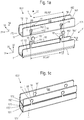
- Fig. 1 (a) shows an assembly 10 of a first busbar 1 and a second busbar 1 'of a first embodiment of the invention in an unassembled state U.
- the busbars 1, 1' are formed in cross-section U-shaped. They extend in a longitudinal direction 31 and surround an inner space 100, which is usable for the electrically contacting arrangement of electrical conductors (not shown).
- Both busbars 1, 1 ' have two surfaces 12, 13, 12', 13 ', here also called leg surfaces, each extending in the longitudinal direction 31 and a joining direction 32.
- the leg surfaces 12, 13, 12 ', 13' of the busbars 1, 1 ' are connected to each other by a connecting surface 11, 11', which extends in the longitudinal direction 31 and a transverse direction 33.
- the busbars 1, 1 ' are integrally formed as a punching bending component of a metal sheet.
- the leg surfaces 12, 12 ', 13, 13' by bending the sheet by about a right angle (not shown) relative to the connecting surface 11, 11 'is formed. Therefore, the leg surfaces 12, 13, 12 ', 13' in each case at a bending edge 171, 172, 171 ', 172', which extends in the longitudinal direction 31, with the connecting surface 11, 11 'are connected.
- two recesses are respectively arranged, which are provided as a contact receptacles 14 and serve to receive contact tabs 15 'of the second busbar 1'.
- a contour of the contact tabs 15 'of the second busbar 1' is corresponding to a contour formed the contact receptacles 14 of the first busbar 1, so that the contact tabs 15 'respectively in the contact receptacles 14 fit.
- the contact receptacles 14 each extend from the bending edge 171, 172 into the leg surface 12, 13 of the first busbar 1.
- the contact receptacles 14 of the opposite leg surfaces 12, 13 each have the same distance A1, A2 to each other.
- the contact receptacles 14 of the one of the two leg surfaces 12, 13 in the longitudinal direction 31 relative to the contact receptacles 14 of the other of the two surfaces 12, 13 offset by an offset .DELTA.A each other.
- two contact tabs 15' are arranged in an analogous manner. Also, the contact tabs 15 'have on the leg surfaces 12', 13 'in each case the same distance A1', A2 'to each other. However, the contact tabs 15 'of the one of the two leg surfaces 12', 13 'in the longitudinal direction 31 relative to the contact tabs 15' of the other of the two surfaces 12 ', 13' offset by an offset .DELTA.A 'to each other.
- the offset .DELTA.A, .DELTA.A ' is the same here for both busbars 1, 1'.
- the busbars 1, 1 ' can be arranged one above the other. In addition, they are nestable with each other, so that they are arranged at an angle to each other.
- further busbars (not shown) with these two busbars 1, 1 'can be connected. In each case, only the contact tabs 15 'one of the two leg surfaces 12', 13 'of the second busbar 1' with the contact receptacles 14 one of the two leg surfaces 13, 12 of the first busbar 1 connected to each other.
- a length L of the two busbars 1, 1 'and a width B of the two busbars 1, 1' are the same here.
- different widths and / or different lengths busbars 1, 1 ' are connected to each other, as long as the distance A1, A2, A1', A2 'of the contact tabs 15' and the contact receptacles 14 are formed to match each other, and the contours of the contact tabs 15th 'and the contact receptacles 14 correspond to each other.
- both the contact tabs 15' and the contact receptacles 14 each have a contact head 152 ', 142 and a contact neck 151', 141.
- the contact neck 151 ', 141 is formed narrower relative to the contact head 152', 142.
- the contact tab 15 'overall has a smaller contour than the contact receptacle 14, so that it can be inserted or latched into the contact receptacle 14.
- Fig. 1 (b) shows the arrangement 10 of Fig. 1 (a) during assembly.
- the contact tabs 15 'of the second busbar 1' are engaged in the contact receptacles 14 of the first busbar 1.
- a first of the two contact tabs 15 'one of the two leg surfaces 13' of the second busbar 1 'in the contact receptacle 14 of the first busbar 1 is shown.
- the contact lug 15 ' is not yet embossed with the contact receptacle 14, so that the busbars 1, 1' at this contact tab 15 'and contact receptacle 14 are not yet mechanically positively connected and not yet defined electrically contacting each other.
- the first of the two contact tabs 15 'and their contact receptacle 14 are shown during embossing with an embossing tool 2.
- a counter-tool (not shown) is arranged in the interior 100 (not visible here) that holds the contact tab 15 'in the contact receptacle 14.
- the embossing tool 2 is then pressed onto the contact tab 15 'with pressure, for example with a hammer (not shown).
- it is positively and preferably also non-positively connected and good electrically conductive with the contact receptacle 14.
- the third section (III) shows the second of the two contact lugs 15 'of the leg surface 13' of the second busbar 1 'in the contact receptacle 14 of the first busbar 1 enlarged.
- This contact plate 15 'and Druckability14 are already embossed with each other.
- the third section (III) therefore shows the connection state V.
- Fig. 1 (c) shows the two busbars 1, 1 'in the connection state V. All contact lugs 15' of the second busbar 1 'are each embossed with their contact receptacles 14 of the first busbar 1.
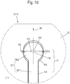
- Fig. 1 (d) shows the first part of the Fig. 1 (b) enlarged again.
- the contact tab 15 ' has a substantially round contact head 152'.
- the contact head 142 of the contact receptacle 14 here approximately centrally in the joining direction 30, an extension 143, so that the contact head 142 is formed here approximately elliptical.
- the contact tab 15 ' is at least slightly displaceable in the contact receptacle 14 in or against the joining direction 30.
- an at least slight play in or against the joining direction 30 can be compensated.
- a width b5 'of the contact head 152' of the contact tab 15 'in its center M5' is only slightly smaller than a width b4 of the contact head 142 of the contact receptacle 14, so that when embossing in this area a mechanical positive connection, and thus an electrical connection point, can be produced in a defined manner.
- Fig. 2 shows in (a) another embodiment of an inventive arrangement 10 in the connection state V and in (b) an enlarged section of (a). It is visible that the extension 143 of the contact head 142 of the contact receptacle 14 of the first busbar 1 is significantly larger than in the Fig. 1 (d) , As a result, the contact lug 15 'of the second busbar 1' can be displaced significantly further in or against the joining direction 30. The position of the second busbar 1 'relative to the first busbar 1 is therefore significantly more adaptable in or against the joining direction 30.
- the in the Fig. 3 (a) - (c) illustrated embodiments of the arrangements 10 use flat conductor rails 1, 1 '.
- the busbars 1, 1 'therefore each have only one surface 12, 12', on or in the contact tabs 15,15 'and / or contact receptacles 14, 14' are arranged.
- Fig. 3 (a) are the two busbars 1, 1 'of the arrangement 10 of identical design.
- This is followed in each case by a contact lug 15, 15 'a contact receptacle 14, 14'.
- the contact tabs 15, 15 'at one edge 161, 161' relative to those at the other edge 162, 162 'offset.
- the offset (not designated) is selected so that a contact lug 15, 15 'at one edge 161, 161' is in each case a contact receptacle 14, 14 'at the other edge 162, 162' opposite.
- two contact lugs 15 are arranged at the opposite edges 161, 162 of the first busbar 1, while at the opposite edges 161 ', 162' of the second busbar 1 'each two contact receptacles 14' are arranged.
- the contact tabs 15 or contact receptacles 14 'arranged on the opposite edges 161, 162, 161', 162 'of the same busbar 1, 1' are offset from each other.
- a shielding potential surface can be formed.
- the arrangement can also be used for electrically conductive connection with electrical conductors.
- busbars 1, 1 'of Fig. 3 (a) and (B) have the busbars 1, 1 'of the arrangement 10 of Fig. 3 (c) in each case only one contact tab 15, 15 'at one edge 161, 161', and a contact receptacle 14, 14 'at the other edge 162, 162' on.
- the contact head 152, 152 ', 142, 142' of the contact tab 15, 15 'and the contact receptacle 14, 14' is not round or elliptical, but rectangular.
- the contact tab 15, 15 'of a busbar 1, 1' after insertion into the contact receptacle 14, 14 'of the other busbar 1, 1' by embossing, in particular the contact heads 152, 152 ', 142, 142', mechanically positively connected and preferably also non-positively and electrically contacting with each other connectable.
- Fig. 4 (a) shows a further embodiment of an inventive arrangement in an assembled state.
- contact tab and contact are formed approximately L-shaped.
- the contact neck of the contact is wider by a distance ⁇ 31 than the contact neck of the contact lug.
- the contact head of the contact is about the same distance ⁇ 31 longer than the contact head of the contact tab.
- the second busbar is displaceable relative to the first busbar by the distance, here in or against the longitudinal direction. As a result, a game in or against the longitudinal direction can be compensated.
- FIG. 4 (b) an arrangement with a first and a second busbar 1, 1 'in the assembled state M, in which the contact tab 15' and the contact receptacle 14 no contact head 152 ', 142 have. But the contact tab 15 'and the contact receptacle 14 taper towards the edge 161, 162' of their busbar 1, 1 'out. After inserting the contact tab 15 'in the contact receptacle 14, the contact tab 15' is held captive in the contact receptacle 14 even without embossing even in this embodiment.
Abstract
Die vorliegende Erfindung betrifft eine Anordnung aus einer ersten Stromschiene und einer zweiten Stromschiene zum elektrischen Verbinden elektrischer Leiter und/oder Baugruppen, wobei die Stromschienen jeweils zumindest eine Fläche aufweisen, die in eine Längsrichtung und eine Erstreckungsrichtung aufgespannt sind, wobei die Stromschienen jeweils
• zumindest eine sich von einem Rand der Fläche aus erstreckende Kontaktlasche und/oder
• zumindest eine in der Fläche angeordnete Kontaktaufnahme
aufweisen, wobei zumindest eine Kontaktlasche der einen Stromschiene in zumindest einer Kontaktaufnahme der anderen Stromschiene angeordnet ist, und wobei die in die Kontaktaufnahme aufgenommene Kontaktlasche mit dieser durch eine Verprägung formschlüssig und vorzugsweise auch kraftschlüssig mechanisch und elektrisch kontaktierend verbunden ist. Die vorliegende Erfindung betrifft weiterhin eine Stromschiene für eine solche Anordnung sowie ein Verfahren zum elektrischen Verbinden von mindestens zwei solchen Stromschienen.

At least one contact tab extending from one edge of the surface and / or
• at least one arranged in the surface contact
wherein at least one contact lug of the one bus bar is arranged in at least one contact receptacle of the other bus bar, and wherein the contact tab received in the contact receptacle is mechanically and electrically contact-connected with the latter by an embossing in a form-fitting and preferably non-positive manner. The present invention further relates to a busbar for such an arrangement and to a method for electrically connecting at least two such busbars.
Description
Die vorliegende Erfindung betrifft eine Anordnung aus einer ersten Stromschiene und einer zweiten Stromschiene zum elektrischen Verbinden elektrischer Leiter und/oder Baugruppen, wobei die Stromschienen jeweils zumindest eine Fläche aufweisen, die in eine Längsrichtung und eine Erstreckungsrichtung aufgespannt sind. Die vorliegende Erfindung betrifft weiterhin eine Stromschiene für eine solche Anordnung sowie ein Verfahren zum elektrischen Verbinden von mindestens zwei solchen Stromschienen.The present invention relates to an arrangement of a first busbar and a second busbar for electrically connecting electrical conductors and / or assemblies, wherein the busbars each have at least one surface which are spanned in a longitudinal direction and an extension direction. The present invention further relates to a busbar for such an arrangement and to a method for electrically connecting at least two such busbars.
Stromschienen werden zum Verbinden von elektrischen Leitern und/oder Baugruppen genutzt. An den Verbindungsstellen der Stromschienen untereinander sowie zu den Leitern und/oder Baugruppen muss der elektrische Kontakt dauerhaft zuverlässig sichergestellt sein. In Abhängigkeit vom Anwendungsgebiet, beispielsweise in der Fertigungsindustrie, soll das Verbinden zudem einfach und schnell durchführbar sein, um ein schnelles Umrüsten der Baugruppen und Anlagen zu ermöglichen.Busbars are used to connect electrical conductors and / or assemblies. At the junctions of the busbars with each other and to the conductors and / or assemblies of the electrical contact must be permanently ensured reliable. Depending on the field of application, for example in the manufacturing industry, the connection should moreover be simple and quick to carry out, in order to enable rapid conversion of the assemblies and installations.
Untereinander werden Stromschienen dafür regelmäßig verschraubt, verschweißt oder vernietet. Dabei muss auf die verwendeten Materialien, insbesondere der Schrauben und/oder Hülsen, geachtet werden, damit die Kontaktierung bei gegebenenfalls unterschiedlichen Materialen trotz verschiedenen Temperatur- und Korrosionsverhaltens langfristig gewährleistet ist. Die Kontaktierung zu elektrischen Leitern wird oftmals mittels einer Quetschverbindung hergestellt. Verschrauben, verschweißen oder vernieten sind relativ teure Verbindungstechniken.Bus bars are regularly bolted, welded or riveted to one another. Care must be taken to the materials used, in particular the screws and / or sleeves, so that the contact is guaranteed in the long term, if different materials despite different temperature and corrosion behavior. The contact with electrical conductors is often produced by means of a crimp connection. Screwing, welding or riveting are relatively expensive joining techniques.
Bekannt ist es auch, die Stromschienen untereinander sowie Leiter und/oder Baugruppen mittels Federn zu verbinden. Die Druckschrift
Die Nutzung von Federn ist gegenüber einer Verschraubung schneller montierbar sowie lösbar, kann sich jedoch bei einer insbesondere erheblichen Vibrationsbelastung gegebenenfalls auf Dauer selbsttätig lösen. Dabei ist die Lösbarkeit der Verbindung je nach Anwendungsbereich nicht immer erforderlich.The use of springs is compared to a screw faster mountable and solvable, but may eventually solve automatically in a particularly significant vibration load permanently. The solubility of the compound depending on the application is not always required.
Aufgabe der vorliegenden Erfindung ist es daher, ein Verfahren zu schaffen, mit den Stromschienen dauerhaft, einfach, schnell und zuverlässig miteinander verbindbar sind, sowie eine Stromschiene dafür.Object of the present invention is therefore to provide a method with the busbars permanently, easily, quickly and reliably connected to each other, and a busbar for it.
Dafür wird eine Anordnung aus einer ersten Stromschiene und einer zweiten Stromschiene geschaffen, die jeweils zum elektrischen Verbinden elektrischer Leiter und/oder Baugruppen vorgesehen sind. Die Stromschienen weisen jeweils zumindest eine Fläche auf, die in eine Längsrichtung und eine Erstreckungsrichtung aufgespannt sind.For this purpose, an arrangement of a first busbar and a second busbar is provided, which are each provided for electrically connecting electrical conductors and / or assemblies. The busbars each have at least one surface, which are spanned in a longitudinal direction and an extension direction.
Die Stromschienen zeichnen sich dadurch aus, dass sie jeweils
- zumindest eine sich von einem Rand der Fläche aus erstreckende Kontaktlasche und/oder
- zumindest eine in der Fläche angeordnete Kontaktaufnahme aufweisen, wobei zumindest eine Kontaktlasche der einen Stromschiene in zumindest einer Kontaktaufnahme der anderen Stromschiene angeordnet ist, und wobei die in die Kontaktaufnahme aufgenommene Kontaktlasche mit dieser durch eine Verprägung formschlüssig und vorzugsweise auch kraftschlüssig mechanisch und dazu (gut) elektrisch leitend/kontaktierend verbunden ist.
- at least one contact tab extending from one edge of the surface and / or
- at least one arranged in the surface contact receiving, wherein at least one contact tab of a bus bar is arranged in at least one contact receiving the other busbar, and wherein the contact tab recorded in the contact recording with this by a stamping form-locking and preferably also non-positively mechanically and to (good) electrically conductive / contact is connected.
Die Stromschienen dieser Anordnung sind sehr kostengünstig aus einem Flachbandmaterial als Stanz- Biegebauteil herstellbar. Dafür wird bevorzugt ein Blech aus Kupfer oder Aluminium verwendet. Im Vergleich zu einer Schraubverbindung ist das Verprägen mittels eines Prägewerkzeugs sehr schnell und einfach durchführbar. Dabei werden die Stromschienen nicht zerstörungsfrei voneinander lösbar miteinander verbunden. Durch die bevorzugte Wahl von Stromschienen desselben Materials ist die Kontaktierung langfristig gewährleistet.The busbars of this arrangement can be produced very cost-effectively from a flat strip material as a punching and bending component. For this purpose, a sheet of copper or aluminum is preferably used. Compared to a screw the embossing by means of a stamping tool is very fast and easy to carry out. The busbars are not non-destructively connected to one another detachably. The preferred choice of busbars of the same material, the contact is guaranteed long term.
Vorzugsweise sind die Kontaktlaschen der Stromschienen zu den Kontaktaufnahmen der Stromschienen korrespondierend ausgebildet. Dafür weisen die Kontaktlaschen der Stromschienen jeweils eine Kontur auf, die zu der Kontur der Kontaktaufnahmen korrespondierend ausgebildet ist. Dadurch kann die Kontaktlasche der einen Stromschiene in die korrespondierend ausgebildete Kontaktaufnahme der anderen Stromschiene eingeschoben, eingelegt oder eingerastet werden.Preferably, the contact tabs of the busbars are designed to correspond to the contact receptacles of the busbars. For this purpose, the contact lugs of the busbars each have a contour which is formed corresponding to the contour of the contact receptacles. As a result, the contact lug of a busbar can be inserted, inserted or latched into the correspondingly formed contact receptacle of the other busbar.
Dafür sind die Stromschienen in einer ersten bevorzugten Ausführungsform baugleich ausgebildet. Es ist aber ebenfalls bevorzugt, dass Stromschienen miteinander kombiniert werden, die einen verschiedenen Querschnitt aufweisen, und/oder deren Anzahl Kontaktlaschen und/oder Kontaktaufnahmen unterschiedlich sind. Besonders bevorzugt weist die erste Stromschiene nur eine oder mehrere Kontaktaufnahmen auf, wobei die zweite Stromschiene nur eine oder mehrere Kontaktlaschen aufweist. weiterhin bevorzugt sind die Stromschienen jeweils flächig, linienförmig oder im Querschnitt L-, S- oder U- förmig ausgebildet. Bei im Querschnitt L-, S oder U- förmiger Ausbildung weisen die Stromschienen zumindest zwei Flächen auf, die zum Anordnen zumindest einer Kontaktlasche und/oder zumindest einer Kontaktaufnahme nutzbar sind. Dabei können die flächig, linienförmig, L-, S- oder U- förmig ausgebildeten Stromschienen beliebig miteinander kombiniert werden.For the busbars are constructed identical in a first preferred embodiment. However, it is also preferred that bus bars are combined with each other, which have a different cross-section, and / or their number of contact tabs and / or contact receptacles are different. Particularly preferably, the first bus bar on only one or more contact receptacles, wherein the second bus bar has only one or more contact tabs. Furthermore, the busbars are each preferably flat, linear or L-shaped, S-shaped or U-shaped in cross-section. In cross-section L, S or U-shaped design, the busbars on at least two surfaces, which are available for arranging at least one contact tab and / or at least one contact. In this case, the flat, linear, L, S or U-shaped busbars can be combined with each other as desired.
Vorzugsweise ist eine Breite der Kontaktlasche zumindest punktuell oder bereichsweise nahezu gleich oder nur unwesentlich kleiner als eine Breite der Kontaktaufnahme. Dadurch passt die Kontaktlasche in diesem Bereich nahezu passgenau in die Kontaktaufnahme. Beim Verprägen wird der mechanische Formschluss sowie elektrische Kontakt zumindest in diesem Bereich hergestellt. Dadurch können, insbesondere zwei einander gegenüberliegende, Kontaktpunkte oder Kontaktbereiche gezielt definiert werden. Der Stromweg wird dann von der einen Stromschiene durch definierte Kontaktpunkte oder -Bereiche in die zweite Stromschiene geleitet.Preferably, a width of the contact tab is at least selectively or partially almost equal to or only slightly smaller than a width of the contact. As a result, the contact tab in this area fits almost exactly in the contact. When stamping the mechanical positive connection and electrical contact is made at least in this area. As a result, in particular two opposing contact points or contact areas can be specifically defined. The current path is then passed from the one bus bar through defined contact points or areas in the second bus bar.
Um die Montage der Stromschienen miteinander zu vereinfachen, ist es bevorzugt, dass die Kontaktlasche und/oder die Kontaktaufnahme der Stromschienen jeweils einen Kontakthals aufweisen, an dem ein Kontaktkopf angeordnet ist. Bei einem Einschieben, Einlegen oder Einrasten der Kontaktlasche in eine Fügerichtung in die Kontaktaufnahme rastet die Kontaktlasche aufgrund der sich am Kontakthals verjüngenden Kontur in die Kontaktaufnahme ein. Sie wird dann ohne bereits verprägt zu sein verliersicher gehalten und kann sich nicht selbsttätig gegen die Fügerichtung aus der Kontaktaufnahme lösen.In order to simplify the mounting of the busbars with one another, it is preferred that the contact tab and / or the contact receptacle of the busbars each have a contact neck on which a contact head is arranged. When inserting, inserting or locking the contact tab in a joining direction in the contact, the contact tab snaps due to the tapering at the contact neck Contour into the contact. It is then without being embossed to be held captive and can not solve automatically against the joining direction from the contact.
Dabei ist es besonderes bevorzugt, dass jeweils der Kontaktkopf der Kontaktaufnahme der Stromschienen in der Fügerichtung länger als der Kontaktkopf der Kontaktlasche der Stromschienen ausgebildet ist. Dadurch kann die Kontaktlasche in und gegen die Fügerichtung verschoben werden, bevor die Stromschienen miteinander verprägt werden. Dies ermöglicht bei der Montage der Stromschienen miteinander einen Toleranzausgleich in Fügerichtung.It is particularly preferred that in each case the contact head of the contact of the busbars in the joining direction is formed longer than the contact head of the contact tab of the busbars. As a result, the contact tab can be moved in and against the joining direction before the busbars are stamped together. This allows for the mounting of the busbars with each other a tolerance compensation in the joining direction.
In einer besonders bevorzugten Ausführungsform umfassen die Stromschienen jeweils zwei Flächen, an denen jeweils zumindest eine Kontaktlasche, vorzugsweise zwei Kontaktlaschen, und/oder in denen zumindest eine Kontaktaufnahme, vorzugsweise zwei Kontaktaufnahmen, angeordnet sind. Dabei ist es weiterhin bevorzugt, dass die zumindest eine Kontaktlasche und/oder die zumindest eine Kontaktaufnahme der einen der beiden Flächen in Längsrichtung gegenüber der zumindest einen Kontaktlasche und/oder der zumindest einen Kontaktaufnahme der anderen der beiden Flächen versetzt angeordnet ist. Dadurch ist eine Verschachtelung mehrerer Stromschienen möglich.In a particularly preferred embodiment, the busbars each comprise two surfaces, on each of which at least one contact tab, preferably two contact tabs, and / or in which at least one contact, preferably two contact receptacles, are arranged. It is further preferred that the at least one contact tab and / or the at least one contact receiving one of the two surfaces in the longitudinal direction relative to the at least one contact tab and / or the at least one contact receiving the other of the two surfaces is arranged offset. As a result, nesting of multiple busbars is possible.
Dabei ist eine U- förmige Ausbildung der Stromschienen ganz besonders bevorzugt. Zwei U- förmige Stromschienen sind dann übereinander anordbar. Ein von den Stromschienen jeweils umgebener Innenraum wird dabei bevorzugt zum elektrisch kontaktierenden Befestigen von elektrischen Leitern genutzt.In this case, a U-shaped design of the busbars is particularly preferred. Two U-shaped busbars can then be arranged one above the other. One of the busbars each surrounded interior is preferably used for electrically contacting attaching electrical conductors.
Die Aufgabe wird weiterhin gelöst mit einer Stromschiene für eine solche Anordnung. Die Stromschiene weist zumindest eine Fläche auf, die in eine Längsrichtung und eine Erstreckungsrichtung aufgespannt ist. Weiterhin weist sie zumindest eine sich von einem Rand der Fläche aus erstreckende Kontaktlasche und/oder zumindest eine in der Fläche angeordnete Kontaktaufnahme auf. Die Kontaktlasche und/oder die Kontaktaufnahme der Stromschiene sind zum Verprägen mit einer Kontaktaufnahme und/oder einer Kontaktlasche einer anderen korrespondierenden Stromschiene vorgesehen.The object is further achieved with a busbar for such an arrangement. The bus bar has at least one surface which is spanned in a longitudinal direction and an extension direction. Furthermore, it has at least one contact lug extending from one edge of the surface and / or at least one contact arranged in the surface. The contact tab and / or the contact of the busbar are provided for embossing with a contact and / or a contact tab of another corresponding busbar.
Die Aufgabe wird weiterhin gelöst mit einem Verfahren zum elektrischen Verbinden von mindestens zwei solchen Stromschienen miteinander, bei dem
- die Stromschienen zueinander geschoben werden, bis die zumindest eine Kontaktlasche der einen Stromschiene in der zumindest eine Kontaktaufnahme der anderen Stromschiene angeordnet ist, vorzugsweise eingerastet ist, und
- die Kontaktlasche dann mit einem Prägewerkzeug mit der Kontaktaufnahme verprägt wird,
- the busbars are pushed towards each other until the at least one contact tab of the one busbar is arranged in the at least one contact receiving the other busbar, is preferably engaged, and
- the contact tab is then embossed with a stamping tool with the contact,
Das Prägen kann vorteilhaft und einfach mit einem Prägestempel erfolgen, der senkrecht zur Fläche der Kontaktlasche auf die Kontaktlasche zugestellt wird und sie radial aufweitet, so dass sie sich radial innen an den Innenumfang der Kontaktaufnahme anlegt, die entsprechend niedergehalten werden kann.The embossing can be carried out advantageously and simply with an embossing die which is delivered perpendicular to the surface of the contact tab on the contact tab and radially expands so that it applies radially inward to the inner periphery of the contact, which can be held down accordingly.
Im Folgenden ist die Erfindung anhand von Figuren beschrieben. Die Figuren sind lediglich beispielhaft und schränken den allgemeinen Erfindungsgedanken nicht ein. Es zeigen
- Fig. 1
- in (a) eine Anordnung aus einer ersten und einer zweiten Stromschiene einer ersten erfindungsgemäßen Ausführungsform in einem unmontierten Zustand, in (b) die Anordnung aus der ersten und der zweiten Stromschiene aus (a) beim Verbinden, in (c) die Anordnung aus der ersten und der zweiten Stromschiene aus (a) im Verbindungszustand, und in (d) einen vergrößerten Ausschnitt (I) der
Figur 1(b) ; - Fig. 2
- in (a) eine Anordnung aus einer ersten und einer zweiten Stromschiene einer zweiten erfindungsgemäßen Ausführungsform in einem Montagezustand, in (b) einen vergrößerten Ausschnitt (I) der
Figur 2(a) ; - Fig. 3
- in (a) - (c) jeweils eine Anordnung aus einer ersten und einer zweiten, zur ersten korrespondierenden Stromschiene einer dritten - fünften erfindungsgemäßen Ausführungsform im unmontierten Zustand; und
- Fig. 4
- in (a) und (b) jeweils Ausschnitte aus einer ersten und einer zweiten, zur ersten korrespondierenden Stromschiene einer sechsten und siebten erfindungsgemäßen Ausführungsform im unmontierten Zustand.
- Fig. 1
- in (a) an arrangement of a first and a second bus bar of a first embodiment according to the invention in an unassembled state, in (b) the arrangement of the first and the second busbar from (a) during connection, in (c) the arrangement of FIG the first and the second busbar from (a) in the connected state, and in (d) an enlarged detail (I) of the
FIG. 1 (b) ; - Fig. 2
- in (a) an arrangement of a first and a second busbar of a second embodiment of the invention in an assembled state, in (b) an enlarged detail (I) of
FIG. 2 (a) ; - Fig. 3
- in (a) - (c) respectively an arrangement of a first and a second, corresponding to the first corresponding bus bar of a third - fifth embodiment of the invention in the unassembled state; and
- Fig. 4
- in (a) and (b) each cutouts of a first and a second corresponding to the first corresponding busbar of a sixth and seventh embodiment of the invention in the unassembled state.
Beide Stromschienen 1, 1' weisen zwei Flächen 12, 13, 12', 13' auf, hier auch Schenkelflächen genannt, die sich jeweils in die Längsrichtung 31 und eine Fügerichtung 32 erstrecken. Die Schenkelflächen 12, 13, 12', 13' der Stromschienen 1, 1' sind jeweils durch eine Verbindungsfläche 11, 11' miteinander verbunden, die sich in die Längsrichtung 31 und eine Querrichtung 33 erstreckt. Die Stromschienen 1, 1' sind einstückig als Stanzbiegebauteil aus einem Blech gebildet. Dabei sind die Schenkelflächen 12, 12', 13, 13' durch Biegen des Bleches um etwa einen rechten Winkel (nicht gezeigt) gegenüber der Verbindungsfläche 11, 11' gebildet. Daher sind die Schenkelflächen 12, 13, 12', 13' jeweils an einer Biegekante 171, 172, 171', 172', die sich in Längsrichtung 31 erstreckt, mit der Verbindungsfläche 11, 11' verbunden.Both
In den Schenkelflächen 12, 13 der ersten Stromschiene 1 sind jeweils zwei Ausnehmungen angeordnet, die als Kontaktaufnahmen 14 vorgesehen sind und zur Aufnahme von Kontaktlaschen 15' der zweiten Stromschiene 1' dienen. Dafür ist eine Kontur der Kontaktlaschen 15' der zweiten Stromschiene 1' korrespondierend zu einer Kontur der Kontaktaufnahmen 14 der ersten Stromschiene 1 ausgebildet, so dass die Kontaktlaschen 15' jeweils in die Kontaktaufnahmen 14 passen.In the leg surfaces 12, 13 of the
Die Kontaktaufnahmen 14 erstrecken sich jeweils von der Biegekante 171, 172 aus in die Schenkelfläche 12, 13 der ersten Stromschiene 1 hinein. Die Kontaktaufnahmen 14 der gegenüberliegenden Schenkelflächen 12, 13 weisen jeweils den gleichen Abstand A1, A2 zueinander auf. Jedoch sind die Kontaktaufnahmen 14 der einen der beiden Schenkelflächen 12, 13 in Längsrichtung 31 gegenüber den Kontaktaufnahmen 14 der anderen der beiden Flächen 12, 13 um einen Versatz ΔA zueinander versetzt angeordnet.The contact receptacles 14 each extend from the bending
An einem Rand 161', 162' der Schenkelflächen 12', 13' der zweiten Stromschiene 1' sind in analoger Weise jeweils zwei Kontaktlaschen 15' angeordnet. Auch die Kontaktlaschen 15' weisen an den Schenkelflächen 12', 13' jeweils den gleichen Abstand A1', A2' zueinander auf. Jedoch sind auch die Kontaktlaschen 15' der einen der beiden Schenkelflächen 12', 13' in Längsrichtung 31 gegenüber den Kontaktlaschen 15' der anderen der beiden Flächen 12', 13' um einen Versatz ΔA' zueinander versetzt angeordnet.At an
Der Versatz ΔA, ΔA' ist hier bei beiden Stromschienen 1, 1' gleich. Dadurch sind die Stromschienen 1, 1' übereinander anordbar. Zudem sind sie so auch miteinander verschachtelbar, so dass sie schräg untereinander angeordnet sind. Beim verschachtelten Anordnen können auch noch weitere Stromschienen (nicht gezeigt) mit diesen beiden Stromschienen 1, 1' verbunden werden. Dabei werden jeweils nur die Kontaktlaschen 15' einer der beiden Schenkelflächen 12', 13' der zweiten Stromschiene 1' mit den Kontaktaufnahmen 14 einer der beiden Schenkelflächen 13, 12 der ersten Stromschiene 1 miteinander verbunden.The offset .DELTA.A, .DELTA.A 'is the same here for both
Sichtbar ist, dass eine Länge L der beiden Stromschienen 1, 1' sowie eine Breite B der beiden Stromschienen 1, 1' hier gleich sind. Prinzipiell können auch verschieden breite und/oder verschieden lange Stromschienen 1, 1' miteinander verbunden werden, solange der Abstand A1, A2, A1', A2' der Kontaktlaschen 15' und der Kontaktaufnahmen 14 zueinander passend ausgebildet ist, und die Konturen der Kontaktlaschen 15' und der Kontaktaufnahmen 14 zueinander korrespondieren.It can be seen that a length L of the two
Bei dieser Ausführungsform der Stromschienen 1, 1' weisen sowohl die Kontaktlaschen 15' als auch die Kontaktaufnahmen 14 jeweils einen Kontaktkopf 152', 142 und einen Kontakthals 151', 141 auf. Der Kontakthals 151', 141 ist gegenüber dem Kontaktkopf 152', 142 jeweils schmaler ausgebildet. Dabei weist die Kontaktlasche 15' insgesamt eine kleinere Kontur auf als die Kontaktaufnahme 14, so dass sie in die Kontaktaufnahme 14 einlegbar oder einrastbar ist. Nach dem Einlegen oder Einrasten der Kontaktlasche 15' in die Kontaktaufnahme 14 kann die Kontaktlasche 15' aufgrund der Verjüngung der Kontaktaufnahme 14 an ihrem Kontakthals 141 nicht mehr gegen die Fügerichtung 30 aus der Kontaktaufnahme 14 rutschen. Die zweite Stromschiene 1' ist dann bereits auch ohne ein Verprägen verliersicher an der ersten Stromschiene 1 befestigt.In this embodiment of the
Im zweiten Ausschnitt (II) sind die erste der beiden Kontaktlaschen 15' und ihre Kontaktaufnahme 14 beim Verprägen mit einem Prägewerkzeug 2 dargestellt. Beim Verprägen wird im Innenraum 100 (hier nicht sichtbar) ein Konterwerkzeug (nicht gezeigt) angeordnet, dass die Kontaktlasche 15' in der Kontaktaufnahme 14 hält. Das Prägewerkzeug 2 wird dann mit Druck, beispielsweise mit einem Hammer (nicht gezeigt), auf die Kontaktlasche 15' gedrückt. Dabei verformt sich die Kontaktlasche 15' und wird gegen die Kontaktaufnahme 14 gedrückt. Dadurch wird sie formschlüssig und vorzugsweise auch kraftschlüssig und dazu gut elektrisch leitend mit der Kontaktaufnahme 14 verbunden.In the second section (II), the first of the two contact tabs 15 'and their
Der dritte Ausschnitt (III) zeigt die zweite der beiden Kontaktlaschen 15' der Schenkelfläche 13' der zweiten Stromschiene 1' in der Kontaktaufnahme 14 der ersten Stromschiene 1 vergrößert. Diese Kontaktlasche 15' und Kontaktaufnahme14 sind bereits miteinander verprägt. Der dritte Ausschnitt (III) zeigt daher den Verbindungszustand V.The third section (III) shows the second of the two contact lugs 15 'of the leg surface 13' of the second busbar 1 'in the
Eine Breite b5' des Kontaktkopfes 152' der Kontaktlasche 15' in seiner Mitte M5' ist hingegen nur unwesentlich geringer als eine Breite b4 des Kontaktkopfes 142 der Kontaktaufnahme 14, so dass beim Verprägen in diesem Bereich ein mechanischer Formschluss, und somit ein elektrischer Verbindungspunkt, definiert herstellbar ist.A width b5 'of the contact head 152' of the contact tab 15 'in its center M5', however, is only slightly smaller than a width b4 of the
Die in den
Bei der Ausführungsform der
Beim Fügen der beiden Stromschienen 1, 1' aneinander werden hier jeweils zwei Kontaktlaschen 15, 15' eines Randes 162, 161' der Stromschienen 1, 1' in zwei Kontaktaufnahme 14', 14 eines Randes 161', 162 der anderen Stromschiene 1, 1' eingelegt und dann miteinander verprägt. Dadurch kann mit diesen Stromschienen 1, 1' beispielsweise eine Potentialfläche gebildet werden, die als Abschirmung dienen kann.When joining the two
Gegenüber der Anordnung 10 der
Dabei sind an den gegenüberliegenden Rändern 161, 162 der ersten Stromschiene 1 jeweils zwei Kontaktlaschen 15 angeordnet, während an den gegenüberliegenden Rändern 161', 162' der zweiten Stromschiene 1' jeweils zwei Kontaktaufnahmen 14' angeordnet sind. Um ein Verschachteln mehrerer Stromschienen (nicht gezeigt) zu ermöglichen, sind die an den gegenüber liegenden Rändern 161, 162, 161', 162' derselben Stromschiene 1, 1' angeordneten Kontaktlaschen 15 beziehungsweise Kontaktaufnahmen 14' zueinander versetzt.In each case, two contact lugs 15 are arranged at the
Auch mit dieser Ausführungsform der Stromschienen 1, 1' kann eine abschirmende Potentialfläche gebildet werden. Die Anordnung ist jedoch auch zum elektrisch leitenden Verbinden mit elektrischen Leitern nutzbar.Even with this embodiment of the
Gegenüber den flächig ausgebildeten Stromschienen 1, 1' der
Auch hier ist jeweils die Kontaktlasche 15, 15' der einen Stromschiene 1, 1' nach dem Einlegen in die Kontaktaufnahme 14, 14' der anderen Stromschiene 1, 1' durch Verprägen, insbesondere der Kontaktköpfe 152, 152', 142, 142', mechanisch formschlüssig und vorzugsweise auch kraftschlüssig und elektrisch kontaktierend miteinander verbindbar.Again, in each case the
Schließlich zeigt die
- 1010
- Anordnung aus einer ersten und einer zweiten StromschieneArrangement of a first and a second busbar
- 100100
- Innenrauminner space
- 1, 1'1, 1 '
- Stromschiene, erste / zweite StromschieneBusbar, first / second busbar
- 11, 11'11, 11 '
- Verbindungsflächeinterface
- 12, 13, 12', 13'12, 13, 12 ', 13'
- Fläche, SchenkelflächeArea, thigh area
- 14, 14'14, 14 '
- Kontaktaufnahmecontact
- 141, 141'141, 141 '
- Aufnahmehalsrecording neck
- 142, 142'142, 142 '
- AufnahmekopfUp head
- 143, 143'143, 143 '
- Verlängerungrenewal
- 15, 15'15, 15 '
- KontaktlascheContact tab
- 151, 151'151, 151 '
- LaschenhalsLasch neck
- 152, 152'152, 152 '
- LaschenkopfLasch head
- 161, 162161, 162
- Randedge
- 171, 172171, 172
- Knickkink
- 172, 172'172, 172 '
- Breitseitebroadside
- 22
- Prägewerkzeugembossing tool
- 3030
- Fügerichtung der Kontaktlasche in die KontaktaufnahmeJoining direction of the contact tab in the contact
- 3131
- Längsrichtunglongitudinal direction
- 3232
- Erstreckungsrichtungextension direction
- 3333
- Querrichtungtransversely
- A1, A1', A2,A1, A1 ', A2,
- Abstand zwischen zwei benachbarten Kontaktausnehmungen oderDistance between two adjacent contact recesses or
- A2'A2 '
- KontaktlaschenContact tabs
- ΔA, ΔA'ΔA, ΔA '
- Abstand zwischen zwei gegenüberliegenden Kontaktausnehmungen oder KontaktlaschenDistance between two opposite contact recesses or contact tabs
- b5b5
- Breite der KontaktlascheWidth of the contact tab
- b4b4
- Breite der KontaktaufnahmeWidth of contact
- M5M5
- Mitte des Kontaktkopfes der KontaktlascheCenter of the contact head of the contact tab
- M4M4
- Mitte des Kontaktkopfes der KontaktaufnahmeCenter of the contact head of contact
- LL
- Länge der StromschieneLength of the busbar
- BB
- Breite der StromschieneWidth of the busbar
- Δ31, Δ32Δ31, Δ32
- Schiebedifferenz in Längs- oder FügerichtungSliding difference in longitudinal or joining direction
- UU
- Unmontierter ZustandUnmounted condition
- MM
- Montagezustandmounting state
- VV
- Verbindungszustandconnection state
Claims (13)
dadurch gekennzeichnet, dass
die Stromschienen (1, 1') jeweils
characterized in that
the busbars (1, 1 ') respectively
Applications Claiming Priority (1)
| Application Number | Priority Date | Filing Date | Title |
|---|---|---|---|
| DE102018108535.4A DE102018108535A1 (en) | 2018-04-11 | 2018-04-11 | Track, arrangement of at least two busbars and method for connecting the busbars |
Publications (2)
| Publication Number | Publication Date |
|---|---|
| EP3553891A1 true EP3553891A1 (en) | 2019-10-16 |
| EP3553891B1 EP3553891B1 (en) | 2023-04-26 |
Family
ID=66101921
Family Applications (1)
| Application Number | Title | Priority Date | Filing Date |
|---|---|---|---|
| EP19167534.7A Active EP3553891B1 (en) | 2018-04-11 | 2019-04-05 | Assembly of at least two busbars and method for making the same |
Country Status (3)
| Country | Link |
|---|---|
| EP (1) | EP3553891B1 (en) |
| DE (1) | DE102018108535A1 (en) |
| PL (1) | PL3553891T3 (en) |
Citations (3)
| Publication number | Priority date | Publication date | Assignee | Title |
|---|---|---|---|---|
| DE69906233T2 (en) * | 1998-12-14 | 2003-11-06 | Schneider Electric Ind Sas | Electrical connection for busbar |
| DE102009018945A1 (en) * | 2009-04-27 | 2010-10-28 | Siemens Aktiengesellschaft | Modular extendable bus bar part for use in rail distribution system, has connecting piece overlapping in profile thickness direction after adding with complementary connecting piece in interconnected manner |
| DE102012212907A1 (en) * | 2012-07-24 | 2014-01-30 | Siemens Aktiengesellschaft | Device for electrically and mechanically connecting bus bars and outlet of busbar system, forms shock edge of outlet corresponding to shock edge of bus bars, such that shock edges of bus bars and outlet are formed in angle of incidence |
Family Cites Families (2)
| Publication number | Priority date | Publication date | Assignee | Title |
|---|---|---|---|---|
| DE202013104784U1 (en) | 2012-10-30 | 2014-01-31 | Weidmüller Interface GmbH & Co. KG | Series device arrangement with a power bus system |
| DE202013103444U1 (en) | 2013-07-31 | 2014-11-04 | Weidmüller Interface GmbH & Co. KG | Contact element for a plug-in arrangement of a particular externally guided bus system |
-
2018
- 2018-04-11 DE DE102018108535.4A patent/DE102018108535A1/en active Pending
-
2019
- 2019-04-05 PL PL19167534.7T patent/PL3553891T3/en unknown
- 2019-04-05 EP EP19167534.7A patent/EP3553891B1/en active Active
Patent Citations (3)
| Publication number | Priority date | Publication date | Assignee | Title |
|---|---|---|---|---|
| DE69906233T2 (en) * | 1998-12-14 | 2003-11-06 | Schneider Electric Ind Sas | Electrical connection for busbar |
| DE102009018945A1 (en) * | 2009-04-27 | 2010-10-28 | Siemens Aktiengesellschaft | Modular extendable bus bar part for use in rail distribution system, has connecting piece overlapping in profile thickness direction after adding with complementary connecting piece in interconnected manner |
| DE102012212907A1 (en) * | 2012-07-24 | 2014-01-30 | Siemens Aktiengesellschaft | Device for electrically and mechanically connecting bus bars and outlet of busbar system, forms shock edge of outlet corresponding to shock edge of bus bars, such that shock edges of bus bars and outlet are formed in angle of incidence |
Also Published As
| Publication number | Publication date |
|---|---|
| EP3553891B1 (en) | 2023-04-26 |
| PL3553891T3 (en) | 2023-08-28 |
| DE102018108535A1 (en) | 2019-10-17 |
Similar Documents
| Publication | Publication Date | Title |
|---|---|---|
| EP3080874B1 (en) | Holding frame for a plug connector | |
| DE102013113975B4 (en) | Holding frame for a connector | |
| EP3507866B1 (en) | Conductor connection clamp | |
| DE202014011218U1 (en) | Holding frame for a connector | |
| EP1391965A1 (en) | Spring clamp terminal for electrical conductor | |
| DE102013113976A1 (en) | Holding frame for a connector | |
| DE10351289B4 (en) | Jumper for electrical connection and / or connection terminals | |
| EP2568552B1 (en) | Cable holding device | |
| DE102016116968A1 (en) | Impedance bond | |
| EP2393160B1 (en) | Shunt clamp in a stacked design | |
| WO2015091203A1 (en) | Terminal block | |
| DE102015102257A1 (en) | Electrical terminal block | |
| DE102015119850A1 (en) | Contact element with a arranged on a contact body contact blade | |
| DE2802686A1 (en) | Cable connecting spring clamp with multiple plug terminal - has independent force system and partitions separating functionally individual connecting positions | |
| DE4431274C2 (en) | Method of manufacturing an electrical installation device and electrical installation device | |
| DE102009030645B4 (en) | Brückerelement and set of at least one clamping element and Brückerelement | |
| DE102015114182A1 (en) | Connecting device for connecting a conductor to a busbar | |
| EP1082784B1 (en) | Hf connector with cutting edges | |
| EP3553891B1 (en) | Assembly of at least two busbars and method for making the same | |
| DE10212511B4 (en) | Cross connector for terminal blocks | |
| EP2173011B1 (en) | Electrical connection device for cell terminals | |
| DE202011002740U1 (en) | Busbar connection, in particular for a terminal block | |
| DE102011001152A1 (en) | Contact element e.g. spring for terminal e.g. separation clamp, has several lamellar contact blades that are formed at end portions of main portion, and contact regions formed between respective end portions and center portion | |
| DE102020110176B4 (en) | Electrical contact device for an electrical connector and connector | |
| DE102021108317A1 (en) | Terminal for connecting an electrical conductor |
Legal Events
| Date | Code | Title | Description |
|---|---|---|---|
| PUAI | Public reference made under article 153(3) epc to a published international application that has entered the european phase |
Free format text: ORIGINAL CODE: 0009012 |
|
| STAA | Information on the status of an ep patent application or granted ep patent |
Free format text: STATUS: THE APPLICATION HAS BEEN PUBLISHED |
|
| AK | Designated contracting states |
Kind code of ref document: A1 Designated state(s): AL AT BE BG CH CY CZ DE DK EE ES FI FR GB GR HR HU IE IS IT LI LT LU LV MC MK MT NL NO PL PT RO RS SE SI SK SM TR |
|
| AX | Request for extension of the european patent |
Extension state: BA ME |
|
| STAA | Information on the status of an ep patent application or granted ep patent |
Free format text: STATUS: REQUEST FOR EXAMINATION WAS MADE |
|
| RAP1 | Party data changed (applicant data changed or rights of an application transferred) |
Owner name: WEIDMUELLER INTERFACE GMBH & CO. KG |
|
| 17P | Request for examination filed |
Effective date: 20200406 |
|
| RBV | Designated contracting states (corrected) |
Designated state(s): AL AT BE BG CH CY CZ DE DK EE ES FI FR GB GR HR HU IE IS IT LI LT LU LV MC MK MT NL NO PL PT RO RS SE SI SK SM TR |
|
| RIN1 | Information on inventor provided before grant (corrected) |
Inventor name: STJEPANOVIC, KARLO Inventor name: RUTZ, ANDREAS Inventor name: FEHLING, STEPHAN Inventor name: KRUPINSKI, RUDOLF Inventor name: HENZE, ROMAN Inventor name: HACKEMACK, FRANK Inventor name: FISCHER, STEFAN |
|
| STAA | Information on the status of an ep patent application or granted ep patent |
Free format text: STATUS: EXAMINATION IS IN PROGRESS |
|
| 17Q | First examination report despatched |
Effective date: 20210323 |
|
| RIC1 | Information provided on ipc code assigned before grant |
Ipc: H01R 4/06 20060101ALN20221012BHEP Ipc: H02G 5/00 20060101ALI20221012BHEP Ipc: H01R 11/01 20060101ALI20221012BHEP Ipc: B29C 65/56 20060101ALI20221012BHEP Ipc: B21D 39/03 20060101ALI20221012BHEP Ipc: H01R 4/26 20060101AFI20221012BHEP |
|
| GRAP | Despatch of communication of intention to grant a patent |
Free format text: ORIGINAL CODE: EPIDOSNIGR1 |
|
| STAA | Information on the status of an ep patent application or granted ep patent |
Free format text: STATUS: GRANT OF PATENT IS INTENDED |
|
| RIC1 | Information provided on ipc code assigned before grant |
Ipc: H01R 4/06 20060101ALN20221019BHEP Ipc: H02G 5/00 20060101ALI20221019BHEP Ipc: H01R 11/01 20060101ALI20221019BHEP Ipc: B29C 65/56 20060101ALI20221019BHEP Ipc: B21D 39/03 20060101ALI20221019BHEP Ipc: H01R 4/26 20060101AFI20221019BHEP |
|
| RIC1 | Information provided on ipc code assigned before grant |
Ipc: H01R 4/06 20060101ALN20221026BHEP Ipc: H02G 5/00 20060101ALI20221026BHEP Ipc: H01R 11/01 20060101ALI20221026BHEP Ipc: B29C 65/56 20060101ALI20221026BHEP Ipc: B21D 39/03 20060101ALI20221026BHEP Ipc: H01R 4/26 20060101AFI20221026BHEP |
|
| RIC1 | Information provided on ipc code assigned before grant |
Ipc: H01R 4/06 20060101ALN20221102BHEP Ipc: H02G 5/00 20060101ALI20221102BHEP Ipc: H01R 11/01 20060101ALI20221102BHEP Ipc: B29C 65/56 20060101ALI20221102BHEP Ipc: B21D 39/03 20060101ALI20221102BHEP Ipc: H01R 4/26 20060101AFI20221102BHEP |
|
| INTG | Intention to grant announced |
Effective date: 20221118 |
|
| GRAS | Grant fee paid |
Free format text: ORIGINAL CODE: EPIDOSNIGR3 |
|
| GRAA | (expected) grant |
Free format text: ORIGINAL CODE: 0009210 |
|
| STAA | Information on the status of an ep patent application or granted ep patent |
Free format text: STATUS: THE PATENT HAS BEEN GRANTED |
|
| AK | Designated contracting states |
Kind code of ref document: B1 Designated state(s): AL AT BE BG CH CY CZ DE DK EE ES FI FR GB GR HR HU IE IS IT LI LT LU LV MC MK MT NL NO PL PT RO RS SE SI SK SM TR |
|
| REG | Reference to a national code |
Ref country code: GB Ref legal event code: FG4D Free format text: NOT ENGLISH |
|
| REG | Reference to a national code |
Ref country code: CH Ref legal event code: EP |
|
| REG | Reference to a national code |
Ref country code: DE Ref legal event code: R096 Ref document number: 502019007536 Country of ref document: DE |
|
| REG | Reference to a national code |
Ref country code: AT Ref legal event code: REF Ref document number: 1563511 Country of ref document: AT Kind code of ref document: T Effective date: 20230515 |
|
| REG | Reference to a national code |
Ref country code: IE Ref legal event code: FG4D Free format text: LANGUAGE OF EP DOCUMENT: GERMAN |
|
| P01 | Opt-out of the competence of the unified patent court (upc) registered |
Effective date: 20230704 |
|
| REG | Reference to a national code |
Ref country code: LT Ref legal event code: MG9D |
|
| REG | Reference to a national code |
Ref country code: NL Ref legal event code: MP Effective date: 20230426 |
|
| PG25 | Lapsed in a contracting state [announced via postgrant information from national office to epo] |
Ref country code: NL Free format text: LAPSE BECAUSE OF FAILURE TO SUBMIT A TRANSLATION OF THE DESCRIPTION OR TO PAY THE FEE WITHIN THE PRESCRIBED TIME-LIMIT Effective date: 20230426 |
|
| PG25 | Lapsed in a contracting state [announced via postgrant information from national office to epo] |
Ref country code: SE Free format text: LAPSE BECAUSE OF FAILURE TO SUBMIT A TRANSLATION OF THE DESCRIPTION OR TO PAY THE FEE WITHIN THE PRESCRIBED TIME-LIMIT Effective date: 20230426 Ref country code: PT Free format text: LAPSE BECAUSE OF FAILURE TO SUBMIT A TRANSLATION OF THE DESCRIPTION OR TO PAY THE FEE WITHIN THE PRESCRIBED TIME-LIMIT Effective date: 20230828 Ref country code: NO Free format text: LAPSE BECAUSE OF FAILURE TO SUBMIT A TRANSLATION OF THE DESCRIPTION OR TO PAY THE FEE WITHIN THE PRESCRIBED TIME-LIMIT Effective date: 20230726 Ref country code: ES Free format text: LAPSE BECAUSE OF FAILURE TO SUBMIT A TRANSLATION OF THE DESCRIPTION OR TO PAY THE FEE WITHIN THE PRESCRIBED TIME-LIMIT Effective date: 20230426 |
|
| PG25 | Lapsed in a contracting state [announced via postgrant information from national office to epo] |
Ref country code: RS Free format text: LAPSE BECAUSE OF FAILURE TO SUBMIT A TRANSLATION OF THE DESCRIPTION OR TO PAY THE FEE WITHIN THE PRESCRIBED TIME-LIMIT Effective date: 20230426 Ref country code: LV Free format text: LAPSE BECAUSE OF FAILURE TO SUBMIT A TRANSLATION OF THE DESCRIPTION OR TO PAY THE FEE WITHIN THE PRESCRIBED TIME-LIMIT Effective date: 20230426 Ref country code: LT Free format text: LAPSE BECAUSE OF FAILURE TO SUBMIT A TRANSLATION OF THE DESCRIPTION OR TO PAY THE FEE WITHIN THE PRESCRIBED TIME-LIMIT Effective date: 20230426 Ref country code: IS Free format text: LAPSE BECAUSE OF FAILURE TO SUBMIT A TRANSLATION OF THE DESCRIPTION OR TO PAY THE FEE WITHIN THE PRESCRIBED TIME-LIMIT Effective date: 20230826 Ref country code: HR Free format text: LAPSE BECAUSE OF FAILURE TO SUBMIT A TRANSLATION OF THE DESCRIPTION OR TO PAY THE FEE WITHIN THE PRESCRIBED TIME-LIMIT Effective date: 20230426 Ref country code: GR Free format text: LAPSE BECAUSE OF FAILURE TO SUBMIT A TRANSLATION OF THE DESCRIPTION OR TO PAY THE FEE WITHIN THE PRESCRIBED TIME-LIMIT Effective date: 20230727 |
|
| PG25 | Lapsed in a contracting state [announced via postgrant information from national office to epo] |
Ref country code: FI Free format text: LAPSE BECAUSE OF FAILURE TO SUBMIT A TRANSLATION OF THE DESCRIPTION OR TO PAY THE FEE WITHIN THE PRESCRIBED TIME-LIMIT Effective date: 20230426 |
|
| PG25 | Lapsed in a contracting state [announced via postgrant information from national office to epo] |
Ref country code: SK Free format text: LAPSE BECAUSE OF FAILURE TO SUBMIT A TRANSLATION OF THE DESCRIPTION OR TO PAY THE FEE WITHIN THE PRESCRIBED TIME-LIMIT Effective date: 20230426 |
|
| REG | Reference to a national code |
Ref country code: DE Ref legal event code: R097 Ref document number: 502019007536 Country of ref document: DE |
|
| PG25 | Lapsed in a contracting state [announced via postgrant information from national office to epo] |
Ref country code: SM Free format text: LAPSE BECAUSE OF FAILURE TO SUBMIT A TRANSLATION OF THE DESCRIPTION OR TO PAY THE FEE WITHIN THE PRESCRIBED TIME-LIMIT Effective date: 20230426 Ref country code: SK Free format text: LAPSE BECAUSE OF FAILURE TO SUBMIT A TRANSLATION OF THE DESCRIPTION OR TO PAY THE FEE WITHIN THE PRESCRIBED TIME-LIMIT Effective date: 20230426 Ref country code: RO Free format text: LAPSE BECAUSE OF FAILURE TO SUBMIT A TRANSLATION OF THE DESCRIPTION OR TO PAY THE FEE WITHIN THE PRESCRIBED TIME-LIMIT Effective date: 20230426 Ref country code: EE Free format text: LAPSE BECAUSE OF FAILURE TO SUBMIT A TRANSLATION OF THE DESCRIPTION OR TO PAY THE FEE WITHIN THE PRESCRIBED TIME-LIMIT Effective date: 20230426 Ref country code: DK Free format text: LAPSE BECAUSE OF FAILURE TO SUBMIT A TRANSLATION OF THE DESCRIPTION OR TO PAY THE FEE WITHIN THE PRESCRIBED TIME-LIMIT Effective date: 20230426 Ref country code: CZ Free format text: LAPSE BECAUSE OF FAILURE TO SUBMIT A TRANSLATION OF THE DESCRIPTION OR TO PAY THE FEE WITHIN THE PRESCRIBED TIME-LIMIT Effective date: 20230426 |
|
| PLBE | No opposition filed within time limit |
Free format text: ORIGINAL CODE: 0009261 |
|
| STAA | Information on the status of an ep patent application or granted ep patent |
Free format text: STATUS: NO OPPOSITION FILED WITHIN TIME LIMIT |
|
| 26N | No opposition filed |
Effective date: 20240129 |
|
| PG25 | Lapsed in a contracting state [announced via postgrant information from national office to epo] |
Ref country code: SI Free format text: LAPSE BECAUSE OF FAILURE TO SUBMIT A TRANSLATION OF THE DESCRIPTION OR TO PAY THE FEE WITHIN THE PRESCRIBED TIME-LIMIT Effective date: 20230426 |