EP3553888B1 - Antenna system - Google Patents
Antenna system Download PDFInfo
- Publication number
- EP3553888B1 EP3553888B1 EP17888595.0A EP17888595A EP3553888B1 EP 3553888 B1 EP3553888 B1 EP 3553888B1 EP 17888595 A EP17888595 A EP 17888595A EP 3553888 B1 EP3553888 B1 EP 3553888B1
- Authority
- EP
- European Patent Office
- Prior art keywords
- antenna
- target
- illustrative example
- antenna unit
- transmitter
- Prior art date
- Legal status (The legal status is an assumption and is not a legal conclusion. Google has not performed a legal analysis and makes no representation as to the accuracy of the status listed.)
- Active
Links
- 230000010287 polarization Effects 0.000 claims description 14
- 238000010586 diagram Methods 0.000 description 19
- 238000002955 isolation Methods 0.000 description 7
- 238000005516 engineering process Methods 0.000 description 6
- 230000009286 beneficial effect Effects 0.000 description 4
- 238000004891 communication Methods 0.000 description 4
- 238000009434 installation Methods 0.000 description 4
- 238000004519 manufacturing process Methods 0.000 description 4
- 230000007423 decrease Effects 0.000 description 2
- 230000010267 cellular communication Effects 0.000 description 1
- 230000001419 dependent effect Effects 0.000 description 1
- 238000013461 design Methods 0.000 description 1
- 238000011161 development Methods 0.000 description 1
- 238000000034 method Methods 0.000 description 1
- 238000012986 modification Methods 0.000 description 1
- 230000004048 modification Effects 0.000 description 1
Images


Classifications
-
- H—ELECTRICITY
- H04—ELECTRIC COMMUNICATION TECHNIQUE
- H04B—TRANSMISSION
- H04B1/00—Details of transmission systems, not covered by a single one of groups H04B3/00 - H04B13/00; Details of transmission systems not characterised by the medium used for transmission
- H04B1/06—Receivers
- H04B1/10—Means associated with receiver for limiting or suppressing noise or interference
- H04B1/109—Means associated with receiver for limiting or suppressing noise or interference by improving strong signal performance of the receiver when strong unwanted signals are present at the receiver input
-
- H—ELECTRICITY
- H01—ELECTRIC ELEMENTS
- H01Q—ANTENNAS, i.e. RADIO AERIALS
- H01Q1/00—Details of, or arrangements associated with, antennas
- H01Q1/12—Supports; Mounting means
- H01Q1/22—Supports; Mounting means by structural association with other equipment or articles
- H01Q1/24—Supports; Mounting means by structural association with other equipment or articles with receiving set
- H01Q1/241—Supports; Mounting means by structural association with other equipment or articles with receiving set used in mobile communications, e.g. GSM
- H01Q1/246—Supports; Mounting means by structural association with other equipment or articles with receiving set used in mobile communications, e.g. GSM specially adapted for base stations
-
- H—ELECTRICITY
- H01—ELECTRIC ELEMENTS
- H01Q—ANTENNAS, i.e. RADIO AERIALS
- H01Q1/00—Details of, or arrangements associated with, antennas
- H01Q1/12—Supports; Mounting means
- H01Q1/22—Supports; Mounting means by structural association with other equipment or articles
- H01Q1/24—Supports; Mounting means by structural association with other equipment or articles with receiving set
-
- H—ELECTRICITY
- H01—ELECTRIC ELEMENTS
- H01Q—ANTENNAS, i.e. RADIO AERIALS
- H01Q1/00—Details of, or arrangements associated with, antennas
- H01Q1/36—Structural form of radiating elements, e.g. cone, spiral, umbrella; Particular materials used therewith
-
- H—ELECTRICITY
- H01—ELECTRIC ELEMENTS
- H01Q—ANTENNAS, i.e. RADIO AERIALS
- H01Q1/00—Details of, or arrangements associated with, antennas
- H01Q1/52—Means for reducing coupling between antennas; Means for reducing coupling between an antenna and another structure
- H01Q1/521—Means for reducing coupling between antennas; Means for reducing coupling between an antenna and another structure reducing the coupling between adjacent antennas
-
- H—ELECTRICITY
- H01—ELECTRIC ELEMENTS
- H01Q—ANTENNAS, i.e. RADIO AERIALS
- H01Q21/00—Antenna arrays or systems
- H01Q21/06—Arrays of individually energised antenna units similarly polarised and spaced apart
- H01Q21/08—Arrays of individually energised antenna units similarly polarised and spaced apart the units being spaced along or adjacent to a rectilinear path
-
- H—ELECTRICITY
- H01—ELECTRIC ELEMENTS
- H01Q—ANTENNAS, i.e. RADIO AERIALS
- H01Q21/00—Antenna arrays or systems
- H01Q21/24—Combinations of antenna units polarised in different directions for transmitting or receiving circularly and elliptically polarised waves or waves linearly polarised in any direction
-
- H—ELECTRICITY
- H01—ELECTRIC ELEMENTS
- H01Q—ANTENNAS, i.e. RADIO AERIALS
- H01Q21/00—Antenna arrays or systems
- H01Q21/28—Combinations of substantially independent non-interacting antenna units or systems
-
- H—ELECTRICITY
- H01—ELECTRIC ELEMENTS
- H01Q—ANTENNAS, i.e. RADIO AERIALS
- H01Q23/00—Antennas with active circuits or circuit elements integrated within them or attached to them
-
- H—ELECTRICITY
- H01—ELECTRIC ELEMENTS
- H01Q—ANTENNAS, i.e. RADIO AERIALS
- H01Q5/00—Arrangements for simultaneous operation of antennas on two or more different wavebands, e.g. dual-band or multi-band arrangements
- H01Q5/40—Imbricated or interleaved structures; Combined or electromagnetically coupled arrangements, e.g. comprising two or more non-connected fed radiating elements
- H01Q5/42—Imbricated or interleaved structures; Combined or electromagnetically coupled arrangements, e.g. comprising two or more non-connected fed radiating elements using two or more imbricated arrays
-
- H—ELECTRICITY
- H04—ELECTRIC COMMUNICATION TECHNIQUE
- H04B—TRANSMISSION
- H04B7/00—Radio transmission systems, i.e. using radiation field
- H04B7/02—Diversity systems; Multi-antenna system, i.e. transmission or reception using multiple antennas
- H04B7/04—Diversity systems; Multi-antenna system, i.e. transmission or reception using multiple antennas using two or more spaced independent antennas
- H04B7/0413—MIMO systems
Definitions
- the present invention relates to the field of communications technologies, and in particular, to an antenna system.
- a multiple-input multiple-output (Multiple Input Multiple Output, MIMO) technology is proposed, and a multi-column antenna is required.
- the MIMO technology can transmit a plurality of spatial flows through space division multiplexing to increase a capacity of a communications system, and the MIMO technology can improve reliability of the communications system through diversity.
- the MIMO technology increases a significant capacity, but also brings huge challenges to a performance indicator PIM, a consumable, a size, a weight, costs, and a yield rate in antenna design.
- an antenna array 100 includes a plurality of antenna units 101, and the antenna unit 101 is connected to both a receiver 103 and a transmitter 104 by using a duplexer 102.
- the US 2013 / 222201 A1 refers to an active antenna system (AAS) radio frequency (RS) module with heat sink integrated antenna reflector.
- AAS active antenna system
- RS radio frequency
- the US 2016 / 0172757 A1 refers to a wideband antenna array.
- the US 2003 / 0073463 A1 refers to an active antenna array configuration and control for cellular communication systems.
- the WO 2015 / 172292 A1 refers to an antenna system.
- the US 6 006 072 A refers to a method and apparatus for interference cancellation.
- Embodiments of the present invention provide an antenna system in which an intermodulation indicator of the antenna system can be improved.
- the present application is defined in the appended independent claim. Further implementations are disclosed in the dependent claims. In the following, implementations not falling within the scope of the claims are to be understood as examples useful for understanding the application.
- the present invention provides an antenna system in which isolation between a receiver and a transmitter can be effectively increased.
- the following first describes in detail a structure of the antenna system provided in the embodiments from a perspective of a physical device.
- the antenna system may have two structures
- FIG. 2 is a schematic structural diagram of an antenna system according to an illustrative example.
- the antenna system shown in FIG. 2 is in a passive antenna architecture, and the antenna system includes an RRU (English full name: Radio Remote Unit) 200.
- RRU Radio Remote Unit
- a transmitter and a receiver are disposed in the RRU 200, and the RRU 200 is connected to an antenna array 201 through a cable 202.
- the antenna array 201 in this illustrative example includes a plurality of antenna units.
- the antenna system shown in FIG. 2 is usually applied in the following manners: In a manner, the RRU 200 is disposed below a signal tower, the antenna array 201 is disposed above the signal tower, and the RRU 200 is connected to the antenna array 201 through the cable 202. In another manner, the RRU 200 is disposed above the tower, and the RRU 200 is quite close to the antenna array 201. For example, the RRU 200 is disposed below or behind the antenna array 201, and the RRU 200 is connected to the antenna array 201 through the cable 202.
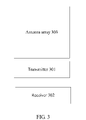
- FIG. 3 is a schematic structural diagram of an antenna system according to an illustrative example.
- the antenna system shown in FIG. 3 is in an active antenna architecture.
- a transmitter 301, a receiver 302, and an antenna array 303 are disposed in an integrated manner, that is, the transmitter 301, the receiver 302, and the antenna array 303 are integrated together to constitute an active antenna.
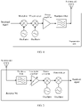
- FIG. 4 is a schematic structural diagram of a transmitter according to an illustrative example.
- the transmitter 401 in this illustrative example is configured to transmit uplink data. Specifically, a modulator included in the transmitter 401 modulates a baseband signal onto a carrier, shifts a modulated bandpass signal to a required operating frequency band by using an up-converter, amplifies a shifted bandpass signal by using a power amplifier, filters an amplified signal, and then sends a filtered signal.
- a modulator included in the transmitter 401 modulates a baseband signal onto a carrier, shifts a modulated bandpass signal to a required operating frequency band by using an up-converter, amplifies a shifted bandpass signal by using a power amplifier, filters an amplified signal, and then sends a filtered signal.
- FIG. 5 is a schematic structural diagram of a receiver according to an illustrative example.
- an RF portion of the receiver 501 is opposite to that of a transmitter:
- a bandpass filter selects a wanted signal from a plurality of radio wave signals;
- a low noise amplifier (LNA) amplifies the selected wanted signal;
- a down-converter converts the RF signal into an IF signal; and
- a demodulator performs demodulation to convert the frequency band signal into a baseband signal.
- LNA low noise amplifier
- the following describes a specific structure of the antenna system, in which isolation between the receiver and the transmitter can be increased and an intermodulation indicator of an antenna array can be improved.
- FIG. 6 is a schematic structural diagram of an antenna system according to an illustrative example.
- the antenna system in this illustrative example includes a receiver set 601, and the receiver set 601 includes a plurality of receivers.
- a quantity of receivers included in the receiver set 601 is not limited in this illustrative example.
- the antenna system further includes a transmitter set 602, and the transmitter set 602 includes a plurality of transmitters.
- a quantity of transmitters included in the transmitter set 602 is not limited in this illustrative example.
- the antenna system further includes an antenna array 603.
- the antenna array 603 in this illustrative example includes a first antenna unit set 604 and a second antenna unit set 605.
- the first antenna unit set 604 includes at least one first target antenna unit 606, and the second antenna unit set 605 includes at least one second target antenna unit 607.
- a specific quantity of first target antenna units 606 included in the first antenna unit set 604 is not limited in this illustrative example. As shown in FIG. 6 , an example in which there are two first target antenna units 606 is used for description in this illustrative example.
- the plurality of first target antenna units 606 are adjacently arranged in the antenna array 603.
- a specific quantity of second target antenna units 607 included in the second antenna unit set 605 is not limited in this illustrative example. As shown in FIG. 6 , an example in which there are four second target antenna units 607 is used for description in this illustrative example.
- the plurality of second target antenna units 607 are adjacently arranged in the antenna array 603.
- the first target antenna unit 606 and the second target antenna unit 607 are different antenna units.
- the first target antenna unit 606 is connected to any receiver 608 in the transmitter set 602, and different first target antenna units 606 are connected to different receivers 608.
- the first target antenna unit 606 in this illustrative example is connected to the receiver 608 by using a duplexer 609.
- the second target antenna unit 607 is connected to any transmitter 610 in the transmitter set 602, and different second target antenna units 607 are connected to different transmitters 610.
- the second target antenna unit 607 in this illustrative example is connected to the transmitter 610 by using a duplexer 609.
- each antenna unit in this illustrative example includes two antenna elements: a first antenna element and a second antenna element.
- a first antenna element As shown in the figure, an example in which the first antenna element is perpendicular to the second antenna element is used for description in this illustrative example, but no limitation is imposed.
- a single polarization antenna or a structure including an element in another form may alternatively be used.
- the antenna array can be divided, so that the first antenna unit set and the second antenna unit set that are obtained through division are antenna units isolated from each other.
- the first target antenna unit included in the first antenna unit set is connected only to the receiver, that is, there is no connection relationship between the first target antenna unit and the transmitter; and the second target antenna unit included in the second antenna unit set is connected only to the transmitter, that is, there is no connection relationship between the second target antenna unit and the receiver.
- the receiver and the transmitter are completely isolated from each other, thereby increasing isolation between the receiver and the transmitter, and effectively improving an intermodulation indicator of the antenna system.
- a relationship between the quantity of receivers and the quantity of transmitters is not limited, that is, the quantities of receivers and transmitters do not need to be the same, so that the antenna system in this illustrative example can be applied to different application scenarios; and each antenna unit in the antenna system needs to be connected to only one receiver or transmitter, different from a case in the prior art in which one antenna unit needs to be connected to both a transmitter and a receiver. It can be learned that a structure of the antenna unit can be simplified in this illustrative example, thereby effectively increasing a yield rate of manufacturing the antenna unit, reducing a consumable, a size, and a weight of the antenna, and facilitating installation and use by a user.
- FIG. 7 is a schematic structural diagram of an antenna system according to another illustrative example.
- first target antenna unit 701 in this illustrative example and a connection relationship of the first target antenna unit 701 refer to the specific description of the first target antenna unit 606 in the illustrative example shown in FIG 6 . Details are not repeated in this illustrative example.
- second target antenna unit 702 in this illustrative example and a connection relationship of the second target antenna unit 702 refer to the specific description of the second target antenna unit 607 in the illustrative example shown in FIG. 6 . Details are not repeated in this illustrative example.
- first target antenna units 701 and five second target antenna units 702 An example in which there are two first target antenna units 701 and five second target antenna units 702 is used for description in this illustrative example. It should be noted that a description of quantities of first target antenna units 701 and second target antenna units 702 in this illustrative example is an optional example. No limitation is imposed.
- the first target antenna unit set includes a plurality of first target antenna units 701
- at least one second target antenna unit 702 is arranged between any two adjacent first target antenna units of the plurality of first target antenna units 701 in an antenna array.
- one or more second target antenna units 702 are arranged between any two adjacent first target antenna units 701.
- one second target antenna unit 702 is arranged between two first target antenna units 701.
- a quantity of second target antenna units 702 arranged between two first target antenna units 701 is not limited in this illustrative example.
- the first target antenna unit 701 and the second target antenna unit 702 may be arranged adjacently. It should be noted that, in this illustrative example, a description of locations of the first target antenna unit 701 and the second target antenna unit 702 in the antenna array is an optional example, and no limitation is imposed provided that: the first target antenna unit 701 is connected only to the receiver 703, and there is no connection relationship between the first target antenna unit 701 and the transmitter 704; and the second target antenna unit 702 is connected only to the transmitter 704, and there is no connection relationship between the second target antenna unit 702 and the receiver 703.
- FIG. 8 is a schematic structural diagram of an antenna system according to another illustrative example.
- a transmitter set 802 in this illustrative example refers to the specific description of the transmitter set 602 shown in FIG. 6 . Details are not repeated in this illustrative example.
- first antenna unit set 803 For a specific description of a first antenna unit set 803 in this illustrative example, refer to the specific description of the first antenna unit set 604 shown in FIG. 6 . Details are not repeated in this illustrative example.
- the antenna system in this illustrative example further includes at least two target device sets.
- a specific quantity of target device sets is not limited in this illustrative example.
- FIG. 8 an example in which there are two target device sets is used for description.
- the antenna system in this illustrative example includes a target device set 8051 and a target device set 8052.
- the target device set 8051 and the target device set 8052 in this illustrative example are in a same structure.
- the target device set 8051 is used as an example.
- the target device set 8051 includes a receiver 806 and a transmitter 807.
- An antenna array in this illustrative example further includes a third antenna unit set 808.
- the third antenna unit set 808 in this illustrative example includes at least one third target antenna unit 809. Specifically, a specific quantity of third target antenna units 809 included in the third antenna unit set 808 is not limited in this illustrative example. As shown in FIG. 8 , an example in which the third antenna unit set 808 in this illustrative example includes one third target antenna unit 809 is used for description.
- the third target antenna unit 809 in this illustrative example includes a first antenna element 810 and a second antenna element 811.
- the first antenna element 810 is connected to both the receiver 806 and the transmitter 807 that are included in the target device set 8051; and the second antenna element 811 is connected to both the receiver 806 and the transmitter 807 that are included in the target device set 8052.
- a specific location of the third antenna unit set 808 is not limited in this illustrative example.
- the third antenna unit set 808 in this illustrative example is arranged between the first antenna unit set 803 and the second antenna unit set 804 in the antenna array.
- the antenna array in this illustrative example includes the first antenna unit set, the second antenna unit set, and the third antenna unit set; the first target antenna unit included in the first antenna unit set is connected only to the receiver, and the second target antenna unit included in the second antenna unit set is connected only to the transmitter; and the third target antenna unit included in the third antenna unit set provided in this illustrative example is connected to both the receiver and the transmitter, and the third antenna unit set is arranged between the first antenna unit set and the second antenna unit set.
- some of the transmitters and the receivers can be isolated from each other, that is, the receiver connected to the first antenna unit set and the transmitter connected to the second antenna unit set can be effectively isolated from each other, thereby increasing isolation between the receiver and the transmitter, and effectively improving an intermodulation indicator of the antenna system.
- a relationship between a quantity of receivers and a quantity of transmitters is not limited, that is, the quantities of receivers and transmitters do not need to be the same, so that the antenna system in this illustrative example can be applied to different application scenarios.
- a structure of the antenna unit can be simplified in this illustrative example, thereby effectively increasing a yield rate of manufacturing the antenna unit, reducing a consumable, a size, and a weight of the antenna, and facilitating installation and use by a user.
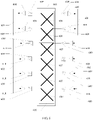
- FIG. 9 is a schematic structural diagram of an antenna system according to an embodiment of the present invention.
- first antenna unit set 903 For a specific description of a first antenna unit set 903 in this embodiment, refer to the specific description of the first antenna unit set 604 shown in FIG. 6 . Details are not repeated in this embodiment.
- an antenna array in this embodiment further includes a fourth antenna unit set 905, and the fourth antenna unit set 905 includes at least one fourth target antenna unit.
- fourth target antenna units included in the fourth antenna unit set 905 is not limited in this embodiment. As shown in FIG. 9 , an example in which the fourth antenna unit set 905 in this embodiment includes two fourth target antenna units 906 is used for description.
- each fourth target antenna unit 906 in this embodiment includes a first antenna element 907 and a second antenna element 908.
- the first antenna element 907 is connected to one receiver in the receiver set 901, and different first antenna elements 907 are connected to different receivers in the receiver set 901; and the second antenna element 908 is connected to one transmitter in the transmitter set 902, and different second antenna elements 908 are connected to different transmitters in the transmitter set 902.
- first antenna element 907 and the second antenna element 908 in this embodiment are corresponding to different polarizations.
- the polarizations corresponding to the first antenna element 907 and the second antenna element 908 are not limited in this embodiment, provided that the first antenna element 907 and the second antenna element 908 are corresponding to different polarizations.
- An example in which the first antenna element 907 is polarized at +45 degrees and the second antenna element 908 is polarized at -45 degrees is used for description in this embodiment.
- the fourth antenna unit set 905 includes a plurality of fourth target antenna units 906, as shown in FIG. 9 , the plurality of fourth target antenna units 906 are arranged adjacently in the antenna array.
- At least one target antenna unit is arranged between any two adjacent fourth target antenna units 906 of the plurality of fourth target antenna units 906 in the antenna array, where the target antenna unit is a first target antenna unit and/or a second target antenna unit.
- the antenna unit can be further divided, so that the fourth target antenna unit 906 includes the first antenna element 907 and the second antenna element 908, and a device connected to the first antenna element 907 is different from a device connected to the second antenna element 908, that is, the first antenna element 907 is connected only to the receiver, and the second antenna element 908 is connected only to the transmitter.
- the receiver and the transmitter can be corresponding to different polarizations.
- the receiver and the transmitter are corresponding to different polarizations of the fourth target antenna unit 906, so that the antenna system in this embodiment can be flexibly configured based on a polarization mode of the antenna unit. In this way, isolation between the receiver and the transmitter is increased, and an intermodulation indicator of the antenna system can be significantly improved.
- a relationship between a quantity of receivers and a quantity of transmitters is not limited, that is, the quantities of receivers and transmitters do not need to be the same, so that the antenna system in this embodiment can be applied to different application scenarios.
- a structure of the antenna unit can be simplified in this embodiment, thereby effectively increasing a yield rate of manufacturing the antenna unit, reducing a consumable, a size, and a weight of the antenna, and facilitating installation and use by a user.
- FIG. 10 is a schematic structural diagram of an antenna system according to another illustrative example.
- the antenna system in this illustrative example includes a plurality of receivers 1001, a plurality of transmitters 1002, and an antenna array 1003.
- the antenna array 1003 in this embodiment includes at least one antenna unit 1004.
- a specific quantity of antenna units 1004 included in the antenna array 1003 is not limited in this illustrative example. As shown in FIG. 10 , an example in which the antenna array 1003 includes four antenna units 1004 is used for description in this illustrative example.
- the antenna unit 1004 includes a first antenna element 1005 and a second antenna element 1006.
- the first antenna element 1005 is connected to the receiver 1001, and different first antenna elements 1005 are connected to different receivers 1001; and the second antenna element 1006 is connected to the transmitter 1002, and different second antenna elements 1006 are connected to different transmitters 1002.
- first antenna element 1005 and the second antenna element 1006 in this illustrative example are corresponding to different polarizations.
- the polarizations corresponding to the first antenna element 1005 and the second antenna element 1006 are not limited in this illustrative example, provided that the first antenna element 1005 and the second antenna element 1006 are corresponding to different polarizations.
- An example in which the first antenna element 1005 is polarized at +45 degrees and the second antenna element 1006 is polarized at -45 degrees is used for description in this illustrative example.
- the antenna unit can be further divided, so that the antenna unit includes the first antenna element and the second antenna element, and a device connected to the first antenna element is different from a device connected to the second antenna element, that is, the first antenna element is connected only to the receiver, and the second antenna element is connected only to the transmitter.
- the receiver and the transmitter can be corresponding to different polarizations.
- the receiver and the transmitter are corresponding to different polarizations of the antenna unit, so that the antenna system in this illustrative example can be flexibly configured based on a polarization mode of the antenna unit. In this way, isolation between the receiver and the transmitter is increased, and an intermodulation indicator of the antenna system can be significantly improved.
- a relationship between a quantity of receivers and a quantity of transmitters is not limited, that is, the quantities of receivers and transmitters do not need to be the same, so that the antenna system in this illustrative example can be applied to different application scenarios.
- a structure of the antenna unit can be simplified in this illustrative example, thereby effectively increasing a yield rate of manufacturing the antenna unit, reducing a consumable, a size, and a weight of the antenna, and facilitating installation and use by a user.
Landscapes
- Engineering & Computer Science (AREA)
- Computer Networks & Wireless Communication (AREA)
- Signal Processing (AREA)
- Physics & Mathematics (AREA)
- Electromagnetism (AREA)
- Variable-Direction Aerials And Aerial Arrays (AREA)
- Details Of Aerials (AREA)
- Support Of Aerials (AREA)
Description
- The present invention relates to the field of communications technologies, and in particular, to an antenna system.
- With development of a wireless communications technology, to increase a system capacity, a multiple-input multiple-output (Multiple Input Multiple Output, MIMO) technology is proposed, and a multi-column antenna is required. The MIMO technology can transmit a plurality of spatial flows through space division multiplexing to increase a capacity of a communications system, and the MIMO technology can improve reliability of the communications system through diversity. With an increase of a quantity of antennas, the MIMO technology increases a significant capacity, but also brings huge challenges to a performance indicator PIM, a consumable, a size, a weight, costs, and a yield rate in antenna design.
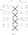
- In an existing solution, as shown in
FIG. 1 , to satisfy the requirement for the multi-column antenna, anantenna array 100 includes a plurality ofantenna units 101, and theantenna unit 101 is connected to both areceiver 103 and a transmitter 104 by using aduplexer 102. - If the existing solution is used, when a quantity of antennas units increases, a consumable, a size, a weight, costs, and the like of the
antenna unit 101 greatly increase, and a yield rate decreases. In addition, isolation between thereceiver 103 and the transmitter 104 is not enough, and consequently intermodulation occurs, and a radio frequency indicator decreases or cannot even be used. TheUS 2013 / 222201 A1 refers to an active antenna system (AAS) radio frequency (RS) module with heat sink integrated antenna reflector. TheUS 2016 / 0172757 A1 refers to a wideband antenna array. TheUS 2003 / 0073463 A1 refers to an active antenna array configuration and control for cellular communication systems. TheWO 2015 / 172292 A1 refers to an antenna system. TheUS 6 006 072 A refers to a method and apparatus for interference cancellation. - Embodiments of the present invention provide an antenna system in which an intermodulation indicator of the antenna system can be improved. The present application is defined in the appended independent claim. Further implementations are disclosed in the dependent claims. In the following, implementations not falling within the scope of the claims are to be understood as examples useful for understanding the application.
-
-
FIG. 1 is a schematic structural diagram of an antenna system provided in the prior art; -
FIG. 2 is a schematic structural diagram of an antenna system according to an illustrative example not falling under the scope of the appended claims; -
FIG. 3 is a schematic structural diagram of an antenna system according to an illustrative example not falling under the scope of the appended claims; -
FIG. 4 is a schematic structural diagram of a transmitter according to an illustrative example not falling under the scope of the appended claims; -
FIG. 5 is a schematic structural diagram of a receiver according to an illustrative example not falling under the scope of the appended claims; -
FIG. 6 is a schematic structural diagram of an antenna system according to an illustrative example not falling under the scope of the appended claims; -
FIG. 7 is a schematic structural diagram of an antenna system according to another illustrative example not falling under the scope of the appended claims; -
FIG. 8 is a schematic structural diagram of an antenna system according to another illustrative example not falling under the scope of the appended claims; -
FIG. 9 is a schematic structural diagram of an antenna system according to another embodiment of the present invention; and -
FIG. 10 is a schematic structural diagram of an antenna system according to another illustrative example not falling under the scope of the appended claims. - The present invention provides an antenna system in which isolation between a receiver and a transmitter can be effectively increased. The following first describes in detail a structure of the antenna system provided in the embodiments from a perspective of a physical device.
- The antenna system may have two structures
- One structure of the antenna system is shown in
FIG. 2. FIG. 2 is a schematic structural diagram of an antenna system according to an illustrative example. - The antenna system shown in
FIG. 2 is in a passive antenna architecture, and the antenna system includes an RRU (English full name: Radio Remote Unit) 200. A transmitter and a receiver are disposed in the RRU 200, and the RRU 200 is connected to an antenna array 201 through acable 202. - The antenna array 201 in this illustrative example includes a plurality of antenna units.
- Specifically, the antenna system shown in
FIG. 2 is usually applied in the following manners: In a manner, the RRU 200 is disposed below a signal tower, the antenna array 201 is disposed above the signal tower, and the RRU 200 is connected to the antenna array 201 through thecable 202. In another manner, the RRU 200 is disposed above the tower, and the RRU 200 is quite close to the antenna array 201. For example, the RRU 200 is disposed below or behind the antenna array 201, and the RRU 200 is connected to the antenna array 201 through thecable 202. - For another manner of configuring a structure of the antenna system, refer to
FIG. 3. FIG. 3 is a schematic structural diagram of an antenna system according to an illustrative example. - The antenna system shown in
FIG. 3 is in an active antenna architecture. In a structure shown inFIG. 3 , atransmitter 301, areceiver 302, and anantenna array 303 are disposed in an integrated manner, that is, thetransmitter 301, thereceiver 302, and theantenna array 303 are integrated together to constitute an active antenna. - The following describes a specific structure of a transmitter from a perspective of a physical device with reference to
FIG. 4. FIG. 4 is a schematic structural diagram of a transmitter according to an illustrative example. - It should be noted that a description of the specific structure of the transmitter in this embodiment is an optional example. No limitation is imposed.
- The
transmitter 401 in this illustrative example is configured to transmit uplink data. Specifically, a modulator included in thetransmitter 401 modulates a baseband signal onto a carrier, shifts a modulated bandpass signal to a required operating frequency band by using an up-converter, amplifies a shifted bandpass signal by using a power amplifier, filters an amplified signal, and then sends a filtered signal. - The following describes a specific structure of a receiver from a perspective of a physical device with reference to
FIG. 5. FIG. 5 is a schematic structural diagram of a receiver according to an illustrative example. - It should be noted that a description of the specific structure of the receiver in this illustrative example is an optional example. No limitation is imposed.
- In the
receiver 501 in this illustrative example, an RF portion of thereceiver 501 is opposite to that of a transmitter: A bandpass filter selects a wanted signal from a plurality of radio wave signals; a low noise amplifier (LNA) amplifies the selected wanted signal; a down-converter converts the RF signal into an IF signal; and a demodulator performs demodulation to convert the frequency band signal into a baseband signal. - Based on the foregoing description of the physical structure of the antenna system and with reference to the accompanying drawings, the following describes a specific structure of the antenna system, in which isolation between the receiver and the transmitter can be increased and an intermodulation indicator of an antenna array can be improved.
-
FIG. 6 is a schematic structural diagram of an antenna system according to an illustrative example. - The antenna system in this illustrative example includes a
receiver set 601, and thereceiver set 601 includes a plurality of receivers. A quantity of receivers included in thereceiver set 601 is not limited in this illustrative example. For a description of a specific structure of the receiver, refer to the foregoing illustrative example. Details are not repeated in this illustrative example. - The antenna system further includes a
transmitter set 602, and thetransmitter set 602 includes a plurality of transmitters. A quantity of transmitters included in thetransmitter set 602 is not limited in this illustrative example. For a description of a specific structure of the transmitter, refer to the foregoing illustrative example. Details are not repeated in this illustrative example. - The antenna system further includes an
antenna array 603. - Specifically, the
antenna array 603 in this illustrative example includes a first antenna unit set 604 and a second antenna unit set 605. - More specifically, the first antenna unit set 604 includes at least one first
target antenna unit 606, and the second antenna unit set 605 includes at least one secondtarget antenna unit 607. - A specific quantity of first
target antenna units 606 included in the first antenna unit set 604 is not limited in this illustrative example. As shown inFIG. 6 , an example in which there are two firsttarget antenna units 606 is used for description in this illustrative example. - In this illustrative example, as shown in
FIG. 6 , the plurality of firsttarget antenna units 606 are adjacently arranged in theantenna array 603. - A specific quantity of second
target antenna units 607 included in the second antenna unit set 605 is not limited in this illustrative example. As shown inFIG. 6 , an example in which there are four secondtarget antenna units 607 is used for description in this illustrative example. - In this illustrative example, as shown in
FIG. 6 , the plurality of secondtarget antenna units 607 are adjacently arranged in theantenna array 603. - The first
target antenna unit 606 and the secondtarget antenna unit 607 are different antenna units. - In this illustrative example, the first
target antenna unit 606 is connected to anyreceiver 608 in the transmitter set 602, and different firsttarget antenna units 606 are connected todifferent receivers 608. - Specifically, the first
target antenna unit 606 in this illustrative example is connected to thereceiver 608 by using aduplexer 609. - In this illustrative example, the second
target antenna unit 607 is connected to anytransmitter 610 in the transmitter set 602, and different secondtarget antenna units 607 are connected todifferent transmitters 610. - Specifically, the second
target antenna unit 607 in this illustrative example is connected to thetransmitter 610 by using aduplexer 609. - More specifically, each antenna unit in this illustrative example includes two antenna elements: a first antenna element and a second antenna element. As shown in the figure, an example in which the first antenna element is perpendicular to the second antenna element is used for description in this illustrative example, but no limitation is imposed. In specific application, a single polarization antenna or a structure including an element in another form may alternatively be used.
- Beneficial effects of using the antenna system in this illustrative example are as follows.
- In the antenna system in this illustrative example, the antenna array can be divided, so that the first antenna unit set and the second antenna unit set that are obtained through division are antenna units isolated from each other. To be specific, the first target antenna unit included in the first antenna unit set is connected only to the receiver, that is, there is no connection relationship between the first target antenna unit and the transmitter; and the second target antenna unit included in the second antenna unit set is connected only to the transmitter, that is, there is no connection relationship between the second target antenna unit and the receiver. In this way, in the antenna system in this illustrative example, the receiver and the transmitter are completely isolated from each other, thereby increasing isolation between the receiver and the transmitter, and effectively improving an intermodulation indicator of the antenna system.
- For the antenna system used in this illustrative example, a relationship between the quantity of receivers and the quantity of transmitters is not limited, that is, the quantities of receivers and transmitters do not need to be the same, so that the antenna system in this illustrative example can be applied to different application scenarios; and each antenna unit in the antenna system needs to be connected to only one receiver or transmitter, different from a case in the prior art in which one antenna unit needs to be connected to both a transmitter and a receiver. It can be learned that a structure of the antenna unit can be simplified in this illustrative example, thereby effectively increasing a yield rate of manufacturing the antenna unit, reducing a consumable, a size, and a weight of the antenna, and facilitating installation and use by a user.
- For another structure of the antenna system in the illustrative examples, refer to
FIG 7. FIG. 7 is a schematic structural diagram of an antenna system according to another illustrative example. - In the illustrative example shown in
FIG. 7 , for a specific description of a receiver set and a transmitter set, refer to the foregoing illustrative example. Details are not repeated in this illustrative example. - For a specific description of a first
target antenna unit 701 in this illustrative example and a connection relationship of the firsttarget antenna unit 701, refer to the specific description of the firsttarget antenna unit 606 in the illustrative example shown inFIG 6 . Details are not repeated in this illustrative example. For a specific description of a secondtarget antenna unit 702 in this illustrative example and a connection relationship of the secondtarget antenna unit 702, refer to the specific description of the secondtarget antenna unit 607 in the illustrative example shown inFIG. 6 . Details are not repeated in this illustrative example. - An example in which there are two first
target antenna units 701 and five secondtarget antenna units 702 is used for description in this illustrative example. It should be noted that a description of quantities of firsttarget antenna units 701 and secondtarget antenna units 702 in this illustrative example is an optional example. No limitation is imposed. - Specifically, in this illustrative example, for example, if the first target antenna unit set includes a plurality of first
target antenna units 701, at least one secondtarget antenna unit 702 is arranged between any two adjacent first target antenna units of the plurality of firsttarget antenna units 701 in an antenna array. - In this illustrative example, one or more second
target antenna units 702 are arranged between any two adjacent firsttarget antenna units 701. For example, as shown inFIG. 7 , one secondtarget antenna unit 702 is arranged between two firsttarget antenna units 701. It should be noted that a quantity of secondtarget antenna units 702 arranged between two firsttarget antenna units 701 is not limited in this illustrative example. - For the antenna system used in this illustrative example, in the antenna array, the first
target antenna unit 701 and the secondtarget antenna unit 702 may be arranged adjacently. It should be noted that, in this illustrative example, a description of locations of the firsttarget antenna unit 701 and the secondtarget antenna unit 702 in the antenna array is an optional example, and no limitation is imposed provided that: the firsttarget antenna unit 701 is connected only to thereceiver 703, and there is no connection relationship between the firsttarget antenna unit 701 and thetransmitter 704; and the secondtarget antenna unit 702 is connected only to thetransmitter 704, and there is no connection relationship between the secondtarget antenna unit 702 and thereceiver 703. - For beneficial effects brought by the antenna system shown in
FIG. 7 , refer to the illustrative example shown inFIG. 6 . Details are not repeated in this illustrative example. - For another structure of the antenna system in the illustrative example, refer to
FIG 8. FIG. 8 is a schematic structural diagram of an antenna system according to another illustrative example. - In the illustrative example shown in
FIG. 8 , for a specific description of areceiver set 801, refer to the specific description of the receiver set 601 shown inFIG. 6 . Details are not repeated in this illustrative example. - For a specific description of a
transmitter set 802 in this illustrative example, refer to the specific description of the transmitter set 602 shown inFIG. 6 . Details are not repeated in this illustrative example. - For a specific description of a first antenna unit set 803 in this illustrative example, refer to the specific description of the first antenna unit set 604 shown in
FIG. 6 . Details are not repeated in this illustrative example. - For a specific description of a second antenna unit set 804 in this illustrative example, refer to the specific description of the second antenna unit set 605 shown in
FIG. 6 . Details are not repeated in this illustrative example. - Compared with the antenna system shown in
FIG. 6 , the antenna system in this illustrative example further includes at least two target device sets. A specific quantity of target device sets is not limited in this illustrative example. As shown inFIG. 8 , an example in which there are two target device sets is used for description. To be specific, the antenna system in this illustrative example includes atarget device set 8051 and atarget device set 8052. - The
target device set 8051 and the target device set 8052 in this illustrative example are in a same structure. Thetarget device set 8051 is used as an example. Thetarget device set 8051 includes areceiver 806 and atransmitter 807. For a description of specific structures of thereceiver 806 and thetransmitter 807, refer to the foregoing illustrative example. Details are not repeated in this illustrative example. - An antenna array in this illustrative example further includes a third antenna unit set 808.
- The third antenna unit set 808 in this illustrative example includes at least one third
target antenna unit 809. Specifically, a specific quantity of thirdtarget antenna units 809 included in the third antenna unit set 808 is not limited in this illustrative example. As shown inFIG. 8 , an example in which the third antenna unit set 808 in this illustrative example includes one thirdtarget antenna unit 809 is used for description. - Specifically, the third
target antenna unit 809 in this illustrative example includes afirst antenna element 810 and asecond antenna element 811. - More specifically, the
first antenna element 810 is connected to both thereceiver 806 and thetransmitter 807 that are included in thetarget device set 8051; and
thesecond antenna element 811 is connected to both thereceiver 806 and thetransmitter 807 that are included in thetarget device set 8052. - A specific location of the third antenna unit set 808 is not limited in this illustrative example. Optionally, the third antenna unit set 808 in this illustrative example is arranged between the first antenna unit set 803 and the second antenna unit set 804 in the antenna array.
- For the antenna system used in this illustrative example, it can be learned that the antenna array in this illustrative example includes the first antenna unit set, the second antenna unit set, and the third antenna unit set; the first target antenna unit included in the first antenna unit set is connected only to the receiver, and the second target antenna unit included in the second antenna unit set is connected only to the transmitter; and the third target antenna unit included in the third antenna unit set provided in this illustrative example is connected to both the receiver and the transmitter, and the third antenna unit set is arranged between the first antenna unit set and the second antenna unit set. It can be learned that, for the antenna system used in this illustrative example, some of the transmitters and the receivers can be isolated from each other, that is, the receiver connected to the first antenna unit set and the transmitter connected to the second antenna unit set can be effectively isolated from each other, thereby increasing isolation between the receiver and the transmitter, and effectively improving an intermodulation indicator of the antenna system.
- For the antenna system used in this illustrative example, a relationship between a quantity of receivers and a quantity of transmitters is not limited, that is, the quantities of receivers and transmitters do not need to be the same, so that the antenna system in this illustrative example can be applied to different application scenarios. In addition, a structure of the antenna unit can be simplified in this illustrative example, thereby effectively increasing a yield rate of manufacturing the antenna unit, reducing a consumable, a size, and a weight of the antenna, and facilitating installation and use by a user.
- For an embodiment of the antenna system, refer to
FIG. 9. FIG. 9 is a schematic structural diagram of an antenna system according to an embodiment of the present invention. - In the embodiment shown in
FIG. 9 , for a specific description of areceiver set 901, refer to the specific description of the receiver set 601 shown inFIG. 6 . Details are not repeated in this embodiment. - For a specific description of a
transmitter set 902 in this embodiment, refer to the specific description of the transmitter set 602 shown inFIG. 6 . Details are not repeated in this embodiment. - For a specific description of a first antenna unit set 903 in this embodiment, refer to the specific description of the first antenna unit set 604 shown in
FIG. 6 . Details are not repeated in this embodiment. - For a specific description of a second antenna unit set 904 in this embodiment, refer to the specific description of the second antenna unit set 605 shown in
FIG. 6 . Details are not repeated in this embodiment. - As shown in
FIG. 9 , an antenna array in this embodiment further includes a fourth antenna unit set 905, and the fourth antenna unit set 905 includes at least one fourth target antenna unit. - It should be noted that a specific quantity of fourth target antenna units included in the fourth antenna unit set 905 is not limited in this embodiment. As shown in
FIG. 9 , an example in which the fourth antenna unit set 905 in this embodiment includes two fourthtarget antenna units 906 is used for description. - Specifically, each fourth
target antenna unit 906 in this embodiment includes afirst antenna element 907 and asecond antenna element 908. - More specifically, the
first antenna element 907 is connected to one receiver in the receiver set 901, and differentfirst antenna elements 907 are connected to different receivers in the receiver set 901; and
thesecond antenna element 908 is connected to one transmitter in the transmitter set 902, and differentsecond antenna elements 908 are connected to different transmitters in thetransmitter set 902. - It should be noted that the
first antenna element 907 and thesecond antenna element 908 in this embodiment are corresponding to different polarizations. - The polarizations corresponding to the
first antenna element 907 and thesecond antenna element 908 are not limited in this embodiment, provided that thefirst antenna element 907 and thesecond antenna element 908 are corresponding to different polarizations. An example in which thefirst antenna element 907 is polarized at +45 degrees and thesecond antenna element 908 is polarized at -45 degrees is used for description in this embodiment. - Optionally, in this embodiment, for example, if the fourth antenna unit set 905 includes a plurality of fourth
target antenna units 906, as shown inFIG. 9 , the plurality of fourthtarget antenna units 906 are arranged adjacently in the antenna array. - Further optionally, in another embodiment, at least one target antenna unit is arranged between any two adjacent fourth
target antenna units 906 of the plurality of fourthtarget antenna units 906 in the antenna array, where the target antenna unit is a first target antenna unit and/or a second target antenna unit. - For beneficial effects brought by the first target antenna unit and the second target antenna unit in this embodiment, refer to the foregoing embodiment. Details are not repeated in this embodiment. The following describes beneficial effects brought by the fourth
target antenna unit 906 in this embodiment: - In this embodiment, the antenna unit can be further divided, so that the fourth
target antenna unit 906 includes thefirst antenna element 907 and thesecond antenna element 908, and a device connected to thefirst antenna element 907 is different from a device connected to thesecond antenna element 908, that is, thefirst antenna element 907 is connected only to the receiver, and thesecond antenna element 908 is connected only to the transmitter. In this arrangement, the receiver and the transmitter can be corresponding to different polarizations. It can be learned that, for the antenna system used in this embodiment, among a plurality of receivers connected to thefirst antenna element 907 and a plurality of transmitters connected to thesecond antenna element 908, the receiver and the transmitter are corresponding to different polarizations of the fourthtarget antenna unit 906, so that the antenna system in this embodiment can be flexibly configured based on a polarization mode of the antenna unit. In this way, isolation between the receiver and the transmitter is increased, and an intermodulation indicator of the antenna system can be significantly improved. - For the antenna system used in this embodiment, a relationship between a quantity of receivers and a quantity of transmitters is not limited, that is, the quantities of receivers and transmitters do not need to be the same, so that the antenna system in this embodiment can be applied to different application scenarios. In addition, a structure of the antenna unit can be simplified in this embodiment, thereby effectively increasing a yield rate of manufacturing the antenna unit, reducing a consumable, a size, and a weight of the antenna, and facilitating installation and use by a user.
- For another structure of the antenna system in the illustrative examples, refer to
FIG. 10. FIG. 10 is a schematic structural diagram of an antenna system according to another illustrative example. - As shown in
FIG. 10 , the antenna system in this illustrative example includes a plurality ofreceivers 1001, a plurality oftransmitters 1002, and anantenna array 1003. - The
antenna array 1003 in this embodiment includes at least oneantenna unit 1004. - A specific quantity of
antenna units 1004 included in theantenna array 1003 is not limited in this illustrative example. As shown inFIG. 10 , an example in which theantenna array 1003 includes fourantenna units 1004 is used for description in this illustrative example. - The
antenna unit 1004 includes afirst antenna element 1005 and asecond antenna element 1006. - Specifically, the
first antenna element 1005 is connected to thereceiver 1001, and differentfirst antenna elements 1005 are connected todifferent receivers 1001; and
thesecond antenna element 1006 is connected to thetransmitter 1002, and differentsecond antenna elements 1006 are connected todifferent transmitters 1002. - It should be noted that the
first antenna element 1005 and thesecond antenna element 1006 in this illustrative example are corresponding to different polarizations. - The polarizations corresponding to the
first antenna element 1005 and thesecond antenna element 1006 are not limited in this illustrative example, provided that thefirst antenna element 1005 and thesecond antenna element 1006 are corresponding to different polarizations. An example in which thefirst antenna element 1005 is polarized at +45 degrees and thesecond antenna element 1006 is polarized at -45 degrees is used for description in this illustrative example. - In this illustrative example, the antenna unit can be further divided, so that the antenna unit includes the first antenna element and the second antenna element, and a device connected to the first antenna element is different from a device connected to the second antenna element, that is, the first antenna element is connected only to the receiver, and the second antenna element is connected only to the transmitter. In this arrangement, the receiver and the transmitter can be corresponding to different polarizations. It can be learned that, for the antenna system used in this illustrative example, among the plurality of receivers connected to the antenna units and the plurality of transmitters connected to the second antenna elements, the receiver and the transmitter are corresponding to different polarizations of the antenna unit, so that the antenna system in this illustrative example can be flexibly configured based on a polarization mode of the antenna unit. In this way, isolation between the receiver and the transmitter is increased, and an intermodulation indicator of the antenna system can be significantly improved.
- Moreover, for the antenna system used in this illustrative example, a relationship between a quantity of receivers and a quantity of transmitters is not limited, that is, the quantities of receivers and transmitters do not need to be the same, so that the antenna system in this illustrative example can be applied to different application scenarios. In addition, a structure of the antenna unit can be simplified in this illustrative example, thereby effectively increasing a yield rate of manufacturing the antenna unit, reducing a consumable, a size, and a weight of the antenna, and facilitating installation and use by a user.
- The foregoing embodiments are merely intended to describe the technical solutions of the present invention, but not to limit the present invention. Although the present invention is described in detail with reference to the foregoing embodiments, persons of ordinary skill in the art should understand that they may still make modifications to the technical solutions described in the foregoing embodiments or make replacements to some technical features thereof, without departing from the scope of the invention defined in the appended claims.
Claims (6)
- An antenna system, comprising a receiver set (601, 901), a transmitter set (602, 902), and an antenna array (603), wherein the receiver set (601, 901) comprises a plurality of receivers (608), and the transmitter set (602, 902) comprises a plurality of transmitters (610); and the antenna array (603) comprises a first antenna unit set (604, 903) and a second antenna unit set (605, 904); the first antenna unit set (604, 903) comprises at least one first target antenna unit (606), the second antenna unit set (605, 904) comprises at least one second target antenna unit (607), and any one of the at least one first target antenna unit (606) and any one of the at least one second target antenna unit (607) are different antenna units; and any one of the at least one first target antenna unit (606) is only connected to any receiver (608) in the receiver set (601, 901), and any one of the at least one second target antenna unit (607) is only connected to any transmitter (610) in the transmitter set (602, 902), wherein the first antenna unit set (604, 903) comprises a plurality of first target antenna units (606), the plurality of first target antenna units (606) are adjacently arranged in the antenna array (603); wherein the second antenna unit set (605, 904) comprises a plurality of second target antenna units (607), the plurality of second target antenna units (607) are adjacently arranged in the antenna array (603), wherein the antenna array (603) further comprises a fourth antenna unit set (905), the fourth antenna unit set (905) comprises at least one fourth target antenna unit (906), and any one of the at least one fourth target antenna unit (906) comprises a first antenna element (907) and a second antenna element (908); the first antenna element (907) is only connected to any receiver (608) in the receiver set (601, 901), and the second antenna element (908) is only connected to any transmitter (610) in the transmitter set (602, 902) and wherein the first antenna element (907) and the second antenna element (908) are corresponding to different polarizations.
- The antenna system according to claim 1, wherein the first antenna unit set (604, 903) comprises a plurality of first target antenna units (606), at least one second target antenna unit (607) is arranged between any two adjacent first target antenna units (606) of the plurality of first target antenna units (606) in the antenna array (603).
- The antenna system according to claim 1, wherein the fourth antenna unit set (905) is disposed between the first antenna unit set (604, 903) and the second antenna unit set (605, 904) in the antenna array.
- The antenna system according to claim 1, wherein the first antenna element (907) is polarized at +45 degrees, and the second antenna element (908) is polarized at -45 degrees.
- The antenna system according to any one of claims 1 or 4, wherein the fourth antenna unit set (905) comprises a plurality of fourth target antenna units (906), the plurality of fourth target antenna units (906) are adjacently arranged in the antenna array.
- The antenna system according to any one of claims 1 or 4, wherein the fourth antenna unit set (905) comprises a plurality of fourth target antenna units (906), at least one target antenna unit (906) is arranged between any two adjacent fourth target antenna units (906) of the plurality of fourth target antenna units (906) in the antenna array, wherein the target antenna unit (906) is the first target antenna unit and/or the second target antenna unit.
Applications Claiming Priority (2)
| Application Number | Priority Date | Filing Date | Title |
|---|---|---|---|
| CN201611247600.3A CN106848606B (en) | 2016-12-29 | 2016-12-29 | Antenna system |
| PCT/CN2017/118536 WO2018121508A1 (en) | 2016-12-29 | 2017-12-26 | Antenna system |
Publications (3)
| Publication Number | Publication Date |
|---|---|
| EP3553888A1 EP3553888A1 (en) | 2019-10-16 |
| EP3553888A4 EP3553888A4 (en) | 2019-12-18 |
| EP3553888B1 true EP3553888B1 (en) | 2022-08-10 |
Family
ID=59115160
Family Applications (1)
| Application Number | Title | Priority Date | Filing Date |
|---|---|---|---|
| EP17888595.0A Active EP3553888B1 (en) | 2016-12-29 | 2017-12-26 | Antenna system |
Country Status (6)
| Country | Link |
|---|---|
| US (1) | US11012107B2 (en) |
| EP (1) | EP3553888B1 (en) |
| JP (1) | JP2020503779A (en) |
| KR (1) | KR102278198B1 (en) |
| CN (1) | CN106848606B (en) |
| WO (1) | WO2018121508A1 (en) |
Families Citing this family (4)
| Publication number | Priority date | Publication date | Assignee | Title |
|---|---|---|---|---|
| CN106848606B (en) | 2016-12-29 | 2021-01-05 | 上海华为技术有限公司 | Antenna system |
| CN110100468A (en) * | 2017-09-29 | 2019-08-06 | 华为技术有限公司 | Access point apparatus and communication means |
| CN109004373A (en) * | 2018-07-25 | 2018-12-14 | 南京濠暻通讯科技有限公司 | A kind of high integration active integrated antenna module for the 5th third-generation mobile communication |
| US11549034B2 (en) | 2018-08-09 | 2023-01-10 | Versum Materials Us, Llc | Oxide chemical mechanical planarization (CMP) polishing compositions |
Family Cites Families (22)
| Publication number | Priority date | Publication date | Assignee | Title |
|---|---|---|---|---|
| JPH03226690A (en) * | 1990-02-01 | 1991-10-07 | Mitsubishi Electric Corp | Digital beam forming antenna apparatus |
| US5581268A (en) * | 1995-08-03 | 1996-12-03 | Globalstar L.P. | Method and apparatus for increasing antenna efficiency for hand-held mobile satellite communications terminal |
| US6900775B2 (en) * | 1997-03-03 | 2005-05-31 | Celletra Ltd. | Active antenna array configuration and control for cellular communication systems |
| SE510995C2 (en) * | 1997-03-24 | 1999-07-19 | Ericsson Telefon Ab L M | Active broadcast / receive group antenna |
| JP2980053B2 (en) * | 1997-03-28 | 1999-11-22 | 日本電気株式会社 | Interference wave canceller |
| US6760603B1 (en) * | 1997-09-15 | 2004-07-06 | Kathrein-Werke Kg | Compact dual-polarized adaptive antenna array communication method and apparatus |
| US6094178A (en) * | 1997-11-14 | 2000-07-25 | Ericsson, Inc. | Dual mode quadrifilar helix antenna and associated methods of operation |
| US6583763B2 (en) * | 1999-04-26 | 2003-06-24 | Andrew Corporation | Antenna structure and installation |
| US6304214B1 (en) * | 1999-05-07 | 2001-10-16 | Lucent Technologies Inc. | Antenna array system having coherent and noncoherent reception characteristics |
| EP1396047A1 (en) | 2001-05-15 | 2004-03-10 | Nokia Corporation | Data transmission method and arrangement |
| US8416142B2 (en) * | 2009-12-18 | 2013-04-09 | Kathrein-Werke Kg | Dual-polarized group antenna |
| CN102439846B (en) * | 2010-05-06 | 2014-03-12 | 华为技术有限公司 | Method, device and system for polarizing signal |
| US9407008B2 (en) | 2011-06-06 | 2016-08-02 | Poynting Antennas (Proprietary) Limited | Multi-beam multi-radio antenna |
| CN102916259B (en) * | 2011-08-04 | 2015-06-24 | 中国电信股份有限公司 | Multiple-input and multiple-output antenna |
| US9209523B2 (en) * | 2012-02-24 | 2015-12-08 | Futurewei Technologies, Inc. | Apparatus and method for modular multi-sector active antenna system |
| US9244163B2 (en) * | 2012-05-17 | 2016-01-26 | Farrokh Mohamadi | Integrated ultra wideband, wafer scale, RHCP-LHCP arrays |
| CN103713376B (en) | 2012-09-28 | 2017-05-24 | 中强光电股份有限公司 | Projection camera and optical engine |
| DE102013012305A1 (en) * | 2013-07-24 | 2015-01-29 | Kathrein-Werke Kg | Wideband antenna array |
| CN105264938A (en) | 2014-05-12 | 2016-01-20 | 华为技术有限公司 | Antenna system |
| CN106329151B (en) | 2015-06-30 | 2019-10-22 | 华为技术有限公司 | A kind of aerial array and the network equipment |
| CN105471486B (en) * | 2016-01-13 | 2019-03-08 | 深圳市顶一精密五金有限公司 | Radio wave signal synchronization system |
| CN106848606B (en) * | 2016-12-29 | 2021-01-05 | 上海华为技术有限公司 | Antenna system |
-
2016
- 2016-12-29 CN CN201611247600.3A patent/CN106848606B/en active Active
-
2017
- 2017-12-26 KR KR1020197022076A patent/KR102278198B1/en active IP Right Grant
- 2017-12-26 JP JP2019535769A patent/JP2020503779A/en active Pending
- 2017-12-26 WO PCT/CN2017/118536 patent/WO2018121508A1/en unknown
- 2017-12-26 EP EP17888595.0A patent/EP3553888B1/en active Active
-
2019
- 2019-06-27 US US16/455,741 patent/US11012107B2/en active Active
Also Published As
| Publication number | Publication date |
|---|---|
| US20190319652A1 (en) | 2019-10-17 |
| CN106848606A (en) | 2017-06-13 |
| CN106848606B (en) | 2021-01-05 |
| EP3553888A4 (en) | 2019-12-18 |
| JP2020503779A (en) | 2020-01-30 |
| KR20190095484A (en) | 2019-08-14 |
| KR102278198B1 (en) | 2021-07-15 |
| US11012107B2 (en) | 2021-05-18 |
| WO2018121508A1 (en) | 2018-07-05 |
| EP3553888A1 (en) | 2019-10-16 |
Similar Documents
| Publication | Publication Date | Title |
|---|---|---|
| US11012107B2 (en) | Antenna system | |
| US20190372530A1 (en) | Distributed antenna system architectures | |
| EP2919391B1 (en) | Radio frequency channel for carrier aggregation | |
| US9225382B2 (en) | Tunable filter front end architecture for non-contiguous carrier aggregation | |
| US20170279500A1 (en) | Antenna and Active Antenna System | |
| US8842788B2 (en) | Systems and methods for improved high capacity in wireless communication systems | |
| US20130114578A1 (en) | Transmission method and apparatus for carrier aggregation and uplink mimo | |
| JP2009524980A (en) | Method and apparatus for reducing combiner loss in a multi-sector omni base station | |
| CN102761352A (en) | FDD-LTE (Frequency Division Duplexing-Long Term Evolution) indoor coverage system and signal transmission method | |
| CN103368718A (en) | Full-duplex wireless communication device, method and system | |
| WO2012096101A1 (en) | Wireless communication device | |
| CA3042362A1 (en) | Multiple-input multiple-output(mimo) repeater system | |
| KR20230124740A (en) | Radio frequency circuits and electronics | |
| JP6035120B2 (en) | Energy consumption reduction method and wireless communication terminal | |
| CN101938291A (en) | Device for transceiver radio frequency link | |
| US11165165B2 (en) | Antenna system, base station, and communications system | |
| CN204168290U (en) | A kind of multi-mode mine mobile communication system | |
| EP4057517A1 (en) | Antenna transceiver module, multi-input multi-output antenna transceiver system, and base station | |
| EP2512038B1 (en) | Radio communication apparatus | |
| CN106876905A (en) | A kind of double frequency mimo antenna of high-isolation | |
| CN216056991U (en) | Communication equipment sharing hardware channel | |
| EP2803146B1 (en) | Systems and methods for improved high capacity in wireless communication systems | |
| TW202435573A (en) | Circuit structure for multiple antenna radio unit, base station, and satellite communications |
Legal Events
| Date | Code | Title | Description |
|---|---|---|---|
| STAA | Information on the status of an ep patent application or granted ep patent |
Free format text: STATUS: THE INTERNATIONAL PUBLICATION HAS BEEN MADE |
|
| PUAI | Public reference made under article 153(3) epc to a published international application that has entered the european phase |
Free format text: ORIGINAL CODE: 0009012 |
|
| STAA | Information on the status of an ep patent application or granted ep patent |
Free format text: STATUS: REQUEST FOR EXAMINATION WAS MADE |
|
| 17P | Request for examination filed |
Effective date: 20190712 |
|
| AK | Designated contracting states |
Kind code of ref document: A1 Designated state(s): AL AT BE BG CH CY CZ DE DK EE ES FI FR GB GR HR HU IE IS IT LI LT LU LV MC MK MT NL NO PL PT RO RS SE SI SK SM TR |
|
| AX | Request for extension of the european patent |
Extension state: BA ME |
|
| A4 | Supplementary search report drawn up and despatched |
Effective date: 20191120 |
|
| RIC1 | Information provided on ipc code assigned before grant |
Ipc: H01Q 1/24 20060101AFI20191114BHEP Ipc: H01Q 1/52 20060101ALI20191114BHEP Ipc: H01Q 5/42 20150101ALI20191114BHEP Ipc: H01Q 21/24 20060101ALN20191114BHEP |
|
| DAV | Request for validation of the european patent (deleted) | ||
| DAX | Request for extension of the european patent (deleted) | ||
| STAA | Information on the status of an ep patent application or granted ep patent |
Free format text: STATUS: EXAMINATION IS IN PROGRESS |
|
| 17Q | First examination report despatched |
Effective date: 20201029 |
|
| STAA | Information on the status of an ep patent application or granted ep patent |
Free format text: STATUS: EXAMINATION IS IN PROGRESS |
|
| REG | Reference to a national code |
Ref country code: DE Ref legal event code: R079 Ref document number: 602017060618 Country of ref document: DE Free format text: PREVIOUS MAIN CLASS: H01Q0023000000 Ipc: H01Q0001240000 |
|
| GRAP | Despatch of communication of intention to grant a patent |
Free format text: ORIGINAL CODE: EPIDOSNIGR1 |
|
| STAA | Information on the status of an ep patent application or granted ep patent |
Free format text: STATUS: GRANT OF PATENT IS INTENDED |
|
| RIC1 | Information provided on ipc code assigned before grant |
Ipc: H01Q 21/28 20060101ALI20220217BHEP Ipc: H01Q 21/24 20060101ALI20220217BHEP Ipc: H01Q 21/08 20060101ALI20220217BHEP Ipc: H01Q 1/52 20060101ALI20220217BHEP Ipc: H01Q 1/24 20060101AFI20220217BHEP |
|
| INTG | Intention to grant announced |
Effective date: 20220317 |
|
| GRAS | Grant fee paid |
Free format text: ORIGINAL CODE: EPIDOSNIGR3 |
|
| GRAA | (expected) grant |
Free format text: ORIGINAL CODE: 0009210 |
|
| STAA | Information on the status of an ep patent application or granted ep patent |
Free format text: STATUS: THE PATENT HAS BEEN GRANTED |
|
| AK | Designated contracting states |
Kind code of ref document: B1 Designated state(s): AL AT BE BG CH CY CZ DE DK EE ES FI FR GB GR HR HU IE IS IT LI LT LU LV MC MK MT NL NO PL PT RO RS SE SI SK SM TR |
|
| REG | Reference to a national code |
Ref country code: AT Ref legal event code: REF Ref document number: 1511234 Country of ref document: AT Kind code of ref document: T Effective date: 20220815 Ref country code: CH Ref legal event code: EP |
|
| REG | Reference to a national code |
Ref country code: DE Ref legal event code: R096 Ref document number: 602017060618 Country of ref document: DE |
|
| REG | Reference to a national code |
Ref country code: IE Ref legal event code: FG4D |
|
| REG | Reference to a national code |
Ref country code: NL Ref legal event code: MP Effective date: 20220810 |
|
| REG | Reference to a national code |
Ref country code: LT Ref legal event code: MG9D |
|
| PG25 | Lapsed in a contracting state [announced via postgrant information from national office to epo] |
Ref country code: SE Free format text: LAPSE BECAUSE OF FAILURE TO SUBMIT A TRANSLATION OF THE DESCRIPTION OR TO PAY THE FEE WITHIN THE PRESCRIBED TIME-LIMIT Effective date: 20220810 Ref country code: RS Free format text: LAPSE BECAUSE OF FAILURE TO SUBMIT A TRANSLATION OF THE DESCRIPTION OR TO PAY THE FEE WITHIN THE PRESCRIBED TIME-LIMIT Effective date: 20220810 Ref country code: PT Free format text: LAPSE BECAUSE OF FAILURE TO SUBMIT A TRANSLATION OF THE DESCRIPTION OR TO PAY THE FEE WITHIN THE PRESCRIBED TIME-LIMIT Effective date: 20221212 Ref country code: NO Free format text: LAPSE BECAUSE OF FAILURE TO SUBMIT A TRANSLATION OF THE DESCRIPTION OR TO PAY THE FEE WITHIN THE PRESCRIBED TIME-LIMIT Effective date: 20221110 Ref country code: NL Free format text: LAPSE BECAUSE OF FAILURE TO SUBMIT A TRANSLATION OF THE DESCRIPTION OR TO PAY THE FEE WITHIN THE PRESCRIBED TIME-LIMIT Effective date: 20220810 Ref country code: LV Free format text: LAPSE BECAUSE OF FAILURE TO SUBMIT A TRANSLATION OF THE DESCRIPTION OR TO PAY THE FEE WITHIN THE PRESCRIBED TIME-LIMIT Effective date: 20220810 Ref country code: LT Free format text: LAPSE BECAUSE OF FAILURE TO SUBMIT A TRANSLATION OF THE DESCRIPTION OR TO PAY THE FEE WITHIN THE PRESCRIBED TIME-LIMIT Effective date: 20220810 Ref country code: FI Free format text: LAPSE BECAUSE OF FAILURE TO SUBMIT A TRANSLATION OF THE DESCRIPTION OR TO PAY THE FEE WITHIN THE PRESCRIBED TIME-LIMIT Effective date: 20220810 |
|
| REG | Reference to a national code |
Ref country code: AT Ref legal event code: MK05 Ref document number: 1511234 Country of ref document: AT Kind code of ref document: T Effective date: 20220810 |
|
| PG25 | Lapsed in a contracting state [announced via postgrant information from national office to epo] |
Ref country code: PL Free format text: LAPSE BECAUSE OF FAILURE TO SUBMIT A TRANSLATION OF THE DESCRIPTION OR TO PAY THE FEE WITHIN THE PRESCRIBED TIME-LIMIT Effective date: 20220810 Ref country code: IS Free format text: LAPSE BECAUSE OF FAILURE TO SUBMIT A TRANSLATION OF THE DESCRIPTION OR TO PAY THE FEE WITHIN THE PRESCRIBED TIME-LIMIT Effective date: 20221210 Ref country code: HR Free format text: LAPSE BECAUSE OF FAILURE TO SUBMIT A TRANSLATION OF THE DESCRIPTION OR TO PAY THE FEE WITHIN THE PRESCRIBED TIME-LIMIT Effective date: 20220810 Ref country code: GR Free format text: LAPSE BECAUSE OF FAILURE TO SUBMIT A TRANSLATION OF THE DESCRIPTION OR TO PAY THE FEE WITHIN THE PRESCRIBED TIME-LIMIT Effective date: 20221111 |
|
| PG25 | Lapsed in a contracting state [announced via postgrant information from national office to epo] |
Ref country code: SM Free format text: LAPSE BECAUSE OF FAILURE TO SUBMIT A TRANSLATION OF THE DESCRIPTION OR TO PAY THE FEE WITHIN THE PRESCRIBED TIME-LIMIT Effective date: 20220810 Ref country code: RO Free format text: LAPSE BECAUSE OF FAILURE TO SUBMIT A TRANSLATION OF THE DESCRIPTION OR TO PAY THE FEE WITHIN THE PRESCRIBED TIME-LIMIT Effective date: 20220810 Ref country code: ES Free format text: LAPSE BECAUSE OF FAILURE TO SUBMIT A TRANSLATION OF THE DESCRIPTION OR TO PAY THE FEE WITHIN THE PRESCRIBED TIME-LIMIT Effective date: 20220810 Ref country code: DK Free format text: LAPSE BECAUSE OF FAILURE TO SUBMIT A TRANSLATION OF THE DESCRIPTION OR TO PAY THE FEE WITHIN THE PRESCRIBED TIME-LIMIT Effective date: 20220810 Ref country code: CZ Free format text: LAPSE BECAUSE OF FAILURE TO SUBMIT A TRANSLATION OF THE DESCRIPTION OR TO PAY THE FEE WITHIN THE PRESCRIBED TIME-LIMIT Effective date: 20220810 Ref country code: AT Free format text: LAPSE BECAUSE OF FAILURE TO SUBMIT A TRANSLATION OF THE DESCRIPTION OR TO PAY THE FEE WITHIN THE PRESCRIBED TIME-LIMIT Effective date: 20220810 |
|
| REG | Reference to a national code |
Ref country code: DE Ref legal event code: R097 Ref document number: 602017060618 Country of ref document: DE |
|
| PG25 | Lapsed in a contracting state [announced via postgrant information from national office to epo] |
Ref country code: SK Free format text: LAPSE BECAUSE OF FAILURE TO SUBMIT A TRANSLATION OF THE DESCRIPTION OR TO PAY THE FEE WITHIN THE PRESCRIBED TIME-LIMIT Effective date: 20220810 Ref country code: EE Free format text: LAPSE BECAUSE OF FAILURE TO SUBMIT A TRANSLATION OF THE DESCRIPTION OR TO PAY THE FEE WITHIN THE PRESCRIBED TIME-LIMIT Effective date: 20220810 |
|
| PLBE | No opposition filed within time limit |
Free format text: ORIGINAL CODE: 0009261 |
|
| STAA | Information on the status of an ep patent application or granted ep patent |
Free format text: STATUS: NO OPPOSITION FILED WITHIN TIME LIMIT |
|
| PG25 | Lapsed in a contracting state [announced via postgrant information from national office to epo] |
Ref country code: AL Free format text: LAPSE BECAUSE OF FAILURE TO SUBMIT A TRANSLATION OF THE DESCRIPTION OR TO PAY THE FEE WITHIN THE PRESCRIBED TIME-LIMIT Effective date: 20220810 |
|
| 26N | No opposition filed |
Effective date: 20230511 |
|
| REG | Reference to a national code |
Ref country code: CH Ref legal event code: PL |
|
| GBPC | Gb: european patent ceased through non-payment of renewal fee |
Effective date: 20221226 |
|
| REG | Reference to a national code |
Ref country code: BE Ref legal event code: MM Effective date: 20221231 |
|
| PG25 | Lapsed in a contracting state [announced via postgrant information from national office to epo] |
Ref country code: SI Free format text: LAPSE BECAUSE OF FAILURE TO SUBMIT A TRANSLATION OF THE DESCRIPTION OR TO PAY THE FEE WITHIN THE PRESCRIBED TIME-LIMIT Effective date: 20220810 Ref country code: LU Free format text: LAPSE BECAUSE OF NON-PAYMENT OF DUE FEES Effective date: 20221226 |
|
| PG25 | Lapsed in a contracting state [announced via postgrant information from national office to epo] |
Ref country code: LI Free format text: LAPSE BECAUSE OF NON-PAYMENT OF DUE FEES Effective date: 20221231 Ref country code: IE Free format text: LAPSE BECAUSE OF NON-PAYMENT OF DUE FEES Effective date: 20221226 Ref country code: GB Free format text: LAPSE BECAUSE OF NON-PAYMENT OF DUE FEES Effective date: 20221226 Ref country code: CH Free format text: LAPSE BECAUSE OF NON-PAYMENT OF DUE FEES Effective date: 20221231 |
|
| PG25 | Lapsed in a contracting state [announced via postgrant information from national office to epo] |
Ref country code: FR Free format text: LAPSE BECAUSE OF NON-PAYMENT OF DUE FEES Effective date: 20221231 Ref country code: BE Free format text: LAPSE BECAUSE OF NON-PAYMENT OF DUE FEES Effective date: 20221231 |
|
| PGFP | Annual fee paid to national office [announced via postgrant information from national office to epo] |
Ref country code: DE Payment date: 20231031 Year of fee payment: 7 |
|
| PG25 | Lapsed in a contracting state [announced via postgrant information from national office to epo] |
Ref country code: HU Free format text: LAPSE BECAUSE OF FAILURE TO SUBMIT A TRANSLATION OF THE DESCRIPTION OR TO PAY THE FEE WITHIN THE PRESCRIBED TIME-LIMIT; INVALID AB INITIO Effective date: 20171226 |
|
| PG25 | Lapsed in a contracting state [announced via postgrant information from national office to epo] |
Ref country code: CY Free format text: LAPSE BECAUSE OF FAILURE TO SUBMIT A TRANSLATION OF THE DESCRIPTION OR TO PAY THE FEE WITHIN THE PRESCRIBED TIME-LIMIT Effective date: 20220810 |
|
| PG25 | Lapsed in a contracting state [announced via postgrant information from national office to epo] |
Ref country code: MK Free format text: LAPSE BECAUSE OF FAILURE TO SUBMIT A TRANSLATION OF THE DESCRIPTION OR TO PAY THE FEE WITHIN THE PRESCRIBED TIME-LIMIT Effective date: 20220810 Ref country code: IT Free format text: LAPSE BECAUSE OF FAILURE TO SUBMIT A TRANSLATION OF THE DESCRIPTION OR TO PAY THE FEE WITHIN THE PRESCRIBED TIME-LIMIT Effective date: 20220810 |
|
| PG25 | Lapsed in a contracting state [announced via postgrant information from national office to epo] |
Ref country code: MC Free format text: LAPSE BECAUSE OF FAILURE TO SUBMIT A TRANSLATION OF THE DESCRIPTION OR TO PAY THE FEE WITHIN THE PRESCRIBED TIME-LIMIT Effective date: 20220810 |
|
| PG25 | Lapsed in a contracting state [announced via postgrant information from national office to epo] |
Ref country code: MC Free format text: LAPSE BECAUSE OF FAILURE TO SUBMIT A TRANSLATION OF THE DESCRIPTION OR TO PAY THE FEE WITHIN THE PRESCRIBED TIME-LIMIT Effective date: 20220810 |
|
| PG25 | Lapsed in a contracting state [announced via postgrant information from national office to epo] |
Ref country code: BG Free format text: LAPSE BECAUSE OF FAILURE TO SUBMIT A TRANSLATION OF THE DESCRIPTION OR TO PAY THE FEE WITHIN THE PRESCRIBED TIME-LIMIT Effective date: 20220810 |
|
| PG25 | Lapsed in a contracting state [announced via postgrant information from national office to epo] |
Ref country code: MT Free format text: LAPSE BECAUSE OF FAILURE TO SUBMIT A TRANSLATION OF THE DESCRIPTION OR TO PAY THE FEE WITHIN THE PRESCRIBED TIME-LIMIT Effective date: 20220810 |