EP3553851A1 - Electrode assembly and rechargeable battery including same - Google Patents
Electrode assembly and rechargeable battery including same Download PDFInfo
- Publication number
- EP3553851A1 EP3553851A1 EP19168694.8A EP19168694A EP3553851A1 EP 3553851 A1 EP3553851 A1 EP 3553851A1 EP 19168694 A EP19168694 A EP 19168694A EP 3553851 A1 EP3553851 A1 EP 3553851A1
- Authority
- EP
- European Patent Office
- Prior art keywords
- active material
- positive
- reference potential
- unit cell
- electrode
- Prior art date
- Legal status (The legal status is an assumption and is not a legal conclusion. Google has not performed a legal analysis and makes no representation as to the accuracy of the status listed.)
- Granted
Links
- 239000007774 positive electrode material Substances 0.000 claims abstract description 109
- 239000010410 layer Substances 0.000 claims abstract description 77
- 239000002346 layers by function Substances 0.000 claims abstract description 61
- 239000011149 active material Substances 0.000 claims abstract description 56
- 238000004519 manufacturing process Methods 0.000 description 35
- 239000007773 negative electrode material Substances 0.000 description 24
- -1 polytetrafluoroethylene Polymers 0.000 description 24
- 229910052744 lithium Inorganic materials 0.000 description 23
- 239000000203 mixture Substances 0.000 description 19
- 239000004020 conductor Substances 0.000 description 18
- 239000003792 electrolyte Substances 0.000 description 17
- WHXSMMKQMYFTQS-UHFFFAOYSA-N Lithium Chemical compound [Li] WHXSMMKQMYFTQS-UHFFFAOYSA-N 0.000 description 16
- KMTRUDSVKNLOMY-UHFFFAOYSA-N Ethylene carbonate Chemical compound O=C1OCCO1 KMTRUDSVKNLOMY-UHFFFAOYSA-N 0.000 description 14
- 239000011230 binding agent Substances 0.000 description 13
- OIFBSDVPJOWBCH-UHFFFAOYSA-N Diethyl carbonate Chemical compound CCOC(=O)OCC OIFBSDVPJOWBCH-UHFFFAOYSA-N 0.000 description 12
- PXHVJJICTQNCMI-UHFFFAOYSA-N Nickel Chemical compound [Ni] PXHVJJICTQNCMI-UHFFFAOYSA-N 0.000 description 12
- 229910052782 aluminium Inorganic materials 0.000 description 11
- 229910001416 lithium ion Inorganic materials 0.000 description 11
- 230000000052 comparative effect Effects 0.000 description 10
- 238000000034 method Methods 0.000 description 10
- 239000002002 slurry Substances 0.000 description 10
- 239000002033 PVDF binder Substances 0.000 description 9
- 239000000126 substance Substances 0.000 description 8
- OKTJSMMVPCPJKN-UHFFFAOYSA-N Carbon Chemical group [C] OKTJSMMVPCPJKN-UHFFFAOYSA-N 0.000 description 7
- SECXISVLQFMRJM-UHFFFAOYSA-N N-Methylpyrrolidone Chemical compound CN1CCCC1=O SECXISVLQFMRJM-UHFFFAOYSA-N 0.000 description 7
- 239000004698 Polyethylene Substances 0.000 description 7
- 239000004743 Polypropylene Substances 0.000 description 7
- XAGFODPZIPBFFR-UHFFFAOYSA-N aluminium Chemical compound [Al] XAGFODPZIPBFFR-UHFFFAOYSA-N 0.000 description 7
- 150000001875 compounds Chemical class 0.000 description 7
- 239000003273 ketjen black Substances 0.000 description 7
- 229910052751 metal Inorganic materials 0.000 description 7
- 239000002184 metal Substances 0.000 description 7
- 229920000573 polyethylene Polymers 0.000 description 7
- 229920001155 polypropylene Polymers 0.000 description 7
- 239000002904 solvent Substances 0.000 description 7
- 229910001290 LiPF6 Inorganic materials 0.000 description 6
- HBBGRARXTFLTSG-UHFFFAOYSA-N Lithium ion Chemical compound [Li+] HBBGRARXTFLTSG-UHFFFAOYSA-N 0.000 description 6
- 229910052748 manganese Inorganic materials 0.000 description 6
- 239000011572 manganese Substances 0.000 description 6
- 239000000463 material Substances 0.000 description 6
- 229910052759 nickel Inorganic materials 0.000 description 6
- 239000003960 organic solvent Substances 0.000 description 6
- 229910052712 strontium Inorganic materials 0.000 description 6
- RYGMFSIKBFXOCR-UHFFFAOYSA-N Copper Chemical compound [Cu] RYGMFSIKBFXOCR-UHFFFAOYSA-N 0.000 description 5
- 150000004945 aromatic hydrocarbons Chemical class 0.000 description 5
- 239000003660 carbonate based solvent Substances 0.000 description 5
- 229910052804 chromium Inorganic materials 0.000 description 5
- 229910052802 copper Inorganic materials 0.000 description 5
- 239000010949 copper Substances 0.000 description 5
- 125000004093 cyano group Chemical group *C#N 0.000 description 5
- 229910052742 iron Inorganic materials 0.000 description 5
- 229910003002 lithium salt Inorganic materials 0.000 description 5
- 159000000002 lithium salts Chemical class 0.000 description 5
- 229910052749 magnesium Inorganic materials 0.000 description 5
- 239000012046 mixed solvent Substances 0.000 description 5
- 239000011356 non-aqueous organic solvent Substances 0.000 description 5
- 239000000758 substrate Substances 0.000 description 5
- 229910052720 vanadium Inorganic materials 0.000 description 5
- 229910011328 LiNi0.6Co0.2Mn0.2O2 Inorganic materials 0.000 description 4
- 229910052783 alkali metal Inorganic materials 0.000 description 4
- 229910052799 carbon Inorganic materials 0.000 description 4
- 125000000449 nitro group Chemical group [O-][N+](*)=O 0.000 description 4
- 230000035515 penetration Effects 0.000 description 4
- 238000007086 side reaction Methods 0.000 description 4
- PBKONEOXTCPAFI-UHFFFAOYSA-N 1,2,4-trichlorobenzene Chemical compound ClC1=CC=C(Cl)C(Cl)=C1 PBKONEOXTCPAFI-UHFFFAOYSA-N 0.000 description 3
- RFFLAFLAYFXFSW-UHFFFAOYSA-N 1,2-dichlorobenzene Chemical compound ClC1=CC=CC=C1Cl RFFLAFLAYFXFSW-UHFFFAOYSA-N 0.000 description 3
- UHOVQNZJYSORNB-UHFFFAOYSA-N Benzene Chemical compound C1=CC=CC=C1 UHOVQNZJYSORNB-UHFFFAOYSA-N 0.000 description 3
- 229920002134 Carboxymethyl cellulose Polymers 0.000 description 3
- 229910052684 Cerium Inorganic materials 0.000 description 3
- XEKOWRVHYACXOJ-UHFFFAOYSA-N Ethyl acetate Chemical compound CCOC(C)=O XEKOWRVHYACXOJ-UHFFFAOYSA-N 0.000 description 3
- KFZMGEQAYNKOFK-UHFFFAOYSA-N Isopropanol Chemical compound CC(C)O KFZMGEQAYNKOFK-UHFFFAOYSA-N 0.000 description 3
- ZMXDDKWLCZADIW-UHFFFAOYSA-N N,N-Dimethylformamide Chemical compound CN(C)C=O ZMXDDKWLCZADIW-UHFFFAOYSA-N 0.000 description 3
- VYPSYNLAJGMNEJ-UHFFFAOYSA-N Silicium dioxide Chemical compound O=[Si]=O VYPSYNLAJGMNEJ-UHFFFAOYSA-N 0.000 description 3
- YXFVVABEGXRONW-UHFFFAOYSA-N Toluene Chemical compound CC1=CC=CC=C1 YXFVVABEGXRONW-UHFFFAOYSA-N 0.000 description 3
- 150000001340 alkali metals Chemical class 0.000 description 3
- 229910045601 alloy Inorganic materials 0.000 description 3
- 239000000956 alloy Substances 0.000 description 3
- 229910021383 artificial graphite Inorganic materials 0.000 description 3
- 229910052791 calcium Inorganic materials 0.000 description 3
- 239000003575 carbonaceous material Substances 0.000 description 3
- 239000000835 fiber Substances 0.000 description 3
- 229910052736 halogen Inorganic materials 0.000 description 3
- 150000002367 halogens Chemical class 0.000 description 3
- 230000020169 heat generation Effects 0.000 description 3
- 229910052739 hydrogen Inorganic materials 0.000 description 3
- 239000001257 hydrogen Substances 0.000 description 3
- 230000014759 maintenance of location Effects 0.000 description 3
- 229910021382 natural graphite Inorganic materials 0.000 description 3
- 229910052698 phosphorus Inorganic materials 0.000 description 3
- 229920001343 polytetrafluoroethylene Polymers 0.000 description 3
- 239000004810 polytetrafluoroethylene Substances 0.000 description 3
- 229910052761 rare earth metal Inorganic materials 0.000 description 3
- 238000011160 research Methods 0.000 description 3
- 229910052709 silver Inorganic materials 0.000 description 3
- 229920003048 styrene butadiene rubber Polymers 0.000 description 3
- 239000010936 titanium Substances 0.000 description 3
- 239000003232 water-soluble binding agent Substances 0.000 description 3
- ZZXUZKXVROWEIF-UHFFFAOYSA-N 1,2-butylene carbonate Chemical compound CCC1COC(=O)O1 ZZXUZKXVROWEIF-UHFFFAOYSA-N 0.000 description 2
- GOYDNIKZWGIXJT-UHFFFAOYSA-N 1,2-difluorobenzene Chemical compound FC1=CC=CC=C1F GOYDNIKZWGIXJT-UHFFFAOYSA-N 0.000 description 2
- YEJRWHAVMIAJKC-UHFFFAOYSA-N 4-Butyrolactone Chemical compound O=C1CCCO1 YEJRWHAVMIAJKC-UHFFFAOYSA-N 0.000 description 2
- OZJPLYNZGCXSJM-UHFFFAOYSA-N 5-valerolactone Chemical compound O=C1CCCCO1 OZJPLYNZGCXSJM-UHFFFAOYSA-N 0.000 description 2
- 229920000049 Carbon (fiber) Polymers 0.000 description 2
- BVKZGUZCCUSVTD-UHFFFAOYSA-L Carbonate Chemical compound [O-]C([O-])=O BVKZGUZCCUSVTD-UHFFFAOYSA-L 0.000 description 2
- LFQSCWFLJHTTHZ-UHFFFAOYSA-N Ethanol Chemical compound CCO LFQSCWFLJHTTHZ-UHFFFAOYSA-N 0.000 description 2
- 229910052493 LiFePO4 Inorganic materials 0.000 description 2
- 229920003171 Poly (ethylene oxide) Polymers 0.000 description 2
- 229920000265 Polyparaphenylene Polymers 0.000 description 2
- 239000004372 Polyvinyl alcohol Substances 0.000 description 2
- BQCADISMDOOEFD-UHFFFAOYSA-N Silver Chemical compound [Ag] BQCADISMDOOEFD-UHFFFAOYSA-N 0.000 description 2
- WYURNTSHIVDZCO-UHFFFAOYSA-N Tetrahydrofuran Chemical compound C1CCOC1 WYURNTSHIVDZCO-UHFFFAOYSA-N 0.000 description 2
- 239000006230 acetylene black Substances 0.000 description 2
- 229920005993 acrylate styrene-butadiene rubber polymer Polymers 0.000 description 2
- 239000000654 additive Substances 0.000 description 2
- 230000000996 additive effect Effects 0.000 description 2
- 239000005456 alcohol based solvent Substances 0.000 description 2
- 229910052784 alkaline earth metal Inorganic materials 0.000 description 2
- 150000001342 alkaline earth metals Chemical class 0.000 description 2
- 125000000217 alkyl group Chemical group 0.000 description 2
- 229910003481 amorphous carbon Inorganic materials 0.000 description 2
- 239000000010 aprotic solvent Substances 0.000 description 2
- 229910052795 boron group element Inorganic materials 0.000 description 2
- 239000004917 carbon fiber Substances 0.000 description 2
- 229910052800 carbon group element Inorganic materials 0.000 description 2
- 239000005466 carboxylated polyvinylchloride Substances 0.000 description 2
- 239000001913 cellulose Substances 0.000 description 2
- 229920002678 cellulose Polymers 0.000 description 2
- 229910052798 chalcogen Inorganic materials 0.000 description 2
- MVPPADPHJFYWMZ-UHFFFAOYSA-N chlorobenzene Chemical compound ClC1=CC=CC=C1 MVPPADPHJFYWMZ-UHFFFAOYSA-N 0.000 description 2
- 239000002131 composite material Substances 0.000 description 2
- 229920001940 conductive polymer Polymers 0.000 description 2
- 150000005676 cyclic carbonates Chemical class 0.000 description 2
- JHIVVAPYMSGYDF-UHFFFAOYSA-N cyclohexanone Chemical compound O=C1CCCCC1 JHIVVAPYMSGYDF-UHFFFAOYSA-N 0.000 description 2
- VUPKGFBOKBGHFZ-UHFFFAOYSA-N dipropyl carbonate Chemical compound CCCOC(=O)OCCC VUPKGFBOKBGHFZ-UHFFFAOYSA-N 0.000 description 2
- 239000003759 ester based solvent Substances 0.000 description 2
- 239000004210 ether based solvent Substances 0.000 description 2
- JBTWLSYIZRCDFO-UHFFFAOYSA-N ethyl methyl carbonate Chemical compound CCOC(=O)OC JBTWLSYIZRCDFO-UHFFFAOYSA-N 0.000 description 2
- FKRCODPIKNYEAC-UHFFFAOYSA-N ethyl propionate Chemical compound CCOC(=O)CC FKRCODPIKNYEAC-UHFFFAOYSA-N 0.000 description 2
- QKBJDEGZZJWPJA-UHFFFAOYSA-N ethyl propyl carbonate Chemical compound [CH2]COC(=O)OCCC QKBJDEGZZJWPJA-UHFFFAOYSA-N 0.000 description 2
- 229910052731 fluorine Inorganic materials 0.000 description 2
- 239000006260 foam Substances 0.000 description 2
- 239000011888 foil Substances 0.000 description 2
- 150000002431 hydrogen Chemical class 0.000 description 2
- 229910052738 indium Inorganic materials 0.000 description 2
- 238000009830 intercalation Methods 0.000 description 2
- 150000002500 ions Chemical class 0.000 description 2
- 239000005453 ketone based solvent Substances 0.000 description 2
- 229910052746 lanthanum Inorganic materials 0.000 description 2
- 229910052745 lead Inorganic materials 0.000 description 2
- 238000005259 measurement Methods 0.000 description 2
- 239000007769 metal material Substances 0.000 description 2
- VNWKTOKETHGBQD-UHFFFAOYSA-N methane Chemical compound C VNWKTOKETHGBQD-UHFFFAOYSA-N 0.000 description 2
- KKQAVHGECIBFRQ-UHFFFAOYSA-N methyl propyl carbonate Chemical compound CCCOC(=O)OC KKQAVHGECIBFRQ-UHFFFAOYSA-N 0.000 description 2
- 229910052750 molybdenum Inorganic materials 0.000 description 2
- 239000003235 non-water-soluble binding agent Substances 0.000 description 2
- 239000002245 particle Substances 0.000 description 2
- 229910052696 pnictogen Inorganic materials 0.000 description 2
- 229920002635 polyurethane Polymers 0.000 description 2
- 239000004814 polyurethane Substances 0.000 description 2
- 229920002451 polyvinyl alcohol Polymers 0.000 description 2
- 229920000915 polyvinyl chloride Polymers 0.000 description 2
- 239000004800 polyvinyl chloride Substances 0.000 description 2
- 229920002620 polyvinyl fluoride Polymers 0.000 description 2
- 229920000973 polyvinylchloride carboxylated Polymers 0.000 description 2
- 229920002981 polyvinylidene fluoride Polymers 0.000 description 2
- 229920000036 polyvinylpyrrolidone Polymers 0.000 description 2
- 239000001267 polyvinylpyrrolidone Substances 0.000 description 2
- 235000013855 polyvinylpyrrolidone Nutrition 0.000 description 2
- 229910052700 potassium Inorganic materials 0.000 description 2
- 239000000843 powder Substances 0.000 description 2
- YKYONYBAUNKHLG-UHFFFAOYSA-N propyl acetate Chemical compound CCCOC(C)=O YKYONYBAUNKHLG-UHFFFAOYSA-N 0.000 description 2
- RUOJZAUFBMNUDX-UHFFFAOYSA-N propylene carbonate Chemical compound CC1COC(=O)O1 RUOJZAUFBMNUDX-UHFFFAOYSA-N 0.000 description 2
- 229910052706 scandium Inorganic materials 0.000 description 2
- 238000007789 sealing Methods 0.000 description 2
- 239000004332 silver Substances 0.000 description 2
- 239000000779 smoke Substances 0.000 description 2
- 229910052708 sodium Inorganic materials 0.000 description 2
- 239000011734 sodium Substances 0.000 description 2
- 238000003860 storage Methods 0.000 description 2
- 229910052717 sulfur Inorganic materials 0.000 description 2
- 239000002562 thickening agent Substances 0.000 description 2
- 229910052718 tin Inorganic materials 0.000 description 2
- XOLBLPGZBRYERU-UHFFFAOYSA-N tin dioxide Chemical compound O=[Sn]=O XOLBLPGZBRYERU-UHFFFAOYSA-N 0.000 description 2
- 229910052719 titanium Inorganic materials 0.000 description 2
- 229910052723 transition metal Inorganic materials 0.000 description 2
- 229910000314 transition metal oxide Inorganic materials 0.000 description 2
- 150000003624 transition metals Chemical class 0.000 description 2
- 229910052727 yttrium Inorganic materials 0.000 description 2
- 229910052725 zinc Inorganic materials 0.000 description 2
- JYVXNLLUYHCIIH-UHFFFAOYSA-N (+/-)-mevalonolactone Natural products CC1(O)CCOC(=O)C1 JYVXNLLUYHCIIH-UHFFFAOYSA-N 0.000 description 1
- LNAZSHAWQACDHT-XIYTZBAFSA-N (2r,3r,4s,5r,6s)-4,5-dimethoxy-2-(methoxymethyl)-3-[(2s,3r,4s,5r,6r)-3,4,5-trimethoxy-6-(methoxymethyl)oxan-2-yl]oxy-6-[(2r,3r,4s,5r,6r)-4,5,6-trimethoxy-2-(methoxymethyl)oxan-3-yl]oxyoxane Chemical compound CO[C@@H]1[C@@H](OC)[C@H](OC)[C@@H](COC)O[C@H]1O[C@H]1[C@H](OC)[C@@H](OC)[C@H](O[C@H]2[C@@H]([C@@H](OC)[C@H](OC)O[C@@H]2COC)OC)O[C@@H]1COC LNAZSHAWQACDHT-XIYTZBAFSA-N 0.000 description 1
- 125000000008 (C1-C10) alkyl group Chemical group 0.000 description 1
- LHOGNQZQKDZOBP-UHFFFAOYSA-N 1,2,3-trichloro-4-methylbenzene Chemical compound CC1=CC=C(Cl)C(Cl)=C1Cl LHOGNQZQKDZOBP-UHFFFAOYSA-N 0.000 description 1
- RELMFMZEBKVZJC-UHFFFAOYSA-N 1,2,3-trichlorobenzene Chemical compound ClC1=CC=CC(Cl)=C1Cl RELMFMZEBKVZJC-UHFFFAOYSA-N 0.000 description 1
- LRQPEHJWTXCLQY-UHFFFAOYSA-N 1,2,3-trifluoro-4-methylbenzene Chemical compound CC1=CC=C(F)C(F)=C1F LRQPEHJWTXCLQY-UHFFFAOYSA-N 0.000 description 1
- AJKNNUJQFALRIK-UHFFFAOYSA-N 1,2,3-trifluorobenzene Chemical compound FC1=CC=CC(F)=C1F AJKNNUJQFALRIK-UHFFFAOYSA-N 0.000 description 1
- HXDPORRJTJUJIF-UHFFFAOYSA-N 1,2,3-triiodo-4-methylbenzene Chemical compound CC1=CC=C(I)C(I)=C1I HXDPORRJTJUJIF-UHFFFAOYSA-N 0.000 description 1
- RIWAPWDHHMWTRA-UHFFFAOYSA-N 1,2,3-triiodobenzene Chemical compound IC1=CC=CC(I)=C1I RIWAPWDHHMWTRA-UHFFFAOYSA-N 0.000 description 1
- PEBWOGPSYUIOBP-UHFFFAOYSA-N 1,2,4-trifluorobenzene Chemical compound FC1=CC=C(F)C(F)=C1 PEBWOGPSYUIOBP-UHFFFAOYSA-N 0.000 description 1
- KSXFNGRHPAHIQJ-UHFFFAOYSA-N 1,2,4-triiodobenzene Chemical compound IC1=CC=C(I)C(I)=C1 KSXFNGRHPAHIQJ-UHFFFAOYSA-N 0.000 description 1
- OKLGPXYADUOPGA-UHFFFAOYSA-N 1,2,5-trichloro-3-methylbenzene Chemical compound CC1=CC(Cl)=CC(Cl)=C1Cl OKLGPXYADUOPGA-UHFFFAOYSA-N 0.000 description 1
- ZQWBCGBMUFLFPC-UHFFFAOYSA-N 1,2,5-trifluoro-3-methylbenzene Chemical compound CC1=CC(F)=CC(F)=C1F ZQWBCGBMUFLFPC-UHFFFAOYSA-N 0.000 description 1
- YMZNUPTUGITAHW-UHFFFAOYSA-N 1,2,5-triiodo-3-methylbenzene Chemical compound CC1=CC(I)=CC(I)=C1I YMZNUPTUGITAHW-UHFFFAOYSA-N 0.000 description 1
- GWLKCPXYBLCEKC-UHFFFAOYSA-N 1,2-dichloro-3-methylbenzene Chemical compound CC1=CC=CC(Cl)=C1Cl GWLKCPXYBLCEKC-UHFFFAOYSA-N 0.000 description 1
- ZNEHIDGAPGVZSA-UHFFFAOYSA-N 1,2-difluoro-3-methylbenzene Chemical compound CC1=CC=CC(F)=C1F ZNEHIDGAPGVZSA-UHFFFAOYSA-N 0.000 description 1
- PFLNKRGFZQUABS-UHFFFAOYSA-N 1,2-diiodo-3-methylbenzene Chemical compound CC1=CC=CC(I)=C1I PFLNKRGFZQUABS-UHFFFAOYSA-N 0.000 description 1
- BBOLNFYSRZVALD-UHFFFAOYSA-N 1,2-diiodobenzene Chemical compound IC1=CC=CC=C1I BBOLNFYSRZVALD-UHFFFAOYSA-N 0.000 description 1
- ZPQOPVIELGIULI-UHFFFAOYSA-N 1,3-dichlorobenzene Chemical compound ClC1=CC=CC(Cl)=C1 ZPQOPVIELGIULI-UHFFFAOYSA-N 0.000 description 1
- UEMGWPRHOOEKTA-UHFFFAOYSA-N 1,3-difluorobenzene Chemical compound FC1=CC=CC(F)=C1 UEMGWPRHOOEKTA-UHFFFAOYSA-N 0.000 description 1
- SFPQFQUXAJOWNF-UHFFFAOYSA-N 1,3-diiodobenzene Chemical compound IC1=CC=CC(I)=C1 SFPQFQUXAJOWNF-UHFFFAOYSA-N 0.000 description 1
- VAYTZRYEBVHVLE-UHFFFAOYSA-N 1,3-dioxol-2-one Chemical compound O=C1OC=CO1 VAYTZRYEBVHVLE-UHFFFAOYSA-N 0.000 description 1
- WNXJIVFYUVYPPR-UHFFFAOYSA-N 1,3-dioxolane Chemical compound C1COCO1 WNXJIVFYUVYPPR-UHFFFAOYSA-N 0.000 description 1
- KFAKZJUYBOYVKA-UHFFFAOYSA-N 1,4-dichloro-2-methylbenzene Chemical compound CC1=CC(Cl)=CC=C1Cl KFAKZJUYBOYVKA-UHFFFAOYSA-N 0.000 description 1
- OCJBOOLMMGQPQU-UHFFFAOYSA-N 1,4-dichlorobenzene Chemical compound ClC1=CC=C(Cl)C=C1 OCJBOOLMMGQPQU-UHFFFAOYSA-N 0.000 description 1
- YSNVKDGEALPJGC-UHFFFAOYSA-N 1,4-difluoro-2-methylbenzene Chemical compound CC1=CC(F)=CC=C1F YSNVKDGEALPJGC-UHFFFAOYSA-N 0.000 description 1
- QUGUFLJIAFISSW-UHFFFAOYSA-N 1,4-difluorobenzene Chemical compound FC1=CC=C(F)C=C1 QUGUFLJIAFISSW-UHFFFAOYSA-N 0.000 description 1
- UOQKIFBSLBFTMS-UHFFFAOYSA-N 1,4-diiodo-2-methylbenzene Chemical compound CC1=CC(I)=CC=C1I UOQKIFBSLBFTMS-UHFFFAOYSA-N 0.000 description 1
- LFMWZTSOMGDDJU-UHFFFAOYSA-N 1,4-diiodobenzene Chemical compound IC1=CC=C(I)C=C1 LFMWZTSOMGDDJU-UHFFFAOYSA-N 0.000 description 1
- DURPTKYDGMDSBL-UHFFFAOYSA-N 1-butoxybutane Chemical compound CCCCOCCCC DURPTKYDGMDSBL-UHFFFAOYSA-N 0.000 description 1
- MMZYCBHLNZVROM-UHFFFAOYSA-N 1-fluoro-2-methylbenzene Chemical compound CC1=CC=CC=C1F MMZYCBHLNZVROM-UHFFFAOYSA-N 0.000 description 1
- RINOYHWVBUKAQE-UHFFFAOYSA-N 1-iodo-2-methylbenzene Chemical compound CC1=CC=CC=C1I RINOYHWVBUKAQE-UHFFFAOYSA-N 0.000 description 1
- FUNUTBJJKQIVSY-UHFFFAOYSA-N 2,4-Dichlorotoluene Chemical compound CC1=CC=C(Cl)C=C1Cl FUNUTBJJKQIVSY-UHFFFAOYSA-N 0.000 description 1
- MPXDAIBTYWGBSL-UHFFFAOYSA-N 2,4-difluoro-1-methylbenzene Chemical compound CC1=CC=C(F)C=C1F MPXDAIBTYWGBSL-UHFFFAOYSA-N 0.000 description 1
- YCBAXGRWBIRFHY-UHFFFAOYSA-N 2,4-diiodo-1-methylbenzene Chemical compound CC1=CC=C(I)C=C1I YCBAXGRWBIRFHY-UHFFFAOYSA-N 0.000 description 1
- JWUJQDFVADABEY-UHFFFAOYSA-N 2-methyltetrahydrofuran Chemical compound CC1CCCO1 JWUJQDFVADABEY-UHFFFAOYSA-N 0.000 description 1
- DNMSBVYZDQGYLU-UHFFFAOYSA-N 2-oxo-1,3-dioxolane-4-carbonitrile Chemical compound O=C1OCC(C#N)O1 DNMSBVYZDQGYLU-UHFFFAOYSA-N 0.000 description 1
- HIGQQEOWQNDHJD-UHFFFAOYSA-N 4,4-dichloro-1,3-dioxolan-2-one Chemical compound ClC1(Cl)COC(=O)O1 HIGQQEOWQNDHJD-UHFFFAOYSA-N 0.000 description 1
- RKDNQLPSWHNCFU-UHFFFAOYSA-N 4,5-dibromo-1,3-dioxolan-2-one Chemical compound BrC1OC(=O)OC1Br RKDNQLPSWHNCFU-UHFFFAOYSA-N 0.000 description 1
- DSMUTQTWFHVVGQ-UHFFFAOYSA-N 4,5-difluoro-1,3-dioxolan-2-one Chemical compound FC1OC(=O)OC1F DSMUTQTWFHVVGQ-UHFFFAOYSA-N 0.000 description 1
- KQDOUXAQOUQPQW-UHFFFAOYSA-N 4-bromo-1,3-dioxolan-2-one Chemical compound BrC1COC(=O)O1 KQDOUXAQOUQPQW-UHFFFAOYSA-N 0.000 description 1
- OYOKPDLAMOMTEE-UHFFFAOYSA-N 4-chloro-1,3-dioxolan-2-one Chemical compound ClC1COC(=O)O1 OYOKPDLAMOMTEE-UHFFFAOYSA-N 0.000 description 1
- SBLRHMKNNHXPHG-UHFFFAOYSA-N 4-fluoro-1,3-dioxolan-2-one Chemical compound FC1COC(=O)O1 SBLRHMKNNHXPHG-UHFFFAOYSA-N 0.000 description 1
- GPSZQZDENOVTHL-UHFFFAOYSA-N 4-nitro-1,3-dioxolan-2-one Chemical compound [O-][N+](=O)C1COC(=O)O1 GPSZQZDENOVTHL-UHFFFAOYSA-N 0.000 description 1
- BTBUEUYNUDRHOZ-UHFFFAOYSA-N Borate Chemical compound [O-]B([O-])[O-] BTBUEUYNUDRHOZ-UHFFFAOYSA-N 0.000 description 1
- XTHFKEDIFFGKHM-UHFFFAOYSA-N Dimethoxyethane Chemical compound COCCOC XTHFKEDIFFGKHM-UHFFFAOYSA-N 0.000 description 1
- 229910052688 Gadolinium Inorganic materials 0.000 description 1
- UFHFLCQGNIYNRP-UHFFFAOYSA-N Hydrogen Chemical compound [H][H] UFHFLCQGNIYNRP-UHFFFAOYSA-N 0.000 description 1
- 229920002153 Hydroxypropyl cellulose Polymers 0.000 description 1
- 229910000733 Li alloy Inorganic materials 0.000 description 1
- 229910001560 Li(CF3SO2)2N Inorganic materials 0.000 description 1
- 229910010092 LiAlO2 Inorganic materials 0.000 description 1
- 229910013188 LiBOB Inorganic materials 0.000 description 1
- 229910001559 LiC4F9SO3 Inorganic materials 0.000 description 1
- 229910032387 LiCoO2 Inorganic materials 0.000 description 1
- 229910021447 LiN(CxF2x+1SO2)(CyF2y+1SO2) Inorganic materials 0.000 description 1
- 229910013385 LiN(SO2C2F5)2 Inorganic materials 0.000 description 1
- 229910013417 LiN(SO3C2F5)2 Inorganic materials 0.000 description 1
- 229910013124 LiNiVO4 Inorganic materials 0.000 description 1
- 229910021466 LiQS2 Inorganic materials 0.000 description 1
- 229910012946 LiV2O5 Inorganic materials 0.000 description 1
- 229910021448 LiaA1-bXbD2 Inorganic materials 0.000 description 1
- 229910021449 LiaA1-bXbO2-cDc Inorganic materials 0.000 description 1
- 229910021462 LiaCoGbO2 Inorganic materials 0.000 description 1
- 229910021451 LiaE1-bXbO2-cDc Inorganic materials 0.000 description 1
- 229910021452 LiaE2-bXbO4-cDc Inorganic materials 0.000 description 1
- 229910021463 LiaMn1-bGbO2 Inorganic materials 0.000 description 1
- 229910021465 LiaMn1-gGgPO4 Inorganic materials 0.000 description 1
- 229910021464 LiaMn2GbO4 Inorganic materials 0.000 description 1
- 229910021453 LiaNi1-b-cCobXcDα Inorganic materials 0.000 description 1
- 229910021455 LiaNi1-b-cCobXcO2-αT2 Inorganic materials 0.000 description 1
- 229910021454 LiaNi1-b-cCobXcO2-αTα Inorganic materials 0.000 description 1
- 229910021456 LiaNi1-b-cMnbXcDα Inorganic materials 0.000 description 1
- 229910021458 LiaNi1-b-cMnbXcO2-αT2 Inorganic materials 0.000 description 1
- 229910021457 LiaNi1-b-cMnbXcO2-αTα Inorganic materials 0.000 description 1
- 229910021461 LiaNiGbO2 Inorganic materials 0.000 description 1
- 229910021460 LiaNibCocMndGeO2 Inorganic materials 0.000 description 1
- 229910021459 LiaNibEcGdO2 Inorganic materials 0.000 description 1
- 229910013437 LizO2 Inorganic materials 0.000 description 1
- RJUFJBKOKNCXHH-UHFFFAOYSA-N Methyl propionate Chemical compound CCC(=O)OC RJUFJBKOKNCXHH-UHFFFAOYSA-N 0.000 description 1
- HSHXDCVZWHOWCS-UHFFFAOYSA-N N'-hexadecylthiophene-2-carbohydrazide Chemical compound CCCCCCCCCCCCCCCCNNC(=O)c1cccs1 HSHXDCVZWHOWCS-UHFFFAOYSA-N 0.000 description 1
- 229910052779 Neodymium Inorganic materials 0.000 description 1
- 239000004677 Nylon Substances 0.000 description 1
- CTQNGGLPUBDAKN-UHFFFAOYSA-N O-Xylene Chemical compound CC1=CC=CC=C1C CTQNGGLPUBDAKN-UHFFFAOYSA-N 0.000 description 1
- 239000004962 Polyamide-imide Substances 0.000 description 1
- 239000004642 Polyimide Substances 0.000 description 1
- 229910052777 Praseodymium Inorganic materials 0.000 description 1
- XBDQKXXYIPTUBI-UHFFFAOYSA-M Propionate Chemical compound CCC([O-])=O XBDQKXXYIPTUBI-UHFFFAOYSA-M 0.000 description 1
- JYVXNLLUYHCIIH-ZCFIWIBFSA-N R-mevalonolactone, (-)- Chemical compound C[C@@]1(O)CCOC(=O)C1 JYVXNLLUYHCIIH-ZCFIWIBFSA-N 0.000 description 1
- 229910052772 Samarium Inorganic materials 0.000 description 1
- 229910000676 Si alloy Inorganic materials 0.000 description 1
- 229910052771 Terbium Inorganic materials 0.000 description 1
- RTAQQCXQSZGOHL-UHFFFAOYSA-N Titanium Chemical compound [Ti] RTAQQCXQSZGOHL-UHFFFAOYSA-N 0.000 description 1
- FHKPLLOSJHHKNU-INIZCTEOSA-N [(3S)-3-[8-(1-ethyl-5-methylpyrazol-4-yl)-9-methylpurin-6-yl]oxypyrrolidin-1-yl]-(oxan-4-yl)methanone Chemical compound C(C)N1N=CC(=C1C)C=1N(C2=NC=NC(=C2N=1)O[C@@H]1CN(CC1)C(=O)C1CCOCC1)C FHKPLLOSJHHKNU-INIZCTEOSA-N 0.000 description 1
- FDLZQPXZHIFURF-UHFFFAOYSA-N [O-2].[Ti+4].[Li+] Chemical compound [O-2].[Ti+4].[Li+] FDLZQPXZHIFURF-UHFFFAOYSA-N 0.000 description 1
- KXKVLQRXCPHEJC-UHFFFAOYSA-N acetic acid trimethyl ester Natural products COC(C)=O KXKVLQRXCPHEJC-UHFFFAOYSA-N 0.000 description 1
- 150000001336 alkenes Chemical class 0.000 description 1
- 150000001408 amides Chemical class 0.000 description 1
- 229910052787 antimony Inorganic materials 0.000 description 1
- 229910052785 arsenic Inorganic materials 0.000 description 1
- 125000003118 aryl group Chemical group 0.000 description 1
- YCOXTKKNXUZSKD-UHFFFAOYSA-N as-o-xylenol Natural products CC1=CC=C(O)C=C1C YCOXTKKNXUZSKD-UHFFFAOYSA-N 0.000 description 1
- 238000000429 assembly Methods 0.000 description 1
- 230000000712 assembly Effects 0.000 description 1
- 229910052788 barium Inorganic materials 0.000 description 1
- KCXMKQUNVWSEMD-UHFFFAOYSA-N benzyl chloride Chemical compound ClCC1=CC=CC=C1 KCXMKQUNVWSEMD-UHFFFAOYSA-N 0.000 description 1
- 229910052790 beryllium Inorganic materials 0.000 description 1
- 230000015572 biosynthetic process Effects 0.000 description 1
- 229910021475 bohrium Inorganic materials 0.000 description 1
- 229910052796 boron Inorganic materials 0.000 description 1
- 229910052793 cadmium Inorganic materials 0.000 description 1
- 229910052792 caesium Inorganic materials 0.000 description 1
- 238000003763 carbonization Methods 0.000 description 1
- 239000000919 ceramic Substances 0.000 description 1
- 239000003610 charcoal Substances 0.000 description 1
- 239000011247 coating layer Substances 0.000 description 1
- 229910017052 cobalt Inorganic materials 0.000 description 1
- 239000010941 cobalt Substances 0.000 description 1
- GUTLYIVDDKVIGB-UHFFFAOYSA-N cobalt atom Chemical compound [Co] GUTLYIVDDKVIGB-UHFFFAOYSA-N 0.000 description 1
- 229910052681 coesite Inorganic materials 0.000 description 1
- 239000011889 copper foil Substances 0.000 description 1
- 229910052906 cristobalite Inorganic materials 0.000 description 1
- 125000000753 cycloalkyl group Chemical group 0.000 description 1
- 238000011161 development Methods 0.000 description 1
- 229920005994 diacetyl cellulose Polymers 0.000 description 1
- SBZXBUIDTXKZTM-UHFFFAOYSA-N diglyme Chemical compound COCCOCCOC SBZXBUIDTXKZTM-UHFFFAOYSA-N 0.000 description 1
- IEJIGPNLZYLLBP-UHFFFAOYSA-N dimethyl carbonate Chemical compound COC(=O)OC IEJIGPNLZYLLBP-UHFFFAOYSA-N 0.000 description 1
- 150000004862 dioxolanes Chemical class 0.000 description 1
- 230000000694 effects Effects 0.000 description 1
- 238000003487 electrochemical reaction Methods 0.000 description 1
- 239000011883 electrode binding agent Substances 0.000 description 1
- 238000005516 engineering process Methods 0.000 description 1
- 239000003822 epoxy resin Substances 0.000 description 1
- RTZKZFJDLAIYFH-UHFFFAOYSA-N ether Chemical group CCOCC RTZKZFJDLAIYFH-UHFFFAOYSA-N 0.000 description 1
- 230000007717 exclusion Effects 0.000 description 1
- 238000002474 experimental method Methods 0.000 description 1
- 239000011326 fired coke Substances 0.000 description 1
- 229910052730 francium Inorganic materials 0.000 description 1
- 229910052733 gallium Inorganic materials 0.000 description 1
- 229910052732 germanium Inorganic materials 0.000 description 1
- 239000003365 glass fiber Substances 0.000 description 1
- 229910052737 gold Inorganic materials 0.000 description 1
- 229910002804 graphite Inorganic materials 0.000 description 1
- 239000010439 graphite Substances 0.000 description 1
- 229910052735 hafnium Inorganic materials 0.000 description 1
- 125000001188 haloalkyl group Chemical group 0.000 description 1
- 229910021385 hard carbon Inorganic materials 0.000 description 1
- 229910021473 hassium Inorganic materials 0.000 description 1
- 230000017525 heat dissipation Effects 0.000 description 1
- 239000001863 hydroxypropyl cellulose Substances 0.000 description 1
- 235000010977 hydroxypropyl cellulose Nutrition 0.000 description 1
- 239000001866 hydroxypropyl methyl cellulose Substances 0.000 description 1
- 229920003088 hydroxypropyl methyl cellulose Polymers 0.000 description 1
- 235000010979 hydroxypropyl methyl cellulose Nutrition 0.000 description 1
- 238000005470 impregnation Methods 0.000 description 1
- 230000002687 intercalation Effects 0.000 description 1
- SNHMUERNLJLMHN-UHFFFAOYSA-N iodobenzene Chemical compound IC1=CC=CC=C1 SNHMUERNLJLMHN-UHFFFAOYSA-N 0.000 description 1
- 229910052741 iridium Inorganic materials 0.000 description 1
- KQNPFQTWMSNSAP-UHFFFAOYSA-N isobutyric acid Chemical compound CC(C)C(O)=O KQNPFQTWMSNSAP-UHFFFAOYSA-N 0.000 description 1
- 229910001547 lithium hexafluoroantimonate(V) Inorganic materials 0.000 description 1
- 229910001540 lithium hexafluoroarsenate(V) Inorganic materials 0.000 description 1
- 229910021450 lithium metal oxide Inorganic materials 0.000 description 1
- MHCFAGZWMAWTNR-UHFFFAOYSA-M lithium perchlorate Chemical compound [Li+].[O-]Cl(=O)(=O)=O MHCFAGZWMAWTNR-UHFFFAOYSA-M 0.000 description 1
- 229910001486 lithium perchlorate Inorganic materials 0.000 description 1
- 229910001537 lithium tetrachloroaluminate Inorganic materials 0.000 description 1
- 229910001496 lithium tetrafluoroborate Inorganic materials 0.000 description 1
- WPBNNNQJVZRUHP-UHFFFAOYSA-L manganese(2+);methyl n-[[2-(methoxycarbonylcarbamothioylamino)phenyl]carbamothioyl]carbamate;n-[2-(sulfidocarbothioylamino)ethyl]carbamodithioate Chemical compound [Mn+2].[S-]C(=S)NCCNC([S-])=S.COC(=O)NC(=S)NC1=CC=CC=C1NC(=S)NC(=O)OC WPBNNNQJVZRUHP-UHFFFAOYSA-L 0.000 description 1
- 239000011302 mesophase pitch Substances 0.000 description 1
- 229920003145 methacrylic acid copolymer Polymers 0.000 description 1
- 229920000609 methyl cellulose Polymers 0.000 description 1
- 229940017219 methyl propionate Drugs 0.000 description 1
- 239000001923 methylcellulose Substances 0.000 description 1
- 235000010981 methylcellulose Nutrition 0.000 description 1
- 229940057061 mevalonolactone Drugs 0.000 description 1
- PYLWMHQQBFSUBP-UHFFFAOYSA-N monofluorobenzene Chemical compound FC1=CC=CC=C1 PYLWMHQQBFSUBP-UHFFFAOYSA-N 0.000 description 1
- 229910052758 niobium Inorganic materials 0.000 description 1
- 150000002825 nitriles Chemical class 0.000 description 1
- 239000011255 nonaqueous electrolyte Substances 0.000 description 1
- 239000004745 nonwoven fabric Substances 0.000 description 1
- 229920001778 nylon Polymers 0.000 description 1
- JRZJOMJEPLMPRA-UHFFFAOYSA-N olefin Natural products CCCCCCCC=C JRZJOMJEPLMPRA-UHFFFAOYSA-N 0.000 description 1
- 229910052762 osmium Inorganic materials 0.000 description 1
- GHZRKQCHJFHJPX-UHFFFAOYSA-N oxacycloundecan-2-one Chemical compound O=C1CCCCCCCCCO1 GHZRKQCHJFHJPX-UHFFFAOYSA-N 0.000 description 1
- 229910052760 oxygen Inorganic materials 0.000 description 1
- 229910052763 palladium Inorganic materials 0.000 description 1
- 229910052697 platinum Inorganic materials 0.000 description 1
- 229910052699 polonium Inorganic materials 0.000 description 1
- 229920001495 poly(sodium acrylate) polymer Polymers 0.000 description 1
- 229920002312 polyamide-imide Polymers 0.000 description 1
- 229920000647 polyepoxide Polymers 0.000 description 1
- 229920000728 polyester Polymers 0.000 description 1
- 229920001721 polyimide Polymers 0.000 description 1
- 239000002861 polymer material Substances 0.000 description 1
- 229920000307 polymer substrate Polymers 0.000 description 1
- 229920005606 polypropylene copolymer Polymers 0.000 description 1
- 229910052702 rhenium Inorganic materials 0.000 description 1
- 229910052703 rhodium Inorganic materials 0.000 description 1
- 229910052701 rubidium Inorganic materials 0.000 description 1
- 229910052707 ruthenium Inorganic materials 0.000 description 1
- 229910021481 rutherfordium Inorganic materials 0.000 description 1
- 150000003839 salts Chemical class 0.000 description 1
- 229910021477 seaborgium Inorganic materials 0.000 description 1
- 229910052711 selenium Inorganic materials 0.000 description 1
- 239000000377 silicon dioxide Substances 0.000 description 1
- 229910052814 silicon oxide Inorganic materials 0.000 description 1
- 239000002210 silicon-based material Substances 0.000 description 1
- 239000002153 silicon-carbon composite material Substances 0.000 description 1
- NNMHYFLPFNGQFZ-UHFFFAOYSA-M sodium polyacrylate Chemical compound [Na+].[O-]C(=O)C=C NNMHYFLPFNGQFZ-UHFFFAOYSA-M 0.000 description 1
- 229910021384 soft carbon Inorganic materials 0.000 description 1
- 239000010935 stainless steel Substances 0.000 description 1
- 229910001220 stainless steel Inorganic materials 0.000 description 1
- 229910052682 stishovite Inorganic materials 0.000 description 1
- HXJUTPCZVOIRIF-UHFFFAOYSA-N sulfolane Chemical class O=S1(=O)CCCC1 HXJUTPCZVOIRIF-UHFFFAOYSA-N 0.000 description 1
- 229910052713 technetium Inorganic materials 0.000 description 1
- 229910052714 tellurium Inorganic materials 0.000 description 1
- ZUHZGEOKBKGPSW-UHFFFAOYSA-N tetraglyme Chemical compound COCCOCCOCCOCCOC ZUHZGEOKBKGPSW-UHFFFAOYSA-N 0.000 description 1
- YLQBMQCUIZJEEH-UHFFFAOYSA-N tetrahydrofuran Natural products C=1C=COC=1 YLQBMQCUIZJEEH-UHFFFAOYSA-N 0.000 description 1
- 229910052905 tridymite Inorganic materials 0.000 description 1
- 229910052721 tungsten Inorganic materials 0.000 description 1
- XLYOFNOQVPJJNP-UHFFFAOYSA-N water Substances O XLYOFNOQVPJJNP-UHFFFAOYSA-N 0.000 description 1
- 238000004804 winding Methods 0.000 description 1
- 239000002759 woven fabric Substances 0.000 description 1
- 239000008096 xylene Substances 0.000 description 1
- 229910052726 zirconium Inorganic materials 0.000 description 1
- PAPBSGBWRJIAAV-UHFFFAOYSA-N ε-Caprolactone Chemical compound O=C1CCCCCO1 PAPBSGBWRJIAAV-UHFFFAOYSA-N 0.000 description 1
Images


Classifications
-
- H—ELECTRICITY
- H01—ELECTRIC ELEMENTS
- H01M—PROCESSES OR MEANS, e.g. BATTERIES, FOR THE DIRECT CONVERSION OF CHEMICAL ENERGY INTO ELECTRICAL ENERGY
- H01M4/00—Electrodes
- H01M4/02—Electrodes composed of, or comprising, active material
- H01M4/13—Electrodes for accumulators with non-aqueous electrolyte, e.g. for lithium-accumulators; Processes of manufacture thereof
-
- H—ELECTRICITY
- H01—ELECTRIC ELEMENTS
- H01M—PROCESSES OR MEANS, e.g. BATTERIES, FOR THE DIRECT CONVERSION OF CHEMICAL ENERGY INTO ELECTRICAL ENERGY
- H01M10/00—Secondary cells; Manufacture thereof
- H01M10/04—Construction or manufacture in general
-
- H—ELECTRICITY
- H01—ELECTRIC ELEMENTS
- H01M—PROCESSES OR MEANS, e.g. BATTERIES, FOR THE DIRECT CONVERSION OF CHEMICAL ENERGY INTO ELECTRICAL ENERGY
- H01M10/00—Secondary cells; Manufacture thereof
- H01M10/05—Accumulators with non-aqueous electrolyte
- H01M10/052—Li-accumulators
- H01M10/0525—Rocking-chair batteries, i.e. batteries with lithium insertion or intercalation in both electrodes; Lithium-ion batteries
-
- H—ELECTRICITY
- H01—ELECTRIC ELEMENTS
- H01M—PROCESSES OR MEANS, e.g. BATTERIES, FOR THE DIRECT CONVERSION OF CHEMICAL ENERGY INTO ELECTRICAL ENERGY
- H01M10/00—Secondary cells; Manufacture thereof
- H01M10/05—Accumulators with non-aqueous electrolyte
- H01M10/058—Construction or manufacture
- H01M10/0585—Construction or manufacture of accumulators having only flat construction elements, i.e. flat positive electrodes, flat negative electrodes and flat separators
-
- H—ELECTRICITY
- H01—ELECTRIC ELEMENTS
- H01M—PROCESSES OR MEANS, e.g. BATTERIES, FOR THE DIRECT CONVERSION OF CHEMICAL ENERGY INTO ELECTRICAL ENERGY
- H01M10/00—Secondary cells; Manufacture thereof
- H01M10/05—Accumulators with non-aqueous electrolyte
- H01M10/058—Construction or manufacture
- H01M10/0587—Construction or manufacture of accumulators having only wound construction elements, i.e. wound positive electrodes, wound negative electrodes and wound separators
-
- H—ELECTRICITY
- H01—ELECTRIC ELEMENTS
- H01M—PROCESSES OR MEANS, e.g. BATTERIES, FOR THE DIRECT CONVERSION OF CHEMICAL ENERGY INTO ELECTRICAL ENERGY
- H01M4/00—Electrodes
- H01M4/02—Electrodes composed of, or comprising, active material
- H01M4/13—Electrodes for accumulators with non-aqueous electrolyte, e.g. for lithium-accumulators; Processes of manufacture thereof
- H01M4/131—Electrodes based on mixed oxides or hydroxides, or on mixtures of oxides or hydroxides, e.g. LiCoOx
-
- H—ELECTRICITY
- H01—ELECTRIC ELEMENTS
- H01M—PROCESSES OR MEANS, e.g. BATTERIES, FOR THE DIRECT CONVERSION OF CHEMICAL ENERGY INTO ELECTRICAL ENERGY
- H01M4/00—Electrodes
- H01M4/02—Electrodes composed of, or comprising, active material
- H01M4/13—Electrodes for accumulators with non-aqueous electrolyte, e.g. for lithium-accumulators; Processes of manufacture thereof
- H01M4/136—Electrodes based on inorganic compounds other than oxides or hydroxides, e.g. sulfides, selenides, tellurides, halogenides or LiCoFy
-
- H—ELECTRICITY
- H01—ELECTRIC ELEMENTS
- H01M—PROCESSES OR MEANS, e.g. BATTERIES, FOR THE DIRECT CONVERSION OF CHEMICAL ENERGY INTO ELECTRICAL ENERGY
- H01M4/00—Electrodes
- H01M4/02—Electrodes composed of, or comprising, active material
- H01M4/13—Electrodes for accumulators with non-aqueous electrolyte, e.g. for lithium-accumulators; Processes of manufacture thereof
- H01M4/139—Processes of manufacture
- H01M4/1391—Processes of manufacture of electrodes based on mixed oxides or hydroxides, or on mixtures of oxides or hydroxides, e.g. LiCoOx
-
- H—ELECTRICITY
- H01—ELECTRIC ELEMENTS
- H01M—PROCESSES OR MEANS, e.g. BATTERIES, FOR THE DIRECT CONVERSION OF CHEMICAL ENERGY INTO ELECTRICAL ENERGY
- H01M4/00—Electrodes
- H01M4/02—Electrodes composed of, or comprising, active material
- H01M4/36—Selection of substances as active materials, active masses, active liquids
- H01M4/362—Composites
- H01M4/366—Composites as layered products
-
- H—ELECTRICITY
- H01—ELECTRIC ELEMENTS
- H01M—PROCESSES OR MEANS, e.g. BATTERIES, FOR THE DIRECT CONVERSION OF CHEMICAL ENERGY INTO ELECTRICAL ENERGY
- H01M4/00—Electrodes
- H01M4/02—Electrodes composed of, or comprising, active material
- H01M4/36—Selection of substances as active materials, active masses, active liquids
- H01M4/48—Selection of substances as active materials, active masses, active liquids of inorganic oxides or hydroxides
- H01M4/52—Selection of substances as active materials, active masses, active liquids of inorganic oxides or hydroxides of nickel, cobalt or iron
- H01M4/525—Selection of substances as active materials, active masses, active liquids of inorganic oxides or hydroxides of nickel, cobalt or iron of mixed oxides or hydroxides containing iron, cobalt or nickel for inserting or intercalating light metals, e.g. LiNiO2, LiCoO2 or LiCoOxFy
-
- H—ELECTRICITY
- H01—ELECTRIC ELEMENTS
- H01M—PROCESSES OR MEANS, e.g. BATTERIES, FOR THE DIRECT CONVERSION OF CHEMICAL ENERGY INTO ELECTRICAL ENERGY
- H01M4/00—Electrodes
- H01M4/02—Electrodes composed of, or comprising, active material
- H01M4/36—Selection of substances as active materials, active masses, active liquids
- H01M4/58—Selection of substances as active materials, active masses, active liquids of inorganic compounds other than oxides or hydroxides, e.g. sulfides, selenides, tellurides, halogenides or LiCoFy; of polyanionic structures, e.g. phosphates, silicates or borates
- H01M4/5825—Oxygenated metallic salts or polyanionic structures, e.g. borates, phosphates, silicates, olivines
-
- H—ELECTRICITY
- H01—ELECTRIC ELEMENTS
- H01M—PROCESSES OR MEANS, e.g. BATTERIES, FOR THE DIRECT CONVERSION OF CHEMICAL ENERGY INTO ELECTRICAL ENERGY
- H01M4/00—Electrodes
- H01M4/02—Electrodes composed of, or comprising, active material
- H01M2004/026—Electrodes composed of, or comprising, active material characterised by the polarity
- H01M2004/028—Positive electrodes
-
- H—ELECTRICITY
- H01—ELECTRIC ELEMENTS
- H01M—PROCESSES OR MEANS, e.g. BATTERIES, FOR THE DIRECT CONVERSION OF CHEMICAL ENERGY INTO ELECTRICAL ENERGY
- H01M2220/00—Batteries for particular applications
- H01M2220/30—Batteries in portable systems, e.g. mobile phone, laptop
-
- H—ELECTRICITY
- H01—ELECTRIC ELEMENTS
- H01M—PROCESSES OR MEANS, e.g. BATTERIES, FOR THE DIRECT CONVERSION OF CHEMICAL ENERGY INTO ELECTRICAL ENERGY
- H01M4/00—Electrodes
- H01M4/02—Electrodes composed of, or comprising, active material
- H01M4/13—Electrodes for accumulators with non-aqueous electrolyte, e.g. for lithium-accumulators; Processes of manufacture thereof
- H01M4/133—Electrodes based on carbonaceous material, e.g. graphite-intercalation compounds or CFx
-
- H—ELECTRICITY
- H01—ELECTRIC ELEMENTS
- H01M—PROCESSES OR MEANS, e.g. BATTERIES, FOR THE DIRECT CONVERSION OF CHEMICAL ENERGY INTO ELECTRICAL ENERGY
- H01M4/00—Electrodes
- H01M4/02—Electrodes composed of, or comprising, active material
- H01M4/62—Selection of inactive substances as ingredients for active masses, e.g. binders, fillers
- H01M4/624—Electric conductive fillers
- H01M4/625—Carbon or graphite
-
- Y—GENERAL TAGGING OF NEW TECHNOLOGICAL DEVELOPMENTS; GENERAL TAGGING OF CROSS-SECTIONAL TECHNOLOGIES SPANNING OVER SEVERAL SECTIONS OF THE IPC; TECHNICAL SUBJECTS COVERED BY FORMER USPC CROSS-REFERENCE ART COLLECTIONS [XRACs] AND DIGESTS
- Y02—TECHNOLOGIES OR APPLICATIONS FOR MITIGATION OR ADAPTATION AGAINST CLIMATE CHANGE
- Y02E—REDUCTION OF GREENHOUSE GAS [GHG] EMISSIONS, RELATED TO ENERGY GENERATION, TRANSMISSION OR DISTRIBUTION
- Y02E60/00—Enabling technologies; Technologies with a potential or indirect contribution to GHG emissions mitigation
- Y02E60/10—Energy storage using batteries
-
- Y—GENERAL TAGGING OF NEW TECHNOLOGICAL DEVELOPMENTS; GENERAL TAGGING OF CROSS-SECTIONAL TECHNOLOGIES SPANNING OVER SEVERAL SECTIONS OF THE IPC; TECHNICAL SUBJECTS COVERED BY FORMER USPC CROSS-REFERENCE ART COLLECTIONS [XRACs] AND DIGESTS
- Y02—TECHNOLOGIES OR APPLICATIONS FOR MITIGATION OR ADAPTATION AGAINST CLIMATE CHANGE
- Y02P—CLIMATE CHANGE MITIGATION TECHNOLOGIES IN THE PRODUCTION OR PROCESSING OF GOODS
- Y02P70/00—Climate change mitigation technologies in the production process for final industrial or consumer products
- Y02P70/50—Manufacturing or production processes characterised by the final manufactured product
Definitions
- the present disclosure relates to an electrode assembly and a rechargeable battery including the same.
- a portable information device such as a cell phone, a laptop, smart phone, and the like or an electric vehicle has used a rechargeable lithium battery having high energy density and easy portability as a driving power source.
- One of the main research tasks on the rechargeable lithium battery applied to a vehicle and the like is high capacity.
- a method of increasing a thickness and/or a size thereof has been suggested to realize high capacity of the rechargeable lithium battery.
- the present disclosure provides an electrode assembly having improved safety while having excellent cycle-life and capacity characteristics and a rechargeable battery including the same.
- the present disclosure provides an electrode assembly including a plurality of unit cells overlapping in a thickness direction; a first functional unit cell disposed on an outermost first surface of the plurality of unit cells; and a second functional unit cell on an outermost second surface that is opposed to the first surface, wherein each of the first functional unit cell and the second functional unit cell include an outer unit cell including a negative electrode, a positive electrode, and a separator disposed between the negative electrode and the positive electrode, wherein the positive electrode includes a positive current collector, a positive active material layer disposed on at least one surface of the positive current collector and including a positive active material having a first reference potential, and a first functional layer disposed on the positive active material layer and including a first active material having a lower second reference potential than the first reference potential.
- the term "functional unit cell” may refer to a unit cell dedicated to perform a function of preventing heat generation.
- the term “functional layer” may refer to a layer dedicated to perform the function above as well.
- the present disclosure provides an electrode assembly including a plurality of unit cells overlapping in a thickness direction; and the third functional unit cell disposed in the center in the thickness direction of the plurality of unit cells, wherein the third functional unit cell includes a central unit cell including a negative electrode, a positive electrode, and a separator disposed between the negative electrode and the positive electrode, the positive electrode includes a positive current collector, a positive active material layer disposed on at least one surface of the positive current collector and including a positive active material having a first reference potential, and a second functional layer disposed on the positive active material layer and including a second active material having a lower third reference potential than the first reference potential.
- the present disclosure provides a rechargeable battery including the electrode assembly.
- an electrode assembly having improved safety as well as excellent cycle-life characteristics and capacity characteristics is provided.
- the reference potential of a positive active material means a discharge average potential based on lithium metal as a reference (Li/Li + ).
- the unit cell is an electrode assembly in which a positive electrode, a separator, and a negative electrode are sequentially stacked.
- FIG. 1A schematically illustrates a structure of an electrode assembly according to the first embodiment of the present disclosure.
- the electrode assembly 200 includes a plurality of unit cells 10, a first functional unit cell 110, and a second functional unit cell 120.
- FIG. 1A shows a specific number of unit cells 10 stacked for convenience, but the number of stacked unit cells 10 may be appropriately adjusted as needed.
- the first functional unit cell 110 and the second functional unit cell 120 may be disposed at the outermost portion, and will be referred to as an outer unit cell in the following description.
- the outer unit cell includes a negative electrode 4, a positive electrode 2, and a separator 3 interposed between the negative electrode and the positive electrode, as shown in an enlarged manner.
- the positive electrode 2 includes a positive current collector 2a and a positive active material layer 2b disposed on at least one surface of the positive current collector 2a and including a positive active material, and a first functional layer 2c disposed on the positive active material layer 2b and including a first active material.
- FIG. 1A shows only a structure of the positive electrode 2 having a positive active material layer disposed on one surface of a current collector, but the positive active material may be disposed on both surfaces of the current collector, and in addition, the structure of FIG. 1A shows that the first functional layer 2c is disposed on one surface of the positive active material layer 2b and contacts the separator 3, but as shown in FIG. 1B , when the positive active material layers 2b and 2d may be disposed on both surfaces of the current collector 2a, the first functional layers 2c and 2e may be respectively disposed on the positive active material layers 2b and 2d.
- the positive active material included in the positive active material layer has a first reference potential
- a first active material included in the first functional layer has a lower second reference potential than the first reference potential of the positive active material
- the first reference potential may be, for example, in the range of about 3.3 V to about 4.3 V, about 3.5 V to about 4.0 V, or about 3.6 V to about 3.8 V.
- the first reference potential which is the reference potential of the positive active material, is a reduction average potential based on a lithium metal (Li/Li + ).
- the positive active material may include a compound (lithiated intercalation compound) capable of intercalating and deintercallating lithium.
- the positive active material may be, for example, at least one composite oxides of a metal selected from cobalt, manganese, nickel, and a combination thereof, and lithium.
- Li a A 1-b X b D 2 (0.90 ⁇ a ⁇ 1.8, 0 ⁇ b ⁇ 0.5); Li a A 1-b X b O 2-c D c (0.90 ⁇ a ⁇ 1.8, 0 ⁇ b ⁇ 0.5, 0 ⁇ c ⁇ 0.05); Li a E 1-b X b O 2-c D c (0.90 ⁇ a ⁇ 1.8, 0 ⁇ b ⁇ 0.5, 0 ⁇ c ⁇ 0.05); Li a E 2-b X b O 4-c D c (0.90 ⁇ a ⁇ 1.8, 0 ⁇ b ⁇ 0.5, 0 ⁇ c ⁇ 0.05); Li a Ni 1-b-c Co b X c D ⁇ (0.90 ⁇ a ⁇ 1.8, 0 ⁇ b ⁇ 0.5, 0 ⁇ c ⁇ 0.5, 0 ⁇ ⁇ 2); Li a Ni 1-b-c Co b
- A is selected from Ni, Co, Mn, and a combination thereof;
- X is selected from Al, Ni, Co, Mn, Cr, Fe, Mg, Sr, V, a rare earth element, and a combination thereof;
- D is selected from O, F, S, P, and a combination thereof;
- E is selected from Co, Mn, and a combination thereof;
- T is selected from F, S, P, and a combination thereof;
- G is selected from Al, Cr, Mn, Fe, Mg, La, Ce, Sr, V, and a combination thereof;
- Q is selected from Ti, Mo, Mn, and a combination thereof;
- Z is selected from Cr, V, Fe, Sc, Y, and a combination thereof.
- an amount of the positive active material may be about 90 wt% to about 99.8 wt% based on a total weight of the positive active material layer.
- the positive active material layer may further include a binder and a conductive material.
- the binder and the conductive material may be included in an amount of about 0.1 wt% to about 5 wt%, respectively based on a total weight of the positive active material layer.
- the binder improves binding properties of positive active material particles with one another and with a current collector.
- the binder may be polyvinyl alcohol, carboxylmethyl cellulose, hydroxypropyl cellulose, diacetyl cellulose, polyvinylchloride, carboxylated polyvinylchloride, polyvinylfluoride, an ethylene oxide-containing polymer, polyvinylpyrrolidone, polyurethane, polytetrafluoroethylene, polyvinylidene fluoride, polyethylene, polypropylene, a styrene-butadiene rubber, an acrylated styrene-butadiene rubber, an epoxy resin, nylon, and the like, but are not limited thereto.
- the conductive material is included to provide electrode conductivity. Any electrically conductive material may be used as a conductive material unless it causes a chemical change. Examples of the conductive material may include a carbon-based material such as natural graphite, artificial graphite, carbon black, acetylene black, ketjen black, a carbon fiber and the like; a metal-based material of a metal powder or a metal fiber including copper, nickel, aluminum, silver, and the like; a conductive polymer such as a polyphenylene derivative; or a mixture thereof.
- a carbon-based material such as natural graphite, artificial graphite, carbon black, acetylene black, ketjen black, a carbon fiber and the like
- a metal-based material of a metal powder or a metal fiber including copper, nickel, aluminum, silver, and the like
- a conductive polymer such as a polyphenylene derivative
- the first functional layer is disposed on the positive active material layer and the first functional layer includes a first active material having a lower second reference potential than the first reference potential.
- the second reference potential may be, for example, in a range of about 1.5 V to about 3.8 V, about 2.0 V to about 3.6V, about 2.5 V to about 3.5V, about 3.0 V to about 3.5 V, or about 3.1 V to about 3.3V.
- the second reference potential which is the reference potential of the first active material, is a reduction average potential based on a lithium metal (Li/Li + ).
- the first active material may be, for example, Li a Fe 1-g G g PO 4 (0.90 ⁇ a ⁇ 1.8, 0 ⁇ g ⁇ 0.5); Li a Mn 1-g G g PO 4 (0.90 ⁇ a ⁇ 1.8, 0 ⁇ g ⁇ 0.5); Li a CO 1-g G g PO 4 (0.90 ⁇ a ⁇ 1.8, 0 ⁇ g ⁇ 0.5); Li 4-x M x Ti y O 12-z (0 ⁇ x ⁇ 3, 1 ⁇ y ⁇ 5, -0.3 ⁇ z ⁇ 0.3), or a combination thereof.
- G is selected from Al, Cr, Mn, Fe, Mg, La, Ce, Sr, V, and a combination thereof; and M is selected from Mg, La, Tb, Gd, Ce, Pr, Nd, Sm, Ba, Sr, Ca, or a combination thereof.
- the first active material may be an active material having a lower reference potential than the first reference potential, among the active materials.
- an active material having a lower second reference potential than the first reference potential of the positive active material may be selected as the first active material.
- the first active material is selected to have a lower reference potential than that of the positive active material included in the active material layer, a side reaction of the positive electrode may be suppressed and safety of a positive electrode may be improved.
- the first functional layer may further include a binder.
- the first active material may be included in an amount of about 90 wt% to about 99.8 wt% based on a total weight of the first functional layer
- the binder may be included in an amount of about 0.2 wt% to about 10 wt% based on a total weight of the first functional layer.
- the binder may be included in an amount of about 1 wt% to about 6 wt%.
- the positive active material layers on both surfaces of a current collector are respectively called to be a first positive active material layer and a second positive active material layer
- the first functional layers are respectively called to be a 1a functional layer and a 1b functional layer
- positive active materials included in the first and second positive active material layers may be the same or different each other among the positive active materials having a first reference potential
- active materials included in the 1a and 1b functional layers also may be the same or different each other among the active materials having a second reference potential.
- a difference between the first reference potential and the second reference potential may be in the range of about 0.01 V to about 2.0 V, about 0.05 V to about 1.5 V, about 0.1 V to about 1.0 V about 0.1 V to about 0.6 V.
- excellent cycle-life characteristics and capacity characteristics may be exhibited.
- the first functional layer may have a thickness of about 0.5 ⁇ m to about 8 ⁇ m and according to an embodiment, a thickness of about 2 ⁇ m to about 5 ⁇ m. When the first functional layer has a thickness within the range, the first functional layer substantially covers the positive active material layer as well as maintains conductivity, and a formation effect of the first functional layer may be further appropriately obtained.
- the outer unit cell includes a positive electrode including the first functional layer disposed on the positive active material layer, wherein a first active material included in the first functional layer has a lower second reference potential than a first reference potential of the positive active material, a side reaction may be reduced by preventing an overvoltage of the positive active material layer, and ignition may be prevented by disposing the first active material having a low reference potential on the surface, lowering a heat value when a short circuit internally occurs, and thus securing safety.
- the positive current collector may be, for example, selected from an aluminum foil, a nickel foil, or a combination thereof.
- the negative electrode includes a negative electrode collector and a negative active material layer disposed on at least one surface of the negative electrode collector.
- the negative active material layer includes a negative active material.
- the negative active material may include a material that reversibly intercalates/deintercalates lithium ions, a lithium metal, a lithium metal alloy, a material being capable of doping/dedoping lithium, or transition metal oxide.
- the material that reversibly intercalates/deintercalates lithium ions may be a carbon material, that is, a generally-used carbon-based negative active material in a rechargeable lithium battery.
- the carbon-based negative active material may be crystalline carbon, amorphous carbon, or a combination thereof.
- the crystalline carbon may be shapeless (unspecified shape), or sheet, flake, spherical, or fiber shaped natural graphite or artificial graphite.
- the amorphous carbon may be a soft carbon, a hard carbon, a mesophase pitch carbonization product, fired coke, and the like.
- the lithium metal alloy includes an alloy of lithium and a metal selected from Na, K, Rb, Cs, Fr, Be, Mg, Ca, Sr, Si, Sb, Pb, In, Zn, Ba, Ra, Ge, Al, and Sn.
- the material being capable of doping/dedoping lithium may be a silicon-based material, for example, Si, SiO x (0 ⁇ x ⁇ 2), a Si-Q alloy (wherein Q is an element selected from an alkali metal, an alkaline-earth metal, a Group 13 element, a Group 14 element, a Group 15 element, a Group 16 element, a transition metal, a rare earth element, and a combination thereof, and not Si), a Si-carbon composite, Sn, SnO 2 , a Sn-R alloy (wherein R is an element selected from an alkali metal, an alkaline-earth metal, a Group 13 element, a Group 14 element, a Group 15 element, a Group 16 element, a transition metal, a rare earth element, and a combination thereof, and not Sn), a Sn-carbon composite, and the like.
- the elements Q and R may be selected from Mg, Ca, Sr, Ba, Ra, Sc, Y, Ti, Zr, Hf, Rf, V, Nb, Ta, Db, Cr, Mo, W, Sg, Tc, Re, Bh, Fe, Pb, Ru, Os, Hs, Rh, Ir, Pd, Pt, Cu, Ag, Au, Zn, Cd, B, Al, Ga, Sn, In, Ge, P, As, Sb, Bi, S, Se, Te, Po, and a combination thereof.
- the transition metal oxide includes lithium titanium oxide.
- the negative active material may be included in an amount of about 95 wt% to about 99 wt% based on a total weight of the negative active material layer.
- the negative active material layer includes a negative active material and a binder, and may further include a conductive material as needed.
- the negative active material may be included in an amount of about 95 wt% to about 99 wt% based on a total weight of the negative active material layer.
- a content of the binder may be about 1 wt% to about 5 wt% based on a total weight of the negative active material layer.
- the negative active material layer includes a conductive material, the negative active material layer includes about 90 wt% to about 99.4 wt% of the negative active material, about 0.5 wt% to about 5 wt% of the binder, and about 0.1 wt% to about 5 wt% of the conductive material.
- the binder improves binding properties of negative active material particles with one another and with a current collector.
- the binder may be a non-water-soluble binder, a water-soluble binder, or a combination thereof.
- the non-water-soluble binder may be polyvinylchloride, carboxylated polyvinylchloride, polyvinylfluoride, an ethylene oxide-containing polymer, polyvinylpyrrolidone, polyurethane, polytetrafluoroethylene, polyvinylidene fluoride, polyethylene, polypropylene, polyamideimide, polyimide, or a combination thereof.
- the water-soluble binder may be a styrene-butadiene rubber, an acrylated styrene-butadiene rubber, polyvinyl alcohol, sodium polyacrylate, a copolymer of propylene and a C2 to C8 olefin, a copolymer of (meth)acrylic acid and (meth)acrylic acid alkyl ester, or a combination thereof.
- a cellulose-based compound may be further used to provide viscosity as a thickener.
- the cellulose-based compound includes one or more of carboxylmethyl cellulose, hydroxypropylmethyl cellulose, methyl cellulose, or alkali metal salts thereof.
- the alkali metals may be Na, K, or Li.
- the thickener may be included in an amount of about 0.1 parts by weight to about 3 parts by weight based on 100 parts by weight of the negative active material.
- the conductive material is included to provide electrode conductivity. Any electrically conductive material may be used as a conductive material unless it causes a chemical change.
- the conductive material include a carbon-based material such as natural graphite, artificial graphite, carbon black, acetylene black, ketjen black, denka black, a carbon fiber, and the like; a metal-based material of a metal powder or a metal fiber including copper, nickel, aluminum, silver, and the like; a conductive polymer such as a polyphenylene derivative; or a mixture thereof.
- the negative electrode collector may be, for example, selected from a copper foil, a nickel foil, a stainless steel foil, a titanium foil, a nickel foam, a copper foam, a polymer substrate coated with a conductive metal, and a combination thereof.
- the separator may include any materials generally used in the rechargeable lithium battery as long as separating a negative electrode from a positive electrode and providing a transporting passage for lithium ions.
- the separator may have a low resistance to ion transportation and an excellent impregnation for an electrolyte.
- the separator may be, for example, selected from a glass fiber, polyester, polyethylene, polypropylene, polytetrafluoroethylene, or a combination thereof. It may have a form of a non-woven fabric or a woven fabric.
- a separator including a coating layer using a composition including a ceramic component or a polymer material on the substrate in order to ensure heat resistance or mechanical strength may be used.
- it may have a mono-layered or multi-layered structure.
- Each unit cell 10 includes a negative electrode, a positive electrode, and a separator disposed between the negative electrode and the positive electrode.
- the negative electrode and the separator are the same as those described in the negative electrode and separator of the above outer unit cell, and thus detailed descriptions thereof will be omitted.
- the positive electrode includes a positive current collector and a positive active material layer disposed on at least one surface of the positive current collector and including a positive active material.
- a positive current collector and a positive active material layer disposed on at least one surface of the positive current collector and including a positive active material.
- the positive current collector and the positive active material layer are the same as described in the positive electrode of the aforementioned outer unit cell, and thus detailed descriptions thereof will be omitted. That is, the positive electrode of each unit cell 10 has the same structure and feature as the positive electrode of the aforementioned outer unit cell except that it does not include the first functional layer.
- FIG. 2 illustrates an exemplary variation of FIG. 1B .
- the electrode assembly 210 may include a plurality of first and second functional unit cells 110 and 120 disposed in the outermost, respectively.
- FIG. 2 illustrates that the electrode assembly 210 includes two first functional unit cells 110 and two second functional unit cells 120. However, if necessary, the number of the first and second functional unit cells 110 and 120 may be appropriately adjusted.
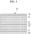
- FIG. 3 schematically illustrates a structure of an electrode assembly according to the second embodiment of the present disclosure.
- the electrode assembly 201 includes a plurality of unit cells 10, a first functional unit cell 110, a second functional unit cell 120, and a third functional unit cell 130.
- the third functional unit cell 130 is disposed at the center of the thickness direction of a plurality of unit cells 10, and is referred to as a central unit cell.
- the electrode assembly 201 may include at least one of the third functional unit cell 130.
- the central unit cell includes a negative electrode, a positive electrode, and a separator disposed between the negative electrode and the positive electrode.
- the positive electrode of the central unit cell includes a positive current collector and a positive active material layer disposed on at least one surface of the positive current collector and including a positive active material, and a second functional layer disposed on the positive active material layer.
- the positive active material has a first reference potential
- the second active material included in the second functional layer has a lower third reference potential than the first reference potential of the positive active material.
- the first reference potential may be, for example, in the range of about 3.3 V to about 4.3 V, or about 3.5 V to about 4.0 V.
- the positive current collector, the positive active material layer including the positive active material, and the negative electrode, and the separator are the same as described above in the electrode assembly according to the first embodiment described above referring to FIG. 1A , and thus will not be described.
- the second functional layer is disposed on the positive active material layer is, and the second functional layer includes a second active material having a third reference potential lower than the first reference potential.
- the third reference potential may be, for example, in the range of about 1.5 V to about 3.8 V or about 3.0 V to about 3.5 V.
- the third reference potential of the second active material satisfies the above-described numerical range and is lower than the first reference potential, a side reaction of the positive active material may be suppressed and safety may be secured.
- the third reference potential which is a reference potential of the second active material, is a reduction average potential based on a lithium metal (Li/Li + ).
- the second active material may be at least one among the active materials described above as the first active material.
- the second active material like the first active material has a lower reference potential than that of an active material included in the positive active material layer, that is, when a positive active material included in the positive active material layer is once selected, an active material having a lower third reference potential than the first reference potential may be selected as a second active material.
- a difference between the first reference potential and the third reference potential may be in the range of about 0.01 V to about 2.0 V, about 0.05 V to about 1.5 V, about 0.1 V to about 1.0 V about 0.1 V to about 0.6 V.
- excellent cycle-life characteristics and capacity characteristics may be exhibited.
- a plurality of unit cells 10 includes the first and second functional unit cells 110 and 120 on first and second outermost surfaces facing each other and further a third functional unit cell 130 at the center of a thickness direction, not only capacity may be secured, but also heat generation may be more effectively prevented, when a physical impact such as penetration and the like is applied thereto.
- FIG. 3 shows a case of including one third functional unit cell 130, for convenience. However, two and more third functional unit cells 130 may be included, if needed, which may be appropriately adjusted.
- FIG. 4 schematically illustrates a structure of an electrode assembly according to the third embodiment of the present disclosure.
- the electrode assembly 202 includes a plurality of unit cells 10 and a third functional unit cell 130.
- the third functional unit cell 130 is disposed at the center of the thickness direction of a plurality of unit cells 10, and is referred to as a central unit cell.
- the electrode assembly 202 may include at least one third functional unit cell 130.
- the central unit cell includes a negative electrode, a positive electrode, and a separator disposed between the negative electrode and the positive electrode.
- the positive electrode of the central unit cell includes a positive current collector, a positive active material layer disposed on at least one surface of the positive current collector and including a positive active material, and a second functional layer disposed on the positive active material layer.
- the positive active material has a first reference potential
- the second active material included in the second functional layer has a lower third reference potential than the first reference potential of the positive active material.
- the first reference potential may be, for example, in the range of about 3.3 V to about 4.3 V, or about 3.5 V to about 4.0 V.
- the positive current collector, the positive active material layer including the positive active material, and the negative electrode, and the separator are the same as described above in the electrode assembly according to the first embodiment described above referring to FIG. 1A , and thus will not be described.
- the second functional layer is disposed on the positive active material layer is, and the second functional layer includes a second active material having a third reference potential lower than the first reference potential.
- the central unit cell when the central unit cell is disposed at the center of a plurality of unit cells 10 in a thickness direction and includes a positive electrode including a second functional layer on a positive active material layer, wherein a second active material include in the second functional layer has a lower third reference potential than a first reference potential of a positive active material, and when a physical impact such as a penetration into a center of an electrode assembly and the like, is applied thereto, heat generation from the center may be reduced, and safety may be further improved.
- FIG. 4 shows that the third functional unit cell 130 includes one central unit cell for convenience.
- the third functional unit cell 130 may include two and more central unit cells, which may be appropriately adjusted.
- the same electrode assembly as illustrated in the first embodiment referring to FIG. 1A is used except for including not the first and second functional unit cells but the third functional unit cell 130.
- the present disclosure in another aspect provides a rechargeable battery including an electrode assembly according to one of the above embodiments.
- a rechargeable battery according to an embodiment includes an electrode assembly according to the above embodiments and modified embodiments thereof and a case housing the electrode assembly.
- the positive electrode, the negative electrode, and the separator included in each unit cell, outer unit cell, and central unit cell may be impregnated in an electrolyte.
- the electrolyte includes a non-aqueous organic solvent and a lithium salt.
- the non-aqueous organic solvent serves as a medium for transmitting ions taking part in the electrochemical reaction of a battery.
- the non-aqueous organic solvent may include a carbonate-based, ester-based, ether-based, ketone-based, alcohol-based, or aprotic solvent.
- the carbonate-based solvent may include dimethyl carbonate (DMC), diethyl carbonate (DEC), dipropyl carbonate (DPC), methylpropyl carbonate (MPC), ethylpropyl carbonate (EPC), methylethyl carbonate (MEC), ethylene carbonate (EC), propylene carbonate (PC), butylene carbonate (BC), and the like and the ester-based solvent may include methyl acetate, ethyl acetate, n-propyl acetate, dimethylacetate, methylpropionate, ethylpropionate, ⁇ -butyrolactone, decanolide, valerolactone, mevalonolactone, caprolactone, and the like.
- the ether-based solvent may include dibutyl ether, tetraglyme, diglyme, dimethoxyethane, 2-methyltetrahydrofuran, tetrahydrofuran, and the like and the ketone-based solvent may be cyclohexanone, and the like.
- the alcohol based solvent may include ethanol, isopropyl alcohol, and the like
- the aprotic solvent may include nitriles such as R-CN (wherein R is a C2 to C20 linear, branched, or cyclic hydrocarbon group, or may include a double bond, an aromatic ring, or an ether bond), and the like, amides such as dimethyl formamide, and the like, dioxolanes such as 1,3-dioxolane, and the like, sulfolanes, and the like.
- the non-aqueous organic solvent may be used alone or in a mixture.
- the mixture ratio may be controlled in accordance with a desirable battery performance.
- the carbonate-based solvent may include a mixture of a cyclic carbonate and a chain-type carbonate.
- the cyclic carbonate and the chain-type carbonate may be mixed together in a volume ratio of 1:1 to 1:9, performance of an electrolyte may be enhanced.
- the non-aqueous organic solvent of the present disclosure may further include an aromatic hydrocarbon-based organic solvent in addition to the carbonate based solvent.
- the carbonate-based solvent and the aromatic hydrocarbon-based organic solvent may be mixed in a volume ratio of about 1:1 to about 30:1.
- the aromatic hydrocarbon-based organic solvent may be an aromatic hydrocarbon-based compound of Chemical Formula 1.
- R 1 to R 6 are the same or different and are selected from hydrogen, a halogen, a C1 to C10 alkyl group, a haloalkyl group, and a combination thereof.
- aromatic hydrocarbon-based organic solvent may be selected from benzene, fluorobenzene, 1,2-difluorobenzene, 1,3-difluorobenzene, 1,4-difluorobenzene, 1,2,3-trifluorobenzene, 1,2,4-trifluorobenzene, chlorobenzene, 1,2-dichlorobenzene, 1,3-dichlorobenzene, 1,4-dichlorobenzene, 1,2,3-trichlorobenzene, 1,2,4-trichlorobenzene, iodobenzene, 1,2-diiodobenzene, 1,3-diiodobenzene, 1,4-diiodobenzene, 1,2,3-triiodobenzene, 1,2,4-triiodobenzene, toluene, fluorotoluene, 2,3-difluorotoluene, 2,4-di
- the non-aqueous electrolyte may further include an additive of vinylene carbonate or an ethylene carbonate-based compound of Chemical Formula 2 in order to improve cycle-life of a battery.
- R 7 and R 8 are the same or different and selected from hydrogen, a halogen, a cyano group (CN), a nitro group (NO 2 ), and a fluorinated C1 to C5 alkyl group, provided that at least one of R 7 and R 8 is selected from a halogen, a cyano group (CN), a nitro group (NO 2 ), and a fluorinated C1 to C5 alkyl group and R 7 and R 8 are not simultaneously hydrogen.
- Examples of the ethylene carbonate-based compound may be difluoroethylenecarbonate, chloroethylene carbonate, dichloroethylene carbonate, bromoethylene carbonate, dibromoethylene carbonate, nitroethylene carbonate, cyanoethylene carbonate, or fluoroethylene carbonate.
- the amount of the additive for improving cycle-life may be used within an appropriate range.
- the lithium salt dissolved in an organic solvent supplies a battery with lithium ions, basically operates the rechargeable lithium battery, and improves transportation of the lithium ions between a positive electrode and a negative electrode.
- the lithium salt include at least one supporting salt selected from LiPF 6 , LiBF 4 , LiSbF 6 , LiAsF 6 , LiN(SO 2 C 2 F 5 ) 2 , Li(CF 3 SO 2 ) 2 N, LiN(SO 3 C 2 F 5 ) 2 , LiC 4 F 9 SO 3 , LiClO 4 , LiAlO 2 , LiAlCl 4 , LiN(C x F 2x+1 SO 2 )(C y F 2y+1 SO 2 ) wherein, x and y are natural numbers, for example an integer ranging from 1 to 20), LiCI, Lil, and LiB(C 2 O 4 ) 2 (lithium bis(oxalato) borate: LiBOB).
- a concentration of the lithium salt may range from about 0.1 M to about
- the case may be pouch type, prismatic type or cylindrical depending on the shape of the electrode assembly. Each case may be used without any limitations as commonly used in the related art, and a detailed description thereof will be omitted herein.
- the rechargeable battery according to an embodiment of the present invention maintains a shape of the electrode assembly, and may be of a stack type corresponding to a pouch type or may be of a winding type or a jelly-roll type in which the electrode assembly is wound, for example, cylindrical or prismatic.
- FIG. 5 shows a cross-section of a cylindrical rechargeable battery according to an embodiment.
- the battery 1 includes a wound electrode assembly including a positive electrode 2 and a negative electrode 4 with a separator 3 interposed therebetween, a case 5 in which the electrode assembly is housed, and a sealing member 6 sealing the case 5.
- the positive electrode 10, the negative electrode 20, and the separator 30 may be impregnated in an electrolyte (not shown).
- FIG. 5 shows an embodiment in which the first functional layer 2c is disposed on the positive active material layer 2b, which is disposed on one surface of the positive current collector 2a and includes a positive active material.
- the present disclosure is not limited thereto.
- At least one of the rechargeable battery according to an embodiment may be included in a device.
- a device may be for example, one of a mobile phone, a tablet computer, a laptop computer, a power tool, a wearable electronic device, an electric vehicle, a hybrid electric vehicle, a plug-in hybrid electric vehicle, and a power storage device.
- the device to which the rechargeable battery is applied is well known in a related art and thus will not be specifically illustrated in the present specification.
- negative active material slurry 98 wt% of graphite, 0.8 wt% of carboxylmethyl cellulose, and 1.2 wt% of styrene-butadiene rubber were mixed in pure water to prepare negative active material slurry.
- the negative active material slurry was coated on both surfaces of a copper current collector and then, dried and compressed to manufacture a negative electrode having a negative active material layer.
- the negative electrode, a separator formed of a polyethylene and polypropylene multi-layered substrate, and the positive electrode in order were sequentially stacked to manufacture a unit cell.
- Positive active material slurry was prepared by mixing 94 wt% of a positive active material having a composition of LiNi 0.6 Co 0.2 Mn 0.2 O 2 and a reference potential of 3.67 V (a reduction average potential with reference to lithium metal (Li/Li + )), 3 wt% of a polyvinylidene fluoride binder, and 3 wt% of a ketjen black conductive material in an N-methylpyrrolidone solvent.
- a composition for a first functional layer was prepared by mixing 95 wt% of a first active material having a composition of LiFePO 4 and a reference potential of 3.15 V and 5 wt% of a polyvinylidene fluoride binder in an N-methylpyrrolidone solvent.
- the positive active material slurry was coated on both surfaces of an aluminum current collector and then, dried and compressed to form a positive active material layer, and the composition for a first functional layer was coated and then, dried and compressed to form a first functional layer on the positive active material layer. Accordingly, a positive electrode having the first functional layer on the positive active material layer was manufactured.
- a negative electrode was manufactured according to the same method as the above (1).
- the negative electrode, a separator formed of a polyethylene and polypropylene multi-layered substrate, and the positive electrode manufactured in the above (2) in order were sequentially stacked to manufacture an outer unit cell.
- the thirteen (13) unit cells manufactured in the above (1) were overlapped in a thickness direction to manufacture a stack.
- the outer unit cells manufactured in the above (2) were respectively stacked on the outermost first and second surfaces of the stack to manufacture an electrode assembly having a structure shown in FIG. 1B and then, housed in a case, and an electrolyte was injected therein to manufacture a rechargeable battery cell.
- the electrolyte was prepared by dissolving 1.0 M LiPF 6 in a mixed solvent (50 : 50 volume ratio) of ethylene carbonate (EC) and diethyl carbonate (DEC).
- a unit cell was manufactured according to the same method as Example 1.
- An outer unit cell was manufactured according to the same method as Example 1.
- Positive active material slurry was prepared by mixing 94 wt% of a positive active material having a composition of LiNi 0.6 Co 0.2 Mn 0.2 O 2 and a reference discharge average potential of 3.67 V, 3 wt% of a polyvinylidene fluoride binder, and 3 wt% of a ketjen black conductive material in an N-methylpyrrolidone solvent.
- a first active material having a composition of LiFePO 4 and a reference potential of 3.15 V and 5 wt% of a polyvinylidene fluoride binder were mixed in an N-methylpyrrolidone solvent to prepare a composition for a first functional layer.
- the positive active material slurry was coated on both surfaces of an aluminum current collector and then, dried and compressed to form a positive active material layer, and on the positive active material layer, the composition for a first functional layer was coated and then, dried and compressed to form a first functional layer. Accordingly, a positive electrode having the first functional layer on the positive active material layer was manufactured.
- a negative electrode was manufactured according to the same method as the above (1).
- the negative electrode, a separator formed of a polyethylene and polypropylene multi-layered substrate, and the positive electrode manufactured in the above (2) were sequentially stacked to manufacture a central unit cell.
- the thirteen (13) unit cells manufactured in the (1) of Example 2 were overlapped in a thickness direction to manufacture a stack.
- the outer unit cells manufactured in the (2) of Example 2 were respectively stacked on the outermost first and second surfaces of the stack manufactured in the (2), the central unit cell manufactured in the (3) of Example 2 was disposed at the center of the thickness direction of the stack to manufacture an electrode assembly having a structure shown in FIG. 3 , the electrode assembly was housed in a case, and an electrolyte was injected therein to manufacture a rechargeable battery cell.
- the electrolyte included 1.0 M LiPF 6 dissolved in a mixed solvent (a volume ratio of 50 : 50) of ethylene carbonate (EC) and diethyl carbonate (DEC).
- a unit cell was manufactured according to the same method as Example 1.
- a central unit cell was manufactured according to the same method as Example 2.
- the thirteen (13) unit cells manufactured in the above (1) of Example 3 were overlapped in a thickness direction to manufacture a stack.
- the central unit cell manufactured in the (2) of Example 3 was disposed at the center of the thickness direction of the stack manufactured in the (2) to manufacture an electrode assembly having a structure shown in FIG. 4 and housed in a case, and an electrolyte was injected theretinto to manufacture a rechargeable battery cell.
- the electrolyte included 1.0 M LiPF 6 dissolved in a mixed solvent (a volume ratio of 50 : 50) of ethylene carbonate (EC) and diethyl carbonate (DEC).
- a unit cell was manufactured according to the same method as Example 1.
- the thirteen (13) unit cells manufactured in the (1) were overlapped in a thickness direction to manufacture an electrode assembly.
- the electrode assembly was housed in a case, and an electrolyte was injected thereinto to manufacture a rechargeable battery cell.
- the electrolyte included 1.0 M LiPF 6 dissolved in a mixed solvent (a volume ratio of 50 : 50) of ethylene carbonate (EC) and diethyl carbonate (DEC).
- a unit cell was manufactured according to the same method as Example 1.
- Positive active material slurry was prepared by mixing 94 wt% of a positive active material having a composition of LiNi 0.6 Co 0.2 Mn 0.2 O 2 and a reference potential of 3.67 V, 3 wt% of a polyvinylidene fluoride binder, and 3 wt% of a ketjen black conductive material in an N-methylpyrrolidone solvent.
- 94 wt% of a first active material having a composition of LiCoO 2 and a reference potential of 3.85 V, 3 wt% of a polyvinylidene fluoride binder, and 3 wt% of a ketjen black conductive material were mixed in an N-methylpyrrolidone solvent to prepare a composition for a first functional layer.
- the positive active material slurry was coated on both surfaces of an aluminum current collector and then, dried and compressed to form a positive active material layer, and on the positive active material layer, the composition for a first functional layer was coated and then, dried and compressed to form a first functional layer. Accordingly, a positive electrode having the first functional layer on the positive active material layer was manufactured.
- a negative electrode was manufactured according to the same method as the above (1).
- the negative electrode, a separator formed of a polyethylene and polypropylene multi-layered substrate, and the positive electrode manufactured in the above (2) were sequentially stacked to manufacture an outer unit cell.
- the thirteen (13) unit cells manufactured in the (1) were overlapped in a thickness direction to manufacture a stack.
- the outer unit cells manufactured in the (2) were respectively laminated on the outermost first and second surfaces of the stack to manufacture an electrode assembly having a structure shown in FIG. 1 , the electrode assembly was housed in a case, and an electrolyte was injected thereinto to manufacture a rechargeable battery cell.
- the electrolyte included 1.0 M LiPF 6 dissolved in a mixed solvent (a volume ratio of 50 : 50) of ethylene carbonate (EC) and diethyl carbonate (DEC).
- the rechargeable battery cells according to Examples 1 to 3 and Comparative Examples 1 to 2 were respectively charged at a constant current and constant voltage of 0.1 C and 4.3 V and with a cut-off at 0.05 C, paused for 10 minutes, discharged at a constant current of 0.1 C with a cut-off at 2.7 V, and paused for 10 minutes, which is regarded as one cycle, and after performing one charge and discharge cycle, charge and discharge capacities of the rechargeable battery cells were measured and then, shown in Table 1.
- the rechargeable battery cells having a functional layer including an active material having a lower reference potential than that of an active material included in an active material layer according to Examples 1 to 3 showed an excellent capacity retention compared with the rechargeable battery cells having no functional layer or a functional layer including an active material having a higher reference potential than that of an active material included in an active material layer according to Comparative Examples 1 and 2.
- the penetration experiment was performed by charging the rechargeable lithium battery cells at 0.5 C and 4.3 V with a cut-off at 0.05 C, and after about one hour, a pin having a diameter of 3 mm was used to completely penetrate a center of the cells at 80 Mm/sec.
- Table 2 numbers indicate the number of cells having non-ignition, smoke generation, and ignition.
- Table 2 Non-ignition Smoke generation Ignition Example 1 7 3 0 Example 2 8 2 0 Example 3 5 2 3 Comparative Example 1 0 0 10 Comparative Example 2 0 0 10
- the cells having a functional layer including an active material having a lower reference potential than that of an active material included in an active material layer according to Examples 1 to 3 showed excellent safety compared with the cells having no functional layer or a functional layer including an active material having a higher reference potential than that of an active material included in an active material layer according to Comparative Examples 1 and 2.
Abstract
Description
- The present disclosure relates to an electrode assembly and a rechargeable battery including the same.
- A portable information device such as a cell phone, a laptop, smart phone, and the like or an electric vehicle has used a rechargeable lithium battery having high energy density and easy portability as a driving power source.
- Particularly, research on use of a rechargeable lithium battery as a power source for a hybrid or electric vehicle or a power storage by using high energy density characteristics has recently been actively made.
- One of the main research tasks on the rechargeable lithium battery applied to a vehicle and the like is high capacity. For example, a method of increasing a thickness and/or a size thereof has been suggested to realize high capacity of the rechargeable lithium battery.
- However, when the rechargeable lithium battery becomes thicker and has a larger size in this way, safety of the rechargeable lithium battery may be greatly deteriorated due to a heat dissipation difference inside/outside of the battery.
- Accordingly, research on development of technology capable of improving the safety of the rechargeable lithium battery and simultaneously, securing high power and a high energy density thereof is being variously made.
- The present disclosure provides an electrode assembly having improved safety while having excellent cycle-life and capacity characteristics and a rechargeable battery including the same.
- In one aspect, the present disclosure provides an electrode assembly including a plurality of unit cells overlapping in a thickness direction; a first functional unit cell disposed on an outermost first surface of the plurality of unit cells; and a second functional unit cell on an outermost second surface that is opposed to the first surface, wherein each of the first functional unit cell and the second functional unit cell include an outer unit cell including a negative electrode, a positive electrode, and a separator disposed between the negative electrode and the positive electrode, wherein the positive electrode includes a positive current collector, a positive active material layer disposed on at least one surface of the positive current collector and including a positive active material having a first reference potential, and a first functional layer disposed on the positive active material layer and including a first active material having a lower second reference potential than the first reference potential.
- The term "functional unit cell" may refer to a unit cell dedicated to perform a function of preventing heat generation. The term "functional layer" may refer to a layer dedicated to perform the function above as well.
- In another aspect, the present disclosure provides an electrode assembly including a plurality of unit cells overlapping in a thickness direction; and the third functional unit cell disposed in the center in the thickness direction of the plurality of unit cells, wherein the third functional unit cell includes a central unit cell including a negative electrode, a positive electrode, and a separator disposed between the negative electrode and the positive electrode, the positive electrode includes a positive current collector, a positive active material layer disposed on at least one surface of the positive current collector and including a positive active material having a first reference potential, and a second functional layer disposed on the positive active material layer and including a second active material having a lower third reference potential than the first reference potential.
- In another aspect, the present disclosure provides a rechargeable battery including the electrode assembly.
- When the electrode assembly according to an embodiment is applied, a rechargeable battery having improved safety as well as excellent cycle-life characteristics and capacity characteristics may be realized.
-
-
FIG. 1A schematically illustrates a structure of an electrode assembly according to the first embodiment of the present disclosure. -
FIG. 1B schematically illustrates a positive electrode according to another embodiment. -
FIG. 2 illustrates an exemplary variation ofFIG. 1B . -
FIG. 3 schematically illustrates a structure of an electrode assembly according to the second embodiment of the present disclosure. -
FIG. 4 schematically illustrates a structure of an electrode assembly according to the third embodiment of the present disclosure. -
FIG. 5 schematically illustrates a structure of a cylindrical rechargeable battery according to an embodiment. - Hereinafter, various embodiments of the present invention will be described in detail with reference to the accompanying drawings so that those skilled in the art may easily carry out the present invention. However, this disclosure may be embodied in many different forms and is not construed as limited to the example embodiments set forth herein.
- In order to clearly illustrate the present invention, parts that are not related to the description are omitted, and the same or similar components are denoted by the same reference numerals throughout the specification.
- Sizes and thicknesses of components in the drawings are arbitrarily expressed for convenience of description and, thus, the present invention is not limited by the drawings.
- In addition, unless explicitly described to the contrary, the word "comprise" and variations such as "comprises" or "comprising", will be understood to imply the inclusion of stated elements but not the exclusion of any other elements.
- In one aspect of the present disclosure, an electrode assembly having improved safety as well as excellent cycle-life characteristics and capacity characteristics is provided.
- Hereinafter, the reference potential of a positive active material means a discharge average potential based on lithium metal as a reference (Li/Li+). Also, the unit cell is an electrode assembly in which a positive electrode, a separator, and a negative electrode are sequentially stacked.
-
FIG. 1A schematically illustrates a structure of an electrode assembly according to the first embodiment of the present disclosure. - Referring to
FIG. 1A , theelectrode assembly 200 according to the first embodiment includes a plurality ofunit cells 10, a firstfunctional unit cell 110, and a secondfunctional unit cell 120. - The plurality of
unit cells 10 are overlapped in the thickness direction.FIG. 1A shows a specific number ofunit cells 10 stacked for convenience, but the number of stackedunit cells 10 may be appropriately adjusted as needed. - As shown in
FIG. 1A , the firstfunctional unit cell 110 and the secondfunctional unit cell 120 may be disposed at the outermost portion, and will be referred to as an outer unit cell in the following description. - The outer unit cell includes a negative electrode 4, a
positive electrode 2, and aseparator 3 interposed between the negative electrode and the positive electrode, as shown in an enlarged manner. - The
positive electrode 2 includes a positivecurrent collector 2a and a positiveactive material layer 2b disposed on at least one surface of the positivecurrent collector 2a and including a positive active material, and a firstfunctional layer 2c disposed on the positiveactive material layer 2b and including a first active material.FIG. 1A shows only a structure of thepositive electrode 2 having a positive active material layer disposed on one surface of a current collector, but the positive active material may be disposed on both surfaces of the current collector, and in addition, the structure ofFIG. 1A shows that the firstfunctional layer 2c is disposed on one surface of the positiveactive material layer 2b and contacts theseparator 3, but as shown inFIG. 1B , when the positiveactive material layers current collector 2a, the firstfunctional layers active material layers - In an embodiment, the positive active material included in the positive active material layer has a first reference potential, and a first active material included in the first functional layer has a lower second reference potential than the first reference potential of the positive active material.
- The first reference potential may be, for example, in the range of about 3.3 V to about 4.3 V, about 3.5 V to about 4.0 V, or about 3.6 V to about 3.8 V.
- As used herein, the first reference potential, which is the reference potential of the positive active material, is a reduction average potential based on a lithium metal (Li/Li+).
- On the other hand, the positive active material may include a compound (lithiated intercalation compound) capable of intercalating and deintercallating lithium. The positive active material may be, for example, at least one composite oxides of a metal selected from cobalt, manganese, nickel, and a combination thereof, and lithium. More specifically, it may include LiaA1-bXbD2 (0.90 ≤ a ≤ 1.8, 0 ≤ b ≤ 0.5); LiaA1-bXbO2-cDc (0.90 ≤ a ≤ 1.8, 0 ≤ b ≤ 0.5, 0 ≤ c ≤0.05); LiaE1-bXbO2-cDc (0.90 ≤ a ≤1.8, 0 ≤ b ≤ 0.5, 0 ≤ c ≤ 0.05); LiaE2-bXbO4-cDc (0.90 ≤ a ≤ 1.8, 0 ≤ b ≤ 0.5, 0 ≤ c ≤0.05); LiaNi1-b-cCobXcDα (0.90 ≤ a ≤ 1.8, 0 ≤ b ≤ 0.5, 0 ≤ c ≤ 0.5, 0 < α ≤2); LiaNi1-b-cCobXcO2-αTα (0.90 ≤ a ≤ 1.8, 0 ≤ b ≤ 0.5, 0 ≤ c ≤ 0.05, 0 < α < 2); LiaNi1-b-cCObXcO2-αT2 (0.90 ≤ a ≤ 1.8, 0 ≤ b ≤ 0.5, 0 ≤ c ≤ 0.05, 0 < α < 2); LiaNi1-b-cMnbXcDα (0.90 ≤ a ≤ 1.8, 0 ≤ b ≤ 0.5, 0 ≤ c ≤0.05, 0 < α ≤ 2); LiaNi1-b-cMnbXcO2-αTα (0.90 ≤ a ≤ 1.8, 0 ≤ b ≤ 0.5, 0 ≤ c ≤ 0.05, 0 < α < 2); LiaNi1-b-cMnbXcO2-αT2 ( 0.90 ≤ a ≤ 1.8, 0 ≤ b ≤ 0.5, 0 ≤ c ≤ 0.05, 0 < α < 2); LiaNibEcGdO2 (0.90 ≤ a ≤ 1.8, 0 ≤ b ≤ 0.9, 0 ≤ c ≤ 0.5, 0.001 ≤ d ≤ 0.1); LiaNibCOcMndGeO2 (0.90 ≤ a ≤ 1.8, 0 ≤ b ≤ 0.9, 0 ≤ c ≤ 0.5, 0 ≤ d ≤0.5, 0.001 ≤ e ≤ 0.1); LiaNiGbO2 (0.90 ≤ a ≤1.8, 0.001 ≤ b ≤ 0.1) LiaCoGbO2 (0.90 ≤ a ≤ 1.8, 0.001 ≤ b ≤ 0.1); LiaMn1-bGbO2 (0.90 ≤ a ≤ 1.8, 0.001 ≤ b ≤ 0.1); LiaMn2GbO4 (0.90 ≤ a ≤ 1.8, 0.001 ≤ b ≤ 0.1); QO2; QS2; LiQS2; V2O5; LiV2O5; LiZO2; LiNiVO4, or a combination thereof.
- In chemical formulae, A is selected from Ni, Co, Mn, and a combination thereof; X is selected from Al, Ni, Co, Mn, Cr, Fe, Mg, Sr, V, a rare earth element, and a combination thereof; D is selected from O, F, S, P, and a combination thereof; E is selected from Co, Mn, and a combination thereof; T is selected from F, S, P, and a combination thereof; G is selected from Al, Cr, Mn, Fe, Mg, La, Ce, Sr, V, and a combination thereof; Q is selected from Ti, Mo, Mn, and a combination thereof; and Z is selected from Cr, V, Fe, Sc, Y, and a combination thereof.
- In the positive electrode, an amount of the positive active material may be about 90 wt% to about 99.8 wt% based on a total weight of the positive active material layer.
- As needed, the positive active material layer may further include a binder and a conductive material. Herein, the binder and the conductive material may be included in an amount of about 0.1 wt% to about 5 wt%, respectively based on a total weight of the positive active material layer.
- The binder improves binding properties of positive active material particles with one another and with a current collector. Examples of the binder may be polyvinyl alcohol, carboxylmethyl cellulose, hydroxypropyl cellulose, diacetyl cellulose, polyvinylchloride, carboxylated polyvinylchloride, polyvinylfluoride, an ethylene oxide-containing polymer, polyvinylpyrrolidone, polyurethane, polytetrafluoroethylene, polyvinylidene fluoride, polyethylene, polypropylene, a styrene-butadiene rubber, an acrylated styrene-butadiene rubber, an epoxy resin, nylon, and the like, but are not limited thereto.
- The conductive material is included to provide electrode conductivity. Any electrically conductive material may be used as a conductive material unless it causes a chemical change. Examples of the conductive material may include a carbon-based material such as natural graphite, artificial graphite, carbon black, acetylene black, ketjen black, a carbon fiber and the like; a metal-based material of a metal powder or a metal fiber including copper, nickel, aluminum, silver, and the like; a conductive polymer such as a polyphenylene derivative; or a mixture thereof.
- The first functional layer is disposed on the positive active material layer and the first functional layer includes a first active material having a lower second reference potential than the first reference potential. For example, the second reference potential may be, for example, in a range of about 1.5 V to about 3.8 V, about 2.0 V to about 3.6V, about 2.5 V to about 3.5V, about 3.0 V to about 3.5 V, or about 3.1 V to about 3.3V. When the second reference potential of the first active material satisfies the above-described numerical range and is lower than the first reference potential, a side reaction of the positive active material may be suppressed and safety may be secured.
- As used herein, the second reference potential, which is the reference potential of the first active material, is a reduction average potential based on a lithium metal (Li/Li+).
- The first active material may be, for example, LiaFe1-gGgPO4 (0.90 ≤ a ≤ 1.8, 0 ≤ g ≤ 0.5); LiaMn1-gGgPO4 (0.90 ≤ a ≤ 1.8, 0 ≤ g ≤ 0.5); LiaCO1-gGgPO4 (0.90 ≤ a ≤ 1.8, 0 ≤ g ≤ 0.5); Li4-xMxTiyO12-z (0 ≤ x ≤ 3, 1 ≤ y ≤ 5, -0.3 ≤ z ≤ 0.3), or a combination thereof. In the above chemical formulae, G is selected from Al, Cr, Mn, Fe, Mg, La, Ce, Sr, V, and a combination thereof; and M is selected from Mg, La, Tb, Gd, Ce, Pr, Nd, Sm, Ba, Sr, Ca, or a combination thereof.
- The first active material may be an active material having a lower reference potential than the first reference potential, among the active materials. In other words, when the positive active material included in the positive active material layer is once selected, an active material having a lower second reference potential than the first reference potential of the positive active material may be selected as the first active material.
- In this way, when the first active material is selected to have a lower reference potential than that of the positive active material included in the active material layer, a side reaction of the positive electrode may be suppressed and safety of a positive electrode may be improved.
- The first functional layer may further include a binder. When the first functional layer includes the binder, the first active material may be included in an amount of about 90 wt% to about 99.8 wt% based on a total weight of the first functional layer, and the binder may be included in an amount of about 0.2 wt% to about 10 wt% based on a total weight of the first functional layer. According to an embodiment, the binder may be included in an amount of about 1 wt% to about 6 wt%.
- In addition, as shown in
FIG. 1B , when the positive active material layers are disposed on both surfaces of a current collector, and the first functional layers are respectively disposed on the positive active material layers, the positive active material layers on both surfaces of the current collector are respectively called to be a first positive active material layer and a second positive active material layer, and the first functional layers are respectively called to be a 1a functional layer and a 1b functional layer, and herein, positive active materials included in the first and second positive active material layers may be the same or different each other among the positive active materials having a first reference potential, and active materials included in the 1a and 1b functional layers also may be the same or different each other among the active materials having a second reference potential. - In the outer unit cell, a difference between the first reference potential and the second reference potential may be in the range of about 0.01 V to about 2.0 V, about 0.05 V to about 1.5 V, about 0.1 V to about 1.0 V about 0.1 V to about 0.6 V. When the difference in the reference potentials of the positive active material included in the positive active material layer and the first active material included in the first functional layer satisfies the range, excellent cycle-life characteristics and capacity characteristics may be exhibited.
- The first functional layer may have a thickness of about 0.5µm to about 8µm and according to an embodiment, a thickness of about 2µm to about 5µm. When the first functional layer has a thickness within the range, the first functional layer substantially covers the positive active material layer as well as maintains conductivity, and a formation effect of the first functional layer may be further appropriately obtained.
- In this way, when the outer unit cell includes a positive electrode including the first functional layer disposed on the positive active material layer, wherein a first active material included in the first functional layer has a lower second reference potential than a first reference potential of the positive active material, a side reaction may be reduced by preventing an overvoltage of the positive active material layer, and ignition may be prevented by disposing the first active material having a low reference potential on the surface, lowering a heat value when a short circuit internally occurs, and thus securing safety.
- The positive current collector may be, for example, selected from an aluminum foil, a nickel foil, or a combination thereof.
- On the other hand, the negative electrode includes a negative electrode collector and a negative active material layer disposed on at least one surface of the negative electrode collector. The negative active material layer includes a negative active material.
- The negative active material may include a material that reversibly intercalates/deintercalates lithium ions, a lithium metal, a lithium metal alloy, a material being capable of doping/dedoping lithium, or transition metal oxide.
- The material that reversibly intercalates/deintercalates lithium ions may be a carbon material, that is, a generally-used carbon-based negative active material in a rechargeable lithium battery. Examples of the carbon-based negative active material may be crystalline carbon, amorphous carbon, or a combination thereof. The crystalline carbon may be shapeless (unspecified shape), or sheet, flake, spherical, or fiber shaped natural graphite or artificial graphite. The amorphous carbon may be a soft carbon, a hard carbon, a mesophase pitch carbonization product, fired coke, and the like.
- The lithium metal alloy includes an alloy of lithium and a metal selected from Na, K, Rb, Cs, Fr, Be, Mg, Ca, Sr, Si, Sb, Pb, In, Zn, Ba, Ra, Ge, Al, and Sn.
- The material being capable of doping/dedoping lithium may be a silicon-based material, for example, Si, SiOx (0<x<2), a Si-Q alloy (wherein Q is an element selected from an alkali metal, an alkaline-earth metal, a Group 13 element, a Group 14 element, a Group 15 element, a Group 16 element, a transition metal, a rare earth element, and a combination thereof, and not Si), a Si-carbon composite, Sn, SnO2, a Sn-R alloy (wherein R is an element selected from an alkali metal, an alkaline-earth metal, a Group 13 element, a Group 14 element, a Group 15 element, a Group 16 element, a transition metal, a rare earth element, and a combination thereof, and not Sn), a Sn-carbon composite, and the like. At least one of these materials may be mixed with SiO2. The elements Q and R may be selected from Mg, Ca, Sr, Ba, Ra, Sc, Y, Ti, Zr, Hf, Rf, V, Nb, Ta, Db, Cr, Mo, W, Sg, Tc, Re, Bh, Fe, Pb, Ru, Os, Hs, Rh, Ir, Pd, Pt, Cu, Ag, Au, Zn, Cd, B, Al, Ga, Sn, In, Ge, P, As, Sb, Bi, S, Se, Te, Po, and a combination thereof.
- The transition metal oxide includes lithium titanium oxide.
- In the negative active material layer, the negative active material may be included in an amount of about 95 wt% to about 99 wt% based on a total weight of the negative active material layer.
- The negative active material layer includes a negative active material and a binder, and may further include a conductive material as needed.
- In the negative active material layer, the negative active material may be included in an amount of about 95 wt% to about 99 wt% based on a total weight of the negative active material layer. In the negative active material layer, a content of the binder may be about 1 wt% to about 5 wt% based on a total weight of the negative active material layer. When the negative active material layer includes a conductive material, the negative active material layer includes about 90 wt% to about 99.4 wt% of the negative active material, about 0.5 wt% to about 5 wt% of the binder, and about 0.1 wt% to about 5 wt% of the conductive material.
- The binder improves binding properties of negative active material particles with one another and with a current collector. The binder may be a non-water-soluble binder, a water-soluble binder, or a combination thereof.
- The non-water-soluble binder may be polyvinylchloride, carboxylated polyvinylchloride, polyvinylfluoride, an ethylene oxide-containing polymer, polyvinylpyrrolidone, polyurethane, polytetrafluoroethylene, polyvinylidene fluoride, polyethylene, polypropylene, polyamideimide, polyimide, or a combination thereof.
- The water-soluble binder may be a styrene-butadiene rubber, an acrylated styrene-butadiene rubber, polyvinyl alcohol, sodium polyacrylate, a copolymer of propylene and a C2 to C8 olefin, a copolymer of (meth)acrylic acid and (meth)acrylic acid alkyl ester, or a combination thereof.
- When the water-soluble binder is used as a negative electrode binder, a cellulose-based compound may be further used to provide viscosity as a thickener. The cellulose-based compound includes one or more of carboxylmethyl cellulose, hydroxypropylmethyl cellulose, methyl cellulose, or alkali metal salts thereof. The alkali metals may be Na, K, or Li. The thickener may be included in an amount of about 0.1 parts by weight to about 3 parts by weight based on 100 parts by weight of the negative active material.
- The conductive material is included to provide electrode conductivity. Any electrically conductive material may be used as a conductive material unless it causes a chemical change. Examples of the conductive material include a carbon-based material such as natural graphite, artificial graphite, carbon black, acetylene black, ketjen black, denka black, a carbon fiber, and the like; a metal-based material of a metal powder or a metal fiber including copper, nickel, aluminum, silver, and the like; a conductive polymer such as a polyphenylene derivative; or a mixture thereof.
- The negative electrode collector may be, for example, selected from a copper foil, a nickel foil, a stainless steel foil, a titanium foil, a nickel foam, a copper foam, a polymer substrate coated with a conductive metal, and a combination thereof.
- Meanwhile, the separator may include any materials generally used in the rechargeable lithium battery as long as separating a negative electrode from a positive electrode and providing a transporting passage for lithium ions. In other words, the separator may have a low resistance to ion transportation and an excellent impregnation for an electrolyte. The separator may be, for example, selected from a glass fiber, polyester, polyethylene, polypropylene, polytetrafluoroethylene, or a combination thereof. It may have a form of a non-woven fabric or a woven fabric. Alternatively, a separator including a coating layer using a composition including a ceramic component or a polymer material on the substrate in order to ensure heat resistance or mechanical strength may be used. Optionally, it may have a mono-layered or multi-layered structure.
- Next, the plurality of
unit cells 10 overlapping in athickness direction 10 is described. - Each
unit cell 10 includes a negative electrode, a positive electrode, and a separator disposed between the negative electrode and the positive electrode. - Herein, the negative electrode and the separator are the same as those described in the negative electrode and separator of the above outer unit cell, and thus detailed descriptions thereof will be omitted.
- The positive electrode includes a positive current collector and a positive active material layer disposed on at least one surface of the positive current collector and including a positive active material. Herein, detailed descriptions of the positive current collector and the positive active material layer are the same as described in the positive electrode of the aforementioned outer unit cell, and thus detailed descriptions thereof will be omitted. That is, the positive electrode of each
unit cell 10 has the same structure and feature as the positive electrode of the aforementioned outer unit cell except that it does not include the first functional layer. -
FIG. 2 illustrates an exemplary variation ofFIG. 1B . - Referring to
FIG. 2 , theelectrode assembly 210 according to the exemplary variation may include a plurality of first and secondfunctional unit cells - For convenience,
FIG. 2 illustrates that theelectrode assembly 210 includes two firstfunctional unit cells 110 and two secondfunctional unit cells 120. However, if necessary, the number of the first and secondfunctional unit cells - In this exemplary variation, other features are the same as the electrode assembly according to the first embodiment described above referring to
FIG. 1A , except that the first and secondfunctional unit cells -
FIG. 3 schematically illustrates a structure of an electrode assembly according to the second embodiment of the present disclosure. - Referring to
FIG. 3 , theelectrode assembly 201 according to the second embodiment includes a plurality ofunit cells 10, a firstfunctional unit cell 110, a secondfunctional unit cell 120, and a thirdfunctional unit cell 130. - The third
functional unit cell 130 is disposed at the center of the thickness direction of a plurality ofunit cells 10, and is referred to as a central unit cell. Herein, theelectrode assembly 201 may include at least one of the thirdfunctional unit cell 130. - The central unit cell includes a negative electrode, a positive electrode, and a separator disposed between the negative electrode and the positive electrode.
- In the present embodiment, the positive electrode of the central unit cell includes a positive current collector and a positive active material layer disposed on at least one surface of the positive current collector and including a positive active material, and a second functional layer disposed on the positive active material layer.
- The positive active material has a first reference potential, and the second active material included in the second functional layer has a lower third reference potential than the first reference potential of the positive active material.
- The first reference potential may be, for example, in the range of about 3.3 V to about 4.3 V, or about 3.5 V to about 4.0 V.
- In the present embodiment, the positive current collector, the positive active material layer including the positive active material, and the negative electrode, and the separator are the same as described above in the electrode assembly according to the first embodiment described above referring to
FIG. 1A , and thus will not be described. - The second functional layer is disposed on the positive active material layer is, and the second functional layer includes a second active material having a third reference potential lower than the first reference potential.
- The third reference potential may be, for example, in the range of about 1.5 V to about 3.8 V or about 3.0 V to about 3.5 V. When the third reference potential of the second active material satisfies the above-described numerical range and is lower than the first reference potential, a side reaction of the positive active material may be suppressed and safety may be secured.
- As used herein, the third reference potential, which is a reference potential of the second active material, is a reduction average potential based on a lithium metal (Li/Li+).
- The second active material may be at least one among the active materials described above as the first active material. The second active material like the first active material has a lower reference potential than that of an active material included in the positive active material layer, that is, when a positive active material included in the positive active material layer is once selected, an active material having a lower third reference potential than the first reference potential may be selected as a second active material.
- In the central unit cell, a difference between the first reference potential and the third reference potential may be in the range of about 0.01 V to about 2.0 V, about 0.05 V to about 1.5 V, about 0.1 V to about 1.0 V about 0.1 V to about 0.6 V. When the difference in the reference potentials of the positive active material included in the positive active material layer and the first active material included in the first functional layer satisfies the range, excellent cycle-life characteristics and capacity characteristics may be exhibited.
- As shown in the embodiment, when a plurality of
unit cells 10 includes the first and secondfunctional unit cells functional unit cell 130 at the center of a thickness direction, not only capacity may be secured, but also heat generation may be more effectively prevented, when a physical impact such as penetration and the like is applied thereto. -
FIG. 3 shows a case of including one thirdfunctional unit cell 130, for convenience. However, two and more thirdfunctional unit cells 130 may be included, if needed, which may be appropriately adjusted. - In a second embodiment, other constitutions except for further including the third
functional unit cell 130 are the same as the electrode assembly of the first embodiment illustrated referring toFIG. 1A . -
FIG. 4 schematically illustrates a structure of an electrode assembly according to the third embodiment of the present disclosure. - Referring to
FIG. 4 , theelectrode assembly 202 according to the third embodiment includes a plurality ofunit cells 10 and a thirdfunctional unit cell 130. - The third
functional unit cell 130 is disposed at the center of the thickness direction of a plurality ofunit cells 10, and is referred to as a central unit cell. Herein, theelectrode assembly 202 may include at least one thirdfunctional unit cell 130. - The central unit cell includes a negative electrode, a positive electrode, and a separator disposed between the negative electrode and the positive electrode.
- In the present embodiment, the positive electrode of the central unit cell includes a positive current collector, a positive active material layer disposed on at least one surface of the positive current collector and including a positive active material, and a second functional layer disposed on the positive active material layer.
- The positive active material has a first reference potential, and the second active material included in the second functional layer has a lower third reference potential than the first reference potential of the positive active material.
- The first reference potential may be, for example, in the range of about 3.3 V to about 4.3 V, or about 3.5 V to about 4.0 V.
- In the present embodiment, the positive current collector, the positive active material layer including the positive active material, and the negative electrode, and the separator are the same as described above in the electrode assembly according to the first embodiment described above referring to
FIG. 1A , and thus will not be described. - The second functional layer is disposed on the positive active material layer is, and the second functional layer includes a second active material having a third reference potential lower than the first reference potential.
- Specific illustration of the second functional layer is the same as aforementioned in the electrode assembly of the second embodiment illustrated referring to
FIG. 3 and thus will be omitted here. - As shown in the embodiment, when the central unit cell is disposed at the center of a plurality of
unit cells 10 in a thickness direction and includes a positive electrode including a second functional layer on a positive active material layer, wherein a second active material include in the second functional layer has a lower third reference potential than a first reference potential of a positive active material, and when a physical impact such as a penetration into a center of an electrode assembly and the like, is applied thereto, heat generation from the center may be reduced, and safety may be further improved. -
FIG. 4 shows that the thirdfunctional unit cell 130 includes one central unit cell for convenience. However, the thirdfunctional unit cell 130 may include two and more central unit cells, which may be appropriately adjusted. - In a third embodiment, the same electrode assembly as illustrated in the first embodiment referring to
FIG. 1A is used except for including not the first and second functional unit cells but the thirdfunctional unit cell 130. - On the other hand, the present disclosure in another aspect provides a rechargeable battery including an electrode assembly according to one of the above embodiments.
- A rechargeable battery according to an embodiment includes an electrode assembly according to the above embodiments and modified embodiments thereof and a case housing the electrode assembly.
- Specific illustration of the electrode assembly is the same as above and will be omitted here.
- In the above electrode assemblies, the positive electrode, the negative electrode, and the separator included in each unit cell, outer unit cell, and central unit cell may be impregnated in an electrolyte.
- The electrolyte includes a non-aqueous organic solvent and a lithium salt.
- The non-aqueous organic solvent serves as a medium for transmitting ions taking part in the electrochemical reaction of a battery.
- The non-aqueous organic solvent may include a carbonate-based, ester-based, ether-based, ketone-based, alcohol-based, or aprotic solvent. The carbonate-based solvent may include dimethyl carbonate (DMC), diethyl carbonate (DEC), dipropyl carbonate (DPC), methylpropyl carbonate (MPC), ethylpropyl carbonate (EPC), methylethyl carbonate (MEC), ethylene carbonate (EC), propylene carbonate (PC), butylene carbonate (BC), and the like and the ester-based solvent may include methyl acetate, ethyl acetate, n-propyl acetate, dimethylacetate, methylpropionate, ethylpropionate, γ-butyrolactone, decanolide, valerolactone, mevalonolactone, caprolactone, and the like. The ether-based solvent may include dibutyl ether, tetraglyme, diglyme, dimethoxyethane, 2-methyltetrahydrofuran, tetrahydrofuran, and the like and the ketone-based solvent may be cyclohexanone, and the like. The alcohol based solvent may include ethanol, isopropyl alcohol, and the like, and the aprotic solvent may include nitriles such as R-CN (wherein R is a C2 to C20 linear, branched, or cyclic hydrocarbon group, or may include a double bond, an aromatic ring, or an ether bond), and the like, amides such as dimethyl formamide, and the like, dioxolanes such as 1,3-dioxolane, and the like, sulfolanes, and the like.
- The non-aqueous organic solvent may be used alone or in a mixture. When the organic solvent is used in a mixture, the mixture ratio may be controlled in accordance with a desirable battery performance.
- In addition, the carbonate-based solvent may include a mixture of a cyclic carbonate and a chain-type carbonate. In this case, when the cyclic carbonate and the chain-type carbonate may be mixed together in a volume ratio of 1:1 to 1:9, performance of an electrolyte may be enhanced.
- The non-aqueous organic solvent of the present disclosure may further include an aromatic hydrocarbon-based organic solvent in addition to the carbonate based solvent. Herein, the carbonate-based solvent and the aromatic hydrocarbon-based organic solvent may be mixed in a volume ratio of about 1:1 to about 30:1.
- The aromatic hydrocarbon-based organic solvent may be an aromatic hydrocarbon-based compound of Chemical Formula 1.

- Specific examples of the aromatic hydrocarbon-based organic solvent may be selected from benzene, fluorobenzene, 1,2-difluorobenzene, 1,3-difluorobenzene, 1,4-difluorobenzene, 1,2,3-trifluorobenzene, 1,2,4-trifluorobenzene, chlorobenzene, 1,2-dichlorobenzene, 1,3-dichlorobenzene, 1,4-dichlorobenzene, 1,2,3-trichlorobenzene, 1,2,4-trichlorobenzene, iodobenzene, 1,2-diiodobenzene, 1,3-diiodobenzene, 1,4-diiodobenzene, 1,2,3-triiodobenzene, 1,2,4-triiodobenzene, toluene, fluorotoluene, 2,3-difluorotoluene, 2,4-difluorotoluene, 2,5-difluorotoluene, 2,3,4-trifluorotoluene, 2,3,5-trifluorotoluene, chlorotoluene, 2,3-dichlorotoluene, 2,4-dichlorotoluene, 2,5-dichlorotoluene, 2,3,4-trichlorotoluene, 2,3,5-trichlorotoluene, iodotoluene, 2,3-diiodotoluene, 2,4-diiodotoluene, 2,5-diiodotoluene, 2,3,4-triiodotoluene, 2,3,5-triiodotoluene, xylene, and a combination thereof.
- The non-aqueous electrolyte may further include an additive of vinylene carbonate or an ethylene carbonate-based compound of
Chemical Formula 2 in order to improve cycle-life of a battery.
Chemical Formula 2, R7 and R8 are the same or different and selected from hydrogen, a halogen, a cyano group (CN), a nitro group (NO2), and a fluorinated C1 to C5 alkyl group, provided that at least one of R7 and R8 is selected from a halogen, a cyano group (CN), a nitro group (NO2), and a fluorinated C1 to C5 alkyl group and R7 and R8 are not simultaneously hydrogen. - Examples of the ethylene carbonate-based compound may be difluoroethylenecarbonate, chloroethylene carbonate, dichloroethylene carbonate, bromoethylene carbonate, dibromoethylene carbonate, nitroethylene carbonate, cyanoethylene carbonate, or fluoroethylene carbonate. The amount of the additive for improving cycle-life may be used within an appropriate range.
- The lithium salt dissolved in an organic solvent supplies a battery with lithium ions, basically operates the rechargeable lithium battery, and improves transportation of the lithium ions between a positive electrode and a negative electrode. Examples of the lithium salt include at least one supporting salt selected from LiPF6, LiBF4, LiSbF6, LiAsF6, LiN(SO2C2F5)2, Li(CF3SO2)2N, LiN(SO3C2F5)2, LiC4F9SO3, LiClO4, LiAlO2, LiAlCl4, LiN(CxF2x+1SO2)(CyF2y+1SO2) wherein, x and y are natural numbers, for example an integer ranging from 1 to 20), LiCI, Lil, and LiB(C2O4)2 (lithium bis(oxalato) borate: LiBOB). A concentration of the lithium salt may range from about 0.1 M to about 2.0 M. When the lithium salt is included at the above concentration range, an electrolyte may have excellent performance and lithium ion mobility due to optimal electrolyte conductivity and viscosity.
- The case may be pouch type, prismatic type or cylindrical depending on the shape of the electrode assembly. Each case may be used without any limitations as commonly used in the related art, and a detailed description thereof will be omitted herein.
- The rechargeable battery according to an embodiment of the present invention maintains a shape of the electrode assembly, and may be of a stack type corresponding to a pouch type or may be of a winding type or a jelly-roll type in which the electrode assembly is wound, for example, cylindrical or prismatic.
FIG. 5 shows a cross-section of a cylindrical rechargeable battery according to an embodiment. The battery 1 includes a wound electrode assembly including apositive electrode 2 and a negative electrode 4 with aseparator 3 interposed therebetween, acase 5 in which the electrode assembly is housed, and a sealingmember 6 sealing thecase 5. Thepositive electrode 10, thenegative electrode 20, and the separator 30 may be impregnated in an electrolyte (not shown).FIG. 5 shows an embodiment in which the firstfunctional layer 2c is disposed on the positiveactive material layer 2b, which is disposed on one surface of the positivecurrent collector 2a and includes a positive active material. However, as described above, the present disclosure is not limited thereto. - Meanwhile, at least one of the rechargeable battery according to an embodiment may be included in a device. Such a device may be for example, one of a mobile phone, a tablet computer, a laptop computer, a power tool, a wearable electronic device, an electric vehicle, a hybrid electric vehicle, a plug-in hybrid electric vehicle, and a power storage device. In this way, the device to which the rechargeable battery is applied is well known in a related art and thus will not be specifically illustrated in the present specification.
- Hereinafter, the disclosure will be specifically examined through Examples.
- 94 wt% of a LiNi0.6Co0.2Mn0.2O2 positive active material, 3 wt% of a polyvinylidene fluoride binder, and 3 wt% of a ketjen black conductive material were mixed in an N-methylpyrrolidone solvent to prepare positive active material slurry. The positive active material slurry was coated on both surfaces of an aluminum current collector and then, dried and compressed to manufacture a positive electrode having a positive active material layer.
- 98 wt% of graphite, 0.8 wt% of carboxylmethyl cellulose, and 1.2 wt% of styrene-butadiene rubber were mixed in pure water to prepare negative active material slurry. The negative active material slurry was coated on both surfaces of a copper current collector and then, dried and compressed to manufacture a negative electrode having a negative active material layer.
- The negative electrode, a separator formed of a polyethylene and polypropylene multi-layered substrate, and the positive electrode in order were sequentially stacked to manufacture a unit cell.
- Positive active material slurry was prepared by mixing 94 wt% of a positive active material having a composition of LiNi0.6Co0.2Mn0.2O2 and a reference potential of 3.67 V (a reduction average potential with reference to lithium metal (Li/Li+)), 3 wt% of a polyvinylidene fluoride binder, and 3 wt% of a ketjen black conductive material in an N-methylpyrrolidone solvent.
- A composition for a first functional layer was prepared by mixing 95 wt% of a first active material having a composition of LiFePO4 and a reference potential of 3.15 V and 5 wt% of a polyvinylidene fluoride binder in an N-methylpyrrolidone solvent.
- The positive active material slurry was coated on both surfaces of an aluminum current collector and then, dried and compressed to form a positive active material layer, and the composition for a first functional layer was coated and then, dried and compressed to form a first functional layer on the positive active material layer. Accordingly, a positive electrode having the first functional layer on the positive active material layer was manufactured.
- A negative electrode was manufactured according to the same method as the above (1).
- The negative electrode, a separator formed of a polyethylene and polypropylene multi-layered substrate, and the positive electrode manufactured in the above (2) in order were sequentially stacked to manufacture an outer unit cell.
- The thirteen (13) unit cells manufactured in the above (1) were overlapped in a thickness direction to manufacture a stack. The outer unit cells manufactured in the above (2) were respectively stacked on the outermost first and second surfaces of the stack to manufacture an electrode assembly having a structure shown in
FIG. 1B and then, housed in a case, and an electrolyte was injected therein to manufacture a rechargeable battery cell. - The electrolyte was prepared by dissolving 1.0 M LiPF6 in a mixed solvent (50 : 50 volume ratio) of ethylene carbonate (EC) and diethyl carbonate (DEC).
- A unit cell was manufactured according to the same method as Example 1.
- An outer unit cell was manufactured according to the same method as Example 1.
- Positive active material slurry was prepared by mixing 94 wt% of a positive active material having a composition of LiNi0.6Co0.2Mn0.2O2 and a reference discharge average potential of 3.67 V, 3 wt% of a polyvinylidene fluoride binder, and 3 wt% of a ketjen black conductive material in an N-methylpyrrolidone solvent.
- 95 wt% of a first active material having a composition of LiFePO4 and a reference potential of 3.15 V and 5 wt% of a polyvinylidene fluoride binder were mixed in an N-methylpyrrolidone solvent to prepare a composition for a first functional layer.
- The positive active material slurry was coated on both surfaces of an aluminum current collector and then, dried and compressed to form a positive active material layer, and on the positive active material layer, the composition for a first functional layer was coated and then, dried and compressed to form a first functional layer. Accordingly, a positive electrode having the first functional layer on the positive active material layer was manufactured.
- A negative electrode was manufactured according to the same method as the above (1).
- The negative electrode, a separator formed of a polyethylene and polypropylene multi-layered substrate, and the positive electrode manufactured in the above (2) were sequentially stacked to manufacture a central unit cell.
- The thirteen (13) unit cells manufactured in the (1) of Example 2 were overlapped in a thickness direction to manufacture a stack. The outer unit cells manufactured in the (2) of Example 2 were respectively stacked on the outermost first and second surfaces of the stack manufactured in the (2), the central unit cell manufactured in the (3) of Example 2 was disposed at the center of the thickness direction of the stack to manufacture an electrode assembly having a structure shown in
FIG. 3 , the electrode assembly was housed in a case, and an electrolyte was injected therein to manufacture a rechargeable battery cell. - The electrolyte included 1.0 M LiPF6 dissolved in a mixed solvent (a volume ratio of 50 : 50) of ethylene carbonate (EC) and diethyl carbonate (DEC).
- A unit cell was manufactured according to the same method as Example 1.
- A central unit cell was manufactured according to the same method as Example 2.
- The thirteen (13) unit cells manufactured in the above (1) of Example 3 were overlapped in a thickness direction to manufacture a stack. The central unit cell manufactured in the (2) of Example 3 was disposed at the center of the thickness direction of the stack manufactured in the (2) to manufacture an electrode assembly having a structure shown in
FIG. 4 and housed in a case, and an electrolyte was injected theretinto to manufacture a rechargeable battery cell. - The electrolyte included 1.0 M LiPF6 dissolved in a mixed solvent (a volume ratio of 50 : 50) of ethylene carbonate (EC) and diethyl carbonate (DEC).
- A unit cell was manufactured according to the same method as Example 1.
- The thirteen (13) unit cells manufactured in the (1) were overlapped in a thickness direction to manufacture an electrode assembly. The electrode assembly was housed in a case, and an electrolyte was injected thereinto to manufacture a rechargeable battery cell.
- The electrolyte included 1.0 M LiPF6 dissolved in a mixed solvent (a volume ratio of 50 : 50) of ethylene carbonate (EC) and diethyl carbonate (DEC).
- A unit cell was manufactured according to the same method as Example 1.
- Positive active material slurry was prepared by mixing 94 wt% of a positive active material having a composition of LiNi0.6Co0.2Mn0.2O2 and a reference potential of 3.67 V, 3 wt% of a polyvinylidene fluoride binder, and 3 wt% of a ketjen black conductive material in an N-methylpyrrolidone solvent.
- 94 wt% of a first active material having a composition of LiCoO2 and a reference potential of 3.85 V, 3 wt% of a polyvinylidene fluoride binder, and 3 wt% of a ketjen black conductive material were mixed in an N-methylpyrrolidone solvent to prepare a composition for a first functional layer.
- The positive active material slurry was coated on both surfaces of an aluminum current collector and then, dried and compressed to form a positive active material layer, and on the positive active material layer, the composition for a first functional layer was coated and then, dried and compressed to form a first functional layer. Accordingly, a positive electrode having the first functional layer on the positive active material layer was manufactured.
- A negative electrode was manufactured according to the same method as the above (1).
- The negative electrode, a separator formed of a polyethylene and polypropylene multi-layered substrate, and the positive electrode manufactured in the above (2) were sequentially stacked to manufacture an outer unit cell.
- The thirteen (13) unit cells manufactured in the (1) were overlapped in a thickness direction to manufacture a stack. The outer unit cells manufactured in the (2) were respectively laminated on the outermost first and second surfaces of the stack to manufacture an electrode assembly having a structure shown in
FIG. 1 , the electrode assembly was housed in a case, and an electrolyte was injected thereinto to manufacture a rechargeable battery cell. - The electrolyte included 1.0 M LiPF6 dissolved in a mixed solvent (a volume ratio of 50 : 50) of ethylene carbonate (EC) and diethyl carbonate (DEC).
- The rechargeable battery cells according to Examples 1 to 3 and Comparative Examples 1 to 2 were respectively charged at a constant current and constant voltage of 0.1 C and 4.3 V and with a cut-off at 0.05 C, paused for 10 minutes, discharged at a constant current of 0.1 C with a cut-off at 2.7 V, and paused for 10 minutes, which is regarded as one cycle, and after performing one charge and discharge cycle, charge and discharge capacities of the rechargeable battery cells were measured and then, shown in Table 1.
- Subsequently, the charge and discharge were 500 times performed under the same condition as above, and discharge capacities of the rechargeable battery cells were measured. A capacity retention of discharge capacity at the 500th cycle relative to discharge capacity at the 1st cycle was calculated, and the results are shown in Table 1.
Table 1 Charge capacity Discharge capacity Capacity retention (%) Example 1 5058 mAh 4403 mAh 87 Example 2 5073 mAh 4412 mAh 86 Example 3 5053 mAh 4398 mAh 86 Comparative Example 1 5062 mAh 4405 mAh 83 Comparative Example 2 5012 mAh 4380 mAh 76 - As shown in Table 1, the rechargeable battery cells having a functional layer including an active material having a lower reference potential than that of an active material included in an active material layer according to Examples 1 to 3 showed an excellent capacity retention compared with the rechargeable battery cells having no functional layer or a functional layer including an active material having a higher reference potential than that of an active material included in an active material layer according to Comparative Examples 1 and 2.
- Each ten (10) rechargeable battery cells according to Examples 1 to 3 and Comparative Examples 1 to 2 were manufactured and experimented regarding penetration.
- The penetration experiment was performed by charging the rechargeable lithium battery cells at 0.5 C and 4.3 V with a cut-off at 0.05 C, and after about one hour, a pin having a diameter of 3 mm was used to completely penetrate a center of the cells at 80 Mm/sec. The results are shown in Table 2. In Table 2, numbers indicate the number of cells having non-ignition, smoke generation, and ignition.
Table 2 Non-ignition Smoke generation Ignition Example 1 7 3 0 Example 2 8 2 0 Example 3 5 2 3 Comparative Example 1 0 0 10 Comparative Example 2 0 0 10 - As shown in Table 2, the cells having a functional layer including an active material having a lower reference potential than that of an active material included in an active material layer according to Examples 1 to 3 showed excellent safety compared with the cells having no functional layer or a functional layer including an active material having a higher reference potential than that of an active material included in an active material layer according to Comparative Examples 1 and 2.
- While this invention has been described in connection with what is presently considered to be practical embodiments, it is to be understood that the invention is not limited to the disclosed embodiments.
-
- 200, 201, 202, 210: electrode assembly
- 10: unit cell
- 110: first functional unit cell
- 120: second functional unit cell
- 130: third functional unit cell
Claims (13)
- An electrode assembly, comprising
a plurality of unit cells (10) overlapping in a thickness direction;
a first functional unit cell (110) disposed at an outermost first surface of the plurality of unit cells; and
a second functional unit cell (120) at an outermost second surface that is opposed to the first surface,
wherein each of the first functional unit cell (110) and the second functional unit cell (120) comprises:an outer unit cell comprising a negative electrode (4), a positive electrode (2) and a separator (3) disposed between the negative electrode and the positive electrode,the positive electrode (2) comprisesa positive current collector (2a),a positive active material layer (2b) disposed on at least one surface of the positive current collector and comprising a positive active material having a first reference potential, anda first functional layer (2c) disposed on the positive active material layer and comprising a first active material having a second reference potential lower than the first reference potential. - The electrode assembly of claim 1, wherein the first reference potential is in the range of 3.3 V to 4.3 V.
- The electrode assembly of claim 1 or 2, wherein the second reference potential is in the range of 1.5 V to 3.8 V.
- The electrode assembly of one of the preceding claims , wherein a difference between the first reference potential and the second reference potential is in the range of 0.01 V to 2.0 V.
- The electrode assembly of one of the preceding claims , wherein the plurality of unit cell further comprises a third functional unit cell (130) disposed in the center in the thickness direction of the plurality of unit cells,
wherein the third functional unit cell comprises
a central unit cell comprising a negative electrode, a positive electrode, and a separator disposed between the negative electrode and the positive electrode,
the positive electrode comprises
a positive current collector,
a positive active material layer disposed on at least one surface of the positive current collector and comprising a positive active material having a first reference potential, and
a second functional layer disposed on the positive active material layer and comprising a second active material having a third reference potential lower than the first reference potential. - The electrode assembly of claim 5, wherein the third reference potential is in the range of 1.5 V to 3.8 V.
- The electrode assembly of claim 5 or 6, wherein a difference between the first reference potential and the third reference potential is in the range of 0.01 V to 2.0 V.
- An electrode assembly, comprising
a plurality of unit cells (10) overlapping in a thickness direction, and
the third functional unit cell (130) disposed in the center in the thickness direction of the plurality of unit cells (10),
wherein the third functional unit cell (130) comprises
a central unit cell comprising a negative electrode, a positive electrode, and a separator disposed between the negative electrode and the positive electrode,
the positive electrode comprises
a positive current collector,
a positive active material layer disposed on at least one surface of the positive current collector and comprising a positive active material having a first reference potential, and
a second functional layer disposed on the positive active material layer and comprising a second active material having a lower third reference potential than the first reference potential. - The electrode assembly of claim 8, wherein the first reference potential is in the range of 3.3 V to 4.3 V.
- The electrode assembly of claim 8, wherein the third reference potential is in the range of 1.5 V to 3.8 V.
- The electrode assembly of claim 8, wherein a difference between the first reference potential and the third reference potential is in the range of 0.01 V to 2.0 V.
- A rechargeable battery comprising the electrode assembly of one of the preceding claims .
- The rechargeable battery of claim 12, wherein the rechargeable battery is a stack-type rechargeable battery, a winding-type rechargeable battery or jelly-roll type rechargeable battery.
Applications Claiming Priority (2)
| Application Number | Priority Date | Filing Date | Title |
|---|---|---|---|
| KR20180042847 | 2018-04-12 | ||
| KR1020190003970A KR102508459B1 (en) | 2018-04-12 | 2019-01-11 | Electrode assembly and rechargeable battery including same |
Publications (2)
| Publication Number | Publication Date |
|---|---|
| EP3553851A1 true EP3553851A1 (en) | 2019-10-16 |
| EP3553851B1 EP3553851B1 (en) | 2024-03-06 |
Family
ID=66105213
Family Applications (1)
| Application Number | Title | Priority Date | Filing Date |
|---|---|---|---|
| EP19168694.8A Active EP3553851B1 (en) | 2018-04-12 | 2019-04-11 | Electrode assembly and rechargeable battery including same |
Country Status (3)
| Country | Link |
|---|---|
| US (1) | US11245106B2 (en) |
| EP (1) | EP3553851B1 (en) |
| CN (1) | CN110380110A (en) |
Families Citing this family (1)
| Publication number | Priority date | Publication date | Assignee | Title |
|---|---|---|---|---|
| CN210744060U (en) * | 2019-11-19 | 2020-06-12 | 宁德时代新能源科技股份有限公司 | Laminate polymer battery module, battery package and use laminate polymer battery module as equipment of power |
Citations (3)
| Publication number | Priority date | Publication date | Assignee | Title |
|---|---|---|---|---|
| EP1619733A1 (en) * | 2004-07-21 | 2006-01-25 | Sanyo Electric Co., Ltd. | Non-aqueous electrolyte battery |
| WO2017077055A1 (en) * | 2015-11-04 | 2017-05-11 | Basf Se | Layer composite and electrode having a smooth surface |
| US20170141385A1 (en) * | 2015-11-04 | 2017-05-18 | Sion Power Corporation | Layer composite and electrode having a smooth surface, and associated methods |
Family Cites Families (16)
| Publication number | Priority date | Publication date | Assignee | Title |
|---|---|---|---|---|
| JP2006134770A (en) * | 2004-11-08 | 2006-05-25 | Sony Corp | Cathode and battery |
| JP2006294272A (en) * | 2005-04-05 | 2006-10-26 | Nissan Motor Co Ltd | Secondary battery, battery pack, and vehicle mounting these |
| JP5051988B2 (en) | 2005-07-29 | 2012-10-17 | 三洋電機株式会社 | Electrode manufacturing method, electrode manufacturing apparatus used in the manufacturing method, and battery using an electrode manufactured by the electrode manufacturing method |
| TWI413293B (en) * | 2010-07-28 | 2013-10-21 | Univ Nat Pingtung Sci & Tech | Cathode and lithium battery using the same and method for manufacturing the lithium battery |
| KR101754800B1 (en) * | 2010-08-19 | 2017-07-06 | 삼성전자주식회사 | Cathode, preparation method thereof, and lithium battery containing the same |
| JP5970978B2 (en) * | 2011-07-04 | 2016-08-17 | 日産自動車株式会社 | Positive electrode active material for electric device, positive electrode for electric device and electric device |
| KR20130139796A (en) | 2012-06-13 | 2013-12-23 | 주식회사 엘지화학 | Electrode assembly containing two type cathode and lithium secondary battery containing the same |
| JP2014035919A (en) * | 2012-08-09 | 2014-02-24 | Toyota Industries Corp | Power storage device |
| JP2014060062A (en) * | 2012-09-18 | 2014-04-03 | Gs Yuasa Corp | Electricity storage element and electrode body |
| JP2016510941A (en) * | 2013-03-15 | 2016-04-11 | アプライド マテリアルズ インコーポレイテッドApplied Materials,Incorporated | Multi-layer battery electrode design to enable thicker electrode manufacturing |
| KR101558774B1 (en) | 2013-05-23 | 2015-10-08 | 주식회사 엘지화학 | Lithium secondary battery comprising multilayered active materials |
| CN105580167A (en) * | 2013-09-30 | 2016-05-11 | 凸版印刷株式会社 | Electrode for lithium ion secondary batteries, and lithium ion secondary battery |
| US9716267B2 (en) * | 2014-03-10 | 2017-07-25 | Kabushiki Kaisha Toyota Jidoshokki | Positive electrode active material layer including first positive electrode active material and second positive electrode active material, and method for producing positive electrode including said positive electrode active material layer |
| JP6560879B2 (en) * | 2015-03-23 | 2019-08-14 | 株式会社エンビジョンAescエナジーデバイス | Positive electrode for lithium ion secondary battery and lithium ion secondary battery |
| JP6696692B2 (en) * | 2016-09-20 | 2020-05-20 | 株式会社東芝 | Electrodes, non-aqueous electrolyte batteries, battery packs and vehicles |
| JP6638692B2 (en) * | 2017-04-28 | 2020-01-29 | トヨタ自動車株式会社 | Stacked battery |
-
2019
- 2019-04-05 US US16/376,959 patent/US11245106B2/en active Active
- 2019-04-10 CN CN201910283930.5A patent/CN110380110A/en active Pending
- 2019-04-11 EP EP19168694.8A patent/EP3553851B1/en active Active
Patent Citations (3)
| Publication number | Priority date | Publication date | Assignee | Title |
|---|---|---|---|---|
| EP1619733A1 (en) * | 2004-07-21 | 2006-01-25 | Sanyo Electric Co., Ltd. | Non-aqueous electrolyte battery |
| WO2017077055A1 (en) * | 2015-11-04 | 2017-05-11 | Basf Se | Layer composite and electrode having a smooth surface |
| US20170141385A1 (en) * | 2015-11-04 | 2017-05-18 | Sion Power Corporation | Layer composite and electrode having a smooth surface, and associated methods |
Also Published As
| Publication number | Publication date |
|---|---|
| EP3553851B1 (en) | 2024-03-06 |
| US20190319229A1 (en) | 2019-10-17 |
| US11245106B2 (en) | 2022-02-08 |
| CN110380110A (en) | 2019-10-25 |
Similar Documents
| Publication | Publication Date | Title |
|---|---|---|
| US11710820B2 (en) | Rechargeable lithium battery | |
| EP3739673A1 (en) | Rechargeable lithium battery | |
| EP3734705B1 (en) | Rechargeable lithium battery | |
| EP3451433B1 (en) | Rechargeable lithium battery | |
| EP2498329A1 (en) | Non-aqueous electrolyte for rechargeable lithium battery and rechargeable lithium battery including the same | |
| EP3709399A1 (en) | Negative electrode for lithium secondary battery and lithium secondary battery comprising same | |
| US20110293990A1 (en) | Rechargeable lithium battery | |
| US8802300B2 (en) | Rechargeable lithium battery | |
| US11430987B2 (en) | Electrode and a rechargeable lithium battery including the electrode | |
| US9893348B2 (en) | Positive active material for lithium secondary battery and lithium secondary battery | |
| US9590267B2 (en) | Electrolyte for rechargeable lithium battery and rechargeable lithium battery including same | |
| EP3249721A1 (en) | Positive electrode for rechargeable lithium battery and rechargeable lithium battery including same | |
| EP3528321B1 (en) | Negative electrode active material, negative electrode including negative electrode active material, and secondary battery including negative electrode | |
| US11949098B2 (en) | Positive active material for rechargeable lithium battery and rechargeable lithium battery including same | |
| EP2660905B1 (en) | Positive active material for rechargeable lithium battery and rechargeable lithium battery | |
| US11316161B2 (en) | Lithium secondary battery | |
| EP2728651B1 (en) | Positive electrode for rechargeable lithium battery and rechargeable lithium battery including same | |
| US9123957B2 (en) | Rechargeable lithium battery | |
| US11784347B2 (en) | Electrolyte for rechargeable lithium battery and rechargeable lithium battery including same | |
| US20180026266A1 (en) | Positive Active Material For Lithium Secondary Battery, Method For Producing Same, And Lithium Secondary Battery Comprising Same | |
| US20110293991A1 (en) | Rechargeable lithium battery | |
| EP3553851B1 (en) | Electrode assembly and rechargeable battery including same | |
| KR102508459B1 (en) | Electrode assembly and rechargeable battery including same | |
| EP4213266A1 (en) | Non-aqueous electrolyte for lithium secondary battery, and lithium secondary battery comprising same | |
| EP4358180A1 (en) | Negative electrode for rechargeable lithium battery and rechargeable lithium battery including same |
Legal Events
| Date | Code | Title | Description |
|---|---|---|---|
| PUAI | Public reference made under article 153(3) epc to a published international application that has entered the european phase |
Free format text: ORIGINAL CODE: 0009012 |
|
| STAA | Information on the status of an ep patent application or granted ep patent |
Free format text: STATUS: REQUEST FOR EXAMINATION WAS MADE |
|
| 17P | Request for examination filed |
Effective date: 20190411 |
|
| AK | Designated contracting states |
Kind code of ref document: A1 Designated state(s): AL AT BE BG CH CY CZ DE DK EE ES FI FR GB GR HR HU IE IS IT LI LT LU LV MC MK MT NL NO PL PT RO RS SE SI SK SM TR |
|
| AX | Request for extension of the european patent |
Extension state: BA ME |
|
| STAA | Information on the status of an ep patent application or granted ep patent |
Free format text: STATUS: EXAMINATION IS IN PROGRESS |
|
| 17Q | First examination report despatched |
Effective date: 20211018 |
|
| GRAP | Despatch of communication of intention to grant a patent |
Free format text: ORIGINAL CODE: EPIDOSNIGR1 |
|
| STAA | Information on the status of an ep patent application or granted ep patent |
Free format text: STATUS: GRANT OF PATENT IS INTENDED |
|
| INTG | Intention to grant announced |
Effective date: 20231221 |
|
| RIC1 | Information provided on ipc code assigned before grant |
Ipc: H01M 10/04 20060101ALN20231211BHEP Ipc: H01M 4/02 20060101ALN20231211BHEP Ipc: H01M 4/62 20060101ALN20231211BHEP Ipc: H01M 4/133 20100101ALN20231211BHEP Ipc: H01M 10/0525 20100101ALI20231211BHEP Ipc: H01M 4/1391 20100101ALI20231211BHEP Ipc: H01M 4/36 20060101ALI20231211BHEP Ipc: H01M 4/13 20100101AFI20231211BHEP |
|
| GRAS | Grant fee paid |
Free format text: ORIGINAL CODE: EPIDOSNIGR3 |
|
| GRAA | (expected) grant |
Free format text: ORIGINAL CODE: 0009210 |
|
| STAA | Information on the status of an ep patent application or granted ep patent |
Free format text: STATUS: THE PATENT HAS BEEN GRANTED |
|
| AK | Designated contracting states |
Kind code of ref document: B1 Designated state(s): AL AT BE BG CH CY CZ DE DK EE ES FI FR GB GR HR HU IE IS IT LI LT LU LV MC MK MT NL NO PL PT RO RS SE SI SK SM TR |
|
| REG | Reference to a national code |
Ref country code: GB Ref legal event code: FG4D |
|
| REG | Reference to a national code |
Ref country code: CH Ref legal event code: EP |
|
| REG | Reference to a national code |
Ref country code: DE Ref legal event code: R096 Ref document number: 602019047622 Country of ref document: DE |
|
| REG | Reference to a national code |
Ref country code: IE Ref legal event code: FG4D |