EP3553622A1 - Système et procédé de commande, et support d'enregistrement de programme - Google Patents
Système et procédé de commande, et support d'enregistrement de programme Download PDFInfo
- Publication number
- EP3553622A1 EP3553622A1 EP17878748.7A EP17878748A EP3553622A1 EP 3553622 A1 EP3553622 A1 EP 3553622A1 EP 17878748 A EP17878748 A EP 17878748A EP 3553622 A1 EP3553622 A1 EP 3553622A1
- Authority
- EP
- European Patent Office
- Prior art keywords
- vehicle
- action
- information
- operation amount
- unmanned vehicles
- Prior art date
- Legal status (The legal status is an assumption and is not a legal conclusion. Google has not performed a legal analysis and makes no representation as to the accuracy of the status listed.)
- Granted
Links
- 238000000034 method Methods 0.000 title claims description 28
- 230000009471 action Effects 0.000 claims abstract description 159
- 238000011156 evaluation Methods 0.000 claims description 73
- 238000004364 calculation method Methods 0.000 claims description 49
- 238000012545 processing Methods 0.000 claims description 22
- 230000006872 improvement Effects 0.000 claims description 11
- 238000005457 optimization Methods 0.000 claims description 5
- 230000006870 function Effects 0.000 description 59
- 238000010586 diagram Methods 0.000 description 16
- 238000004891 communication Methods 0.000 description 14
- 230000001276 controlling effect Effects 0.000 description 6
- 230000000052 comparative effect Effects 0.000 description 5
- 238000005516 engineering process Methods 0.000 description 4
- 230000007704 transition Effects 0.000 description 4
- 230000008859 change Effects 0.000 description 3
- 230000015572 biosynthetic process Effects 0.000 description 2
- 230000007123 defense Effects 0.000 description 2
- 230000000694 effects Effects 0.000 description 2
- 230000002093 peripheral effect Effects 0.000 description 2
- 238000013459 approach Methods 0.000 description 1
- 238000013473 artificial intelligence Methods 0.000 description 1
- 230000008901 benefit Effects 0.000 description 1
- 238000004140 cleaning Methods 0.000 description 1
- 238000009472 formulation Methods 0.000 description 1
- 239000000203 mixture Substances 0.000 description 1
- 230000003287 optical effect Effects 0.000 description 1
- 239000004065 semiconductor Substances 0.000 description 1
- 230000007480 spreading Effects 0.000 description 1
- 238000012546 transfer Methods 0.000 description 1
Images


Classifications
-
- G—PHYSICS
- G05—CONTROLLING; REGULATING
- G05D—SYSTEMS FOR CONTROLLING OR REGULATING NON-ELECTRIC VARIABLES
- G05D1/00—Control of position, course or altitude of land, water, air, or space vehicles, e.g. automatic pilot
- G05D1/0005—Control of position, course or altitude of land, water, air, or space vehicles, e.g. automatic pilot with arrangements to save energy
-
- G—PHYSICS
- G05—CONTROLLING; REGULATING
- G05D—SYSTEMS FOR CONTROLLING OR REGULATING NON-ELECTRIC VARIABLES
- G05D1/00—Control of position, course or altitude of land, water, air, or space vehicles, e.g. automatic pilot
- G05D1/02—Control of position or course in two dimensions
- G05D1/021—Control of position or course in two dimensions specially adapted to land vehicles
- G05D1/0287—Control of position or course in two dimensions specially adapted to land vehicles involving a plurality of land vehicles, e.g. fleet or convoy travelling
- G05D1/0291—Fleet control
-
- B—PERFORMING OPERATIONS; TRANSPORTING
- B64—AIRCRAFT; AVIATION; COSMONAUTICS
- B64C—AEROPLANES; HELICOPTERS
- B64C19/00—Aircraft control not otherwise provided for
- B64C19/02—Conjoint controls
-
- F—MECHANICAL ENGINEERING; LIGHTING; HEATING; WEAPONS; BLASTING
- F41—WEAPONS
- F41H—ARMOUR; ARMOURED TURRETS; ARMOURED OR ARMED VEHICLES; MEANS OF ATTACK OR DEFENCE, e.g. CAMOUFLAGE, IN GENERAL
- F41H13/00—Means of attack or defence not otherwise provided for
-
- G—PHYSICS
- G05—CONTROLLING; REGULATING
- G05D—SYSTEMS FOR CONTROLLING OR REGULATING NON-ELECTRIC VARIABLES
- G05D1/00—Control of position, course or altitude of land, water, air, or space vehicles, e.g. automatic pilot
- G05D1/0088—Control of position, course or altitude of land, water, air, or space vehicles, e.g. automatic pilot characterized by the autonomous decision making process, e.g. artificial intelligence, predefined behaviours
-
- G—PHYSICS
- G05—CONTROLLING; REGULATING
- G05D—SYSTEMS FOR CONTROLLING OR REGULATING NON-ELECTRIC VARIABLES
- G05D1/00—Control of position, course or altitude of land, water, air, or space vehicles, e.g. automatic pilot
- G05D1/10—Simultaneous control of position or course in three dimensions
-
- G—PHYSICS
- G05—CONTROLLING; REGULATING
- G05D—SYSTEMS FOR CONTROLLING OR REGULATING NON-ELECTRIC VARIABLES
- G05D1/00—Control of position, course or altitude of land, water, air, or space vehicles, e.g. automatic pilot
- G05D1/10—Simultaneous control of position or course in three dimensions
- G05D1/101—Simultaneous control of position or course in three dimensions specially adapted for aircraft
- G05D1/104—Simultaneous control of position or course in three dimensions specially adapted for aircraft involving a plurality of aircrafts, e.g. formation flying
-
- G—PHYSICS
- G07—CHECKING-DEVICES
- G07C—TIME OR ATTENDANCE REGISTERS; REGISTERING OR INDICATING THE WORKING OF MACHINES; GENERATING RANDOM NUMBERS; VOTING OR LOTTERY APPARATUS; ARRANGEMENTS, SYSTEMS OR APPARATUS FOR CHECKING NOT PROVIDED FOR ELSEWHERE
- G07C5/00—Registering or indicating the working of vehicles
- G07C5/02—Registering or indicating driving, working, idle, or waiting time only
-
- G—PHYSICS
- G07—CHECKING-DEVICES
- G07C—TIME OR ATTENDANCE REGISTERS; REGISTERING OR INDICATING THE WORKING OF MACHINES; GENERATING RANDOM NUMBERS; VOTING OR LOTTERY APPARATUS; ARRANGEMENTS, SYSTEMS OR APPARATUS FOR CHECKING NOT PROVIDED FOR ELSEWHERE
- G07C5/00—Registering or indicating the working of vehicles
- G07C5/08—Registering or indicating performance data other than driving, working, idle, or waiting time, with or without registering driving, working, idle or waiting time
-
- G—PHYSICS
- G08—SIGNALLING
- G08G—TRAFFIC CONTROL SYSTEMS
- G08G1/00—Traffic control systems for road vehicles
-
- G—PHYSICS
- G08—SIGNALLING
- G08G—TRAFFIC CONTROL SYSTEMS
- G08G1/00—Traffic control systems for road vehicles
- G08G1/09—Arrangements for giving variable traffic instructions
-
- G—PHYSICS
- G08—SIGNALLING
- G08G—TRAFFIC CONTROL SYSTEMS
- G08G1/00—Traffic control systems for road vehicles
- G08G1/16—Anti-collision systems
Definitions
- the present invention relates to a control device, a control method, and a program, which are for controlling actions of unmanned vehicles forming a group of unmanned vehicles.
- An unmanned vehicle that is operated autonomously is applied to various fields, such as a robot moving autonomously for cleaning a room, a robot to be operated in an environment in which a human cannot be active easily, and a drone flying autonomously. Further, in addition to an autonomous operation of one unmanned vehicle, an example of autonomously operating a plurality of unmanned vehicles has been reported.
- PTL 1 discloses an article operation system using a plurality of autonomously-movable drive units and a plurality of transferable stock trays.
- UxV unmanned x vehicle
- UAV unmanned air vehicle
- UUV unmanned undersea vehicle
- the unmanned vehicle as described above is broadly classified into two types including a centralized-control type unmanned vehicle operated remotely by a human and an autonomously-operated type unmanned vehicle operated autonomously by an installed program.
- an autonomously-operated type unmanned vehicle which is operated autonomously by a program installed in the unmanned vehicle without human intervention and performs various actions and labor instead of a human, is desired.
- the unmanned vehicle is demanded to perform work instead of a human, and artificial intelligence to be mounted on the unmanned vehicle is actively researched and developed.
- PTL 2 discloses an automatic search system, which searches for a search object by using a plurality of unmanned vehicles operated autonomously and cooperatively.
- the unmanned vehicle In order to operate the unmanned vehicle wisely, the unmanned vehicle is required to change actions autonomously according to a situation.
- the unmanned vehicle has a plurality of missions (also referred to as actions) in many cases, and is required to change an action according to a situation.
- a dangerous article is searched in the first place.
- the unmanned vehicle chases the dangerous article in a case where the dangerous article moves, and captures the dangerous article in some cases.
- such an unmanned vehicle changes actions of searching, chasing, capturing, and the like as appropriate according to a situation.
- actions are switched by a human remotely in many cases.
- the unmanned vehicle determines a situation autonomously and switches the actions automatically.
- PTL 3 discloses a train operation control method that enables traveling methods to be changed autonomously according to an operation situation of one train.
- PTL 4 discloses a traveling control support method in which an on-vehicle device installed in a train and a crossing control device communicate wirelessly, an arriving time of the train at a crossing and a brake pattern of the train are estimated, and a traveling control pattern of the train is calculated based on estimation results.
- a state transition is set in advance, and actions of the train are switched automatically based on IF-THEN condition determination.
- PTLs 1 and 2 disclose an examination on a technology in which a single unmanned vehicle or a group of a plurality of unmanned vehicles performs a single operation autonomously. However, PTLs 1 and 2 do not disclose an effective method regarding a technology in which the group of unmanned vehicles switches actions autonomously.
- a single unmanned vehicle When a state transition diagram is used as described in PTLs 3 and 4, a single unmanned vehicle enables actions of searching, chasing, and capturing to be switched.
- it is required that the switching of actions of one vehicle in the group and the switching of actions of the entire group of unmanned vehicles be made consistent.
- it is difficult for a single independent vehicle belonging to the group of unmanned vehicles to switch actions autonomously.
- an unmanned vehicle near an object cannot determine to switch to the action of chasing only by the one vehicle in order to achieve an autonomous operation of the group of unmanned vehicles. This is because, in a case where another unmanned vehicle is closer to the object than the one vehicle, it is more effective for the entire group of unmanned vehicles when the another unmanned vehicle performs the action of chasing.
- An object of the present invention is to solve the above-mentioned problems and to provide a control device capable of optimizing actions of an entire group of unmanned vehicles while each of vehicles forming the group of unmanned vehicles selects the actions autonomously.
- a control device which controls at least one of unmanned vehicles forming a group of unmanned vehicles, includes: an other vehicle information acquisition means configured to acquire information on a state of another vehicle; an action comparison means configured to acquire information on the state of the another vehicle from the other vehicle information acquisition means, acquire a sensor signal containing information on a state of one vehicle, and calculate comparison values for a plurality of kinds of actions that the one vehicle is to take by using the acquired information on the one vehicle and the another vehicle; an action selection means configured to select an action that the one vehicle is to take, based on the comparison values for the plurality of kinds of actions, which are calculated by the action comparison means; an operation amount calculation means configured to calculate an operation amount of the one vehicle by using information on the action selected by the action selection means and information on the state of the another vehicle, which is acquired from the other vehicle information acquisition means; and an operation setting means configured to set an operation setting value of an actuator for operating the one vehicle by using the calculation result from the operation amount calculation means.
- a control method is a control method of controlling at least one of unmanned vehicles forming a group of unmanned vehicles, and includes: acquiring information on a state of another vehicle; acquiring a sensor signal containing information on a state of one vehicle; calculating comparison values for a plurality of kinds of actions that the one vehicle is to take by using the acquired information on the one vehicle and the another vehicle; selecting an action that the one vehicle is to take, based on the calculated comparison values for the plurality of kinds of actions; calculating an operation amount of the one vehicle by using information on the selected action and information on the state of the another vehicle; and setting an operation setting value of an actuator for operating the one vehicle by using the calculation result.
- a program according to one aspect of the present invention is a program for controlling at least one of unmanned vehicles forming a group of unmanned vehicles, and causes a computer to execute: processing of acquiring information on a state of another vehicle; processing of acquiring a sensor signal containing information on a state of one vehicle; processing of calculating comparison values for a plurality of kinds of actions that the one vehicle is to take by using the acquired information on the one vehicle and the another vehicle; processing of selecting an action that the one vehicle is to take, based on the calculated comparison values for the plurality of kinds of actions; processing of calculating an operation amount of the one vehicle by using information on the selected action and information on the state of the another vehicle; and processing of setting an operation setting value of an actuator for operating the one vehicle by using the calculation result.
- control device capable of optimizing actions of an entire group of unmanned vehicles while each of vehicles forming the group of unmanned vehicles selects the actions autonomously.
- control device according to a first example embodiment of the present invention.
- the control device is provided correspondingly to each of unmanned vehicles that form a group of unmanned vehicles.
- the control device controls at least one of unmanned vehicles that form the group of unmanned vehicles.
- the control device acquires information on each corresponding vehicle from a sensor (not illustrated) mounted on one vehicle, and acquires information on each uncorresponding vehicle through communication with another vehicle.
- control device may not be provided to a single unmanned vehicle, but may be provided in such a way as to correspond to a plurality of unmanned vehicles.
- a single control device is capable of corresponding to a plurality of unmanned vehicles by dividing processing by the control device correspondingly to the plurality of unmanned vehicles in a time-sharing manner and performing serial processing.
- the single control device is capable of corresponding to the plurality of unmanned vehicles by causing a plurality of arithmetic devices to share the processing by the control device and performing parallel processing.
- the control device acquires information on the one vehicle from the sensor mounted on the one vehicle, acquires information on the other vehicles through communication with the other vehicles, and calculates an operation amount of the one vehicle by using the acquired information on the one vehicle and the other vehicles.
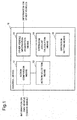
- Fig. 1 is a block diagram for illustrating a configuration of a control device 10 according to this example embodiment.
- the control device 10 includes an other vehicle information acquisition means 11, an action comparison means 12, an action selection means 13, an operation amount calculation means 14, and an operation setting means 15.
- the other vehicle information acquisition means 11 acquires information on states of the other vehicles from the communicable vehicles located in the vicinity of the one vehicle.
- the vicinity refers to within a predetermined range in the periphery of the one vehicle. While the other vehicle information acquisition means 11 of each vehicle communicates with the other vehicles located in the vicinity (within the predetermined range), information on each vehicle is mutually transmitted and received.
- the predetermined range may be set within a space having an outer periphery defined by a circle or a sphere, or may be set within a space having a deformable outer periphery.
- the other vehicle information acquisition means 11 acquires evaluation values of the actions of the plurality of unmanned vehicles as a whole (hereinafter, referred to as evaluation functions), or information associated with the evaluation functions.
- the evaluation functions are functions that are amounts regarding action purposes of the entire unmanned vehicles and are set for each of a plurality of kinds of actions.
- the plurality of kinds of actions include, for example, searching, chasing, and capturing of a search object, improvement of a communication situation with the other vehicles, and the like.
- the actions of the unmanned vehicles are not limited to the examples given here, and may be set in conformity with usage conditions of the unmanned vehicles.
- the action comparison means 12 acquires, from a sensor, a sensor signal related to a state of the one vehicle, such as a positional information, velocity, and an operation setting value of the one vehicle.
- the action comparison means 12 calculates comparison values for the plurality of actions to be taken by the one vehicle by using the acquired sensor signal, a setting value set for the one vehicle, and the information on the states of the other vehicles, which is acquired by the other vehicle information acquisition means 11.
- an example in which the action comparison means 12 calculates an evaluation function improvement degree as a comparison value based on the evaluation function value set for each vehicle is given.
- the action comparison means 12 For example, for each of the plurality of actions ("N" refers to the number for the actions), the action comparison means 12 generates an evaluation function A(N) for the operation amount of the one vehicle and evaluation functions B(N) for operation amounts of the other vehicles located in the vicinity, which are calculated based on the information on the states of the other vehicles located in the vicinity. Sequentially, the action comparison means 12 calculates an evaluation function improvement degree F(N) when the unmanned vehicle takes an action N by using the evaluation function A(N) and the evaluation functions B(N). Note that the evaluation function A(N) for the operation amount of the one vehicle is also referred to as a first evaluation function, and the evaluation functions B(N) for the operation amounts of the other vehicles in the vicinity are also referred to as second evaluation functions.
- the evaluation function A(N) and the evaluation functions B(N) are functions each indicating an amount by which the unmanned vehicle is intended to be controlled.
- functions each indicating the operation amount of the unmanned vehicle are assumed.
- the evaluation function improvement degree F(N) is obtained by, for example, calculating a difference between values of the evaluation functions or a difference between differentials of the evaluation functions with the value of the one vehicle as a reference.
- an example in which the differentials of the evaluation functions are used for obtaining the evaluation function improvement degree F(N) is given.
- the differentials of the evaluation functions are used, room for improvement of the evaluation functions can be evaluated directly regardless of absolute values of the evaluation functions.
- the action selection means 13 selects an action to be taken by the one vehicle, based on the comparison values of the plurality of kinds of actions, which are calculated by the action comparison means 12.
- the simplest function of the action selection means 13 is selecting an action, based on a magnitude correlation of the comparison values.
- the action selection means 13 selects an action having the largest evaluation function improvement degree F(N).
- the action selection means 13 may select the action by using a method other than the method of comparing the evaluation function improvement degrees F(N). For example, the action selection means 13 may select the action by performing comparison after multiplying the comparison value of each action by a weight factor. Further, when there is a correlation with another action, the action selection means 13 may perform comparison after forming an arithmetic expression using a value of the other action. In other words, the action selection means 13 selects the action by comparing the actions that the one vehicle may take by using some index.
- the operation amount calculation means 14 calculates the operation amount of the one vehicle by using the information on the action of the one vehicle, which is selected by the action selection means 13, and the information on the states of the other vehicles, which are acquired from the other vehicle information acquisition means 11.
- the operation amount calculation means 14 sets some rule for each action, and exercises the rule for the action selected by the action selection means 13. In this example embodiment, it is required to determine operation amounts of the group of unmanned vehicles for the selected action, besides an operation amount (also referred to as an action amount) of the single unmanned vehicle. Therefore, the operation amount calculation means 14 determines the operation amount for the selected action by using the information on the states of the other vehicles, which is acquired by the other vehicle information acquisition means 11.
- the operation amount calculation means 14 determines the operation amount by using the evaluation function.
- the evaluation function can be regarded as information indicating a state of the unmanned vehicle, and may be an index of an action standard as the group of unmanned vehicles (also referred to as a purpose of the group).
- the action as the group can be optimized.
- the operation setting means 15 sets an operation setting value of an actuator (not illustrated) for operating the one vehicle by using the calculation result acquired by the operation amount calculation means 14.
- the operation amount calculation means 14 performs specific processing in a case where the action of the unmanned vehicle is searching or chasing.
- evaluation functions for a search action and a chasing action can be set by maximizing a searching probability. This is equivalent to performing control of the group of unmanned vehicles with the purpose of the plurality of unmanned vehicles as a whole as the searching probability of the search object and performing control of maximizing the evaluation function value.
- the purpose of the plurality of unmanned vehicles as a whole is a value to be maximized with the entire group of unmanned vehicles, and is expressed with an evaluation function value.
- an area in which the group of unmanned vehicles is active (hereinafter, referred to as an active area) is divided into subareas, the number of which is the same as the number of the unmanned vehicles.
- a model having the following shape is used. More specifically, in the model, a center of the subarea divided for each unmanned vehicle is set as a peak, and the existence probability density is reduced toward a periphery of the subarea. In the entire active area, such evaluation functions having a plurality of peaks protruding upward are acquired.
- the action comparison means 12 calculates the evaluation functions (first and second evaluation functions) with a feature of a protruding shape.
- the operation amount calculation means 14 calculates the operation amount by using the evaluation functions with the feature of the protruding shape, which are calculated by the action comparison means 12.
- a model having the following shape is used as the evaluation function for chasing. More specifically, in the model, a position at which a search object is recently found is set as a peak, and the existence probability density is reduced as going away from the position of the search object. By setting the function as described above, the action of the unmanned vehicle is changed to chasing.
- a probability that each unmanned vehicle finds a search object (hereinafter, referred to as a finding probability) is expressed with Expression 2.
- ⁇ i indicates a searching effort provided to an unmanned vehicle i.
- the searching effort may be regarded as an operation amount.
- the finding probability is changed depending on an environment in which each unmanned vehicle is present. For example, it is known that the finding probability in a case where the search object is found by a sonar under the sea is expressed with Expression 3.
- p i 1 ⁇ e ⁇ ⁇ i ⁇ ⁇ i
- ⁇ i indicates an amount depending on radio wave propagation, i.e., an amount changed by a medium of a space in which the unmanned vehicle is present.
- a coefficient in Expression 3 it is desired that a value suitable for an environment in which the unmanned vehicle be always used.
- the searching probability of the search object for each unmanned vehicle can be expressed with a product of the existence probability density of the search object and the finding probability of the unmanned vehicle.
- x i , "y i ,” and “z i " each indicate a position coordinate of the unmanned vehicle i.
- f i g x i y i z i x t y t z t ⁇ p i ⁇ i
- a searching probability of the plurality of unmanned vehicles as a whole (also referred to as an overall searching probability) is expressed with Expression 5 in the following. ⁇ i g x i y i z i x t y t z t ⁇ p i ⁇ i
- the searching effort In consideration of energy of the unmanned vehicle, the searching effort needs to be considered to be finite. Therefore, the overall searching probability is maximized with respect to a fixed searching effort, which is put into the entire group of unmanned vehicles. In other words, the searching probability is increased as much as possible with respect to the finite searching effort.
- a searching effort ⁇ which is put into the entire group of unmanned vehicles per unit time, is set, and the searching probability is maximized based on the set searching effort ⁇ .
- the operation amount calculation means 14 determines an operation amount of each vehicle by calculating which of the unmanned vehicles are moved to what extent in order to maximize the search possibility of the plurality of unmanned vehicles as a whole with the above-mentioned finite searching effort as a whole. In other words, the operation amount calculation means 14 determines the operation amount of the one vehicle by solving the optimization problem under the constraint condition that a total sum of the searching efforts, which are put into the vehicles per unit time, is equivalent to the searching efforts, which are put into the entire group of unmanned vehicles per unit time.
- the evaluation value for the purpose of the plurality of unmanned vehicles as a whole is a value obtained by Expression 4.
- the information on the state, which is used additionally, is the positional information of the search object, the positional information of the unmanned vehicles, the searching effort, and the like.
- the operation amount calculation means 14 performs the above-mentioned formulation, and uses the following procedure in order to set the operation amount.
- the operation amount calculation means 14 determines the operation amount of the one vehicle by considering the states of the evaluation functions of the other vehicles located in the vicinity in order to maximize the searching probability per unit searching effort.
- the operation amount calculation means 14 determines to put the unit searching effort into the one vehicle in the following control step. In contrast, in a case where an increment of the searching probability of the one vehicle is smaller than those of the other vehicles in the vicinity, the operation amount calculation means 14 determines not to put the searching effort into the one vehicle in the following control step.
- the operation amount calculation means 14 is operated when the one vehicle has an increment of the searching probability larger than the other vehicles in the vicinity, whereas the operation amount calculation means 14 is not operated when the one vehicle has an increment of the searching probability smaller than the other vehicles in the vicinity.
- the searching probability per unit searching effort is equivalent to the differential of the evaluation function. Therefore, when repeating the operation of determining an operation amount in such a way that the searching probability per unit searching effort is increased to be maximum, the differentials of the evaluation functions are equal for all the unmanned vehicles. Thus, it is also effective to determine the operation amount in order to equalize the differentials of the evaluation functions.
- the unmanned vehicle when a certain unmanned vehicle is to determine the operation amount of the one vehicle, the unmanned vehicle is not required to acquire the state information of all the unmanned vehicles forming the group of unmanned vehicles, and can determine an operation amount close to the overall purpose by using only the state information of the adjacent unmanned vehicles.
- the operation setting value is required to be set as a vector quantity having three-dimensional directions, instead of a scalar quantity. Therefore, the operation setting means 15 distributes the operation amount, which is determined in the above-mentioned procedure, into outputs in three-dimensional directions, and sets a final operation setting value.
- the operation setting means 15 determines operation directions by taking the following procedure.
- the operation setting means 15 regards the current position of the unmanned vehicle as a starting point, and forms a vector connecting the starting point and the position of the search object.
- the operation setting means 15 unitizes the formed vector (standardization into a vector having a length of 1), and sets the unit vector as an operation vector.
- the length of the operation vector is set as the operation amount that is previously determined, the operation setting value for each direction can be acquired.
- the operation determination method in the case of searching in the area in which the unmanned vehicles are active or the case of chasing a certain object is as described above.
- an action in that a certain unmanned vehicle captures the object an action of improving a communication situation in such a way that the communication with other unmanned vehicles is not interrupted, and the like are exemplified.
- evaluation functions are set for those various actions similarly to the formulization for the action of searching, and an action is selected, the procedure of determining the operation setting value is executed similarly to the above-mentioned flow.
- the evaluation function may be set in such a way that the value is increased as the number of other communicable vehicles increases.
- the operation amount calculation means 14 can allocate an optimized action to each vehicle, and optimize and operate the allocated action as a group together with the other vehicles to which the same action is allocated.
- the operation amount of the unmanned vehicle which is calculated by the operation amount calculation means 14, is converted by the operation setting means 15 into the operation setting value for the actuator that actually moves the unmanned vehicle.
- the unmanned vehicle can perform the operation estimated by the operation amount calculation means 14.
- the actions of the group of unmanned vehicles as a whole can be optimized while each vehicle belonging to the group of unmanned vehicles selects an action autonomously.
- control device 10 According to this example embodiment, description is made of the control device 10 according to this example embodiment by providing application examples. In the following, with reference to the drawings, detailed description is made on a case where efficiency of searching and chasing is maximized based on the search probability while the plurality of unmanned vehicles switch the two kinds of actions including searching and chasing of the search object.
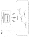
- Fig. 2 is a conceptual diagram for illustrating a system in an application example 1.
- a central control system 1 for controlling a plurality of unmanned vehicles 20 that are operated in a real space is constructed on a cloud.
- the plurality of unmanned vehicles 20 are controlled by the central control system 1 to which a plurality of control devices 10 according to this example embodiment are provided. Note that, in this application example, the above-mentioned procedure relating to the control device 10 is used.
- the unmanned vehicle 20 UAV: Unmanned Air Vehicle
- UUV Unmanned Undersea vehicle
- control device 10 corresponding to each unmanned vehicle 20 is disposed virtually on the cloud. Further, each control device 10 issues a control command to the unmanned vehicle 20 corresponding to the one vehicle while exchanging information with the virtual control devices 10 corresponding to the unmanned vehicles 20 in the vicinity as if the unmanned vehicle 20 exchanges the information with the unmanned vehicles 20 in the vicinity.
- the unmanned vehicle 20 takes two kinds of actions including searching of the search object in the active area and chasing of the search object found in the active area.
- the same expression as Expression 4 described above is set.
- a model which is formed of a plurality of Gaussian-type peaks.
- Each Gaussian-type peak is obtained by dividing the active area in which the group of unmanned vehicles is active by the number of the unmanned vehicles 20.
- the existence probability density is reduced toward the periphery from the peak, i.e., from the center of each divided subarea.
- the following Gaussian-type function is used. More specifically, in the Gaussian-type function, a position at which the search object is recently found is set as a peak, and the existence probability density is reduced as going away from the peak. Further, a finding possibility p; of each unmanned vehicle 20 is obtained with Expression 3.
- the other vehicle information acquisition means 11 uploads the positional information of a target captured by each unmanned vehicle 20 and the positional information of the one vehicle as appropriate as accompanying information that is used by the action comparison means 12 and the operation amount calculation means 14.
- the unmanned vehicles 20 are mutually operated in an asynchronous manner, and the uploaded information is also asynchronous. Even when the central control system 1 is provided on the cloud, all the information is asynchronous and is not gathered in the central control system 1 and therefore, a normal optimization calculation relating to the searching probability cannot be performed. Thus, in this application example, the entire group of unmanned vehicles is optimized by using the procedure described regarding the first example embodiment.
- Figs. 3 to 5 are conceptual diagrams in which actual operations of the unmanned vehicles 20 are placed in a chronological order.
- Fig. 3, Fig. 4 , and Fig. 5 are snapshots taken at a time t 1 , a time t 2 , and a time t 3 , respectively. Provided that the time period elapses in the order of the time t 1 , the time t 2 , and the time t 3 .
- An active area 100 is a space in which the unmanned vehicles 20 are supposed to be active. Note that, in Figs. 3 to 5 , the active area 100 is illustrated two-dimensionally, but the active area 100 has a three-dimensional spread in reality.
- the snapshot at the time t 1 indicates a state in which the search object is not yet detected.
- the unmanned vehicles 20 spread evenly throughout the active area 100, and take the action of searching.
- the snapshot at the time t 2 indicates a state in which a search object 300 is found after the time period elapses from the time t 1 to change the action of the unmanned vehicles 20 in the periphery of the search object 300 from searching to chasing.
- the unmanned vehicles 20 in a chasing region 200 which is surrounded by a closed curve of a broken line, switch to the action of chasing.
- the plurality of unmanned vehicles 20 located in the chasing region 200 takes the action of chasing in such a way as to surround the search object 300.
- the unmanned vehicles 20 outside the chasing region 200 continue searching in the active area 100 similarly at the time t 1 .
- the unmanned vehicles 20 spread substantially evenly.
- the snapshot at the time t 3 ( Fig. 5 ) indicates a state in which the number of unmanned vehicles 20, which switch the action from searching to chasing, is increased in conformity to movement of the search object 300, as compared to the situation at the time t 2 .
- the operation amount calculation means 14 determines the operation amount of each unmanned vehicle 20 in such a way as to efficiently increase the searching probability in chasing of the search object 300.
- the actions as the group can be switched appropriately according to a situation through the central control system disposed on the cloud, and the plurality of actions can be performed as the group.
- Fig. 6 is a conceptual diagram for illustrating a system in an application example 2.
- the control device 10 is mounted on each unmanned vehicle 20. Note that, in Fig. 6 , the control device 10 mounted on the unmanned vehicle 20 is omitted.
- each unmanned vehicle 20 exchanges the information with the communicable unmanned vehicles 20 located in the vicinity, and receives control from the control device 10 mounted on the one vehicle to take an action autonomously and dispersedly.
- this application example corresponds to a case where it is difficult to acquire the information from a field in which the group of unmanned vehicles is operated and where it is required to expect the group of unmanned vehicles to perform an autonomous and dispersive operation.
- this application example corresponds to a case where it is difficult to expect the central control system 1 or a case where the central control system 1 does not function.
- the other vehicle information acquisition means 11 is mounted on the unmanned vehicle 20, and exchanges the information on the search object 300 with the other vehicles located in the vicinity.
- the evaluation is performed by searching the search object 300 and switching the action to chasing when the search object 300 is found. As a result, an evaluation result similarly to that in the application example 1 is acquired.
- the central control system may be constructed as a special system.
- a control center in which the central control system is disposed may be built, and the unmanned vehicles may be controlled via the control center.
- the control center in which the central control system is disposed may be built on the shore to control a plurality of unmanned undersea vehicles (UUVs) or a plurality of unmanned surface vehicles (USVs).
- UUVs unmanned undersea vehicles
- USVs unmanned surface vehicles
- the plurality of UUVs or the plurality of USVs may be controlled by a mother ship on which the central control system is disposed.
- the control device according to this example embodiment is not limited to a UAV, a UUV, and a USV, and may be applied to any unmanned vehicles such as an aircraft type unmanned vehicle and a ground-running type unmanned vehicle.
- the control is performed in such a way as to maximize the searching probability, but the purpose and the value to be maximized are not limited to the searching probability and can be changed as appropriate.
- the method in this example embodiment can be also used for a case where a transceiver is mounted on each unmanned vehicle and where the unmanned vehicles are controlled to form a formation in such a way that information is transmitted throughout the widest range at a desired transfer rate.
- the method in this example embodiment is applicable to utilization where a plurality of unmanned vehicles have a certain purpose and where a certain value is maximized.
- description has been made on the example in which the two kinds of actions of searching and chasing are taken, but this example embodiment may be applied to three or more kinds of actions.
- Fig. 7 is a block diagram for illustrating a configuration of a control device 10-2 according to this embodiment.
- the control device 10-2 according to this example embodiment includes an object position estimation means 16. Note that, except for the object position estimation means 16, the control device 10-2 has a similar configuration to that of the control device 10 according to the first example embodiment.
- the object position estimation means 16 acquires information on the search object, which is found by other vehicles, from the other unmanned vehicle information acquisition means 11, and estimates a current position of the search object, based on a position at which the search object is recently found. Note that the object position estimation means 16 may estimate the current position of the search object, based on information on the search object, which is found with a sensor mounted on one vehicle, or may estimate the position of the search object by integrating information acquired by the one vehicle and the other vehicles. The object position estimation means 16 outputs the estimated position of the search object to the operation amount calculation means 14.
- the operation amount calculation means 14 estimates the existence probability density, and calculates an operation amount of the one vehicle similarly to the first example embodiment.
- the operation amount of the one vehicle can be calculated based on the current position of the search object.
- the actions of the group of unmanned vehicles as a whole can be optimized efficiently in a more realistic manner.
- a hardware configuration that achieves a control system of the control device according to this example embodiment by exemplifying a computer 90 in Fig. 8 as one example.
- the computer 90 in Fig. 8 is a configuration example for achieving the control device according to each of the example embodiments, and is not intended to limit the scope of the present invention.
- the computer 90 includes a processor 91, a main memory device 92, an auxiliary memory device 93, an input/output interface 95, and a communication interface 96.
- the interface is expressed as "I/F" in an abbreviated form.
- the processor 91, the main memory device 92, the auxiliary memory device 93, the input/output interface 95, and the communication interface 96 are connected to each other via a bus 99 in such a way as to enable mutual data communication.
- the processor 91, the main memory device 92, the auxiliary memory device 93, and the input/output interface 95 are connected to a network such as the Internet and the Intranet through the communication interface 96.
- the computer 90 is connected to a system or a device, which is arranged in a cloud, or the unmanned vehicle through the network.
- the processor 91 develops a program, which is stored in the auxiliary memory device 93 or the like, in the main memory device 92, and executes the developed program.
- This example embodiment may have a configuration using a software program installed in the computer 90.
- the processor 91 executes arithmetic processing and control processing which are executed by the control device according to this example embodiment.
- the main memory device 92 has a region in which the program is developed.
- the main memory device 92 may be a volatile memory such as a dynamic random access memory (DRAM), for example. Further, a nonvolatile memory such as a magnetoresistive random access memory (MRAM) may be configured or added as the main memory device 92.
- DRAM dynamic random access memory
- MRAM magnetoresistive random access memory
- the auxiliary memory device 93 is a means for storing various data.
- the auxiliary memory device 93 is configured by a local disc such as a hard disc and a flash memory. Note that the main memory device 92 may be configured to store the various data, and the auxiliary memory device 93 may be omitted.
- the input/output interface 95 is a device for connecting the computer 90 and peripherals to each other, based on connection standards of the computer 90 and the peripherals.
- the communication interface 96 is an interface for network connection such as the Internet and the Intranet, based on standards and specifications.
- the input/output interface 95 and the communication interface 96 may be shared as an interface for connecting to external devices.
- the computer 90 may be configured in such a way as to be connected with input units such as a keyboard, a mouse, and a touch panel as needed. Those input units are used for inputting information and setting. Note that, in a case where the touch panel is used as an input unit, a display screen of a display unit may have a configuration to also function as an interface of the input unit. Data communication between the processor 91 and the input unit may be performed through the input/output interface 95.
- the communication interface 96 is connected to an external system, a device, or the unmanned vehicle through the network.
- the computer 90 may be provided with a display unit for displaying information.
- the computer 90 it is preferred that the computer 90 be provided with a display control device (not illustrated) for controlling display of the display unit.
- the display unit may be connected to the computer 90 through the input/output interface 95.
- the computer 90 may be provided with a reader/writer as needed.
- the reader/writer is connected to the bus 99.
- the reader/writer mediates reading of data and a program from the recording medium, writing of processing results from the computer 90 to the recording medium, and the like.
- the recording medium may be achieved by a semiconductor recording medium such as a secure digital (SD) card and a universal serial bus (USB) memory, and the like.
- the recording medium may be achieved by a magnetic recording medium such as a flexible disc, an optical recording medium such as a compact disc (CD) and a digital versatile disc (DVD), and other recording media.
- the hardware configuration for enabling the control device according to the example embodiment of the present invention is thus given above as one example.
- the hardware configuration in Fig. 8 is merely an example of the hardware configuration for enabling the control device according to this example embodiment, and is not intended to limit the scope of the present invention.
- a control program which causes a computer to execute processing related to the control device according to this example embodiment, is also included in the scope of the present invention.
- a program recording medium that records the control program according to the example embodiment of the present invention is also included in the scope of the present invention.
Applications Claiming Priority (2)
| Application Number | Priority Date | Filing Date | Title |
|---|---|---|---|
| JP2016237840 | 2016-12-07 | ||
| PCT/JP2017/043613 WO2018105599A1 (fr) | 2016-12-07 | 2017-12-05 | Système et procédé de commande, et support d'enregistrement de programme |
Publications (3)
| Publication Number | Publication Date |
|---|---|
| EP3553622A1 true EP3553622A1 (fr) | 2019-10-16 |
| EP3553622A4 EP3553622A4 (fr) | 2019-12-04 |
| EP3553622B1 EP3553622B1 (fr) | 2021-03-24 |
Family
ID=62491296
Family Applications (1)
| Application Number | Title | Priority Date | Filing Date |
|---|---|---|---|
| EP17878748.7A Active EP3553622B1 (fr) | 2016-12-07 | 2017-12-05 | Système et procédé de commande, et support d'enregistrement de programme |
Country Status (4)
| Country | Link |
|---|---|
| US (1) | US11163299B2 (fr) |
| EP (1) | EP3553622B1 (fr) |
| JP (1) | JP7056580B2 (fr) |
| WO (1) | WO2018105599A1 (fr) |
Cited By (1)
| Publication number | Priority date | Publication date | Assignee | Title |
|---|---|---|---|---|
| CN111694365A (zh) * | 2020-07-01 | 2020-09-22 | 武汉理工大学 | 一种基于深度强化学习的无人船艇编队路径跟踪方法 |
Families Citing this family (11)
| Publication number | Priority date | Publication date | Assignee | Title |
|---|---|---|---|---|
| JP7091723B2 (ja) * | 2018-03-07 | 2022-06-28 | 株式会社豊田中央研究所 | 制御装置、移動体、自律分散制御プログラム |
| JP7317436B2 (ja) * | 2018-08-02 | 2023-07-31 | 株式会社国際電気通信基礎技術研究所 | ロボット、ロボット制御プログラムおよびロボット制御方法 |
| JP6761146B1 (ja) * | 2018-11-22 | 2020-09-23 | 楽天株式会社 | 情報処理システム、情報処理方法及びプログラム |
| WO2020136850A1 (fr) * | 2018-12-27 | 2020-07-02 | 日本電気株式会社 | Dispositif de commande, dispositif de détermination de formation, procédé de commande et programme |
| JP6678831B1 (ja) * | 2019-03-12 | 2020-04-08 | 三菱電機株式会社 | 制御装置および制御方法 |
| US11960277B2 (en) | 2019-03-20 | 2024-04-16 | Nec Corporation | Unmanned vehicle controlling system and method, and nontransitory computer-readable medium |
| WO2021024352A1 (fr) * | 2019-08-05 | 2021-02-11 | 三菱電機株式会社 | Dispositif de commande et procédé de commande |
| JP7308104B2 (ja) | 2019-08-30 | 2023-07-13 | 三菱重工業株式会社 | 無人機協調システム、無人機協調処理方法及びプログラム |
| WO2021095189A1 (fr) * | 2019-11-14 | 2021-05-20 | 日本電気株式会社 | Dispositif de commande de véhicule sans pilote, système de commande de véhicule sans pilote, procédé de commande de véhicule sans pilote et support d'enregistrement |
| JP7366410B2 (ja) | 2020-01-16 | 2023-10-23 | 学校法人 関西大学 | 移動体、無線通信システム、移動体の制御方法、および制御プログラム |
| CN112612212B (zh) * | 2020-12-30 | 2021-11-23 | 上海大学 | 一种异构多无人系统编队与协同目标驱离方法 |
Family Cites Families (15)
| Publication number | Priority date | Publication date | Assignee | Title |
|---|---|---|---|---|
| JPS4926958B1 (fr) | 1970-12-28 | 1974-07-13 | ||
| JP3732292B2 (ja) * | 1996-11-27 | 2006-01-05 | 本田技研工業株式会社 | 車群走行制御システム |
| CA2514523C (fr) | 2003-02-03 | 2011-05-31 | Kiva Systems, Inc. | Systeme de manipulation de materiaux et procedes d'utilisation d'unites d'entrainement mobiles autonomes et de plateaux d'inventaire mobiles |
| US8086351B2 (en) | 2004-02-06 | 2011-12-27 | Icosystem Corporation | Methods and systems for area search using a plurality of unmanned vehicles |
| US7908040B2 (en) | 2004-07-15 | 2011-03-15 | Raytheon Company | System and method for automated search by distributed elements |
| US9026315B2 (en) * | 2010-10-13 | 2015-05-05 | Deere & Company | Apparatus for machine coordination which maintains line-of-site contact |
| JP5271772B2 (ja) | 2009-03-30 | 2013-08-21 | 株式会社日立製作所 | 列車運行制御方法および車上制御装置 |
| US8634982B2 (en) | 2009-08-19 | 2014-01-21 | Raytheon Company | System and method for resource allocation and management |
| JP5559671B2 (ja) | 2010-12-13 | 2014-07-23 | 公益財団法人鉄道総合技術研究所 | 走行制御支援方法及び走行制御支援装置 |
| US9104201B1 (en) | 2012-02-13 | 2015-08-11 | C&P Technologies, Inc. | Method and apparatus for dynamic swarming of airborne drones for a reconfigurable array |
| JP6207908B2 (ja) | 2012-11-29 | 2017-10-04 | 三菱重工業株式会社 | 航空機管理装置、航空機、及び航空機管理方法 |
| US11188096B2 (en) * | 2015-04-16 | 2021-11-30 | Nec Corporation | Control apparatus, control method, and storage medium |
| DE112017001267B4 (de) * | 2016-03-11 | 2024-05-02 | Panasonic Automotive Systems Co., Ltd. | Automatikfahrzeug-Dispatchingsystem und Servervorrichtung |
| JP7044061B2 (ja) * | 2016-06-21 | 2022-03-30 | 日本電気株式会社 | 移動体、移動体制御システム、移動体制御方法、インターフェース装置、およびプログラム |
| US10663595B2 (en) * | 2017-03-29 | 2020-05-26 | Luminar Technologies, Inc. | Synchronized multiple sensor head system for a vehicle |
-
2017
- 2017-12-05 JP JP2018555007A patent/JP7056580B2/ja active Active
- 2017-12-05 EP EP17878748.7A patent/EP3553622B1/fr active Active
- 2017-12-05 WO PCT/JP2017/043613 patent/WO2018105599A1/fr unknown
- 2017-12-05 US US16/463,464 patent/US11163299B2/en active Active
Cited By (2)
| Publication number | Priority date | Publication date | Assignee | Title |
|---|---|---|---|---|
| CN111694365A (zh) * | 2020-07-01 | 2020-09-22 | 武汉理工大学 | 一种基于深度强化学习的无人船艇编队路径跟踪方法 |
| CN111694365B (zh) * | 2020-07-01 | 2021-04-20 | 武汉理工大学 | 一种基于深度强化学习的无人船艇编队路径跟踪方法 |
Also Published As
| Publication number | Publication date |
|---|---|
| JPWO2018105599A1 (ja) | 2019-11-07 |
| US20190354113A1 (en) | 2019-11-21 |
| EP3553622A4 (fr) | 2019-12-04 |
| WO2018105599A1 (fr) | 2018-06-14 |
| EP3553622B1 (fr) | 2021-03-24 |
| JP7056580B2 (ja) | 2022-04-19 |
| US11163299B2 (en) | 2021-11-02 |
Similar Documents
| Publication | Publication Date | Title |
|---|---|---|
| EP3553622B1 (fr) | Système et procédé de commande, et support d'enregistrement de programme | |
| Lolla et al. | Time-optimal path planning in dynamic flows using level set equations: theory and schemes | |
| Yang et al. | Multi-UAV cooperative search using an opportunistic learning method | |
| JP6869230B2 (ja) | 物体を認識する方法およびシステム | |
| JP6750615B2 (ja) | 制御装置、機器、情報処理システム、制御方法、および、制御プログラム | |
| JP2018505788A (ja) | 専用ロボットの動作を計画するハードウェアならびにその作製方法および使用方法 | |
| Herman et al. | Inverse reinforcement learning of behavioral models for online-adapting navigation strategies | |
| US11253997B2 (en) | Method for tracking multiple target objects, device, and computer program for implementing the tracking of multiple target objects for the case of moving objects | |
| Wang et al. | Underwater localization and environment mapping using wireless robots | |
| CN105389855A (zh) | 对对象进行建模的方法和设备 | |
| Ferrari et al. | A potential field approach to finding minimum-exposure paths in wireless sensor networks | |
| Mannucci et al. | Autonomous 3D exploration of large areas: A cooperative frontier-based approach | |
| Shriyam et al. | Decomposition of collaborative surveillance tasks for execution in marine environments by a team of unmanned surface vehicles | |
| Sun et al. | Distributed probabilistic search and tracking of agile mobile ground targets using a network of unmanned aerial vehicles | |
| Papatheodorou et al. | Distributed area coverage control with imprecise robot localization | |
| McMahon et al. | Autonomous underwater vehicle mine countermeasures mission planning via the physical traveling salesman problem | |
| Haugen et al. | Monitoring an advection-diffusion process using aerial mobile sensors | |
| Pham et al. | A multi-robot, cooperative, and active slam algorithm for exploration | |
| JP7070673B2 (ja) | 自律動作機の制御装置、自律動作機の制御方法、及び、自律動作機の制御プログラム | |
| Morelli et al. | Integrated mapping and path planning for very large-scale robotic (vlsr) systems | |
| Mohandes et al. | A motion planning scheme for automated wildfire suppression | |
| Xidias et al. | Path planning for formation control of autonomous vehicles | |
| EP3543816B1 (fr) | Système de commande, procédé de commande et programme | |
| Zambom et al. | Constrained optimization with stochastic feasibility regions applied to vehicle path planning | |
| Al-Ansarry et al. | An Efficient Path Planning in Uncertainty Environments using Dynamic Grid-Based and Potential Field Methods. |
Legal Events
| Date | Code | Title | Description |
|---|---|---|---|
| STAA | Information on the status of an ep patent application or granted ep patent |
Free format text: STATUS: THE INTERNATIONAL PUBLICATION HAS BEEN MADE |
|
| PUAI | Public reference made under article 153(3) epc to a published international application that has entered the european phase |
Free format text: ORIGINAL CODE: 0009012 |
|
| STAA | Information on the status of an ep patent application or granted ep patent |
Free format text: STATUS: REQUEST FOR EXAMINATION WAS MADE |
|
| 17P | Request for examination filed |
Effective date: 20190708 |
|
| AK | Designated contracting states |
Kind code of ref document: A1 Designated state(s): AL AT BE BG CH CY CZ DE DK EE ES FI FR GB GR HR HU IE IS IT LI LT LU LV MC MK MT NL NO PL PT RO RS SE SI SK SM TR |
|
| AX | Request for extension of the european patent |
Extension state: BA ME |
|
| A4 | Supplementary search report drawn up and despatched |
Effective date: 20191031 |
|
| RIC1 | Information provided on ipc code assigned before grant |
Ipc: G05D 1/02 20060101ALI20191025BHEP Ipc: G05D 1/10 20060101AFI20191025BHEP Ipc: G08G 1/00 20060101ALI20191025BHEP Ipc: B64C 39/02 20060101ALI20191025BHEP Ipc: G08G 1/09 20060101ALI20191025BHEP Ipc: F41H 13/00 20060101ALI20191025BHEP Ipc: G05D 1/00 20060101ALI20191025BHEP Ipc: G08G 1/16 20060101ALI20191025BHEP Ipc: B64C 19/02 20060101ALI20191025BHEP |
|
| DAV | Request for validation of the european patent (deleted) | ||
| DAX | Request for extension of the european patent (deleted) | ||
| GRAP | Despatch of communication of intention to grant a patent |
Free format text: ORIGINAL CODE: EPIDOSNIGR1 |
|
| STAA | Information on the status of an ep patent application or granted ep patent |
Free format text: STATUS: GRANT OF PATENT IS INTENDED |
|
| INTG | Intention to grant announced |
Effective date: 20201112 |
|
| GRAS | Grant fee paid |
Free format text: ORIGINAL CODE: EPIDOSNIGR3 |
|
| GRAA | (expected) grant |
Free format text: ORIGINAL CODE: 0009210 |
|
| STAA | Information on the status of an ep patent application or granted ep patent |
Free format text: STATUS: THE PATENT HAS BEEN GRANTED |
|
| AK | Designated contracting states |
Kind code of ref document: B1 Designated state(s): AL AT BE BG CH CY CZ DE DK EE ES FI FR GB GR HR HU IE IS IT LI LT LU LV MC MK MT NL NO PL PT RO RS SE SI SK SM TR |
|
| REG | Reference to a national code |
Ref country code: GB Ref legal event code: FG4D |
|
| REG | Reference to a national code |
Ref country code: CH Ref legal event code: EP |
|
| REG | Reference to a national code |
Ref country code: DE Ref legal event code: R096 Ref document number: 602017035462 Country of ref document: DE |
|
| REG | Reference to a national code |
Ref country code: IE Ref legal event code: FG4D |
|
| REG | Reference to a national code |
Ref country code: AT Ref legal event code: REF Ref document number: 1375122 Country of ref document: AT Kind code of ref document: T Effective date: 20210415 |
|
| REG | Reference to a national code |
Ref country code: LT Ref legal event code: MG9D |
|
| PG25 | Lapsed in a contracting state [announced via postgrant information from national office to epo] |
Ref country code: GR Free format text: LAPSE BECAUSE OF FAILURE TO SUBMIT A TRANSLATION OF THE DESCRIPTION OR TO PAY THE FEE WITHIN THE PRESCRIBED TIME-LIMIT Effective date: 20210625 Ref country code: FI Free format text: LAPSE BECAUSE OF FAILURE TO SUBMIT A TRANSLATION OF THE DESCRIPTION OR TO PAY THE FEE WITHIN THE PRESCRIBED TIME-LIMIT Effective date: 20210324 Ref country code: HR Free format text: LAPSE BECAUSE OF FAILURE TO SUBMIT A TRANSLATION OF THE DESCRIPTION OR TO PAY THE FEE WITHIN THE PRESCRIBED TIME-LIMIT Effective date: 20210324 Ref country code: NO Free format text: LAPSE BECAUSE OF FAILURE TO SUBMIT A TRANSLATION OF THE DESCRIPTION OR TO PAY THE FEE WITHIN THE PRESCRIBED TIME-LIMIT Effective date: 20210624 Ref country code: BG Free format text: LAPSE BECAUSE OF FAILURE TO SUBMIT A TRANSLATION OF THE DESCRIPTION OR TO PAY THE FEE WITHIN THE PRESCRIBED TIME-LIMIT Effective date: 20210624 |
|
| PG25 | Lapsed in a contracting state [announced via postgrant information from national office to epo] |
Ref country code: LV Free format text: LAPSE BECAUSE OF FAILURE TO SUBMIT A TRANSLATION OF THE DESCRIPTION OR TO PAY THE FEE WITHIN THE PRESCRIBED TIME-LIMIT Effective date: 20210324 Ref country code: RS Free format text: LAPSE BECAUSE OF FAILURE TO SUBMIT A TRANSLATION OF THE DESCRIPTION OR TO PAY THE FEE WITHIN THE PRESCRIBED TIME-LIMIT Effective date: 20210324 Ref country code: SE Free format text: LAPSE BECAUSE OF FAILURE TO SUBMIT A TRANSLATION OF THE DESCRIPTION OR TO PAY THE FEE WITHIN THE PRESCRIBED TIME-LIMIT Effective date: 20210324 |
|
| REG | Reference to a national code |
Ref country code: NL Ref legal event code: MP Effective date: 20210324 |
|
| REG | Reference to a national code |
Ref country code: AT Ref legal event code: MK05 Ref document number: 1375122 Country of ref document: AT Kind code of ref document: T Effective date: 20210324 |
|
| PG25 | Lapsed in a contracting state [announced via postgrant information from national office to epo] |
Ref country code: NL Free format text: LAPSE BECAUSE OF FAILURE TO SUBMIT A TRANSLATION OF THE DESCRIPTION OR TO PAY THE FEE WITHIN THE PRESCRIBED TIME-LIMIT Effective date: 20210324 |
|
| PG25 | Lapsed in a contracting state [announced via postgrant information from national office to epo] |
Ref country code: SM Free format text: LAPSE BECAUSE OF FAILURE TO SUBMIT A TRANSLATION OF THE DESCRIPTION OR TO PAY THE FEE WITHIN THE PRESCRIBED TIME-LIMIT Effective date: 20210324 Ref country code: AT Free format text: LAPSE BECAUSE OF FAILURE TO SUBMIT A TRANSLATION OF THE DESCRIPTION OR TO PAY THE FEE WITHIN THE PRESCRIBED TIME-LIMIT Effective date: 20210324 Ref country code: LT Free format text: LAPSE BECAUSE OF FAILURE TO SUBMIT A TRANSLATION OF THE DESCRIPTION OR TO PAY THE FEE WITHIN THE PRESCRIBED TIME-LIMIT Effective date: 20210324 Ref country code: CZ Free format text: LAPSE BECAUSE OF FAILURE TO SUBMIT A TRANSLATION OF THE DESCRIPTION OR TO PAY THE FEE WITHIN THE PRESCRIBED TIME-LIMIT Effective date: 20210324 Ref country code: EE Free format text: LAPSE BECAUSE OF FAILURE TO SUBMIT A TRANSLATION OF THE DESCRIPTION OR TO PAY THE FEE WITHIN THE PRESCRIBED TIME-LIMIT Effective date: 20210324 |
|
| PG25 | Lapsed in a contracting state [announced via postgrant information from national office to epo] |
Ref country code: IS Free format text: LAPSE BECAUSE OF FAILURE TO SUBMIT A TRANSLATION OF THE DESCRIPTION OR TO PAY THE FEE WITHIN THE PRESCRIBED TIME-LIMIT Effective date: 20210724 Ref country code: PT Free format text: LAPSE BECAUSE OF FAILURE TO SUBMIT A TRANSLATION OF THE DESCRIPTION OR TO PAY THE FEE WITHIN THE PRESCRIBED TIME-LIMIT Effective date: 20210726 Ref country code: PL Free format text: LAPSE BECAUSE OF FAILURE TO SUBMIT A TRANSLATION OF THE DESCRIPTION OR TO PAY THE FEE WITHIN THE PRESCRIBED TIME-LIMIT Effective date: 20210324 Ref country code: SK Free format text: LAPSE BECAUSE OF FAILURE TO SUBMIT A TRANSLATION OF THE DESCRIPTION OR TO PAY THE FEE WITHIN THE PRESCRIBED TIME-LIMIT Effective date: 20210324 Ref country code: RO Free format text: LAPSE BECAUSE OF FAILURE TO SUBMIT A TRANSLATION OF THE DESCRIPTION OR TO PAY THE FEE WITHIN THE PRESCRIBED TIME-LIMIT Effective date: 20210324 |
|
| REG | Reference to a national code |
Ref country code: DE Ref legal event code: R097 Ref document number: 602017035462 Country of ref document: DE |
|
| PG25 | Lapsed in a contracting state [announced via postgrant information from national office to epo] |
Ref country code: ES Free format text: LAPSE BECAUSE OF FAILURE TO SUBMIT A TRANSLATION OF THE DESCRIPTION OR TO PAY THE FEE WITHIN THE PRESCRIBED TIME-LIMIT Effective date: 20210324 Ref country code: AL Free format text: LAPSE BECAUSE OF FAILURE TO SUBMIT A TRANSLATION OF THE DESCRIPTION OR TO PAY THE FEE WITHIN THE PRESCRIBED TIME-LIMIT Effective date: 20210324 Ref country code: DK Free format text: LAPSE BECAUSE OF FAILURE TO SUBMIT A TRANSLATION OF THE DESCRIPTION OR TO PAY THE FEE WITHIN THE PRESCRIBED TIME-LIMIT Effective date: 20210324 |
|
| PLBE | No opposition filed within time limit |
Free format text: ORIGINAL CODE: 0009261 |
|
| STAA | Information on the status of an ep patent application or granted ep patent |
Free format text: STATUS: NO OPPOSITION FILED WITHIN TIME LIMIT |
|
| PG25 | Lapsed in a contracting state [announced via postgrant information from national office to epo] |
Ref country code: SI Free format text: LAPSE BECAUSE OF FAILURE TO SUBMIT A TRANSLATION OF THE DESCRIPTION OR TO PAY THE FEE WITHIN THE PRESCRIBED TIME-LIMIT Effective date: 20210324 |
|
| 26N | No opposition filed |
Effective date: 20220104 |
|
| PG25 | Lapsed in a contracting state [announced via postgrant information from national office to epo] |
Ref country code: IS Free format text: LAPSE BECAUSE OF FAILURE TO SUBMIT A TRANSLATION OF THE DESCRIPTION OR TO PAY THE FEE WITHIN THE PRESCRIBED TIME-LIMIT Effective date: 20210724 |
|
| PG25 | Lapsed in a contracting state [announced via postgrant information from national office to epo] |
Ref country code: MC Free format text: LAPSE BECAUSE OF FAILURE TO SUBMIT A TRANSLATION OF THE DESCRIPTION OR TO PAY THE FEE WITHIN THE PRESCRIBED TIME-LIMIT Effective date: 20210324 |
|
| REG | Reference to a national code |
Ref country code: CH Ref legal event code: PL |
|
| REG | Reference to a national code |
Ref country code: BE Ref legal event code: MM Effective date: 20211231 |
|
| PG25 | Lapsed in a contracting state [announced via postgrant information from national office to epo] |
Ref country code: LU Free format text: LAPSE BECAUSE OF NON-PAYMENT OF DUE FEES Effective date: 20211205 Ref country code: IE Free format text: LAPSE BECAUSE OF NON-PAYMENT OF DUE FEES Effective date: 20211205 |
|
| PG25 | Lapsed in a contracting state [announced via postgrant information from national office to epo] |
Ref country code: BE Free format text: LAPSE BECAUSE OF NON-PAYMENT OF DUE FEES Effective date: 20211231 |
|
| PG25 | Lapsed in a contracting state [announced via postgrant information from national office to epo] |
Ref country code: LI Free format text: LAPSE BECAUSE OF NON-PAYMENT OF DUE FEES Effective date: 20211231 Ref country code: CH Free format text: LAPSE BECAUSE OF NON-PAYMENT OF DUE FEES Effective date: 20211231 |
|
| PG25 | Lapsed in a contracting state [announced via postgrant information from national office to epo] |
Ref country code: IT Free format text: LAPSE BECAUSE OF FAILURE TO SUBMIT A TRANSLATION OF THE DESCRIPTION OR TO PAY THE FEE WITHIN THE PRESCRIBED TIME-LIMIT Effective date: 20210324 |
|
| PG25 | Lapsed in a contracting state [announced via postgrant information from national office to epo] |
Ref country code: CY Free format text: LAPSE BECAUSE OF FAILURE TO SUBMIT A TRANSLATION OF THE DESCRIPTION OR TO PAY THE FEE WITHIN THE PRESCRIBED TIME-LIMIT Effective date: 20210324 |
|
| PG25 | Lapsed in a contracting state [announced via postgrant information from national office to epo] |
Ref country code: HU Free format text: LAPSE BECAUSE OF FAILURE TO SUBMIT A TRANSLATION OF THE DESCRIPTION OR TO PAY THE FEE WITHIN THE PRESCRIBED TIME-LIMIT; INVALID AB INITIO Effective date: 20171205 |
|
| REG | Reference to a national code |
Ref country code: DE Ref legal event code: R079 Ref document number: 602017035462 Country of ref document: DE Free format text: PREVIOUS MAIN CLASS: G05D0001100000 Ipc: G05D0001460000 |
|
| PGFP | Annual fee paid to national office [announced via postgrant information from national office to epo] |
Ref country code: GB Payment date: 20231220 Year of fee payment: 7 |
|
| PGFP | Annual fee paid to national office [announced via postgrant information from national office to epo] |
Ref country code: FR Payment date: 20231222 Year of fee payment: 7 Ref country code: DE Payment date: 20231214 Year of fee payment: 7 |
|
| PG25 | Lapsed in a contracting state [announced via postgrant information from national office to epo] |
Ref country code: MK Free format text: LAPSE BECAUSE OF FAILURE TO SUBMIT A TRANSLATION OF THE DESCRIPTION OR TO PAY THE FEE WITHIN THE PRESCRIBED TIME-LIMIT Effective date: 20210324 |