EP3553536B1 - Combination of a sensor module and a fuse, and use of a sensor module in the combination - Google Patents
Combination of a sensor module and a fuse, and use of a sensor module in the combination Download PDFInfo
- Publication number
- EP3553536B1 EP3553536B1 EP18167271.8A EP18167271A EP3553536B1 EP 3553536 B1 EP3553536 B1 EP 3553536B1 EP 18167271 A EP18167271 A EP 18167271A EP 3553536 B1 EP3553536 B1 EP 3553536B1
- Authority
- EP
- European Patent Office
- Prior art keywords
- sensor module
- fuse
- current sensor
- current
- data
- Prior art date
- Legal status (The legal status is an assumption and is not a legal conclusion. Google has not performed a legal analysis and makes no representation as to the accuracy of the status listed.)
- Revoked
Links
Images

Classifications
-
- G—PHYSICS
- G01—MEASURING; TESTING
- G01R—MEASURING ELECTRIC VARIABLES; MEASURING MAGNETIC VARIABLES
- G01R15/00—Details of measuring arrangements of the types provided for in groups G01R17/00 - G01R29/00, G01R33/00 - G01R33/26 or G01R35/00
- G01R15/14—Adaptations providing voltage or current isolation, e.g. for high-voltage or high-current networks
- G01R15/142—Arrangements for simultaneous measurements of several parameters employing techniques covered by groups G01R15/14 - G01R15/26
-
- G—PHYSICS
- G01—MEASURING; TESTING
- G01R—MEASURING ELECTRIC VARIABLES; MEASURING MAGNETIC VARIABLES
- G01R19/00—Arrangements for measuring currents or voltages or for indicating presence or sign thereof
- G01R19/25—Arrangements for measuring currents or voltages or for indicating presence or sign thereof using digital measurement techniques
- G01R19/2513—Arrangements for monitoring electric power systems, e.g. power lines or loads; Logging
-
- H—ELECTRICITY
- H01—ELECTRIC ELEMENTS
- H01H—ELECTRIC SWITCHES; RELAYS; SELECTORS; EMERGENCY PROTECTIVE DEVICES
- H01H85/00—Protective devices in which the current flows through a part of fusible material and this current is interrupted by displacement of the fusible material when this current becomes excessive
- H01H85/02—Details
- H01H85/0241—Structural association of a fuse and another component or apparatus
- H01H2085/0266—Structural association with a measurement device, e.g. a shunt
-
- H—ELECTRICITY
- H01—ELECTRIC ELEMENTS
- H01H—ELECTRIC SWITCHES; RELAYS; SELECTORS; EMERGENCY PROTECTIVE DEVICES
- H01H85/00—Protective devices in which the current flows through a part of fusible material and this current is interrupted by displacement of the fusible material when this current becomes excessive
- H01H85/02—Details
- H01H85/04—Fuses, i.e. expendable parts of the protective device, e.g. cartridges
- H01H85/05—Component parts thereof
- H01H85/143—Electrical contacts; Fastening fusible members to such contacts
- H01H85/153—Knife-blade-end contacts
Definitions
- the present invention relates to a combination of a current sensor module for measuring an electric current through an electrical conductor and a fuse according to claim 1, and a use according to claim 2.
- Such sensors and measuring devices have the property that a separate sensor or device must be used for measuring the desired properties. A user must also be at the location of the measurement.
- a drawback of the fact that one has to check the information personally is that there are many man hours with correspondingly high costs.
- the invention is defined by the independent claims and now aims to provide a combination according to claim 1 and a use according to claim 2, wherein the sensor module is an improved sensor module
- the invention also aims to include a sensor module with which an automatic measurement of desired properties can be carried out.
- Another object of the invention is to include a sensor module with which a series of measurement data obtained in the past remains available for use, management and processing.
- Another object of the invention is to provide a combination of a fuse and a sensor module according to the invention.
- the invention relates to a combination of a current sensor module and a fuse according to claim 1. Furthermore, it can transmit measurement data to a receiver which stores the data. This provides the advantage that in case of an incident, it can be checked at any time which properties or characteristics the electric current through the conductor had prior to the incident.
- this provides the advantage that the measurement data are available for later use, management, analysis or processing, so that the user can obtain much more information from the measurement data than originally was possible and the goal for a temporary measurement which was performed by a user on location.
- the sensor module used in the invention does not require separate energy supply.
- the current flowing through the conductor is sufficient to supply the sensor, as necessary.
- the invention therefore relates to a combination of a current sensor module, for measuring an electric current through an electrical conductor, and a fuse, the current sensor module comprising a sensor for measuring the current strength of the electrical current flowing through the conductor, wherein the current sensor module further comprises a transmitter configured to transmit current strength data measured by the sensor to a receiver of a data collecting device wherein the current sensor module is adapted for combination with the fuse protecting the electrical conductor against overload, wherein the current sensor module is placed in a housing comprising a through hole through which one terminal extending from the housing of the fuse is inserted, and wherein the current sensor module and the fuse each have their own housing.
- This current sensor module provides the effect that data of the electric current through the conductor can be measured in a simple manner. As a result, at any time it is not only possible to check what the conditions were at the time of a failure of the fuse, but also to carry out a continuous analysis of the electricity network.
- the combination according to the invention is of a standardized size, so that it can easily be used.
- a simple possibility is obtained to continuously collect data of the electrical current through the conductor.
- the total external dimension of the new sensor module and the fuse used which collectively contains both the sensor and the transmitter and the current-interrupting part serving as a fuse, must be equal to the outer dimension of a fuse according to the state-of-the-art.
- the one of the terminals being embodied to be received in the through hole to superpose the housing of the current sensor module and the housing of the fuse, wherein the lengths of said terminals extending from the current sensor module housing and the fuse housing, after placement of the current sensor module on the one terminal, are substantially equal.
- WO2017/098021A1 teaches a housing incorporating the fuse, a current sensing device, a microprocessor 33 and a communication module.
- US2017/059640A1 describes a monitoring system.
- WO 2017/078525 describes a system for monitoring electric current in a network comprising at least one electrical fuse.
- US2013/024139A1 comprises two electrical connectors for connecting the current sensor to the portion of the electrical system, such that there is a direct, physical connection of the sensor with the electrical system.
- the invention relates to the use of the current sensor module in the combination according to the present invention for measuring the electric current through the electrical conductor, the current sensor module comprising the sensor for measuring the current strength of the electrical current flowing through the conductor, wherein the current sensor module further comprises the transmitter for transmitting current strength data measured by the sensor to the receiver of the data collecting device, wherein the current sensor module is adapted for combination with the fuse which is designed for protecting the electrical conductor against overload, wherein the current sensor module is placed in the housing comprising the through hole through which the one terminal extending from the housing of the fuse is inserted, wherein the fuse comprises two protruding terminals at opposite sides of the housing of the fuse, one of which terminals being embodied to be received in the through hole wherein the lengths of said terminals extending from the current sensor module housing and the fuse housing, after placement of the current sensor module on the one terminal, are substantially equal.
- the current sensor module comprises a sensor for measuring the current strength.
- the sensor module further comprises a sensor for measuring the temperature.
- the current sensor module further comprises a transmitter for transmitting data measured by the sensor to a receiver of a data collecting device.
- a transmitter for transmitting data measured by the sensor to a receiver of a data collecting device.
- the sensor module according to the invention also comprises a receiver in connection with carrying out software updates or the like of the electronics in the sensor module used in the invention. This can be a software update for the sensor part, but also for other components that are included in the sensor module.
- the communication device in the sensor module used in the invention will usually be a transmitter / receiver. However, it is possible to design the sensor module used in the invention with only one transmitter, with which an effective embodiment of the invention is obtained. However, preference is given to a combined transmitter / receiver.
- a sensor may be present at the current conductors for measuring the voltage in the conductors.
- the current sensor module comprises a coil for co-operation with electrical alternating current flowing through the conductor for feeding the sensor, the transmitter and optional other electronic components.
- a capacitor or supercap will also be able to be present as a backup power supply to provide a backup supply, which is particularly important for transmitting measurement data which have been obtained prior to a failure of a fuse, which is meant to be an interruption of the conductor and that had not yet been sent to the receiver.
- a suitable application of the sensor module used in the present invention is found in a combination with a blade fuse, the through hole being configured for receiving one blade.
- This is for example used in distribution boxes in city districts and the like.
- the invention is certainly not limited to a blade fuse.
- the invention can also be used, for example, in rail fuses with terminals in the rail as used in distribution boxes in Great Britain.
- a combination as mentioned before comprising a further combination of the current sensor module and the data collecting device, the data collecting device comprising the receiver for receiving data transmitted by the transmitter of the current sensor module.
- the data collecting device comprising a receiver for receiving data transmitted by the transmitter of the current sensor module.
- the contents of the memory of the data collecting device can suitably be retrieved by a user when the data collecting device comprises a communication device for exchanging data with a user for consideration, storage, analysis or process of the data.
- the transmitter can be both wireless and wired.
- the type of wireless transmission is not limiting to the invention. Wifi, bluetooth, Zigbee, GPRS, 3G, 4G, 5G and all other wireless transmission and reception methods are in principle suitable for use in the present invention.
- the transmitter being part of the communication device of the data collecting device is configured to send the data to a data storage device directly accessible by the user. For example, this may occur when a user sends an order to the data collecting device.
- the data is then sent to a storage device from which the data can be accessed by the user.
- the data can then be accessed by multiple users and / or uploaded for consideration and / or processing.
- the storage device may be a personal hard disk or a server accessible from a personal workplace (for example a cloud server) or the like.
- the data collecting device has an input device and output device for exchanging instructions and information with a user, preferably comprised of at least one of a keyboard and a screen or by connection for at least one of a keyboard and a screen.
- a user can directly access the electronic components of the data collecting device and optionally the information stored therein wirelessly.
- the data can, for example, be transferred directly to a data carrier of the user.
- Fig. 1 shows a flow diagram of the application of an embodiment of a sensor module 1 and a voltage sensor module 2 used in the present invention.
- the diagram comprises the voltage sensor module VSM 2, with a voltage sensor (V sensor) and the current sensor module CSM 1 therein.
- the current sensor module CSM 1 includes, among other things, an amp sensor, also referred to as current sensor or current strength sensor (C sensor), as well as a temperature sensor (T sensor), as schematically indicated in current sensor module 1.
- a processing unit CPU
- SW suitable software
- a current-to-voltage converter (C to V converter) will also be provided for feeding the electronics.
- a power source in the form of a supercap may also be present for stable feeding of the electronic components.
- a combined transmitter / receiver 3, 4 is provided (schematically shown at sensor module CSM 1 and voltage sensor module VSM 2) for transmitting measured characteristics, such as current, temperature and voltage, depending on the sensors present and, respectively, receiving, for example, software updates.
- the data measured in the voltage sensor module 2 and current sensor module 1 is transmitted to a receiver 6 of a data collecting device 5.
- the data collecting device 5 also comprises a CPU and suitable software for storing the data in a memory.
- the data collecting device 5 can also comprise a temperature sensor to check its condition.
- the data collecting device 5 may comprise a keyboard (KB) and a display (D), for inputting data to or extracting data from the data collecting device 5.
- the data collecting device 5 may comprise its own power supply, for example a mains supply of 230 VAC, as in the figure shown, or its own independent battery to be able to send data and to receive and process instructions in the event of a power failure.
- the data collecting device 5 comprises one or more transmitter / receiver 7, the transmitter being suitable for continuously transmitting the received measurement data to a data storage device 8 and / or wherein the receiver is suitable for optionally first receiving instructions from, for example, an end user before sending the data received from the sensors to a data storage device 8.
- a router may be provided to connect the data collecting device to the internet, for example to provide the transmission of the measurement data to the data storage device 8.
- the device 8 can be an externally accessible server (for example a cloud server) or a storage disc which is directly accessible to a user.
- the data collecting device 5 is provided with a device 7 (for example a wireless or wired transmitter / receiver or a router) which connects the data collecting device 5 to the internet.
- a device 7 for example a wireless or wired transmitter / receiver or a router
- the user has a direct connection to the data storage device 8 and can view, process and examine the data from a user position 9 on a computer (PC), with keyboard (KB) and display (D), which runs suitable software (Data SW).
- PC computer
- KB keyboard
- D display
- Data SW suitable software
- the user in the Back Office (BO) can also have a connection to the data collecting device 5 via the internet via a router.
- the sensor module used the invention can perform a continuous measurement during, for example, every second or even every millisecond (or even better) and transmit the measured data to the data collecting device 5. It can store the data for a predetermined period, after which the oldest data are overwritten by latest data, or can transfer the data real-time to a server for storage. For example, after detection of power failure in the fuse, by interrupting the current conductor through the fuse, the stored data can be retrieved by the user, after which the data collecting device 5 forwards the data of a specified time-period to the data storage device 8. From there the data can be considered, viewed, analyzed and processed through suitable back office / diagnostic software. In this way, at all times the cause of an interruption can be searched simply and successfully.
- the measurement data can also be analyzed for other reasons, for example to examine characteristics of power consumption or power production (in particular, but not exclusively, by solar panels).
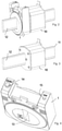
- Fig. 2 is a perspective view of a combination of a current sensor module 1 and a fuse 10.
- the fuse 10 comprises a circuit breaker which can be activated when the current strength is too high, as a result of which the electric current in the electrical conductor is interrupted.
- the current sensor module 1 includes a current sensor and electronics to measure the current and a memory to store the measured value.
- the current sensor module 1 also comprises a transmitter / receiver for transmitting the measured values to a data collecting device 5.
- the current sensor module 1 and the fuse 10 can optionally be integrated in a single housing.
- the fuse 10, shown as an example in FIG. 2 and 3 is of the blade fuse type.
- the current sensor module 1 can be pushed over a connection 12 of the fuse module 10, so that the total size of the combination of the current sensor module 1 and the fuse 10 is identical to that of a conventional fuse.
- the housing of the fuse module 10, as shown in FIG. 2 and 3 therefore, is smaller than that of a conventional fuse.
- the lengths of the protruding part of the connections 11 and 12, after placement of the current sensor module on connection 12, are substantially equal.
- Fig. 4 is a perspective view of a current sensor module 1 for use in accordance with the invention.
- the current sensor module 1 has a through hole 13 through which the terminal 12 of the fuse module 10 can be inserted.
- the current sensor module 1 comprises an energy supply (for example a supply coil) which feeds the electronic components into the sensor module or which charges a capacitor or supercap in the current sensor module for supplying the electronic components.
- an energy supply for example a supply coil
- the current sensor module 1 contains software for controlling the sensor, the transmitter and receiver and any other electronic components. Furthermore, a possibility is provided by means of a manually operated button 14 (indicated by the code “Learn”) to connect the sensor to the data collecting device 5. A correct connection with a receiver is indicated by a lighted LED 15 (indicated by the code “Link").
- the transmitter / receiver can be equipped for indoor communication, but can also be suitable for outdoor communication. Usually the transmitter / receiver 3, 4, 6 will be suitable for indoor communication and the transmitter / receiver 7 is suitable for outdoor communication.
Landscapes
- Physics & Mathematics (AREA)
- General Physics & Mathematics (AREA)
- Engineering & Computer Science (AREA)
- Power Engineering (AREA)
- Arrangements For Transmission Of Measured Signals (AREA)
- Fuses (AREA)
Description
- The present invention relates to a combination of a current sensor module for measuring an electric current through an electrical conductor and a fuse according to
claim 1, and a use according toclaim 2. - It is known in the art to measure properties of an electric current flowing through a conductor, such as the current or the voltage. For this purpose, a sensor or measuring device is placed on the conductor and the measurement is carried out.
- Such sensors and measuring devices have the property that a separate sensor or device must be used for measuring the desired properties. A user must also be at the location of the measurement.
- A drawback of the fact that one has to check the information personally is that there are many man hours with correspondingly high costs.
- One reason for carrying out such a measurement is to check the properties of an electricity grid. Furthermore, it is valuable for the network manager to know what the characteristics of the network are prior to an interruption of the electricity grid. However, only by chance a property of the electric current through a conductor before an interruption can be measured in the manner as known in the art. This is the case, for example, when an incident has occurred the cause of which is unknown. This cause cannot be determined due to a lack of measurement data.
- The invention is defined by the independent claims and now aims to provide a combination according to
claim 1 and a use according toclaim 2, wherein the sensor module is an improved sensor module - The invention also aims to include a sensor module with which an automatic measurement of desired properties can be carried out.
- Another object of the invention is to include a sensor module with which a series of measurement data obtained in the past remains available for use, management and processing.
- Another object of the invention is to provide a combination of a fuse and a sensor module according to the invention.
- In order to obtain at least one of these objectives, the invention relates to a combination of a current sensor module and a fuse according to
claim 1. Furthermore, it can transmit measurement data to a receiver which stores the data. This provides the advantage that in case of an incident, it can be checked at any time which properties or characteristics the electric current through the conductor had prior to the incident. - Surprisingly, this provides the advantage that the measurement data are available for later use, management, analysis or processing, so that the user can obtain much more information from the measurement data than originally was possible and the goal for a temporary measurement which was performed by a user on location.
- Examples of known current sensor modules are described in
WO2017/098021A1 ,US2017/059640A1 ,WO2017/078525A1 ,US2013/024139A1 andEP3093672A1 . - It has also been found that the sensor module used in the invention does not require separate energy supply. The current flowing through the conductor is sufficient to supply the sensor, as necessary. Such a synergistic effect is surprising and advantageous.
- The invention therefore relates to a combination of a current sensor module, for measuring an electric current through an electrical conductor, and a fuse, the current sensor module comprising a sensor for measuring the current strength of the electrical current flowing through the conductor, wherein the current sensor module further comprises a transmitter configured to transmit current strength data measured by the sensor to a receiver of a data collecting device wherein the current sensor module is adapted for combination with the fuse protecting the electrical conductor against overload, wherein the current sensor module is placed in a housing comprising a through hole through which one terminal extending from the housing of the fuse is inserted, and wherein the current sensor module and the fuse each have their own housing. This current sensor module provides the effect that data of the electric current through the conductor can be measured in a simple manner. As a result, at any time it is not only possible to check what the conditions were at the time of a failure of the fuse, but also to carry out a continuous analysis of the electricity network.
- The combination according to the invention is of a standardized size, so that it can easily be used. By use of the sensor module used in the invention in combination with a fuse a simple possibility is obtained to continuously collect data of the electrical current through the conductor. In particular, the total external dimension of the new sensor module and the fuse used, which collectively contains both the sensor and the transmitter and the current-interrupting part serving as a fuse, must be equal to the outer dimension of a fuse according to the state-of-the-art. Hence, in accordance with the combination of the present invention, the one of the terminals being embodied to be received in the through hole to superpose the housing of the current sensor module and the housing of the fuse, wherein the lengths of said terminals extending from the current sensor module housing and the fuse housing, after placement of the current sensor module on the one terminal, are substantially equal.
-
WO2017/098021A1 teaches a housing incorporating the fuse, a current sensing device, a microprocessor 33 and a communication module.US2017/059640A1 describes a monitoring system.WO 2017/078525 describes a system for monitoring electric current in a network comprising at least one electrical fuse.US2013/024139A1 comprises two electrical connectors for connecting the current sensor to the portion of the electrical system, such that there is a direct, physical connection of the sensor with the electrical system. - According to a further aspect, the invention relates to the use of the current sensor module in the combination according to the present invention for measuring the electric current through the electrical conductor, the current sensor module comprising the sensor for measuring the current strength of the electrical current flowing through the conductor, wherein the current sensor module further comprises the transmitter for transmitting current strength data measured by the sensor to the receiver of the data collecting device, wherein the current sensor module is adapted for combination with the fuse which is designed for protecting the electrical conductor against overload, wherein the current sensor module is placed in the housing comprising the through hole through which the one terminal extending from the housing of the fuse is inserted, wherein the fuse comprises two protruding terminals at opposite sides of the housing of the fuse, one of which terminals being embodied to be received in the through hole wherein the lengths of said terminals extending from the current sensor module housing and the fuse housing, after placement of the current sensor module on the one terminal, are substantially equal.
- Suitably, a measurement is made of the current strength through the conductor to obtain an indication of any problems occurring prior to the failure of the fuse. Therefore, the current sensor module comprises a sensor for measuring the current strength. Preferably, the sensor module further comprises a sensor for measuring the temperature.
- As mentioned above, the current sensor module further comprises a transmitter for transmitting data measured by the sensor to a receiver of a data collecting device. This allows the measurement data to be transmitted simply and instantaneously to a receiver that stores the data, for example for processing by a user. It is especially advantageous if the sensor module according to the invention also comprises a receiver in connection with carrying out software updates or the like of the electronics in the sensor module used in the invention. This can be a software update for the sensor part, but also for other components that are included in the sensor module.
- In this description, in many cases reference will be made to only one transmitter, not only referring to the transmitting part of the sensor module but also to the receiving part. The communication device in the sensor module used in the invention will usually be a transmitter / receiver. However, it is possible to design the sensor module used in the invention with only one transmitter, with which an effective embodiment of the invention is obtained. However, preference is given to a combined transmitter / receiver.
- Optionally, a sensor may be present at the current conductors for measuring the voltage in the conductors.
- It is especially preferred that the current sensor module comprises a coil for co-operation with electrical alternating current flowing through the conductor for feeding the sensor, the transmitter and optional other electronic components. A capacitor or supercap will also be able to be present as a backup power supply to provide a backup supply, which is particularly important for transmitting measurement data which have been obtained prior to a failure of a fuse, which is meant to be an interruption of the conductor and that had not yet been sent to the receiver.
- A suitable application of the sensor module used in the present invention is found in a combination with a blade fuse, the through hole being configured for receiving one blade. This is for example used in distribution boxes in city districts and the like. However, the invention is certainly not limited to a blade fuse.
- The invention can also be used, for example, in rail fuses with terminals in the rail as used in distribution boxes in Great Britain.
- According to a further aspect it relates to a combination as mentioned before comprising a further combination of the current sensor module and the data collecting device, the data collecting device comprising the receiver for receiving data transmitted by the transmitter of the current sensor module. This simply provides the possibility to collect the characteristics, ie the measured data and properties, to make them available for later processing and consideration.
- Preferably, in the combination the data collecting device comprising a receiver for receiving data transmitted by the transmitter of the current sensor module.
- The contents of the memory of the data collecting device can suitably be retrieved by a user when the data collecting device comprises a communication device for exchanging data with a user for consideration, storage, analysis or process of the data. The transmitter can be both wireless and wired. The type of wireless transmission is not limiting to the invention. Wifi, bluetooth, Zigbee, GPRS, 3G, 4G, 5G and all other wireless transmission and reception methods are in principle suitable for use in the present invention. There are also several wired types that can be used for exchange of data, for example by means of glass fiber, coax and other wired embodiments.
- A practical embodiment provides that the transmitter being part of the communication device of the data collecting device is configured to send the data to a data storage device directly accessible by the user. For example, this may occur when a user sends an order to the data collecting device. The data is then sent to a storage device from which the data can be accessed by the user. For example, the data can then be accessed by multiple users and / or uploaded for consideration and / or processing. The storage device may be a personal hard disk or a server accessible from a personal workplace (for example a cloud server) or the like.
- Finally, it is preferred that the data collecting device has an input device and output device for exchanging instructions and information with a user, preferably comprised of at least one of a keyboard and a screen or by connection for at least one of a keyboard and a screen. As a result, a user can directly access the electronic components of the data collecting device and optionally the information stored therein wirelessly. In that case, the data can, for example, be transferred directly to a data carrier of the user.
- The invention will be explained in more detail below with reference to a drawing.
-
FIG. 1 shows a schematic block diagram of an application according to the invention, -
FIG. 2 is a perspective view of a combination of a fuse and a sensor module according to the invention, -
FIG. 3 is a perspective view of a fuse for use with the sensor module according to the invention, and - FIG. 4 is a perspective view of a sensor module used in the invention.
-
Fig. 1 shows a flow diagram of the application of an embodiment of asensor module 1 and avoltage sensor module 2 used in the present invention. In addition to a circuit breaker (not shown in the diagram), the diagram comprises the voltagesensor module VSM 2, with a voltage sensor (V sensor) and the currentsensor module CSM 1 therein. The currentsensor module CSM 1 includes, among other things, an amp sensor, also referred to as current sensor or current strength sensor (C sensor), as well as a temperature sensor (T sensor), as schematically indicated incurrent sensor module 1. To control the electronics, a processing unit (CPU) is provided, as well as suitable software (SW) for that purpose. A current-to-voltage converter (C to V converter) will also be provided for feeding the electronics. A power source in the form of a supercap (not shown) may also be present for stable feeding of the electronic components. Finally, in each of thecurrent sensor module 1 and the voltage sensor module 2 a combined transmitter /receiver sensor module CSM 1 and voltage sensor module VSM 2) for transmitting measured characteristics, such as current, temperature and voltage, depending on the sensors present and, respectively, receiving, for example, software updates. - The data measured in the
voltage sensor module 2 andcurrent sensor module 1 is transmitted to areceiver 6 of adata collecting device 5. Thedata collecting device 5 also comprises a CPU and suitable software for storing the data in a memory. Thedata collecting device 5 can also comprise a temperature sensor to check its condition. In addition, thedata collecting device 5 may comprise a keyboard (KB) and a display (D), for inputting data to or extracting data from thedata collecting device 5. Thedata collecting device 5 may comprise its own power supply, for example a mains supply of 230 VAC, as in the figure shown, or its own independent battery to be able to send data and to receive and process instructions in the event of a power failure. - The
data collecting device 5 comprises one or more transmitter /receiver 7, the transmitter being suitable for continuously transmitting the received measurement data to adata storage device 8 and / or wherein the receiver is suitable for optionally first receiving instructions from, for example, an end user before sending the data received from the sensors to adata storage device 8. Alternatively, a router may be provided to connect the data collecting device to the internet, for example to provide the transmission of the measurement data to thedata storage device 8. Thedevice 8 can be an externally accessible server (for example a cloud server) or a storage disc which is directly accessible to a user. - For this purpose, the
data collecting device 5 is provided with a device 7 (for example a wireless or wired transmitter / receiver or a router) which connects thedata collecting device 5 to the internet. - The user has a direct connection to the
data storage device 8 and can view, process and examine the data from auser position 9 on a computer (PC), with keyboard (KB) and display (D), which runs suitable software (Data SW). The user in the Back Office (BO) can also have a connection to thedata collecting device 5 via the internet via a router. - The sensor module used the invention can perform a continuous measurement during, for example, every second or even every millisecond (or even better) and transmit the measured data to the
data collecting device 5. It can store the data for a predetermined period, after which the oldest data are overwritten by latest data, or can transfer the data real-time to a server for storage. For example, after detection of power failure in the fuse, by interrupting the current conductor through the fuse, the stored data can be retrieved by the user, after which thedata collecting device 5 forwards the data of a specified time-period to thedata storage device 8. From there the data can be considered, viewed, analyzed and processed through suitable back office / diagnostic software. In this way, at all times the cause of an interruption can be searched simply and successfully. The measurement data can also be analyzed for other reasons, for example to examine characteristics of power consumption or power production (in particular, but not exclusively, by solar panels). -
Fig. 2 is a perspective view of a combination of acurrent sensor module 1 and afuse 10. Thefuse 10 comprises a circuit breaker which can be activated when the current strength is too high, as a result of which the electric current in the electrical conductor is interrupted. Thecurrent sensor module 1 includes a current sensor and electronics to measure the current and a memory to store the measured value. Thecurrent sensor module 1 also comprises a transmitter / receiver for transmitting the measured values to adata collecting device 5. - In an embodiment not falling under the present invention, the
current sensor module 1 and thefuse 10 can optionally be integrated in a single housing. Thefuse 10, shown as an example inFIG. 2 and 3 , is of the blade fuse type. Thecurrent sensor module 1 can be pushed over aconnection 12 of thefuse module 10, so that the total size of the combination of thecurrent sensor module 1 and thefuse 10 is identical to that of a conventional fuse. The housing of thefuse module 10, as shown inFIG. 2 and 3 , therefore, is smaller than that of a conventional fuse. The lengths of the protruding part of theconnections connection 12, are substantially equal. - Fig. 4 is a perspective view of a
current sensor module 1 for use in accordance with the invention. Thecurrent sensor module 1 has a throughhole 13 through which theterminal 12 of thefuse module 10 can be inserted. Thecurrent sensor module 1 comprises an energy supply (for example a supply coil) which feeds the electronic components into the sensor module or which charges a capacitor or supercap in the current sensor module for supplying the electronic components. - The
current sensor module 1 contains software for controlling the sensor, the transmitter and receiver and any other electronic components. Furthermore, a possibility is provided by means of a manually operated button 14 (indicated by the code "Learn") to connect the sensor to thedata collecting device 5. A correct connection with a receiver is indicated by a lighted LED 15 (indicated by the code "Link"). - The transmitter / receiver can be equipped for indoor communication, but can also be suitable for outdoor communication. Usually the transmitter /
receiver receiver 7 is suitable for outdoor communication. - The invention is not limited to the embodiments described above and shown in the drawing. The invention is only limited by the appended claims.
Claims (10)
- A combination of a current sensor module (1), for measuring an electric current through an electrical conductor, and a fuse (10), the current sensor module (1) comprising a sensor for measuring the current strength of the electrical current flowing through the conductor,wherein the current sensor module (1) further comprises a transmitter (3) configured to transmit current strength data measured by the sensor to a receiver (6) of a data collecting device (5), wherein the current sensor module (1) is adapted for combination with the fuse (10) protecting the electrical conductor against overload, the fuse (10) comprises two protruding terminals (11, 12) at opposite sides of a housing of the fuse (10), wherein the current sensor module (1) is placed in a housing comprising a through hole (13) through which one terminal (12) extending from the housing of the fuse (10) is inserted, and wherein the current sensor module (1) and the fuse (10) each have their own housing,wherein the one (12) of the terminals (11, 12) being embodied to be received in the through hole (13) to superpose the housing of the current sensor module (1) and the housing of the fuse (10), wherein the lengths of said terminals (11, 12) extending from the current sensor module housing and the fuse housing, after placement of the current sensor module (1) on the one terminal (12), are substantially equal.
- Use of a current sensor module (1) in a combination according to claim 1 for measuring the electric current through the electrical conductor, the current sensor module (1) comprising the sensor for measuring the current strength of the electrical current flowing through the conductor,wherein the current sensor module (1) further comprises the transmitter (3) for transmitting current strength data measured by the sensor to the receiver (6) of the data collecting device (5), wherein the current sensor module (1) is adapted for combination with the fuse (10) which is designed for protecting the electrical conductor against overload, wherein the current sensor module (1) is placed in the housing comprising the through hole (13) through which the one terminal (12) extending from the housing of the fuse (10) is inserted,wherein the fuse (10) comprises two protruding terminals (11, 12), the one (12) of which terminals (11, 12) being embodied to be received in the through hole (13) wherein the lengths of said terminals (11, 12) extending from the current sensor module housing and the fuse housing, after placement of the current sensor module (1) on the one terminal (12), are substantially equal.
- Use in accordance with claim 2, wherein the current sensor module (1) comprises the sensor for measuring the current strength and a sensor for measuring the temperature.
- Use in accordance with claim 2, wherein the current sensor module (1) comprises a coil for co-operation with electrical alternating current flowing through the conductor for feeding the sensor, the transmitter (3) and optional other electronic components.
- Use in accordance with claim 2, wherein the fuse (10) is a blade fuse (10), the through hole (13) being configured for receiving the blade (12) of the blade fuse (10).
- Use in accordance with one of claims 2-5 comprising a further combination of the current sensor module (1) and the data collecting device (5), the data collecting device (5) comprising the receiver (6) for receiving data transmitted by the transmitter (3) of the current sensor module (1).
- Use in accordance with claim 6, wherein the data collecting device (5) comprises a memory for storing received data.
- Use in accordance with claim 6 or 7, wherein the data collecting device (5) comprises a communication device (7) for exchanging data with a user for consideration, storage, analysis or processing of the data.
- Use in accordance with claim 8, wherein a transmitter (7) being part of the communication device (7) of the data collecting device (5) is configured to send the data to a data storage device (8) directly accessible by the user.
- Use in accordance with one of claims 6 - 9, wherein the data collecting device (5) has an input device and output device for exchanging instructions and information with a user, preferably comprised of at least one of a keyboard and a screen or by connection for at least one of a keyboard and a screen.
Priority Applications (3)
| Application Number | Priority Date | Filing Date | Title |
|---|---|---|---|
| EP18167271.8A EP3553536B1 (en) | 2018-04-13 | 2018-04-13 | Combination of a sensor module and a fuse, and use of a sensor module in the combination |
| ES18167271T ES2912375T3 (en) | 2018-04-13 | 2018-04-13 | Combination of a sensor module and a fuse, and use of a sensor module in the combination |
| PL18167271T PL3553536T3 (en) | 2018-04-13 | 2018-04-13 | Combination of a sensor module and a fuse, and use of a sensor module in the combination |
Applications Claiming Priority (1)
| Application Number | Priority Date | Filing Date | Title |
|---|---|---|---|
| EP18167271.8A EP3553536B1 (en) | 2018-04-13 | 2018-04-13 | Combination of a sensor module and a fuse, and use of a sensor module in the combination |
Publications (2)
| Publication Number | Publication Date |
|---|---|
| EP3553536A1 EP3553536A1 (en) | 2019-10-16 |
| EP3553536B1 true EP3553536B1 (en) | 2022-03-09 |
Family
ID=62385976
Family Applications (1)
| Application Number | Title | Priority Date | Filing Date |
|---|---|---|---|
| EP18167271.8A Revoked EP3553536B1 (en) | 2018-04-13 | 2018-04-13 | Combination of a sensor module and a fuse, and use of a sensor module in the combination |
Country Status (3)
| Country | Link |
|---|---|
| EP (1) | EP3553536B1 (en) |
| ES (1) | ES2912375T3 (en) |
| PL (1) | PL3553536T3 (en) |
Families Citing this family (3)
| Publication number | Priority date | Publication date | Assignee | Title |
|---|---|---|---|---|
| ES2912375T3 (en) | 2018-04-13 | 2022-05-25 | Muco Tech B V | Combination of a sensor module and a fuse, and use of a sensor module in the combination |
| SI26034B (en) * | 2020-07-28 | 2024-09-30 | Eti Elektroelement, D.O.O. | Assembly of electric fuse with blade contacts and electric measuring device and electric fuse adapted for use in such assembly |
| KR102797999B1 (en) * | 2022-12-23 | 2025-04-21 | 에이디파워 주식회사 | Power Analysis Equipment |
Citations (14)
| Publication number | Priority date | Publication date | Assignee | Title |
|---|---|---|---|---|
| DE2312903A1 (en) | 1973-03-15 | 1974-09-19 | Driescher Spezialfab Fritz | LOW VOLTAGE HIGH PERFORMANCE FUSE |
| DE8409430U1 (en) | 1984-03-28 | 1984-09-06 | Karl Pfisterer Elektrotechnische Spezialartikel Gmbh & Co Kg, 7000 Stuttgart | Switching flap |
| DE19744765A1 (en) | 1997-10-10 | 1999-04-15 | Daimler Chrysler Ag | Fuse element circuit for automobile electrics |
| WO2005104161A1 (en) | 2004-04-20 | 2005-11-03 | Cooper Technologies Company | Wireless communication fuse state indicator system and method |
| WO2008092469A1 (en) | 2007-01-29 | 2008-08-07 | Siemens Aktiengesellschaft | Fuse, analysis device, and system with at least one fuse and at least one analysis device |
| US20130024139A1 (en) | 2011-01-21 | 2013-01-24 | Hbm Ncode Federal Llc | Current Device |
| DE202015106567U1 (en) | 2015-12-02 | 2016-01-04 | Lisa Dräxlmaier GmbH | Current measuring fuse attachment for a switch box |
| EP3093672A1 (en) * | 2015-05-09 | 2016-11-16 | LEM Intellectual Property SA | Current transducer with integrated primary conductor bar |
| US20170059640A1 (en) | 2015-08-31 | 2017-03-02 | Cooper Technologies Company | System for monitoring a fuse link, fuse tube assembly and fuse cutout including same |
| WO2017078525A1 (en) | 2015-11-06 | 2017-05-11 | Liandon B.V. | System for monitoring electric current in a network, and electrical fuse thereof |
| WO2017078884A1 (en) | 2015-07-20 | 2017-05-11 | Cooper Technologies Company | Electric fuse current sensing systems and monitoring methods |
| EP2885800B1 (en) | 2012-08-17 | 2017-05-31 | Klaus Bruchmann GmbH | Subassembly for a switch fuse arrangement having measuring device, and fuse holder for a subassembly or a switch fuse arrangement |
| WO2017098021A1 (en) | 2015-12-10 | 2017-06-15 | Monjo Systems Limited | A fuse |
| EP3553536A1 (en) | 2018-04-13 | 2019-10-16 | Muco Technologies B.V. | A sensor module for use with a fuse |
-
2018
- 2018-04-13 ES ES18167271T patent/ES2912375T3/en active Active
- 2018-04-13 EP EP18167271.8A patent/EP3553536B1/en not_active Revoked
- 2018-04-13 PL PL18167271T patent/PL3553536T3/en unknown
Patent Citations (14)
| Publication number | Priority date | Publication date | Assignee | Title |
|---|---|---|---|---|
| DE2312903A1 (en) | 1973-03-15 | 1974-09-19 | Driescher Spezialfab Fritz | LOW VOLTAGE HIGH PERFORMANCE FUSE |
| DE8409430U1 (en) | 1984-03-28 | 1984-09-06 | Karl Pfisterer Elektrotechnische Spezialartikel Gmbh & Co Kg, 7000 Stuttgart | Switching flap |
| DE19744765A1 (en) | 1997-10-10 | 1999-04-15 | Daimler Chrysler Ag | Fuse element circuit for automobile electrics |
| WO2005104161A1 (en) | 2004-04-20 | 2005-11-03 | Cooper Technologies Company | Wireless communication fuse state indicator system and method |
| WO2008092469A1 (en) | 2007-01-29 | 2008-08-07 | Siemens Aktiengesellschaft | Fuse, analysis device, and system with at least one fuse and at least one analysis device |
| US20130024139A1 (en) | 2011-01-21 | 2013-01-24 | Hbm Ncode Federal Llc | Current Device |
| EP2885800B1 (en) | 2012-08-17 | 2017-05-31 | Klaus Bruchmann GmbH | Subassembly for a switch fuse arrangement having measuring device, and fuse holder for a subassembly or a switch fuse arrangement |
| EP3093672A1 (en) * | 2015-05-09 | 2016-11-16 | LEM Intellectual Property SA | Current transducer with integrated primary conductor bar |
| WO2017078884A1 (en) | 2015-07-20 | 2017-05-11 | Cooper Technologies Company | Electric fuse current sensing systems and monitoring methods |
| US20170059640A1 (en) | 2015-08-31 | 2017-03-02 | Cooper Technologies Company | System for monitoring a fuse link, fuse tube assembly and fuse cutout including same |
| WO2017078525A1 (en) | 2015-11-06 | 2017-05-11 | Liandon B.V. | System for monitoring electric current in a network, and electrical fuse thereof |
| DE202015106567U1 (en) | 2015-12-02 | 2016-01-04 | Lisa Dräxlmaier GmbH | Current measuring fuse attachment for a switch box |
| WO2017098021A1 (en) | 2015-12-10 | 2017-06-15 | Monjo Systems Limited | A fuse |
| EP3553536A1 (en) | 2018-04-13 | 2019-10-16 | Muco Technologies B.V. | A sensor module for use with a fuse |
Non-Patent Citations (1)
| Title |
|---|
| JEAN MÜLLER: "Sicherungen für die nieder - und hochspannung", PRODUKTKATALOG, 2010, pages 1 - 27, XP093010943 |
Also Published As
| Publication number | Publication date |
|---|---|
| EP3553536A1 (en) | 2019-10-16 |
| PL3553536T3 (en) | 2022-06-27 |
| ES2912375T3 (en) | 2022-05-25 |
Similar Documents
| Publication | Publication Date | Title |
|---|---|---|
| EP2480862B1 (en) | Telemetry system | |
| NL2015736B1 (en) | System for monitoring electric current in a network, and electrical fuse thereof. | |
| US10080069B2 (en) | Collection of telemetry data through a meter reading system | |
| US10564193B2 (en) | Energy monitoring and analysis system | |
| US20050151659A1 (en) | Transmission/distribution line fault indicator with remote polling and current sensing and reporting capability | |
| US10114037B2 (en) | Systems and methods for current and voltage monitoring | |
| US8965717B2 (en) | Carbon emission tracker and tracking system | |
| EP3553536B1 (en) | Combination of a sensor module and a fuse, and use of a sensor module in the combination | |
| WO2012007831A2 (en) | Circuit breaker with integral meter and wireless communications | |
| EP3318884A1 (en) | Power monitoring probe for monitoring power distribution in an electrical system | |
| HK1255033A1 (en) | Power monitoring probe for monitoring power distribution in an electrical system | |
| GB2450426A (en) | Circuit breaker electrical power consumption monitoring | |
| EP4257989B1 (en) | Modular sensor platform apparatus | |
| CN209786878U (en) | Intelligent power distribution room online monitoring system | |
| CN102842960A (en) | Local monitoring apparatus, monitoring system and method of digital protective relay | |
| CN212258984U (en) | Gateway device of Internet of things | |
| CN203689650U (en) | Daily electricity consumption model collection device and daily electricity consumption model acquisition system | |
| KR100781333B1 (en) | Integrated monitoring system for ground resistance of pole ground wire | |
| JP6440129B2 (en) | Status notification device | |
| CN205593557U (en) | A detection device and detecting system for generating line | |
| CN208570841U (en) | A kind of battery monitor equipment | |
| JP5934943B2 (en) | Power measuring device | |
| WO2020235745A1 (en) | Energy management system | |
| CN107167173A (en) | Detection means and detecting system for bus |
Legal Events
| Date | Code | Title | Description |
|---|---|---|---|
| PUAI | Public reference made under article 153(3) epc to a published international application that has entered the european phase |
Free format text: ORIGINAL CODE: 0009012 |
|
| STAA | Information on the status of an ep patent application or granted ep patent |
Free format text: STATUS: REQUEST FOR EXAMINATION WAS MADE |
|
| 17P | Request for examination filed |
Effective date: 20190227 |
|
| AK | Designated contracting states |
Kind code of ref document: A1 Designated state(s): AL AT BE BG CH CY CZ DE DK EE ES FI FR GB GR HR HU IE IS IT LI LT LU LV MC MK MT NL NO PL PT RO RS SE SI SK SM TR |
|
| AX | Request for extension of the european patent |
Extension state: BA ME |
|
| STAA | Information on the status of an ep patent application or granted ep patent |
Free format text: STATUS: EXAMINATION IS IN PROGRESS |
|
| 17Q | First examination report despatched |
Effective date: 20191024 |
|
| GRAP | Despatch of communication of intention to grant a patent |
Free format text: ORIGINAL CODE: EPIDOSNIGR1 |
|
| STAA | Information on the status of an ep patent application or granted ep patent |
Free format text: STATUS: GRANT OF PATENT IS INTENDED |
|
| INTG | Intention to grant announced |
Effective date: 20211208 |
|
| GRAS | Grant fee paid |
Free format text: ORIGINAL CODE: EPIDOSNIGR3 |
|
| GRAA | (expected) grant |
Free format text: ORIGINAL CODE: 0009210 |
|
| STAA | Information on the status of an ep patent application or granted ep patent |
Free format text: STATUS: THE PATENT HAS BEEN GRANTED |
|
| AK | Designated contracting states |
Kind code of ref document: B1 Designated state(s): AL AT BE BG CH CY CZ DE DK EE ES FI FR GB GR HR HU IE IS IT LI LT LU LV MC MK MT NL NO PL PT RO RS SE SI SK SM TR |
|
| REG | Reference to a national code |
Ref country code: CH Ref legal event code: EP Ref country code: AT Ref legal event code: REF Ref document number: 1474600 Country of ref document: AT Kind code of ref document: T Effective date: 20220315 |
|
| REG | Reference to a national code |
Ref country code: DE Ref legal event code: R096 Ref document number: 602018031844 Country of ref document: DE |
|
| REG | Reference to a national code |
Ref country code: IE Ref legal event code: FG4D |
|
| REG | Reference to a national code |
Ref country code: NL Ref legal event code: FP |
|
| REG | Reference to a national code |
Ref country code: ES Ref legal event code: FG2A Ref document number: 2912375 Country of ref document: ES Kind code of ref document: T3 Effective date: 20220525 |
|
| REG | Reference to a national code |
Ref country code: LT Ref legal event code: MG9D |
|
| PG25 | Lapsed in a contracting state [announced via postgrant information from national office to epo] |
Ref country code: SE Free format text: LAPSE BECAUSE OF FAILURE TO SUBMIT A TRANSLATION OF THE DESCRIPTION OR TO PAY THE FEE WITHIN THE PRESCRIBED TIME-LIMIT Effective date: 20220309 Ref country code: RS Free format text: LAPSE BECAUSE OF FAILURE TO SUBMIT A TRANSLATION OF THE DESCRIPTION OR TO PAY THE FEE WITHIN THE PRESCRIBED TIME-LIMIT Effective date: 20220309 Ref country code: NO Free format text: LAPSE BECAUSE OF FAILURE TO SUBMIT A TRANSLATION OF THE DESCRIPTION OR TO PAY THE FEE WITHIN THE PRESCRIBED TIME-LIMIT Effective date: 20220609 Ref country code: LT Free format text: LAPSE BECAUSE OF FAILURE TO SUBMIT A TRANSLATION OF THE DESCRIPTION OR TO PAY THE FEE WITHIN THE PRESCRIBED TIME-LIMIT Effective date: 20220309 Ref country code: HR Free format text: LAPSE BECAUSE OF FAILURE TO SUBMIT A TRANSLATION OF THE DESCRIPTION OR TO PAY THE FEE WITHIN THE PRESCRIBED TIME-LIMIT Effective date: 20220309 Ref country code: BG Free format text: LAPSE BECAUSE OF FAILURE TO SUBMIT A TRANSLATION OF THE DESCRIPTION OR TO PAY THE FEE WITHIN THE PRESCRIBED TIME-LIMIT Effective date: 20220609 |
|
| REG | Reference to a national code |
Ref country code: AT Ref legal event code: MK05 Ref document number: 1474600 Country of ref document: AT Kind code of ref document: T Effective date: 20220309 |
|
| PG25 | Lapsed in a contracting state [announced via postgrant information from national office to epo] |
Ref country code: LV Free format text: LAPSE BECAUSE OF FAILURE TO SUBMIT A TRANSLATION OF THE DESCRIPTION OR TO PAY THE FEE WITHIN THE PRESCRIBED TIME-LIMIT Effective date: 20220309 Ref country code: GR Free format text: LAPSE BECAUSE OF FAILURE TO SUBMIT A TRANSLATION OF THE DESCRIPTION OR TO PAY THE FEE WITHIN THE PRESCRIBED TIME-LIMIT Effective date: 20220610 Ref country code: FI Free format text: LAPSE BECAUSE OF FAILURE TO SUBMIT A TRANSLATION OF THE DESCRIPTION OR TO PAY THE FEE WITHIN THE PRESCRIBED TIME-LIMIT Effective date: 20220309 |
|
| PG25 | Lapsed in a contracting state [announced via postgrant information from national office to epo] |
Ref country code: SM Free format text: LAPSE BECAUSE OF FAILURE TO SUBMIT A TRANSLATION OF THE DESCRIPTION OR TO PAY THE FEE WITHIN THE PRESCRIBED TIME-LIMIT Effective date: 20220309 Ref country code: SK Free format text: LAPSE BECAUSE OF FAILURE TO SUBMIT A TRANSLATION OF THE DESCRIPTION OR TO PAY THE FEE WITHIN THE PRESCRIBED TIME-LIMIT Effective date: 20220309 Ref country code: RO Free format text: LAPSE BECAUSE OF FAILURE TO SUBMIT A TRANSLATION OF THE DESCRIPTION OR TO PAY THE FEE WITHIN THE PRESCRIBED TIME-LIMIT Effective date: 20220309 Ref country code: PT Free format text: LAPSE BECAUSE OF FAILURE TO SUBMIT A TRANSLATION OF THE DESCRIPTION OR TO PAY THE FEE WITHIN THE PRESCRIBED TIME-LIMIT Effective date: 20220711 Ref country code: EE Free format text: LAPSE BECAUSE OF FAILURE TO SUBMIT A TRANSLATION OF THE DESCRIPTION OR TO PAY THE FEE WITHIN THE PRESCRIBED TIME-LIMIT Effective date: 20220309 Ref country code: CZ Free format text: LAPSE BECAUSE OF FAILURE TO SUBMIT A TRANSLATION OF THE DESCRIPTION OR TO PAY THE FEE WITHIN THE PRESCRIBED TIME-LIMIT Effective date: 20220309 Ref country code: AT Free format text: LAPSE BECAUSE OF FAILURE TO SUBMIT A TRANSLATION OF THE DESCRIPTION OR TO PAY THE FEE WITHIN THE PRESCRIBED TIME-LIMIT Effective date: 20220309 |
|
| PG25 | Lapsed in a contracting state [announced via postgrant information from national office to epo] |
Ref country code: IS Free format text: LAPSE BECAUSE OF FAILURE TO SUBMIT A TRANSLATION OF THE DESCRIPTION OR TO PAY THE FEE WITHIN THE PRESCRIBED TIME-LIMIT Effective date: 20220709 Ref country code: AL Free format text: LAPSE BECAUSE OF FAILURE TO SUBMIT A TRANSLATION OF THE DESCRIPTION OR TO PAY THE FEE WITHIN THE PRESCRIBED TIME-LIMIT Effective date: 20220309 |
|
| REG | Reference to a national code |
Ref country code: CH Ref legal event code: PL |
|
| REG | Reference to a national code |
Ref country code: DE Ref legal event code: R026 Ref document number: 602018031844 Country of ref document: DE |
|
| PLBI | Opposition filed |
Free format text: ORIGINAL CODE: 0009260 |
|
| PLAB | Opposition data, opponent's data or that of the opponent's representative modified |
Free format text: ORIGINAL CODE: 0009299OPPO |
|
| PLAX | Notice of opposition and request to file observation + time limit sent |
Free format text: ORIGINAL CODE: EPIDOSNOBS2 |
|
| 26 | Opposition filed |
Opponent name: SIEMENS AKTIENGESELLSCHAFT Effective date: 20221208 |
|
| R26 | Opposition filed (corrected) |
Opponent name: SIEMENS AKTIENGESELLSCHAFT Effective date: 20221208 |
|
| PG25 | Lapsed in a contracting state [announced via postgrant information from national office to epo] |
Ref country code: MC Free format text: LAPSE BECAUSE OF FAILURE TO SUBMIT A TRANSLATION OF THE DESCRIPTION OR TO PAY THE FEE WITHIN THE PRESCRIBED TIME-LIMIT Effective date: 20220309 Ref country code: LU Free format text: LAPSE BECAUSE OF NON-PAYMENT OF DUE FEES Effective date: 20220413 Ref country code: LI Free format text: LAPSE BECAUSE OF NON-PAYMENT OF DUE FEES Effective date: 20220430 Ref country code: DK Free format text: LAPSE BECAUSE OF FAILURE TO SUBMIT A TRANSLATION OF THE DESCRIPTION OR TO PAY THE FEE WITHIN THE PRESCRIBED TIME-LIMIT Effective date: 20220309 Ref country code: CH Free format text: LAPSE BECAUSE OF NON-PAYMENT OF DUE FEES Effective date: 20220430 |
|
| PLAB | Opposition data, opponent's data or that of the opponent's representative modified |
Free format text: ORIGINAL CODE: 0009299OPPO |
|
| PG25 | Lapsed in a contracting state [announced via postgrant information from national office to epo] |
Ref country code: SI Free format text: LAPSE BECAUSE OF FAILURE TO SUBMIT A TRANSLATION OF THE DESCRIPTION OR TO PAY THE FEE WITHIN THE PRESCRIBED TIME-LIMIT Effective date: 20220309 |
|
| GBPC | Gb: european patent ceased through non-payment of renewal fee |
Effective date: 20220609 |
|
| R26 | Opposition filed (corrected) |
Opponent name: SIEMENS AKTIENGESELLSCHAFT Effective date: 20221208 |
|
| PLBB | Reply of patent proprietor to notice(s) of opposition received |
Free format text: ORIGINAL CODE: EPIDOSNOBS3 |
|
| PG25 | Lapsed in a contracting state [announced via postgrant information from national office to epo] |
Ref country code: IE Free format text: LAPSE BECAUSE OF NON-PAYMENT OF DUE FEES Effective date: 20220413 |
|
| PG25 | Lapsed in a contracting state [announced via postgrant information from national office to epo] |
Ref country code: GB Free format text: LAPSE BECAUSE OF NON-PAYMENT OF DUE FEES Effective date: 20220609 |
|
| PGFP | Annual fee paid to national office [announced via postgrant information from national office to epo] |
Ref country code: NL Payment date: 20230427 Year of fee payment: 6 |
|
| PGFP | Annual fee paid to national office [announced via postgrant information from national office to epo] |
Ref country code: IT Payment date: 20230427 Year of fee payment: 6 Ref country code: FR Payment date: 20230424 Year of fee payment: 6 Ref country code: ES Payment date: 20230503 Year of fee payment: 6 Ref country code: DE Payment date: 20230428 Year of fee payment: 6 |
|
| PGFP | Annual fee paid to national office [announced via postgrant information from national office to epo] |
Ref country code: TR Payment date: 20230424 Year of fee payment: 6 Ref country code: PL Payment date: 20230421 Year of fee payment: 6 |
|
| RDAF | Communication despatched that patent is revoked |
Free format text: ORIGINAL CODE: EPIDOSNREV1 |
|
| PGFP | Annual fee paid to national office [announced via postgrant information from national office to epo] |
Ref country code: BE Payment date: 20230424 Year of fee payment: 6 |
|
| REG | Reference to a national code |
Ref country code: DE Ref legal event code: R103 Ref document number: 602018031844 Country of ref document: DE Ref country code: DE Ref legal event code: R064 Ref document number: 602018031844 Country of ref document: DE |
|
| RDAG | Patent revoked |
Free format text: ORIGINAL CODE: 0009271 |
|
| STAA | Information on the status of an ep patent application or granted ep patent |
Free format text: STATUS: PATENT REVOKED |
|
| REG | Reference to a national code |
Ref country code: CH Ref legal event code: PL |
|
| 27W | Patent revoked |
Effective date: 20231006 |
|
| PG25 | Lapsed in a contracting state [announced via postgrant information from national office to epo] |
Ref country code: MK Free format text: LAPSE BECAUSE OF FAILURE TO SUBMIT A TRANSLATION OF THE DESCRIPTION OR TO PAY THE FEE WITHIN THE PRESCRIBED TIME-LIMIT Effective date: 20220309 Ref country code: CY Free format text: LAPSE BECAUSE OF FAILURE TO SUBMIT A TRANSLATION OF THE DESCRIPTION OR TO PAY THE FEE WITHIN THE PRESCRIBED TIME-LIMIT Effective date: 20220309 |
|
| PG25 | Lapsed in a contracting state [announced via postgrant information from national office to epo] |
Ref country code: HU Free format text: LAPSE BECAUSE OF FAILURE TO SUBMIT A TRANSLATION OF THE DESCRIPTION OR TO PAY THE FEE WITHIN THE PRESCRIBED TIME-LIMIT; INVALID AB INITIO Effective date: 20180413 |
|
| PG25 | Lapsed in a contracting state [announced via postgrant information from national office to epo] |
Ref country code: MT Free format text: LAPSE BECAUSE OF FAILURE TO SUBMIT A TRANSLATION OF THE DESCRIPTION OR TO PAY THE FEE WITHIN THE PRESCRIBED TIME-LIMIT Effective date: 20220309 |