EP3553470A1 - Automatische mobile vorrichtung, automatisches arbeitssystem und steuerungsverfahren dafür - Google Patents
Automatische mobile vorrichtung, automatisches arbeitssystem und steuerungsverfahren dafür Download PDFInfo
- Publication number
- EP3553470A1 EP3553470A1 EP17700031.2A EP17700031A EP3553470A1 EP 3553470 A1 EP3553470 A1 EP 3553470A1 EP 17700031 A EP17700031 A EP 17700031A EP 3553470 A1 EP3553470 A1 EP 3553470A1
- Authority
- EP
- European Patent Office
- Prior art keywords
- signal
- gain
- gain signal
- working system
- threshold value
- Prior art date
- Legal status (The legal status is an assumption and is not a legal conclusion. Google has not performed a legal analysis and makes no representation as to the accuracy of the status listed.)
- Granted
Links
Images


Classifications
-
- G—PHYSICS
- G05—CONTROLLING; REGULATING
- G05D—SYSTEMS FOR CONTROLLING OR REGULATING NON-ELECTRIC VARIABLES
- G05D1/00—Control of position, course, altitude or attitude of land, water, air or space vehicles, e.g. using automatic pilots
- G05D1/02—Control of position or course in two dimensions
- G05D1/021—Control of position or course in two dimensions specially adapted to land vehicles
- G05D1/0259—Control of position or course in two dimensions specially adapted to land vehicles using magnetic or electromagnetic means
- G05D1/0265—Control of position or course in two dimensions specially adapted to land vehicles using magnetic or electromagnetic means using buried wires
-
- G—PHYSICS
- G05—CONTROLLING; REGULATING
- G05D—SYSTEMS FOR CONTROLLING OR REGULATING NON-ELECTRIC VARIABLES
- G05D1/00—Control of position, course, altitude or attitude of land, water, air or space vehicles, e.g. using automatic pilots
- G05D1/02—Control of position or course in two dimensions
- G05D1/021—Control of position or course in two dimensions specially adapted to land vehicles
- G05D1/0259—Control of position or course in two dimensions specially adapted to land vehicles using magnetic or electromagnetic means
-
- G—PHYSICS
- G05—CONTROLLING; REGULATING
- G05D—SYSTEMS FOR CONTROLLING OR REGULATING NON-ELECTRIC VARIABLES
- G05D1/00—Control of position, course, altitude or attitude of land, water, air or space vehicles, e.g. using automatic pilots
- G05D1/02—Control of position or course in two dimensions
- G05D1/021—Control of position or course in two dimensions specially adapted to land vehicles
- G05D1/0212—Control of position or course in two dimensions specially adapted to land vehicles with means for defining a desired trajectory
- G05D1/0225—Control of position or course in two dimensions specially adapted to land vehicles with means for defining a desired trajectory involving docking at a fixed facility, e.g. base station or loading bay
-
- G—PHYSICS
- G05—CONTROLLING; REGULATING
- G05D—SYSTEMS FOR CONTROLLING OR REGULATING NON-ELECTRIC VARIABLES
- G05D1/00—Control of position, course, altitude or attitude of land, water, air or space vehicles, e.g. using automatic pilots
- G05D1/02—Control of position or course in two dimensions
- G05D1/021—Control of position or course in two dimensions specially adapted to land vehicles
- G05D1/0268—Control of position or course in two dimensions specially adapted to land vehicles using internal positioning means
Definitions
- the present invention relates to an automatic working system, in particular to a system controlling an automatic moving device to work in a working region.
- the present invention relates to a control method, in particular to a control method controlling an automatic moving device to work in a working region.
- the present invention relates to an automatic moving device, in particular to an automatic moving device working and moving in a working region automatically.
- an intelligent automatic moving device is known by people very well, since the automatic moving device can execute preset related tasks by an automatically preset program without artificial operation and intervention, and is thus industrial application and application on household products is very wide.
- the industrial application comprises for example robots executing various functions
- the application on the household products comprises for example a mower, a dust collector and the like, and these intelligent automatic moving devices greatly save people's time and bring great convenience to industrial production and household life.
- Such automatic moving device usually moves in a preset working region automatically without leaving the preset working region.
- An outer boundary of the preset working region is determined by adopting a boundary wire generally.
- the boundary wire is a common wire generally.
- a generated electric field or magnetic field can be detected by a proper sensor in the automatic moving device, a detected signal is then transmitted to a processor built in the automatic moving device, and a processor compares the obtained signal with a preset judging criterion in a memory, and thus obtains whether the automatic moving device is in the working region or not.
- the automatic working system comprises a signal generating device 80', a boundary wire 50' electrically connected to the signal generating device, and an automatic moving device 10'.
- the boundary wire 50' defined a working region 30' surrounded by the boundary wire 50' and a non-working region 70' located outside a circle of the boundary wire 50'.
- the signal generating device 80' generates a periodic current signal SS as shown in Fig. 2 .
- the current signal SS will generate an electromagnetic field 90' changed by taking the boundary wire 50' as a center when flows through the boundary wire 50'. At any moment, the polarity of the electromagnetic field 90' in the working region 30' is opposite to that in the non-working region 70'.
- the automatic moving device 10' further comprises a signal detecting device 20' and a processor (not shown).
- the signal detecting device 20' is usually a sensing coil, which generates a detection signal by sensing the changed electromagnetic field 90', such as an AC voltage or AC current.
- the processor receives and processes the detection signal, and compares the detection signal with a threshold value preset in the processor, when an amplitude of the voltage or current exceeds the threshold value, the processor indicates the automatic moving device 10' to get away from the boundary wire 50' of the working region.
- a threshold value preset in the processor when an amplitude of the voltage or current exceeds the threshold value, the processor indicates the automatic moving device 10' to get away from the boundary wire 50' of the working region.
- a phase of the detection signal sensed by a signal detecting device 110' is also reversed.
- the processor judges that the automatic working device is in the non-working region 70' by recognizing that the phase direction of the detection signal is different from a preset phase direction.
- the automatic working device 10' is necessarily provided with a motor driving the automatic working device to walk and/or a motor driving mowing or dust collecting and other working parts of the automatic working device to work, and the operation of the motor will generate an electromagnetic field.
- Such electromagnetic field will be sensed by the signal detecting device 110' to generate a voltage or current signal. Therefore, the detection signal received by the processor actually contains an interference signal brought by the motor.
- the processor often misjudges the inside and outside and sends a control command not according with an actual condition.
- the detection signals obtained by sensing of the automatic working devices in respective working regions necessarily contain the interference brought by the adjacent electromagnetic fields. Therefore, the detection signals received by the respective processors actually contain the interference signals brought by the electromagnetic fields in the adjacent working regions.
- the processor often misjudges the inside and outside and sends a control command not according with an actual condition.
- the automatic working device 10' necessarily works in a free space, while various electromagnetic waves sent by various radio devices or other types of devices exist in the free space.
- a certain electromagnetic signal is possibly sensed by the signal detecting device 110' at a certain moment. Therefore, the detection signal SJ' received by the processor actually contains the interference signal brought by electromagnetic waves in the free space.
- the processor often misjudges the inside and outside and sends a control command not according with an actual condition.
- the invention solves a technical problem about providing an automatic working system, a control method and an automatic moving device, which can automatically adjust the size of a detection signal and eliminating or reducing an interference signal.
- a technical solution of the present invention is: a control method of an automatic working system, said automatic working system comprises a signal generating device for generating a current signal, said current signal generating an electromagnetic field when flowing through a boundary wire; and an automatic moving device, said automatic moving device having at least one detecting device for detecting said electromagnetic field; the control method comprising the following steps:
- said feature point comprises an extreme point of said gain signal, and said extreme point comprises a peak value and/or a valley value.
- said upper threshold value and said lower threshold value are fixed values.
- said automatic moving device further comprises a processor for processing the at least one gain signal, and said preset condition is disposed in said processor.
- the step of amplifying said at least one detection signal to form at least one gain signal can be performed by a programmable gain amplifier.
- the step of amplifying said at least one detection signal to form at least one gain signal can be performed by a fixed gain amplifier.
- a level of the amplification factor of said programmable gain amplifier are one of 2-6 levels.
- a level of the amplification factor of said programmable gain amplifier is are 5 levels.
- said amplification factor of said programmable gain amplifier is 1/2 to 16 times of said gain signal.
- said gain signal according with said preset condition is output, further comprising an analog to digital conversion step for converting said gain signal into a digital signal.
- said denoising step further comprising a judging step, for judging that said detecting device is in or outside said boundary wire based on a denoised digital signal and forming at least one moving signal
- a driving step for driving said automatic moving device to move according to said at least one moving signal
- said at least one detecting device comprises a first detecting device and a second detecting device; said first detecting device and said second detecting device detect said electromagnetic field to generate a first detection signal and a second detection signal respectively.
- amplifying said first detection signal and said second detection signal to form a first gain signal and a second gain signal compare said first detection signal and said second detection signal with said preset condition respectively, and adjust amplification factors of said first gain signal and said second gain signal are respectively according to a comparing result.
- the present invention also provides a technical solution, an automatic working system, comprising:
- said feature point comprises an extreme point of said gain signal, and said extreme point comprises a peak value and/or a valley value.
- said adjusting module adjusts the amplification factor of said gain signal.
- said upper threshold value and said lower threshold value are fixed values.
- said automatic moving device further comprises a processor for processing said at least one gain signal, and said preset condition is disposed in said processor.
- said adjusting module comprises a programmable gain amplifier.
- said adjusting module comprises a fixed gain amplifier.
- a level of the amplification factor of said programmable gain amplifier are one of 2-6 levels.
- a level of the amplification factor of said programmable gain amplifier are 5 levels.
- said amplification factor of said programmable gain amplifier is 1/2 to 16 times of said gain signal.
- an analog to digital converter is electrically connected to said adjusting module, configured to convert said gain signal into a digital signal.
- said analog to digital converter is a differential analog to digital converter.
- a denoising module is electrically connected to said analog to digital converter , configured to remove an interference signal of said digital signal.
- a judging module is electrically connected to said denoising module, configured to judge that said detecting device is in or outside said boundary wire based on a denoised digital signal and then forms at least one moving signal.
- a controller is electrically connected to said judging module, configured to receive said moving signal to drive said automatic moving device to move.
- said comparing module, said adjusting module, said analog to digital converter, said denoising module and said judging module are integrated in said processor.
- said at least one detecting device comprises a first detecting device and a second detecting device; said first detecting device and said second detecting device detect said electromagnetic field to generate a first detection signal and a second detection signal respectively.
- said adjusting module amplifies said first detection signal and said second detection signal to form a first gain signal and a second gain signal respectively
- said comparing module compares said first gain signal and said second gain signal with said preset condition respectively
- said adjusting module adjusts an amplification factor of said first gain signal and said second gain signal respectively according to a comparing result.
- an automatic moving device comprising:
- the feature point comprises an extreme point of said gain signal, and said extreme point comprises a peak value and/or a valley value.
- said adjusting module adjusts said amplification factor of said gain signal.
- said upper threshold value and said lower threshold value are fixed values.
- said automatic moving device further comprises a processor for processing said at least one gain signal, and said preset condition is disposed in said processor.
- a level of said amplification factor of said programmable gain amplifier are one of 2-6 levels, and said amplification factor of said programmable gain amplifier is 1/2 to 16 times of said gain signal.
- said adjusting module comprises a programmable gain amplifier.
- said adjusting module comprises a fixed gain amplifier.
- an analog to digital converter electrically connected to said adjusting module, configured to convert said gain signal into a digital signal.
- said analog to digital converter is a differential analog to digital converter.
- the present invention also provides a technical solution, a control method of an automatic working system, said automatic working system comprises: a signal generating device for generating a current signal, said current signal generating an electromagnetic field when flowing through a boundary wire; and an automatic moving device ,said automatic moving device having at least one detecting device for detecting the electromagnetic field; comprising the following steps:
- said extreme point comprises a peak value and/or a valley value of said gain signal.
- the amplification factor of said gain signal is adjusted.
- said upper threshold value and said lower threshold value are fixed values.
- said automatic moving device further comprises a processor for processing the at least one gain signal, and said preset condition is disposed in said processor.
- the step of amplifying said at least one detection signal to form at least one gain signal can be performed by a programmable gain amplifier.
- the step of amplifying said at least one detection signal to form at least one gain signal can be performed by a fixed gain amplifier.
- a level of the amplification factor of said programmable gain amplifier are one of 2-6 levels.
- a level of the amplification factor of said programmable gain amplifier are 5 levels.
- the amplification factor of said programmable gain amplifier is 1/2 to 16 times of said gain signal.
- said gain signal according with said preset condition is output, further comprising an analog to digital conversion step for converting said gain signal into a digital signal.
- said denoising step further comprising a judging step, for judging that said detecting device is in or outside the boundary wire based on a denoised digital signal and forming at least one moving signal
- a driving step for driving said automatic moving device to move according to said at least one moving signal
- said at least one detecting device comprises a first detecting device and a second detecting device; said first detecting device and said second detecting device detect said electromagnetic field to generate a first detection signal and a second detection signal respectively.
- said first detection signal and said second detection signal are amplified to form a first gain signal and a second gain signal, which are compared with said preset condition respectively, and amplification factors of said first gain signal and said second gain signal are respectively adjusted according to a comparing result.
- the present invention also provides a technical solution, an automatic working system, comprising:
- said extreme point comprises a peak value and/or a valley value of said gain signal.
- said adjusting module adjusts the amplification factor of said gain signal.
- said upper threshold value and said lower threshold value are fixed values.
- said automatic moving device further comprises a processor for processing said at least one gain signal, and said preset condition is disposed in said processor.
- said adjusting module comprises a programmable gain amplifier.
- said adjusting module comprises a fixed gain amplifier.
- a level of the amplification factor of said programmable gain amplifier are one of 2-6 levels.
- a level of the amplification factor of said programmable gain amplifier are 5 levels.
- the amplification factor of said programmable gain amplifier is 1/2 to 16 times of said gain signal.
- an analog to digital converter is electrically connected to said adjusting module, configured to convert said gain signal into a digital signal.
- said analog to digital converter is a differential analog to digital converter.
- a denoising module is electrically connected to said analog to digital converter, configured to remove an interference signal of said digital signal.
- ajudging module is electrically connected to said denoising module, configured to judge that said detecting device is in or outside said boundary wire based on a denoised digital signal and then forms at least one moving signal.
- a controller is electrically connected to said judging module configured to receive said moving signal to drive said automatic moving device to move.
- said comparing module, said adjusting module, said analog to digital converter, said denoising module and said judging module are integrated in said processor.
- At least one detecting device comprises a first detecting device and a second detecting device; said first detecting device and said second detecting device detect said electromagnetic field to generate a first detection signal and a second detection signal respectively.
- said adjusting module amplifies said first detection signal and said second detection signal to form a first gain signal and a second gain signal respectively, said comparing module compares said first gain signal and said second gain signal with said preset condition respectively, and said adjusting module adjusts an amplification factor of said first gain signal and said second gain signal respectively according to a comparing result.
- an automatic moving device comprising:
- said extreme point comprises a peak value and/or a valley value of said gain signal.
- said adjusting modules adjusts the amplification factor of said gain signal.
- said upper threshold value and said lower threshold value are fixed values.
- said automatic moving device further comprises a processor for processing said at least one gain signal, and said preset condition is disposed in said processor.
- the adjusting modules comprises a programmable gain amplifier.
- said adjusting modules comprises a fixed gain amplifier.
- a level of the amplification factor of said programmable gain amplifier are one of 2-6 levels.
- a level of the amplification factor of said programmable gain amplifier are 5 levels.
- the amplification factor of said programmable gain amplifier is 1/2 to 16 times of said gain signal.
- an analog to digital converter is electrically connected to said adjusting module, configured to convert said gain signal into a digital signal.
- said analog to digital converter is a differential analog to digital converter.
- a denoising module is electrically connected to said adjusting module, configured to remove an interference signal of said digital signal.
- a judging module is electrically connected to said denoising module, configured to judge that said detecting device is in or outside said boundary wire based on a denoised digital signal and then forms at least one moving signal.
- a controller is electrically connected to said judging module, configured to receive the moving signal to drive said automatic moving device to move.
- said comparing module, said adjusting module, said analog to digital converter, said denoising module and said judging module are integrated in said processor.
- said at least one detecting device comprises a first detecting device and a second detecting device; said first detecting device and said second detecting device detect the electromagnetic field to generate a first detection signal and a second detection signal respectively.
- said adjusting module amplifies said first detection signal and said second detection signal to form a first gain signal and a second gain signal respectively
- said comparing module compares said first gain signal and said second gain signal with said preset condition respectively
- said adjusting module adjusts an amplification factor of said first gain signal and said second gain signal respectively according to a comparing result.
- said first detecting device and said second detecting device are symmetric about a middle axis of said automatic moving device.
- the present invention also provides a technical solution, an automatic working system, comprising:
- a controller is electrically connected to said processor, configured to receive a signal output from said processor to drive said automatic moving device to move.
- a level of the amplification factor of said programmable gain amplifier are one of 2-6 levels.
- a level of the amplification factor of said programmable gain amplifier are 5 levels.
- a level of the amplification factor of said programmable gain amplifier is 1/2 to 16 times of said gain signal.
- preset condition comprises that an extreme point of said gain signal is lower than an upper threshold value and higher than a lower threshold value.
- said extreme point comprises a peak value and/or valley value of said gain signal.
- said programmable gain amplifier adjusts the amplification factor of said gain signal.
- said upper threshold value and said lower threshold value are fixed values.
- said preset condition is disposed in said processor.
- an analog to digital converter is electrically connected to said programmable gain amplifier,configured to convert said gain signal into a digital signal.
- said analog to digital converter is a differential analog to digital converter.
- a denoising module is electrically connected to said analog to digital converter , configured to remove an interference signal of said digital signal.
- a judging module is electrically connected to said denoising module, configured to judge that the detecting device is in or outside said boundary wire based on a denoised digital signal and then forms at least one moving signal.
- said comparing module, said programmable gain amplifier, said analog to digital converter, said denoising module and said judging module are integrated in said processor.
- said at least one detecting device comprises a first detecting device and a second detecting device; said first detecting device and said second detecting device detect said electromagnetic field to generate a first detection signal and a second detection signal respectively.
- said fixed gain amplifier amplifies said first detection signal and said second detection signal to form a first gain signal and a second gain signal respectively
- said comparing module compares said first gain signal and said second gain signal with said preset condition respectively
- said programmable gain amplifier adjusts an amplification factor of said first gain signal and said second gain signal respectively according to a comparing result.
- an automatic moving device comprising:
- a controller is electrically connected to said processor, configured to receive a signal output from said processor to drive said automatic moving device to move.
- a level of said amplification factor of said programmable gain amplifier are one of 2-6 levels.
- a level of said amplification factor of said programmable gain amplifier are 5 levels.
- said amplification factor of said programmable gain amplifier is 1/2 to 16 times of said gain signal.
- said preset condition comprises that an extreme point of said gain signal is lower than said upper threshold value and higher than said lower threshold value.
- said extreme point comprises a peak value and/or valley value of said gain signal.
- said programmable gain amplifier adjusts said amplification factor of said gain signal.
- said upper threshold value and said lower threshold value are fixed values.
- said preset condition is disposed in said processor.
- an analog to digital converter electrically connected to said programmable gain amplifier, configured to convert said gain signal into a digital signal.
- said analog to digital converter is a differential analog to digital converter.
- a denoising module is electrically connected to said analog to digital converter, configured to remove an interference signal of said digital signal.
- a judging module is electrically connected to said denoising module configured to judge that said detecting device is in or outside said boundary wire based on a denoised digital signal and then forms at least one moving signal.
- said comparing module, said programmable gain amplifier, said analog to digital converter, said denoising module and said judging module are integrated in said processor.
- said at least one detecting device comprises a first detecting device and a second detecting device; said first detecting device and said second detecting device detect said electromagnetic field to generate a first detection signal and a second detection signal respectively.
- said programmable gain amplifier amplifies said first detection signal and said second detection signal to form a first gain signal and a second gain signal respectively
- said comparing module compares said first gain signal and said second gain signal with said preset condition respectively
- said programmable gain amplifier adjusts an amplification factor of said first gain signal and said second gain signal respectively according to a comparing result.
- said first detecting device and said second detecting device are symmetric about a middle axis of the automatic moving device.
- the present invention has the beneficial effects: by recognizing an effective detected signal, a noise interference in the environment and the signal interference in adjacent systems can be effectively removed, and the anti-interference capacity of the automatic working system is improved.
- the recognition of the effective signal comprises that through a preset upper threshold value and lower threshold value, a feature point of the adjusted detection signal is between the upper threshold value and the lower threshold value, such that the interference signal is effectively removed; the adjusting process of the above detection signal can be automatically adjusted through a programmable gain amplifier, the control algorithm for recognition of the effective signal is effective ,simple,and flexible, and not only the efficiency of the automatic working system improved, but also an implementing difficulty of hardware for recognizing the effective signal is reduced.
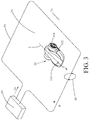
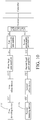
- the automatic working system as shown in Fig. 3 comprises a signal generating device 80, configured to generate a current signal SS; a boundary wire 50, forming an electric loop with the signal generating device 80, wherein the signal generating device 80 generates the boundary signal SS as shown in Fig. 2 and sends to the boundary wire 50, and the boundary signal SS generates a changed magnetic field 90 when flowing through the boundary wire 50.
- the boundary signal SS can also adopt a periodic pulse voltage signal as not shown in Fig. 2 , and other types of signal forms which can generate a changed magnetic field can also be adopted.
- the boundary wire 50 is used for dividing a specific region into an inside region and an outside region, wherein a range located in the boundary wire 50 is defined as a working region 30, and a range located outside the boundary wire 50 is defined as a non-working region 70.
- the automatic working system also comprises an automatic moving device 10, which automatically moves and works in the working region 30 planned by the boundary wire 50, the automatic moving device 10 comprises at least one detecting device, as shown in Fig. 4 , the automatic moving device 10 comprises a detecting device 110, and also comprises an adjusting module 140 and a comparing module, wherein, the comparing module is electrically connected to the adjusting module 140, and preferably disposed in the processor 130, and can also be disposed outside the processor 130 according to needs and electrically connected to the processor 130; at least one detecting device 110 detects the electromagnetic field 50 to generate at least one detection signal; the adjusting module 140 amplifies the at least one detection signal to form at least one gain signal; the comparing module compares at least one extreme point of the gain signal with a preset condition, and the preset condition comprises that the extreme point is lower than an upper threshold value and higher than a lower threshold value; if the extreme point is higher than the upper threshold value, then the adjusting module 140 reduces an amplification factor of the gain signal, and if the
- the extreme point in the preset point comprises a peak value and/or a valley value.
- the adjusting module 140 adjusts the amplification factor of the gain signal.
- the preset condition is preferably disposed in the processor 130, it is understandable that the preset condition can also be not disposed in the processor 130, is disposed in other positions of the automatic moving device, and is fed back into the processor 130 through a circuit. The preset condition is described in detail in the following text.
- the upper threshold value and the lower threshold value can be fixed values and can be adjusted according to different conditions.
- the automatic moving device 10 can be an automatic or semi-automatic machine such as an intelligent mower, or a cleaning robot.
- the intelligent mower is taken as an example of the automatic moving device 10.
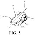
- the automatic moving device 10 comprises a shell 102, a plurality of wheels 104 located on the bottom of the shell 102, a motor located in the shell 102 (not shown), and a processor and a controller which control the automatic moving device 10 to automatically work and automatically walk (not shown).
- the quantity of the motors can be one or more, and the motor is configured to drive the wheels 104 to move or drive a working part (not shown) of the automatic moving device 10 to mow.
- the detecting device 110 of the automatic moving device 10 is an inductance coil.
- the inductance coil 110 is usually vertically disposed on the automatic moving device 10, such that an effective area of the electromagnetic field 90 sensed by the inductance coil 110 is the largest, the effective area is an area vertical to a direction of the magnetic field.
- the inductance coil can also be disposed on the automatic moving device 10 non-vertically, for example, disposed on the automatic moving device 10 by 75°and 45° and other different angles. No matter the inductance coil is disposed on the automatic moving device 10 in which angle, only the condition that the inductance coil has an effective area and can sense to generate the detection signal needs to be guaranteed.
- the automatic moving device 10 can comprise a plurality of detecting devices, which detect the electromagnetic field 90 to generate a plurality of corresponding detection signals respectively, as shown in Fig. 5 , the automatic moving device 10 comprises a first detecting device 1101 and a second detecting device 1102.
- the first detecting device 1101 and the second detecting device 1102 respectively detect a change of the magnetic field 90 to generate a first detection signal and a second detection signal.
- the first detecting device 1101 and the second detecting device 1102 are respectively located at two sides of a middle axis Y of the automatic moving device 10, specifically symmetric about the middle axis Y for example.
- the first detecting device 1101 and the second detecting device 1102 can also be located in other positions of the automatic moving device 10.
- the positions of the first detecting device 1101 and the second detecting device 1102 are symmetric about the middle axis of the two charging docking terminals.
- the first detecting device 1101 and the second detecting device 1102 are respectively located at different sides of the motor, specifically, for example, the first detecting device 1101 is located at the right side of the motor and the second detecting device 1102 is located at the left side of the motor.
- the automatic moving device 10 comprises more than or equal to two detecting devices
- a specific position of each detecting device on the automatic moving device 10 can have many choices. Specifically, when the automatic moving device 10 comprises three detecting devices, two of which are located at left and right sides of the symmetric axis respectively, and the last detecting device is located at some point on the symmetric axis. The embodiments about the setting of the specific positions are too many and are not repeated in the description.
- the automatic moving device 10 having one detecting device is taken as an embodiment for detailed description in the following text.
- the present embodiment performs analog-digital conversion on the detected detection signal, and then adopts a digital signal processor to perform denoising.
- a digital signal processor to perform denoising.
- the denoising in the present embodiment can be realized by using a corresponding hardware circuit.
- the detecting device 110 of the automatic moving device can be electrically connected to one offset device 120 as required, the offset device 120 can be electrically connected to a processor 130, which comprises a differential analog to digital converter 150 electrically connected to the adjusting module 140 and the comparing module and having a memory space, and the processor 130 also comprises a controller 160 electrically connected to the differential analog to digital converter 150.
- the differential analog to digital converter 150 can also not be provided with a memory, and the processor 130 is provided with the memory space for storing a digital signal.
- the type of the processor 130 is for example ST MICROPROCESSOR.
- the detecting device 110 detects a signal in the environment to form a detection signal ST1, the signal in the environment comprises a boundary signal transmitted by the boundary wire and signals transmitted not by the boundary wire, and the signals transmitted not by the boundary wire mainly comprise interference signals of adjacent working systems and a noise interference signal in the environment, etc.
- the offset device 120 can upward offset, downward offset or fix the whole of the detection signal ST1 relative to a zero point, in one determined embodiment, one of the manners is selected to process the detection signal ST1, it needs to be pointed out that when the detection signal ST1 is upward offset, downward offset or fixed relative to the zero point, the setting of numbers of the upper threshold value and the lower threshold value in the preset condition is also correspondingly moved according to movement of the detection signal, and the upper threshold value and the lower threshold value are described in detail in the following text.
- the detection signal ST1 through the offset device 120 is input to the adjusting module 140 and forms a gain signal SG1 through adjusting, the comparing module compares an extreme point of the gain signal SG1 with the preset condition, according to a comparing result, the adjusting module 140 adjusts an amplification factor of the gain signal SG1, such that the adjusted gain signal SG1 accords with the preset condition, the differential analog to digital converter 150 converts the gain signal SG1 accords with the preset condition into a digital signal SD1, the processor 130 also internally comprises a denoising module and a judging module, the denoising module removes an interference signal in the digital signal SD1 according to a denoising algorithm, for example, an interference signal of the adjacent system, a noise interference signal in the environment, an interference signal of the motor, etc., the judging module judges whether the detecting device 110 is in or outside the boundary wire based on the denoised digital signal SD1, and sends a moving signal to the controller 160, and the controller 160 drives the automatic moving device 10 to move
- the controller 160 sends a corresponding control command to the automatic moving device 10 based on the moving signal sent from the processor 130. For example, when the detecting device 110 does not detect an effective signal, then the controller 160 does not send any action command, such that the automatic moving device 10 does not walk any more; when the detecting device 110 is in the non-working region, then the controller 160 sends a command to make the automatic moving device 10 get away from the non-working region.
- the specific control command is designed by a user or designer self according to different results obtained from processing, and therefore, a logic therein is not repeated.
- the processor 130 can adopt different extreme points to compare with the preset condition, for example, adopt a peak value of the gain signal SG1 to compare with the preset condition, or adopt a valley value of the gain signal SG1 to compare with the preset signal, such that the peak value or valley value of the gain signal SG1 accords with the preset condition, or the peak value and valley value of the gain signal SG1 are adopted to compare with the preset condition at the same time, and when one of the peak value and the valley value of the gain signal SG1 does not accord with the preset condition, the adjusting module 140 will adjust the gain signal SG1, such that the peak value and valley value of the gain signal SG1 accord with the preset condition at the same time.
- the preset condition preset by the processor 130 comprises: in the direction of the peak value, a peak value Peak-Pos of the gain signal SG1 is higher than a lower threshold value VL1 and lower than an upper threshold value VU1.
- the adjusting module 140 reduces an amplification factor of the gain signal SG1, if the adjusted gain signal SG1 is still higher than the upper threshold value VU1, then the adjusting module 140 continues to reduce the amplification factor of the gain signal SG1 till the peak value Peak-Pos of the gain signal SG1 is lower than the upper threshold value VU1 and higher than the lower threshold value VL1.
- the comparing module compares, if the peak value Peak-Pos of the gain signal SG1 is lower than the lower threshold value VL1, then the an amplification factor of the gain signal SG1 is increased, if the adjusted gain signal SG1 is still lower than the lower threshold value VL1, then the adjusting module 140 continues to increase the amplification factor of the gain signal SG1 till the peak value Peak-Pos of the gain signal SG1 is higher than the lower threshold value VL1 and lower than the upper threshold value VU1.
- the process of adjusting the valley value Peak-Neg of the gain signal SG1 is similar to that of adjusting the peak value Peak-Pos of the gain signal SG1 and is not repeated herein.
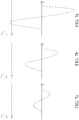
- a sensitivity threshold value can be disposed in the direction of the peak value Peak-Pos of the gain signal SG1 or the direction of the valley value Peak-Neg of the gain signal SG1, the quantity and position of the sensitivity threshold value are not defined, different quantities and different positions can be set according to an actual condition, as shown in Fig.
- a first sensitivity threshold value VM1 is disposed in the direction of the peak value Peak-Pos of the gain signal SG1, if the peak value Peak-Pos of the gain signal SG1 is higher than the upper threshold value VU1 and also higher than the first sensitivity value VM1, then the adjusting module 140 can reduce the amplification factor of the gain SG1 by two times according to an internal algorithm to make the peak value Peak-Pos be lower than the upper threshold value VU1, if there is no first sensitivity threshold value VM1, then the adjusting module 140 reduces the gain signal SG1 by one time, after reduced by one time, if the peak value Peak-Pos is still higher than the upper threshold value VU1, the adjusting module 140 reduces the gain SG1 by one time again till the peak value Peak-Pos is lower than the upper threshold value VU1, due to the setting of the sensitivity threshold value, the adjusting module 140 can directly adjust the amplification factor accords with the preset condition instead of adjusting the gain
- a second sensitivity threshold value VM2 can be disposed below the lower threshold value VL1, and the amplification factor of the adjusting module 140 is decided according to a fact whether the peak value Peak-Pos is lower than the second sensitivity threshold value VM2 or intersected with the second sensitivity threshold value VM2 when lower than the lower threshold value VL1.
- the sensitivity threshold value can be disposed in different positions in the direction of the peak value of the gain signal SG1, and the quantity and position of the sensitivity threshold values are not limited.
- the sensitivity threshold values of unlimited quantities and positions can be set according to different conditions, and it is similar to the setting principle in the direction of the peak value Peak-Pos of the gain signal SG1, and is not repeated herein.
- the extreme point of the gain signal SG1 may not be directly adopted to compare with the preset condition, according to a preprocessing condition, a feature point of the gain signal SG1 is found, the feature point of the gain signal SG1 is adopted to compare with the preset condition, the preprocessing condition comprises that the feature point of the gain signal SG1 is a point in a function relation with the extreme point of the gain signal SG1, for example, the feature point is a point at a 2/3 position of the extreme point, a point at a 4/5 position of the extreme point or the extreme point, and the extreme point is a peak value or valley value of the gain signal SG1.
- the preset condition of the feature point when select the feature point which is in a function relation with an extreme point of the gain signal SG1 to compare with the preset condition, the preset condition of the feature point also make a corresponding adjustment according to the selected function relation .
- the upper threshold value VU1' and the lower threshold value VL1' as 2/3 times of the upper threshold value VU1 and the lower threshold value VL1,That is, the upper threshold value VU1' in preset condition of the feature point is 2/3VU1, the lower threshold value VL1' is 2/3VL1.
- the setting of the adjusting module 140 has many implementing manners.
- the adjusting module 140 comprises a programmable gain amplifier (PGA) 1401 in a processor 130 and also comprises a fixed gain amplifier 1402, connected to the PGA 1401, outside processor 130, the amplification factor of the fixed gain amplifier 1402 is fixed, for example, a value between 100-200 times, such that the detecting device 110 can always detect the boundary signal in the working region, the PGA 1401 in the processor 130 automatically adjusts the gain signal SG1 amplified by the fixed gain amplifier 1402 according to a feedback of the adjusting module, such that the adjusted gain signal SG1 accords with the preset condition, therefore, the denoising step and the step of judging effectiveness of the gain signal SG1 are further performed according to needs.
- PGA programmable gain amplifier
- the quantity of levels of the PGA 1401 can be one of 2-6, the amplification factor is 1/2 to 16 times that of the gain signal SG1, and the amplification factor is in the above range, such that after amplified, the gain signal SG1 can be sampled and received by the differential analog to digital converter 150 always, if the gain signal SG1 is amplified to much, then the gain signal may get out of the range of the input signal of the differential analog to digital converter 150.
- the quantity of the levels of the PGA 1401 are 5, and the amplification factor is 1/2 to 8 times of the gain signal, specifically, 1/2, 1, 2, 4 and 8 times.
- the adjusting module 1401 is a PGA, which is disposed in the processor 130, and the PGA automatically adjusts the amplification factor of the gain signal SG1 according to the feedback of the comparing module, such that the adjusted gain signal SG1 accords with the preset condition.
- levels of the PGA can be one of 2-6, and the amplification factor is 1/2 to 16 times that of the gain signal SG1. Most preferably, the quantity of the levels of the PGA are 5, and the amplification factor is 1/2 to 8 times of the gain signal, specifically, 1/2, 1, 2, 4 and 8 times.
- a difference from the second manner is that the PGA is disposed outside the processor, one end of the PGA is connected to an output end of an offset device 120, and the other end of the PGA is connected to an input end of the processor 130, and is not repeated herein.
- the first detecting device 1101 and the second detecting device 1102 respectively detect the boundary signal to generate a first detection signal ST1' and a second detection signal ST2', the process flow of the first detection signal ST1' and that of the second detection signal ST2' are similar, therefore, the processing flow of any one of the first detection signal ST1' and the second detection signal ST2' is the same as that of the detection signal ST1 by adopting one detecting device 110, and the structure constitution and principle are similar,and are not repeated herein.
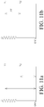
- a sampling manner is not limited, a common analog to digital converter or a differential analog to digital converter can be adopted, as shown in Fig. 11a , in the sampling process of the common analog to digital converter, a method of obtaining the detection signal of the detecting device comprises obtaining a voltage V1 of an inductance soil relative to a grounding end, then obtaining an interference voltage V2 of the detecting device relative to the grounding end, and V1 and V2 are subjected to a method of difference to obtain ⁇ V, which is a voltage value of the detection signal.
- a method of obtaining the voltage value of the detection signal of the detecting device comprises: directly obtaining the differential value ⁇ V of V2 and V1, and the method is simple and can filter the interference of the grounding end.
- a sampling frequency of the differential analog to digital converter 150 of the present invention is 50KHz
- the adjusted gain signal is sampled every 20us to obtain a corresponding digital amplitude value
- the differential analog to digital converter 150 can store 700 value points every time, the corresponding time is 14ms, therefore, in the present embodiment, a processing period of a denoising control algorithm is 14ms, that is, an index period corresponding to the digital signal is 700 points.
- the processing period can be changed according to a used hardware or adding a limiting condition. Therefore, the processing period does not limit the present invention.
- the type of the differential analog to digital converter 150 of the present invention is for example SDADC. Other types of analog to digital converters can also be adopted.
- An optimal filter is also disposed in the processor 130, can filter a harmonic signal different from the boundary signal 50 in frequency, and improves a signal to noise ratio to the greatest degree.
- the automatic working system provided in the present invention can filter the interference signal weaker than the boundary signal according to the setting of the upper threshold value and the lower threshold value to achieve the denoising aim, other denoising modules can also be disposed in the processor 130 as required, for example, the automatic working system can be combined with a product algorithm described in the international patent application with an application number PCT/CN2016/104718 for use, and the interference signal can be filtered to the greatest degree by combined use. A specific algorithm described in this patent application document is not repeated.
- the effective signal output from the processor 130 can be used for judging that the automatic moving device 10 is in or outside the working region, and a distance between the automatic moving device and the boundary wire can be judged by using the strength of the effective signal. Further, by means of the distance between the automatic moving device and the boundary wire, a working route of the automatic moving device or a route of returning back to the charging station is planned, therefore, and a damage to a lawn is avoided.
- the automatic working system of the present invention is not only suitable for a small range working region, but also suitable for a large range working region (for example, an area of the working region 30 is larger than 4000 square meter).
Landscapes
- Engineering & Computer Science (AREA)
- Physics & Mathematics (AREA)
- Radar, Positioning & Navigation (AREA)
- Remote Sensing (AREA)
- General Physics & Mathematics (AREA)
- Automation & Control Theory (AREA)
- Aviation & Aerospace Engineering (AREA)
- Electromagnetism (AREA)
- Control Of Position, Course, Altitude, Or Attitude Of Moving Bodies (AREA)
- Business, Economics & Management (AREA)
- Health & Medical Sciences (AREA)
- Artificial Intelligence (AREA)
- Evolutionary Computation (AREA)
- Game Theory and Decision Science (AREA)
- Medical Informatics (AREA)
Applications Claiming Priority (4)
| Application Number | Priority Date | Filing Date | Title |
|---|---|---|---|
| CN201611131568 | 2016-12-09 | ||
| CN201611194236 | 2016-12-21 | ||
| CN201611262890.9A CN108227692A (zh) | 2016-12-09 | 2016-12-30 | 自动移动设备、自动工作系统及其控制方法 |
| PCT/CN2017/070182 WO2018103178A1 (zh) | 2016-12-09 | 2017-01-04 | 自动移动设备、自动工作系统及其控制方法 |
Publications (3)
| Publication Number | Publication Date |
|---|---|
| EP3553470A1 true EP3553470A1 (de) | 2019-10-16 |
| EP3553470A4 EP3553470A4 (de) | 2021-01-13 |
| EP3553470B1 EP3553470B1 (de) | 2022-10-26 |
Family
ID=62658126
Family Applications (1)
| Application Number | Title | Priority Date | Filing Date |
|---|---|---|---|
| EP17700031.2A Active EP3553470B1 (de) | 2016-12-09 | 2017-01-04 | Automatische mobile vorrichtung, automatisches arbeitssystem und steuerungsverfahren dafür |
Country Status (3)
| Country | Link |
|---|---|
| US (1) | US11106215B2 (de) |
| EP (1) | EP3553470B1 (de) |
| CN (1) | CN108227692A (de) |
Families Citing this family (18)
| Publication number | Priority date | Publication date | Assignee | Title |
|---|---|---|---|---|
| CN109871012B (zh) * | 2019-01-29 | 2022-04-12 | 宁波大叶园林设备股份有限公司 | 一种智能割草机在边界处的转向方法 |
| CN112824937B (zh) * | 2019-11-20 | 2024-05-28 | 苏州宝时得电动工具有限公司 | 一种路线生成方法、装置和割草机 |
| CN111142516A (zh) * | 2019-12-12 | 2020-05-12 | 南京苏美达智能技术有限公司 | 一种用于确定自行走设备工作区域的交互系统、基站及方法 |
| CN113552874B (zh) * | 2020-04-03 | 2024-01-23 | 南京泉峰科技有限公司 | 智能割草系统 |
| CN112158543A (zh) * | 2020-09-03 | 2021-01-01 | 贵州翰凯斯智能技术有限公司 | 一种智慧城市生活服务系统和使用方法 |
| CN114510014B (zh) * | 2020-10-26 | 2024-08-06 | 莱克电气绿能科技(苏州)有限公司 | 自动移动设备的边界识别方法、装置及存储介质 |
| CN114578803B (zh) * | 2020-11-30 | 2025-03-25 | 莱克电气绿能科技(苏州)有限公司 | 自动行走设备及其回归控制方法 |
| CN114637281B (zh) * | 2020-11-30 | 2024-11-29 | 莱克电气绿能科技(苏州)有限公司 | 自动行走设备及其边界信号检测方法 |
| US12296694B2 (en) | 2021-03-10 | 2025-05-13 | Techtronic Cordless Gp | Lawnmowers |
| US12443180B2 (en) | 2021-11-10 | 2025-10-14 | Techtronic Cordless Gp | Robotic lawn mowers |
| AU2023200381A1 (en) | 2022-01-31 | 2023-08-17 | Techtronic Cordless Gp | Robotic garden tool |
| EP4270138A1 (de) | 2022-04-28 | 2023-11-01 | Techtronic Cordless GP | Erzeugung einer virtuellen grenze für ein robotisches gartenwerkzeug |
| US12472611B2 (en) | 2022-05-31 | 2025-11-18 | Techtronic Cordless Gp | Peg driver |
| EP4310621B1 (de) | 2022-07-19 | 2025-02-12 | Techtronic Cordless GP | Anzeige zur steuerung eines robotischen werkzeugs |
| AU2023206123A1 (en) | 2022-07-29 | 2024-02-15 | Techtronic Cordless Gp | Generation of a cryptography key for a robotic garden tool |
| EP4660734A4 (de) * | 2023-02-03 | 2026-05-06 | Zhejiang Sunseeker Ind Co Ltd | Autonome betriebsvorrichtung, steuerungsverfahren dafür und autonomes betriebssystem |
| CN116541691B (zh) * | 2023-05-05 | 2023-12-22 | 杭州轨物科技有限公司 | 一种用于自动行走设备的抗干扰检测边界线信号的方法 |
| CN117055395A (zh) * | 2023-08-17 | 2023-11-14 | 湖南迈克森伟电子科技有限公司 | 远程无线声控开关系统 |
Family Cites Families (16)
| Publication number | Priority date | Publication date | Assignee | Title |
|---|---|---|---|---|
| US6798197B2 (en) * | 2002-10-08 | 2004-09-28 | Zetec, Inc. | Dynamic gain control in a digital eddy current signal processor |
| US7313378B2 (en) * | 2003-11-26 | 2007-12-25 | Starkey Laboratories, Inc. | Tracking automatic gain control |
| US7706917B1 (en) * | 2004-07-07 | 2010-04-27 | Irobot Corporation | Celestial navigation system for an autonomous robot |
| US8972052B2 (en) * | 2004-07-07 | 2015-03-03 | Irobot Corporation | Celestial navigation system for an autonomous vehicle |
| CN100466467C (zh) * | 2004-12-02 | 2009-03-04 | 上海交通大学 | 具有自动增益控制功能的音量自动限幅装置 |
| CN101420209B (zh) | 2008-11-21 | 2011-08-31 | 北京时代民芯科技有限公司 | 一种高速大动态范围数字化自动增益控制电路 |
| US8352113B2 (en) * | 2010-07-28 | 2013-01-08 | Deere & Company | Robotic mower boundary coverage system |
| CN202126267U (zh) | 2011-06-15 | 2012-01-25 | 江汉大学 | 电子测量装置 |
| CN102889850A (zh) | 2011-07-18 | 2013-01-23 | 上海热流环境科技有限公司 | 割草机器人边界识别方法 |
| CN102723923B (zh) * | 2012-06-19 | 2014-11-19 | 深圳数字电视国家工程实验室股份有限公司 | 一种自动增益控制方法及装置 |
| CN103543745B (zh) | 2012-07-16 | 2016-12-21 | 苏州宝时得电动工具有限公司 | 导引系统及其控制方法 |
| JP6307748B2 (ja) | 2014-10-21 | 2018-04-11 | 本田技研工業株式会社 | 自律走行作業車の制御装置 |
| JP6014182B2 (ja) | 2015-02-10 | 2016-10-25 | 本田技研工業株式会社 | 自律走行作業車の制御装置 |
| WO2016184398A1 (zh) | 2015-05-19 | 2016-11-24 | 苏州宝时得电动工具有限公司 | 边界线的脉冲信号识别系统、方法及智能割草系统 |
| US10379172B2 (en) * | 2015-06-05 | 2019-08-13 | Irobot Corporation | Magnetic field localization and navigation |
| CN106130579B (zh) * | 2016-07-01 | 2018-06-15 | 波达通信设备(广州)有限公司 | 毫米波发射机的增益自动控制方法及装置 |
-
2016
- 2016-12-30 CN CN201611262890.9A patent/CN108227692A/zh active Pending
-
2017
- 2017-01-04 EP EP17700031.2A patent/EP3553470B1/de active Active
-
2019
- 2019-06-05 US US16/432,433 patent/US11106215B2/en active Active
Also Published As
| Publication number | Publication date |
|---|---|
| US20190286158A1 (en) | 2019-09-19 |
| EP3553470A4 (de) | 2021-01-13 |
| CN108227692A (zh) | 2018-06-29 |
| US11106215B2 (en) | 2021-08-31 |
| EP3553470B1 (de) | 2022-10-26 |
Similar Documents
| Publication | Publication Date | Title |
|---|---|---|
| US11106215B2 (en) | Automatic moving device, automatic working system and control method thereof | |
| WO2018103178A1 (zh) | 自动移动设备、自动工作系统及其控制方法 | |
| CN106843199B (zh) | 自动工作系统及其控制方法及自动行走设备 | |
| CN108536136B (zh) | 自动行走设备以及边界距离检测方法、装置和系统 | |
| EP2487785A2 (de) | Stromrichter mit Reduzierung der Gleichtaktspannung | |
| SE2050416A1 (en) | Robotic working tool system and method for defining a working area | |
| CN106909143A (zh) | 自移动机器人系统 | |
| CN107818563B (zh) | 一种输电线路分裂导线间距空间测量与定位方法 | |
| CN104883042A (zh) | 一种充电机输出电压纹波的处理方法及装置 | |
| CN111358359B (zh) | 机器人的避线方法、装置、芯片及扫地机器人 | |
| CN120439284A (zh) | 一种工业机器人智能路径规划方法与系统 | |
| CN110320563B (zh) | 感应装置、折叠架及折叠家具 | |
| CN201974698U (zh) | 一种机器人行动区域设定系统 | |
| CN104753324B (zh) | 避免输入滤波器谐振的装置及方法 | |
| CN205883108U (zh) | 一种抗冲击载荷的伺服控制器 | |
| Chen et al. | Highly Efficient Smart 3-Coil Wireless Power Transfer System with Automatic Tracking | |
| CN114679046A (zh) | 功率因数校正的载波频率控制方法、控制装置和空调器 | |
| JP6098629B2 (ja) | 電力変換装置 | |
| CN223998430U (zh) | 一种机械臂控制系统 | |
| CN219846351U (zh) | 扫地机的控制电路及扫地机 | |
| CN114275163A (zh) | 折叠臂模组、喷洒设备、及驱动方法 | |
| CN210882659U (zh) | 一种基于电磁定位的无人机及无人机系统 | |
| US11967892B2 (en) | DC power supply device and servo DC power supply system | |
| CN113119762B (zh) | 一种水下电磁寻充方法 | |
| CN111358360A (zh) | 机器人避免线缠绕的方法、装置和芯片及扫地机器人 |
Legal Events
| Date | Code | Title | Description |
|---|---|---|---|
| STAA | Information on the status of an ep patent application or granted ep patent |
Free format text: STATUS: UNKNOWN |
|
| STAA | Information on the status of an ep patent application or granted ep patent |
Free format text: STATUS: THE INTERNATIONAL PUBLICATION HAS BEEN MADE |
|
| PUAI | Public reference made under article 153(3) epc to a published international application that has entered the european phase |
Free format text: ORIGINAL CODE: 0009012 |
|
| STAA | Information on the status of an ep patent application or granted ep patent |
Free format text: STATUS: REQUEST FOR EXAMINATION WAS MADE |
|
| 17P | Request for examination filed |
Effective date: 20190627 |
|
| AK | Designated contracting states |
Kind code of ref document: A1 Designated state(s): AL AT BE BG CH CY CZ DE DK EE ES FI FR GB GR HR HU IE IS IT LI LT LU LV MC MK MT NL NO PL PT RO RS SE SI SK SM TR |
|
| AX | Request for extension of the european patent |
Extension state: BA ME |
|
| DAV | Request for validation of the european patent (deleted) | ||
| DAX | Request for extension of the european patent (deleted) | ||
| R17P | Request for examination filed (corrected) |
Effective date: 20190627 |
|
| A4 | Supplementary search report drawn up and despatched |
Effective date: 20201216 |
|
| RIC1 | Information provided on ipc code assigned before grant |
Ipc: G05D 1/02 20200101ALI20201210BHEP Ipc: G01C 21/00 20060101AFI20201210BHEP |
|
| STAA | Information on the status of an ep patent application or granted ep patent |
Free format text: STATUS: EXAMINATION IS IN PROGRESS |
|
| 17Q | First examination report despatched |
Effective date: 20210928 |
|
| GRAP | Despatch of communication of intention to grant a patent |
Free format text: ORIGINAL CODE: EPIDOSNIGR1 |
|
| STAA | Information on the status of an ep patent application or granted ep patent |
Free format text: STATUS: GRANT OF PATENT IS INTENDED |
|
| INTG | Intention to grant announced |
Effective date: 20220512 |
|
| GRAS | Grant fee paid |
Free format text: ORIGINAL CODE: EPIDOSNIGR3 |
|
| GRAA | (expected) grant |
Free format text: ORIGINAL CODE: 0009210 |
|
| STAA | Information on the status of an ep patent application or granted ep patent |
Free format text: STATUS: THE PATENT HAS BEEN GRANTED |
|
| RIN1 | Information on inventor provided before grant (corrected) |
Inventor name: CONTI, EMANUEL Inventor name: DALFRA, DAVIDE |
|
| AK | Designated contracting states |
Kind code of ref document: B1 Designated state(s): AL AT BE BG CH CY CZ DE DK EE ES FI FR GB GR HR HU IE IS IT LI LT LU LV MC MK MT NL NO PL PT RO RS SE SI SK SM TR |
|
| REG | Reference to a national code |
Ref country code: GB Ref legal event code: FG4D |
|
| REG | Reference to a national code |
Ref country code: CH Ref legal event code: EP |
|
| REG | Reference to a national code |
Ref country code: AT Ref legal event code: REF Ref document number: 1527322 Country of ref document: AT Kind code of ref document: T Effective date: 20221115 |
|
| REG | Reference to a national code |
Ref country code: DE Ref legal event code: R096 Ref document number: 602017062968 Country of ref document: DE |
|
| REG | Reference to a national code |
Ref country code: IE Ref legal event code: FG4D |
|
| REG | Reference to a national code |
Ref country code: SE Ref legal event code: TRGR |
|
| REG | Reference to a national code |
Ref country code: LT Ref legal event code: MG9D |
|
| REG | Reference to a national code |
Ref country code: NL Ref legal event code: MP Effective date: 20221026 |
|
| REG | Reference to a national code |
Ref country code: AT Ref legal event code: MK05 Ref document number: 1527322 Country of ref document: AT Kind code of ref document: T Effective date: 20221026 |
|
| PG25 | Lapsed in a contracting state [announced via postgrant information from national office to epo] |
Ref country code: NL Free format text: LAPSE BECAUSE OF FAILURE TO SUBMIT A TRANSLATION OF THE DESCRIPTION OR TO PAY THE FEE WITHIN THE PRESCRIBED TIME-LIMIT Effective date: 20221026 |
|
| PG25 | Lapsed in a contracting state [announced via postgrant information from national office to epo] |
Ref country code: PT Free format text: LAPSE BECAUSE OF FAILURE TO SUBMIT A TRANSLATION OF THE DESCRIPTION OR TO PAY THE FEE WITHIN THE PRESCRIBED TIME-LIMIT Effective date: 20230227 Ref country code: NO Free format text: LAPSE BECAUSE OF FAILURE TO SUBMIT A TRANSLATION OF THE DESCRIPTION OR TO PAY THE FEE WITHIN THE PRESCRIBED TIME-LIMIT Effective date: 20230126 Ref country code: LT Free format text: LAPSE BECAUSE OF FAILURE TO SUBMIT A TRANSLATION OF THE DESCRIPTION OR TO PAY THE FEE WITHIN THE PRESCRIBED TIME-LIMIT Effective date: 20221026 Ref country code: FI Free format text: LAPSE BECAUSE OF FAILURE TO SUBMIT A TRANSLATION OF THE DESCRIPTION OR TO PAY THE FEE WITHIN THE PRESCRIBED TIME-LIMIT Effective date: 20221026 Ref country code: ES Free format text: LAPSE BECAUSE OF FAILURE TO SUBMIT A TRANSLATION OF THE DESCRIPTION OR TO PAY THE FEE WITHIN THE PRESCRIBED TIME-LIMIT Effective date: 20221026 Ref country code: AT Free format text: LAPSE BECAUSE OF FAILURE TO SUBMIT A TRANSLATION OF THE DESCRIPTION OR TO PAY THE FEE WITHIN THE PRESCRIBED TIME-LIMIT Effective date: 20221026 |
|
| PG25 | Lapsed in a contracting state [announced via postgrant information from national office to epo] |
Ref country code: RS Free format text: LAPSE BECAUSE OF FAILURE TO SUBMIT A TRANSLATION OF THE DESCRIPTION OR TO PAY THE FEE WITHIN THE PRESCRIBED TIME-LIMIT Effective date: 20221026 Ref country code: PL Free format text: LAPSE BECAUSE OF FAILURE TO SUBMIT A TRANSLATION OF THE DESCRIPTION OR TO PAY THE FEE WITHIN THE PRESCRIBED TIME-LIMIT Effective date: 20221026 Ref country code: LV Free format text: LAPSE BECAUSE OF FAILURE TO SUBMIT A TRANSLATION OF THE DESCRIPTION OR TO PAY THE FEE WITHIN THE PRESCRIBED TIME-LIMIT Effective date: 20221026 Ref country code: IS Free format text: LAPSE BECAUSE OF FAILURE TO SUBMIT A TRANSLATION OF THE DESCRIPTION OR TO PAY THE FEE WITHIN THE PRESCRIBED TIME-LIMIT Effective date: 20230226 Ref country code: HR Free format text: LAPSE BECAUSE OF FAILURE TO SUBMIT A TRANSLATION OF THE DESCRIPTION OR TO PAY THE FEE WITHIN THE PRESCRIBED TIME-LIMIT Effective date: 20221026 Ref country code: GR Free format text: LAPSE BECAUSE OF FAILURE TO SUBMIT A TRANSLATION OF THE DESCRIPTION OR TO PAY THE FEE WITHIN THE PRESCRIBED TIME-LIMIT Effective date: 20230127 |
|
| P01 | Opt-out of the competence of the unified patent court (upc) registered |
Effective date: 20230608 |
|
| REG | Reference to a national code |
Ref country code: DE Ref legal event code: R097 Ref document number: 602017062968 Country of ref document: DE |
|
| PG25 | Lapsed in a contracting state [announced via postgrant information from national office to epo] |
Ref country code: SM Free format text: LAPSE BECAUSE OF FAILURE TO SUBMIT A TRANSLATION OF THE DESCRIPTION OR TO PAY THE FEE WITHIN THE PRESCRIBED TIME-LIMIT Effective date: 20221026 Ref country code: RO Free format text: LAPSE BECAUSE OF FAILURE TO SUBMIT A TRANSLATION OF THE DESCRIPTION OR TO PAY THE FEE WITHIN THE PRESCRIBED TIME-LIMIT Effective date: 20221026 Ref country code: EE Free format text: LAPSE BECAUSE OF FAILURE TO SUBMIT A TRANSLATION OF THE DESCRIPTION OR TO PAY THE FEE WITHIN THE PRESCRIBED TIME-LIMIT Effective date: 20221026 Ref country code: DK Free format text: LAPSE BECAUSE OF FAILURE TO SUBMIT A TRANSLATION OF THE DESCRIPTION OR TO PAY THE FEE WITHIN THE PRESCRIBED TIME-LIMIT Effective date: 20221026 Ref country code: CZ Free format text: LAPSE BECAUSE OF FAILURE TO SUBMIT A TRANSLATION OF THE DESCRIPTION OR TO PAY THE FEE WITHIN THE PRESCRIBED TIME-LIMIT Effective date: 20221026 |
|
| PG25 | Lapsed in a contracting state [announced via postgrant information from national office to epo] |
Ref country code: SK Free format text: LAPSE BECAUSE OF FAILURE TO SUBMIT A TRANSLATION OF THE DESCRIPTION OR TO PAY THE FEE WITHIN THE PRESCRIBED TIME-LIMIT Effective date: 20221026 Ref country code: AL Free format text: LAPSE BECAUSE OF FAILURE TO SUBMIT A TRANSLATION OF THE DESCRIPTION OR TO PAY THE FEE WITHIN THE PRESCRIBED TIME-LIMIT Effective date: 20221026 |
|
| REG | Reference to a national code |
Ref country code: CH Ref legal event code: PL |
|
| PLBE | No opposition filed within time limit |
Free format text: ORIGINAL CODE: 0009261 |
|
| STAA | Information on the status of an ep patent application or granted ep patent |
Free format text: STATUS: NO OPPOSITION FILED WITHIN TIME LIMIT |
|
| PG25 | Lapsed in a contracting state [announced via postgrant information from national office to epo] |
Ref country code: LU Free format text: LAPSE BECAUSE OF NON-PAYMENT OF DUE FEES Effective date: 20230104 |
|
| REG | Reference to a national code |
Ref country code: BE Ref legal event code: MM Effective date: 20230131 |
|
| 26N | No opposition filed |
Effective date: 20230727 |
|
| PG25 | Lapsed in a contracting state [announced via postgrant information from national office to epo] |
Ref country code: LI Free format text: LAPSE BECAUSE OF NON-PAYMENT OF DUE FEES Effective date: 20230131 Ref country code: CH Free format text: LAPSE BECAUSE OF NON-PAYMENT OF DUE FEES Effective date: 20230131 |
|
| PG25 | Lapsed in a contracting state [announced via postgrant information from national office to epo] |
Ref country code: SI Free format text: LAPSE BECAUSE OF FAILURE TO SUBMIT A TRANSLATION OF THE DESCRIPTION OR TO PAY THE FEE WITHIN THE PRESCRIBED TIME-LIMIT Effective date: 20221026 Ref country code: BE Free format text: LAPSE BECAUSE OF NON-PAYMENT OF DUE FEES Effective date: 20230131 |
|
| PG25 | Lapsed in a contracting state [announced via postgrant information from national office to epo] |
Ref country code: IE Free format text: LAPSE BECAUSE OF NON-PAYMENT OF DUE FEES Effective date: 20230104 |
|
| PG25 | Lapsed in a contracting state [announced via postgrant information from national office to epo] |
Ref country code: IT Free format text: LAPSE BECAUSE OF FAILURE TO SUBMIT A TRANSLATION OF THE DESCRIPTION OR TO PAY THE FEE WITHIN THE PRESCRIBED TIME-LIMIT Effective date: 20221026 |
|
| PG25 | Lapsed in a contracting state [announced via postgrant information from national office to epo] |
Ref country code: MC Free format text: LAPSE BECAUSE OF FAILURE TO SUBMIT A TRANSLATION OF THE DESCRIPTION OR TO PAY THE FEE WITHIN THE PRESCRIBED TIME-LIMIT Effective date: 20221026 |
|
| PG25 | Lapsed in a contracting state [announced via postgrant information from national office to epo] |
Ref country code: MC Free format text: LAPSE BECAUSE OF FAILURE TO SUBMIT A TRANSLATION OF THE DESCRIPTION OR TO PAY THE FEE WITHIN THE PRESCRIBED TIME-LIMIT Effective date: 20221026 |
|
| PG25 | Lapsed in a contracting state [announced via postgrant information from national office to epo] |
Ref country code: BG Free format text: LAPSE BECAUSE OF FAILURE TO SUBMIT A TRANSLATION OF THE DESCRIPTION OR TO PAY THE FEE WITHIN THE PRESCRIBED TIME-LIMIT Effective date: 20221026 |
|
| PG25 | Lapsed in a contracting state [announced via postgrant information from national office to epo] |
Ref country code: BG Free format text: LAPSE BECAUSE OF FAILURE TO SUBMIT A TRANSLATION OF THE DESCRIPTION OR TO PAY THE FEE WITHIN THE PRESCRIBED TIME-LIMIT Effective date: 20221026 |
|
| PGFP | Annual fee paid to national office [announced via postgrant information from national office to epo] |
Ref country code: DE Payment date: 20250116 Year of fee payment: 9 |
|
| PGFP | Annual fee paid to national office [announced via postgrant information from national office to epo] |
Ref country code: SE Payment date: 20250128 Year of fee payment: 9 |
|
| PGFP | Annual fee paid to national office [announced via postgrant information from national office to epo] |
Ref country code: FR Payment date: 20250130 Year of fee payment: 9 |
|
| PGFP | Annual fee paid to national office [announced via postgrant information from national office to epo] |
Ref country code: GB Payment date: 20250123 Year of fee payment: 9 |
|
| PG25 | Lapsed in a contracting state [announced via postgrant information from national office to epo] |
Ref country code: CY Free format text: LAPSE BECAUSE OF FAILURE TO SUBMIT A TRANSLATION OF THE DESCRIPTION OR TO PAY THE FEE WITHIN THE PRESCRIBED TIME-LIMIT; INVALID AB INITIO Effective date: 20170104 |
|
| PG25 | Lapsed in a contracting state [announced via postgrant information from national office to epo] |
Ref country code: HU Free format text: LAPSE BECAUSE OF FAILURE TO SUBMIT A TRANSLATION OF THE DESCRIPTION OR TO PAY THE FEE WITHIN THE PRESCRIBED TIME-LIMIT; INVALID AB INITIO Effective date: 20170104 |
|
| PG25 | Lapsed in a contracting state [announced via postgrant information from national office to epo] |
Ref country code: TR Free format text: LAPSE BECAUSE OF FAILURE TO SUBMIT A TRANSLATION OF THE DESCRIPTION OR TO PAY THE FEE WITHIN THE PRESCRIBED TIME-LIMIT Effective date: 20221026 |