EP3553466A1 - Method for analyzing the surface quality of composite laminates - Google Patents
Method for analyzing the surface quality of composite laminates Download PDFInfo
- Publication number
- EP3553466A1 EP3553466A1 EP19164717.1A EP19164717A EP3553466A1 EP 3553466 A1 EP3553466 A1 EP 3553466A1 EP 19164717 A EP19164717 A EP 19164717A EP 3553466 A1 EP3553466 A1 EP 3553466A1
- Authority
- EP
- European Patent Office
- Prior art keywords
- built
- laminate part
- fibers
- elevation
- locations
- Prior art date
- Legal status (The legal status is an assumption and is not a legal conclusion. Google has not performed a legal analysis and makes no representation as to the accuracy of the status listed.)
- Granted
Links
Images




Classifications
-
- G—PHYSICS
- G01—MEASURING; TESTING
- G01B—MEASURING LENGTH, THICKNESS OR SIMILAR LINEAR DIMENSIONS; MEASURING ANGLES; MEASURING AREAS; MEASURING IRREGULARITIES OF SURFACES OR CONTOURS
- G01B11/00—Measuring arrangements characterised by the use of optical techniques
- G01B11/24—Measuring arrangements characterised by the use of optical techniques for measuring contours or curvatures
-
- B—PERFORMING OPERATIONS; TRANSPORTING
- B29—WORKING OF PLASTICS; WORKING OF SUBSTANCES IN A PLASTIC STATE IN GENERAL
- B29C—SHAPING OR JOINING OF PLASTICS; SHAPING OF MATERIAL IN A PLASTIC STATE, NOT OTHERWISE PROVIDED FOR; AFTER-TREATMENT OF THE SHAPED PRODUCTS, e.g. REPAIRING
- B29C64/00—Additive manufacturing, i.e. manufacturing of three-dimensional [3D] objects by additive deposition, additive agglomeration or additive layering, e.g. by 3D printing, stereolithography or selective laser sintering
- B29C64/30—Auxiliary operations or equipment
- B29C64/386—Data acquisition or data processing for additive manufacturing
-
- B—PERFORMING OPERATIONS; TRANSPORTING
- B29—WORKING OF PLASTICS; WORKING OF SUBSTANCES IN A PLASTIC STATE IN GENERAL
- B29C—SHAPING OR JOINING OF PLASTICS; SHAPING OF MATERIAL IN A PLASTIC STATE, NOT OTHERWISE PROVIDED FOR; AFTER-TREATMENT OF THE SHAPED PRODUCTS, e.g. REPAIRING
- B29C66/00—General aspects of processes or apparatus for joining preformed parts
- B29C66/90—Measuring or controlling the joining process
-
- B—PERFORMING OPERATIONS; TRANSPORTING
- B29—WORKING OF PLASTICS; WORKING OF SUBSTANCES IN A PLASTIC STATE IN GENERAL
- B29C—SHAPING OR JOINING OF PLASTICS; SHAPING OF MATERIAL IN A PLASTIC STATE, NOT OTHERWISE PROVIDED FOR; AFTER-TREATMENT OF THE SHAPED PRODUCTS, e.g. REPAIRING
- B29C70/00—Shaping composites, i.e. plastics material comprising reinforcements, fillers or preformed parts, e.g. inserts
- B29C70/04—Shaping composites, i.e. plastics material comprising reinforcements, fillers or preformed parts, e.g. inserts comprising reinforcements only, e.g. self-reinforcing plastics
- B29C70/28—Shaping operations therefor
- B29C70/30—Shaping by lay-up, i.e. applying fibres, tape or broadsheet on a mould, former or core; Shaping by spray-up, i.e. spraying of fibres on a mould, former or core
- B29C70/38—Automated lay-up, e.g. using robots, laying filaments according to predetermined patterns
- B29C70/382—Automated fiber placement [AFP]
-
- B—PERFORMING OPERATIONS; TRANSPORTING
- B29—WORKING OF PLASTICS; WORKING OF SUBSTANCES IN A PLASTIC STATE IN GENERAL
- B29C—SHAPING OR JOINING OF PLASTICS; SHAPING OF MATERIAL IN A PLASTIC STATE, NOT OTHERWISE PROVIDED FOR; AFTER-TREATMENT OF THE SHAPED PRODUCTS, e.g. REPAIRING
- B29C70/00—Shaping composites, i.e. plastics material comprising reinforcements, fillers or preformed parts, e.g. inserts
- B29C70/04—Shaping composites, i.e. plastics material comprising reinforcements, fillers or preformed parts, e.g. inserts comprising reinforcements only, e.g. self-reinforcing plastics
- B29C70/28—Shaping operations therefor
- B29C70/54—Component parts, details or accessories; Auxiliary operations, e.g. feeding or storage of prepregs or SMC after impregnation or during ageing
-
- B—PERFORMING OPERATIONS; TRANSPORTING
- B32—LAYERED PRODUCTS
- B32B—LAYERED PRODUCTS, i.e. PRODUCTS BUILT-UP OF STRATA OF FLAT OR NON-FLAT, e.g. CELLULAR OR HONEYCOMB, FORM
- B32B27/00—Layered products comprising a layer of synthetic resin
- B32B27/18—Layered products comprising a layer of synthetic resin characterised by the use of special additives
- B32B27/26—Layered products comprising a layer of synthetic resin characterised by the use of special additives using curing agents
-
- G—PHYSICS
- G01—MEASURING; TESTING
- G01B—MEASURING LENGTH, THICKNESS OR SIMILAR LINEAR DIMENSIONS; MEASURING ANGLES; MEASURING AREAS; MEASURING IRREGULARITIES OF SURFACES OR CONTOURS
- G01B21/00—Measuring arrangements or details thereof, where the measuring technique is not covered by the other groups of this subclass, unspecified or not relevant
- G01B21/30—Measuring arrangements or details thereof, where the measuring technique is not covered by the other groups of this subclass, unspecified or not relevant for measuring roughness or irregularity of surfaces
-
- G—PHYSICS
- G01—MEASURING; TESTING
- G01N—INVESTIGATING OR ANALYSING MATERIALS BY DETERMINING THEIR CHEMICAL OR PHYSICAL PROPERTIES
- G01N21/00—Investigating or analysing materials by the use of optical means, i.e. using sub-millimetre waves, infrared, visible or ultraviolet light
- G01N21/84—Systems specially adapted for particular applications
-
- G—PHYSICS
- G06—COMPUTING OR CALCULATING; COUNTING
- G06F—ELECTRIC DIGITAL DATA PROCESSING
- G06F30/00—Computer-aided design [CAD]
- G06F30/10—Geometric CAD
- G06F30/17—Mechanical parametric or variational design
-
- G—PHYSICS
- G06—COMPUTING OR CALCULATING; COUNTING
- G06F—ELECTRIC DIGITAL DATA PROCESSING
- G06F30/00—Computer-aided design [CAD]
- G06F30/20—Design optimisation, verification or simulation
-
- G—PHYSICS
- G01—MEASURING; TESTING
- G01N—INVESTIGATING OR ANALYSING MATERIALS BY DETERMINING THEIR CHEMICAL OR PHYSICAL PROPERTIES
- G01N21/00—Investigating or analysing materials by the use of optical means, i.e. using sub-millimetre waves, infrared, visible or ultraviolet light
- G01N21/84—Systems specially adapted for particular applications
- G01N2021/8472—Investigation of composite materials
Definitions
- This disclosure relates to a method of analyzing the surface quality of a laminate part, and more particularly, identifying the location of a surface anomaly with respect to locations of fibers within the laminate part.
- tools for analyzing the surface quality of a composite laminate part which locate a surface anomaly as well as the internal fiber locations within the laminate part which contribute to surface anomalies. These tools include non-destructive inspection procedures and destructive inspection procedures.
- Non-destructive inspection procedures can include use of the transmission of ultrasound or x-ray waves to internally scan the laminate part. This non-destructive inspection involves expensive equipment. The inspection can also require long lead times for analysis. The resolution for such non-destructive inspection is not always to a level so as to extract precise defects and their locations. These non-destructive inspections which utilize transmission of ultrasound or x-ray waves can also introduce systematic noise into the analysis by way of the inspection requires these wave transmissions to scan through layers of composite laminate material.
- a destructive inspection procedure for a laminate part includes destruction of a coupon cutout of the part being inspected and requires high resolution scanning of cross sections of the laminate part. This procedure not only has the drawback of requiring the destruction of the part for the analysis but also has a further drawback in that the user is receiving a two dimensional ("2D") analysis of a single slice of the laminate part at a time. This analysis of a single slice at a time can be difficult to understand the anomaly which needs three dimensional (“3D”) analysis.
- 2D two dimensional
- An example includes a method for analyzing a surface quality of a laminate part which includes the steps of creating a planned dimensioned representation of a laminate part desired to be built which includes a first surface having a first topography and placing fibers into locations for the laminate part desired to be built. The method further includes the step of curing a resin associated with the placed fibers fabricating an as-built laminate part from the planned dimensioned representation of the laminate part desired to be built which includes a second surface having a second topography which corresponds to the first surface having the first topography.
- steps of aligning the first surface, the second surface and the locations of the fibers determining a first elevation of a first point on the first surface and a second elevation of a second point on the second surface; and observing the first surface, the second surface and the locations of the fibers in alignment and the first elevation relative to the second elevation in analyzing the surface quality of the laminate part.
- An example includes a computer-implemented method for analyzing a surface quality of a laminate part including the steps of receiving, by a processor, a data file which contains a planned dimensioned representation of a laminate part desired to be built which includes a first surface with first topographic data of the first surface and receiving, by a processor, a data file which contains locations of fibers for the laminate part desired to be built.
- the method further includes the step receiving, by a processor, a data file from a scan performed on a second surface having second topographic data, of an as-built laminate part fabricated from the planned dimensioned representation of the laminate part desired to be built, wherein the as-built laminate part was fabricated having fibers with fiber locations based on the data file which contains the locations of fibers for the laminate part desired to be built and the second surface corresponds to the first surface.
- the method further includes the step of aligning, by a processor, the first surface which includes first topographic data of the first surface from the data file which contains the planned dimensioned representation of the laminate part desired to be built; the second surface which includes second topographic data of the second surface from the data file which contains data from the scan performed on the second surface of the as-built laminate part; and the location of the fibers for the laminate part desired to be built from the data file which contains the locations of the fibers within the laminate part desired to be built.
- the method further includes the step of causing to be presented to a user via a display a visual representation representing the first surface, the second surface and the locations of fibers in alignment and an indication of the first elevation relative to the second elevation, in analyzing the surface quality of the laminate part.
- Laminate parts can be made of one of numerous shapes and contours so as to accommodate an assembly to which the laminate part may be incorporated.
- the designer may need to alter the position of fiber locations within plies of the laminate part to be built from a standard configuration of generally parallel spacing of fibers within a ply.
- This alteration of fiber locations from the standard configuration can include incorporating in locations an increased spacing between adjacent fibers within a ply of the laminate part to be built and/or include incorporating an overlap in locations of adjacent fibers within a ply of the laminate part to be built.
- the resulting fabricated as-built laminate part can result in having surface anomalies.
- the designer may, as mentioned above, need to alter locations of fibers within a ply which deviate from standard configuration of fibers which includes fibers spaced apart and extending generally parallel to one another within the ply.
- one ply may have an overlap of adjacent fibers within that ply which in turn aligns with an overlap of adjacent fibers within another ply.
- This alignment configuration of overlapping fibers can result in an anomaly of a protrusion being positioned on the surface of the as-built or cured laminate part. The protrusion would be a deviation from a surface of the planned dimensioned representation of the laminate part desired to be built.
- the elevation difference in the protrusion in the surface of the as-built laminate part with respect to the elevation of the surface of the planned dimensioned representation of the laminate part desired to be built may or may not be within a tolerance range that is acceptable for the intended use of the as-built laminate part.
- the tolerance range may take into account the need to provide an appropriate bonding surface or fit of the as-built laminate part with respect to another part within an assembly in which the as-built part is incorporated.
- plies which overlie one another within the laminate part to be built may have location(s) of adjacent fibers within a ply which are positioned at an increased spacing from the standard configuration of adjacent fibers and is aligned with an increased spacing of adjacent fibers from the standard configuration in another ply.
- the alignment configuration of these increased spacing of adjacent fibers in different plies can result in an anomaly of a recess being positioned on the surface of the fabricated as-built or cured laminate part.
- the elevation difference in the recess in the surface of the as-built laminate part that has been cured with respect to the elevation of the surface of the planned dimensioned representation of the laminate part desired to be built may or may not be within a tolerance range that is acceptable for the intended use of the as-built laminate part.
- the tolerance range may take into account the need to provide an appropriate bonding surface or fit of the as-built laminate part with respect to another part in an assembly in which the as-built part is incorporated.
- an inexpensive and reliable analytical tool would be helpful in analyzing the fiber configuration locations within a laminate part and the surface anomalies that are associated with the particular fiber configurations.
- the analytical tool described herein can provide the developer or fabricator an inexpensive and reliable methodology, which does not introduce systematic noise, to identify an anomaly and to identify fiber locations that influence the anomaly.
- the analytical tool can provide the developer or fabricator the ability to alter locations of fibers within the laminate part to be built, if needed, to optimally bring an anomaly that may be in excess of a tolerance back within tolerance such that production of the laminate part serves its intended function.
- a dashed line format is used to show a planned dimensioned representation of the laminate part 10P (10-prime) desired to be built.
- Planned dimensioned representation of the laminate part 10P desired to be built is generally designed in advance of fabricating a corresponding as-built laminate part 10 as seen in FIG. 1 represented in a solid line format.
- reference 10 identifies an as-built laminate part while reference 10P identifies the desired "to be built" laminate part.
- planned dimensioned representation of the laminate part 10P desired to be built is placed within a computer aided design (CAD) file.
- CAD computer aided design
- the planned dimensioned representation of the laminate part 10P desired to be built sets forth the planned dimensions of the laminate part 10P desired to be built and provides data with respect, for example, to a first topography of first surface 12P as well as topography information for other surfaces with respect to laminate part 10P desired to be built.
- planned dimensioned representation of laminate part 10P also includes the number of and thickness of plies 14P.
- the planned dimensioned representation of laminate part 10P desired to be built provides the dimensions and ideal topographical data for surfaces of the as-built laminate part 10, as seen in FIG. 1 .
- the planned dimensioned representation of the laminate part 10P desired to be built does not include any fibers and therefore there are no fiber locations within the planned dimensioned representation of the laminate part 10P desired to be built.
- the planned dimensioned representation of the laminate 10P desired to be built does not have any anomalies on any surface such as for example first surface 12P which in contrast otherwise can appear in second surface 12 of as-built laminate part 10 as a result of particular fiber locations being positioned within plies 14 of as-built laminate part 10 as discussed above.
- as-built laminate part 10 was constructed from the design of planned dimensioned representation of the laminate part 10P desired to be built along with the placement of fibers within locations of the laminate part 10P desired to be built.
- the planned representation of the laminate part 10P desired to be built does not include fibers.
- the locations of fibers which result in as-built laminate part 10, in this example, is provided to a numerical control (not shown) which directs the operation of an automated fiber placement machine (not shown) used in constructing as-built laminate part 10.
- this assembly is cured and as-built laminate part 10 is fabricated.
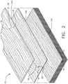
- as-built laminate part 10 is shown with three plies 14A, 14B and 14C in an exploded perspective view.
- An exemplary standard configuration 16 of fibers 18 which extend along ply 14C a distance D is shown.
- Other fibers 18 which deviate from standard configuration 16 will be discussed in more detail below.
- a flow chart for method 20 for analyzing a surface quality of a laminate part is shown.
- Method 20 will be discussed below along with a computer-implemented embodiment of this method for analyzing the surface quality of a laminate part with respect to the schematic block diagram of a laminate part surface quality analyzing system 46 of FIG. 5 .
- Analyzing a surface quality of a laminate part includes identifying and quantifying contour deviations within a surface of a fabricated laminate part in comparison to a corresponding surface of an ideal design for the laminate part.
- the analyzing includes identifying and ascertaining whether surface deviations on the fabricated laminate part, such as a recess or protrusion, is within an acceptable tolerance for the surface to be acceptable for optimally, for example, bonding the surface to a surface of another part.
- the analysis provides identification of the location of fibers within the fabricated laminate part and within the vicinity of the surface deviation so as to provide an opportunity to ascertain adjustments being made to fiber locations for a subsequent fabrication of the part in order to mitigate the surface deviation and provide a surface within the acceptable tolerance of a subsequently fabricated laminate part.
- method 20 for analyzing a surface quality of a laminate part includes step 22 of creating a planned dimensioned representation of a laminate part 10P desired to be built which includes a first surface 12P having a first topography as shown in FIG. 1 .
- the planned dimensioned representation of the laminate part 10P desired to be built which includes first surface 12P having first topography is placed in this example into a CAD file.
- Method 20 further includes step 24 of placing fibers into locations for laminate part 10P desired to be built.
- planned dimensioned representation of laminate part 10P desired to be built does not include fibers does have dimensions and contour configurations that are ideal for the ultimately fabricated as-built laminate part 10.
- Step 24 of placing of fibers into locations for the laminate part 10P desired to be built further includes in this example placing at least two adjacent fibers within at least one ply of the laminate part 10P desired to be built such that at least two adjacent fibers deviate from the standard configuration which are fibers spaced apart and extending generally parallel to one another within a ply. Examples of deviations from standard configuration 16 can be seen in FIG. 2 of as-built laminate part 10.
- Step 24 of placing of fibers into locations for laminate part 10P desired to be built further includes in this example an increased spacing 26 between the at least two adjacent fibers 18 of the at least one ply 14A from standard configuration 16 as seen in FIG. 2 of as-built laminate part 10.
- Step 24 of placing of fibers into locations for the laminate part 10P desired to be built further includes in this example an overlap of at least two adjacent fibers 18 of the at least one ply 14B as seen in FIG. 2 of as-built laminate part 10.
- method 20 further includes step 30 of curing a resin associated with the placed fibers 18 fabricating an as-built laminate part 10 from the planned dimensioned representation of the laminate part 10P desired to be built which includes second surface 12 having a second topography as seen in FIG. 1 , which corresponds to first surface 12P having first topography.
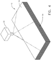
- Step 30 of curing further includes scanning second surface 12, as shown in FIG. 4 , to obtain the second topography of second surface 12. Scanning in this example is generally conducted with a laser scanner 32 which provides digital data of the second topography of second surface 12 which will be discussed below.
- Method 20 for analyzing a surface quality of a laminate part of FIG. 3 further includes step 34 of aligning first surface 12P, second surface 12 and the locations of the fibers.
- This step 34 will be discussed in further detail below in the discussion of the computer-implemented method for analyzing the surface quality of a laminate part.
- digital data is available for first surface 12P and the topography of first surface 12P such as provided to CAD as well as a digital data representation of the locations of the fibers in various plies is available as was provided to the numerical control for the automated fiber placement machine used in constructing an as-built laminate part 10.
- the scanning by laser scanner 32 provides digital data of the second surface 12 having second topography of second surface 12.
- Step 34 of aligning first surface 12P having the first topography from planned dimensioned representation of the laminate part 10P desired to be built; second surface 12 which has the second topography and the locations of the fibers includes: first surface 12P, second surface 12 and the locations of fibers all have a common horizontal plane H of reference (as seen for example positioned between laminate part 10P to be built and as-built laminate part 10 of FIG. 1 ) and a common vertical plane V of reference (not shown in FIG. 1 but would extend perpendicular in relationship to the common horizontal plane H of reference).
- first surface 12P, second surface 12 and the locations of fibers having a common horizontal plane H of reference and a common vertical plane V of reference they are aligned such that comparisons between elevations on first surface 12P and second surface 12 can be easily made as well as determining the location of the fibers with respect to the elevation comparisons between first surface 12P and second surface 12. This will be further discussed herein and in the computer-implemented method.
- Method 20 further includes step 36 of determining the first elevation of first point 38 on first surface 12P and the second elevation of second point 40 on second surface 12, as schematically identified in FIG. 1 , wherein first and second points 38, 40 have a common point 42 of reference in common horizontal plane H of reference. With first surface 12P and second surface 12 aligned in the common horizontal plane H of reference and having the same common point 42 of reference, first point 38 and second point 40 are at the same location with respect to first surface 12P and second surface 12 respectively.
- Determining first elevation of first point 38 on first surface 12P and second elevation of second point 40 on second surface 12 includes in one example to position both planned representation of laminate part 10P desired to be built and as-built laminate part 10 aligned in the same position at a same common elevation in the common vertical plane V of reference.
- a measurement can be taken from the a common reference elevation on the vertical plane V of reference to first point 38 and provide a first elevation and a measurement can be taken from the common reference elevation on the vertical plane V of reference to second point 40 and provide a second elevation.
- the subtraction of first and second elevations will provide a difference in elevation between the first and second points 38, 40.
- second point 40 on second surface 12 of as-built laminate part 10 can be used for optimally bonding to a surface of another part in fabricating an assembly to which as-built part 10 is incorporated. Should the difference in elevation fall outside the predetermined range for an acceptable tolerance, as-built laminate part will not be used in fabricating the assembly. Repositioning of fiber locations may be performed for mitigating the elevation difference so as to conform the surface of the laminate part to be within the acceptable tolerance for fabricating a subsequent laminate part.
- Method 20 further includes step 44 of observing first surface 12P, second surface 12 and the locations of the fibers in alignment and first elevation of first point 38 relative to second elevation of second point 40.
- step 44 of observing first surface 12P, second surface 12 and the locations of the fibers in alignment and first elevation of first point 38 relative to second elevation of second point 40.
- Step 44 of observing further includes a step of altering location of at least one fiber for the laminate part 10P desired to be built in response to any difference in elevation observed between the first elevation and the second elevation which exceeds a tolerance range.
- a tolerance range is predetermined by the designer or fabricator so as to provide the proper bonding surface or fit for second surface 12 with respect to other part(s) of an assembly to which as-built laminate part 10 and second surface 12 will be incorporated.
- the altering of locations of fibers 18 can mitigate a recess or protrusion deviation that can be positioned on an as-built laminate part and provide the surface of a subsequent fabricated as-built laminate part to be within an acceptable tolerance and be optimal in bonding or fitting with respect to an assembly to which it may be incorporated.
- System 46 includes computing device 48.
- Computing device 48 includes memory 50 and processor 52.
- Computing device 48 can take any one of a number of configurations and in this configuration computing device 48 includes memory 50 which includes storing non-transitory computer readable instructions in a tangible medium as well as temporary memory and processor 52 executes computer readable instructions.
- this computing device 48 one or more microprocessors can be included.
- An I/O circuit 58 also in this computing device 48, is shown as one block but it should be appreciated I/O circuit 58 may include a number of different types of I/O circuits.
- Memory 50, processor 52 and I/O circuit 58 are all interconnected via an address/data bus 60. Further included within computing device 48 are input device 62 and output display device 64.
- input device 62 can include one or more keyboard(s), mouse(s) and/or touch screen(s) as well as other common input devices and output display device 64 can include one or more commonly known visual display devices. Both input device 62 and output display device 64 are connected in this example to I/O circuit 58.
- Laminate part surface quality analyzing system 46 in this example further includes numerical control 66 which will receive data files of locations of fibers for laminate part 10P desired to be built, in this example from memory 50, wherein numerical control 66 will in turn be connected to an automated fiber placement machine (not shown) which will place fibers for plies 14 in fabricating as-built laminate part 10 in accordance with the data files received by numerical control 66.
- System 46 in this example, further includes scanner 32, which as earlier mentioned in this example, is a laser scanner which is utilized to scan as-built laminate part 10, as seen in FIG. 4 , and provide topographic data of a surface, such as for second surface 12, to processor 52. This is one of many variations of system 46 which can be employed to run computer-implemented method for analyzing the surface quality of a laminate part.
- Computer-implemented method for analyzing the surface quality of a laminate part can be operated on a laminate part surface quality analyzing system 46, such as described above wherein computer-implemented method includes the step of receiving, by processor 52, a data file which contains a planned dimensioned representation of a laminate part 10P desired to be built which includes first surface 12P with first topographic data of first surface 12P. This data file does not include fiber location data.
- the user can design planned dimension representation of a laminate part 10P desired to be built by way of inputting data from input device 62 to processor 52 in preparing a CAD file which is stored in memory 50. Further included is a step of receiving, by processor 52, a data file which contains locations of fibers for the laminate part 10P desired to be built.
- This data for data file in this example can have originated from input device 62 wherein the user designed the locations of fibers to be positioned in each ply for fabricating as-built laminate part 10.
- This data can, for example, be stored in memory 50 and available to be transmitted to numerical control 66 which instructs the automated fiber placement machine (not shown) to properly place fibers for each ply for laminate part 10P desired to be built for fabrication of as-built laminate part 10.
- the computer-implemented method includes a step of receiving by processor 52 the data file which contains the locations of fibers within the laminate part desired to be built 10P further includes identifying the location of any deviation from a standard configuration between adjacent fibers, as mentioned earlier, positioned in each ply of the laminate part 10P desired to be built for fabrication of as-built laminate part 10.
- the data file further includes identifying the location of an increased spacing 26 from standard configuration 16 between two adjacent fibers 18 within at least one ply such as seen in ply 14A of FIG. 2 .
- the data file further includes identifying a location of an overlap 28 of two adjacent fibers 18 within at least one ply such as seen in ply 14B as seen in FIG. 2 .
- Computer-implemented method further includes a step of receiving, by processor 52, a data file from a scan performed by scanner 32 which was performed on second surface 12 having second topographic data, of an as-built laminate part 10 fabricated from planned dimensioned representation of the laminate part 10P desired to be built.
- As-built laminated part 10 was fabricated having fibers with fiber locations based on the data file which contains the locations of fibers for the laminate part desired to be built 10P and second surface 12 corresponds to first surface 12P.
- Computer-implemented method further includes a step of aligning, by processor 52, first surface 12P which includes first topographic data of first surface 12P from the data file which contains the planned dimensioned representation of the laminate part desired to be built 10P; second surface 12 which includes second topographic data of second surface 12 from the data file which contains data from the scan performed on second surface 12 of as-built laminate part 10; and the location of the fibers for laminate part desired to be built 10P from the data file which contains the locations of the fibers within the laminate part desired to be built 10P.
- the scan performed as discussed earlier includes performing the scan, in this example, with laser scanner 32 as shown in FIG. 4 and providing processor 52 with the data which can be stored in memory 50.
- the step of aligning further includes aligning first surface 12P, second surface 12 and the locations of the fibers within the laminate part 10P desired to be built with respect to a common horizontal plane H of reference, as shown for example in FIG. 1 , and a common vertical plane V of reference (not shown).
- a representative horizontal plane H of reference can be seen in FIG. 1 wherein first point 38 and second point 40 have a common point of reference 42 in common horizontal plane H of reference.
- first point 38 and second point 40 are the same location with respect to planned dimensioned representation of the laminate part desired to be built 10P and as-built laminate part 10, respectively.
- Common vertical plane V of reference is (not shown), is oriented perpendicular to horizontal plane H of reference.
- Computer-implemented method further includes a step of determining, by processor 52, first elevation of first point 38 on first surface 12P and second elevation of second point 40 on second surface 12 as seen in FIG. 1 .
- First point 38 is from the data file which contains planned dimensioned representation of the laminate part 10P desired to be built which includes first surface 12P with first topographic data.
- Second point 40 is from the data file from the scan performed on second surface 12 having second topographic data of second surface 12 of as-built laminate part 10.
- the step of determining includes the first and second points 38, 40 have a common point of reference 42 in common horizontal plane H of reference which reflects that first point 38 and second point 40 are in the same location with respect to the horizontal plane H of reference with respect to planned dimensioned representation of laminate part 10P to be built and as-built laminate part 10 respectively.
- determining the first elevation of first point 38 on first surface 12P and the second elevation of second point 40 on second surface 12 includes in one example to position both representation of laminate part 10P desired to be built and as-built laminate part 10 aligned at a same common elevation in the common vertical plane V of reference.
- a measurement can be taken from a common reference elevation on the vertical plane V of reference to first point 38 and provide a first elevation and a measurement can be taken from the common reference elevation on the vertical plane V of reference to the second point 40 and provide a second elevation.
- the subtraction of first and second elevations will provide a difference in elevation between the first and second points 38, 40. All of this can be computed by processor 52.
- processor 52 can compute measurements from the same common reference elevation of common vertical plane V of reference and should those measurements be the same to first point 38 and to second point 40, there would be no difference in the measurements or between first and second elevations thereby indicating there is no deviation or anomaly in existence at second point 40 of second surface 12 of as-built laminate part 10 relative to first point 38 of first surface 12P.
- Computer-implemented method further includes a step of causing to be presented to a user via a display 64 a visual representation which represents first surface 12P, second surface 12 and the locations of fibers in alignment and an indication of the first elevation relative to the second elevation.
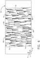
- the locations of fibers are seen in output display device 64 in FIG. 6 .
- the horizontal plane H of reference is shown by way of two arrows designated as H which extend perpendicular to one another and a vertical plane V of reference is designated by V which indicates an arrow which extends perpendicular relative to horizontal plane H.
- digital representations of locations of fibers for the laminate part 10P desired to be built which is fabricated as as-built laminate part 10 are shown positioned in various plies 14.
- This data would be data used to fabricate as-built laminate part 10 in utilizing numerical control 66 used to operate the automated fiber placement machine in the fabrication of as-built laminate part 10.
- the blank triangular forms 68 schematically represent the position of adjacent fibers 18 which are positioned in an increased spacing 26 as seen in FIG. 2 and the shaded triangular forms 70 schematically represent the position of adjacent fibers 18 in an overlap 28 position as also seen in FIG. 2 .
- the view in display device 64 provides a representative view of the fiber locations within as-built laminate part 10.
- locations of fibers 18 are shown as set forth for example in FIG. 6 .
- the dashed triangular forms 68P schematically represent the position of adjacent fibers 18 which are positioned in an increased spacing 26 as seen in FIG. 2
- the solid triangular forms 70P schematically represent the position of adjacent fibers 18 in an overlap 28 position.
- first surface 12P with topographic data for first surface 12P second surface 12 with topographic data for second surface 12 and locations of fibers 18 in alignment in display 64 in FIG. 7 having a common horizontal plane H of reference and a common vertical plane V of reference.
- Display 64 also shows an indication of the first elevation relative to the second elevation which in this example ranges of differences of first and second elevations will be indicated by different shading or color coding wherein different colors designate predetermined range of difference in elevation between the first and second elevations.
- first elevation and second elevation for first and second points 38 and 40 respectively, this can be done with numerous corresponding points on first surface 12P first topography and second surface 12 second topography. This would provide an indication of the differences between the first topography and the second topography of first and second surfaces 12P and 12 respectively.
- Predetermined ranges of differences in elevation such as for example between first elevation and second elevation, can be indicated on display 64 by way of color coding or use of different colors such that a particular color will designate a predetermined range of difference in elevation between first elevation and second elevation.
- different grades of shading are provided instead of different colors indicating a different predetermined range of difference in elevation between for example first elevation and second elevation and for corresponding points such as first point 38 and second point 40. With a region of first surface 12P and second surface 12 having a difference in elevation of corresponding points in first surface 12P and second surface 12 that falls within a predetermined range, the color or the shading will be the same.
- region of shading 72 indicates a slight variation, or small range of difference in elevation between corresponding on first surface 12P of planned dimensioned representation of laminate part 10P desired to be built and second surface 12 of as-built laminate part 10 such as first point 38 and second point 40.
- the user will be indicated by the shading or coloring that there is no concern for anomalies in second surface 12 that are in this difference in elevation range between first surface 12P of laminate part 10P desired to be built and second surface 12 of as-built laminate part 10 such that any altering of locations of fibers is not needed and that region of shading 72 with respect to second surface 12 is acceptable for purposes of bonding and/or fit with other components within an assembly in which as-built laminate part is to be incorporated.
- the color coding or shading differences also provides the user the indication of the difference in elevation with respect to second surface 12 as to whether that region is in a recess position or protrusion position relative to first surface 12P.
- different shading 74 which has slightly darker shading 74 than shading 72 (or of a different color) indicates a greater further variation in the difference first elevations of first point 38 of first surface 12P and that of second elevation of second point 40 of second surface 12 and such corresponding points between first surface 12P and second surface 12.
- This shading 74 also indicates there are no anomalies or deviations that need to be addressed in that region with respect to second surface 12 and therefore no changes in locations of fibers need to be made in that area.
- this region of different shading 74 (or coloring) is to be further reviewed should alterations of locations of fibers be made to check whether the tolerance becomes exceeded.
- the surface of as-built laminate part 10 in that region is acceptable for purposes of bonding and/or fit with other components within an assembly in which as-built laminate part 10 is to be incorporated.
- Darker shading 76 (or a different color) which is a darker shading than shading 74 indicates a further variation in the difference of first point 38 first elevation of first surface 12P and that of second elevation of second point 40 of second surface 12 such that corresponding points and their first and second elevations in this region are outside of a predetermined acceptable tolerance range.
- the user will need to look at the fiber locations and see what alterations of locations of fibers can be made so as to mitigate the anomaly or deviation on second surface 12 for a subsequent as-built laminate part is constructed.
- the user can go through the process of fabricating a subsequent as-built laminate part 10 and place this subsequent as-built laminate part 10 through the above analysis and check to see if the anomalies or deviations have been mitigated and are now within the acceptable tolerance such that as-built laminate part 10 is ready for production.
Landscapes
- Engineering & Computer Science (AREA)
- Physics & Mathematics (AREA)
- General Physics & Mathematics (AREA)
- Chemical & Material Sciences (AREA)
- Mechanical Engineering (AREA)
- Geometry (AREA)
- Theoretical Computer Science (AREA)
- Composite Materials (AREA)
- Materials Engineering (AREA)
- General Engineering & Computer Science (AREA)
- Computer Hardware Design (AREA)
- Evolutionary Computation (AREA)
- Health & Medical Sciences (AREA)
- Pathology (AREA)
- Biochemistry (AREA)
- Immunology (AREA)
- General Health & Medical Sciences (AREA)
- Analytical Chemistry (AREA)
- Life Sciences & Earth Sciences (AREA)
- Robotics (AREA)
- Mathematical Analysis (AREA)
- Mathematical Optimization (AREA)
- Computational Mathematics (AREA)
- Pure & Applied Mathematics (AREA)
- Manufacturing & Machinery (AREA)
- Optics & Photonics (AREA)
- Moulding By Coating Moulds (AREA)
- Laminated Bodies (AREA)
Abstract
Description
- This disclosure relates to a method of analyzing the surface quality of a laminate part, and more particularly, identifying the location of a surface anomaly with respect to locations of fibers within the laminate part. There are currently very limited tools for analyzing the surface quality of a composite laminate part which locate a surface anomaly as well as the internal fiber locations within the laminate part which contribute to surface anomalies. These tools include non-destructive inspection procedures and destructive inspection procedures.
- Non-destructive inspection procedures can include use of the transmission of ultrasound or x-ray waves to internally scan the laminate part. This non-destructive inspection involves expensive equipment. The inspection can also require long lead times for analysis. The resolution for such non-destructive inspection is not always to a level so as to extract precise defects and their locations. These non-destructive inspections which utilize transmission of ultrasound or x-ray waves can also introduce systematic noise into the analysis by way of the inspection requires these wave transmissions to scan through layers of composite laminate material.
- A destructive inspection procedure for a laminate part includes destruction of a coupon cutout of the part being inspected and requires high resolution scanning of cross sections of the laminate part. This procedure not only has the drawback of requiring the destruction of the part for the analysis but also has a further drawback in that the user is receiving a two dimensional ("2D") analysis of a single slice of the laminate part at a time. This analysis of a single slice at a time can be difficult to understand the anomaly which needs three dimensional ("3D") analysis.
- Thus, there is a need to provide for a non-destructive inspection analysis which does not require excessive costs and time expended associated with the equipment, the inspection and the analysis. There is also a need to provide a high resolution inspection to provide precision in locating a defect or anomaly in the surface and fiber locations within the laminate part which are proximate to the anomaly, since the existence of the surface defect or anomaly can be as a result of the fiber locations positioned beneath the surface of the laminate part and within the vicinity of the anomaly. There is also a need to avoid the introduction of systematic noise which can be introduced by wave transmissions that may be used to internally scan a laminate part
- An example includes a method for analyzing a surface quality of a laminate part which includes the steps of creating a planned dimensioned representation of a laminate part desired to be built which includes a first surface having a first topography and placing fibers into locations for the laminate part desired to be built. The method further includes the step of curing a resin associated with the placed fibers fabricating an as-built laminate part from the planned dimensioned representation of the laminate part desired to be built which includes a second surface having a second topography which corresponds to the first surface having the first topography. Further included are the steps of aligning the first surface, the second surface and the locations of the fibers; determining a first elevation of a first point on the first surface and a second elevation of a second point on the second surface; and observing the first surface, the second surface and the locations of the fibers in alignment and the first elevation relative to the second elevation in analyzing the surface quality of the laminate part.
- An example includes a computer-implemented method for analyzing a surface quality of a laminate part including the steps of receiving, by a processor, a data file which contains a planned dimensioned representation of a laminate part desired to be built which includes a first surface with first topographic data of the first surface and receiving, by a processor, a data file which contains locations of fibers for the laminate part desired to be built. The method further includes the step receiving, by a processor, a data file from a scan performed on a second surface having second topographic data, of an as-built laminate part fabricated from the planned dimensioned representation of the laminate part desired to be built, wherein the as-built laminate part was fabricated having fibers with fiber locations based on the data file which contains the locations of fibers for the laminate part desired to be built and the second surface corresponds to the first surface. The method further includes the step of aligning, by a processor, the first surface which includes first topographic data of the first surface from the data file which contains the planned dimensioned representation of the laminate part desired to be built; the second surface which includes second topographic data of the second surface from the data file which contains data from the scan performed on the second surface of the as-built laminate part; and the location of the fibers for the laminate part desired to be built from the data file which contains the locations of the fibers within the laminate part desired to be built. Further included is the step of determining, by a processor, a first elevation of a first point on the first surface and a second elevation of a second point on the second surface, wherein the first point is from the data file which contains the planned dimensioned representation of the laminate part desired to be built which includes the first surface with first topographic data and the second point is from the data file from the scan performed on the second surface having second topographic data of the second surface of the as-built laminate part. The method further includes the step of causing to be presented to a user via a display a visual representation representing the first surface, the second surface and the locations of fibers in alignment and an indication of the first elevation relative to the second elevation, in analyzing the surface quality of the laminate part.
- The features, functions, and advantages that have been discussed can be achieved independently in various aspects or may be combined in yet other aspects further details of which can be seen with reference to the following description and drawings.
-
-
FIG. 1 is a schematic perspective view of a common horizontal plane of reference shown with a laminate part desired to be built positioned above the common horizontal plane and the as-built laminate part positioned below the common horizontal plane of reference; -
FIG. 2 is a partially exploded view of the as-built laminate part ofFIG. 1 with locations of fibers positioned within separate plies of the laminate part; -
FIG. 3 is a flow chart of a method for analyzing composite laminate surface quality; -
FIG. 4 is a schematic perspective view of scanning the second surface having a second topography of the as-built laminate part ofFIG. 1 ; -
FIG. 5 is a schematic block diagram of a composite laminate surface quality analyzing system upon which methods described herein may operate; -
FIG. 6 is a plan schematic view of locations of the fibers for the laminate part desired to be built representative of the locations of fibers within the as-built laminate part ofFIG. 2 ; and -
FIG. 7 is a plan schematic view ofFIG. 6 wherein the locations of the fibers for the laminate part desired to be built, the first surface having the first topography of the planned dimensioned representation of the laminate part desired to be built and the second surface having the second topography of the as-built laminate part are all in alignment. - Laminate parts can be made of one of numerous shapes and contours so as to accommodate an assembly to which the laminate part may be incorporated. In certain configurations of a laminate part, the designer may need to alter the position of fiber locations within plies of the laminate part to be built from a standard configuration of generally parallel spacing of fibers within a ply. This alteration of fiber locations from the standard configuration can include incorporating in locations an increased spacing between adjacent fibers within a ply of the laminate part to be built and/or include incorporating an overlap in locations of adjacent fibers within a ply of the laminate part to be built. As a result of the altering of fiber locations from the standard configuration with the laminate part to be built, the resulting fabricated as-built laminate part can result in having surface anomalies.
- In the designing of a planned dimensioned representation of a laminate part desired to be built, the designer may, as mentioned above, need to alter locations of fibers within a ply which deviate from standard configuration of fibers which includes fibers spaced apart and extending generally parallel to one another within the ply. In some occurrences of altering locations of fibers, one ply may have an overlap of adjacent fibers within that ply which in turn aligns with an overlap of adjacent fibers within another ply. This alignment configuration of overlapping fibers can result in an anomaly of a protrusion being positioned on the surface of the as-built or cured laminate part. The protrusion would be a deviation from a surface of the planned dimensioned representation of the laminate part desired to be built. The elevation difference in the protrusion in the surface of the as-built laminate part with respect to the elevation of the surface of the planned dimensioned representation of the laminate part desired to be built may or may not be within a tolerance range that is acceptable for the intended use of the as-built laminate part. The tolerance range may take into account the need to provide an appropriate bonding surface or fit of the as-built laminate part with respect to another part within an assembly in which the as-built part is incorporated.
- Similarly, plies which overlie one another within the laminate part to be built may have location(s) of adjacent fibers within a ply which are positioned at an increased spacing from the standard configuration of adjacent fibers and is aligned with an increased spacing of adjacent fibers from the standard configuration in another ply. The alignment configuration of these increased spacing of adjacent fibers in different plies can result in an anomaly of a recess being positioned on the surface of the fabricated as-built or cured laminate part. The elevation difference in the recess in the surface of the as-built laminate part that has been cured with respect to the elevation of the surface of the planned dimensioned representation of the laminate part desired to be built may or may not be within a tolerance range that is acceptable for the intended use of the as-built laminate part. The tolerance range may take into account the need to provide an appropriate bonding surface or fit of the as-built laminate part with respect to another part in an assembly in which the as-built part is incorporated.
- As a result of an anomaly appearing in the surface of the as-built laminate part which deviates from the planned dimensioned representation of the laminate part desired to be built, an inexpensive and reliable analytical tool would be helpful in analyzing the fiber configuration locations within a laminate part and the surface anomalies that are associated with the particular fiber configurations. The analytical tool described herein can provide the developer or fabricator an inexpensive and reliable methodology, which does not introduce systematic noise, to identify an anomaly and to identify fiber locations that influence the anomaly. The analytical tool can provide the developer or fabricator the ability to alter locations of fibers within the laminate part to be built, if needed, to optimally bring an anomaly that may be in excess of a tolerance back within tolerance such that production of the laminate part serves its intended function.
- In referring to
FIG. 1 , a dashed line format is used to show a planned dimensioned representation of thelaminate part 10P (10-prime) desired to be built. Planned dimensioned representation of thelaminate part 10P desired to be built is generally designed in advance of fabricating a corresponding as-builtlaminate part 10 as seen inFIG. 1 represented in a solid line format. As used herein,reference 10 identifies an as-built laminate part whilereference 10P identifies the desired "to be built" laminate part. In this example, planned dimensioned representation of thelaminate part 10P desired to be built is placed within a computer aided design (CAD) file. The planned dimensioned representation of thelaminate part 10P desired to be built sets forth the planned dimensions of thelaminate part 10P desired to be built and provides data with respect, for example, to a first topography offirst surface 12P as well as topography information for other surfaces with respect tolaminate part 10P desired to be built. In addition, in this example planned dimensioned representation oflaminate part 10P also includes the number of and thickness ofplies 14P. The planned dimensioned representation oflaminate part 10P desired to be built provides the dimensions and ideal topographical data for surfaces of the as-builtlaminate part 10, as seen inFIG. 1 . The planned dimensioned representation of thelaminate part 10P desired to be built does not include any fibers and therefore there are no fiber locations within the planned dimensioned representation of thelaminate part 10P desired to be built. As a result, the planned dimensioned representation of thelaminate 10P desired to be built does not have any anomalies on any surface such as for examplefirst surface 12P which in contrast otherwise can appear insecond surface 12 of as-builtlaminate part 10 as a result of particular fiber locations being positioned withinplies 14 of as-builtlaminate part 10 as discussed above. - In referring to
FIG. 1 , as-builtlaminate part 10 was constructed from the design of planned dimensioned representation of thelaminate part 10P desired to be built along with the placement of fibers within locations of thelaminate part 10P desired to be built. The planned representation of thelaminate part 10P desired to be built, as mentioned above, does not include fibers. The locations of fibers which result in as-builtlaminate part 10, in this example, is provided to a numerical control (not shown) which directs the operation of an automated fiber placement machine (not shown) used in constructing as-builtlaminate part 10. With utilizing the planned dimensioned representation of thelaminate part 10P desired to be built as seen inFIG. 1 in combination with placing fibers into locations forlaminate part 10P desired to be built, this assembly is cured and as-builtlaminate part 10 is fabricated. - In referring to
FIG. 2 , as-builtlaminate part 10 is shown with threeplies standard configuration 16 offibers 18 which extend alongply 14C a distance D is shown.Other fibers 18 which deviate fromstandard configuration 16 will be discussed in more detail below. - In referring to
FIG. 3 , a flow chart formethod 20 for analyzing a surface quality of a laminate part is shown.Method 20 will be discussed below along with a computer-implemented embodiment of this method for analyzing the surface quality of a laminate part with respect to the schematic block diagram of a laminate part surfacequality analyzing system 46 ofFIG. 5 . Analyzing a surface quality of a laminate part includes identifying and quantifying contour deviations within a surface of a fabricated laminate part in comparison to a corresponding surface of an ideal design for the laminate part. The analyzing includes identifying and ascertaining whether surface deviations on the fabricated laminate part, such as a recess or protrusion, is within an acceptable tolerance for the surface to be acceptable for optimally, for example, bonding the surface to a surface of another part. At the same time, the analysis provides identification of the location of fibers within the fabricated laminate part and within the vicinity of the surface deviation so as to provide an opportunity to ascertain adjustments being made to fiber locations for a subsequent fabrication of the part in order to mitigate the surface deviation and provide a surface within the acceptable tolerance of a subsequently fabricated laminate part. - In referring to
FIG. 3 ,method 20 for analyzing a surface quality of a laminate part includesstep 22 of creating a planned dimensioned representation of alaminate part 10P desired to be built which includes afirst surface 12P having a first topography as shown inFIG. 1 . As mentioned earlier the planned dimensioned representation of thelaminate part 10P desired to be built which includesfirst surface 12P having first topography is placed in this example into a CAD file.Method 20 further includesstep 24 of placing fibers into locations forlaminate part 10P desired to be built. As also mentioned earlier, planned dimensioned representation oflaminate part 10P desired to be built does not include fibers does have dimensions and contour configurations that are ideal for the ultimately fabricated as-builtlaminate part 10.Step 24 further includes placing the locations of the fibers within a numerical control (not shown) for controlling an automated fiber placement machine (not shown) for fabricating as-builtlaminate part 10. Thus in this example, a digital representation of the locations of the fibers is available as provided to the numerical control for the automated fiber placement machine used in constructing an as-builtlaminate part 10 as well as a digital representation of the planned dimensioned representation of thelaminate part 10P desired to be built which includesfirst surface 12P and first topography offirst surface 12P that has been provided to a CAD file. -
Step 24 of placing of fibers into locations for thelaminate part 10P desired to be built further includes in this example placing at least two adjacent fibers within at least one ply of thelaminate part 10P desired to be built such that at least two adjacent fibers deviate from the standard configuration which are fibers spaced apart and extending generally parallel to one another within a ply. Examples of deviations fromstandard configuration 16 can be seen inFIG. 2 of as-builtlaminate part 10.Step 24 of placing of fibers into locations forlaminate part 10P desired to be built further includes in this example an increasedspacing 26 between the at least twoadjacent fibers 18 of the at least oneply 14A fromstandard configuration 16 as seen inFIG. 2 of as-builtlaminate part 10.Step 24 of placing of fibers into locations for thelaminate part 10P desired to be built further includes in this example an overlap of at least twoadjacent fibers 18 of the at least oneply 14B as seen inFIG. 2 of as-builtlaminate part 10. - In continuing to refer to
FIG. 3 ,method 20 further includesstep 30 of curing a resin associated with the placedfibers 18 fabricating an as-builtlaminate part 10 from the planned dimensioned representation of thelaminate part 10P desired to be built which includessecond surface 12 having a second topography as seen inFIG. 1 , which corresponds tofirst surface 12P having first topography. As discussed earlier with as-builtlaminate part 10 having been cured with fibers positioned within as-builtlaminate part 10, anomalies or deviations can appear such as onsecond surface 12 which deviates from an idealfirst surface 12P of the planned dimensioned representation of thelaminate part 10P desired to be built.Step 30 of curing further includes scanningsecond surface 12, as shown inFIG. 4 , to obtain the second topography ofsecond surface 12. Scanning in this example is generally conducted with alaser scanner 32 which provides digital data of the second topography ofsecond surface 12 which will be discussed below. -
Method 20 for analyzing a surface quality of a laminate part ofFIG. 3 further includesstep 34 of aligningfirst surface 12P,second surface 12 and the locations of the fibers. Thisstep 34 will be discussed in further detail below in the discussion of the computer-implemented method for analyzing the surface quality of a laminate part. As mentioned above digital data is available forfirst surface 12P and the topography offirst surface 12P such as provided to CAD as well as a digital data representation of the locations of the fibers in various plies is available as was provided to the numerical control for the automated fiber placement machine used in constructing an as-builtlaminate part 10. Additionally, the scanning bylaser scanner 32 provides digital data of thesecond surface 12 having second topography ofsecond surface 12. This digital data will be used to alignfirst surface 12P,second surface 12 and the locations of the fibers will be discussed in further detail below.Step 34 of aligningfirst surface 12P having the first topography from planned dimensioned representation of thelaminate part 10P desired to be built;second surface 12 which has the second topography and the locations of the fibers includes:first surface 12P,second surface 12 and the locations of fibers all have a common horizontal plane H of reference (as seen for example positioned betweenlaminate part 10P to be built and as-builtlaminate part 10 ofFIG. 1 ) and a common vertical plane V of reference (not shown inFIG. 1 but would extend perpendicular in relationship to the common horizontal plane H of reference). With each offirst surface 12P,second surface 12 and the locations of fibers having a common horizontal plane H of reference and a common vertical plane V of reference they are aligned such that comparisons between elevations onfirst surface 12P andsecond surface 12 can be easily made as well as determining the location of the fibers with respect to the elevation comparisons betweenfirst surface 12P andsecond surface 12. This will be further discussed herein and in the computer-implemented method. -
Method 20 further includesstep 36 of determining the first elevation offirst point 38 onfirst surface 12P and the second elevation ofsecond point 40 onsecond surface 12, as schematically identified inFIG. 1 , wherein first andsecond points common point 42 of reference in common horizontal plane H of reference. Withfirst surface 12P andsecond surface 12 aligned in the common horizontal plane H of reference and having the samecommon point 42 of reference,first point 38 andsecond point 40 are at the same location with respect tofirst surface 12P andsecond surface 12 respectively. Determining first elevation offirst point 38 onfirst surface 12P and second elevation ofsecond point 40 onsecond surface 12 includes in one example to position both planned representation oflaminate part 10P desired to be built and as-builtlaminate part 10 aligned in the same position at a same common elevation in the common vertical plane V of reference. With both aligned in the same common elevation position relative to vertical plane V of reference, a measurement can be taken from the a common reference elevation on the vertical plane V of reference tofirst point 38 and provide a first elevation and a measurement can be taken from the common reference elevation on the vertical plane V of reference tosecond point 40 and provide a second elevation. The subtraction of first and second elevations will provide a difference in elevation between the first andsecond points second points second point 40 onsecond surface 12 of as-builtlaminate part 10 can be used for optimally bonding to a surface of another part in fabricating an assembly to which as-builtpart 10 is incorporated. Should the difference in elevation fall outside the predetermined range for an acceptable tolerance, as-built laminate part will not be used in fabricating the assembly. Repositioning of fiber locations may be performed for mitigating the elevation difference so as to conform the surface of the laminate part to be within the acceptable tolerance for fabricating a subsequent laminate part. - Thus, if the measurements from the same common reference elevation are the same to
first point 38 and tosecond point 40, there would be no difference in the measurements between first and second elevations thereby indicating there is no anomaly in existence atsecond point 40 ofsecond surface 12 of as-builtlaminate part 10 relative tofirst point 38 offirst surface 12P. If the measurement from the same common reference elevation tofirst point 38 establishing first elevation, on the other hand, is greater than the measurement from the same common reference elevation tosecond point 40 establishing second elevation, with the same common reference elevation of vertical plane V of reference positioned below bothfirst point 38 andsecond point 40, this would indicate a recess anomaly atsecond point 40 onsecond surface 12 of as-builtlaminate part 10 relative tofirst point 38 offirst surface 12P. Should the measurement from the same common reference elevation tofirst point 38 establishing first elevation be less than the measurement from the same common reference elevation tosecond point 40 establishing second elevation ofsecond point 40, with the same common reference elevation of vertical plane V of reference positioned below both thefirst point 38 andsecond point 40, this would indicate a protrusion anomaly atsecond point 40 onsecond surface 12 of as-builtlaminate part 10 relative tofirst point 38 offirst surface 12P. -
Method 20 further includesstep 44 of observingfirst surface 12P,second surface 12 and the locations of the fibers in alignment and first elevation offirst point 38 relative to second elevation ofsecond point 40. This will be further discussed in the computer-implemented method to be discussed below wherein the alignment offirst surface 12P,second surface 12 and the locations of the fibers can be digitally represented aligned on anoutput display device 64 using the above described digital data related to thefirst surface 12P,second surface 12 and the fiber locations. Also, the first elevation offirst point 38 relative to the second elevation ofsecond point 40 are also visually represented as will also be discussed. This observation will provide information of a location of an anomaly in as-builtlaminate part 12 as well as relative difference in height or depth of the anomaly or deviation with respect tofirst surface 12P at that location and in addition provide the locations of the fibers which represent the locations of the fibers in the as-builtlaminate part 10.Step 44 of observing further includes a step of altering location of at least one fiber for thelaminate part 10P desired to be built in response to any difference in elevation observed between the first elevation and the second elevation which exceeds a tolerance range. A tolerance range is predetermined by the designer or fabricator so as to provide the proper bonding surface or fit forsecond surface 12 with respect to other part(s) of an assembly to which as-builtlaminate part 10 andsecond surface 12 will be incorporated. The altering of locations offibers 18 can mitigate a recess or protrusion deviation that can be positioned on an as-built laminate part and provide the surface of a subsequent fabricated as-built laminate part to be within an acceptable tolerance and be optimal in bonding or fitting with respect to an assembly to which it may be incorporated. - A computer-implemented method for analyzing the surface quality of a laminate part will be operated for example utilizing a laminate part surface
quality analyzing system 46, as shown inFIG. 5 .System 46 includescomputing device 48.Computing device 48 includesmemory 50 andprocessor 52.Computing device 48 can take any one of a number of configurations and in thisconfiguration computing device 48 includesmemory 50 which includes storing non-transitory computer readable instructions in a tangible medium as well as temporary memory andprocessor 52 executes computer readable instructions. In thiscomputing device 48 one or more microprocessors can be included. An I/O circuit 58, also in thiscomputing device 48, is shown as one block but it should be appreciated I/O circuit 58 may include a number of different types of I/O circuits.Memory 50,processor 52 and I/O circuit 58 are all interconnected via an address/data bus 60. Further included withincomputing device 48 areinput device 62 andoutput display device 64. In this example,input device 62 can include one or more keyboard(s), mouse(s) and/or touch screen(s) as well as other common input devices andoutput display device 64 can include one or more commonly known visual display devices. Bothinput device 62 andoutput display device 64 are connected in this example to I/O circuit 58. - Laminate part surface
quality analyzing system 46 in this example further includesnumerical control 66 which will receive data files of locations of fibers forlaminate part 10P desired to be built, in this example frommemory 50, whereinnumerical control 66 will in turn be connected to an automated fiber placement machine (not shown) which will place fibers forplies 14 in fabricating as-builtlaminate part 10 in accordance with the data files received bynumerical control 66.System 46, in this example, further includesscanner 32, which as earlier mentioned in this example, is a laser scanner which is utilized to scan as-builtlaminate part 10, as seen inFIG. 4 , and provide topographic data of a surface, such as forsecond surface 12, toprocessor 52. This is one of many variations ofsystem 46 which can be employed to run computer-implemented method for analyzing the surface quality of a laminate part. - Computer-implemented method for analyzing the surface quality of a laminate part can be operated on a laminate part surface
quality analyzing system 46, such as described above wherein computer-implemented method includes the step of receiving, byprocessor 52, a data file which contains a planned dimensioned representation of alaminate part 10P desired to be built which includesfirst surface 12P with first topographic data offirst surface 12P. This data file does not include fiber location data. In this example, the user can design planned dimension representation of alaminate part 10P desired to be built by way of inputting data frominput device 62 toprocessor 52 in preparing a CAD file which is stored inmemory 50. Further included is a step of receiving, byprocessor 52, a data file which contains locations of fibers for thelaminate part 10P desired to be built. This data for data file in this example can have originated frominput device 62 wherein the user designed the locations of fibers to be positioned in each ply for fabricating as-builtlaminate part 10. This data can, for example, be stored inmemory 50 and available to be transmitted tonumerical control 66 which instructs the automated fiber placement machine (not shown) to properly place fibers for each ply forlaminate part 10P desired to be built for fabrication of as-builtlaminate part 10. - The computer-implemented method includes a step of receiving by
processor 52 the data file which contains the locations of fibers within the laminate part desired to be built 10P further includes identifying the location of any deviation from a standard configuration between adjacent fibers, as mentioned earlier, positioned in each ply of thelaminate part 10P desired to be built for fabrication of as-builtlaminate part 10. The data file further includes identifying the location of an increasedspacing 26 fromstandard configuration 16 between twoadjacent fibers 18 within at least one ply such as seen inply 14A ofFIG. 2 . The data file further includes identifying a location of anoverlap 28 of twoadjacent fibers 18 within at least one ply such as seen inply 14B as seen inFIG. 2 . - Computer-implemented method further includes a step of receiving, by
processor 52, a data file from a scan performed byscanner 32 which was performed onsecond surface 12 having second topographic data, of an as-builtlaminate part 10 fabricated from planned dimensioned representation of thelaminate part 10P desired to be built. As-builtlaminated part 10 was fabricated having fibers with fiber locations based on the data file which contains the locations of fibers for the laminate part desired to be built 10P andsecond surface 12 corresponds tofirst surface 12P. - Computer-implemented method further includes a step of aligning, by
processor 52,first surface 12P which includes first topographic data offirst surface 12P from the data file which contains the planned dimensioned representation of the laminate part desired to be built 10P;second surface 12 which includes second topographic data ofsecond surface 12 from the data file which contains data from the scan performed onsecond surface 12 of as-builtlaminate part 10; and the location of the fibers for laminate part desired to be built 10P from the data file which contains the locations of the fibers within the laminate part desired to be built 10P. The scan performed as discussed earlier includes performing the scan, in this example, withlaser scanner 32 as shown inFIG. 4 and providingprocessor 52 with the data which can be stored inmemory 50. The step of aligning further includes aligningfirst surface 12P,second surface 12 and the locations of the fibers within thelaminate part 10P desired to be built with respect to a common horizontal plane H of reference, as shown for example inFIG. 1 , and a common vertical plane V of reference (not shown). As discussed earlier a representative horizontal plane H of reference can be seen inFIG. 1 whereinfirst point 38 andsecond point 40 have a common point ofreference 42 in common horizontal plane H of reference. Thus,first point 38 andsecond point 40 are the same location with respect to planned dimensioned representation of the laminate part desired to be built 10P and as-builtlaminate part 10, respectively. Common vertical plane V of reference is (not shown), is oriented perpendicular to horizontal plane H of reference. Common vertical plane V of reference is designated in direction of arrow designated as V inFIGS. 6 and7 which extends perpendicular to common horizontal plane H of reference designated by the two arrows H. Planned representation oflaminate part 10P to be built and as builtlaminate part 10 are aligned in the same common elevation in the common vertical plane V of reference. - Computer-implemented method further includes a step of determining, by
processor 52, first elevation offirst point 38 onfirst surface 12P and second elevation ofsecond point 40 onsecond surface 12 as seen inFIG. 1 .First point 38 is from the data file which contains planned dimensioned representation of thelaminate part 10P desired to be built which includesfirst surface 12P with first topographic data.Second point 40 is from the data file from the scan performed onsecond surface 12 having second topographic data ofsecond surface 12 of as-builtlaminate part 10. The step of determining includes the first andsecond points reference 42 in common horizontal plane H of reference which reflects thatfirst point 38 andsecond point 40 are in the same location with respect to the horizontal plane H of reference with respect to planned dimensioned representation oflaminate part 10P to be built and as-builtlaminate part 10 respectively. - As described earlier, determining the first elevation of
first point 38 onfirst surface 12P and the second elevation ofsecond point 40 onsecond surface 12 includes in one example to position both representation oflaminate part 10P desired to be built and as-builtlaminate part 10 aligned at a same common elevation in the common vertical plane V of reference. With both aligned in the same common elevation position relative to the vertical plane V of reference, a measurement can be taken from a common reference elevation on the vertical plane V of reference tofirst point 38 and provide a first elevation and a measurement can be taken from the common reference elevation on the vertical plane V of reference to thesecond point 40 and provide a second elevation. The subtraction of first and second elevations will provide a difference in elevation between the first andsecond points processor 52. - Thus, in one example,
processor 52 can compute measurements from the same common reference elevation of common vertical plane V of reference and should those measurements be the same tofirst point 38 and tosecond point 40, there would be no difference in the measurements or between first and second elevations thereby indicating there is no deviation or anomaly in existence atsecond point 40 ofsecond surface 12 of as-builtlaminate part 10 relative tofirst point 38 offirst surface 12P. If the measurement computed from the same common reference elevation tofirst point 38 establishing first elevation, on the other hand, is greater than the measurement from the same common reference elevation tosecond point 40 establishing second elevation, with the same common reference elevation of vertical plane V of reference positioned below both thefirst point 38 andsecond point 40, this would indicate a recess anomaly atsecond point 40 onsecond surface 12 of as-builtlaminate part 10 relative tofirst point 38 offirst surface 12P. Should the measurement from the same common reference elevation tofirst point 38 establishing first elevation be less than the measurement from the same common reference elevation tosecond point 40 establishing second elevation ofsecond point 40, with the same common reference elevation of vertical plane V of reference positioned below both thefirst point 38 andsecond point 40, this would indicate a protrusion anomaly atsecond point 40 onsecond surface 12 of as-builtlaminate part 10 relative tofirst point 38 offirst surface 12P. - Computer-implemented method further includes a step of causing to be presented to a user via a display 64 a visual representation which represents
first surface 12P,second surface 12 and the locations of fibers in alignment and an indication of the first elevation relative to the second elevation. The locations of fibers are seen inoutput display device 64 inFIG. 6 . The horizontal plane H of reference is shown by way of two arrows designated as H which extend perpendicular to one another and a vertical plane V of reference is designated by V which indicates an arrow which extends perpendicular relative to horizontal plane H. In this view, digital representations of locations of fibers for thelaminate part 10P desired to be built which is fabricated as as-builtlaminate part 10 are shown positioned in various plies 14. This data would be data used to fabricate as-builtlaminate part 10 in utilizingnumerical control 66 used to operate the automated fiber placement machine in the fabrication of as-builtlaminate part 10. The blanktriangular forms 68 schematically represent the position ofadjacent fibers 18 which are positioned in an increasedspacing 26 as seen inFIG. 2 and the shadedtriangular forms 70 schematically represent the position ofadjacent fibers 18 in anoverlap 28 position as also seen inFIG. 2 . The view indisplay device 64 provides a representative view of the fiber locations within as-builtlaminate part 10. - In referring to
FIG. 7 , locations offibers 18 are shown as set forth for example inFIG. 6 . However, in this view, the dashedtriangular forms 68P schematically represent the position ofadjacent fibers 18 which are positioned in an increasedspacing 26 as seen inFIG. 2 and the solidtriangular forms 70P schematically represent the position ofadjacent fibers 18 in anoverlap 28 position. Withfirst surface 12P with topographic data forfirst surface 12P,second surface 12 with topographic data forsecond surface 12 and locations offibers 18 in alignment indisplay 64 inFIG. 7 having a common horizontal plane H of reference and a common vertical plane V of reference.Display 64 also shows an indication of the first elevation relative to the second elevation which in this example ranges of differences of first and second elevations will be indicated by different shading or color coding wherein different colors designate predetermined range of difference in elevation between the first and second elevations. - As was determined for measuring or computing the first elevation and second elevation for first and
second points first surface 12P first topography andsecond surface 12 second topography. This would provide an indication of the differences between the first topography and the second topography of first andsecond surfaces display 64 by way of color coding or use of different colors such that a particular color will designate a predetermined range of difference in elevation between first elevation and second elevation. In this example, different grades of shading are provided instead of different colors indicating a different predetermined range of difference in elevation between for example first elevation and second elevation and for corresponding points such asfirst point 38 andsecond point 40. With a region offirst surface 12P andsecond surface 12 having a difference in elevation of corresponding points infirst surface 12P andsecond surface 12 that falls within a predetermined range, the color or the shading will be the same. - For example, region of shading 72 (or color) indicates a slight variation, or small range of difference in elevation between corresponding on
first surface 12P of planned dimensioned representation oflaminate part 10P desired to be built andsecond surface 12 of as-builtlaminate part 10 such asfirst point 38 andsecond point 40. In this example, the user will be indicated by the shading or coloring that there is no concern for anomalies insecond surface 12 that are in this difference in elevation range betweenfirst surface 12P oflaminate part 10P desired to be built andsecond surface 12 of as-builtlaminate part 10 such that any altering of locations of fibers is not needed and that region of shading 72 with respect tosecond surface 12 is acceptable for purposes of bonding and/or fit with other components within an assembly in which as-built laminate part is to be incorporated. The color coding or shading differences also provides the user the indication of the difference in elevation with respect tosecond surface 12 as to whether that region is in a recess position or protrusion position relative tofirst surface 12P. - Similarly, different shading 74 (or different color) which has slightly
darker shading 74 than shading 72 (or of a different color) indicates a greater further variation in the difference first elevations offirst point 38 offirst surface 12P and that of second elevation ofsecond point 40 ofsecond surface 12 and such corresponding points betweenfirst surface 12P andsecond surface 12. Thisshading 74 also indicates there are no anomalies or deviations that need to be addressed in that region with respect tosecond surface 12 and therefore no changes in locations of fibers need to be made in that area. However, this region of different shading 74 (or coloring) is to be further reviewed should alterations of locations of fibers be made to check whether the tolerance becomes exceeded. As a result, the surface of as-builtlaminate part 10 in that region is acceptable for purposes of bonding and/or fit with other components within an assembly in which as-builtlaminate part 10 is to be incorporated. - Darker shading 76 (or a different color) which is a darker shading than shading 74 indicates a further variation in the difference of
first point 38 first elevation offirst surface 12P and that of second elevation ofsecond point 40 ofsecond surface 12 such that corresponding points and their first and second elevations in this region are outside of a predetermined acceptable tolerance range. As a result there is a surface anomaly or deviation associated with as-builtlaminate part 10 in that region ofsecond surface 12. The user will need to look at the fiber locations and see what alterations of locations of fibers can be made so as to mitigate the anomaly or deviation onsecond surface 12 for a subsequent as-built laminate part is constructed. With the change in fiber locations being made, the user can go through the process of fabricating a subsequent as-builtlaminate part 10 and place this subsequent as-builtlaminate part 10 through the above analysis and check to see if the anomalies or deviations have been mitigated and are now within the acceptable tolerance such that as-builtlaminate part 10 is ready for production. - Further, the disclosure comprises examples according to the following clauses:
- Clause 1. A method for analyzing a surface quality of a laminate part, comprising the steps of: creating a planned dimensioned representation of a laminate part desired to be built which includes a first surface having a first topography; placing fibers into locations for the laminate part desired to be built; curing a resin associated with the placed fibers fabricating an as-built laminate part from the planned dimensioned representation of the laminate part desired to be built which includes a second surface having a second topography which corresponds to the first surface having the first topography; aligning the first surface, the second surface and the locations of the fibers; determining a first elevation of a first point on the first surface and a second elevation of a second point on the second surface; and observing the first surface, the second surface and the locations of the fibers in alignment and the first elevation relative to the second elevation in analyzing the surface quality of the laminate part.
- Clause 2. The method of clause 1, wherein the step of placing of fibers into locations for the desired laminate part to be built includes placing the locations of the fibers within a numerical control for an automated fiber placement machine for fabricating the as-built laminate part.
- Clause 3. The method of clause 1, wherein the step of placing of fibers into locations for the laminate part desired to be built includes placing at least two adjacent fibers within an at least one ply of the laminate part desired to be built such that the at least two adjacent fibers within the at least one ply deviate from a standard configuration.
- Clause 4. The method of clause 3, wherein the step of placing of fibers into locations for the laminate part desired to be built includes an increased spacing from the standard configuration between the at least two adjacent fibers within the at least one ply.
- Clause 5. The method of clause 3, wherein the step of placing of fibers into locations for the laminate part desired to be built includes an overlap of the at least two adjacent fibers within the at least one ply.
- Clause 6. The method of clause 1, wherein the step of creating the planned dimensioned representation of the laminate part desired to be built which includes a first surface having a first topography includes placing into a CAD file the planned dimensioned representation of the laminate part desired to be built.
- Clause 7. The method of clause 1, wherein the step of creating the planned dimensioned representation of the laminate part desired to be built includes the planned dimensioned representation of the laminate part desired to be built does not include fibers.
- Clause 8. The method of clause 1, wherein: the step of curing further includes scanning the second surface to obtain the second topography of the second surface; the step of aligning the first surface, which contains the planned dimensioned representation of the laminate part desired to be built, having the first topography; the second surface which has the second topography; and the locations of the fibers includes the first surface, the second surface and the locations of fibers have a common horizontal plane of reference and a common vertical plane of reference; and the step of determining the first elevation of the first point and the second elevation of the second point wherein the first and second points have a same point of reference in the common horizontal plane of reference and the planned dimensioned representation of the laminate part desired to be built and the as-built part are aligned in a same common elevation in a common vertical plane of reference.
- Clause 9. The method of clause 8, wherein the step of determining, further includes determining any difference in elevation between the first elevation and the second elevation.
-
Clause 10. The method of clause 9, wherein the step of observing further includes a step of altering location of at least one fiber for the laminate part desired to be built in response to a difference in elevation between the first elevation and the second elevation exceeding a tolerance range. - Clause 11. A computer-implemented method for analyzing a surface quality of a laminate part, comprising the steps of: receiving, by a processor, a data file which contains a planned dimensioned representation of a laminate part desired to be built which includes a first surface with first topographic data of the first surface; receiving, by a processor, a data file which contains locations of fibers for the laminate part desired to be built; receiving, by a processor, a data file from a scan performed on a second surface having a second topographic data, of an as-built laminate part fabricated from the planned dimensioned representation of the laminate part desired to be built, wherein: the as-built laminated part was fabricated having fibers with fiber locations based on the data file which contains the locations of fibers for the laminate part desired to be built; and the second surface corresponds to the first surface; and aligning, by a processor, the first surface which includes first topographic data of the first surface from the data file which contains the planned dimensioned representation of the laminate part desired to be built; the second surface which includes second topographic data of the second surface from the data file which contains data from the scan performed on the second surface of the as-built laminate part; and the location of the fibers for the laminate part desired to be built from the data file which contains the locations of the fibers within the laminate part desired to be built; determining, by a processor, a first elevation of a first point on the first surface and a second elevation of a second point on the second surface, wherein: the first point is from the data file which contains the planned dimensioned representation of the laminate part desired to be built which includes the first surface with first topographic data; and the second point is from the data file from the scan performed on the second surface having second topographic data of the second surface of the as-built laminate part; and causing to be presented to a user via a display a visual representation, representing: the first surface, the second surface and the locations of fibers in alignment; and an indication of the first elevation relative to the second elevation in analyzing the surface quality of the laminate part.
-
Clause 12. The method of clause 11, the step of receiving by a processor the data file which contains the locations of fibers the laminate part desired to be built further includes placing the data file into a numerical control data file used for instructing an automated fiber placement machine to place fibers within the laminate part desired to be built. - Clause 13. The method of clause 11, the step of receiving by a processor the data file which contains the locations of fibers within the laminate part desired to be built further identifies the location of any deviation from a standard configuration between two adjacent fibers positioned in each ply of the laminate part desired to be built.
-
Clause 14. The method of clause 13, the step of receiving by a processor the data file which contains the locations of fibers within the laminate part desired to be built further includes identifying the location of an increased spacing from the standard configuration between at least two adjacent fibers within at least one ply. - Clause 15. The method of clause 13, the step of receiving by a processor the data file which contains the locations of fiber within the laminate part desired to be built further includes identifying a location of an overlap of two adjacent fibers within at least one ply.
-
Clause 16. The method of clause 11, the step of receiving by a processor a data file which contains the planned dimensioned representation of a laminate part desired to be built further includes the data file being a CAD file. - Clause 17. The method of clause 11, the step of receiving by a processor a data file which contains the planned dimensioned representation of a laminate part desired to be built further including receiving of the data file without containing fiber location data.
-
Clause 18. The method of clause 11, the step of receiving by a processor the data file from the scan performed on a second surface further including performing the scan with a laser scanner. - Clause 19. The method of clause 11, wherein: the step of aligning includes aligning the first surface, the second surface and the locations of the fibers within the laminate part desired to be built with respect to a common horizontal plane of reference and a common vertical plane of reference; and the step of determining includes the first and second points have a common point of reference in the common horizontal plane of reference and the planned dimensioned representation of the laminate part desired to be built and the as-built laminate part are aligned in the same common elevation in a common vertical plane of reference.
-
Clause 20. The method of clause 11, wherein the step of causing to be presented to a user via a display further includes displaying a difference in elevation with respect to the first elevation and the second elevation using a color coding such that a color will designate a predetermined range of difference in elevation between the first elevation and the second elevation. - While various aspects have been described above, this disclosure is not intended to be limited thereto.
Claims (10)
- A method (20) for analyzing a surface quality of a laminate part (10), comprising the steps of:creating (22) a planned dimensioned representation of a laminate part (10P) desired to be built which includes a first surface (12P) having a first topography;placing (24) fibers (18) into locations for the laminate part (10P) desired to be built;curing (30) a resin associated with the placed fibers (18) fabricating an as-built laminate part (10) from the planned dimensioned representation of the laminate part (10P) desired to be built which includes a second surface (12) having a second topography which corresponds to the first surface (12P) having the first topography;aligning (34) the first surface (12P), the second surface (12) and the locations of the fibers (18);determining (36) a first elevation of a first point (38) on the first surface (12P) and a second elevation of a second point (40) on the second surface (12); andobserving (44) the first surface (12P), the second surface (12) and the locations of the fibers (18) in alignment and the first elevation relative to the second elevation in analyzing the surface quality of the laminate part (10).
- The method (20) of claim 1, wherein the step of placing (24) of fibers (18) into locations for the desired laminate part (10P) to be built includes placing the locations of the fibers (18) within a numerical control for an automated fiber placement machine for fabricating the as-built laminate part (10).
- The method (20) of claim 1, wherein the step of placing of fibers (24) into locations for the laminate part (10P) desired to be built includes placing at least two adjacent fibers (18) within an at least one ply (14A) of the laminate part (10P) desired to be built such that the at least two adjacent fibers (18) within the at least one ply (14A) deviate from a standard configuration (16).
- The method (20) of claim 3, wherein the step of placing (24) of fibers (18) into locations for the laminate part (10P) desired to be built includes an increased spacing (26) from the standard configuration (16) between the at least two adjacent fibers (18) within the at least one ply (14A).
- The method (20) of claim 3, wherein the step of placing (24) of fibers (18) into locations for the laminate part (10P) desired to be built includes an overlap (28) of the at least two adjacent fibers (18) within the at least one ply (14B).
- The method (20) of claim 1, wherein the step of creating (22) the planned dimensioned representation of the laminate part (10P) desired to be built which includes a first surface (12P) having a first topography includes placing into a CAD file the planned dimensioned representation of the laminate part (10P) desired to be built.
- The method (20) of claim 1, wherein the step of creating (22) the planned dimensioned representation of the laminate part (10P) desired to be built includes the planned dimensioned representation of the laminate part (10P) desired to be built does not include fibers (18).
- The method (20) of claim 1, wherein:the step of curing (30) further includes scanning the second surface (12) to obtain the second topography of the second surface (12);the step of aligning (34) the first surface (12P), which contains the planned dimensioned representation of the laminate part (10P) desired to be built, having the first topography; the second surface (12) which has the second topography; and the locations of the fibers (18) includes the first surface (12P), the second surface (12) and the locations of fibers (18) have a common horizontal plane (H) of reference and a common vertical plane (V) of reference; andthe step of determining (36) the first elevation of the first point (38) and the second elevation of the second point (40) wherein the first and second points (38, 40) have a same point (42) of reference in the common horizontal plane (H) of reference and the planned dimensioned representation of the laminate part (10P) desired to be built and the as-built part (10) are aligned in a same common elevation in a common vertical plane (V) of reference.
- The method (20) of claim 8, wherein the step of determining (36), further includes determining any difference in elevation between the first elevation and the second elevation.
- The method (20) of claim 9, wherein the step of observing (44) further includes a step of altering location of at least one fiber (18) for the laminate part (10P) desired to be built in response to a difference in elevation between the first elevation and the second elevation exceeding a tolerance range.
Applications Claiming Priority (1)
| Application Number | Priority Date | Filing Date | Title |
|---|---|---|---|
| US15/943,254 US11307029B2 (en) | 2018-04-02 | 2018-04-02 | Method for analyzing the surface quality of composite laminates |
Publications (2)
| Publication Number | Publication Date |
|---|---|
| EP3553466A1 true EP3553466A1 (en) | 2019-10-16 |
| EP3553466B1 EP3553466B1 (en) | 2020-09-30 |
Family
ID=65911003
Family Applications (1)
| Application Number | Title | Priority Date | Filing Date |
|---|---|---|---|
| EP19164717.1A Active EP3553466B1 (en) | 2018-04-02 | 2019-03-22 | Method for analyzing the surface quality of composite laminates |
Country Status (3)
| Country | Link |
|---|---|
| US (1) | US11307029B2 (en) |
| EP (1) | EP3553466B1 (en) |
| CN (1) | CN110348034B (en) |
Families Citing this family (5)
| Publication number | Priority date | Publication date | Assignee | Title |
|---|---|---|---|---|
| DE102018123781B4 (en) * | 2018-09-26 | 2023-08-03 | Carl Zeiss Meditec Ag | Method for performing shading correction and observation optical system |
| US12115658B2 (en) | 2020-11-18 | 2024-10-15 | The Boeing Company | Indexing apparatus and method of indexing |
| US12197193B2 (en) | 2020-11-18 | 2025-01-14 | The Boeing Company | Continuous flow manufacturing system and apparatus and method for controlling process data of a continuous flow manufacturing process |
| CN116029106B (en) * | 2022-12-22 | 2023-08-18 | 中国林业科学研究院木材工业研究所 | A quality control system and method for glued wood laminate units |
| US20240353272A1 (en) * | 2023-04-19 | 2024-10-24 | The Boeing Company | Devices and methods for analysis of mechanical and thermal loading of structures, and methods for improving design processes for components of such structures |
Citations (3)
| Publication number | Priority date | Publication date | Assignee | Title |
|---|---|---|---|---|
| US20050047643A1 (en) * | 2003-08-29 | 2005-03-03 | Lowe Elvin P. | Automated laminate inspection method |
| US20110017381A1 (en) * | 2006-01-24 | 2011-01-27 | Ingersoll Machine Tools, Inc. | Visual Fiber Placement Inspection |
| US20170212500A1 (en) * | 2016-01-26 | 2017-07-27 | The Boeing Company | System and method for validating and inspecting composite parts |
Family Cites Families (4)
| Publication number | Priority date | Publication date | Assignee | Title |
|---|---|---|---|---|
| US7251537B1 (en) * | 2004-12-30 | 2007-07-31 | Fmc Technologies, Inc. | Processing of work piece based on desired end physical criteria |
| US7400414B2 (en) * | 2005-10-31 | 2008-07-15 | Mitutoyo Corporation | Hand-size structured-light three-dimensional metrology imaging system and method |
| CN107408307A (en) * | 2015-03-17 | 2017-11-28 | 通用电气公司 | For the method and apparatus of the two dimensional image and the image for describing the three-dimensional geometry for being observed object that show observed object simultaneously |
| US10434555B2 (en) * | 2015-12-11 | 2019-10-08 | The Boeing Company | Metrology Assisted Part Forming System and Method |
-
2018
- 2018-04-02 US US15/943,254 patent/US11307029B2/en active Active
-
2019
- 2019-03-22 EP EP19164717.1A patent/EP3553466B1/en active Active
- 2019-03-28 CN CN201910243200.2A patent/CN110348034B/en active Active
Patent Citations (3)
| Publication number | Priority date | Publication date | Assignee | Title |
|---|---|---|---|---|
| US20050047643A1 (en) * | 2003-08-29 | 2005-03-03 | Lowe Elvin P. | Automated laminate inspection method |
| US20110017381A1 (en) * | 2006-01-24 | 2011-01-27 | Ingersoll Machine Tools, Inc. | Visual Fiber Placement Inspection |
| US20170212500A1 (en) * | 2016-01-26 | 2017-07-27 | The Boeing Company | System and method for validating and inspecting composite parts |
Also Published As
| Publication number | Publication date |
|---|---|
| EP3553466B1 (en) | 2020-09-30 |
| US11307029B2 (en) | 2022-04-19 |
| CN110348034B (en) | 2025-01-07 |
| CN110348034A (en) | 2019-10-18 |
| US20190301860A1 (en) | 2019-10-03 |
Similar Documents
| Publication | Publication Date | Title |
|---|---|---|
| EP3553466B1 (en) | Method for analyzing the surface quality of composite laminates | |
| EP3082055B1 (en) | Rotorcraft component simulation using scan-based geometry | |
| US10591288B2 (en) | System and method for evaluation of used components | |
| US7006084B1 (en) | Method and system for computer aided manufacturing measurement analysis | |
| US20100194749A1 (en) | Systems and methods for non-destructive examination of an engine | |
| CN107798157A (en) | The predictability of joint is had a snack | |
| US20160334778A1 (en) | Method and system for integrated manufacturing production quality inspections | |
| KR101557308B1 (en) | Medium for automatically totaling the amount of defect material of structure based on appearance inspection drawing having error searching function of appearance inspection drawing | |
| JP7381310B2 (en) | Surface modulation with predictions about bond assembly | |
| CN117036458B (en) | Real quantity actually-measured method based on BIM model and AR system auxiliary engineering | |
| US20080229579A1 (en) | Reverse engineering method for disk and blade attachments | |
| CN115829934A (en) | Method, device and system for abnormal detection of component quality based on BIM | |
| KR101237434B1 (en) | Realistic 3D Architecture Modeling Method using Survey Instrument | |
| US7474414B2 (en) | System and method of guiding real-time inspection using 3D scanners | |
| US20100063770A1 (en) | Finding minimum remaining float for a pattern of non-uniform sized features | |
| KR20150024205A (en) | Apparatus and method for warning of support span error in piping design | |
| KR20120072082A (en) | Apparatus and method for measuring plate position | |
| US20150356208A1 (en) | Method for generating an enhanced digital mockup | |
| JP6767786B2 (en) | Measurement support system and measurement support method | |
| KR102498290B1 (en) | Design and production error verification system using hull structural model and method | |
| JP2002324081A (en) | Information processing apparatus and method | |
| D Souza | Design for inspection: Optimizing medical device designs for manufacturing and inspection through case studies using geometric dimensioning and tolerancing (GD&T) in accordance with ASME Y14. 5 2018 standards | |
| Aigner et al. | Digital Continuity in the Inspection and Repair of Composite Structures | |
| KR20160120366A (en) | The dimensional control system based on mobile | |
| CN121457193A (en) | Method for determining shear steel pipe spiral pile and parameters |
Legal Events
| Date | Code | Title | Description |
|---|---|---|---|
| PUAI | Public reference made under article 153(3) epc to a published international application that has entered the european phase |
Free format text: ORIGINAL CODE: 0009012 |
|
| STAA | Information on the status of an ep patent application or granted ep patent |
Free format text: STATUS: REQUEST FOR EXAMINATION WAS MADE |
|
| 17P | Request for examination filed |
Effective date: 20190322 |
|
| AK | Designated contracting states |
Kind code of ref document: A1 Designated state(s): AL AT BE BG CH CY CZ DE DK EE ES FI FR GB GR HR HU IE IS IT LI LT LU LV MC MK MT NL NO PL PT RO RS SE SI SK SM TR |
|
| AX | Request for extension of the european patent |
Extension state: BA ME |
|
| GRAP | Despatch of communication of intention to grant a patent |
Free format text: ORIGINAL CODE: EPIDOSNIGR1 |
|
| STAA | Information on the status of an ep patent application or granted ep patent |
Free format text: STATUS: GRANT OF PATENT IS INTENDED |
|
| INTG | Intention to grant announced |
Effective date: 20200508 |
|
| GRAS | Grant fee paid |
Free format text: ORIGINAL CODE: EPIDOSNIGR3 |
|
| GRAA | (expected) grant |
Free format text: ORIGINAL CODE: 0009210 |
|
| STAA | Information on the status of an ep patent application or granted ep patent |
Free format text: STATUS: THE PATENT HAS BEEN GRANTED |
|
| AK | Designated contracting states |
Kind code of ref document: B1 Designated state(s): AL AT BE BG CH CY CZ DE DK EE ES FI FR GB GR HR HU IE IS IT LI LT LU LV MC MK MT NL NO PL PT RO RS SE SI SK SM TR |
|
| REG | Reference to a national code |
Ref country code: CH Ref legal event code: EP Ref country code: GB Ref legal event code: FG4D |
|
| REG | Reference to a national code |
Ref country code: DE Ref legal event code: R096 Ref document number: 602019000809 Country of ref document: DE Ref country code: AT Ref legal event code: REF Ref document number: 1319251 Country of ref document: AT Kind code of ref document: T Effective date: 20201015 |
|
| REG | Reference to a national code |
Ref country code: IE Ref legal event code: FG4D |
|
| PG25 | Lapsed in a contracting state [announced via postgrant information from national office to epo] |
Ref country code: NO Free format text: LAPSE BECAUSE OF FAILURE TO SUBMIT A TRANSLATION OF THE DESCRIPTION OR TO PAY THE FEE WITHIN THE PRESCRIBED TIME-LIMIT Effective date: 20201230 Ref country code: BG Free format text: LAPSE BECAUSE OF FAILURE TO SUBMIT A TRANSLATION OF THE DESCRIPTION OR TO PAY THE FEE WITHIN THE PRESCRIBED TIME-LIMIT Effective date: 20201230 Ref country code: HR Free format text: LAPSE BECAUSE OF FAILURE TO SUBMIT A TRANSLATION OF THE DESCRIPTION OR TO PAY THE FEE WITHIN THE PRESCRIBED TIME-LIMIT Effective date: 20200930 Ref country code: SE Free format text: LAPSE BECAUSE OF FAILURE TO SUBMIT A TRANSLATION OF THE DESCRIPTION OR TO PAY THE FEE WITHIN THE PRESCRIBED TIME-LIMIT Effective date: 20200930 Ref country code: GR Free format text: LAPSE BECAUSE OF FAILURE TO SUBMIT A TRANSLATION OF THE DESCRIPTION OR TO PAY THE FEE WITHIN THE PRESCRIBED TIME-LIMIT Effective date: 20201231 Ref country code: FI Free format text: LAPSE BECAUSE OF FAILURE TO SUBMIT A TRANSLATION OF THE DESCRIPTION OR TO PAY THE FEE WITHIN THE PRESCRIBED TIME-LIMIT Effective date: 20200930 |
|
| REG | Reference to a national code |
Ref country code: AT Ref legal event code: MK05 Ref document number: 1319251 Country of ref document: AT Kind code of ref document: T Effective date: 20200930 |
|
| PG25 | Lapsed in a contracting state [announced via postgrant information from national office to epo] |
Ref country code: RS Free format text: LAPSE BECAUSE OF FAILURE TO SUBMIT A TRANSLATION OF THE DESCRIPTION OR TO PAY THE FEE WITHIN THE PRESCRIBED TIME-LIMIT Effective date: 20200930 Ref country code: LV Free format text: LAPSE BECAUSE OF FAILURE TO SUBMIT A TRANSLATION OF THE DESCRIPTION OR TO PAY THE FEE WITHIN THE PRESCRIBED TIME-LIMIT Effective date: 20200930 |
|
| REG | Reference to a national code |
Ref country code: NL Ref legal event code: MP Effective date: 20200930 |
|
| REG | Reference to a national code |
Ref country code: LT Ref legal event code: MG4D |
|
| PG25 | Lapsed in a contracting state [announced via postgrant information from national office to epo] |
Ref country code: SM Free format text: LAPSE BECAUSE OF FAILURE TO SUBMIT A TRANSLATION OF THE DESCRIPTION OR TO PAY THE FEE WITHIN THE PRESCRIBED TIME-LIMIT Effective date: 20200930 Ref country code: LT Free format text: LAPSE BECAUSE OF FAILURE TO SUBMIT A TRANSLATION OF THE DESCRIPTION OR TO PAY THE FEE WITHIN THE PRESCRIBED TIME-LIMIT Effective date: 20200930 Ref country code: EE Free format text: LAPSE BECAUSE OF FAILURE TO SUBMIT A TRANSLATION OF THE DESCRIPTION OR TO PAY THE FEE WITHIN THE PRESCRIBED TIME-LIMIT Effective date: 20200930 Ref country code: CZ Free format text: LAPSE BECAUSE OF FAILURE TO SUBMIT A TRANSLATION OF THE DESCRIPTION OR TO PAY THE FEE WITHIN THE PRESCRIBED TIME-LIMIT Effective date: 20200930 Ref country code: PT Free format text: LAPSE BECAUSE OF FAILURE TO SUBMIT A TRANSLATION OF THE DESCRIPTION OR TO PAY THE FEE WITHIN THE PRESCRIBED TIME-LIMIT Effective date: 20210201 Ref country code: RO Free format text: LAPSE BECAUSE OF FAILURE TO SUBMIT A TRANSLATION OF THE DESCRIPTION OR TO PAY THE FEE WITHIN THE PRESCRIBED TIME-LIMIT Effective date: 20200930 |
|
| PG25 | Lapsed in a contracting state [announced via postgrant information from national office to epo] |
Ref country code: ES Free format text: LAPSE BECAUSE OF FAILURE TO SUBMIT A TRANSLATION OF THE DESCRIPTION OR TO PAY THE FEE WITHIN THE PRESCRIBED TIME-LIMIT Effective date: 20200930 Ref country code: AT Free format text: LAPSE BECAUSE OF FAILURE TO SUBMIT A TRANSLATION OF THE DESCRIPTION OR TO PAY THE FEE WITHIN THE PRESCRIBED TIME-LIMIT Effective date: 20200930 Ref country code: AL Free format text: LAPSE BECAUSE OF FAILURE TO SUBMIT A TRANSLATION OF THE DESCRIPTION OR TO PAY THE FEE WITHIN THE PRESCRIBED TIME-LIMIT Effective date: 20200930 Ref country code: IS Free format text: LAPSE BECAUSE OF FAILURE TO SUBMIT A TRANSLATION OF THE DESCRIPTION OR TO PAY THE FEE WITHIN THE PRESCRIBED TIME-LIMIT Effective date: 20210130 Ref country code: PL Free format text: LAPSE BECAUSE OF FAILURE TO SUBMIT A TRANSLATION OF THE DESCRIPTION OR TO PAY THE FEE WITHIN THE PRESCRIBED TIME-LIMIT Effective date: 20200930 |
|
| PG25 | Lapsed in a contracting state [announced via postgrant information from national office to epo] |
Ref country code: SK Free format text: LAPSE BECAUSE OF FAILURE TO SUBMIT A TRANSLATION OF THE DESCRIPTION OR TO PAY THE FEE WITHIN THE PRESCRIBED TIME-LIMIT Effective date: 20200930 Ref country code: NL Free format text: LAPSE BECAUSE OF FAILURE TO SUBMIT A TRANSLATION OF THE DESCRIPTION OR TO PAY THE FEE WITHIN THE PRESCRIBED TIME-LIMIT Effective date: 20200930 |
|
| REG | Reference to a national code |
Ref country code: DE Ref legal event code: R097 Ref document number: 602019000809 Country of ref document: DE |
|
| PLBE | No opposition filed within time limit |
Free format text: ORIGINAL CODE: 0009261 |
|
| STAA | Information on the status of an ep patent application or granted ep patent |
Free format text: STATUS: NO OPPOSITION FILED WITHIN TIME LIMIT |
|
| PG25 | Lapsed in a contracting state [announced via postgrant information from national office to epo] |
Ref country code: DK Free format text: LAPSE BECAUSE OF FAILURE TO SUBMIT A TRANSLATION OF THE DESCRIPTION OR TO PAY THE FEE WITHIN THE PRESCRIBED TIME-LIMIT Effective date: 20200930 |
|
| 26N | No opposition filed |
Effective date: 20210701 |
|
| PG25 | Lapsed in a contracting state [announced via postgrant information from national office to epo] |
Ref country code: MC Free format text: LAPSE BECAUSE OF FAILURE TO SUBMIT A TRANSLATION OF THE DESCRIPTION OR TO PAY THE FEE WITHIN THE PRESCRIBED TIME-LIMIT Effective date: 20200930 Ref country code: IT Free format text: LAPSE BECAUSE OF FAILURE TO SUBMIT A TRANSLATION OF THE DESCRIPTION OR TO PAY THE FEE WITHIN THE PRESCRIBED TIME-LIMIT Effective date: 20200930 |
|
| PG25 | Lapsed in a contracting state [announced via postgrant information from national office to epo] |
Ref country code: SI Free format text: LAPSE BECAUSE OF FAILURE TO SUBMIT A TRANSLATION OF THE DESCRIPTION OR TO PAY THE FEE WITHIN THE PRESCRIBED TIME-LIMIT Effective date: 20200930 |
|
| REG | Reference to a national code |
Ref country code: BE Ref legal event code: MM Effective date: 20210331 |
|
| PG25 | Lapsed in a contracting state [announced via postgrant information from national office to epo] |
Ref country code: IE Free format text: LAPSE BECAUSE OF NON-PAYMENT OF DUE FEES Effective date: 20210322 Ref country code: LU Free format text: LAPSE BECAUSE OF NON-PAYMENT OF DUE FEES Effective date: 20210322 |
|
| PG25 | Lapsed in a contracting state [announced via postgrant information from national office to epo] |
Ref country code: IS Free format text: LAPSE BECAUSE OF FAILURE TO SUBMIT A TRANSLATION OF THE DESCRIPTION OR TO PAY THE FEE WITHIN THE PRESCRIBED TIME-LIMIT Effective date: 20210130 |
|
| PG25 | Lapsed in a contracting state [announced via postgrant information from national office to epo] |
Ref country code: BE Free format text: LAPSE BECAUSE OF NON-PAYMENT OF DUE FEES Effective date: 20210331 |
|
| REG | Reference to a national code |
Ref country code: CH Ref legal event code: PL |
|
| PG25 | Lapsed in a contracting state [announced via postgrant information from national office to epo] |
Ref country code: LI Free format text: LAPSE BECAUSE OF NON-PAYMENT OF DUE FEES Effective date: 20220331 Ref country code: CH Free format text: LAPSE BECAUSE OF NON-PAYMENT OF DUE FEES Effective date: 20220331 |
|
| P01 | Opt-out of the competence of the unified patent court (upc) registered |
Effective date: 20230516 |
|
| PG25 | Lapsed in a contracting state [announced via postgrant information from national office to epo] |
Ref country code: CY Free format text: LAPSE BECAUSE OF FAILURE TO SUBMIT A TRANSLATION OF THE DESCRIPTION OR TO PAY THE FEE WITHIN THE PRESCRIBED TIME-LIMIT Effective date: 20200930 |
|
| PG25 | Lapsed in a contracting state [announced via postgrant information from national office to epo] |
Ref country code: HU Free format text: LAPSE BECAUSE OF FAILURE TO SUBMIT A TRANSLATION OF THE DESCRIPTION OR TO PAY THE FEE WITHIN THE PRESCRIBED TIME-LIMIT; INVALID AB INITIO Effective date: 20190322 |
|
| PG25 | Lapsed in a contracting state [announced via postgrant information from national office to epo] |
Ref country code: MK Free format text: LAPSE BECAUSE OF FAILURE TO SUBMIT A TRANSLATION OF THE DESCRIPTION OR TO PAY THE FEE WITHIN THE PRESCRIBED TIME-LIMIT Effective date: 20200930 |
|
| PG25 | Lapsed in a contracting state [announced via postgrant information from national office to epo] |
Ref country code: MT Free format text: LAPSE BECAUSE OF FAILURE TO SUBMIT A TRANSLATION OF THE DESCRIPTION OR TO PAY THE FEE WITHIN THE PRESCRIBED TIME-LIMIT Effective date: 20200930 |
|
| PG25 | Lapsed in a contracting state [announced via postgrant information from national office to epo] |
Ref country code: TR Free format text: LAPSE BECAUSE OF FAILURE TO SUBMIT A TRANSLATION OF THE DESCRIPTION OR TO PAY THE FEE WITHIN THE PRESCRIBED TIME-LIMIT Effective date: 20200930 |
|
| PGFP | Annual fee paid to national office [announced via postgrant information from national office to epo] |
Ref country code: GB Payment date: 20260327 Year of fee payment: 8 |
|
| PGFP | Annual fee paid to national office [announced via postgrant information from national office to epo] |
Ref country code: DE Payment date: 20260327 Year of fee payment: 8 |
|
| PGFP | Annual fee paid to national office [announced via postgrant information from national office to epo] |
Ref country code: FR Payment date: 20260325 Year of fee payment: 8 |