EP3553455B1 - System and method of detecting the position of the trigger in gun replicas - Google Patents
System and method of detecting the position of the trigger in gun replicas Download PDFInfo
- Publication number
- EP3553455B1 EP3553455B1 EP18213227.4A EP18213227A EP3553455B1 EP 3553455 B1 EP3553455 B1 EP 3553455B1 EP 18213227 A EP18213227 A EP 18213227A EP 3553455 B1 EP3553455 B1 EP 3553455B1
- Authority
- EP
- European Patent Office
- Prior art keywords
- light
- trigger
- replica
- receiver
- light source
- Prior art date
- Legal status (The legal status is an assumption and is not a legal conclusion. Google has not performed a legal analysis and makes no representation as to the accuracy of the status listed.)
- Active
Links
Images


Classifications
-
- F—MECHANICAL ENGINEERING; LIGHTING; HEATING; WEAPONS; BLASTING
- F41—WEAPONS
- F41B—WEAPONS FOR PROJECTING MISSILES WITHOUT USE OF EXPLOSIVE OR COMBUSTIBLE PROPELLANT CHARGE; WEAPONS NOT OTHERWISE PROVIDED FOR
- F41B11/00—Compressed-gas guns, e.g. air guns; Steam guns
- F41B11/70—Details not provided for in F41B11/50 or F41B11/60
- F41B11/71—Electric or electronic control systems, e.g. for safety purposes
-
- F—MECHANICAL ENGINEERING; LIGHTING; HEATING; WEAPONS; BLASTING
- F41—WEAPONS
- F41A—FUNCTIONAL FEATURES OR DETAILS COMMON TO BOTH SMALLARMS AND ORDNANCE, e.g. CANNONS; MOUNTINGS FOR SMALLARMS OR ORDNANCE
- F41A19/00—Firing or trigger mechanisms; Cocking mechanisms
- F41A19/58—Electric firing mechanisms
-
- F—MECHANICAL ENGINEERING; LIGHTING; HEATING; WEAPONS; BLASTING
- F41—WEAPONS
- F41A—FUNCTIONAL FEATURES OR DETAILS COMMON TO BOTH SMALLARMS AND ORDNANCE, e.g. CANNONS; MOUNTINGS FOR SMALLARMS OR ORDNANCE
- F41A19/00—Firing or trigger mechanisms; Cocking mechanisms
- F41A19/06—Mechanical firing mechanisms, e.g. counterrecoil firing, recoil actuated firing mechanisms
- F41A19/10—Triggers; Trigger mountings
-
- F—MECHANICAL ENGINEERING; LIGHTING; HEATING; WEAPONS; BLASTING
- F41—WEAPONS
- F41A—FUNCTIONAL FEATURES OR DETAILS COMMON TO BOTH SMALLARMS AND ORDNANCE, e.g. CANNONS; MOUNTINGS FOR SMALLARMS OR ORDNANCE
- F41A19/00—Firing or trigger mechanisms; Cocking mechanisms
- F41A19/58—Electric firing mechanisms
- F41A19/69—Electric contacts or switches peculiar thereto
-
- G—PHYSICS
- G01—MEASURING; TESTING
- G01D—MEASURING NOT SPECIALLY ADAPTED FOR A SPECIFIC VARIABLE; ARRANGEMENTS FOR MEASURING TWO OR MORE VARIABLES NOT COVERED IN A SINGLE OTHER SUBCLASS; TARIFF METERING APPARATUS; MEASURING OR TESTING NOT OTHERWISE PROVIDED FOR
- G01D5/00—Mechanical means for transferring the output of a sensing member; Means for converting the output of a sensing member to another variable where the form or nature of the sensing member does not constrain the means for converting; Transducers not specially adapted for a specific variable
- G01D5/26—Mechanical means for transferring the output of a sensing member; Means for converting the output of a sensing member to another variable where the form or nature of the sensing member does not constrain the means for converting; Transducers not specially adapted for a specific variable characterised by optical transfer means, i.e. using infrared, visible, or ultraviolet light
- G01D5/28—Mechanical means for transferring the output of a sensing member; Means for converting the output of a sensing member to another variable where the form or nature of the sensing member does not constrain the means for converting; Transducers not specially adapted for a specific variable characterised by optical transfer means, i.e. using infrared, visible, or ultraviolet light with deflection of beams of light, e.g. for direct optical indication
- G01D5/30—Mechanical means for transferring the output of a sensing member; Means for converting the output of a sensing member to another variable where the form or nature of the sensing member does not constrain the means for converting; Transducers not specially adapted for a specific variable characterised by optical transfer means, i.e. using infrared, visible, or ultraviolet light with deflection of beams of light, e.g. for direct optical indication the beams of light being detected by photocells
Definitions
- the subject of the invention is a method for detecting the trigger position in gun replicas, in particular ASG (airsoft guns).
- Airsoft guns are usually faithful copies of original firearms made in a 1:1 scale and shoot pellets using compressed gas.
- AEG Automatic electric guns
- the motor is controlled by closing the contacts of the power circuit when the trigger is pressed, which is a mechanical element consisting of one or two parts working together.
- the trigger movement causes direct pressure on the moving part of the trigger switch, and then the sliding moving part causes the contacts to close in the trigger switch and the motor power circuit is closed.
- High pressure air guns are a variant of ASGs driven by compressed air.
- the trigger movement is analogous, with the difference that the pressure is exerted on the electronic microswitch. Pressing the trigger activates the solenoid valve, which supplies the appropriate dose of compressed air to the chamber.
- US7089697 discloses a method for preventing trigger bounce when launching a projectile by a projectile launcher, in particular a paintball marker.
- the method is based on the detection of the position of the trigger mounted movably on the frame of the marker, between a full non-firing position and a full firing position.
- a spike In the rear part at the bottom of the trigger there is a spike which hides into the gap in the grip of the marker when the trigger is pulled.
- Detection of the trigger position is possible thanks to the use of an analog sensor, an analog optical sensor.
- the sensor consisting of a light-emitting part and a photosensitive part, is mounted in the gap in the grip.
- the threshold for sensing light disturbance for detecting the pressed trigger is usually set in the range of 40-60%. When reading light at 100%, the system recognizes that the trigger is in the non-firing position.
- Patent US2016/0054082 specifies the trigger mechanism and a method for detecting the current state of the trigger mechanism of a firearm using optical sensors, serving as a safety mechanism for firearms.
- the method is based on the use of many optical sensors.
- the sensors are located on two sides of the components of the trigger mechanism, such as the trigger or the fuse. For the circuit to work properly, it must consist of at least two sensors.
- the sensors consist of light-emitting electroluminescent diodes and phototransistors which receive light impulses. Remaining in their original position, the movable elements of the trigger mechanism block the flow of light between some of the LEDs and the phototransistors, allowing the flow of light in the remaining sensors. After changing the position, this state is reversed.
- the optical sensors are configured to detect changes in the intensity of the received light signal. Information is passed to the main controller, which on its basis determines the position of the movable elements of the mechanism.
- Patent US2006/042616 describes the use of fiber optic cables in paintball markers. Cables are used to connect the components of optical sensors in order to transfer photoresistors to the stock for better balancing of the marker and to reduce the impact of external conditions on the photoresistors.
- a sensor consisting of a light source and a photoresistor is used to detect the trigger position. The light emitted from the source located in the stock is transported through a fiber optic cable to the trigger chamber. On the opposite side of the fiber optic outlet there is an inlet hole of the second optical fiber connected to the light sensor. Detection of the trigger location is based on the analysis of the disturbance of the intensity of light sent through optical fibers to the light sensor resulting from cutting the line of light by the trigger during movement.
- US6973748B2 discloses a replica firearm comprising a trigger position detection system and a method for detecting the position of the trigger.
- the motor is controlled by closing the contacts of the power circuit when the trigger is pressed.
- the trigger is a mechanical element which consists of one or two parts working together, depending on the type of replica.
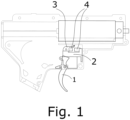
- Fig. 1 , Fig. 2 and Fig. 3 show examples of solutions used in AEG replicas, where the movement of the trigger 1 causes direct pressure on the moving part of the trigger switch 3, and then the sliding moving part causes the contacts 4 in the trigger switch 2 to close and the motor power circuit to close.
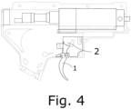
- the trigger moves the same way, with the difference that the pressure is exerted on the microswitch 2. Pressing the trigger 1 activates the solenoid valve which supplies the correct dose of compressed air to the chamber.
- the operation of the trigger in well-known AEG and HPA replicas has several basic disadvantages such as: no possibility to configure the sensitivity of the trigger individually to the user's needs, burning contacts in trigger switches of AEG replicas due to the current flowing in the circuit and the resulting malfunction of the weapon, low resistance of microswitches to mechanical damage and limited number of short-circuit cycles and contacts opening.
- the first invention is a system according to claim 1.
- the second invention is a method according to claim 4.
- the third invention is a system according to claim 8.
- the fourth invention is a method according to claim 11.
- the essence of the solution according to the first invention is based on the fact that the system is equipped with a sensor made of at least one light source D1 and at least one receiver G1 converting a light signal into an electrical signal, wherein the light source D1 and the light receiver Q1 are arranged on the printed circuit board in such a way that they are identically deviated from the vertical axis by the same angle between 0-90°, and their active surfaces are directed towards the trigger of the replica such that the light receiver is illuminated less or more strongly by the light reflected from the moving surface of the trigger.
- the light source D1 is connected to a microcontroller pin.
- the light receiver Q1 is connected to an analog microcontroller pin equipped with an analog-to-digital converter or to an analog-to-digital converter U1 which is coupled with the microcontroller.
- the light source D1 is a light-emitting diode and/or a laser diode.
- the light receiver Q1 is a phototransistor and/or a photodiode and/or a photoresistor and/or a CCD detector.
- the essence of the solution according to the second invention is based on the fact that a light source D1 is controlled in such a manner that at fixed regular time intervals, it emits light for the same period of time.
- the beam of light reflected from the surface of the replica trigger is directed towards a receiver Q1, which converts into an electric current alternately the sum of the reflected light intensity and the intensity of light reaching the receiver Q1 from the surroundings of the replica and the intensity of only the light reaching the receiver Q1 from the surroundings of the replica.
- the electric current flows through a resistor R2, causing a voltage drop at its terminals.
- An analog-to-digital converter converts the voltage of the resistor R2 into a digital form and its value is stored in a buffer storing the last five results.
- the voltage drop data is analyzed in a microcontroller and the difference between samples pr[1] and pr[0], pr[1] and pr[2], pr[3] and pr[2], pr[3] and pr[4] is calculated, wherein the samples pr[0], pr[2] and pr[4] are read when the light source D1 (5) is off and constitute the intensity of only the light coming from the environment of the replica, and pr[1] and pr[3] are read when the light source D1 (5) is on and are the sum of the intensity of light emitted by the light source D1 and then reflected from the surface of the replica trigger and the light intensity coming from the environment of the replica.
- the intensity of only the light emitted by the light source D1 is obtained. If at least one of the four differences between samples pr[1] and pr[0], pr[1] and pr[2], pr[3] and pr[2], and pr[3] and pr[4] is less than a threshold defined previously by the user of the replica in the calibration process, it is treated as a released trigger.
- the calibration process is carried out using applications dedicated to various stationary and mobile devices, and during this process the level of light intensity reaching the receiver Q1 is determined when the trigger is released, pressed, and when the trigger is pressed to the position activating the motor.
- the light source D1 is a light-emitting diode and/or a laser diode.
- the light receiver Q1 is a phototransistor and/or a photodiode and/or a photoresistor and/or a CCD detector.
- the calibration process is carried out using applications dedicated to various stationary and mobile devices, and during this process the level of light intensity reaching the receiver Q1 is determined when the trigger is released, pressed, and when the trigger is pressed to the position activating the motor.
- the essence of the solution according to the third invention is that the system is equipped with a sensor built from two light sources and one receiver Q1 converting a light signal into an electrical signal, wherein the light sources D1 and D2 and the light receiver Q1 are placed on two separate printed circuit boards arranged parallel to each other, between which the trigger of the replica moves. The active surfaces of the light sources D1 and D2 and the light receiver Q1 are directed towards the replica trigger.
- the positions of the light sources D1 and D2 and the light receiver Q1 are strictly defined relative to the position of the replica trigger.
- the edges of the active surfaces of the light source D1 and the light receiver Q1 located closer to the replica trigger are contained in the plane intersecting both printed circuit boards perpendicularly.
- the distance between the light sources D1 and D2, the light receiver Q1 and the trigger is set in such a way that:
- the light sources D1 and D2 are connected to the microcontroller pin.
- the light receiver Q1 is connected to an analog microcontroller pin equipped with an analog-to-digital converter or to an analog-to-digital converter U1 which is coupled with the microcontroller.
- the light sources D1 and D2 are light emitting diodes.
- the light receiver Q1 is a phototransistor and/or a photodiode and/or a photoresistor and/or a CCD detector.
- the essence of the solution according to the fourth invention is that the light sources D1 and D2 are controlled in such a way that, at fixed regular time intervals, they emit light for the same period of time.
- the emitted light goes in the direction of a receiver Q1, which alternately converts into an electric current the sum of the light intensity originating from the light sources D1 and D2 and the intensity of light reaching the receiver Q1 from the environment of the replica, and the intensity of only the light reaching the light receiver Q1 from the environment of the replica.
- the electric current flows through a resistor R2, causing a voltage drop at its terminals.
- An analog-to-digital converter converts the voltage of a resistor R2 into a digital form and its value is stored in a buffer storing the last five results.
- the voltage drop data is analyzed in a microcontroller and using the trigger press recognition algorithm the difference between samples pr[1] and pr[0], pr[1] and pr[2], pr[3] and pr[2], pr[3] and pr[4] is calculated, wherein the samples pr[0], pr[2] and pr[4] are read when the light sources D1 (5) and D2 (9) are off and are the intensity value of the light coming from the environment of the replica, and pr[1] and pr[3] are read when the light sources D1 (5) and D2 (9) are on and are the sum of the light intensity emitted by the light sources D1 and D2 and the intensity of the incoming light from the surroundings of the replica.
- the intensity of only the light emitted by the light sources D1 and D2 is obtained. If at least one of the four differences between samples pr[1] and pr[0], pr[1] and pr[2], pr[3] and pr[2], pr[3] and pr[4] is more than a threshold defined previously by the user of the replica in the calibration process, it is treated as a released trigger. However, if each difference between samples pr[1] and pr [0], pr[1] and pr[2], pr[3] and pr[2], pr[3] and pr[4] is equal to or less than the threshold defined by the user, it is treated as a pressed trigger and this triggers the projectile launch.
- the light sources D1 and D2 are light emitting diodes.
- the light receiver Q1 is a phototransistor and/or a photodiode and/or a photoresistor and/or a CCD detector.
- the calibration process is carried out using applications dedicated to various stationary and mobile devices, and during this process the level of light intensity reaching the receiver Q1 is determined when the trigger is released, pressed, and when the trigger is pressed to the position activating the motor.
- the samples pr[0], pr[2] and pr[4] are read when the light sources D1 (5) and D2 (9) are off and are the intensity value of only the light coming from the environment of the replica and the samples pr[1] and pr[3] are read when the light sources D1 (5) and D2 (9) are on and are the sum of the intensity of light emitted by the light sources D1 and D2 and the intensity of the incoming light from the surroundings of the replica.
- the main advantage of the inventions described above is the fact of using such sensors that are not damaged by normal operation, are trouble-free and maintenance-free.
- the sensors are connected to the input of the analog-to-digital converter, whose processing result is analyzed by the microcontroller, ensuring a precise analysis of the received signal and the precise determination of the position of the replica trigger. Thanks to the miniature dimensions, it is possible to use, according to the need, more than one number of sources and receivers of light, and thus, more precisely control the position of the trigger.
- the algorithm of control and analysis of the signal reaching the sensors makes them resistant to the impact of external lighting, and the electronic photoelements, due to their structure, are resistant to a wide range of temperatures, moisture, vibrations, surges, and electromagnetic interference.
- Users of the replica can adjust and optimize the operation of the replica to meet their needs by calibrating the settings.
- Fig. 5 is a diagram of the interior of the replica
- Fig. 6 is a fragment of this interior at a larger scale
- Fig. 7 is a circuit diagram of a reflective optical sensor in which the microcontroller is equipped with an analog-to-digital converter
- Fig. 8 is a circuit diagram of a reflective optical sensor in which the microcontroller is coupled to an analog-to-digital converter
- Fig. 9 is a graph of the voltage values as a function of time from the last five measurements for a released trigger
- Fig. 10 - a graph of the difference values of the signals visible in Fig. 9
- Fig. 11 - a graph of the value of five consecutive measurements for the pressed trigger
- Fig. 9 is a graph of the voltage values as a function of time from the last five measurements for a released trigger
- Fig. 10 - a graph of the difference values of the signals visible in Fig. 9
- Fig. 11 - a graph of the value of five consecutive measurements for the pressed trigger
- Fig. 13 illustrates how the sensor elements are arranged relative to the trigger (front view)
- Fig. 14 is a view of the sensor elements from above
- Fig. 15 is a view of sensor elements from the front
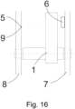
- Fig. 16 is a view of the sensor elements from the left
- Fig. 17 is a circuit diagram of the optical sensor in which the microcontroller is equipped with an analog-to-digital converter
- Fig. 18 is a circuit diagram of an optical sensor in which the microcontroller is coupled to an analog-to-digital converter
- Fig. 13 illustrates how the sensor elements are arranged relative to the trigger (front view)
- Fig. 14 is a view of the sensor elements from above
- Fig. 15 is a view of sensor elements from the front
- Fig. 16 is a view of the sensor elements from the left
- Fig. 17 is a circuit diagram of the optical sensor in which the microcontroller is equipped with an analog-to-digital converter
- Fig. 18 is a circuit diagram of an optical sensor in
- FIG. 19 is a graph of the voltage values as a function of time from the last five measurements for a released trigger, Fig. 20 - a graph of the difference values of the signals visible in Fig. 19 , Fig. 21 - a graph of the value of five consecutive measurements for the pressed trigger, Fig. 22 - a graph of the difference values of the samples r_pr of the signal visible in Fig. 21 .
- the system is equipped with a sensor built from a single light source, which is a light-emitting diode or a laser diode, and one detector converting a light signal into an electrical signal, which is a phototransistor or photodiode or photoresistor or CCD detector, and the light source D1 5 and the light receiver Q1 6 are placed on the printed circuit board 7 in such a way that they are identically inclined from vertical axis by an angle of 27°, and their active surfaces are directed towards the replica trigger 1 such that the light receiver is illuminated less or more strongly by the light reflected from the moving surface of the trigger (1).
- the light source D1 5 is connected to the microcontroller pin.
- the light receiver Q1 6 is connected to an analog microcontroller pin equipped with an analog-to-digital converter as shown in Fig. 8 or to an analog-to-digital converter that is coupled to the microcontroller as shown in Fig. 9 .
- the light source D1 5 is a light-emitting diode or a laser diode.
- the microcontroller controls the light source D1 5 every 500us as follows: for 500us the light source D1 5 shines and for the next 500us the light source D1 5 is off. This cycle is repeated and the light emitted by the light source D1 5 is reflected from the moving part of the trigger 1.
- the receiver Q1 6 is illuminated less or more strongly by the light reflected from the moving surface of the trigger 1.
- the receiver Q1 6 converts the light intensity into an electric current, which flows through the resistor R2, causing a voltage drop at its terminals.
- the analog-to-digital converter converts this voltage into a digital form.
- Samples are taken every 500us. Exactly 100us after taking a sample, the state of the light source D1 5 is changed. Each voltage sample in digital form is stored in a buffer which contains the last five read samples. After each change in the state of the light source D1 5, the microcontroller analyzes the data stored in the buffer.
- Samples: pr [0], pr [2] and pr [4] are read when the light source D1 5 is off and reflect the intensity value of only the ambient light reaching the receiver Q1 6.
- Samples: pr [1] and pr [3] are read when the light source D1 5 is on and reflect the intensity value of the sum of ambient light and the light emitted by the light source D1 5.
- the intensity value of only the light emitted by the light source D1 5 is obtained.
- the light receiver Q1 6 is a phototransistor or photodiode or photoresistor or CCD detector.
- the system is equipped with a sensor built of two light sources D1 5 and D2 9, which are light emitting diodes, and one detector Q1 6 converting the light signal into an electrical signal, which is a phototransistor or photodiode or photoresistor or CCD detector, wherein the light sources D1 5, D2 9 and the light receiver Q1 6 are placed on separate printed circuit boards 7 and 8, between which the replica trigger 1 moves.
- the active surfaces of the light sources D1 5 and D2 9 and the light receiver Q1 6 are directed towards the trigger 1.
- the positions of the light sources D1 5 and D2 9 and the light receiver Q1 6 are strictly defined relative to the position of the replica trigger 1.
- the edges of the active surfaces of the light source D1 5 and the light receiver Q1 6 being closer to the replica trigger 1 are contained in the plane intersecting both printed circuit boards 7 and 8 perpendicularly.
- the moving trigger 1 of the replica creates a shadow on the active surface of the light receiver Q1 6. In the entire range of the trigger 1 movement, the edge of the shadow is formed by the surface of the trigger 1, which is closer to the light sources D1 5 and D2 9.
- the distance between the light sources D1 5 and D2 9, the light receiver Q1 6 and the replica trigger 1 is set in such a way that the replica trigger 1 in the released position forms a shadow originating from the light source D2 9 over a small area of the active surface of the light receiver Q1 6.
- the light source D1 5 illuminates the entire surface of the light receiver Q1 6. In the initial range of the movement of the replica trigger 1, the surface of the shadow originating from the light source D2 9 increases as the trigger 1 is pressed.
- Light source D2 9 is arranged in relation to light source D1 5 so that there is only one position of the replica trigger 1, such that the trigger 1 forms a shadow originating from the light source D2 9 over the entire active surface of the light receiver Q1 6 and light source D1 5 illuminates the entire surface of the light receiver Q1 6.
- the surface of the shadow originating from the light source D1 5 increases on the active surface of the light receiver Q1 6 as the replica trigger 1 is pressed.
- a fully-pressed replica trigger 1 creates a partial shadow originating from the light source D1 5 on the active surface of the light receiver Q1 6. Thanks to this solution, the electrical signal generated by the light receiver Q1 6 changes monotonically throughout the entire range of the replica trigger 1 movement.
- the light sources D1 5 and D2 9 are connected to the microcontroller pin.
- the light receiver Q1 6 is connected to an analog microcontroller pin equipped with an analog-to-digital converter as shown in Fig. 17 or to an analog-to-digital converter that is coupled to the microcontroller as shown in Fig. 18 .
- the light sources D1 5 and D2 9 are light emitting diodes.
- the microcontroller controls light sources D1 5 and D2 9 every 500us as follows: for 500us the light sources D1 5 and D2 9 shine and for the next 500us are off. This cycle is repeated, and the light emitted by the light sources D1 5 and D2 9 is covered by the replica trigger 1.
- the receiver Q1 6 is illuminated less or more strongly by the light emitted by the light sources D1 5 and D2 9.
- the receiver Q1 6 converts the light intensity into an electric current, which flows through the resistor R2, causing a voltage drop at its terminals.
- the analog-to-digital converter converts this voltage into a digital form.
- Samples are taken every 500us. Exactly 100us after taking a sample, the state of the light sources D1 5 and D2 9 is changed. Each voltage sample in digital form is stored in a buffer which contains the last five read samples. After each change in the state of the light source, the microcontroller analyzes the data stored in the buffer.
- Samples: pr[0], pr[2] and pr[4] are read when the light sources D1 5 and D2 9 are off and reflect the intensity value of only the ambient light reaching the light receiver Q1 6.
- Samples: pr[1] and pr[3] are read when the light sources D1 5 and D2 9 are on and reflect the intensity value of the sum of ambient light and the light emitted by the light sources D1 5 and D2 9.
- the intensity value of only the light emitted by the light sources D1 5 and D2 9 is obtained.
- the light receiver Q1 6 is a phototransistor or photodiode or photoresistor or CCD detector.
Landscapes
- Engineering & Computer Science (AREA)
- General Engineering & Computer Science (AREA)
- Physics & Mathematics (AREA)
- General Physics & Mathematics (AREA)
- Length Measuring Devices By Optical Means (AREA)
Priority Applications (2)
| Application Number | Priority Date | Filing Date | Title |
|---|---|---|---|
| US16/382,655 US10782091B2 (en) | 2018-04-13 | 2019-04-12 | System and method of detecting the position of the trigger in gun replicas |
| JP2019076074A JP7351635B2 (ja) | 2018-04-13 | 2019-04-12 | 模擬銃における引き金の位置を検出するシステムおよび方法 |
Applications Claiming Priority (1)
| Application Number | Priority Date | Filing Date | Title |
|---|---|---|---|
| PL425221A PL234505B1 (pl) | 2018-04-13 | 2018-04-13 | Układ i sposób wykrywania pozycji spustu w replikach broni |
Publications (3)
| Publication Number | Publication Date |
|---|---|
| EP3553455A1 EP3553455A1 (en) | 2019-10-16 |
| EP3553455C0 EP3553455C0 (en) | 2024-02-07 |
| EP3553455B1 true EP3553455B1 (en) | 2024-02-07 |
Family
ID=63578835
Family Applications (1)
| Application Number | Title | Priority Date | Filing Date |
|---|---|---|---|
| EP18213227.4A Active EP3553455B1 (en) | 2018-04-13 | 2018-12-17 | System and method of detecting the position of the trigger in gun replicas |
Country Status (4)
| Country | Link |
|---|---|
| US (1) | US10782091B2 (pl) |
| EP (1) | EP3553455B1 (pl) |
| JP (1) | JP7351635B2 (pl) |
| PL (1) | PL234505B1 (pl) |
Families Citing this family (3)
| Publication number | Priority date | Publication date | Assignee | Title |
|---|---|---|---|---|
| US20200041222A1 (en) * | 2018-07-31 | 2020-02-06 | Martin Dieter Lobert | Toggle Trigger |
| EP4043824A1 (en) | 2020-10-23 | 2022-08-17 | GATE Enterprise sp. z o.o. | Trigger for a weapons replica |
| CN220602435U (zh) | 2023-04-24 | 2024-03-15 | 亿舒特科技(深圳)有限公司 | 触发器位置的检测装置及非致命性击发武器 |
Citations (1)
| Publication number | Priority date | Publication date | Assignee | Title |
|---|---|---|---|---|
| US20160054082A1 (en) * | 2012-01-16 | 2016-02-25 | Trackingpoint, Inc. | Trigger Assembly and Method of Optical Detection of a Trigger Assembly State |
Family Cites Families (6)
| Publication number | Priority date | Publication date | Assignee | Title |
|---|---|---|---|---|
| US5727538A (en) * | 1996-04-05 | 1998-03-17 | Shawn Ellis | Electronically actuated marking pellet projector |
| GB2391063B (en) * | 2002-06-01 | 2005-01-12 | Npf Ltd | Paintball marker trigger system |
| US7089697B2 (en) | 2004-01-06 | 2006-08-15 | Planet Eclipse Limited | Trigger transition filter for a paintball marker |
| US7434573B2 (en) | 2004-08-31 | 2008-10-14 | J.T. Sports, Llc | Fiber optic paintball marker |
| US7866307B2 (en) * | 2006-11-03 | 2011-01-11 | Planet Eclipse Limited | Selectable dual trigger mechanism for a paintball marker |
| GB201303741D0 (en) | 2013-03-01 | 2013-04-17 | Artemis Intelligent Power Ltd | Valve unit |
-
2018
- 2018-04-13 PL PL425221A patent/PL234505B1/pl unknown
- 2018-12-17 EP EP18213227.4A patent/EP3553455B1/en active Active
-
2019
- 2019-04-12 US US16/382,655 patent/US10782091B2/en active Active
- 2019-04-12 JP JP2019076074A patent/JP7351635B2/ja active Active
Patent Citations (1)
| Publication number | Priority date | Publication date | Assignee | Title |
|---|---|---|---|---|
| US20160054082A1 (en) * | 2012-01-16 | 2016-02-25 | Trackingpoint, Inc. | Trigger Assembly and Method of Optical Detection of a Trigger Assembly State |
Also Published As
| Publication number | Publication date |
|---|---|
| PL425221A1 (pl) | 2018-09-24 |
| EP3553455A1 (en) | 2019-10-16 |
| EP3553455C0 (en) | 2024-02-07 |
| PL234505B1 (pl) | 2020-03-31 |
| US20190316871A1 (en) | 2019-10-17 |
| JP2019184234A (ja) | 2019-10-24 |
| US10782091B2 (en) | 2020-09-22 |
| JP7351635B2 (ja) | 2023-09-27 |
Similar Documents
| Publication | Publication Date | Title |
|---|---|---|
| US9032656B2 (en) | Trigger assembly and method of optical detection of a trigger assembly state | |
| EP3553455B1 (en) | System and method of detecting the position of the trigger in gun replicas | |
| US3655192A (en) | Light ray projector and target | |
| US8109023B2 (en) | Shot counter | |
| US8100694B2 (en) | Infrared aimpoint detection system | |
| US7076906B2 (en) | Electronic grip-frame for a paintball marker | |
| US20100095574A1 (en) | Trigger activated switch | |
| US5344320A (en) | Dual mode apparatus for assisting in the aiming of a firearm | |
| US20150143731A1 (en) | Trigger Assembly and System Including a Blocking Mechanism | |
| US2934634A (en) | Game and practice attachment for a gun | |
| US20100145669A1 (en) | Firearm shooting simulator | |
| US7661217B2 (en) | Shot counter | |
| US20110261559A1 (en) | Flashlight with Tail Cap and Remote Switch | |
| CN209541535U (zh) | 一种激光模拟训练系统 | |
| ES2657066B1 (es) | Sistema para disparar un arma | |
| ATE221184T1 (de) | Replika-waffe | |
| US11933575B2 (en) | Shooting game system using airsoft gun, method for controlling safe distance, and method for controlling auto-tracer | |
| JP3227466U (ja) | 光の反射を利用する、エアガントリガ検出のシステム | |
| TW201600826A (zh) | 射擊系統、槍及資料處理裝置 | |
| EP2613117A2 (en) | Trigger assembly and system including a blocking mechanism | |
| US3364345A (en) | Light ray projector for marksmanship aim training aid | |
| US20220314110A1 (en) | Opto-Mechanical Human Interface Analog Input Device Based on a Reflective Proximity Processing Method | |
| EP4043824A1 (en) | Trigger for a weapons replica | |
| CN209865262U (zh) | 便于选择功能的电动气弹枪 | |
| DE202020002396U1 (de) | System zur Erkennung der Position vom Abzug in den Waffenrepliken, das das Phänomen der Lichtreflexion verwendet |
Legal Events
| Date | Code | Title | Description |
|---|---|---|---|
| PUAI | Public reference made under article 153(3) epc to a published international application that has entered the european phase |
Free format text: ORIGINAL CODE: 0009012 |
|
| STAA | Information on the status of an ep patent application or granted ep patent |
Free format text: STATUS: THE APPLICATION HAS BEEN PUBLISHED |
|
| AK | Designated contracting states |
Kind code of ref document: A1 Designated state(s): AL AT BE BG CH CY CZ DE DK EE ES FI FR GB GR HR HU IE IS IT LI LT LU LV MC MK MT NL NO PL PT RO RS SE SI SK SM TR |
|
| AX | Request for extension of the european patent |
Extension state: BA ME |
|
| STAA | Information on the status of an ep patent application or granted ep patent |
Free format text: STATUS: REQUEST FOR EXAMINATION WAS MADE |
|
| 17P | Request for examination filed |
Effective date: 20191022 |
|
| RBV | Designated contracting states (corrected) |
Designated state(s): AL AT BE BG CH CY CZ DE DK EE ES FI FR GB GR HR HU IE IS IT LI LT LU LV MC MK MT NL NO PL PT RO RS SE SI SK SM TR |
|
| STAA | Information on the status of an ep patent application or granted ep patent |
Free format text: STATUS: EXAMINATION IS IN PROGRESS |
|
| 17Q | First examination report despatched |
Effective date: 20210617 |
|
| GRAP | Despatch of communication of intention to grant a patent |
Free format text: ORIGINAL CODE: EPIDOSNIGR1 |
|
| STAA | Information on the status of an ep patent application or granted ep patent |
Free format text: STATUS: GRANT OF PATENT IS INTENDED |
|
| INTG | Intention to grant announced |
Effective date: 20220628 |
|
| GRAJ | Information related to disapproval of communication of intention to grant by the applicant or resumption of examination proceedings by the epo deleted |
Free format text: ORIGINAL CODE: EPIDOSDIGR1 |
|
| STAA | Information on the status of an ep patent application or granted ep patent |
Free format text: STATUS: EXAMINATION IS IN PROGRESS |
|
| INTC | Intention to grant announced (deleted) | ||
| GRAP | Despatch of communication of intention to grant a patent |
Free format text: ORIGINAL CODE: EPIDOSNIGR1 |
|
| STAA | Information on the status of an ep patent application or granted ep patent |
Free format text: STATUS: GRANT OF PATENT IS INTENDED |
|
| INTG | Intention to grant announced |
Effective date: 20230425 |
|
| GRAS | Grant fee paid |
Free format text: ORIGINAL CODE: EPIDOSNIGR3 |
|
| RAP3 | Party data changed (applicant data changed or rights of an application transferred) |
Owner name: GATE MENET, WOJTAK SP.J. |
|
| RAP3 | Party data changed (applicant data changed or rights of an application transferred) |
Owner name: GATE ENTERPRISE SP. Z O.O. SP. K. |
|
| GRAA | (expected) grant |
Free format text: ORIGINAL CODE: 0009210 |
|
| STAA | Information on the status of an ep patent application or granted ep patent |
Free format text: STATUS: THE PATENT HAS BEEN GRANTED |
|
| AK | Designated contracting states |
Kind code of ref document: B1 Designated state(s): AL AT BE BG CH CY CZ DE DK EE ES FI FR GB GR HR HU IE IS IT LI LT LU LV MC MK MT NL NO PL PT RO RS SE SI SK SM TR |
|
| REG | Reference to a national code |
Ref country code: GB Ref legal event code: FG4D |
|
| REG | Reference to a national code |
Ref country code: CH Ref legal event code: EP |
|
| REG | Reference to a national code |
Ref country code: IE Ref legal event code: FG4D |
|
| REG | Reference to a national code |
Ref country code: DE Ref legal event code: R096 Ref document number: 602018064910 Country of ref document: DE |
|
| U01 | Request for unitary effect filed |
Effective date: 20240307 |
|
| U07 | Unitary effect registered |
Designated state(s): AT BE BG DE DK EE FI FR IT LT LU LV MT NL PT SE SI Effective date: 20240315 |
|
| PG25 | Lapsed in a contracting state [announced via postgrant information from national office to epo] |
Ref country code: IS Free format text: LAPSE BECAUSE OF FAILURE TO SUBMIT A TRANSLATION OF THE DESCRIPTION OR TO PAY THE FEE WITHIN THE PRESCRIBED TIME-LIMIT Effective date: 20240607 |
|
| PG25 | Lapsed in a contracting state [announced via postgrant information from national office to epo] |
Ref country code: GR Free format text: LAPSE BECAUSE OF FAILURE TO SUBMIT A TRANSLATION OF THE DESCRIPTION OR TO PAY THE FEE WITHIN THE PRESCRIBED TIME-LIMIT Effective date: 20240508 |
|
| PG25 | Lapsed in a contracting state [announced via postgrant information from national office to epo] |
Ref country code: RS Free format text: LAPSE BECAUSE OF FAILURE TO SUBMIT A TRANSLATION OF THE DESCRIPTION OR TO PAY THE FEE WITHIN THE PRESCRIBED TIME-LIMIT Effective date: 20240507 Ref country code: HR Free format text: LAPSE BECAUSE OF FAILURE TO SUBMIT A TRANSLATION OF THE DESCRIPTION OR TO PAY THE FEE WITHIN THE PRESCRIBED TIME-LIMIT Effective date: 20240207 |
|
| PG25 | Lapsed in a contracting state [announced via postgrant information from national office to epo] |
Ref country code: ES Free format text: LAPSE BECAUSE OF FAILURE TO SUBMIT A TRANSLATION OF THE DESCRIPTION OR TO PAY THE FEE WITHIN THE PRESCRIBED TIME-LIMIT Effective date: 20240207 |
|
| PG25 | Lapsed in a contracting state [announced via postgrant information from national office to epo] |
Ref country code: RS Free format text: LAPSE BECAUSE OF FAILURE TO SUBMIT A TRANSLATION OF THE DESCRIPTION OR TO PAY THE FEE WITHIN THE PRESCRIBED TIME-LIMIT Effective date: 20240507 Ref country code: NO Free format text: LAPSE BECAUSE OF FAILURE TO SUBMIT A TRANSLATION OF THE DESCRIPTION OR TO PAY THE FEE WITHIN THE PRESCRIBED TIME-LIMIT Effective date: 20240507 Ref country code: IS Free format text: LAPSE BECAUSE OF FAILURE TO SUBMIT A TRANSLATION OF THE DESCRIPTION OR TO PAY THE FEE WITHIN THE PRESCRIBED TIME-LIMIT Effective date: 20240607 Ref country code: HR Free format text: LAPSE BECAUSE OF FAILURE TO SUBMIT A TRANSLATION OF THE DESCRIPTION OR TO PAY THE FEE WITHIN THE PRESCRIBED TIME-LIMIT Effective date: 20240207 Ref country code: GR Free format text: LAPSE BECAUSE OF FAILURE TO SUBMIT A TRANSLATION OF THE DESCRIPTION OR TO PAY THE FEE WITHIN THE PRESCRIBED TIME-LIMIT Effective date: 20240508 Ref country code: ES Free format text: LAPSE BECAUSE OF FAILURE TO SUBMIT A TRANSLATION OF THE DESCRIPTION OR TO PAY THE FEE WITHIN THE PRESCRIBED TIME-LIMIT Effective date: 20240207 |
|
| PG25 | Lapsed in a contracting state [announced via postgrant information from national office to epo] |
Ref country code: PL Free format text: LAPSE BECAUSE OF FAILURE TO SUBMIT A TRANSLATION OF THE DESCRIPTION OR TO PAY THE FEE WITHIN THE PRESCRIBED TIME-LIMIT Effective date: 20240207 |
|
| PG25 | Lapsed in a contracting state [announced via postgrant information from national office to epo] |
Ref country code: PL Free format text: LAPSE BECAUSE OF FAILURE TO SUBMIT A TRANSLATION OF THE DESCRIPTION OR TO PAY THE FEE WITHIN THE PRESCRIBED TIME-LIMIT Effective date: 20240207 |
|
| PG25 | Lapsed in a contracting state [announced via postgrant information from national office to epo] |
Ref country code: SM Free format text: LAPSE BECAUSE OF FAILURE TO SUBMIT A TRANSLATION OF THE DESCRIPTION OR TO PAY THE FEE WITHIN THE PRESCRIBED TIME-LIMIT Effective date: 20240207 |
|
| PG25 | Lapsed in a contracting state [announced via postgrant information from national office to epo] |
Ref country code: CZ Free format text: LAPSE BECAUSE OF FAILURE TO SUBMIT A TRANSLATION OF THE DESCRIPTION OR TO PAY THE FEE WITHIN THE PRESCRIBED TIME-LIMIT Effective date: 20240207 |
|
| PG25 | Lapsed in a contracting state [announced via postgrant information from national office to epo] |
Ref country code: SK Free format text: LAPSE BECAUSE OF FAILURE TO SUBMIT A TRANSLATION OF THE DESCRIPTION OR TO PAY THE FEE WITHIN THE PRESCRIBED TIME-LIMIT Effective date: 20240207 |
|
| PG25 | Lapsed in a contracting state [announced via postgrant information from national office to epo] |
Ref country code: SM Free format text: LAPSE BECAUSE OF FAILURE TO SUBMIT A TRANSLATION OF THE DESCRIPTION OR TO PAY THE FEE WITHIN THE PRESCRIBED TIME-LIMIT Effective date: 20240207 Ref country code: SK Free format text: LAPSE BECAUSE OF FAILURE TO SUBMIT A TRANSLATION OF THE DESCRIPTION OR TO PAY THE FEE WITHIN THE PRESCRIBED TIME-LIMIT Effective date: 20240207 Ref country code: RO Free format text: LAPSE BECAUSE OF FAILURE TO SUBMIT A TRANSLATION OF THE DESCRIPTION OR TO PAY THE FEE WITHIN THE PRESCRIBED TIME-LIMIT Effective date: 20240207 Ref country code: CZ Free format text: LAPSE BECAUSE OF FAILURE TO SUBMIT A TRANSLATION OF THE DESCRIPTION OR TO PAY THE FEE WITHIN THE PRESCRIBED TIME-LIMIT Effective date: 20240207 |
|
| REG | Reference to a national code |
Ref country code: DE Ref legal event code: R097 Ref document number: 602018064910 Country of ref document: DE |
|
| PLBE | No opposition filed within time limit |
Free format text: ORIGINAL CODE: 0009261 |
|
| STAA | Information on the status of an ep patent application or granted ep patent |
Free format text: STATUS: NO OPPOSITION FILED WITHIN TIME LIMIT |
|
| 26N | No opposition filed |
Effective date: 20241108 |
|
| U21 | Renewal fee for the european patent with unitary effect paid with additional fee |
Year of fee payment: 7 Effective date: 20250523 |
|
| PG25 | Lapsed in a contracting state [announced via postgrant information from national office to epo] |
Ref country code: MC Free format text: LAPSE BECAUSE OF FAILURE TO SUBMIT A TRANSLATION OF THE DESCRIPTION OR TO PAY THE FEE WITHIN THE PRESCRIBED TIME-LIMIT Effective date: 20240207 |
|
| PGFP | Annual fee paid to national office [announced via postgrant information from national office to epo] |
Ref country code: GB Payment date: 20250630 Year of fee payment: 7 |
|
| REG | Reference to a national code |
Ref country code: CH Ref legal event code: PL |
|
| PG25 | Lapsed in a contracting state [announced via postgrant information from national office to epo] |
Ref country code: CH Free format text: LAPSE BECAUSE OF NON-PAYMENT OF DUE FEES Effective date: 20241231 |
|
| PG25 | Lapsed in a contracting state [announced via postgrant information from national office to epo] |
Ref country code: IE Free format text: LAPSE BECAUSE OF NON-PAYMENT OF DUE FEES Effective date: 20241217 |