EP3553421B1 - Thermischer energiespeicher und wärmeabführungssystem - Google Patents
Thermischer energiespeicher und wärmeabführungssystem Download PDFInfo
- Publication number
- EP3553421B1 EP3553421B1 EP19162522.7A EP19162522A EP3553421B1 EP 3553421 B1 EP3553421 B1 EP 3553421B1 EP 19162522 A EP19162522 A EP 19162522A EP 3553421 B1 EP3553421 B1 EP 3553421B1
- Authority
- EP
- European Patent Office
- Prior art keywords
- coolant
- thermal energy
- energy storage
- condenser
- vapor compression
- Prior art date
- Legal status (The legal status is an assumption and is not a legal conclusion. Google has not performed a legal analysis and makes no representation as to the accuracy of the status listed.)
- Active
Links
Images


Classifications
-
- F—MECHANICAL ENGINEERING; LIGHTING; HEATING; WEAPONS; BLASTING
- F25—REFRIGERATION OR COOLING; COMBINED HEATING AND REFRIGERATION SYSTEMS; HEAT PUMP SYSTEMS; MANUFACTURE OR STORAGE OF ICE; LIQUEFACTION SOLIDIFICATION OF GASES
- F25B—REFRIGERATION MACHINES, PLANTS OR SYSTEMS; COMBINED HEATING AND REFRIGERATION SYSTEMS; HEAT PUMP SYSTEMS
- F25B25/00—Machines, plants or systems, using a combination of modes of operation covered by two or more of the groups F25B1/00 - F25B23/00
- F25B25/005—Machines, plants or systems, using a combination of modes of operation covered by two or more of the groups F25B1/00 - F25B23/00 using primary and secondary systems
-
- F—MECHANICAL ENGINEERING; LIGHTING; HEATING; WEAPONS; BLASTING
- F25—REFRIGERATION OR COOLING; COMBINED HEATING AND REFRIGERATION SYSTEMS; HEAT PUMP SYSTEMS; MANUFACTURE OR STORAGE OF ICE; LIQUEFACTION SOLIDIFICATION OF GASES
- F25B—REFRIGERATION MACHINES, PLANTS OR SYSTEMS; COMBINED HEATING AND REFRIGERATION SYSTEMS; HEAT PUMP SYSTEMS
- F25B23/00—Machines, plants or systems, with a single mode of operation not covered by groups F25B1/00 - F25B21/00, e.g. using selective radiation effect
- F25B23/006—Machines, plants or systems, with a single mode of operation not covered by groups F25B1/00 - F25B21/00, e.g. using selective radiation effect boiling cooling systems
-
- F—MECHANICAL ENGINEERING; LIGHTING; HEATING; WEAPONS; BLASTING
- F25—REFRIGERATION OR COOLING; COMBINED HEATING AND REFRIGERATION SYSTEMS; HEAT PUMP SYSTEMS; MANUFACTURE OR STORAGE OF ICE; LIQUEFACTION SOLIDIFICATION OF GASES
- F25B—REFRIGERATION MACHINES, PLANTS OR SYSTEMS; COMBINED HEATING AND REFRIGERATION SYSTEMS; HEAT PUMP SYSTEMS
- F25B31/00—Compressor arrangements
- F25B31/002—Lubrication
- F25B31/004—Lubrication oil recirculating arrangements
-
- F—MECHANICAL ENGINEERING; LIGHTING; HEATING; WEAPONS; BLASTING
- F25—REFRIGERATION OR COOLING; COMBINED HEATING AND REFRIGERATION SYSTEMS; HEAT PUMP SYSTEMS; MANUFACTURE OR STORAGE OF ICE; LIQUEFACTION SOLIDIFICATION OF GASES
- F25B—REFRIGERATION MACHINES, PLANTS OR SYSTEMS; COMBINED HEATING AND REFRIGERATION SYSTEMS; HEAT PUMP SYSTEMS
- F25B40/00—Subcoolers, desuperheaters or superheaters
- F25B40/02—Subcoolers
-
- F—MECHANICAL ENGINEERING; LIGHTING; HEATING; WEAPONS; BLASTING
- F25—REFRIGERATION OR COOLING; COMBINED HEATING AND REFRIGERATION SYSTEMS; HEAT PUMP SYSTEMS; MANUFACTURE OR STORAGE OF ICE; LIQUEFACTION SOLIDIFICATION OF GASES
- F25B—REFRIGERATION MACHINES, PLANTS OR SYSTEMS; COMBINED HEATING AND REFRIGERATION SYSTEMS; HEAT PUMP SYSTEMS
- F25B40/00—Subcoolers, desuperheaters or superheaters
- F25B40/06—Superheaters
-
- F—MECHANICAL ENGINEERING; LIGHTING; HEATING; WEAPONS; BLASTING
- F25—REFRIGERATION OR COOLING; COMBINED HEATING AND REFRIGERATION SYSTEMS; HEAT PUMP SYSTEMS; MANUFACTURE OR STORAGE OF ICE; LIQUEFACTION SOLIDIFICATION OF GASES
- F25B—REFRIGERATION MACHINES, PLANTS OR SYSTEMS; COMBINED HEATING AND REFRIGERATION SYSTEMS; HEAT PUMP SYSTEMS
- F25B7/00—Compression machines, plants or systems, with cascade operation, i.e. with two or more circuits, the heat from the condenser of one circuit being absorbed by the evaporator of the next circuit
-
- F—MECHANICAL ENGINEERING; LIGHTING; HEATING; WEAPONS; BLASTING
- F25—REFRIGERATION OR COOLING; COMBINED HEATING AND REFRIGERATION SYSTEMS; HEAT PUMP SYSTEMS; MANUFACTURE OR STORAGE OF ICE; LIQUEFACTION SOLIDIFICATION OF GASES
- F25B—REFRIGERATION MACHINES, PLANTS OR SYSTEMS; COMBINED HEATING AND REFRIGERATION SYSTEMS; HEAT PUMP SYSTEMS
- F25B2309/00—Gas cycle refrigeration machines
- F25B2309/06—Compression machines, plants or systems characterised by the refrigerant being carbon dioxide
- F25B2309/061—Compression machines, plants or systems characterised by the refrigerant being carbon dioxide with cycle highest pressure above the supercritical pressure
-
- F—MECHANICAL ENGINEERING; LIGHTING; HEATING; WEAPONS; BLASTING
- F25—REFRIGERATION OR COOLING; COMBINED HEATING AND REFRIGERATION SYSTEMS; HEAT PUMP SYSTEMS; MANUFACTURE OR STORAGE OF ICE; LIQUEFACTION SOLIDIFICATION OF GASES
- F25B—REFRIGERATION MACHINES, PLANTS OR SYSTEMS; COMBINED HEATING AND REFRIGERATION SYSTEMS; HEAT PUMP SYSTEMS
- F25B2339/00—Details of evaporators; Details of condensers
- F25B2339/02—Details of evaporators
- F25B2339/024—Evaporators with refrigerant in a vessel in which is situated a heat exchanger
- F25B2339/0242—Evaporators with refrigerant in a vessel in which is situated a heat exchanger having tubular elements
-
- F—MECHANICAL ENGINEERING; LIGHTING; HEATING; WEAPONS; BLASTING
- F25—REFRIGERATION OR COOLING; COMBINED HEATING AND REFRIGERATION SYSTEMS; HEAT PUMP SYSTEMS; MANUFACTURE OR STORAGE OF ICE; LIQUEFACTION SOLIDIFICATION OF GASES
- F25B—REFRIGERATION MACHINES, PLANTS OR SYSTEMS; COMBINED HEATING AND REFRIGERATION SYSTEMS; HEAT PUMP SYSTEMS
- F25B2339/00—Details of evaporators; Details of condensers
- F25B2339/04—Details of condensers
- F25B2339/047—Water-cooled condensers
-
- F—MECHANICAL ENGINEERING; LIGHTING; HEATING; WEAPONS; BLASTING
- F25—REFRIGERATION OR COOLING; COMBINED HEATING AND REFRIGERATION SYSTEMS; HEAT PUMP SYSTEMS; MANUFACTURE OR STORAGE OF ICE; LIQUEFACTION SOLIDIFICATION OF GASES
- F25B—REFRIGERATION MACHINES, PLANTS OR SYSTEMS; COMBINED HEATING AND REFRIGERATION SYSTEMS; HEAT PUMP SYSTEMS
- F25B9/00—Compression machines, plants or systems, in which the refrigerant is air or other gas of low boiling point
- F25B9/002—Compression machines, plants or systems, in which the refrigerant is air or other gas of low boiling point characterised by the refrigerant
- F25B9/008—Compression machines, plants or systems, in which the refrigerant is air or other gas of low boiling point characterised by the refrigerant the refrigerant being carbon dioxide
-
- Y—GENERAL TAGGING OF NEW TECHNOLOGICAL DEVELOPMENTS; GENERAL TAGGING OF CROSS-SECTIONAL TECHNOLOGIES SPANNING OVER SEVERAL SECTIONS OF THE IPC; TECHNICAL SUBJECTS COVERED BY FORMER USPC CROSS-REFERENCE ART COLLECTIONS [XRACs] AND DIGESTS
- Y02—TECHNOLOGIES OR APPLICATIONS FOR MITIGATION OR ADAPTATION AGAINST CLIMATE CHANGE
- Y02E—REDUCTION OF GREENHOUSE GAS [GHG] EMISSIONS, RELATED TO ENERGY GENERATION, TRANSMISSION OR DISTRIBUTION
- Y02E60/00—Enabling technologies; Technologies with a potential or indirect contribution to GHG emissions mitigation
- Y02E60/14—Thermal energy storage
Definitions
- This disclosure relates to cooling systems.
- United States patent application US 2017/153049 A1 discloses an evaporator that comprises: a vessel having a refrigerant inlet for receiving a refrigerant at a lower part of the vessel, and a refrigerant outlet for discharging the refrigerant in an evaporated state at an upper part of the vessel; and a plurality of heat-transfer tubes disposed so as to extend inside the vessel along a longitudinal direction of the vessel, and configured to transfer heat received from a fluid flowing inside the heat-transfer tubes to the refrigerant flowing outside the heat-transfer tubes.
- the plurality of heat-transfer tubes are disposed so that at least one downward flow passage is defined through the plurality of heat-transfer tubes or around the plurality of heat-transfer tubes, the at least one downward flow passage having a width larger than a representative interval between the plurality of heat-transfer tubes.
- a representative interval between the plurality of heat-transfer tubes disposed on an upper side among the plurality of heat-transfer tubes is larger than a representative interval between the plurality of heat-transfer tubes disposed on a lower side among the plurality of heat-transfer tubes.
- United States patent application US 2016/245558 A1 discloses a heat transfer system that includes a first two-phase heat transfer fluid vapor/compression circulation loop that has a compressor, a heat exchanger condenser, an expansion device, and a heat absorption side of a heat exchanger evaporator/condenser.
- a first conduit in a closed fluid circulation loop circulates a first heat transfer fluid therethrough.
- a second two-phase heat transfer fluid circulation loop transfers heat to the first heat transfer fluid circulation loop through the heat exchanger evaporator/condenser, including a heat rejection side of the heat exchanger evaporator/condenser, a liquid pump, a liquid refrigerant reservoir located upstream of the liquid pump and downstream of the heat exchanger evaporator/condenser, and a heat exchanger evaporator.
- a second conduit in a closed fluid circulation loop circulates a second heat transfer fluid therethrough having an ASHRAE Class A toxicity and a Class 1 or 2L flammability rating.
- FIG. 2008/112595 A1 discloses a refrigeration system that has a first refrigeration system and a second refrigeration system that share a common heat exchanger.
- the heat exchanger includes a vessel that operates as a condenser for the second refrigeration system.
- a coil disposed in the vessel operates as an evaporator for the first refrigeration system.
- a method of operating a refrigeration system is also provided that includes exchanging energy between the refrigerant of the first refrigeration system and the refrigerant of the second refrigeration system.
- United States patent US 5561987 discloses a compression refrigeration apparatus for removing heat from a heat load using a falling film evaporator, operated with an azeotropic refrigerant and utilizing a vapor-liquid separator, preferably inside the evaporator vessel.
- a compression refrigeration apparatus for removing heat from a heat load using a falling film evaporator, operated with an azeotropic refrigerant and utilizing a vapor-liquid separator, preferably inside the evaporator vessel.
- two types of heat exchange surfaces are utilized, one for maximizing the axial distribution of refrigerant film on a heat exchange surface, the other for encouraging liquid refrigerant in contact with a heat exchange surface to boil and evaporate.
- the apparatus allows for efficient recovery of lubricant deposited in the evaporator without redistributing the lubricant within the evaporator.
- the present invention provides a cooling system as claimed in claim 1 and a method as claimed in claim 8.
- Optional features are included in the dependent claims.
- the cooling system may comprise a two-phase pump loop comprising a pump, an evaporator configured to evaporate a first coolant supplied by the pump, a condenser configured to condense the first coolant evaporated by the evaporator, and an accumulator configured to deliver the first coolant condensed in the condenser to the pump, a thermal energy storage configured to deliver a liquid portion of a second coolant to the condenser of the two-phase pump loop, wherein the thermal energy storage is configured to separate the second coolant into the liquid portion and a gaseous portion, and a vapor compression system configured to circulate the second coolant, the vapor compression system comprising a compressor and a cooler, wherein the thermal energy storage is configured as a liquid-vapor separator of the vapor compression system, the compressor is configured to compress the gaseous portion of the second coolant from the thermal energy storage, and the cooler is configured to cool the gaseous portion compressed by the compressor.
- the vapor compression system may be a trans-critical vapor compression system.
- the two-phase pump loop may have a heat rejection capacity which is greater than or equal to a cooling capacity of the vapor compression system.
- the condenser of the two-phase pump loop may be positioned within a chamber of the thermal energy storage containing the second coolant.
- the condenser of the two-phase pump loop may be external to the thermal energy storage.
- the cooling system may further comprise a second pump configured to supply the second coolant from the thermal energy storage to the condenser of a two-phase pump loop.
- the thermal energy storage may comprise a container configured to sequester a volume of the liquid portion of the second coolant from the vapor compression system.
- the method may comprise supplying a liquid portion of a second coolant to a condenser from a thermal energy storage, condensing a first coolant within the condenser, wherein the first coolant is in a two-phase pump loop and the first coolant is cooled by the liquid portion of the second coolant passing through the condenser, evaporating a gaseous portion of the second coolant by the condenser, and returning the gaseous portion of the second coolant to the thermal energy storage, wherein the gaseous portion of the second coolant within the thermal energy storage is configured to supply a vapor compression system.
- the method may further comprise selectively operating the vapor compression system when the liquid portion of the second coolant within the thermal energy storage reaches a predetermined temperature.
- the method may further comprise operating the two-phase pump loop and operating the vapor compression system simultaneously to maintain a constant temperature in the thermal energy storage.
- the method may further comprise the second coolant being supplied to the condenser by a pump.
- a cooling system including a two-phase pump loop and a vapor compression system.
- the two-phase pump loop cools a thermal load with a first coolant.
- the vapor compression system is configured to circulate a second coolant.
- the vapor compression system includes a liquid vapor separator which separates the second coolant into a liquid portion and a gaseous portion.
- the liquid vapor separator is a thermal energy storage for the two-phase pump loop.
- a condenser of the two-phase pump loop transfers heat from the first coolant to the liquid portion of the second coolant in the liquid-vapor separator.
- the two-phase pump loop and the thermal energy storage may allow the cooling system to absorb heat from high energy applications to maintain equipment operating within a tight temperature tolerance.
- the thermal energy storage and vapor compression system may allow the cooling system to reject heat generated by the operating equipment to the environment, even in high temperature ambient conditions.
- the combination of the two-phase pump loop, the combined thermal energy storage and vapor compression system may decrease the size and weight of the cooling system compared to systems having a separate, additional thermal energy storage on a third fluid subsystem, allowing the cooling system to be more easily transportable.
- thermal energy storage may allow the cooling system to effectively cool the operating equipment when there is a mismatch between the thermal load and the thermal mass of the two-phase pump loop.
- the operating equipment may create infrequent but large thermal loads which exceed the instant thermal mass of the two-phase pump loop.
- the thermal energy storage may act as a "thermal magazine,” allowing the two-phase pump loop, having a relatively small thermal mass, to quickly absorb the thermal load from the operating equipment and reject the heat to the thermal energy storage which has a relatively greater thermal mass. Such an embodiment may reduce the size of the cooling system.
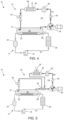
- FIG. 1 illustrates a schematic diagram of a cooling system 10 including a two-phase pump loop 14, a vapor compression system 16, and a thermal energy storage 12.
- the two-phase pump loop 14 may be any system which removes heat from a thermal energy source 78 and rejects thermal energy to the thermal energy storage 12.
- the two-phase pump loop 14 may be filled a first coolant (66 in FIG. 8 ) such as R-134a, R-717, R-744, or water.
- the two-phase pump loop 14 may have a direction of flow D1 from the pump 18 to the evaporator 20, then to the condenser 22, then to the accumulator 24, and then back to the pump 18.
- the two-phase pump loop 14 may include a pump 18, an evaporator 20, a condenser 22, and an accumulator 24.
- the pump 18 may be any component in the two-phase pump loop 14 which supplies the first coolant 66 to the evaporator 20. Examples of the pump 18 may include a rotary pump, a reciprocating pump, or a linear positive displacement pump. The operation of the pump 18 may be controlled according to the cooling needs of the thermal energy source 78.
- the evaporator 20 may be any component which at least partially evaporates the liquid first coolant 66 supplied by the pump. Examples of the evaporator 20 may include a flooded evaporator or a direct expansion evaporator.
- the first coolant 66 passing through the evaporator 20 may cool a thermal load provided by a thermal energy source 78.
- the thermal energy source 78 may be any component which rejects heat to the evaporator 20 in order to be maintained at an operable temperature range. Examples of the thermal energy source 78 may be directed energy systems, electrical computing equipment, or other types of heat-producing machinery.
- the thermal energy source 78 may reject heat to the evaporator 20 through heat sinks submerged in the evaporator 20, or a by a convective heat exchanger.
- the condenser 22 may be any device which receives the coolant evaporated by the evaporator 20. Examples of the condenser 22 may include a shell and tube heat exchanger, a straight tube heat exchanger, or a U-tube heat exchanger.
- the first coolant 66 entering the condenser 22 may be entirely gaseous, or may be a mixture of gas and liquid.
- the first coolant 66 may be entirely liquid, or may be a mixture of gas and liquid having a smaller portion of gas than when entering the condenser 22.
- the accumulator 24 may be any component in which the liquid first coolant 66 may collect and supply first coolant 66 to the pump 18.
- Examples of the accumulator 24 may be a tank, a cylinder, or a tube.
- the accumulator 24 may contain a liquid portion of the first coolant 66 and a gaseous portion of the first coolant 66.
- the liquid portion of the first coolant 66 may be arranged to supply a head pressure to the pump 18 to prevent cavitation of the pump 18.
- the gaseous portion of the first coolant 66 cooled by the condenser 22 may condense in the accumulator 24.
- the two-phase pump loop 14 may also contain a back pressure regulator 26 between the condenser 22 and the evaporator 20.
- the back pressure regulator 26 may be any device which controls the flow of the first coolant 66 from the evaporator 20 to the condenser 22. Examples of the back pressure regulator 26 may include a poppet valve, a check valve, or a pressure-sensing relief valve.
- the back pressure regulator 26 may maintain a constant pressure in the evaporator 20, ensuring adequate cooling of the thermal energy source 78.
- the back pressure regulator 26 may also ensure that the thermal energy source 78 is rejecting heat to the first coolant 66 in the evaporator 20 at a specific constant temperature. This may be a significant feature where the thermal energy source 78 is a high energy or directed-energy system.
- the back pressure regulator 26 may be directly or remotely controlled to accommodate for different cooling needs of the thermal energy source 78 and different operating condition of the pump 18.
- the thermal energy storage 12 may be any component of the cooling system 10 which contains a second coolant and which supplies the second coolant to the condenser 22 of the two-phase pump loop 14 to cool the first coolant 66.
- Examples of the thermal energy storage 12 may include a tank, a drum, or a container.
- the second coolant contained within the thermal energy storage 12 may be any coolant such as R-134a, R-717, R-744, or water.
- the thermal energy storage 12 may operate as a vapor-liquid separator, such as a low pressure receiver, as the second coolant within the thermal energy storage 12 may be contained in both a liquid portion (50 in FIG. 8 ) and a gaseous portion (52 in FIG. 8 ) within a chamber 36 of the thermal energy storage 12.
- Examples of the chamber 36 may include a cavity or a space. As the first coolant 66 passes through the condenser 22, the liquid portion 50 of the second coolant is heated, eventually evaporating and adding to the gaseous portion 52 of the second coolant within the chamber 36 of the thermal energy storage 12.
- the thermal energy storage 12 and two-phase pump loop 14 may be arranged to maintain a temperature of the thermal energy source 78 within a narrow temperature range, for example between about 5-8 degrees Fahrenheit. Keeping the temperature of the thermal energy source 78 within such a narrow temperature range may be important to ensure adequate cooling of the thermal energy source 78. To ensure adequate cooling of the first coolant 66, the liquid portion 50 of the second coolant in the chamber 36 of the thermal energy storage 12 may be maintained at a temperature which is lower than the temperature of the first coolant 66 entering the condenser 22.
- the vapor compression system 16 may be any system which cools the second coolant within the thermal energy storage 12. Examples of the vapor compression system 16 may include a sub-critical vapor compression system or a trans-critical vapor compression system.
- the vapor compression system 16 may include a compressor 28, a cooler 30, and an expansion valve 34.
- the vapor compression system 16 may have a direction of flow D2 from the thermal energy storage 12, to the compressor 28, then to the cooler 30, then to the expansion valve 34, and then back to the thermal energy storage 12.
- multiple vapor compression systems 16 may be fluidly coupled to the thermal energy storage 12. Each of the vapor compression systems 16 may be selectively activated or deactivated according to the cooling needs of the cooling system 10. Alternatively, in some embodiments, the vapor compression system 16 may have multiple compressors 28 and coolers 30 which may be selectively activated or deactivated according to the cooling needs of the thermal energy storage 12.
- the two-phase pump loop 14 may have a heat rejection capacity, the capacity for the two-phase pump loop 14 to absorb heat from the thermal energy source 78, which is greater than a cooling capacity of any of the individual vapor compressions systems 16.
- a total cooling capacity of the multiple vapor compression systems 16 may be greater than or equal to the heat rejection capacity of the two-phase pump loop 14, such that, when the thermal energy storage 12 may be maintained at a thermal equilibrium when the two-phase pump loop 14 and all of the vapor compressions systems 16 are operating.
- multiple two-phase pump loops 14 may be in fluid connection with the thermal energy storage 12, such that the liquid portion 50 of the second coolant cools multiple two-phase pump loops 14.
- a cooling capacity of the vapor compression system 16 may be greater than or equal to a total heat rejection capacity of the multiple two-phase pump loops 14, such that, when the thermal energy storage 12 may be maintained at a thermal equilibrium when all of the two-phase pump loops 14 and the vapor compressions system 16 is operating.
- Other embodiments may include multiple two-phase pump loops 14 and multiple vapor compressions systems 16.
- the compressor 28 may be any component which draws the gaseous portion 52 of the second coolant from the thermal energy storage 12 and supplies the second coolant to the cooler 30 at a higher pressure and a high temperature.
- Examples of the compressor may include a rotary compressor, a reciprocating compressor, a centrifugal compressor, or an axial compressor.
- the cooler 30 may be any container which cools the pressurized gaseous portion 52 of the second coolant supplied by the compressor 28. Examples of the cooler 30 may include a radiator, a serpentine tube, or a container shaped to maximize surface area over volume.
- the pressured gaseous portion 52 of the second coolant may be cooled in the cooler 30 by a gaseous cooling source 32.
- the gaseous cooling source 32 may be any gas which passes over the cooling to absorb heat from the gaseous portion 52 of the second coolant. Examples of the gaseous cooling source 32 may include a fan, a ventilator, or ambient atmospheric conditions.
- the expansion valve 34 may be any component of the vapor compression system 16 which decreases the pressure of the gaseous portion 52 of the second coolant from the cooler 30.
- Examples of the expansion valve 34 may include an internally equalized thermal expansion valve or an externally equalized thermal expansion valve.
- the expansion valve 34 may be fluidly connected to the thermal energy storage 12 to return the cooled second coolant back to the chamber 36 of the thermal energy storage 12. As the pressure drops, the cooled gaseous portion 52 of the second coolant may partially or entirely condense while in the chamber 36 of the thermal energy storage 12.
- the vapor compression system 16 may also include a check valve 40 between the compressor 28 and the cooler 30.
- the check valve 40 may be any component which prevents flow of the second coolant from flowing against the direction of flow D2 of the vapor compression system 16. Examples of the check valve 40 may include a ball check valve, a diaphragm check valve, or a swing check valve. The check valve 40 may be particularly useful to prevent backflow of the second coolant when the compressor 28 is not operating.
- the vapor compression system 16 may also include an oil separator 38 positioned between the compressor 28 and the cooler 30.
- the oil separator 38 may be any component which removes oil from the gaseous portion 52 of the second coolant. Examples of the oil separator 38 may include a cylindrical filter, a conical filter, or filter sheet. The oil removed by the oil separator 38 may be returned to the compressor 28 along a direction of flow D3.
- FIG. 2 is a pressure-enthalpy diagram 200 that illustrates an example of the progression of the pressure and the enthalpy of the second coolant as the second coolant flows through the vapor compression system 16.
- the diagram 200 includes a liquid line 202 and a vapor line 204 for the second coolant used in the vapor compression system 16.
- the second coolant entering the compressor 28 may start as sub-critical superheated vapor.
- the pressure and enthalpy of the second coolant increase.
- the enthalpy of the second coolant decreases.
- the pressure of the second coolant drops below the liquid line 202 and/or the vapor line 204 when expanded (212) at expansion valve 34.
- This liquid portion 50 of the second coolant may return to the thermal energy storage 12.
- the heat of the first coolant 66 within the condenser 22 heats (214) the liquid portion 50 of the second coolant within the thermal energy storage 12 increasing the enthalpy of the second coolant.
- FIG. 3 is a pressure-enthalpy diagram 300 that illustrates an example of the progression of the pressure and the enthalpy of the first coolant 66 as the first coolant 66 flows through the two-phase pump loop 14.
- the diagram 300 includes a liquid line 302 and a vapor line 304 for the second coolant used in the vapor compression system 16.
- the first coolant 66 entering the compressor 28 may start as sub-cooled liquid.
- the first coolant 66 is pressurized (306) by the pump 18, the pressure and enthalpy of the first coolant 66 increase.
- the pressurization (306) of the first coolant 66 may raise the enthalpy and pressure to meet the liquid line 302.
- the enthalpy of the first coolant 66 may increase toward the vapor line 304.
- the evaporator 20 may raise the enthalpy of the first coolant 66 to the vapor line 304, supplying a superheated vapor to the condenser 22.
- the evaporator 20 may raise the enthalpy of the first coolant 66 only partially to the vapor line 304, supplying a gas/liquid mixture to the condenser 22.
- the enthalpy of the first coolant 66 decreases.
- the pressure and enthalpy of the first coolant drop below the liquid line 302 as the first coolant 66 collects as a sub-cooled liquid in the accumulator 24.
- This sub-cooled liquid first coolant 66 may then be pressurized (306) by the pump 18, repeating the cycle.
- FIG. 4 illustrates an alternative embodiment of the cooling system 10 having liquid cooling flow D4 for the cooler 30 in the vapor compression system 16.
- the gaseous portion 52 of the second coolant in the cooler 30 may be cooled by through a flow of liquid D4 across the cooler 30.
- the flow of liquid D4 may be any liquid adequate to cool the second coolant in the cooler 30.
- the flow of liquid D4 may be chilled water or sea water.
- a flow of liquid D4 over the cooler 30 may result in efficient cooling of the second coolant, but maintaining a supply for the flow of liquid D4 may increase the weight of the cooling system 10 and make the cooling system 10 less portable.
- the flow of liquid D4 over the cooler 30 may provide an efficient method of cooling the second coolant in the cooler 30.
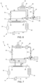
- FIG. 5 illustrates an alternative embodiment of the cooling system 10 incorporating a recuperator 42 into the vapor compression system 16.
- the recuperator 42 may be any component which uses the hot, high pressure second coolant from the cooler 30 to further heat the cool, low pressure gaseous portion 52 of the second coolant before it enters the compressor 28.
- Examples of the recuperator 42 may include a vertical flat panel recuperator, a horizontal flat panel recuperator, or a cellular recuperator.
- the recuperator 42 may be useful for supplementally heating the gaseous portion 52 of the second coolant to remove any remaining liquid elements from the second coolant before entering the compressor 28.
- the recuperator 42 may also be useful for supplementally cooling the second coolant exiting the cooler 30 before reaching the expansion valve 34.
- the flow of the second coolant through the recuperator 42 may increase the efficiency of the vapor compression system 16 if the temperature of the high pressure second coolant exiting the cooler 30 is hotter than the low pressure second coolant exiting the thermal energy storage 12.
- FIG. 6 illustrates an alternative embodiment of the cooling system 10 incorporating a suction accumulator 44 into the vapor compression system 16.
- the suction accumulator 44 may be any component which removes any liquid from the cool, low pressure second coolant entering the compressor 28. Within the suction accumulator 44 hot, high pressure gas may boil any collected liquid in the second coolant headed to the compressor 28 to prevent excessive accumulation.
- a suction accumulator may be beneficial where the operator of the cooling loop is highly transient, such that the thermal energy storage 12 may not sufficiently separate the second coolant into a liquid portion 50 and a gaseous portion 52.
- the suction accumulator 44 may prevent damage to the compressor 28 by minimizing any liquid second coolant from entering the compressor 28.
- FIG. 7 illustrates an alternative embodiment of the cooling system 10 arranged such that the condenser 22 is located outside the thermal energy storage 12.
- Flow of the second coolant D5 between the thermal energy storage 12 and the condenser 22 may be utilized to cool the first coolant 66 in the condenser 22.
- the flow D5 of the liquid portion 50 of the second coolant from the thermal energy storage 12 to the condenser 22 may be gravity fed.
- the liquid portion 50 of the second coolant may descend through a conduit or pipe to the condenser 22.
- the liquid portion 50 of the second coolant may remain in the condenser 22 until evaporating, adding to the gaseous portion 52 of the second coolant upon returning to the thermal energy storage 12.
- FIG. 8 illustrates cross-sectional view of an alternative embodiment of the thermal energy storage 12 having the condenser 22 passing through the chamber 36 of the thermal energy storage 12.
- the liquid portion 50 of the second coolant resting at the bottom of the chamber 36 cools the first coolant 66.
- An outlet 54 of the thermal energy storage 12 allows the gaseous portion 52 to flow D2 to the compressor.
- An inlet 56 of the thermal energy storage 12 allows the second coolant to flow D2 from the expansion valve and add to the liquid portion 50 of the second coolant in the chamber 36.
- the first coolant 66 enters the chamber 36 at inlet 62 of the condenser 22 and exits the chamber 36 at an outlet 64 of the condenser 22.
- the thermal energy storage may have a diameter 58 which is larger than a corresponding diameter 60 of the portion of the condenser 22 carrying the first coolant 66.
- the difference in diameters 58, 60 corresponds to the second coolant within the thermal energy storage 12 having a volume which is greater than the first coolant 66 within the condenser 22.
- the volume of second coolant within the thermal energy storage 12 is between 50 and 150 times greater than the volume of first coolant 66 within the condenser 22.
- the difference in volumes allows the thermal energy storage 12 to cool the first coolant 66 over many cycles of the two-phase pump loop 14 even where the vapor compression system 16 is not operating.
- the vapor compression system 16 may be detached from the thermal energy storage 12 at the inlet 56 and outlet 54 of the thermal energy storage 12. In such embodiments, the thermal energy storage 12 may still be operable even when the vapor compression system 16 is detached. The vapor compression system 16 may be reattached and operated to cool the liquid portion 50 of the second coolant within the thermal energy storage 12.
- FIG. 9 illustrates an alternative embodiment of the cooling system 10 having a second coolant pump 46 arranged to pump the liquid portion 50 of the second coolant from the thermal energy storage 12 through the condenser 22 positioned outside the chamber 36 of the thermal energy storage 12.
- the second coolant pump 46 may be used to allow variable movement of the second coolant through the condenser 22 and back to the thermal energy storage 12.
- the second coolant re-entering the thermal energy storage 12 may be a mixture of gas and liquid.
- the use of the second coolant pump 46 may allow variability along the flow path D5 such that heat transfer from the condenser 22 may be closely controlled. Such a configuration may improve control over pressure and temperature of the first coolant 66 within the two-phase pump loop 14.
- FIG. 10 illustrates an alternative embodiment of the cooling system 10 having additional thermal loads 48 which are cooled by the liquid portion 50 of the second coolant from the thermal energy storage 12.
- the additional thermal loads 48 may be any thermal energy source which requires cooling.
- the additional thermal loads 48 may include housekeeping loads from cooling the pump 18 of the two-phase pump loop 14, cooling an electrical control system for the cooling system 10, cooling the compressor 28, or any other loads associated with thermal energy source 78 that require cooling at a different flow rate than what is provided by the two-phase pump loop 14.
- FIG. 11 illustrates a flow diagram of an example of a method of operating the cooling system 10 (100). The steps may include additional, different, or fewer operations than illustrated in FIG. 11 .
- the method (100) includes supplying the liquid portion 50 of second coolant to the condenser 22 from the thermal energy storage 12 (102).
- the method (100) may also include condensing the first coolant 66 within the condenser 22 (104) and evaporating the gaseous portion 52 of the second coolant by the condenser 22 (106).
- the method (100) may also include returning the gaseous portion 52 of the second coolant to the thermal energy storage 12 (108).
- the method (100) may be implemented with additional, different, or fewer components.
- the vapor compression system 16 may not be continuously operational.
- the method (100) may include operating the vapor compression system 16 when the liquid portion 50 of the second coolant within the chamber 36 of the thermal energy storage 12 reaches a predetermined temperature.
- the two-phase pump loop 14 may not be continuously operational.
- the method (100) of the invention includes operating the vapor compression system 16 when the two-phase pump loop 14 is not being operated.
- the method (100) may also include supplying the second coolant to the condenser 22 by a second coolant pump 46.
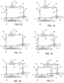
- FIG. 12 illustrates an embodiment of the vapor compression system 16 having the compressor 28 which is mechanically driven, which could also be driven by an electric motor.
- FIG. 13 illustrates an embodiment of the vapor compression system 16 without the check valve 40, which may not be necessary when the vapor compression system 16 is arranged such that liquid second coolant will not flow from the cooler 30 back into the compressor 28.
- FIG. 14 illustrates an embodiment of the vapor compression system 16 without the oil separator 38 which may be used if oil carryover from the compressor 28 is sufficiently low.
- FIG. 15 illustrates an embodiment of the vapor compression system 16 having a back pressure regulator 70 instead of the expansion valve 34.
- FIG. 16 illustrates an embodiment of the vapor compression system 16 having a fixed orifice 72 instead of the expansion valve 34.
- FIG. 17 illustrates an embodiment of the vapor compression system 16 having an oil rectifier 74 positioned between the cooler 30 and the expansion valve 34 to ensure sufficient oil return to the compressor 28.
- FIG. 18 illustrates an embodiment of the two-phase pump loop 14 having a control valve 76 instead of a back pressure regulator 26.
- FIG. 19 illustrates an alternative embodiment of the cooling system having container 80 sequestering a volume 84 of the liquid portion 50 of the second coolant.
- the container 80 may be any object which can hold and sequester the liquid portion 50 of the second coolant, such as a vessel or a subchamber of the chamber 36 of the thermal energy storage 12 divided by a barrier from the rest of the chamber 36.
- the container 80 may be located inside or outside the chamber 36 of the thermal energy storage 12.
- the container 80 may be fluidly coupled to the chamber 36 of the thermal energy storage 12 by an inlet valve 88 and an outlet valve 86.
- the two phase pump loop 14 may operate without the vapor compression system 16. In such situations, the temperature of the second coolant may steadily increase as heat is rejected from the first coolant 66. To restore the cooling capacity of the thermal energy storage 12 and to continue cooling the two-phase pump loop 14, the vapor compression system 16 may be restarted by operating the compressor 28. However, in embodiments where the vapor compression 16 is relatively small compared to the thermal energy storage 12, operating the vapor compression system 16 may cause the temperature of the large quantity of the liquid portion 50 of the second coolant to decline slowly. Instead, a volume 84 of the liquid portion 50 of the second coolant may be sequestered within the container 80 before operating the compressor 28. In such an embodiment, the vapor compression system 16 may initially cool only the unsequestered second coolant in the chamber 36. This would allow the vapor compression system 16 and two-phase pump loop 14 to more quickly cool the unsequestered second coolant to the required operating temperatures.
- the vapor compression system 16 could continue with the cooling of the sequestered second coolant to the operating temperature and then to continue cooling all the second coolant to a temperature necessary to provide sufficient thermal storage capacity.
- the sequestered second coolant may be at a higher temperature than the unsequestered coolant, such that opening of the outlet valve 86 may cause the sequestered coolant to contribute to the gaseous portion 52 of the second coolant in the thermal energy storage 12. Opening of the inlet valve 88 may cause the unsequestered coolant to mix with the sequestered coolant, lowering the temperature of the sequestered volume 84 of the second coolant.
- the container 80 may be insulated.
- the logic illustrated in the flow diagrams may include additional, different, or fewer operations than illustrated.
- the operations illustrated may be performed in an order different than illustrated.
- the phrases "at least one of ⁇ A>, ⁇ B>, ... and ⁇ N>” or “at least one of ⁇ A>, ⁇ B>, ... ⁇ N>, or combinations thereof" or " ⁇ A>, ⁇ B>, ... and/or ⁇ N>” are defined by the Applicant in the broadest sense, superseding any other implied definitions hereinbefore or hereinafter unless expressly asserted by the Applicant to the contrary, to mean one or more elements selected from the group comprising A, B, ... and N.
- the phrases mean any combination of one or more of the elements A, B, ... or N including any one element alone or the one element in combination with one or more of the other elements which may also include, in combination, additional elements not listed.
Landscapes
- Engineering & Computer Science (AREA)
- Physics & Mathematics (AREA)
- Mechanical Engineering (AREA)
- Thermal Sciences (AREA)
- General Engineering & Computer Science (AREA)
- Devices That Are Associated With Refrigeration Equipment (AREA)
- Other Air-Conditioning Systems (AREA)
Claims (11)
- Kühlsystem (10) umfassend:einen Zweiphasen-Pumpenkreislauf (14), der eine Pumpe (18), einen Verdampfer (20), der konfiguriert ist, um ein erstes Kühlmittel (66) zu verdampfen, das durch die Pumpe zugeführt wird, einen Kondensator (22), der konfiguriert ist, um das erste Kühlmittel zu kondensieren, das durch den Verdampfer verdampft wird, und einen Akkumulator (24), der konfiguriert ist, um das erste Kühlmittel, das in dem Kondensator kondensiert ist, an die Pumpe zu liefern, umfasst;einen thermischen Energiespeicher (12), der konfiguriert ist, um einen flüssigen Teil eines zweiten Kühlmittels an den Kondensator des Zweiphasen-Pumpenkreislaufs zu liefern, wobei der thermische Energiespeicher konfiguriert ist, um das zweite Kühlmittel in den flüssigen Teil und einen gasförmigen Teil zu trennen; undein Dampfkompressionssystem (16), das konfiguriert ist, um das zweite Kühlmittel zu zirkulieren, wobei das Dampfkompressionssystem einen Kompressor (28) und einen Kühler (30) umfasst, wobei der thermische Energiespeicher als Flüssigkeits-Dampf-Trenner des Dampfkompressionssystems konfiguriert ist, der Kompressor konfiguriert ist, um den gasförmigen Teil des zweiten Kühlmittels aus dem thermischen Energiespeicher zu komprimieren, und der Kühler konfiguriert ist, um den gasförmigen Teil zu kühlen, der durch den Kompressor komprimiert wird;wobei das Volumen des zweiten Kühlmittels innerhalb des thermischen Energiespeichers (12) zwischen 50 und 150 Mal größer als das Volumen von erstem Kühlmittel (66) innerhalb des Kondensators (22) ist;das Dampfkompressionssystem (16) von dem thermischen Energiespeicher (12) abnehmbar ist; undder thermische Energiespeicher (12) weiter betriebsfähig ist, während das Dampfkompressionssystem abgenommen ist.
- Kühlsystem nach Anspruch 1, wobei das Dampfkompressionssystem (16) ein transkritisches Dampfkompressionssystem ist.
- Kühlsystem nach Anspruch 1 oder 2, wobei der Zweiphasen-Pumpenkreislauf (14) eine Wärmeabführungskapazität aufweist, die größer als eine oder gleich einer Kühlkapazität des Dampfkompressionssystems ist.
- Kühlsystem nach einem vorhergehenden Anspruch, wobei der Kondensator (22) des Zweiphasen-Pumpenkreislaufs innerhalb einer Kammer (36) des thermischen Energiespeichers (12) positioniert ist, die das zweite Kühlmittel enthält.
- Kühlsystem nach einem vorhergehenden Anspruch, wobei der Kondensator (22) des Zweiphasen-Pumpenkreislaufs außerhalb des thermischen Energiespeichers (12) ist.
- Kühlsystem nach einem vorhergehenden Anspruch, ferner umfassend eine zweite Pumpe (46), die konfiguriert ist, um das zweite Kühlmittel von dem thermischen Energiespeichers (12) dem Kondensator (22) des Zweiphasen-Pumpenkreislaufs zuzuführen.
- Kühlsystem nach einem vorhergehenden Anspruch, wobei der thermische Energiespeicher (12) einen Behälter (80) umfasst, der konfiguriert ist, um ein Volumen des flüssigen Teils (50) des zweiten Kühlmittels aus dem Dampfkompressionssystem (16) abzusondern.
- Verfahren, umfassend:Zuführen eines flüssigen Teils (50) eines zweiten Kühlmittels an einen Kondensator (22) aus einem thermischen Energiespeicher (12);Kondensieren eines ersten Kühlmittels (66) innerhalb des Kondensators (22), wobei das erste Kühlmittel in einem Zweiphasen-Pumpenkreislauf (14) ist und das erste Kühlmittel durch den flüssigen Teil (50) des zweiten Kühlmittels gekühlt wird, der durch den Kondensator fließt;Verdampfen eines gasförmigen Teils des zweiten Kühlmittels durch den Kondensator;Zurückführen des gasförmigen Teils des zweiten Kühlmittels zu dem thermischen Energiespeicher (12), wobei der gasförmige Teil des zweiten Kühlmittels innerhalb des thermischen Energiespeichers konfiguriert ist, um einem Dampfkompressionssystem (16) zuzuführen; undBetreiben des Dampfkompressionssystems (16), während der Zweiphasen-Pumpenkreislauf (14) nicht betrieben wird.
- Verfahren nach Anspruch 8, umfassend selektives Betreiben des Dampfkompressionssystems (16), wenn der flüssige Teil (50) des zweiten Kühlmittels innerhalb des thermischen Energiespeichers (12) eine vorbestimmte Temperatur erreicht.
- Verfahren nach Anspruch 8 oder 9, ferner umfassend gleichzeitiges Betreiben des Zweiphasen-Pumpenkreislaufs (14) und Betreiben des Dampfkompressionssystems (16), um eine konstante Temperatur in dem thermischen Energiespeicher (12) aufrechtzuerhalten.
- Verfahren nach einem der Ansprüche 8 bis 10, wobei das zweite Kühlmittel dem Kondensator (22) durch eine Pumpe (46) zugeführt wird.
Applications Claiming Priority (2)
| Application Number | Priority Date | Filing Date | Title |
|---|---|---|---|
| US201862656508P | 2018-04-12 | 2018-04-12 | |
| US16/058,445 US20190316818A1 (en) | 2018-04-12 | 2018-08-08 | Thermal energy storage and heat rejection system |
Publications (3)
| Publication Number | Publication Date |
|---|---|
| EP3553421A2 EP3553421A2 (de) | 2019-10-16 |
| EP3553421A3 EP3553421A3 (de) | 2019-12-25 |
| EP3553421B1 true EP3553421B1 (de) | 2023-11-01 |
Family
ID=65801988
Family Applications (1)
| Application Number | Title | Priority Date | Filing Date |
|---|---|---|---|
| EP19162522.7A Active EP3553421B1 (de) | 2018-04-12 | 2019-03-13 | Thermischer energiespeicher und wärmeabführungssystem |
Country Status (3)
| Country | Link |
|---|---|
| US (2) | US20190316818A1 (de) |
| EP (1) | EP3553421B1 (de) |
| CA (1) | CA3034416A1 (de) |
Families Citing this family (10)
| Publication number | Priority date | Publication date | Assignee | Title |
|---|---|---|---|---|
| CA3082309C (en) * | 2017-11-10 | 2022-07-12 | Hussmann Corporation | Subcritical co2 refrigeration system using thermal storage |
| CN112039219B (zh) * | 2020-09-02 | 2022-02-15 | 广东电网有限责任公司电力调度控制中心 | 一种海上风力发电储能装置 |
| US12135149B2 (en) * | 2020-10-23 | 2024-11-05 | Illuminated Extractors, Ltd. | Heating and refrigeration system |
| CN113550937B (zh) * | 2021-07-14 | 2023-02-07 | 中国科学院力学研究所 | 一种消除泵前汽蚀的装置 |
| TWI809691B (zh) * | 2022-01-27 | 2023-07-21 | 魏均倚 | 異形管致冷及散熱系統 |
| US12460874B2 (en) | 2023-08-03 | 2025-11-04 | United States Of America As Represented By The Secretary Of The Air Force | Two-phase refrigerant pump bladder control system |
| US12529501B2 (en) | 2023-08-09 | 2026-01-20 | Rivian Ip Holdings, Llc | Accumulator for heat pump systems |
| US20250155172A1 (en) * | 2023-11-10 | 2025-05-15 | Hamilton Sundstrand Corporation | Compressor oil recovery in hybrid vcc pumped two phase loops |
| CN120385173A (zh) * | 2024-01-26 | 2025-07-29 | 开利公司 | 换热系统及换热方法 |
| CN119196971A (zh) * | 2024-11-26 | 2024-12-27 | 北京大学南昌创新研究院 | 一种储冰蓄冷冰池及其跨临界和亚临界冷库制冷系统 |
Citations (1)
| Publication number | Priority date | Publication date | Assignee | Title |
|---|---|---|---|---|
| US5561987A (en) * | 1995-05-25 | 1996-10-08 | American Standard Inc. | Falling film evaporator with vapor-liquid separator |
Family Cites Families (20)
| Publication number | Priority date | Publication date | Assignee | Title |
|---|---|---|---|---|
| US4727930A (en) | 1981-08-17 | 1988-03-01 | The Board Of Regents Of The University Of Washington | Heat transfer and storage system |
| US5170639A (en) * | 1991-12-10 | 1992-12-15 | Chander Datta | Cascade refrigeration system |
| US5386709A (en) * | 1992-12-10 | 1995-02-07 | Baltimore Aircoil Company, Inc. | Subcooling and proportional control of subcooling of liquid refrigerant circuits with thermal storage or low temperature reservoirs |
| US5497629A (en) | 1993-03-23 | 1996-03-12 | Store Heat And Produce Energy, Inc. | Heating and cooling systems incorporating thermal storage |
| US6158499A (en) | 1998-12-23 | 2000-12-12 | Fafco, Inc. | Method and apparatus for thermal energy storage |
| US7096679B2 (en) | 2003-12-23 | 2006-08-29 | Tecumseh Products Company | Transcritical vapor compression system and method of operating including refrigerant storage tank and non-variable expansion device |
| US7363772B2 (en) | 2004-08-18 | 2008-04-29 | Ice Energy, Inc. | Thermal energy storage and cooling system with secondary refrigerant isolation |
| US7757508B2 (en) | 2005-08-31 | 2010-07-20 | Ut-Battelle, Llc | Super energy saver heat pump with dynamic hybrid phase change material |
| US20080223074A1 (en) * | 2007-03-09 | 2008-09-18 | Johnson Controls Technology Company | Refrigeration system |
| US8146375B2 (en) * | 2009-03-10 | 2012-04-03 | Thermo King Corporation | Hydrocooler with thermal storage |
| US7905110B2 (en) | 2009-04-02 | 2011-03-15 | Daniel Reich | Thermal energy module |
| CN101893276A (zh) | 2010-04-20 | 2010-11-24 | 上海理工大学 | 由跨临界二氧化碳热泵系统为地板辐射采暖系统供热的系统 |
| US20110083827A1 (en) | 2010-12-15 | 2011-04-14 | Salyer Ival O | Cooling system with integral thermal energy storage |
| US8438864B2 (en) | 2011-03-04 | 2013-05-14 | General Electric Company | Transcritical heat pump water heater and method of operation |
| US9789744B2 (en) | 2011-09-23 | 2017-10-17 | Carrier Corporation | Transport refrigeration system utilizing engine waste heat |
| US10174975B2 (en) * | 2013-10-17 | 2019-01-08 | Carrier Corporation | Two-phase refrigeration system |
| US10047985B2 (en) * | 2014-03-10 | 2018-08-14 | Johnson Controls Technology Company | Subcooling system with thermal energy storage |
| JP6423221B2 (ja) * | 2014-09-25 | 2018-11-14 | 三菱重工サーマルシステムズ株式会社 | 蒸発器及び冷凍機 |
| US20160187014A1 (en) * | 2014-12-29 | 2016-06-30 | Hy-Save Limited | Air Conditioning with Auxiliary Thermal Storage |
| US9695748B2 (en) | 2015-04-10 | 2017-07-04 | Sten Kreuger | Energy storage and retrieval systems |
-
2018
- 2018-08-08 US US16/058,445 patent/US20190316818A1/en not_active Abandoned
-
2019
- 2019-02-19 CA CA3034416A patent/CA3034416A1/en not_active Abandoned
- 2019-03-13 EP EP19162522.7A patent/EP3553421B1/de active Active
-
2022
- 2022-03-18 US US17/698,554 patent/US12359851B2/en active Active
Patent Citations (1)
| Publication number | Priority date | Publication date | Assignee | Title |
|---|---|---|---|---|
| US5561987A (en) * | 1995-05-25 | 1996-10-08 | American Standard Inc. | Falling film evaporator with vapor-liquid separator |
Also Published As
| Publication number | Publication date |
|---|---|
| CA3034416A1 (en) | 2019-10-12 |
| US20190316818A1 (en) | 2019-10-17 |
| US20220205691A1 (en) | 2022-06-30 |
| EP3553421A3 (de) | 2019-12-25 |
| US12359851B2 (en) | 2025-07-15 |
| EP3553421A2 (de) | 2019-10-16 |
Similar Documents
| Publication | Publication Date | Title |
|---|---|---|
| EP3553421B1 (de) | Thermischer energiespeicher und wärmeabführungssystem | |
| US12379139B2 (en) | CO2 refrigeration system with after-cooling | |
| US12203686B2 (en) | Method and apparatus for isothermal cooling | |
| DK167985B1 (da) | Fremgangsmaade ved regulering af et kompressionskoelesystem og varme/koeleanordning til udoevelse af fremgangsmaaden | |
| US9557080B2 (en) | Refrigeration cycle apparatus | |
| EP3204702B1 (de) | Wärmetauscher mit interner flüssigkeitsansaugung | |
| WO2001098719A1 (en) | Subcooling/precooling using ice machine harvest water | |
| US12392530B2 (en) | Chiller system with multiple compressors | |
| KR20060108680A (ko) | 이산화탄소 냉각 시스템용 흡입관 열교환기 | |
| JP2011080736A (ja) | 熱交換装置 | |
| CN217274955U (zh) | 用于能量回收的系统及装置 | |
| JP5971548B2 (ja) | 冷凍装置 | |
| EP3141857B1 (de) | Heizkörper und kältekreislauf mit überkritischem druck | |
| AU2019292493B2 (en) | Apparatus and method for transferring heat | |
| US12146688B2 (en) | Refrigerant vapor compression system with multiple flash tanks | |
| JP2007218466A (ja) | 二次冷媒式冷凍装置 | |
| CN103216964A (zh) | 制冷系统以及用于制冷的方法 |
Legal Events
| Date | Code | Title | Description |
|---|---|---|---|
| PUAI | Public reference made under article 153(3) epc to a published international application that has entered the european phase |
Free format text: ORIGINAL CODE: 0009012 |
|
| STAA | Information on the status of an ep patent application or granted ep patent |
Free format text: STATUS: THE APPLICATION HAS BEEN PUBLISHED |
|
| AK | Designated contracting states |
Kind code of ref document: A2 Designated state(s): AL AT BE BG CH CY CZ DE DK EE ES FI FR GB GR HR HU IE IS IT LI LT LU LV MC MK MT NL NO PL PT RO RS SE SI SK SM TR |
|
| AX | Request for extension of the european patent |
Extension state: BA ME |
|
| PUAL | Search report despatched |
Free format text: ORIGINAL CODE: 0009013 |
|
| AK | Designated contracting states |
Kind code of ref document: A3 Designated state(s): AL AT BE BG CH CY CZ DE DK EE ES FI FR GB GR HR HU IE IS IT LI LT LU LV MC MK MT NL NO PL PT RO RS SE SI SK SM TR |
|
| AX | Request for extension of the european patent |
Extension state: BA ME |
|
| RIC1 | Information provided on ipc code assigned before grant |
Ipc: F25B 40/02 20060101ALI20191120BHEP Ipc: F25B 23/00 20060101ALI20191120BHEP Ipc: F25B 40/06 20060101ALI20191120BHEP Ipc: F25B 25/00 20060101AFI20191120BHEP Ipc: F25B 31/00 20060101ALI20191120BHEP Ipc: F25B 40/00 20060101ALI20191120BHEP |
|
| STAA | Information on the status of an ep patent application or granted ep patent |
Free format text: STATUS: REQUEST FOR EXAMINATION WAS MADE |
|
| 17P | Request for examination filed |
Effective date: 20200622 |
|
| RBV | Designated contracting states (corrected) |
Designated state(s): AL AT BE BG CH CY CZ DE DK EE ES FI FR GB GR HR HU IE IS IT LI LT LU LV MC MK MT NL NO PL PT RO RS SE SI SK SM TR |
|
| STAA | Information on the status of an ep patent application or granted ep patent |
Free format text: STATUS: EXAMINATION IS IN PROGRESS |
|
| 17Q | First examination report despatched |
Effective date: 20220224 |
|
| GRAP | Despatch of communication of intention to grant a patent |
Free format text: ORIGINAL CODE: EPIDOSNIGR1 |
|
| STAA | Information on the status of an ep patent application or granted ep patent |
Free format text: STATUS: GRANT OF PATENT IS INTENDED |
|
| INTG | Intention to grant announced |
Effective date: 20230718 |
|
| GRAS | Grant fee paid |
Free format text: ORIGINAL CODE: EPIDOSNIGR3 |
|
| GRAA | (expected) grant |
Free format text: ORIGINAL CODE: 0009210 |
|
| STAA | Information on the status of an ep patent application or granted ep patent |
Free format text: STATUS: THE PATENT HAS BEEN GRANTED |
|
| P01 | Opt-out of the competence of the unified patent court (upc) registered |
Effective date: 20230912 |
|
| AK | Designated contracting states |
Kind code of ref document: B1 Designated state(s): AL AT BE BG CH CY CZ DE DK EE ES FI FR GB GR HR HU IE IS IT LI LT LU LV MC MK MT NL NO PL PT RO RS SE SI SK SM TR |
|
| REG | Reference to a national code |
Ref country code: GB Ref legal event code: FG4D |
|
| REG | Reference to a national code |
Ref country code: CH Ref legal event code: EP |
|
| REG | Reference to a national code |
Ref country code: IE Ref legal event code: FG4D |
|
| REG | Reference to a national code |
Ref country code: DE Ref legal event code: R096 Ref document number: 602019040403 Country of ref document: DE |
|
| REG | Reference to a national code |
Ref country code: LT Ref legal event code: MG9D |
|
| REG | Reference to a national code |
Ref country code: NL Ref legal event code: MP Effective date: 20231101 |
|
| PG25 | Lapsed in a contracting state [announced via postgrant information from national office to epo] |
Ref country code: GR Free format text: LAPSE BECAUSE OF FAILURE TO SUBMIT A TRANSLATION OF THE DESCRIPTION OR TO PAY THE FEE WITHIN THE PRESCRIBED TIME-LIMIT Effective date: 20240202 |
|
| PG25 | Lapsed in a contracting state [announced via postgrant information from national office to epo] |
Ref country code: IS Free format text: LAPSE BECAUSE OF FAILURE TO SUBMIT A TRANSLATION OF THE DESCRIPTION OR TO PAY THE FEE WITHIN THE PRESCRIBED TIME-LIMIT Effective date: 20240301 |
|
| PG25 | Lapsed in a contracting state [announced via postgrant information from national office to epo] |
Ref country code: LT Free format text: LAPSE BECAUSE OF FAILURE TO SUBMIT A TRANSLATION OF THE DESCRIPTION OR TO PAY THE FEE WITHIN THE PRESCRIBED TIME-LIMIT Effective date: 20231101 |
|
| REG | Reference to a national code |
Ref country code: AT Ref legal event code: MK05 Ref document number: 1627627 Country of ref document: AT Kind code of ref document: T Effective date: 20231101 |
|
| PG25 | Lapsed in a contracting state [announced via postgrant information from national office to epo] |
Ref country code: NL Free format text: LAPSE BECAUSE OF FAILURE TO SUBMIT A TRANSLATION OF THE DESCRIPTION OR TO PAY THE FEE WITHIN THE PRESCRIBED TIME-LIMIT Effective date: 20231101 |
|
| PG25 | Lapsed in a contracting state [announced via postgrant information from national office to epo] |
Ref country code: AT Free format text: LAPSE BECAUSE OF FAILURE TO SUBMIT A TRANSLATION OF THE DESCRIPTION OR TO PAY THE FEE WITHIN THE PRESCRIBED TIME-LIMIT Effective date: 20231101 |
|
| PG25 | Lapsed in a contracting state [announced via postgrant information from national office to epo] |
Ref country code: ES Free format text: LAPSE BECAUSE OF FAILURE TO SUBMIT A TRANSLATION OF THE DESCRIPTION OR TO PAY THE FEE WITHIN THE PRESCRIBED TIME-LIMIT Effective date: 20231101 |
|
| PG25 | Lapsed in a contracting state [announced via postgrant information from national office to epo] |
Ref country code: NL Free format text: LAPSE BECAUSE OF FAILURE TO SUBMIT A TRANSLATION OF THE DESCRIPTION OR TO PAY THE FEE WITHIN THE PRESCRIBED TIME-LIMIT Effective date: 20231101 Ref country code: LT Free format text: LAPSE BECAUSE OF FAILURE TO SUBMIT A TRANSLATION OF THE DESCRIPTION OR TO PAY THE FEE WITHIN THE PRESCRIBED TIME-LIMIT Effective date: 20231101 Ref country code: IS Free format text: LAPSE BECAUSE OF FAILURE TO SUBMIT A TRANSLATION OF THE DESCRIPTION OR TO PAY THE FEE WITHIN THE PRESCRIBED TIME-LIMIT Effective date: 20240301 Ref country code: GR Free format text: LAPSE BECAUSE OF FAILURE TO SUBMIT A TRANSLATION OF THE DESCRIPTION OR TO PAY THE FEE WITHIN THE PRESCRIBED TIME-LIMIT Effective date: 20240202 Ref country code: ES Free format text: LAPSE BECAUSE OF FAILURE TO SUBMIT A TRANSLATION OF THE DESCRIPTION OR TO PAY THE FEE WITHIN THE PRESCRIBED TIME-LIMIT Effective date: 20231101 Ref country code: BG Free format text: LAPSE BECAUSE OF FAILURE TO SUBMIT A TRANSLATION OF THE DESCRIPTION OR TO PAY THE FEE WITHIN THE PRESCRIBED TIME-LIMIT Effective date: 20240201 Ref country code: AT Free format text: LAPSE BECAUSE OF FAILURE TO SUBMIT A TRANSLATION OF THE DESCRIPTION OR TO PAY THE FEE WITHIN THE PRESCRIBED TIME-LIMIT Effective date: 20231101 Ref country code: PT Free format text: LAPSE BECAUSE OF FAILURE TO SUBMIT A TRANSLATION OF THE DESCRIPTION OR TO PAY THE FEE WITHIN THE PRESCRIBED TIME-LIMIT Effective date: 20240301 |
|
| PG25 | Lapsed in a contracting state [announced via postgrant information from national office to epo] |
Ref country code: SE Free format text: LAPSE BECAUSE OF FAILURE TO SUBMIT A TRANSLATION OF THE DESCRIPTION OR TO PAY THE FEE WITHIN THE PRESCRIBED TIME-LIMIT Effective date: 20231101 Ref country code: RS Free format text: LAPSE BECAUSE OF FAILURE TO SUBMIT A TRANSLATION OF THE DESCRIPTION OR TO PAY THE FEE WITHIN THE PRESCRIBED TIME-LIMIT Effective date: 20231101 Ref country code: PL Free format text: LAPSE BECAUSE OF FAILURE TO SUBMIT A TRANSLATION OF THE DESCRIPTION OR TO PAY THE FEE WITHIN THE PRESCRIBED TIME-LIMIT Effective date: 20231101 Ref country code: NO Free format text: LAPSE BECAUSE OF FAILURE TO SUBMIT A TRANSLATION OF THE DESCRIPTION OR TO PAY THE FEE WITHIN THE PRESCRIBED TIME-LIMIT Effective date: 20240201 Ref country code: LV Free format text: LAPSE BECAUSE OF FAILURE TO SUBMIT A TRANSLATION OF THE DESCRIPTION OR TO PAY THE FEE WITHIN THE PRESCRIBED TIME-LIMIT Effective date: 20231101 Ref country code: HR Free format text: LAPSE BECAUSE OF FAILURE TO SUBMIT A TRANSLATION OF THE DESCRIPTION OR TO PAY THE FEE WITHIN THE PRESCRIBED TIME-LIMIT Effective date: 20231101 |
|
| PG25 | Lapsed in a contracting state [announced via postgrant information from national office to epo] |
Ref country code: DK Free format text: LAPSE BECAUSE OF FAILURE TO SUBMIT A TRANSLATION OF THE DESCRIPTION OR TO PAY THE FEE WITHIN THE PRESCRIBED TIME-LIMIT Effective date: 20231101 |
|
| PG25 | Lapsed in a contracting state [announced via postgrant information from national office to epo] |
Ref country code: CZ Free format text: LAPSE BECAUSE OF FAILURE TO SUBMIT A TRANSLATION OF THE DESCRIPTION OR TO PAY THE FEE WITHIN THE PRESCRIBED TIME-LIMIT Effective date: 20231101 |
|
| PG25 | Lapsed in a contracting state [announced via postgrant information from national office to epo] |
Ref country code: SK Free format text: LAPSE BECAUSE OF FAILURE TO SUBMIT A TRANSLATION OF THE DESCRIPTION OR TO PAY THE FEE WITHIN THE PRESCRIBED TIME-LIMIT Effective date: 20231101 |
|
| PG25 | Lapsed in a contracting state [announced via postgrant information from national office to epo] |
Ref country code: SM Free format text: LAPSE BECAUSE OF FAILURE TO SUBMIT A TRANSLATION OF THE DESCRIPTION OR TO PAY THE FEE WITHIN THE PRESCRIBED TIME-LIMIT Effective date: 20231101 Ref country code: SK Free format text: LAPSE BECAUSE OF FAILURE TO SUBMIT A TRANSLATION OF THE DESCRIPTION OR TO PAY THE FEE WITHIN THE PRESCRIBED TIME-LIMIT Effective date: 20231101 Ref country code: IT Free format text: LAPSE BECAUSE OF FAILURE TO SUBMIT A TRANSLATION OF THE DESCRIPTION OR TO PAY THE FEE WITHIN THE PRESCRIBED TIME-LIMIT Effective date: 20231101 Ref country code: EE Free format text: LAPSE BECAUSE OF FAILURE TO SUBMIT A TRANSLATION OF THE DESCRIPTION OR TO PAY THE FEE WITHIN THE PRESCRIBED TIME-LIMIT Effective date: 20231101 Ref country code: DK Free format text: LAPSE BECAUSE OF FAILURE TO SUBMIT A TRANSLATION OF THE DESCRIPTION OR TO PAY THE FEE WITHIN THE PRESCRIBED TIME-LIMIT Effective date: 20231101 Ref country code: CZ Free format text: LAPSE BECAUSE OF FAILURE TO SUBMIT A TRANSLATION OF THE DESCRIPTION OR TO PAY THE FEE WITHIN THE PRESCRIBED TIME-LIMIT Effective date: 20231101 |
|
| REG | Reference to a national code |
Ref country code: DE Ref legal event code: R097 Ref document number: 602019040403 Country of ref document: DE |
|
| PLBE | No opposition filed within time limit |
Free format text: ORIGINAL CODE: 0009261 |
|
| STAA | Information on the status of an ep patent application or granted ep patent |
Free format text: STATUS: NO OPPOSITION FILED WITHIN TIME LIMIT |
|
| 26N | No opposition filed |
Effective date: 20240802 |
|
| PG25 | Lapsed in a contracting state [announced via postgrant information from national office to epo] |
Ref country code: SI Free format text: LAPSE BECAUSE OF FAILURE TO SUBMIT A TRANSLATION OF THE DESCRIPTION OR TO PAY THE FEE WITHIN THE PRESCRIBED TIME-LIMIT Effective date: 20231101 |
|
| PG25 | Lapsed in a contracting state [announced via postgrant information from national office to epo] |
Ref country code: SI Free format text: LAPSE BECAUSE OF FAILURE TO SUBMIT A TRANSLATION OF THE DESCRIPTION OR TO PAY THE FEE WITHIN THE PRESCRIBED TIME-LIMIT Effective date: 20231101 |
|
| REG | Reference to a national code |
Ref country code: CH Ref legal event code: PL |
|
| PG25 | Lapsed in a contracting state [announced via postgrant information from national office to epo] |
Ref country code: LU Free format text: LAPSE BECAUSE OF NON-PAYMENT OF DUE FEES Effective date: 20240313 |
|
| PG25 | Lapsed in a contracting state [announced via postgrant information from national office to epo] |
Ref country code: MC Free format text: LAPSE BECAUSE OF FAILURE TO SUBMIT A TRANSLATION OF THE DESCRIPTION OR TO PAY THE FEE WITHIN THE PRESCRIBED TIME-LIMIT Effective date: 20231101 |
|
| GBPC | Gb: european patent ceased through non-payment of renewal fee |
Effective date: 20240313 |
|
| PG25 | Lapsed in a contracting state [announced via postgrant information from national office to epo] |
Ref country code: MC Free format text: LAPSE BECAUSE OF FAILURE TO SUBMIT A TRANSLATION OF THE DESCRIPTION OR TO PAY THE FEE WITHIN THE PRESCRIBED TIME-LIMIT Effective date: 20231101 Ref country code: LU Free format text: LAPSE BECAUSE OF NON-PAYMENT OF DUE FEES Effective date: 20240313 |
|
| REG | Reference to a national code |
Ref country code: BE Ref legal event code: MM Effective date: 20240331 |
|
| PG25 | Lapsed in a contracting state [announced via postgrant information from national office to epo] |
Ref country code: BE Free format text: LAPSE BECAUSE OF NON-PAYMENT OF DUE FEES Effective date: 20240331 |
|
| PG25 | Lapsed in a contracting state [announced via postgrant information from national office to epo] |
Ref country code: GB Free format text: LAPSE BECAUSE OF NON-PAYMENT OF DUE FEES Effective date: 20240313 |
|
| PG25 | Lapsed in a contracting state [announced via postgrant information from national office to epo] |
Ref country code: FR Free format text: LAPSE BECAUSE OF NON-PAYMENT OF DUE FEES Effective date: 20240331 |
|
| PG25 | Lapsed in a contracting state [announced via postgrant information from national office to epo] |
Ref country code: IE Free format text: LAPSE BECAUSE OF NON-PAYMENT OF DUE FEES Effective date: 20240313 |
|
| PG25 | Lapsed in a contracting state [announced via postgrant information from national office to epo] |
Ref country code: IE Free format text: LAPSE BECAUSE OF NON-PAYMENT OF DUE FEES Effective date: 20240313 Ref country code: GB Free format text: LAPSE BECAUSE OF NON-PAYMENT OF DUE FEES Effective date: 20240313 Ref country code: FR Free format text: LAPSE BECAUSE OF NON-PAYMENT OF DUE FEES Effective date: 20240331 Ref country code: BE Free format text: LAPSE BECAUSE OF NON-PAYMENT OF DUE FEES Effective date: 20240331 Ref country code: CH Free format text: LAPSE BECAUSE OF NON-PAYMENT OF DUE FEES Effective date: 20240331 |
|
| PGFP | Annual fee paid to national office [announced via postgrant information from national office to epo] |
Ref country code: DE Payment date: 20250327 Year of fee payment: 7 |
|
| PG25 | Lapsed in a contracting state [announced via postgrant information from national office to epo] |
Ref country code: RO Free format text: LAPSE BECAUSE OF FAILURE TO SUBMIT A TRANSLATION OF THE DESCRIPTION OR TO PAY THE FEE WITHIN THE PRESCRIBED TIME-LIMIT Effective date: 20231101 |
|
| PG25 | Lapsed in a contracting state [announced via postgrant information from national office to epo] |
Ref country code: CY Free format text: LAPSE BECAUSE OF FAILURE TO SUBMIT A TRANSLATION OF THE DESCRIPTION OR TO PAY THE FEE WITHIN THE PRESCRIBED TIME-LIMIT; INVALID AB INITIO Effective date: 20190313 |
|
| PG25 | Lapsed in a contracting state [announced via postgrant information from national office to epo] |
Ref country code: HU Free format text: LAPSE BECAUSE OF FAILURE TO SUBMIT A TRANSLATION OF THE DESCRIPTION OR TO PAY THE FEE WITHIN THE PRESCRIBED TIME-LIMIT; INVALID AB INITIO Effective date: 20190313 |
|
| PG25 | Lapsed in a contracting state [announced via postgrant information from national office to epo] |
Ref country code: FI Free format text: LAPSE BECAUSE OF FAILURE TO SUBMIT A TRANSLATION OF THE DESCRIPTION OR TO PAY THE FEE WITHIN THE PRESCRIBED TIME-LIMIT Effective date: 20231101 |
|
| PG25 | Lapsed in a contracting state [announced via postgrant information from national office to epo] |
Ref country code: TR Free format text: LAPSE BECAUSE OF FAILURE TO SUBMIT A TRANSLATION OF THE DESCRIPTION OR TO PAY THE FEE WITHIN THE PRESCRIBED TIME-LIMIT Effective date: 20231101 |