EP3553415A1 - Wärmeregulierungssystem - Google Patents
Wärmeregulierungssystem Download PDFInfo
- Publication number
- EP3553415A1 EP3553415A1 EP19169020.5A EP19169020A EP3553415A1 EP 3553415 A1 EP3553415 A1 EP 3553415A1 EP 19169020 A EP19169020 A EP 19169020A EP 3553415 A1 EP3553415 A1 EP 3553415A1
- Authority
- EP
- European Patent Office
- Prior art keywords
- thermal
- multilayer composite
- stack
- layer
- composite stack
- Prior art date
- Legal status (The legal status is an assumption and is not a legal conclusion. Google has not performed a legal analysis and makes no representation as to the accuracy of the status listed.)
- Withdrawn
Links
- 239000002131 composite material Substances 0.000 claims abstract description 142
- 230000005540 biological transmission Effects 0.000 claims abstract description 112
- 239000000463 material Substances 0.000 claims description 33
- 239000010426 asphalt Substances 0.000 claims description 31
- 238000009877 rendering Methods 0.000 claims description 21
- 239000000203 mixture Substances 0.000 claims description 20
- 238000011084 recovery Methods 0.000 claims description 15
- 239000011230 binding agent Substances 0.000 claims description 14
- 238000009499 grossing Methods 0.000 claims description 8
- 229920000642 polymer Polymers 0.000 claims description 6
- 230000006735 deficit Effects 0.000 claims description 4
- 239000002826 coolant Substances 0.000 claims 1
- 230000010354 integration Effects 0.000 abstract description 13
- 239000010410 layer Substances 0.000 description 203
- 239000000835 fiber Substances 0.000 description 25
- 238000000576 coating method Methods 0.000 description 19
- 239000011248 coating agent Substances 0.000 description 17
- 238000009434 installation Methods 0.000 description 13
- 238000010521 absorption reaction Methods 0.000 description 10
- 239000013529 heat transfer fluid Substances 0.000 description 10
- 238000012546 transfer Methods 0.000 description 10
- XLYOFNOQVPJJNP-UHFFFAOYSA-N water Substances O XLYOFNOQVPJJNP-UHFFFAOYSA-N 0.000 description 10
- OKTJSMMVPCPJKN-UHFFFAOYSA-N Carbon Chemical compound [C] OKTJSMMVPCPJKN-UHFFFAOYSA-N 0.000 description 8
- VYPSYNLAJGMNEJ-UHFFFAOYSA-N Silicium dioxide Chemical compound O=[Si]=O VYPSYNLAJGMNEJ-UHFFFAOYSA-N 0.000 description 8
- 230000005855 radiation Effects 0.000 description 7
- 239000004575 stone Substances 0.000 description 7
- 230000004907 flux Effects 0.000 description 6
- 238000009413 insulation Methods 0.000 description 6
- 238000004519 manufacturing process Methods 0.000 description 6
- 239000012528 membrane Substances 0.000 description 6
- 229910052782 aluminium Inorganic materials 0.000 description 5
- XAGFODPZIPBFFR-UHFFFAOYSA-N aluminium Chemical compound [Al] XAGFODPZIPBFFR-UHFFFAOYSA-N 0.000 description 5
- 239000011521 glass Substances 0.000 description 5
- 229910002804 graphite Inorganic materials 0.000 description 5
- 239000010439 graphite Substances 0.000 description 5
- 238000010438 heat treatment Methods 0.000 description 5
- 239000011810 insulating material Substances 0.000 description 5
- 239000002184 metal Substances 0.000 description 5
- 229910052751 metal Inorganic materials 0.000 description 5
- 239000002557 mineral fiber Substances 0.000 description 5
- 239000002344 surface layer Substances 0.000 description 5
- 229920000049 Carbon (fiber) Polymers 0.000 description 4
- 230000002745 absorbent Effects 0.000 description 4
- 239000002250 absorbent Substances 0.000 description 4
- 239000004917 carbon fiber Substances 0.000 description 4
- 210000004027 cell Anatomy 0.000 description 4
- 238000010276 construction Methods 0.000 description 4
- 239000000945 filler Substances 0.000 description 4
- 238000012423 maintenance Methods 0.000 description 4
- 239000000377 silicon dioxide Substances 0.000 description 4
- RYGMFSIKBFXOCR-UHFFFAOYSA-N Copper Chemical compound [Cu] RYGMFSIKBFXOCR-UHFFFAOYSA-N 0.000 description 3
- 238000009792 diffusion process Methods 0.000 description 3
- 238000000605 extraction Methods 0.000 description 3
- 230000003287 optical effect Effects 0.000 description 3
- 239000004417 polycarbonate Substances 0.000 description 3
- 229920000515 polycarbonate Polymers 0.000 description 3
- 230000009467 reduction Effects 0.000 description 3
- 230000008439 repair process Effects 0.000 description 3
- 238000007789 sealing Methods 0.000 description 3
- 239000002893 slag Substances 0.000 description 3
- 229910000831 Steel Inorganic materials 0.000 description 2
- 241001080024 Telles Species 0.000 description 2
- 241001639412 Verres Species 0.000 description 2
- NIXOWILDQLNWCW-UHFFFAOYSA-N acrylic acid group Chemical group C(C=C)(=O)O NIXOWILDQLNWCW-UHFFFAOYSA-N 0.000 description 2
- 230000006978 adaptation Effects 0.000 description 2
- 238000012550 audit Methods 0.000 description 2
- 230000008901 benefit Effects 0.000 description 2
- 239000004566 building material Substances 0.000 description 2
- 230000008859 change Effects 0.000 description 2
- 229910052802 copper Inorganic materials 0.000 description 2
- 239000010949 copper Substances 0.000 description 2
- 230000008021 deposition Effects 0.000 description 2
- 238000010586 diagram Methods 0.000 description 2
- 238000001035 drying Methods 0.000 description 2
- 230000000694 effects Effects 0.000 description 2
- 229940082150 encore Drugs 0.000 description 2
- 238000004146 energy storage Methods 0.000 description 2
- 239000004744 fabric Substances 0.000 description 2
- 239000012530 fluid Substances 0.000 description 2
- 238000007726 management method Methods 0.000 description 2
- 239000012071 phase Substances 0.000 description 2
- 238000010248 power generation Methods 0.000 description 2
- 230000001737 promoting effect Effects 0.000 description 2
- 230000001105 regulatory effect Effects 0.000 description 2
- 239000012779 reinforcing material Substances 0.000 description 2
- 230000002441 reversible effect Effects 0.000 description 2
- 239000002520 smart material Substances 0.000 description 2
- 239000010959 steel Substances 0.000 description 2
- 238000003860 storage Methods 0.000 description 2
- 239000004215 Carbon black (E152) Substances 0.000 description 1
- 101100536354 Drosophila melanogaster tant gene Proteins 0.000 description 1
- 239000004793 Polystyrene Substances 0.000 description 1
- 239000004113 Sepiolite Substances 0.000 description 1
- 239000004411 aluminium Substances 0.000 description 1
- 239000010425 asbestos Substances 0.000 description 1
- 239000011324 bead Substances 0.000 description 1
- 229910052799 carbon Inorganic materials 0.000 description 1
- 230000015556 catabolic process Effects 0.000 description 1
- 239000004568 cement Substances 0.000 description 1
- 238000006243 chemical reaction Methods 0.000 description 1
- 230000000295 complement effect Effects 0.000 description 1
- 239000004567 concrete Substances 0.000 description 1
- 239000004020 conductor Substances 0.000 description 1
- 239000000470 constituent Substances 0.000 description 1
- 239000004035 construction material Substances 0.000 description 1
- 238000001816 cooling Methods 0.000 description 1
- 230000008878 coupling Effects 0.000 description 1
- 238000010168 coupling process Methods 0.000 description 1
- 238000005859 coupling reaction Methods 0.000 description 1
- 230000001186 cumulative effect Effects 0.000 description 1
- 238000006731 degradation reaction Methods 0.000 description 1
- 238000007791 dehumidification Methods 0.000 description 1
- 238000001514 detection method Methods 0.000 description 1
- 238000011161 development Methods 0.000 description 1
- 238000010616 electrical installation Methods 0.000 description 1
- 230000002349 favourable effect Effects 0.000 description 1
- 239000011888 foil Substances 0.000 description 1
- 230000005484 gravity Effects 0.000 description 1
- 239000004519 grease Substances 0.000 description 1
- 238000003306 harvesting Methods 0.000 description 1
- 229930195733 hydrocarbon Natural products 0.000 description 1
- 150000002430 hydrocarbons Chemical class 0.000 description 1
- 230000006872 improvement Effects 0.000 description 1
- 230000001788 irregular Effects 0.000 description 1
- 239000007791 liquid phase Substances 0.000 description 1
- 238000002844 melting Methods 0.000 description 1
- 230000008018 melting Effects 0.000 description 1
- 238000000034 method Methods 0.000 description 1
- 230000004048 modification Effects 0.000 description 1
- 238000012986 modification Methods 0.000 description 1
- 230000003121 nonmonotonic effect Effects 0.000 description 1
- 229920002223 polystyrene Polymers 0.000 description 1
- 229920002635 polyurethane Polymers 0.000 description 1
- 239000004814 polyurethane Substances 0.000 description 1
- 230000002787 reinforcement Effects 0.000 description 1
- 238000012552 review Methods 0.000 description 1
- 229910052895 riebeckite Inorganic materials 0.000 description 1
- 239000011435 rock Substances 0.000 description 1
- 238000005096 rolling process Methods 0.000 description 1
- 230000001932 seasonal effect Effects 0.000 description 1
- 239000004065 semiconductor Substances 0.000 description 1
- 229910052624 sepiolite Inorganic materials 0.000 description 1
- 235000019355 sepiolite Nutrition 0.000 description 1
- 239000002356 single layer Substances 0.000 description 1
- 239000002689 soil Substances 0.000 description 1
- 238000005728 strengthening Methods 0.000 description 1
- 230000009182 swimming Effects 0.000 description 1
- 230000000930 thermomechanical effect Effects 0.000 description 1
- 210000001519 tissue Anatomy 0.000 description 1
- 238000012384 transportation and delivery Methods 0.000 description 1
- 235000013311 vegetables Nutrition 0.000 description 1
- 239000010456 wollastonite Substances 0.000 description 1
- 229910052882 wollastonite Inorganic materials 0.000 description 1
Images

Classifications
-
- F—MECHANICAL ENGINEERING; LIGHTING; HEATING; WEAPONS; BLASTING
- F24—HEATING; RANGES; VENTILATING
- F24S—SOLAR HEAT COLLECTORS; SOLAR HEAT SYSTEMS
- F24S20/00—Solar heat collectors specially adapted for particular uses or environments
- F24S20/60—Solar heat collectors integrated in fixed constructions, e.g. in buildings
- F24S20/64—Solar heat collectors integrated in fixed constructions, e.g. in buildings in the form of floor constructions, grounds or roads
-
- Y—GENERAL TAGGING OF NEW TECHNOLOGICAL DEVELOPMENTS; GENERAL TAGGING OF CROSS-SECTIONAL TECHNOLOGIES SPANNING OVER SEVERAL SECTIONS OF THE IPC; TECHNICAL SUBJECTS COVERED BY FORMER USPC CROSS-REFERENCE ART COLLECTIONS [XRACs] AND DIGESTS
- Y02—TECHNOLOGIES OR APPLICATIONS FOR MITIGATION OR ADAPTATION AGAINST CLIMATE CHANGE
- Y02B—CLIMATE CHANGE MITIGATION TECHNOLOGIES RELATED TO BUILDINGS, e.g. HOUSING, HOUSE APPLIANCES OR RELATED END-USER APPLICATIONS
- Y02B10/00—Integration of renewable energy sources in buildings
- Y02B10/20—Solar thermal
-
- Y—GENERAL TAGGING OF NEW TECHNOLOGICAL DEVELOPMENTS; GENERAL TAGGING OF CROSS-SECTIONAL TECHNOLOGIES SPANNING OVER SEVERAL SECTIONS OF THE IPC; TECHNICAL SUBJECTS COVERED BY FORMER USPC CROSS-REFERENCE ART COLLECTIONS [XRACs] AND DIGESTS
- Y02—TECHNOLOGIES OR APPLICATIONS FOR MITIGATION OR ADAPTATION AGAINST CLIMATE CHANGE
- Y02E—REDUCTION OF GREENHOUSE GAS [GHG] EMISSIONS, RELATED TO ENERGY GENERATION, TRANSMISSION OR DISTRIBUTION
- Y02E10/00—Energy generation through renewable energy sources
- Y02E10/40—Solar thermal energy, e.g. solar towers
Definitions
- the invention relates to the field of integration of solar thermal collectors to a road in order to make it energy-producing, especially thermal.
- Heat recovery by solar gains at a road level may require the installation of solar thermal collectors air or water under the road surface, for example an asphalt pavement.
- solar thermal collectors air or water under the road surface, for example an asphalt pavement.
- Thermo-thermal solar thermal collectors contribute to the extraction of heat stored in the road by mechanical circulation of the heat transfer fluid, for various applications such as the heating of nearby buildings or the supply of domestic hot water.
- the operation of this type of solar thermal collectors is also reversible to help clear snow or de-ice the road, including landing strips, they integrate.
- thermal regulation devices are said to be active because they implement the circulation of a fluid. Their integration requires building or redoing a specific route. Their installation requires expertise that road builders do not have. In particular, the intervention and mobilization of specialized plumbers can generate a significant cost. Furthermore, the use of a circulation of heat transfer fluid in coils of great length poses problems including durability and maintenance. Indeed, the detection and repair of a possible leak is a very strong technical constraint.
- thermoelectric system for urban asphalt road consisting of three paved devices on a roadbed.
- the three devices include a solar heat collection device, a power generation device and an electrical energy storage device.
- the solar heat collection device is used as a heat source for the entire system and is mainly composed of a layer of asphalt doped with thermal conductive materials such as graphite and aluminum foil.
- the power generation device is formed by a plurality of semiconductor thermoelectric sheet modules and silica grease to convert the collected heat into electrical energy.
- the electrical energy storage system includes a DC / DC converter, an inverter and a storage battery.
- thermoelectric system With this thermoelectric system, the damage to the pavement caused by the temperature gradients it undergoes is reduced, the behavior and durability of the road are improved and the urban heat island effect is reduced.
- thermoelectric system requires a strong thermal insulation to avoid losses by thermal conduction out of the system and has a low thermoelectric conversion efficiency. The latter is effectively proportional to the thermal gradient between the hot source and the cold source of the thermoelectric system; but the latter is necessarily weak to avoid the degradation of the hot source that constitutes the road and insofar as the temperature of the cold source is not controlled, but undergone. In addition, such a thermoelectric system does not make the pavement producing heat energy.
- utility model CN 203960710 U a pavement covering comprising: a cushioning layer, a base layer, an intermediate layer and an upper layer successively arranged from bottom to top.
- the intermediate layer comprises a thermal insulation layer, a heat transfer layer in its thickness, a photovoltaic cell panel and a heating cable.
- the thermal insulation layer is located in a lower part of the intermediate layer in contact with the base layer.
- the upper layer comprises a heat generating layer and a transparent layer.
- the transparent layer consists of a high-strength material, high transparency, non-slip and anti-wear.
- the heating layer is made of concrete which has good thermal conductivity, uniform heat radiation and high impact intensity.
- the photovoltaic cell panel is used to convert optical energy into electrical energy.
- a combination of the photovoltaic cell panel with a conventional pavement structure is applicable to melting of ice and snow and can also power the electrical installations equipping the road.
- the thermal and photovoltaic functions it offers are simply cumulative.
- such a coating does not make the heat-generating roadway to other equipment.
- An object of the present invention is therefore to propose a thermal regulation system offering a better level of integration with the road, by limiting or even eliminating the aforementioned disadvantages presented by the solutions of the state of the art. .
- the present invention provides a thermal control system to be arranged together with a road surface to regulate the temperature.
- the system comprises a device for capturing thermal energy, a device for restoring at least part of the energy captured, and a device for transmitting energy connected on the one hand to the recording device and on the other hand the rendering device for transmitting at least a portion of the energy captured to the rendering device, or vice versa.
- At least the capturing device is intended to be at least partly arranged under the road surface and is configured to be in thermal conduction with the road surface.
- the system is such that at least two devices among the capturing device, the transmission device and the rendering device comprise a multilayer composite stack.
- Each multilayer composite stack comprises at least one anisotropic thermal conductive layer and at least one thermally insulating layer.
- at least two corresponding functions among the capture, the transmission and the restitution of the energy are carried out by thermal conduction.
- at least two devices, preferably the three devices, among the capturing device, the transmission device and the restitution device are free of heat transfer fluid circulation pipes.
- the anisotropic thermal conductive layer is directly in contact with the at least one thermally insulating layer.
- the system is such that the rendering device comprises a multilayer composite stack and that at least one of the pickup device and the transmission device comprises a multilayer composite stack different from the composite stack.
- multilayer that includes the rendering device.
- Each multilayer composite stack comprises at least one anisotropic thermal conductive layer and at least one thermally insulating layer.
- at least the capturing device and the transmission device are free of pipes for circulating a heat transfer fluid. In this way, at least two corresponding functions among the capture, the Transmission and restitution of energy are achieved by thermal conduction.
- the capturing device, the transmission device and the restitution device are free of pipes for circulating a heat transfer fluid.
- the anisotropic thermal conductive layer is directly in contact with the at least one thermally insulating layer.
- the restitution device is preferably intended to be at least partly offset relative to the road surface; it does not include more than a portion intended to be arranged under the road surface.
- the restitution device is preferably configured not to be directly in thermal conduction with the road surface.
- At least the capture device and the playback device are not superimposed between them.
- none of the three devices is superimposed, in particular entirely, on any one of the other two devices.
- the proposed integration configuration is a passive solution allowing the management (the extraction but also the routing) by conduction of the heat stored by the road surface, the stored heat being essentially due to the solar gain.
- the system fully integrated, allows to multi-functionalize the road, while synergistically increasing the durability of the road surface through the reduction of temperature gradients to which it is subjected daily and seasonally.
- the system makes it possible to decouple between them the problems of capturing, transmitting and restoring thermal energy.
- the system makes it possible to shift the area of restitution of the energy captured with respect to the zone of capture of the thermal energy, and therefore with respect to the road.
- the multilayer composite stack according to the invention may in fact be advantageously composed of conventional building materials which provide at least some of the functions of the road surface 3, or even the underlayment of the road surface. , and the thermal functions of the system 1.
- the installation of the system 1 according to the invention on roads under construction or repair is relatively simple compared to systems, including so-called active, existing; in particular, it does not require a workforce specialized in other technical fields than those directly and traditionally related to the construction or repair of roads.
- the system as proposed above does not require taking into account sealing constraints to reduce the risk of cracks pipes in which circulates a heat transfer fluid.
- the proposed system is inexpensive in manufacturing, installation and maintenance. Then, if the offer for existing active systems is reduced on the market at the moment, it is hoped, thanks to the system of the invention, a significant increase in supply in the coming years.
- the solar energy harvesting area is not limited, in particular because of its great flexibility of integration and its reduced cost.
- the integration of the system according to the invention does not necessarily induce a modification of the basic composition of the road surface.
- the regulation system according to the invention makes it possible to make the heat-generating roadway for other equipment, such as all types of electronic road equipment, for example billboards or LED lighting, an air recuperator, such as a radiator or a heat pump, a water recuperator, such as pipes or a water tank, a recuperator by the ground, such as a Canadian well or a geothermal power plant.
- equipment such as all types of electronic road equipment, for example billboards or LED lighting
- an air recuperator such as a radiator or a heat pump
- a water recuperator such as pipes or a water tank
- a recuperator by the ground, such as a Canadian well or a geothermal power plant.
- the invention can replace surface layers based on asphalt mix (surface layers and bituminous basecoat) of roads. conventional, while ensuring the functions of these superficial layers.
- the capturing device is configured to constitute at least partly a substructure of the road surface and the restitution device is arranged remotely, for example at a distance of between 1 cm and 10 m, preferably between 10 cm and 2 m, with respect to a side edge of the road surface.
- thermal absorptivity of a material or a composite set of materials means a heat-absorbing capacity of the material or the composite set of materials. Absorptivity is expressed as a dimensionless index taking a value between 0 and 1. This index can be measured as the ratio of the amount of heat absorbed to the amount of heat received by a material or a composite set of materials. A value of zero absorptivity reveals a total inability to absorb heat, while an absorbency value equal to 1 reveals a total capacity for heat absorption. Thus, a material or a composite assembly of materials whose absorbency value is equal to 1 absorbs all the heat reaching it. It should be recognized that no material or composite set of materials actually has an incapacity or a total capacity for heat absorption; all absorb and reflect a non-zero amount of the heat they receive.
- layer or "sub-layer” of a material, a substantially uniform extent of said material. Such an extent fits for example in a plan. It has two main directions of extension and a third direction of extension according to which is taken the thickness of the layer. Here, the thickness is more particularly taken in a direction perpendicular to the principal directions of extension of a layer or an underlayer. On the Figures 1 to 6 , the thickness is taken according to the vertical.
- the term “over”, “overcomes”, “covers” or “underlying” or their equivalents do not necessarily mean “in contact with”.
- the arrangement of a first layer on a second layer does not necessarily mean that the two layers are directly in contact with each other, but that means that the first layer at least partially covers the second layer by being either directly in contact with it or separated from it by at least one other layer or at least one other element.
- the heat recuperator means a technical element to which the heat is intended to be conveyed.
- the heat recovery unit may be at least one of: an air recuperator, such as a radiator or a heat pump, a water recuperator, such as pipes or a water tank, a recuperator by soil, such as a Canadian well or geothermal plant.
- a layer based on a material A means a layer comprising this material A and possibly other materials.
- additional thermal zone means a material zone, distinct from the road surface constituting the main thermal zone, and having a temperature that is substantially constant with respect to the variability of the atmospheric temperature.
- the temperature variations of the additional thermal zone are of smaller amplitude than the variations of atmospheric temperature.
- the additional thermal zone may comprise a superficial portion of the earth's crust.
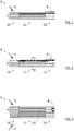
- the thermal control system 1 comprises a thermal energy capture device 10, a device for restoring 12 energy, preferably thermal, and a transmission device 11 of energy, preferably thermal.
- the transmission device 11 is connected on the one hand to the capture device 10, on the other hand to the reproduction device 12; it transmits at least a portion of the thermal energy captured by the capture device 10 to the reproduction device 12.
- the multilayer composite stack 2 comprises at least one anisotropic thermal conductive layer 20 (hereinafter sometimes abbreviated as "CTA layer”) and at least one thermally insulating layer 21.
- CTA layer anisotropic thermal conductive layer 20
- At least two of the capturing device 10, the transmission device 11 and the rendering device 12 are free of heat transfer fluid circulation pipes. Preferably, none of these devices comprises pipes for circulating a heat transfer fluid.
- the thermal control system 1 is preferably purely passive.
- the regulation system 1 is a complex assembly making it possible to provide three basic thermal functions: capture, transfer and dissipate, or even recover, the heat coming from a source of heat external to the system, for example from a solar gain, to restore it preferably to one or more heat recovery 6.
- these three functions are achieved through the adaptation of the absorption properties (ingenious development of an absorptivity gradient) and conduction and thermal insulation properties (ingenious arrangement of a conductivity gradient).
- the absorptivity and conduction gradients will be adapted and variable in the thickness of the complex set, or even in the plane, that constitutes the multilayer composite stack 2 or a juxtaposition of multilayer composite stacks (by at least one their slices).
- These gradients can be created from a judicious choice of materials and number of layers.
- the system fully integrated, allows to replace and multi-functionalize a road or a section of road, conferring in addition to its thermal control functions, a function of energy production, including thermal, to other equipment, or vice versa. This multifunctionality is achieved while synergistically promoting the life of the road or section of road through the reduction of temperature gradients to which the road or section is subjected.
- Thermal transfer interruption at the intermediate levels between the three devices may optionally be implemented to control the operation of the control system, and in particular to be able to interrupt the operation of the control system.
- the transmission device 11 may be connected to at least one of the capture device 10 and the playback device 12 by thermal flow switches configured to successively interrupt and restore the heat flows between the transmission device 11 and at least one of the capture device 10 and the playback device 12, respectively.
- the thermal flux switches may comprise at least one of: a reflector, a device based on a smart material (called “smart materials”), such as a bimetallic sensor for example, and may be arranged together with a manual selector such as a "jumper" type switch. These different means of interruption can be complementary to each other.
- a natural regulation of thermal flows will be done by a predominant thermal gradient between the hot source, here the road surface exposed to solar radiation, and a thermal recuperator and / or between the hot spring and an additional thermal zone (ground , water tank, swimming pool ).
- the additional thermal zone is used for example to dissipate excess heat in summer, when the additional thermal zone is colder than the road surface; the heat is naturally oriented in the direction of the higher thermal gradients.
- the regulation system 1 is therefore naturally reversible.
- the transmission device 11, in particular, can extend so as to be connected to an additional thermal zone to which an excess of thermal energy captured by the capture device 10 can be restored or from which thermal energy can be captured for compensate for a deficit of thermal energy captured by the capture device.
- a prescriptive installation method at the interfaces may also be defined on a case by case basis, in particular as a function of the lateral position of each of these interfaces with respect to the road.
- the CTA layer 20 or the thermally insulating layer 21, or even the two layers, of a first of the three devices may be extended to constitute respectively the CTA layer 20 or the thermally insulating layer 21, or even two layers, of a second of the three devices, the second device being adjacent to the first, to ensure a perfect continuity of thermal functions.
- the invention is however not limited to this example.
- the multilayer composite stack 2 comprises an anisotropic thermal conductive layer 20.
- the latter may comprise a core or a plate or a so-called reinforcing material (fibers, filaments, grids, braids, trellises, fabrics, sheets, etc.) to very high coefficient of conduction and / or thermal absorptivity. It is combined with a thermally insulating layer 21.
- the latter may be based on an insulating material which is preferably adapted to integration with the road, ie which allows the assembly to withstand the stresses to which the road is subjected. according to its use.
- the thermally insulating layer 21 may comprise a material based on a mixture of gravel and road hydraulic binder (LHR), such as bitumen, cast or deposited during the installation of the system 1.
- the chippings constituting part of the layer thermally insulating 21 are preferably chippings of non-refractory and thermal insulating stone, for example a stone low in silica.
- the thermally insulating layer 21 may further comprise insulating fillers such as plant and / or mineral fibers. Mineral fibers are derived from rocks (examples: asbestos, wollastonite, sepiolite) or are synthetic mineral fibers.
- the core, the plate or the reinforcing material of the layer CTA 20 can be directly integrated with the insulating material of the thermally insulating layer 21 or in a part of the thickness of the layer of insulating material of the thermally insulating layer 21. If applicable, a coating 3 of external surface such as asphalt is provided that comes directly or indirectly cover one or the other of the CTA layer 20 and the thermally insulating layer 21.
- the coating 3 is for example based on at least one of: a mixture of asphalt and chippings, a road hydraulic binder such as a bitumen, a black bitumen binder, a transparent bitumen binder, chippings, preferably chippings of non-refractory stone, chippings made of glass, chippings of polymer, in particular of acrylic or polycarbonate type.
- the size of the chippings potentially constituting part of the road surface 3 is not imposed and must be adapted according to the traffic conditions (according to the normative principles of road construction).
- the coating 3 may further comprise thermal absorbent fillers such as carbon fibers, metal fibers, metal slag residues, graphite powder, and the like.
- the composite assembly constituted by the multilayer composite stack 2 is of rigid or flexible structure in the principal extension directions of its layers, adaptable in thickness, in density, in thermal conductivity and in absorptivity, and deployable over large flat surfaces. or curves, continuous or not, preferably smooth, but possibly textured or more simply irregular. More particularly, at least one multilayer composite stack 2 may comprise the coating 3 covering one side of one of the anisotropic thermal conductive layer 20 and the thermally insulating layer 21, this face being directed towards a source of heat outside the system, here basically the sun.
- the principle of the invention consists in particular in exploiting the uptake, by conduction, radiation or convection, by the anisotropic thermal conductive layer 20, of incident sunshine or heat from surrounding thermal energy sources, for its routing and its restitution, preferably by conduction, to at least one thermal recuperator 6.
- the assembly of the layers of the composite can be done on site or previously in the factory for installation on site.
- the CTA layer 20 extends mainly in one plane. It is configured to present, in at least one direction in said plane, a higher thermal conductivity, preferably at least two orders of magnitude, or even at least four orders of magnitude, to its thermal conductivity in a perpendicular direction. audit plan.
- the thermal conductivity of the layer CTA 20 in at least one of its two main directions of extension is greater than 100 W ⁇ m -1 ⁇ K -1 , preferably between 400 W ⁇ m -1 ⁇ K - 1 and 6000 W ⁇ m -1 ⁇ K -1 , and the thermal conductivity of the CTA layer 20 in one direction perpendicular to its two main directions of extension is less than 0.1 W ⁇ m -1 ⁇ K -1 , preferably less than 0.04 W ⁇ m -1 ⁇ K -1 .
- the CTA layer 20 may comprise at least one of a thermal conductive sheet, a thermal conductive grid and a plurality of fibers.
- the thermal conductive sheet or grid is for example made of a material chosen from aluminum, copper, steel and graphite.
- the plurality of fibers comprises at least a plurality of conductive fibers.
- the conductive nature of the conductive fiber can be understood as falling under a thermal and electrical conduction.
- a fiber alone can form a wire, preferably a wire.
- a plurality of fibers form a wire.
- the term "fiber" encompasses both: individual fibers; yarn forming fibers when associated with each other; wires each formed of a single fiber.
- the multilayer composite stack 2 comprises at least two layers, at least the CTA layer 20 and the thermally insulating layer 21, configured together to generate at least one of: a thermal absorbency gradient and a thermal conductivity gradient in the thickness of the stack 2.
- the CTA layer 20 has a thermal absorptivity and a thermal conductivity respectively greater than those of the thermally insulating layer 21.
- the thermal absorptivity and the thermal conductivity vary in the thickness multilayer composite stack 2 in a monotonous manner, as illustrated in FIGS. Figures 1 and 2 , or in a non-monotonic way, and in particular inflected way, as illustrated on the figure 3 .
- Coating 3 may also contribute to the thermal absorbency gradient and / or the thermal conductivity gradient, either by having a thermal absorptivity and / or thermal conductivity as part of the continuity of the thermal absorption gradient and / or thermal conductivity gradient generated by the combination of the CTA layer 20 and the thermally insulating layer 21, either by contributing to increase, or decrease, the amount of heat incident on one and / or the other of the CTA layer 20 and the thermally insulating layer 21.
- the figure 1 illustrates a block diagram of an embodiment of the invention.
- the capture device 10 comprises a multilayer composite stack 2, the layer of which has the greatest thermal absorptivity is directed towards a heat source 5, such as solar radiation.
- the transmission device 11 extends the multilayer composite stack 2 of the capture device 10, over at least a part of its thickness, by a multilayer composite stack 2 which may be either perfectly or partially identical, or completely different from the multilayer composite stack 2 of the capture device 10.
- the next layer or layers in the multilayer composite stack 2 of the capture device 10 have a thermal absorption preferably more in addition reduced.
- the thermal energy captured by the capture device 10 is constrained in that it diffuse only with difficulty in the thickness of the multilayer composite stack 2 of the capture device 10; the heat energy captured will be more diffused by the layer or layers of higher thermal conductivity to the transmission device 11, provided that the thermal gradient between the capture device 10 and the transmission device 11 is favorable, which will be the case in particular if the transmission device is at least partially buried or covered with a thermal insulating material or constitutes at least part of a substructure of a sidewalk.
- the multilayer composite stack 2 of the transmission device 11 comprises a layer having a greater thermal conductivity, this layer being oriented towards the heat source 5. It extends, for example, the layer of greater thermal absorbency of the capture device 10 and can to be of the same nature.
- the following layers in the multilayer composite stack 2 of the transmission device 11 have a thermal conductivity which is preferably smaller and smaller.
- the thermal energy captured by the capture device 10 is transmitted to the transmission device 11 mainly at its layer of higher thermal conductivity.
- the presence of underlying layers of reduced thermal conductivity limits the diffusion of thermal energy in the thickness of the multilayer composite stack 2 of the transmission device 11. Therefore, a large majority of the thermal energy captured by the capture device 10 is transmitted by the transmission device 11 to the reproduction device 12.
- the rendering device 12 also comprises a multilayer composite stack 2, the anisotropic thermal conductive layer 20 of which is arranged so as to be directed towards a heat recuperator 6 outside the system, to which the energy captured and transmitted is to be restored.
- the multilayer composite stack 2 of the rendering device 12 also comprises a thermally insulating layer 21 which covers the layer CTA 20 on a side opposite to the heat recovery unit 6.
- the thermally insulating layer 21 of the rendering device 12 limits the diffusion thermal energy in a direction opposite to the heat recovery unit.
- the figure 3 illustrates a block diagram of another embodiment of the invention.
- the gradient of thermal absorbability and / or thermal conductivity of at least one of the capture device 10 and the transmission device 11 is not monotonous, but inflected.
- the multilayer composite stack 2 constituting at least in part at least one of the capture device 10 and the transmission device 11 then has for example a multilayer configuration substantially symmetrical in its thickness, at least from the point of view of its behavior. thermal. Note also, and we will detail below, that the symmetrical thermal behavior of this embodiment of the system 1 may result in some symmetry of the layers of materials constituting the multilayer composite stack 2.
- the embodiment illustrated on the figure 3 is particularly suitable in the case where a first heat source 5 is on one side of the control system 1 and a second heat source 5 is on the other side of the control system 1.
- the first heat source 5 can be a heat source external to the road to which the regulation system 1 is integrated, while the second heat source 5 can be a source of heat underlying or lateral to the road, by For example, an air duct, a transformer, electric cables, gas pipes or all or part of a geothermal device, these equipment possibly being part of a buried or roadside complex.
- At least one anisotropic thermal conductive layer 20 of the transmission device 11 may extend beyond the transmission device 11 to respectively form at least one anisotropic thermal conductive layer 20 of the reproducing device 12.
- the anisotropic thermal conductive layer 20 of the reproducing device 12 is configured to wind around a pipe in which is intended to circulate a heat transfer fluid, such as water, to form all or part of a heat recovery unit 6.
- the thermally insulating layer 21 of the cooling device restitution 12 at least partially coats the anisotropic thermal conductive layer 20 of the restitution device 12.
- the pipe then forms part of a heat recovery unit 6 to which the thermal energy captured and transmitted is thus restored.
- the multilayer composite stack of the transmission device 11 is symmetrical in its thickness, its two anisotropic thermal conductive layers 20 can be wound on at least a portion of the pipe illustrated on FIG. figure 3 .
- heat recovery units 6 are conceivable; they can take the form of a heat pipe, or even be partly a heat pump or a geothermal power plant. In general, any cold zone may constitute a heat recovery unit 6 for the thermal control system 1 according to the invention.
- the multilayer composite stack 2 of the capture device 10 may have a thermal absorptivity varying from a value of between 0.3 and 1 for at least one layer of the stack oriented towards a heat source 5 outside the system at a value of less than 0.3 for at least one layer of the stack facing away from the heat source 5.
- the multilayer composite stack of the transmission device 11 may have, at least on a first portion 11a extending from the capture device 10, a thermal absorptivity varying from a value of between 0.3 and 1 for at least one layer of the stack directed to a solar gain heat source at a value of less than 0.3 for at least one layer of the stack facing away from the heat source as illustrated in FIG. figure 1 or substantially in the center of the stack as shown on the figure 3 .
- the transmission device 11 is not constituted in the same way over its entire extent. It may thus have different portions 11a, 11b arranged adjacently with each other, preferably between the capturing device 10 and the reproduction device 12. This possibility may imply a break in the continuity of at least one layer constituting the device. transmission 11. Alternatively or in addition, this possibility may involve a change of section of at least one layer of the transmission device 11 between two adjacent portions 11a, 11b of the transmission device 11 or between a portion of the transmission device 11 and one of the capturing device and the rendering device 12 adjacent to said portion.
- the multilayer composite stack 2 of the transmission device 11 may have, at least on a second portion 11b extending from the restitution device 12, a thermal absorption varying from a value of between 0.3 and 1 for at least an intermediate layer 22 of the stack (cf. figure 3 ) to a value of less than 0.3 for at least one of the layers of the stack located on either side of the intermediate layer 22.
- This latter configuration is particularly suitable for an integration of the transmission device 11 under a portion of the pavement or a portion along the road, for example at least under a portion of the sidewalk, which is not exposed to a heat source 5.
- the second portion 11b of the transmission device 11 then has essentially the thermal function of transmission of thermal energy, and negligibly, if not zero, a function of capturing the thermal energy. In the absence of heat energy capture by the transmission device 11, it is preferable that this second portion of the transmission device 11 extends over a limited length preferably less than 10 m.
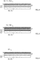
- each multilayer composite coating 2 may be intended to cover a substructure 40 of the road, where appropriate by means of a smoothing underlayer 41 to absorb the irregularities of the underbody 40 and provide a relatively flat deposition surface to the multilayer composite stack 2.
- LHR road hydraulic binder
- the coating 3 may comprise a mix, for example, in the form of a mixture of asphalt or bitumen and chippings.
- the CTA layer 20 may comprise a composite mixture of carbon fibers and tarred membrane, for example an active bitumen membrane, with the appropriate grid and glass sheet reinforcement.
- the thermally insulating layer 21 may be based on at least one insulating material selected from: an asphalt and a polymer.
- the thermally insulating layer 21 may comprise a single layer to ensure its insulation function or two or three thermally insulating layers 21 to enhance the diffusion of heat in the CTA layer 20 by heat reflection effect and contribute to the sealing .
- the figure 5 illustrates a transmission device 11 of the regulating system 1 according to an embodiment of the invention which differs from the transmission device 11 as illustrated on FIG. figure 4 in that it further comprises a thermally insulation 21 disposed preferably directly on the CTA layer 20 and under the coating 3.
- a transmission device 11 provides, from the point of view of the absorptivity and conductivity gradients, a configuration such as that illustrated on the figure 3 .
- the figure 6 illustrates a feedback device 12 of the control system 1 according to an embodiment of the invention which differs from the capture device 10 as shown in FIG. figure 4 in that the places in the stack of the CTA layer 20 and the thermally insulating layer 21 are reversed.
- each coating 3 is illustrated as belonging to each of the multilayer composite stacks 2 illustrated.
- each coating 3 can be considered as contributing to the creation of the absorptivity and conductivity gradients of the multilayer composite stack 2 to which it belongs.
- the invention is however not limited to such an integration of the coating 3 in any multilayer composite stack 2.
- the coatings 3, as illustrated in FIGS. Figures 4 to 6 may be of different natures to each other.
- the coating 3 of the capture device 10 may be a road surface, while the coating 3 of the rendering device may constitute all or part of a sidewalk.
- the capture device 10 as illustrated is configured to constitute at least partly the base of the coating 3 and the rendering device 12 is arranged remotely, for example with a distance of between 1 cm and 10 m, preferably between 10 cm and 2 m, with respect to a lateral edge 31 of the road surface 3.
- the transmission device 11 makes it possible to ensure the transmission of the thermal energy between the capturing device 10 and the rendering device 12.
- the proposed thermal regulation system 1 is a passive solution allowing the management (the extraction but also the routing) by conduction of the heat stored in a roadway.
- the multilayer composite stack 2 is in fact advantageously composed of building materials, which provide the thermal functions of the system 1, and may also be known as road construction materials.
- the system 1 fully integrated, partially replaces and multi-functionalize a road and where appropriate its surroundings while synergistically promoting the life of all the materials constituting the road, including the coating 3 , through the reduction of temperature gradients to which the constituent materials of the road are subjected daily and / or seasonally.
- the system as proposed above does not require taking into account sealing constraints to reduce the risk of cracks pipes in which the heat transfer fluid circulates.
- the proposed system is inexpensive in manufacturing, installation and maintenance. Its manufacture can be done in factory or on site.
- thermal regulator 1 according to the invention, to any type of roadway and any site incorporating a roadway.
- the thermal control system 1 is advantageously independent of the use of fans, especially for the path of heat.
- the thermal production of preheated air or preheated water is dissociated from the capture, transmission and return of thermal energy. It is in fact carried out by coupling the rendering device 12 with a heat recovery unit 6, or even with a heat sink, external to the thermal control system 1.
- the thermal control system 1 according to the invention makes it possible to achieve a limitation of the creep of the road surface (especially when it is made of bitumen), a strengthening of the mechanical connection between the road surface and its base, a limitation of the appearance of potholes and stripping of surrounding materials, and an improvement in the adhesion between the interfaces of the different sub-layers of the roadway, compared to existing thermal regulation systems.
- the thermal regulation system 1 is based on a principle adapted and adjustable according to the seasonal changes. It allows the routing of heat, but also the dissipation of excess heat, by thermal conduction to colder areas (a thermal zone additionally, if applicable) or to a thermal recuperator 6. In warm periods, by higher thermal gradients, the heat captured and transmitted can be either dissipated in the ground as an additional thermal zone, or transferred to thermal applications, particularly for pool heating, preheating sanitary water, an air handling unit, an air dehumidification system, a drying system, etc.
- the thermal capture and thermal transmission functions can be performed in parallel, especially in the case of exposure of the capture device 10 and the transmission device. 11, in particular of the first portion 11a of the transmission device 11, to the heat source 5, including during the delivery of heat.
- the transmission device 11 then only transmitting the heat energy captured by the capture device 10, it may be preferable to limit the distance over which the transmission device 11 must convey the thermal energy. thermal energy to reach the rendering device 12.
- the system can replace all or part of the surface layers.
- bitumen asphalt surface layers and bituminous base layer of conventional roads, while ensuring the functions of these superficial layers.
- the transmission device 11 may be in the form of a plurality of strips of said multilayer composite stack 2. Each strip is then connected by one of its ends to the capture device 10 and by the other of its ends to the device of restitution 12.
- the anisotropic thermal conductive layer 20 may comprise a single aluminum plate, isolated or not.
- the heat source 5 mainly envisaged consists of solar radiation
- other sources of heat are possible, alternatively or in addition.
- each multilayer composite stack 2 may vary according to the needs, and in particular according to the geographical location of the road, its exposure to solar radiation, and its initial composition.
- any one of the multilayer composite coatings may comprise in addition to the CTA layer and the thermally insulating layer, a third layer disposed between the CTA layer and the insulating layer or above the CTA layer.
- the third layer When the third layer is disposed between the layer CTA and the thermally insulating layer, it must have special heat capacity properties, so as not to promote the storage of heat in the road, but on the contrary contribute to its transfer to the device of restitution or the thermal recuperator. Its absorption properties do not come into play here, since it is not exposed directly to the heat source that is the road subjected to solar radiation. For example, it may have low mass and average heat, or average mass and low specific heat.
- the third layer is preferably thinner, or even very thin, with respect to the other two layers so that it can not store a significant amount of thermal energy.
- the third layer therefore preferably has a mass at most equal to that of the thermal insulating layer.
- the third layer When the third layer is disposed above the CTA layer, it may constitute an upper layer of the pavement having advantageous thermal, optical and mechanical properties, for example in terms of drainage. Its thermal and optical properties can correspond to that of the CTA layer with a transmittivity greater than or equal to 0.5.
- a third layer would include transparent bitumen and road glass beads.
- the thermal control system 1 is compatible with local thermal constraints requiring local heat transfer through the capture device 10 and / or the transmission device 11 to protect the more fragile areas of the road local heating of the roadway, for example a locally defined area of the underbody of the road, on which one or the other capturing device 10 and transmission 11 is integrated.
- a portion of the thermally insulating layer 21 may be removed in line with said zone or may be replaced by a less insulating or even thermally conductive layer.
- the heat transfer on either side of the multilayer composite stack 2 is not incompatible with the thermal control system 1 according to the invention, since this transfer remains local.
- Another envisaged variant of the invention could comprise, for the capturing device 10, or even for a part of the transmission device 11, the use of a CTA 20 with a high roughness thanks to the possible adaptation of knots of woven fibers. or a metal grid imitating the granularity (gravel) of the road surface 3.
- the layer CTA 20 is simply covered with LHR loaded with absorbent materials as specified above. Particular attention will be paid to adapting the thickness of the charged LHR layer so that it does not fill or smooth the granulosity of the rough CTA layer.
- the advantage of this variant is that the roughness can be defined from the manufacturing phase in the factory, facilitating and accelerating the installation phase on site.
Landscapes
- Engineering & Computer Science (AREA)
- Physics & Mathematics (AREA)
- Life Sciences & Earth Sciences (AREA)
- Sustainable Development (AREA)
- Sustainable Energy (AREA)
- Thermal Sciences (AREA)
- Chemical & Material Sciences (AREA)
- Combustion & Propulsion (AREA)
- Mechanical Engineering (AREA)
- General Engineering & Computer Science (AREA)
- Road Paving Structures (AREA)
Applications Claiming Priority (1)
| Application Number | Priority Date | Filing Date | Title |
|---|---|---|---|
| FR1853225A FR3080120A1 (fr) | 2018-04-12 | 2018-04-12 | Systeme de regulation thermique |
Publications (1)
| Publication Number | Publication Date |
|---|---|
| EP3553415A1 true EP3553415A1 (de) | 2019-10-16 |
Family
ID=62684916
Family Applications (1)
| Application Number | Title | Priority Date | Filing Date |
|---|---|---|---|
| EP19169020.5A Withdrawn EP3553415A1 (de) | 2018-04-12 | 2019-04-12 | Wärmeregulierungssystem |
Country Status (2)
| Country | Link |
|---|---|
| EP (1) | EP3553415A1 (de) |
| FR (1) | FR3080120A1 (de) |
Cited By (1)
| Publication number | Priority date | Publication date | Assignee | Title |
|---|---|---|---|---|
| CN111851195A (zh) * | 2020-08-21 | 2020-10-30 | 南京林业大学 | 一种热分布均匀的沥青路面结构及各层材料的制备方法 |
Citations (10)
| Publication number | Priority date | Publication date | Assignee | Title |
|---|---|---|---|---|
| WO1999034155A1 (en) * | 1997-12-24 | 1999-07-08 | Wth Vloerverwarming B.V. | Method for installing an energy conversion apparatus in a paving |
| WO2001029320A1 (en) * | 1999-10-19 | 2001-04-26 | Mark Geoffrey Hewitt | Heat storage system |
| CN1884694A (zh) | 2006-06-27 | 2006-12-27 | 武汉理工大学 | 一种导热型沥青路面太阳能集热系统及其应用 |
| KR100896452B1 (ko) * | 2008-11-12 | 2009-05-14 | 신화지티아이 주식회사 | 아스팔트 포장 도로를 집열판으로 이용한 태양열 재생에너지 냉난방장치 |
| US20100154216A1 (en) * | 2008-12-17 | 2010-06-24 | Hulen Michael S | Methods of Modifying Surface Coverings to Embed Conduits Therein |
| US20130014916A1 (en) * | 2010-01-14 | 2013-01-17 | University Of Virginia Patent Foundation | Multifunctional thermal management system and related method |
| CN103633882A (zh) | 2013-11-27 | 2014-03-12 | 朱顺敏 | 一种导热型沥青混凝土路面温差发电系统 |
| CN203960710U (zh) | 2014-05-15 | 2014-11-26 | 中国人民解放军国防科学技术大学 | 人行道太阳能路面 |
| CN106948234A (zh) | 2017-03-29 | 2017-07-14 | 长沙理工大学 | 一种新型调温沥青路面结构 |
| WO2018055314A2 (fr) * | 2016-09-26 | 2018-03-29 | Eurovia | Procede d'indentation d'un echangeur thermique recyclable a haute cadence dans une infrastructure terrestre |
-
2018
- 2018-04-12 FR FR1853225A patent/FR3080120A1/fr not_active Ceased
-
2019
- 2019-04-12 EP EP19169020.5A patent/EP3553415A1/de not_active Withdrawn
Patent Citations (10)
| Publication number | Priority date | Publication date | Assignee | Title |
|---|---|---|---|---|
| WO1999034155A1 (en) * | 1997-12-24 | 1999-07-08 | Wth Vloerverwarming B.V. | Method for installing an energy conversion apparatus in a paving |
| WO2001029320A1 (en) * | 1999-10-19 | 2001-04-26 | Mark Geoffrey Hewitt | Heat storage system |
| CN1884694A (zh) | 2006-06-27 | 2006-12-27 | 武汉理工大学 | 一种导热型沥青路面太阳能集热系统及其应用 |
| KR100896452B1 (ko) * | 2008-11-12 | 2009-05-14 | 신화지티아이 주식회사 | 아스팔트 포장 도로를 집열판으로 이용한 태양열 재생에너지 냉난방장치 |
| US20100154216A1 (en) * | 2008-12-17 | 2010-06-24 | Hulen Michael S | Methods of Modifying Surface Coverings to Embed Conduits Therein |
| US20130014916A1 (en) * | 2010-01-14 | 2013-01-17 | University Of Virginia Patent Foundation | Multifunctional thermal management system and related method |
| CN103633882A (zh) | 2013-11-27 | 2014-03-12 | 朱顺敏 | 一种导热型沥青混凝土路面温差发电系统 |
| CN203960710U (zh) | 2014-05-15 | 2014-11-26 | 中国人民解放军国防科学技术大学 | 人行道太阳能路面 |
| WO2018055314A2 (fr) * | 2016-09-26 | 2018-03-29 | Eurovia | Procede d'indentation d'un echangeur thermique recyclable a haute cadence dans une infrastructure terrestre |
| CN106948234A (zh) | 2017-03-29 | 2017-07-14 | 长沙理工大学 | 一种新型调温沥青路面结构 |
Non-Patent Citations (1)
| Title |
|---|
| DATABASE WPI Section PQ Week 200941, Derwent World Patents Index; Class Q74, AN 2009-K38229, XP002786707 * |
Cited By (1)
| Publication number | Priority date | Publication date | Assignee | Title |
|---|---|---|---|---|
| CN111851195A (zh) * | 2020-08-21 | 2020-10-30 | 南京林业大学 | 一种热分布均匀的沥青路面结构及各层材料的制备方法 |
Also Published As
| Publication number | Publication date |
|---|---|
| FR3080120A1 (fr) | 2019-10-18 |
Similar Documents
| Publication | Publication Date | Title |
|---|---|---|
| US8443794B2 (en) | Systems and methods for operating environmental equipment utilizing energy obtained from manufactured surface coverings | |
| WO2020174177A1 (fr) | Dispositif fonctionnel integrable dans une chaussée circulable et procédé de fabrication d'une chaussée circulable avec un tel dispositif fonctionnel | |
| Andriopoulou | A review on energy harvesting from roads. | |
| EP3553415A1 (de) | Wärmeregulierungssystem | |
| FR2939162A1 (fr) | Toiture solaire | |
| EP0286662A1 (de) | Filterbecken mit hohlraumstruktur zum zurückhalten und regulieren von oberflächenwasser. | |
| WO2015121090A1 (fr) | Dispositif d'isolation thermique par l'extérieur d'une paroi de bâtiment et procédé de mise en œuvre d'un tel dispositif | |
| EP4089912B1 (de) | Hybridsystem für eine solarbetriebene fahrbahn | |
| FR2964452A1 (fr) | Dalle a recuperation de chaleur | |
| FR2965340A1 (fr) | Dispositif d'accumulation et de restitution d'energie | |
| FR3071357B1 (fr) | Laminat flexible de cellules photovoltaiques et procede associe | |
| FR3056714B1 (fr) | Systeme d'echange de chaleur pour une voie | |
| EP3040641B1 (de) | Klimatisierungsvorrichtung auf einer diffusionswand, die aus mehreren geothermiequellen gespeist wird | |
| FR3075944A1 (fr) | Systeme de regulation thermique | |
| FR2964011A1 (fr) | Installation pour la vegetalisation perenne en particulier d'une terrasse ou toiture | |
| FR3062196A1 (fr) | Dispositif d'equipements formant un complexe energetique | |
| FR3150221A1 (fr) | Ensemble comprenant un bassin et permettant un stockage hydrique et un stockage thermique | |
| EP4481138A1 (de) | Anordnung mit einem becken und zur speicherung von wasser | |
| FR3150222A1 (fr) | Ensemble comprenant un bassin et permettant un stockage hydrique | |
| WO2018064783A1 (fr) | Capteur thermique solaire, procede de captage thermique solaire avec ledit capteur et application dans un reseau urbain de distribution d'energie du type anergie | |
| FR2495291A1 (fr) | Generateur thermique solaire couple avec un generateur photovoltaique | |
| EP4345390A1 (de) | Verfahren und analage zur bereistellung von kaltwasser | |
| TWM646636U (zh) | 光電組合型透水磚構造 | |
| WO2020254965A1 (fr) | Chauffe-eau solaire, toiture et troncon de route associes | |
| FR3129419A1 (fr) | Composant de plancher chauffant et plancher chauffant |
Legal Events
| Date | Code | Title | Description |
|---|---|---|---|
| PUAI | Public reference made under article 153(3) epc to a published international application that has entered the european phase |
Free format text: ORIGINAL CODE: 0009012 |
|
| STAA | Information on the status of an ep patent application or granted ep patent |
Free format text: STATUS: REQUEST FOR EXAMINATION WAS MADE |
|
| 17P | Request for examination filed |
Effective date: 20190412 |
|
| AK | Designated contracting states |
Kind code of ref document: A1 Designated state(s): AL AT BE BG CH CY CZ DE DK EE ES FI FR GB GR HR HU IE IS IT LI LT LU LV MC MK MT NL NO PL PT RO RS SE SI SK SM TR |
|
| AX | Request for extension of the european patent |
Extension state: BA ME |
|
| STAA | Information on the status of an ep patent application or granted ep patent |
Free format text: STATUS: THE APPLICATION IS DEEMED TO BE WITHDRAWN |
|
| 18D | Application deemed to be withdrawn |
Effective date: 20200603 |