EP3553403A1 - Hvac-system und verfahren zum betreiben eines hvac-systems - Google Patents
Hvac-system und verfahren zum betreiben eines hvac-systems Download PDFInfo
- Publication number
- EP3553403A1 EP3553403A1 EP19168141.0A EP19168141A EP3553403A1 EP 3553403 A1 EP3553403 A1 EP 3553403A1 EP 19168141 A EP19168141 A EP 19168141A EP 3553403 A1 EP3553403 A1 EP 3553403A1
- Authority
- EP
- European Patent Office
- Prior art keywords
- demand
- supply side
- subsystem
- zone
- hvac system
- Prior art date
- Legal status (The legal status is an assumption and is not a legal conclusion. Google has not performed a legal analysis and makes no representation as to the accuracy of the status listed.)
- Granted
Links
Images


Classifications
-
- F—MECHANICAL ENGINEERING; LIGHTING; HEATING; WEAPONS; BLASTING
- F24—HEATING; RANGES; VENTILATING
- F24F—AIR-CONDITIONING; AIR-HUMIDIFICATION; VENTILATION; USE OF AIR CURRENTS FOR SCREENING
- F24F11/00—Control or safety arrangements
- F24F11/62—Control or safety arrangements characterised by the type of control or by internal processing, e.g. using fuzzy logic, adaptive control or estimation of values
- F24F11/63—Electronic processing
-
- F—MECHANICAL ENGINEERING; LIGHTING; HEATING; WEAPONS; BLASTING
- F24—HEATING; RANGES; VENTILATING
- F24F—AIR-CONDITIONING; AIR-HUMIDIFICATION; VENTILATION; USE OF AIR CURRENTS FOR SCREENING
- F24F11/00—Control or safety arrangements
- F24F11/70—Control systems characterised by their outputs; Constructional details thereof
- F24F11/80—Control systems characterised by their outputs; Constructional details thereof for controlling the temperature of the supplied air
- F24F11/83—Control systems characterised by their outputs; Constructional details thereof for controlling the temperature of the supplied air by controlling the supply of heat-exchange fluids to heat-exchangers
-
- F—MECHANICAL ENGINEERING; LIGHTING; HEATING; WEAPONS; BLASTING
- F24—HEATING; RANGES; VENTILATING
- F24F—AIR-CONDITIONING; AIR-HUMIDIFICATION; VENTILATION; USE OF AIR CURRENTS FOR SCREENING
- F24F2140/00—Control inputs relating to system states
- F24F2140/50—Load
Definitions
- HVAC system heating, ventilation and air conditioning system
- a subsystem of requirements for an HVAC system a subsystem of requirements for an HVAC system
- a supply side a method of operating an HVAC system.
- a typical HVAC system in an example commercial building may include refrigeration systems, cooling tower, air handling units (AHU) and fan coil units (FCU).
- a building management system (BMS) controls the devices by specifying setpoints or plans.
- the FCUs at the zones in the building can be controlled by the BMS directly or locally by a thermostat.
- the desired temperature setpoints of the zones are set in the BMS or at the local thermostat;
- the refrigeration system starts to work to deliver cooling water (cold water) at a specified temperature;
- the refrigeration system receives return cooling water at a higher temperature;
- V. defines the difference between the supply (supply) and return temperature, the cooling load of the building and the operating mode of the refrigeration system.
- the information is also used to plan the refrigeration stage if the load already exceeds the threshold capacity.
- a buffer is provided to prevent unwanted gradation (timing) due to fluctuation of the return cooling water temperature.
- the buffering time induces a delay between the increasing demand and the cooling water supply. This slows down the system reaction.
- the present disclosure relates to a method of operating an HVAC system.
- the HVAC system may include at least one demand subsystem in signal communication with a supply side.
- the HVAC system includes a consumer subsystem as a demand subsystem, such as a cold depleting unit.
- the method may include a step of determining a demand (Q D ) with a demand estimator. Demand determination may be performed by a demand side processor included in the demand subsystem.
- the variable input of the demand function may include a zone property and a control signal (u ctrl ).
- the method may include communicating the demand (Q D ) from the demand subsystem to the supply side.
- the method may include determining a supply side operating power (Q s, total ) as a function of the demand (Q D ) and supply side parameters; wherein the determination is performed by a supply side processor included in the supply side.
- the present disclosure also relates to a demand subsystem and a supply side configured to communicate with each other.
- the present disclosure also relates to an HVAC system including the supply side and at least the demand subsystem.
- the requirements subsystem is suitable for an HVAC system configured to operatively communicate with a supply side of the HVAC system.
- the needs subsystem may include a controller for providing a control signal (u ctrl ).
- the requirements subsystem may include a demand side processor configured to be able to compute a demand (Q D ) with a demand estimator, e.g. By assessing the demand estimator.
- the variable input of the demand function may include a zone property and the control signal (u ctrl ).
- the demand subsystem may include a demand side transmitter for sending the demand (Q D ) to the supply side.
- the supply side may be configured to operatively communicate with at least one needs subsystem according to this disclosure.
- the Supply side may include a supply side receiver for receiving the demand (Q D ) from the demand subsystem.
- the supply system may include a supply side processor (124) configured to be able to determine supply side operating power (Q s, total ) as a function of demand (Q D ) and supply side parameters.
- the HVAC system of the invention may include a supply side and at least the demand subsystem.
- the HVAC system may include additional demand subsystems of the invention.
- variable input can refer to the arguments of a function.
- HVAC Heating, Ventilation, Air Conditioning
- AHU Air Handling Unit
- FCU Fan Coil Unit
- BMS Building Management System
- the HVAC system may be divided into a demand side and a supply side.
- the HVAC system may include at least one demand subsystem in signal communication with a supply side.
- a demand subsystem may be an air conditioner.
- An example of an air conditioner is a fan coil.
- Another example of an air conditioner is an air handling unit.
- An example of a demand subsystem is a Fan Coil Unit (FCU).
- An example of a supply side includes a building management system (BMS) and a cold generator (eg, a refrigeration system).
- BMS building management system
- a cold generator eg, a refrigeration system
- the demand subsystem and one or more additional demand subsystems are included in the demand side.
- the HVAC system may include one or more additional demand subsystems, wherein this additional one or each of these additional multiple need subsystems preferably corresponds to the demand subsystems of the invention.
- the needs subsystem may include the demand page processor.
- the demand side processor is configured to perform the determination of the demand (Q D ) with the demand estimator, e.g. B. by rating the function.
- the demand estimator includes the variable input.
- the variable input of the demand function includes a zone property and the control signal (u ctrl ).
- the demand estimator is also referred to herein simply as a "demand function.”
- a temperature such as a zone temperature (T ZONE ) is used to explain the invention as a possible zone property, but the invention is not limited thereto, and another zone property may be used as the zone property or the zone temperature, for example the humidity of the zone, the relative humidity of the zone, the dewpoint of the zone, the CO 2 concentration of the zone Zone or combinations thereof.
- the property of the zone is the temperature of the zone (T ZONE ).
- zone property may relate to properties of the air in the respective zone.
- the zone property is an environment variable of the zone. Therefore, the zone property excludes non-variable properties of the zone, such as: zone dimensions, zone volume, zone area, zone heat capacity, or a combination thereof.
- the zone property may correspond to a property of the air in the respective zone.
- the term "match” in this context may mean that the zone property is a specific property.
- zone property corresponds to zone temperature may mean that the zone property is the zone temperature.
- zone property corresponds to humidity may mean that the zone property is the zone humidity.
- the temperature is the measured actual temperature (as opposed to a set temperature).
- the temperature for an FCU is the zone temperature (T zone ) measured by the FCU.
- the control signal may include the signal from a demand side subsystem controller.
- the input of the controller closes a setpoint, eg. For example, set a temperature set point (T set ), and zone temperature (eg, the current measured temperature of the zone).
- the controller generates a control signal that is a function of the input to the controller.
- the control signal may correspond, for example, to a fan speed or a valve opening.
- the term "correspond" in this context may mean that the control signal is a fan speed or a valve opening.
- the control signal may be, for example, a fan speed or a valve opening ratio.
- the demand subsystem may include the sender for sending the demand (Q D ) to the supply side.
- the supply side may include the receiver for receiving the demand (Q D ) from the demand subsystem.
- communicating the need to send the demand over the sender may be from the demand side subsystem to the receive side receiver.
- the signal communication between the transmitter and the receiver is established.
- the supply side may include the supply side processor.
- the supply side processor may be configured to be able to determine supply side operating performance as a function of demand (Q D ). The determination may include other parameters, such as supply side parameters. Typically, the demand (Q D ) and the supply side parameters are sufficient to calculate the supply side operating power. If additional demand side subsystems exist, demand (Q D ) also includes additional requirements herein.
- the term "able to" herein means that the supply side processor, when the HVAC system is in operation and when the demand (Q D ) is available as received by the receiver, determines the operating power (Q s, total ). The operating power (Q s, total ) is a function of the demand, e.g. B. proportional to the need.
- the operating power (Q s, total ) can be proportional to the sum of the requirements.
- the determination of operating performance may include, for example, varying the speed of a motor pump and activating or deactivating additional stages besides a main stage of a refrigeration system.
- Supply side parameters are, for example, parameters required for the operation of the supply side, which need not be communicated from or to the demand side. Examples of supply side parameters are the relationship between the operating capacity and the capacity of a refrigeration system, the temperature of the return water and limiting factors such as maximum performance of a pump or refrigeration system.
- the operating power may be determined by a supply side operating power estimation function, also referred to herein simply as the "supply function".
- an HVAC system may be provided wherein the HVAC system includes the supply side and the supply side is configured to operatively communicate with at least the demand subsystem, preferably further with the additional demand subsystems.
- the HVAC system may include at least the demand subsystem, preferably still an additional demand subsystem.
- the demand subsystem is selected from at least one of: fan convector and air handling unit.
- Various embodiments of the invention may relate to a method of operating the HVAC system.
- the method may include: a) determining the demand (Q D ) with the demand estimator, wherein the determination is performed by a demand side processor included in the demand subsystem; wherein the demand estimator comprises the variable input, and wherein the variable input of the demand function has the zone property, e.g. B. a temperature, and the control signal (u ctrl ) includes.
- the temperature is preferably a zone temperature (T zone ), an example of a zone temperature is a room temperature (T R ), which space may comprise a single zone.
- the method may include: b) communicating the demand (Q D ) determined in step a) from the demand subsystem to the supply side.
- the method may include: c) determining supply side operating power as a function of demand (Q D ) and supply side parameters; wherein the determination is performed by a supply side processor included in the supply side.
- the demand subsystem may be an air handling unit (AHU), the demand being an AHU demand (Q AHU ), and the demand side processor being an AHU side processor included in the air handling unit, the demand estimation function being an AHU demand function.
- the variable input of the AHU demand function can still include the humidity (AH amb ).
- the demand subsystem may include a second control signal, wherein the temperature in the demand subsystem is the temperature of the supply air (T air ), for example the outside ambient temperature, the control signal (u ctrl ). a fan speed (u fan ) corresponds and the second control signal corresponds to a valve opening (u valve ).
- the demand side may include a demand subsystem that is an AHU, and further a plurality of demand subsystems, each of which is an FCU.
- the demand side may include a plurality of demand subsystems, each being an air handling unit, and further a plurality of demand subsystems, each being an FCU.
- the HVAC system may include a chiller (eg, a chiller) on the supply side.
- the method according to the invention may determine an operating power of the refrigerator, for.
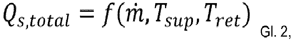
- the supply side demand is a function of the liquid feed temperature (T sup ), the liquid return temperature (T ret ), and the liquid flow rate (m).
- the HVAC system may include a liquid for heat transfer to the chiller and, for example, between the supply side and the demand side, the liquid may be liquid, for example substantially comprising water.
- the demand estimator may be independent of other demand side parameters, such as: zone dimensions, zone volume, zone range, zone heat capacity, or a combination thereof.
- the method according to the invention may include adding at least one additional demand subsystem to the HVAC system, and thus to the demand side of the HVAC system.
- the method may further include establishing the signal communication between the additional demand subsystem and the supply side so that the additional requirements subsystem may perform the following step: communicating the demand from the additional demand subsystem to the supply side.
- the method according to the invention may include a supply side reaction time.
- the supply side may be configured to operate in: i) a first mode wherein at least one demand (Q D ) is received; and ii) in a second mode, wherein no demand (Q D ) is received.
- the supply side may be configured to increase response time when operating in the first mode and recognizing a second mode, and reducing response time when operating in the second mode and detecting a first mode.
- FIG. 12 illustrates a flowchart of a method according to various embodiments of the invention.
- a method step 10 the determination of the requirement Q D is carried out in the requirement subsystem.
- the demand Q D determined in step 10 is communicated to the supply side in step 11.
- the supply side operating power is determined based on the demand received by the supply subsystem from the supply subsystem.
- FIG. 12 is a diagram illustrating a method performed on a demand subsystem according to various embodiments of the invention at the demand subsystem.
- FIG. A controller 142 is configured to set the setpoint T set of a zone property, for example, a desired zone temperature, e.g. B. set by a user in an office room to receive.
- the controller is also configured to receive the current T ZONE value of the zone property.
- the controller determines the control signal u ctrl in a step 22.
- the control signal is used by the demand subsystem to set its operating state, which control signal could refer to a valve opening or fan speed.
- the control signal may be a normalized value from 0 to 1.
- the control signal u ctrl is communicated to the demand page processor 144.
- the demand page processor 144 determines the demand (Q D ), e.g. By assessing a demand estimator, wherein the demand estimator comprises a variable input, and wherein the variable input of the demand function comprises the current value T ZONE of the zone characteristic and the control signal (u ctrl ).
- the current value of the zone property can be measured value, for example from a temperature sensor.
- the measured value may be measured by a conventional sensor (such as a conventional temperature sensor), where both the controller 142 and the demand side processor may use the same measured value.
- T set is the temperature setpoint of a zone while T ZONE is the current temperature.
- the control signal u ctrl is greater than zero, and works the demand side, e.g. B. FCU, with a respective power greater than zero, z. B. with a higher fan speed than zero RPM.
- Eq. 1 is preferably used for an FCU, where Q D is the Q FCU , T ZONE is the zone temperature in Celsius, Q max is the maximum power in watts, and u ctrl is the normalized valve opening or normalized fan speed.
- the demand estimator (eg, Eq.1) is a function that provides the needs of the demand subsystem given arguments including temperature and control signal.
- the function may be applied in step 24 in the required subsystem processor in various forms, e.g. In the form of a mathematical calculation or in the form of an input-output table.
- FIG. 12 is a diagram illustrating at least three need subsystems 151, 152, 153 in communication with a supply side 111 according to various embodiments of the invention.
- the first needs subsystem 151 is configured to determine a first control signal u ctrl, 1 in step 31, to determine (with a processor of the first needs subsystem) a corresponding first demand Q D1 in step 32 and to communicate the first demand to the supply side 111.
- the second requirements subsystem 152 is configured to determine a second control signal u ctrl, 2 in step 33, to determine a corresponding second demand Q D2 (with a processor of the second demand subsystem) in step 34 and to communicate the second demand to the supply side 111.
- the demand subsystem 153 is configured to determine a third control signal u ctrl, 3 in step 35, to determine a corresponding third demand Q D3 (with a processor of the third required subsystem ) in step 36 and to communicate the third demand to the supply side 111.
- the HVAC system is not limited to three requirement subsystems and could include a single requirements subsystem as well as a plurality of demand subsystems, for example, 10 or more requirement subsystems.
- At least one of the needs may be the need for an FCU (Q FCU ) be.
- One of the needs may be a need for an air handling unit (Q AHU ). Therefore, instead of the aggregated delayed reaction time on the supply side (eg, the refrigeration system) given by the return fluid circuit and the averaging of the temperature measurements on the supply side (eg, the refrigeration system), the supply side of the present invention can determine its supply side operation without delay , Thus, an increase in supply side operating power can be made as needed with minimal reaction time, and the lowering can also be done with minimal reaction time. In this way, the invention provides for a faster response while allowing energy savings.
- the supply function (for example, equation 3) is a function that provides the supply operating power (Q S, total ) for given arguments including the demand (Q DX ).
- the utility function can be applied in the supply side processor in various forms, e.g. In the form of a mathematical calculation or in the form of an input-output table.
- FIG. 4 shows a diagram illustrating an HVAC system with various components according to a comparative example.
- the HVAC system may be divided into a supply side 111 and a demand side 141.
- the supply side may include a chiller 112 (eg, a refrigeration system) and a building management system (BMS) 114, which may be configured to be in signal communication 103 with the chiller 112.
- the supply side may include one or more demand subsystems, for example, a first FCU 151, a second FCU 152, a third FCU 153, and an AHU 160.
- the HVAC system may further include a circuit for conveying the liquid (eg, refrigerant, such as refrigerant) Water), which circuit may include a feed subcycle 101 and a return subcycle 102.
- liquid eg, refrigerant, such as refrigerant
- the refrigeration system 112 delivers, for example, cooled liquid to the feed subcirculation 101 to the demand side 141.
- the refrigeration system receives the return liquid via the Return subcircuit 102, and the return liquid can be cooled at the refrigeration system and fed again to the feed subcircuit 101.
- FIG. 5 shows a diagram of FIG. 4 however, at least one, preferably each, of the needs subsystems 151, 152, 153, and 160 includes a demand side processor that is responsible for determining the respective demand Q 151 , Q 152 , Q 153, and Q 160 and communicating the need for the supply side, Example to BMS 114, is configured.
- the supply side may include a supply side processor 124 that is configured to determine the supply requirement and thus to determine the supply side operating power.
- the liquid may be part of the closed loop, with the closest loop having a pump for providing the liquid stream.
- the pump may be part of the supply side, and may be integrated with the chiller or disconnected from the chiller.
- FIG. 6 shows an example of the course of the supply side operating power, in this case the cooling power, after switching on the HVAC system.
- FIG. 6 shows an upper graph 60 and a lower graph 61. In both the upper graph and the lower graph, the time on the horizontal axis is plotted in hours. On the vertical axis of the upper graph 60, the cooling capacity (in MW) is plotted, and on the vertical axis of the lower graph 61, the zone temperature is plotted in Celsius.
- the upper graph shows a dotted line 63 (with dots represented by "X"), which is a graph of cooling performance versus time as measured for a comparative example.
- the solid curve 62 represents the course of the simulated cooling performance versus time for the same comparative example. Measured and simulated courses are very comparable. Dashed line 64 represents the step setpoint.
- the HVAC system will be turned on for approximately 7.5 hours. Although the demand is available at startup, the system can provide the immediate cooling demand from the Water temperature difference do not recognize. The second stage does not begin until about 8 because the buffer has expired at that time and the staged setpoint 64 has been crossed.
- the invention can also be realized with a zone property other than the zone temperature given as an example herein.
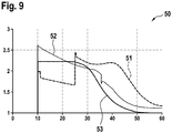
- FIG. 9 Figure 4 shows a graph 50 with the capacity of a chiller in MW on the vertical axis and the time in minutes on the horizontal axis.
- Curve 51 is the measurement of the capacity of the refrigerator of a conventional system
- curve 52 is the measurement of the capacity of the refrigerator of the method according to the invention.
- Curve 53 is the estimated requirement according to the present invention.
- the second stage with the method according to the invention achieves a maximum performance compared to the comparative example very quickly.
- the chiller since the chiller receives the demand information from the demand side, it can quickly adjust the performance of the chiller stages to the required demand while the chiller in the comparative example reacts to the temperature of the return water, which is very slow in comparison.
- the example according to the invention regulates very quickly to a stable power, and even switches off the second stage.
- the comparative example turns off the second stage much later.
- Fig. 9 shows that for the conventional system, after starting (at 10 minutes) the first stage of the chiller, when working at full power, the full capacity can not be handled and therefore the second stage starts at about 25 minutes.
- the reason for the increased reaction time is the chill cycle process buffer as discussed above.
- the refrigeration device provides the precise operating performance and thus the exact cooling capacity, as shown in FIG.
- the chiller uses the first and second stages from startup with gradually decreasing the capacity to accommodate the gradually decreasing demand to stop the second stage (at about 15 minutes) much earlier than the conventional system.
- the system of the invention can achieve the desired zone conditioning temperature at the estimated demand side much earlier.
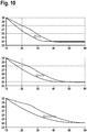
- FIG. 10 shows the course of the zone temperature for three different zone loads.
- the temperature in ° C on the vertical axis, the time in minutes on the horizontal axis, the dashed curves are the zone temperature curves of a zone cooled by a conventional method and / or system, and the solid lines are the zone temperature curves of the same by one method and / or system cooled according to the present invention.
- FIG. 10 shows in the middle of a reference zone, wherein it can be clearly seen that the cooling with the method and / or system according to the invention is much faster.
- the upper graph shows the same gradients for a zone that is less loaded, and the lower graph shows the same gradients for a zone that is more stressed.
- the arrows indicate reaching 25 ° C, it being understood that the invention is better in all three states and reaches a comfortable temperature of 25 ° C 5 to 10 minutes earlier than the prior art.
Landscapes
- Engineering & Computer Science (AREA)
- Chemical & Material Sciences (AREA)
- Combustion & Propulsion (AREA)
- Mechanical Engineering (AREA)
- General Engineering & Computer Science (AREA)
- Signal Processing (AREA)
- Physics & Mathematics (AREA)
- Fuzzy Systems (AREA)
- Mathematical Physics (AREA)
- Air Conditioning Control Device (AREA)
Abstract
Description
- Die vorliegende Offenbarung betrifft ein Heiz-, Lüftungs- und Klimaanlagensystem (Heating, Ventilation, and Air Conditioning System, HVAC-System), ein Bedarfssubsystem für ein HVAC-System, eine Versorgungsseite und ein Verfahren zum Betreiben eines HVAC-Systems.
- Ein übliches HVAC-System in einem beispielsweise gewerblichen Gebäude kann Kälteanlagen, Kühlturm, Luftbehandlungseinheiten (Air Handling Units, AHU) und Gebläsekonvektoren (Fan Coil Units, FCU) umfassen. Ein Gebäudemanagementsystem (Building Management System, BMS) steuert die Vorrichtungen durch Vorgabe von Sollwerten oder Plänen. Die FCUs an den Zonen im Gebäude können durch das BMS direkt oder lokal durch einen Thermostat gesteuert werden. Im normalen Betriebsmodus eines Gebäudes: i. werden die gewünschten Temperatursollwerte der Zonen im BMS oder an den lokalen Thermostaten eingestellt; ii. beginnt die Kälteanlage zu arbeiten, um Kühlwasser (Kaltwasser) mit einer festgelegten Temperatur zu liefern; iii. öffnet das Ventil an der FCU, um Kühlwasserfluss zum Abkühlen des Raums auf die gewünschte Temperatur zu ermöglichen; iv. empfängt die Kälteanlage Rücklaufkühlwasser mit einer höheren Temperatur; und v. definiert die Differenz zwischen der Versorgungs- (Vorlauf-) und Rücklauftemperatur die Kühllast des Gebäudes und den Arbeitsmodus der Kälteanlage. Die Informationen werden auch zur Planung der Kälteanlagenstufung verwendet, wenn die Last die Schwellenkapazität bereits überschreitet.
- Im Kälteanlagenstufungsprozess ist ein Puffer vorgesehen, um unerwünschte Stufung (Taktung) wegen Schwankung der Rücklaufkühlwassertemperatur zu vermeiden. Die Pufferzeit induziert eine Verzögerung zwischen dem zunehmenden Bedarf und der Kühlwasserversorgung. Dadurch wird die Systemreaktion verlangsamt.
- Dementsprechend besteht ein Bedarf, ein HVAC-System und ein Verfahren zum Betreiben eines HVAC-Systems mit einer schnelleren System-Reaktionszeit bereitzustellen.
- Die vorliegende Offenbarung betrifft ein Verfahren zum Betreiben eines HVAC-Systems. Das HVAC-System kann wenigstens ein Bedarfssubsystem in Signalkommunikation mit einer Versorgungsseite einschließen. Beispielsweise umfasst das HVAC-System als Bedarfssubsystem einen Verbraucher, beispielsweise eine kälteabnehmende Einheit. Das Verfahren kann einen Schritt des Bestimmens eines Bedarfs (QD) mit einer Bedarfsschätzfunktion einschließen. Die Bestimmung des Bedarfs kann von einem im Bedarfssubsystem eingeschlossenen Bedarfsseitenprozessor ausgeführt werden. Der variable Eingang der Bedarfsfunktion kann eine Zoneneigenschaft und ein Steuersignal (uctrl) umfassen. Das Verfahren kann Kommunizieren des Bedarfs (QD) vom Bedarfssubsystem zur Versorgungsseite einschließen. Das Verfahren kann Bestimmen einer Versorgungsseitenbetriebsleistung (Qs,total) als Funktion des Bedarfs (QD) und von Versorgungsseitenparametern einschließen; wobei die Bestimmung von einem in der Versorgungsseite eingeschlossenen Versorgungsseitenprozessor ausgeführt wird.
- Die vorliegende Offenbarung betrifft auch ein Bedarfssubsystem und eine Versorgungsseite, die dazu eingerichtet sind, miteinander zu kommunizieren. Die vorliegende Offenbarung betrifft auch ein HVAC-System einschließend die Versorgungsseite und wenigstens das Bedarfssubsystem.
- Das Bedarfssubsystem gemäß der vorliegenden Offenbarung eignet sich für ein HVAC-System, das dazu konfiguriert ist, operativ mit einer Versorgungsseite des HVAC-Systems zu kommunizieren. Das Bedarfssubsystem kann einen Controller zum Bereitstellen eines Steuersignals (uctrl) einschließen. Das Bedarfssubsystem kann einen Bedarfsseitenprozessor einschließen, der dazu konfiguriert ist, in der Lage zu sein, einen Bedarf (QD) mit einer Bedarfsschätzfunktion zu berechnen, z. B. durch Bewerten der Bedarfsschätzfunktion. Der variable Eingang der Bedarfsfunktion kann eine Zoneneigenschaft und das Steuersignal (uctrl) einschließen. Das Bedarfssubsystem kann einen Bedarfsseitensender zum Senden des Bedarfs (QD) zur Versorgungsseite einschließen.
- Die Versorgungsseite kann dazu konfiguriert werden, operativ mit wenigstens einem Bedarfssubsystem gemäß dieser Offenbarung zu kommunizieren. Die Versorgungsseite kann einen Versorgungsseitenempfänger zum Empfangen des Bedarfs (QD) vom Bedarfssubsystem einschließen. Das Versorgungssystem kann einen Versorgungsseitenprozessor (124) einschließen, der dazu konfiguriert ist, in der Lage zu sein, eine Versorgungsseitenbetriebsleistung (Qs,total) als Funktion des Bedarfs (QD) und von Versorgungsseitenparametern zu bestimmen.
- Das erfindungsgemäße HVAC-System kann eine Versorgungsseite und wenigstens das Bedarfssubsystem einschließen. Das HVAC-System kann zusätzliche erfindungsgemäße Bedarfssubsysteme einschließen.
- In der folgenden Beschreibung werden verschiedene Ausführungsformen der vorliegenden Offenbarung unter Bezug auf die folgenden Figuren dargestellt, wobei:
-
Figur 1 ein Ablaufdiagramm eines Verfahrens gemäß verschiedenen Ausführungsformen der Erfindung zeigt. -
Figur 2 ein Diagramm zur Veranschaulichung eines Verfahrens gemäß verschiedenen Ausführungsformen der Erfindung beim Bedarfssubsystem zeigt. -
Figur 3 ein Diagramm zur Veranschaulichung von wenigstens drei Bedarfssubsystemen in Kommunikation mit einer Versorgungsseite gemäß verschiedenen Ausführungsformen der Erfindung zeigt. -
Figur 4 ein Diagramm zur Veranschaulichung eines HVAC-Systems mit verschiedenen Komponenten gemäß einem Vergleichsbeispiel zeigt. -
Figur 5 ein Diagramm zur Veranschaulichung eines HVAC-Systems mit verschiedenen Komponenten gemäß einem Beispiel der Erfindung zeigt. -
Figur 6 ein Beispiel für den Verlauf einer Versorgungsseitenbetriebsleistung, in diesem Fall der Kühlleistung, nach Einschalten des HVAC-Systems, in einem Vergleichsbeispiel zeigt. - Jede der
Figuren 7 und 8 als ein Beispiel die Kühlleistung in kW (vertikale Achse) als Funktion des Steuersignals (horizontale Achse) für eine FCU mit einer Zonentemperatur TZONE = 24 °C inFigur 7 und TZONE = 29 °C inFigur 8 zeigt. -
Figur 9 einen Graphen 50 zeigt, der die Kapazität einer Kälteanlage in MW auf der vertikalen Achse und die Zeit in Minuten auf der horizontalen Achse darstellt. -
Figur 10 den Verlauf der Zonentemperatur für drei verschiedene Zonenlasten zeigt. - In der folgenden detaillierten Beschreibung werden spezifische Einzelheiten und Ausführungsformen, in denen die Erfindung ausgeübt werden kann, beschrieben. Diese Ausführungsformen werden in ausreichendem Detail beschrieben, um einem Fachmann die Ausübung der Erfindung zu ermöglichen. Andere Ausführungsformen können genutzt und Änderungen können vorgenommen werden, ohne vom Umfang der Erfindung abzuweichen. Die verschiedenen Ausführungsformen schließen sich nicht notwendigerweise gegenseitig aus, da einige Ausführungsformen mit einer oder mehreren anderen Ausführungsformen kombiniert werden können, um neue Ausführungsformen zu bilden.
- Merkmale, die im Rahmen einer Ausführungsform beschrieben sind, können entsprechend auf dieselben oder ähnliche Merkmale bei anderen Ausführungsformen anwendbar sein. Merkmale, die im Rahmen einer Ausführungsform beschrieben sind, können entsprechend auf die anderen Ausführungsformen anwendbar sein, auch wenn dies bei diesen anderen Ausführungsformen nicht ausdrücklich beschrieben ist. Ferner können Hinzufügungen und/oder Kombinationen und/oder Alternativen, wie für ein Merkmal im Rahmen einer Ausführungsform beschrieben, entsprechend auf dasselbe oder ein ähnliches Merkmal bei anderen Ausführungsformen anwendbar sein.
- Der Ausdruck "variabler Eingang" kann sich auf die Argumente einer Funktion beziehen.
- Die hierin veranschaulichend beschriebene Erfindung kann in geeigneter Weise bei Abwesenheit eines beliebigen Elements oder beliebiger Elemente, einer beliebigen Einschränkung oder beliebiger Einschränkungen, die nicht eigens hierin offenbart sind, ausgeübt werden. Daher sind zum Beispiel die Begriffe "umfassend", "einschließlich", "enthalten" etc. expansiv und ohne Einschränkung aufzufassen. Das Wort "umfassen" oder Variationen, wie "umfasst" oder "umfassend", wird dementsprechend so verstanden, dass es die Einbeziehung einer angegebenen ganzen Zahl oder von Gruppen ganzer Zahlen impliziert, nicht aber den Ausschluss einer beliebigen anderen ganzen Zahl oder Gruppe ganzer Zahlen. Außerdem sind die hierin vorkommenden Begriffe und Ausdrücke als Begriffe der Beschreibung und nicht der Einschränkung verwendet, und bei der Verwendung dieser Begriffe und Ausdrücke besteht keine Absicht des Ausschließens jeglicher Äquivalente der gezeigten und beschriebenen Merkmale oder Teile davon, aber es wird erkannt, dass verschiedene Modifikationen innerhalb des Umfangs der beanspruchten Erfindung möglich sind. Somit sollte klar sein, dass, obwohl die vorliegende Erfindung spezifisch durch beispielhafte Ausführungsformen und optionale Merkmale offenbart worden ist, der Fachmann Modifikationen und Variationen der hierin verkörperten und offenbarten Erfindungen vornehmen kann, und dass derartige Modifikationen und Variationen als im Umfang dieser Erfindung liegend betrachtet werden.
- Die in den Ansprüchen in Klammern angegebenen Bezugszeichen dienen zum leichteren Verständnis der Erfindung und haben keine einschränkende Auswirkung auf den Umfang der Ansprüche.
- Die weiteren in den Ansprüchen und in der Beschreibung in Klammern angegebenen Bezugszeichen dienen zum leichteren Verständnis der Erfindung und haben keine einschränkende Auswirkung auf den Umfang der Erfindung, insbesondere keine einschränkende Auswirkung auf den Umfang der Ansprüche. Diese weiteren Bezugszeichen haben dieselbe Wirkung wie Bezugszeichen. Die weiteren Bezugszeichen können von den Ansprüchen gelöscht werden, ohne den Umfang der Ansprüche zu beeinträchtigen. Beispiele für solche weiteren Bezugszeichen sind QD, Qs,total, TZONE, QAHU, Tair, AHamb, uctrl, ufan, uvalve, Tsup, Tret, m, Q152 und Q153.
- Die Abkürzungen HVAC, AHU, FCU und BMS, wie in der vorliegenden Offenbarung verwendet, sind Begriffe mit im Gebiet wohlbekannten Bedeutungen. HVAC (Heating, Ventilation, Air Conditioning) steht für Heiz-, Lüftungs- und Klimaanlagensystem. AHU (Air Handling Unit) steht für Luftbehandlungseinheit. FCU (Fan Coil Unit) steht für Gebläsekonvektor. BMS (Building Management System) steht für Gebäudemanagementsystem.
- Bei verschiedenen Ausführungsformen kann das HVAC-System in eine Bedarfsseite und eine Versorgungsseite unterteilt werden.
- Bei verschiedenen Ausführungsformen kann das HVAC-System wenigstens ein Bedarfssubsystem in Signalkommunikation mit einer Versorgungsseite einschließen. Ein Bedarfssubsystem kann ein Klimagerät sein. Ein Beispiel für ein Klimagerät ist ein Gebläsekonvektor. Ein weiteres Beispiel für ein Klimagerät ist eine Luftbehandlungseinheit. Ein Beispiel für ein Bedarfssubsystem ist ein Gebläsekonvektor (Fan Coil Unit, FCU). Ein Beispiel für eine Versorgungsseite schließt ein Gebäudemanagementsystem (Building Management System, BMS) und einen Kälteerzeuger (z. B. eine Kälteanlage) ein.
- Bei verschiedenen Ausführungsformen sind das Bedarfssubsystem und ein oder mehrere zusätzliche Bedarfssubsysteme in der Bedarfsseite eingeschlossen. Bei verschiedenen Ausführungsformen kann das HVAC-System ein oder mehrere zusätzliche Bedarfssubsysteme einschließen, wobei dieses zusätzliche eine oder jedes dieser zusätzlichen mehreren Bedarfssubsysteme vorzugsweise den erfindungsgemäßen Bedarfssubsystemen entspricht.
- Bei verschiedenen Ausführungsformen kann das Bedarfssubsystem den Bedarfsseitenprozessor einschließen. Der Bedarfsseitenprozessor ist dazu konfiguriert, die Bestimmung des Bedarfs (QD) mit der Bedarfsschätzfunktion auszuführen, z. B. durch Bewerten der Funktion. Die Bedarfsschätzfunktion umfasst den variablen Eingang. Der variable Eingang der Bedarfsfunktion umfasst eine Zoneneigenschaft und das Steuersignal (uctrl). Die Bedarfsschätzfunktion wird hierin auch einfach "Bedarfsfunktion" genannt.
- Bei der vorliegenden Offenbarung wird eine Temperatur, wie eine Zonentemperatur (TZONE), zum Erklären der Erfindung als eine mögliche Zoneneigenschaft verwendet, die Erfindung ist aber nicht hierauf eingeschränkt, und eine andere Zoneneigenschaft kann als die Zoneneigenschaft oder die Zonentemperatur verwendet werden, zum Beispiel die Luftfeuchtigkeit der Zone, die relative Luftfeuchtigkeit der Zone, der Taupunkt der Zone, die CO2-Konzentration der Zone oder Kombinationen davon. In einem Beispiel ist die Eigenschaft der Zone die Temperatur der Zone (TZONE).
- Bei verschiedenen Ausführungsformen kann sich Zoneneigenschaft auf Eigenschaften der Luft in der jeweiligen Zone beziehen.
- Bei verschiedenen Ausführungsformen ist die Zoneneigenschaft eine Umgebungsvariable der Zone. Daher schließt die Zoneneigenschaft nicht variable Eigenschaften der Zone aus, wie zum Beispiel: Zonenabmessungen, Zonenvolumen, Zonenbereich, Zonenwärmekapazität oder eine Kombination davon. Die Zoneneigenschaft kann einer Eigenschaft der Luft in der jeweiligen Zone entsprechen. Der Begriff "entsprechen" kann in diesem Zusammenhang bedeuten, dass es sich bei der Zoneneigenschaft um eine bestimmte Eigenschaft handelt. "Zoneneigenschaft entspricht der Zonentemperatur" kann zum Beispiel bedeuten, dass die Zoneneigenschaft die Zonentemperatur ist. In einem anderen Beispiel kann "Zoneneigenschaft entspricht einer Luftfeuchtigkeit" bedeuten, dass die Zoneneigenschaft die Zonenluftfeuchtigkeit ist.
- Die Temperatur ist die gemessene aktuelle Temperatur (im Gegensatz zu einer Soll-Temperatur). Beispielsweise ist die Temperatur für eine FCU die von der FCU gemessene Zonentemperatur (Tzone). Das Steuersignal kann das Signal von einem Controller des Bedarfsseitensubsystems einschließen. Der Eingang des Controllers schließt einen Sollwert, z. B. einen Temperatursollwert (Tset), und die Zonentemperatur (z. B. die aktuelle gemessene Temperatur der Zone) ein. Der Controller erzeugt ein Steuersignal, das eine Funktion des Eingangs zum Controller ist. Das Steuersignal kann zum Beispiel einer Lüfterdrehzahl oder einer Ventilöffnung entsprechen. Der Begriff "entsprechen" kann in diesem Zusammenhang bedeuten, dass es sich beim Steuersignal um eine Lüfterdrehzahl oder eine Ventilöffnung handelt. Beim Steuersignal kann es sich zum Beispiel um eine Lüfterdrehzahl oder ein Ventilöffnungsverhältnis handeln.
- Bei verschiedenen Ausführungsformen kann das Bedarfssubsystem den Sender zum Senden des Bedarfs (QD) zur Versorgungsseite einschließen.
- Bei verschiedenen Ausführungsformen kann die Versorgungsseite den Empfänger zum Empfangen des Bedarfs (QD) vom Bedarfssubsystem einschließen.
- Bei verschiedenen Ausführungsformen kann sich Kommunizieren des Bedarfs auf Senden des Bedarfs über den Sender vom Bedarfsseitensubsystem zum Empfänger der Versorgungsseite beziehen. Somit wird die Signalkommunikation zwischen dem Sender und dem Empfänger hergestellt.
- Bei verschiedenen Ausführungsformen kann die Versorgungsseite den Versorgungsseitenprozessor einschließen. Der Versorgungsseitenprozessor kann dazu konfiguriert werden, in der Lage zu sein, eine Versorgungsseitenbetriebsleistung als Funktion des Bedarfs (QD) zu bestimmen. Die Bestimmung kann andere Parameter, wie Versorgungsseitenparameter, einschließen. Typischerweise reichen der Bedarf (QD) und die Versorgungsseitenparameter aus, um die Versorgungsseitenbetriebsleistung zu berechnen. Wenn zusätzliche Bedarfsseitensubsysteme vorhanden sind, schließt Bedarf (QD) hierin auch zusätzliche Bedarfe ein. Der Ausdruck "in der Lage zu sein" hierin bedeutet, dass der Versorgungsseitenprozessor, wenn das HVAC-System in Betrieb ist, und bei Verfügbarkeit des Bedarfs (QD) gemäß Empfang durch den Empfänger, die Betriebsleistung (Qs,total) bestimmt. Die Betriebsleistung (Qs,total) ist eine Funktion des Bedarfs, z. B. proportional zum Bedarf. Die Betriebsleistung (Qs,total) kann proportional zur Summe der Bedarfe sein. Die Bestimmung der Betriebsleistung kann zum Beispiel Variieren der Drehzahl einer Motorpumpe und Aktivieren oder Deaktivieren von zusätzlichen Stufen neben einer Hauptstufe einer Kälteanlage einschließen. Versorgungsseitenparameter sind zum Beispiel für den Betrieb der Versorgungsseite erforderliche Parameter, die nicht von oder zu der Bedarfsseite kommuniziert werden müssen. Beispiele für Versorgungsseitenparameter sind die Beziehung zwischen der Betriebsleistung und der Kapazität einer Kälteanlage, die Temperatur des Rücklaufwassers und einschränkende Faktoren wie Höchstleistung einer Pumpe oder Kälteanlage. Die Betriebsleistung kann durch eine versorgungsseitige Betriebsleistungsschätzfunktion, hierin auch einfach "Versorgungsfunktion" genannt, bestimmt werden.
- Gemäß der Erfindung kann ein HVAC-System bereitgestellt werden, wobei das HVAC-System die Versorgungsseite einschließt, und die Versorgungsseite dazu konfiguriert ist, operativ mit wenigstens dem Bedarfssubsystem, vorzugsweise weiterhin mit den zusätzlichen Bedarfssubsystemen zu kommunizieren.
- Bei verschiedenen Ausführungsformen für das HVAC-System kann das HVAC-System wenigstens das Bedarfssubsystem, vorzugsweise weiterhin ein zusätzliches Bedarfssubsystem, einschließen.
- Bei verschiedenen Ausführungsformen der Erfindung wird das Bedarfssubsystem gewählt unter wenigstens einem von: Gebläsekonvektor und Luftbehandlungseinheit.
- Verschiedene Ausführungsformen der Erfindung können ein Verfahren zum Betreiben des HVAC-Systems betreffen. Das Verfahren kann einschließen: a) Bestimmen des Bedarfs (QD) mit der Bedarfsschätzfunktion, wobei die Bestimmung von einem im Bedarfssubsystem eingeschlossenen Bedarfsseitenprozessor ausgeführt wird; wobei die Bedarfsschätzfunktion den variablen Eingang umfasst, und wobei der variable Eingang der Bedarfsfunktion die Zoneneigenschaft, z. B. eine Temperatur, und das Steuersignal (uctrl) umfasst. Die Temperatur ist vorzugsweise eine Zonentemperatur (TZone), ein Beispiel für eine Zonentemperatur ist eine Raumtemperatur (TR), wobei der Raum eine einzelne Zone umfassen kann. Das Verfahren kann einschließen: b) Kommunizieren des Bedarfs (QD), der in Schritt a) bestimmt wurde, vom Bedarfssubsystem zur Versorgungsseite. Das Verfahren kann einschließen: c) Bestimmen der Versorgungsseitenbetriebsleistung als Funktion des Bedarfs (QD) und von Versorgungsseitenparametern; wobei die Bestimmung durch einen in der Versorgungsseite eingeschlossenen Versorgungsseitenprozessor ausgeführt wird.
- Bei verschiedenen Ausführungsformen der Erfindung kann das Bedarfssubsystem eine FCU sein, und die Temperatur ist eine Zonentemperatur. Die Zonentemperatur kann eine Raumtemperatur (TR) sein, z. B. wenn der Raum eine einzelne Zone umfasst.
- Bei verschiedenen Ausführungsformen der Erfindung kann das Bedarfssubsystem eine Luftbehandlungseinheit (AHU) sein, wobei der Bedarf ein AHU-Bedarf (QAHU) ist, und der Bedarfsseitenprozessor ein in der Luftbehandlungseinheit eingeschlossener AHU-Seitenprozessor ist, wobei die Bedarfsschätzfunktion eine AHU-Bedarfsfunktion ist. Der variable Eingang der AHU-Bedarfsfunktion kann weiterhin die Luftfeuchtigkeit (AHamb) umfassen.
- Bei verschiedenen Ausführungsformen, vorzugsweise wenn das Bedarfssubsystem eine AHU einschließt, kann das Bedarfssubsystem ein zweites Steuersignal einschließen, wobei es sich bei der Temperatur im Bedarfssubsystem um die Temperatur der Versorgungsluft (Tair) handelt, zum Beispiel die Außenumgebungstemperatur, das Steuersignal (uctrl) einer Lüfterdrehzahl (ufan) entspricht und das zweite Steuersignal einer Ventilöffnung (uvalve) entspricht.
- Bei verschiedenen Ausführungsformen kann die Bedarfsseite ein Bedarfssubsystem, das eine AHU ist, und weiterhin eine Mehrzahl von Bedarfssubsystemen, die jeweils eine FCU sind, einschließen.
- Bei verschiedenen Ausführungsformen kann die Bedarfsseite eine Mehrzahl von Bedarfssubsystemen, die jeweils eine Luftbehandlungseinheit sind, und weiterhin eine Mehrzahl von Bedarfssubsystemen, die jeweils eine FCU sind, einschließen.
- Bei verschiedenen Ausführungsformen kann das HVAC-System einen Kälteerzeuger (z. B. eine Kälteanlage) auf der Versorgungsseite einschließen. Das Verfahren gemäß der Erfindung kann Bestimmen einer Betriebsleistung des Kälteerzeugers, z. B. der Betriebsleistung einer Kälteanlage, einschließen, wobei der Bedarf der Versorgungsseite eine Funktion der Zulauftemperatur der Flüssigkeit (Tsup), der Rücklauftemperatur der Flüssigkeit (Tret) und der Flussrate der Flüssigkeit (m) ist. Das HVAC-System kann eine Flüssigkeit für Wärmeübertragung am Kälteerzeuger und zum Beispiel zwischen der Versorgungsseite und der Bedarfsseite einschließen, die Flüssigkeit kann liquide sein, zum Beispiel im Wesentlichen Wasser umfassen.
- Bei verschiedenen Ausführungsformen kann die Bedarfsschätzfunktion unabhängig von anderen Bedarfsseitenparametern sein, wie: Zonenabmessungen, Zonenvolumen, Zonenbereich, Zonenwärmekapazität oder eine Kombination davon.
- Bei verschiedenen Ausführungsformen kann das Verfahren gemäß der Erfindung Hinzufügen wenigstens eines zusätzlichen Bedarfssubsystems zum HVAC-System und damit zur Bedarfsseite des HVAC-Systems einschließen. Das Verfahren kann weiterhin Herstellen der Signalkommunikation zwischen dem zusätzlichen Bedarfssubsystem und der Versorgungsseite einschließen, sodass das zusätzliche Bedarfssubsystem den nachstehenden Schritt ausführen kann: Kommunizieren des Bedarfs vom zusätzlichen Bedarfssubsystem zur Versorgungsseite.
- Bei verschiedenen Ausführungsformen kann das Verfahren gemäß der Erfindung eine Reaktionszeit für die Versorgungsseite umfassen. Die Versorgungsseite kann konfiguriert werden zum Arbeiten in: i) einem ersten Modus, wobei wenigstens ein Bedarf (QD) empfangen wird; und ii) in einem zweiten Modus, wobei kein Bedarf (QD) empfangen wird. Die Versorgungsseite kann dazu konfiguriert werden, beim Arbeiten im ersten Modus und Erkennen eines zweiten Modus die Reaktionszeit zu erhöhen, und beim Arbeiten im zweiten Modus und Erkennen eines ersten Modus die Reaktionszeit zu vermindern.
-
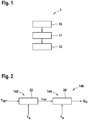
Fig. 1 veranschaulicht ein Ablaufdiagramm eines Verfahrens gemäß verschiedenen Ausführungsformen der Erfindung. In einem Verfahrensschritt 10 wird die Bestimmung des Bedarfs QD beim Bedarfssubsystem ausgeführt. In einem weiteren zu einem späteren Zeitpunkt als Schritt 10 ausgeführten Verfahrensschritt, wird in Schritt 11 der Bedarf QD, der in Schritt 10 bestimmt worden war, zur Versorgungsseite kommuniziert. In einem weiteren zu einem späteren Zeitpunkt als Schritt 11 ausgeführten Verfahrensschritt, wird in Schritt 12 die Versorgungsseitenbetriebsleistung anhand des durch die Versorgungsseite vom Bedarfssubsystem empfangenen Bedarfs bestimmt. -
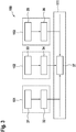
Fig. 2 zeigt ein Diagramm zur Veranschaulichung eines bei einem Bedarfssubsystem gemäß verschiedenen Ausführungsformen der Erfindung am Bedarfssubsystem ausgeführten Verfahrens. Ein Controller 142 ist dazu konfiguriert, den Sollwert Tset einer Zoneneigenschaft, zum Beispiel einer gewünschten Zonentemperatur, z. B. durch einen Benutzer in einem Büroraum eingestellt, zu empfangen. Der Controller ist auch dazu konfiguriert, den aktuellen Wert TZONE der Zoneneigenschaft zu empfangen. Anhand dieser beiden Eingänge bestimmt der Controller in einem Schritt 22 das Steuersignal uctrl. Das Steuersignal wird vom Bedarfssubsystem zum Einstellen seines Betriebszustands verwendet, wobei sich das Steuersignal auf eine Ventilöffnung oder eine Lüfterdrehzahl beziehen könnte. Das Steuersignal kann ein normierter Wert von 0 bis 1 sein. Das Steuersignal uctrl wird zum Bedarfsseitenprozessor 144 kommuniziert. Der Bedarfsseitenprozessor 144 bestimmt den Bedarf (QD), z. B. durch Bewerten einer Bedarfsschätzfunktion, wobei die Bedarfsschätzfunktion einen variablen Eingang umfasst, und wobei der variable Eingang der Bedarfsfunktion den aktuellen Wert TZONE der Zoneneigenschaft und das Steuersignal (uctrl) umfasst. Der aktuelle Wert der Zoneneigenschaft kann ein gemessener Wert sein, zum Beispiel von einem Temperatursensor. Der gemessene Wert kann durch einen üblichen Sensor (wie z. B. durch einen üblichen Temperatursensor) gemessen werden, wobei sowohl der Controller 142 als auch der Bedarfsseitenprozessor denselben gemessenen Wert verwenden können. - In einem Beispiel ist Tset der Temperatursollwert einer Zone, während TZONE die aktuelle Temperatur ist. Das Steuersignal kann bestimmt werden durch uctrl=f(Tset,TZONE), zum Beispiel im Kühlmodus, das uctrl = a1(TZONE - Tset), wobei a1 ein Normierungsfaktor ist. Das Steuersignal uctrl kann begrenzt werden, zum Beispiel dann, wenn TZONE <= Tset, kann das Steuersignal null sein. Somit, wenn TZONE > Tset, ist das Steuersignal uctrl größer als null, und arbeitet die Bedarfsseite, z. B. FCU, mit einer jeweiligen Leistung größer als null, z. B. mit einer höheren Lüfterdrehzahl als null U/min.
- In einem Beispiel wird der Bedarf mit einer Funktion QD=f(uctrl,TZONE) bestimmt, wie folgt:

- Bei verschiedenen Ausführungsformen ist die Bedarfsschätzfunktion (zum Beispiel Gl. 1) eine Funktion, die bei gegebenen Argumenten einschließlich Temperatur und Steuersignal den Bedarf des Bedarfssubsystems liefert. Die Funktion kann in Schritt 24 im Bedarfssubsystemprozessor in verschiedenen Formen angewendet werden, z. B. in Form einer mathematischen Berechnung oder in Form einer Input-Output-Tabelle.
-
Fig. 3 zeigt ein Diagramm zur Veranschaulichung von wenigstens drei Bedarfssubsystemen 151, 152, 153 in Kommunikation mit einer Versorgungsseite 111 gemäß verschiedenen Ausführungsformen der Erfindung. Das erste Bedarfssubsystem 151 ist zum Bestimmen eines ersten Steuersignals uctrl,1 in Schritt 31, zum Bestimmen (mit einem Prozessor des ersten Bedarfssubsystems) eines entsprechenden ersten Bedarfs QD1 in Schritt 32 und zum Kommunizieren des ersten Bedarfs zur Versorgungsseite 111 konfiguriert. Das zweite Bedarfssubsystem 152 ist zum Bestimmen eines zweiten Steuersignals uctrl,2 in Schritt 33, zum Bestimmen eines entsprechenden zweiten Bedarfs QD2 (mit einem Prozessor des zweiten Bedarfssubsystems) in Schritt 34 und zum Kommunizieren des zweiten Bedarfs zur Versorgungsseite 111 konfiguriert. Das Bedarfssubsystem 153 ist zum Bestimmen eines dritten Steuersignals uctrl,3 in Schritt 35, zum Bestimmen eines entsprechenden dritten Bedarfs QD3 (mit einem Prozessor des dritten Bedarfssubsystems) in Schritt 36 und zum Kommunizieren des dritten Bedarfs zur Versorgungsseite 111 konfiguriert. Das HVAC-System ist nicht auf drei Bedarfssubsysteme eingeschränkt und könnte ein einzelnes Bedarfssubsystem sowie eine Mehrzahl von Bedarfssubsystemen, zum Beispiel 10 oder mehr Bedarfssubsysteme, einschließen. - Im Gegensatz zum herkömmlichen Weg der Bestimmung der Betriebsleistung der Versorgungsseite (z. B. des Bedarfs einer Kälteanlage) mittels der Funktion gemäß Gl. 2:

- Bei verschiedenen Ausführungsformen ist die Versorgungsfunktion (zum Beispiel Gl. 3) eine Funktion, die bei gegebenen Argumenten einschließlich der Bedarfe (QDX) die Versorgungsbetriebsleistung (QS,total) liefert. Die Versorgungsfunktion kann im Versorgungsseitenprozessor in verschiedenen Formen angewendet werden, z. B. in Form einer mathematischen Berechnung oder in Form einer Input-Output-Tabelle.
- Die oben erläuterten Funktionen Gl. 1, Gl. 2, Gl. 3 sind jeweils beispielhafte Ausführungsformen der Erfindung, die Erfindung ist aber nicht darauf eingeschränkt. Anhand der Lehren der vorliegenden Offenbarung kann der Fachmann verschiedene Funktionen innerhalb des Umfangs der Erfindung entwickeln.
-
Figur 4 zeigt ein Diagramm zur Veranschaulichung eines HVAC-Systems mit verschiedenen Komponenten gemäß einem Vergleichsbeispiel. Das HVAC-System kann in eine Versorgungsseite 111 und eine Bedarfsseite 141 unterteilt werden. Die Versorgungsseite kann einen Kälteerzeuger 112 (z. B. eine Kälteanlage) und ein Gebäudemanagementsystem (BMS) 114, das dazu konfiguriert sein kann, in Signalkommunikation 103 mit dem Kälteerzeuger 112 zu stehen, einschließen. Die Versorgungsseite kann ein oder mehrere Bedarfssubsysteme einschließen, zum Beispiel eine erste FCU 151, eine zweite FCU 152, eine dritte FCU 153 und eine AHU 160. Das HVAC-System kann ferner einen Kreislauf zum Befördern der Flüssigkeit (z. B. Kältemittel, wie Wasser) einschließen, wobei der Kreislauf einen Zulaufunterkreislauf 101 und einen Rücklaufunterkreislauf 102 einschließen kann. Beim Kühlen liefert die Kälteanlage 112 zum Beispiel gekühlte Flüssigkeit zum Zulaufunterkreislauf 101 zur Bedarfsseite 141. Die Kälteanlage empfängt die Rücklaufflüssigkeit über den Rücklaufunterkreislauf 102, und die Rücklaufflüssigkeit kann an der Kälteanlage abgekühlt und erneut dem Zulaufunterkreislauf 101 zugeführt werden. -
Figur 5 zeigt ein dem Diagramm vonFigur 4 ähnliches Diagramm, wobei jedoch wenigstens eines der, vorzugsweise jedes der Bedarfssubsysteme 151, 152, 153 und 160 einen Bedarfsseitenprozessor umfasst, der zum Bestimmen des jeweiligen Bedarfs Q151, Q152, Q153 sowie Q160 und zum Kommunizieren des Bedarfs zur Versorgungsseite, zum Beispiel zum BMS 114, konfiguriert ist. Bei verschiedenen Ausführungsformen kann die Versorgungsseite einen Versorgungsseitenprozessor 124 einschließen, der zum Bestimmen des Versorgungsbedarfs und somit zum Bestimmen der Versorgungsseitenbetriebsleistung konfiguriert ist. - Bei verschiedenen Ausführungsformen kann die Flüssigkeit Teil des geschlossenen Kreislaufs sein, wobei der nächstliegende Kreislauf eine Pumpe zum Bereitstellen des Flüssigkeitsstroms aufweist. Die Pumpe kann Teil der Versorgungsseite sein, und sie kann in den Kälteerzeuger integriert oder vom Kälteerzeuger getrennt sein.
-
Figur 6 zeigt ein Beispiel für den Verlauf der Versorgungsseitenbetriebsleistung, in diesem Fall der Kühlleistung, nach Einschalten des HVAC-Systems.Figur 6 zeigt einen oberen Graphen 60 und einen unteren Graphen 61. Sowohl beim oberen als auch beim unteren Graphen wird auf der horizontalen Achse die Zeit in Stunden abgetragen. Auf der vertikalen Achse des oberen Graphen 60 wird die Kühlleistung (in MW) abgetragen, und auf der vertikalen Achse des unteren Graphen 61 wird die Zonentemperatur in Celsius abgetragen. Der obere Graph zeigt eine gepunktete Linie 63 (mit durch "X" repräsentierten Punkten), die einen Verlauf der Kühlleistung gegenüber der Zeit, wie für ein Vergleichsbeispiel gemessen, darstellt. Die durchgezogene Kurve 62 repräsentiert den Verlauf der simulierten Kühlleistung gegenüber der Zeit für das gleiche Vergleichsbeispiel. Gemessene und simulierte Verläufe sind sehr vergleichbar. Die gestrichelte Linie 64 repräsentiert den Stufungssollwert. - Das HVAC-System wird ungefähr um 7,5 h eingeschaltet. Obwohl der Bedarf bei Start zur Verfügung steht, kann das System den unmittelbaren Kühlbedarf aus der Wassertemperaturdifferenz nicht erkennen. Die zweite Stufe beginnt erst ungefähr um 8, weil der Puffer zu dieser Zeit ausgelaufen ist, und der Stufungssollwert 64 gekreuzt wurde.
- Jede der
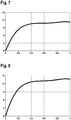
Figuren 7 und 8 zeigt als ein Beispiel die Kühlleistung in kW (vertikale Achse) als Funktion des Steuersignals (horizontale Achse) für eine FCU mit einer Zonentemperatur TZONE = 24 °C inFigur 7 und TZONE = 29 °C inFigur 8 . Diese Verläufe können für ein System gemessen oder simuliert sein. Nachdem die Beziehung zwischen der Kühlleistung und dem Steuersignal uctrl für eine gegebene Zonentemperatur TZONE bekannt ist, kann der Bedarf QD einfach durch Kenntnis des Steuersignals uctrl und der Zonentemperatur TZONE bestimmt werden. Die Erfindung kann auch mit einer anderen Zoneneigenschaft als der hierin als ein Beispiel gegebenen Zonentemperatur realisiert werden. -
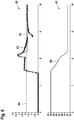
Figur 9 zeigt einen Graphen 50 mit der Kapazität eines Kälteerzeugers in MW auf der vertikalen Achse und der Zeit in Minuten auf der horizontalen Achse. Kurve 51 ist die Messung der Kapazität des Kälteerzeugers eines herkömmlichen Systems, während Kurve 52 die Messung der Kapazität des Kälteerzeugers des erfindungsgemäßen Verfahrens ist. Kurve 53 ist der geschätzte Bedarf gemäß der vorliegenden Erfindung. - Es ist ersichtlich, dass die zweite Stufe mit dem erfindungsgemäßen Verfahren eine Höchstleistung gegenüber dem Vergleichsbeispiel sehr schnell erreicht. Da der Kälteerzeuger erfindungsgemäß die Bedarfsinformationen von der Bedarfsseite empfängt, kann er die Leistung der Kälteerzeugerstufen schnell an den erforderlichen Bedarf anpassen, während der Kälteerzeuger im Vergleichsbeispiel auf die Temperatur des Rücklaufwassers reagiert, was im Vergleich sehr langsam ist. So regelt sich das erfindungsgemäße Beispiel sehr schnell auf eine stabile Leistung, und schaltet sogar die zweite Stufe aus. Das Vergleichsbeispiel hingegen schaltet die zweite Stufe erst viel später aus. Bei herkömmlichen Systemen kann eine weitere Verzögerung eingebaut sein (z. B. in Form einer Hysterese oder in Form eines gleitenden Durchschnitts, z. B. der Temperatur des Rücklaufwassers), um plötzliche Änderungen der Kühlleistung zu vermeiden, zum Beispiel wegen Wassertemperaturspitzen im System oder Fehlern bei Temperaturmessungen. Wegen dieser Verzögerung reagiert das herkömmliche HVAC-System sehr langsam.
-
Fig. 9 zeigt, dass für das herkömmliche System nach Starten (zur Zeit von 10 Minuten) der ersten Stufe des Kälteerzeugers bei Arbeiten mit voller Leistung nicht die volle Kapazität gehandhabt werden kann, und daher die zweite Stufe bei etwa 25 Minuten startet. Der Grund für die erhöhte Reaktionszeit ist der Kälteerzeugerstufungsprozesspuffer, wie oben erläutert. Da der Bedarf beim erfindungsgemäßen Verfahren und/oder System bekannt ist, stellt der Kälteerzeuger hingegen die genaue Betriebsleistung und damit die genaue Kühlkapazität bereit, wie im Verlauf 52 gezeigt. Ferner nutzt der Kälteerzeuger die erste und die zweite Stufe vom Start unter allmählicher Verminderung der Kapazität zur Anpassung an den allmählich abnehmenden Bedarf, um die zweite Stufe (bei etwa 15 Minuten) viel früher zu stoppen als das herkömmliche System. Das erfindungsgemäße System kann die gewünschte Zonenklimatisierungstemperatur bei der geschätzten Bedarfsseite viel früher zu erreichen. -
Figur 10 zeigt den Verlauf der Zonentemperatur für drei verschiedene Zonenlasten. In jedem der Graphen vonFigur 10 ist auf der vertikalen Achse die Temperatur in °C, auf der horizontalen Achse die Zeit in Minuten abgetragen, die gestrichelten Verläufe sind die Zonentemperaturkurven einer durch ein herkömmliches Verfahren und/oder System gekühlten Zone und die durchgezogenen Linien sind die Zonentemperaturkurven der gleichen durch ein Verfahren und/oder System gemäß der vorliegenden Erfindung gekühlten Zone.Figur 10 zeigt in der Mitte eine Referenzzone, wobei deutlich zu erkennen ist, dass die Kühlung mit dem erfindungsgemäßen Verfahren und/oder System viel schneller ist. Der obere Graph zeigt dieselben Verläufe für eine Zone, die weniger belastet ist, und der untere Graph zeigt dieselben Verläufe für eine Zone, die mehr belastet ist. Die Pfeile zeigen das Erreichen von 25 °C an, wobei zu erkennen ist, dass die Erfindung in allen drei Zuständen besser ist, und eine komfortable Temperatur von 25 °C 5 bis 10 Minuten früher als der Stand der Technik erreicht.
Claims (13)
- Ein Verfahren (1) zum Betreiben eines HVAC-Systems (100) umfassend wenigstens ein Bedarfssubsystem (140) in Signalkommunikation mit einer Versorgungsseite (111), das Verfahren (1) umfassend:a) Bestimmen eines Bedarfs (QD) mit einer Bedarfsschätzfunktion, wobei die Bestimmung von einem Bedarfsseitenprozessor (144), der im Bedarfssubsystem (140) eingeschlossenen ist, ausgeführt wird; wobei die Bedarfsschätzfunktion einen variablen Eingang umfasst, und wobei der variable Eingang der Bedarfsschätzfunktion eine Zoneneigenschaft und ein Steuersignal (uctrl) umfasst;b) Kommunizieren des Bedarfs (QD) vom Bedarfssubsystem (140) zur Versorgungsseite (111); undc) Bestimmen einer Versorgungsseitenbetriebsleistung (Qs,total) als Funktion des Bedarfs (QD) und von Versorgungsseitenparametern; wobei die Bestimmung von einem Versorgungsseitenprozessor (124), der in der Versorgungsseite (111) eingeschlossen ist, ausgeführt wird.
- Verfahren (1) nach Anspruch 1, wobei es sich beim Bedarfssubsystem (140) um ein Klimagerät handelt, wobei das Klimagerät vorzugsweise ein Gebläsekonvektor (151, 152, 153) oder eine Luftbehandlungseinheit (160) ist.
- Verfahren (1) nach einem beliebigen der Ansprüche 1 oder 2, wobei die Zoneneigenschaft einer Zonentemperatur (TZONE) entspricht.
- Verfahren (1) nach einem beliebigen der vorstehenden Ansprüche, wobei die Zoneneigenschaft einer Luftfeuchtigkeit (AHamb) entspricht.
- Verfahren (1) nach einem beliebigen der vorstehenden Ansprüche, wobei das Steuersignal (uctrl) einer Lüfterdrehzahl (ufan) entspricht.
- Verfahren (1) nach einem beliebigen der vorstehenden Ansprüche, wobei das Steuersignal (uctrl) einer Ventilöffnung (uvalve) entspricht.
- Verfahren (1) nach einem beliebigen der vorstehenden Ansprüche zum Betreiben des HVAC-Systems (100), wobei das HVAC-System (100) weiterhin einen Kälteerzeuger (112) auf der Versorgungsseite (111) umfasst, das Verfahren (1) weiterhin umfassend:
Bestimmen einer Betriebsleistung des Kälteerzeugers, wobei die Betriebsleistung des Kälteerzeugers eine Funktion wenigstens der Zulauftemperatur der Flüssigkeit (Tsup), der Rücklauftemperatur der Flüssigkeit (Tret), der Flussrate der Flüssigkeit (ṁ) und des Bedarfs (QD) ist. - Verfahren (1) nach einem beliebigen der vorstehenden Ansprüche, wobei die Bedarfsschätzfunktion unabhängig ist von wenigstens: Zonenabmessungen, Zonenvolumen, Zonenbereich, Zonenwärmekapazität oder eine Kombination davon.
- Verfahren (1) nach einem beliebigen der vorstehenden Ansprüche, weiterhin umfassend:Hinzufügen wenigstens eines zusätzlichen Bedarfssubsystems (152, 153) zum HVAC-System (100) undHerstellen der Signalkommunikation zwischen dem zusätzlichen Bedarfssubsystem (152, 153) und der Versorgungsseite (111), sodass das zusätzliche Bedarfssubsystem (152, 153) in der Lage ist, den nachstehenden Schritt auszuführen:
Kommunizieren des Bedarfs (Q152, Q153) vom zusätzlichen Bedarfssubsystem (152, 153) zur Versorgungsseite (111). - Verfahren (1) nach einem beliebigen der vorstehenden Ansprüche, wobei
die Versorgungsseite (111) eine Reaktionszeit aufweist, und
die Versorgungsseite (111) dazu konfiguriert ist, zu arbeiten in:einem ersten Modus, wobei wenigstens einer des Bedarfs (QD) oder eines zusätzlichen Bedarfs (Q152, Q153) empfangen wird; undeinem zweiten Modus, wobei kein Bedarf (QD) empfangen wird;wobei die Versorgungsseite (111) dazu konfiguriert ist, beim Arbeiten im ersten Modus und Erkennen eines zweiten Modus die Reaktionszeit zu erhöhen, und beim Arbeiten im zweiten Modus und Erkennen eines ersten Modus die Reaktionszeit zu vermindern. - Ein Bedarfssubsystem für ein HVAC-System (100), dazu konfiguriert, operativ mit einer Versorgungsseite (111) zu kommunizieren, die Versorgungsseite (111) umfassend:einen Versorgungsseitenempfänger zum Empfangen eines Bedarfs (QD) vom Bedarfssubsystem (140); undeinen Versorgungsseitenprozessor (124), dazu konfiguriert, in der Lage zu sein, eine Versorgungsseitenbetriebsleistung (Qs,total) als Funktion des Bedarfs (QD) zu bestimmen;das Bedarfssubsystem umfassend:einen Controller (142) zum Bereitstellen eines Steuersignals (uctrl);einen Bedarfsseitenprozessor (144), dazu konfiguriert, in der Lage zu sein, einen Bedarf (QD) mit einer Bedarfsschätzfunktion zu bestimmen, wobei die Bedarfsschätzfunktion einen variablen Eingang umfasst, und wobei der variable Eingang der Bedarfsschätzfunktion eine Zoneneigenschaft und das Steuersignal (uctrl) umfasst;einen Bedarfsseitensender zum Senden des Bedarfs (QD) zur Versorgungsseite (111).
- Ein HVAC-System (100), umfassend:
eine Versorgungsseite (111), dazu konfiguriert, operativ mit wenigstens einem Bedarfssubsystem (140) gemäß Anspruch 11 zu kommunizieren, die Versorgungsseite (111) umfassend:einen Versorgungsseitenempfänger zum Empfangen des Bedarfs (QD) vom Bedarfssubsystem (140); undeinen Versorgungsseitenprozessor (124), dazu konfiguriert, in der Lage zu sein, eine Versorgungsseitenbetriebsleistung (Qs,total) als Funktion des Bedarfs (QD) zu bestimmen. - Ein HVAC-System (100) gemäß Anspruch 12, weiterhin umfassend
wenigstens ein Bedarfssubsystem (140) gemäß Anspruch 11, und vorzugsweise, wobei das Bedarfssubsystem (140) gewählt wird aus wenigstens einem von: Gebläsekonvektor (151, 152, 153) und Luftbehandlungseinheit (160).
Applications Claiming Priority (1)
| Application Number | Priority Date | Filing Date | Title |
|---|---|---|---|
| DE102018205415.0A DE102018205415A1 (de) | 2018-04-11 | 2018-04-11 | Hvac-system und verfahren zum betreiben eines hvac-systems |
Publications (2)
| Publication Number | Publication Date |
|---|---|
| EP3553403A1 true EP3553403A1 (de) | 2019-10-16 |
| EP3553403B1 EP3553403B1 (de) | 2023-08-23 |
Family
ID=66102960
Family Applications (1)
| Application Number | Title | Priority Date | Filing Date |
|---|---|---|---|
| EP19168141.0A Active EP3553403B1 (de) | 2018-04-11 | 2019-04-09 | Hvac-system und verfahren zum betreiben eines hvac-systems |
Country Status (2)
| Country | Link |
|---|---|
| EP (1) | EP3553403B1 (de) |
| DE (1) | DE102018205415A1 (de) |
Citations (4)
| Publication number | Priority date | Publication date | Assignee | Title |
|---|---|---|---|---|
| US20080028780A1 (en) * | 2006-08-04 | 2008-02-07 | Daewoo Electronics Corporation | Method for controlling start-up operation of air conditioner |
| US20150330656A1 (en) * | 2014-05-15 | 2015-11-19 | Carrier Corporation | Multi-zone indoor climate control and a method of using the same |
| EP3037745A1 (de) * | 2013-11-13 | 2016-06-29 | Mitsubishi Heavy Industries, Ltd. | Wärmequellenvorrichtung und verfahren zur steuerung davon |
| WO2016148651A1 (en) * | 2015-03-17 | 2016-09-22 | Nanyang Technological University | Method of operating a building environment management system |
-
2018
- 2018-04-11 DE DE102018205415.0A patent/DE102018205415A1/de not_active Withdrawn
-
2019
- 2019-04-09 EP EP19168141.0A patent/EP3553403B1/de active Active
Patent Citations (4)
| Publication number | Priority date | Publication date | Assignee | Title |
|---|---|---|---|---|
| US20080028780A1 (en) * | 2006-08-04 | 2008-02-07 | Daewoo Electronics Corporation | Method for controlling start-up operation of air conditioner |
| EP3037745A1 (de) * | 2013-11-13 | 2016-06-29 | Mitsubishi Heavy Industries, Ltd. | Wärmequellenvorrichtung und verfahren zur steuerung davon |
| US20150330656A1 (en) * | 2014-05-15 | 2015-11-19 | Carrier Corporation | Multi-zone indoor climate control and a method of using the same |
| WO2016148651A1 (en) * | 2015-03-17 | 2016-09-22 | Nanyang Technological University | Method of operating a building environment management system |
Also Published As
| Publication number | Publication date |
|---|---|
| DE102018205415A1 (de) | 2019-10-17 |
| EP3553403B1 (de) | 2023-08-23 |
Similar Documents
| Publication | Publication Date | Title |
|---|---|---|
| DE112016000966B4 (de) | Verfahren zum Steuern einer HVAC-Einheit auf Grundlage von Thermostatsignalen sowie nichttransitorisches computerlesbares Medium | |
| DE69634232T2 (de) | Klimaanlage mit Kühlmitteldruckregelungsmitteln und Antriebssteuerverfahren dafür | |
| EP0935181B1 (de) | Selbstlernendes Regelverfahren und selbstlernendes Regelsystem zur Regelung einer Temperiereinrichtung | |
| DE10057219A1 (de) | Klimaanlage für mehrere Räume | |
| DE102018101357A1 (de) | Kühlgebläse und aktive kühlergrillklappensteuerung | |
| DE10106243A1 (de) | Verfahren zur Regelung eines Kompressors | |
| EP2960587A1 (de) | Verfahren zum Begrenzen des Versorgungsstromes in einem Wärmeübertragungssystem | |
| DE69803577T2 (de) | Adaptiver kaskadierter regelungsalgorithmus | |
| EP2667278B1 (de) | Verfahren und Vorrichtung zur Steuerung der Luftparameter in Räumen | |
| DE10051582C2 (de) | Fahrzeugklimaanlage | |
| EP3101352B1 (de) | Verfahren zum betreiben einer heizungsanlage und regler mit differenzdrucksensor | |
| EP2894417B1 (de) | Wärmepumpenvorrichtung | |
| DE10046862A1 (de) | Leitungssystem zur thermischen Energieübertragung | |
| EP3553403B1 (de) | Hvac-system und verfahren zum betreiben eines hvac-systems | |
| DE10052898A1 (de) | Fahrzeugklimaanlage | |
| DE3034489A1 (de) | Leistungs- und pumpregler | |
| EP3640565A1 (de) | Cop-optimale leistungsregelung | |
| EP3757465A1 (de) | System und verfahren zur regelung eines medienparameters des mediums auf der sekundärseite eines wärmeübertragers | |
| DE202014010802U1 (de) | Wärmepumpenvorrichtung | |
| EP3997389B1 (de) | Verfahren zur steuerung einer anordnung aus heizungspumpe und drei-wege-mischerventil | |
| EP1209547A2 (de) | Verfahren und Vorrichtung zur Steuerung der Luftparameter in Räumen mittels Klimaanlage | |
| EP4177533A1 (de) | Verfahren zum steuern einer lufttemperatur in einem raum und system zur raumklimatisierung | |
| DE112022007070T5 (de) | Kältekreislaufeinrichtung und -steuerungsverfahren | |
| DE102013014832A1 (de) | Wärmepumpenvorrichtung | |
| EP4509769A1 (de) | Verfahren zur einstellung eines überströmventils für einen heizsystem |
Legal Events
| Date | Code | Title | Description |
|---|---|---|---|
| PUAI | Public reference made under article 153(3) epc to a published international application that has entered the european phase |
Free format text: ORIGINAL CODE: 0009012 |
|
| STAA | Information on the status of an ep patent application or granted ep patent |
Free format text: STATUS: THE APPLICATION HAS BEEN PUBLISHED |
|
| AK | Designated contracting states |
Kind code of ref document: A1 Designated state(s): AL AT BE BG CH CY CZ DE DK EE ES FI FR GB GR HR HU IE IS IT LI LT LU LV MC MK MT NL NO PL PT RO RS SE SI SK SM TR |
|
| AX | Request for extension of the european patent |
Extension state: BA ME |
|
| RIN1 | Information on inventor provided before grant (corrected) |
Inventor name: PRADIPTA, JUSTIN |
|
| STAA | Information on the status of an ep patent application or granted ep patent |
Free format text: STATUS: REQUEST FOR EXAMINATION WAS MADE |
|
| RAP1 | Party data changed (applicant data changed or rights of an application transferred) |
Owner name: ROBERT BOSCH GMBH |
|
| 17P | Request for examination filed |
Effective date: 20200416 |
|
| RBV | Designated contracting states (corrected) |
Designated state(s): AL AT BE BG CH CY CZ DE DK EE ES FI FR GB GR HR HU IE IS IT LI LT LU LV MC MK MT NL NO PL PT RO RS SE SI SK SM TR |
|
| STAA | Information on the status of an ep patent application or granted ep patent |
Free format text: STATUS: EXAMINATION IS IN PROGRESS |
|
| 17Q | First examination report despatched |
Effective date: 20220908 |
|
| GRAP | Despatch of communication of intention to grant a patent |
Free format text: ORIGINAL CODE: EPIDOSNIGR1 |
|
| STAA | Information on the status of an ep patent application or granted ep patent |
Free format text: STATUS: GRANT OF PATENT IS INTENDED |
|
| INTG | Intention to grant announced |
Effective date: 20230328 |
|
| GRAS | Grant fee paid |
Free format text: ORIGINAL CODE: EPIDOSNIGR3 |
|
| GRAA | (expected) grant |
Free format text: ORIGINAL CODE: 0009210 |
|
| STAA | Information on the status of an ep patent application or granted ep patent |
Free format text: STATUS: THE PATENT HAS BEEN GRANTED |
|
| AK | Designated contracting states |
Kind code of ref document: B1 Designated state(s): AL AT BE BG CH CY CZ DE DK EE ES FI FR GB GR HR HU IE IS IT LI LT LU LV MC MK MT NL NO PL PT RO RS SE SI SK SM TR |
|
| REG | Reference to a national code |
Ref country code: GB Ref legal event code: FG4D Free format text: NOT ENGLISH |
|
| REG | Reference to a national code |
Ref country code: CH Ref legal event code: EP |
|
| REG | Reference to a national code |
Ref country code: DE Ref legal event code: R096 Ref document number: 502019009009 Country of ref document: DE |
|
| REG | Reference to a national code |
Ref country code: IE Ref legal event code: FG4D Free format text: LANGUAGE OF EP DOCUMENT: GERMAN |
|
| REG | Reference to a national code |
Ref country code: LT Ref legal event code: MG9D |
|
| REG | Reference to a national code |
Ref country code: NL Ref legal event code: MP Effective date: 20230823 |
|
| PG25 | Lapsed in a contracting state [announced via postgrant information from national office to epo] |
Ref country code: GR Free format text: LAPSE BECAUSE OF FAILURE TO SUBMIT A TRANSLATION OF THE DESCRIPTION OR TO PAY THE FEE WITHIN THE PRESCRIBED TIME-LIMIT Effective date: 20231124 |
|
| PG25 | Lapsed in a contracting state [announced via postgrant information from national office to epo] |
Ref country code: IS Free format text: LAPSE BECAUSE OF FAILURE TO SUBMIT A TRANSLATION OF THE DESCRIPTION OR TO PAY THE FEE WITHIN THE PRESCRIBED TIME-LIMIT Effective date: 20231223 |
|
| PG25 | Lapsed in a contracting state [announced via postgrant information from national office to epo] |
Ref country code: SE Free format text: LAPSE BECAUSE OF FAILURE TO SUBMIT A TRANSLATION OF THE DESCRIPTION OR TO PAY THE FEE WITHIN THE PRESCRIBED TIME-LIMIT Effective date: 20230823 Ref country code: RS Free format text: LAPSE BECAUSE OF FAILURE TO SUBMIT A TRANSLATION OF THE DESCRIPTION OR TO PAY THE FEE WITHIN THE PRESCRIBED TIME-LIMIT Effective date: 20230823 Ref country code: PT Free format text: LAPSE BECAUSE OF FAILURE TO SUBMIT A TRANSLATION OF THE DESCRIPTION OR TO PAY THE FEE WITHIN THE PRESCRIBED TIME-LIMIT Effective date: 20231226 Ref country code: NO Free format text: LAPSE BECAUSE OF FAILURE TO SUBMIT A TRANSLATION OF THE DESCRIPTION OR TO PAY THE FEE WITHIN THE PRESCRIBED TIME-LIMIT Effective date: 20231123 Ref country code: NL Free format text: LAPSE BECAUSE OF FAILURE TO SUBMIT A TRANSLATION OF THE DESCRIPTION OR TO PAY THE FEE WITHIN THE PRESCRIBED TIME-LIMIT Effective date: 20230823 Ref country code: LV Free format text: LAPSE BECAUSE OF FAILURE TO SUBMIT A TRANSLATION OF THE DESCRIPTION OR TO PAY THE FEE WITHIN THE PRESCRIBED TIME-LIMIT Effective date: 20230823 Ref country code: LT Free format text: LAPSE BECAUSE OF FAILURE TO SUBMIT A TRANSLATION OF THE DESCRIPTION OR TO PAY THE FEE WITHIN THE PRESCRIBED TIME-LIMIT Effective date: 20230823 Ref country code: IS Free format text: LAPSE BECAUSE OF FAILURE TO SUBMIT A TRANSLATION OF THE DESCRIPTION OR TO PAY THE FEE WITHIN THE PRESCRIBED TIME-LIMIT Effective date: 20231223 Ref country code: HR Free format text: LAPSE BECAUSE OF FAILURE TO SUBMIT A TRANSLATION OF THE DESCRIPTION OR TO PAY THE FEE WITHIN THE PRESCRIBED TIME-LIMIT Effective date: 20230823 Ref country code: GR Free format text: LAPSE BECAUSE OF FAILURE TO SUBMIT A TRANSLATION OF THE DESCRIPTION OR TO PAY THE FEE WITHIN THE PRESCRIBED TIME-LIMIT Effective date: 20231124 Ref country code: FI Free format text: LAPSE BECAUSE OF FAILURE TO SUBMIT A TRANSLATION OF THE DESCRIPTION OR TO PAY THE FEE WITHIN THE PRESCRIBED TIME-LIMIT Effective date: 20230823 |
|
| PG25 | Lapsed in a contracting state [announced via postgrant information from national office to epo] |
Ref country code: PL Free format text: LAPSE BECAUSE OF FAILURE TO SUBMIT A TRANSLATION OF THE DESCRIPTION OR TO PAY THE FEE WITHIN THE PRESCRIBED TIME-LIMIT Effective date: 20230823 |
|
| PG25 | Lapsed in a contracting state [announced via postgrant information from national office to epo] |
Ref country code: ES Free format text: LAPSE BECAUSE OF FAILURE TO SUBMIT A TRANSLATION OF THE DESCRIPTION OR TO PAY THE FEE WITHIN THE PRESCRIBED TIME-LIMIT Effective date: 20230823 |
|
| PG25 | Lapsed in a contracting state [announced via postgrant information from national office to epo] |
Ref country code: SM Free format text: LAPSE BECAUSE OF FAILURE TO SUBMIT A TRANSLATION OF THE DESCRIPTION OR TO PAY THE FEE WITHIN THE PRESCRIBED TIME-LIMIT Effective date: 20230823 Ref country code: RO Free format text: LAPSE BECAUSE OF FAILURE TO SUBMIT A TRANSLATION OF THE DESCRIPTION OR TO PAY THE FEE WITHIN THE PRESCRIBED TIME-LIMIT Effective date: 20230823 Ref country code: ES Free format text: LAPSE BECAUSE OF FAILURE TO SUBMIT A TRANSLATION OF THE DESCRIPTION OR TO PAY THE FEE WITHIN THE PRESCRIBED TIME-LIMIT Effective date: 20230823 Ref country code: EE Free format text: LAPSE BECAUSE OF FAILURE TO SUBMIT A TRANSLATION OF THE DESCRIPTION OR TO PAY THE FEE WITHIN THE PRESCRIBED TIME-LIMIT Effective date: 20230823 Ref country code: DK Free format text: LAPSE BECAUSE OF FAILURE TO SUBMIT A TRANSLATION OF THE DESCRIPTION OR TO PAY THE FEE WITHIN THE PRESCRIBED TIME-LIMIT Effective date: 20230823 Ref country code: CZ Free format text: LAPSE BECAUSE OF FAILURE TO SUBMIT A TRANSLATION OF THE DESCRIPTION OR TO PAY THE FEE WITHIN THE PRESCRIBED TIME-LIMIT Effective date: 20230823 Ref country code: SK Free format text: LAPSE BECAUSE OF FAILURE TO SUBMIT A TRANSLATION OF THE DESCRIPTION OR TO PAY THE FEE WITHIN THE PRESCRIBED TIME-LIMIT Effective date: 20230823 |
|
| REG | Reference to a national code |
Ref country code: DE Ref legal event code: R097 Ref document number: 502019009009 Country of ref document: DE |
|
| PLBE | No opposition filed within time limit |
Free format text: ORIGINAL CODE: 0009261 |
|
| STAA | Information on the status of an ep patent application or granted ep patent |
Free format text: STATUS: NO OPPOSITION FILED WITHIN TIME LIMIT |
|
| 26N | No opposition filed |
Effective date: 20240524 |
|
| PG25 | Lapsed in a contracting state [announced via postgrant information from national office to epo] |
Ref country code: SI Free format text: LAPSE BECAUSE OF FAILURE TO SUBMIT A TRANSLATION OF THE DESCRIPTION OR TO PAY THE FEE WITHIN THE PRESCRIBED TIME-LIMIT Effective date: 20230823 |
|
| PG25 | Lapsed in a contracting state [announced via postgrant information from national office to epo] |
Ref country code: BG Free format text: LAPSE BECAUSE OF FAILURE TO SUBMIT A TRANSLATION OF THE DESCRIPTION OR TO PAY THE FEE WITHIN THE PRESCRIBED TIME-LIMIT Effective date: 20230823 |
|
| PG25 | Lapsed in a contracting state [announced via postgrant information from national office to epo] |
Ref country code: MC Free format text: LAPSE BECAUSE OF FAILURE TO SUBMIT A TRANSLATION OF THE DESCRIPTION OR TO PAY THE FEE WITHIN THE PRESCRIBED TIME-LIMIT Effective date: 20230823 |
|
| PG25 | Lapsed in a contracting state [announced via postgrant information from national office to epo] |
Ref country code: MC Free format text: LAPSE BECAUSE OF FAILURE TO SUBMIT A TRANSLATION OF THE DESCRIPTION OR TO PAY THE FEE WITHIN THE PRESCRIBED TIME-LIMIT Effective date: 20230823 Ref country code: BG Free format text: LAPSE BECAUSE OF FAILURE TO SUBMIT A TRANSLATION OF THE DESCRIPTION OR TO PAY THE FEE WITHIN THE PRESCRIBED TIME-LIMIT Effective date: 20230823 |
|
| REG | Reference to a national code |
Ref country code: CH Ref legal event code: PL |
|
| PG25 | Lapsed in a contracting state [announced via postgrant information from national office to epo] |
Ref country code: LU Free format text: LAPSE BECAUSE OF NON-PAYMENT OF DUE FEES Effective date: 20240409 |
|
| GBPC | Gb: european patent ceased through non-payment of renewal fee |
Effective date: 20240409 |
|
| REG | Reference to a national code |
Ref country code: BE Ref legal event code: MM Effective date: 20240430 |
|
| PG25 | Lapsed in a contracting state [announced via postgrant information from national office to epo] |
Ref country code: LU Free format text: LAPSE BECAUSE OF NON-PAYMENT OF DUE FEES Effective date: 20240409 |
|
| PG25 | Lapsed in a contracting state [announced via postgrant information from national office to epo] |
Ref country code: BE Free format text: LAPSE BECAUSE OF NON-PAYMENT OF DUE FEES Effective date: 20240430 |
|
| PG25 | Lapsed in a contracting state [announced via postgrant information from national office to epo] |
Ref country code: GB Free format text: LAPSE BECAUSE OF NON-PAYMENT OF DUE FEES Effective date: 20240409 |
|
| PG25 | Lapsed in a contracting state [announced via postgrant information from national office to epo] |
Ref country code: FR Free format text: LAPSE BECAUSE OF NON-PAYMENT OF DUE FEES Effective date: 20240430 |
|
| PG25 | Lapsed in a contracting state [announced via postgrant information from national office to epo] |
Ref country code: GB Free format text: LAPSE BECAUSE OF NON-PAYMENT OF DUE FEES Effective date: 20240409 Ref country code: FR Free format text: LAPSE BECAUSE OF NON-PAYMENT OF DUE FEES Effective date: 20240430 Ref country code: BE Free format text: LAPSE BECAUSE OF NON-PAYMENT OF DUE FEES Effective date: 20240430 Ref country code: CH Free format text: LAPSE BECAUSE OF NON-PAYMENT OF DUE FEES Effective date: 20240430 |
|
| PG25 | Lapsed in a contracting state [announced via postgrant information from national office to epo] |
Ref country code: IE Free format text: LAPSE BECAUSE OF NON-PAYMENT OF DUE FEES Effective date: 20240409 |
|
| REG | Reference to a national code |
Ref country code: AT Ref legal event code: MM01 Ref document number: 1603015 Country of ref document: AT Kind code of ref document: T Effective date: 20240409 |
|
| PGFP | Annual fee paid to national office [announced via postgrant information from national office to epo] |
Ref country code: DE Payment date: 20250624 Year of fee payment: 7 |
|
| PGFP | Annual fee paid to national office [announced via postgrant information from national office to epo] |
Ref country code: IT Payment date: 20250430 Year of fee payment: 7 |
|
| PG25 | Lapsed in a contracting state [announced via postgrant information from national office to epo] |
Ref country code: AT Free format text: LAPSE BECAUSE OF NON-PAYMENT OF DUE FEES Effective date: 20240409 |
|
| PG25 | Lapsed in a contracting state [announced via postgrant information from national office to epo] |
Ref country code: CY Free format text: LAPSE BECAUSE OF FAILURE TO SUBMIT A TRANSLATION OF THE DESCRIPTION OR TO PAY THE FEE WITHIN THE PRESCRIBED TIME-LIMIT; INVALID AB INITIO Effective date: 20190409 |
|
| PG25 | Lapsed in a contracting state [announced via postgrant information from national office to epo] |
Ref country code: HU Free format text: LAPSE BECAUSE OF FAILURE TO SUBMIT A TRANSLATION OF THE DESCRIPTION OR TO PAY THE FEE WITHIN THE PRESCRIBED TIME-LIMIT; INVALID AB INITIO Effective date: 20190409 |