EP3553365A1 - Système modulaire d'éclairage - Google Patents
Système modulaire d'éclairage Download PDFInfo
- Publication number
- EP3553365A1 EP3553365A1 EP19167984.4A EP19167984A EP3553365A1 EP 3553365 A1 EP3553365 A1 EP 3553365A1 EP 19167984 A EP19167984 A EP 19167984A EP 3553365 A1 EP3553365 A1 EP 3553365A1
- Authority
- EP
- European Patent Office
- Prior art keywords
- lighting
- modular system
- light
- elements
- fixtures
- Prior art date
- Legal status (The legal status is an assumption and is not a legal conclusion. Google has not performed a legal analysis and makes no representation as to the accuracy of the status listed.)
- Withdrawn
Links
- 238000005286 illumination Methods 0.000 claims description 34
- 230000001360 synchronised effect Effects 0.000 claims description 3
- 230000001419 dependent effect Effects 0.000 claims 1
- WYTGDNHDOZPMIW-RCBQFDQVSA-N alstonine Natural products C1=CC2=C3C=CC=CC3=NC2=C2N1C[C@H]1[C@H](C)OC=C(C(=O)OC)[C@H]1C2 WYTGDNHDOZPMIW-RCBQFDQVSA-N 0.000 description 2
- 241000270295 Serpentes Species 0.000 description 1
- 238000011161 development Methods 0.000 description 1
- 230000018109 developmental process Effects 0.000 description 1
- 230000000694 effects Effects 0.000 description 1
- 238000005516 engineering process Methods 0.000 description 1
- 238000009432 framing Methods 0.000 description 1
- 230000005484 gravity Effects 0.000 description 1
- 239000011159 matrix material Substances 0.000 description 1
Images


Classifications
-
- F—MECHANICAL ENGINEERING; LIGHTING; HEATING; WEAPONS; BLASTING
- F21—LIGHTING
- F21S—NON-PORTABLE LIGHTING DEVICES; SYSTEMS THEREOF; VEHICLE LIGHTING DEVICES SPECIALLY ADAPTED FOR VEHICLE EXTERIORS
- F21S2/00—Systems of lighting devices, not provided for in main groups F21S4/00 - F21S10/00 or F21S19/00, e.g. of modular construction
-
- F—MECHANICAL ENGINEERING; LIGHTING; HEATING; WEAPONS; BLASTING
- F21—LIGHTING
- F21S—NON-PORTABLE LIGHTING DEVICES; SYSTEMS THEREOF; VEHICLE LIGHTING DEVICES SPECIALLY ADAPTED FOR VEHICLE EXTERIORS
- F21S10/00—Lighting devices or systems producing a varying lighting effect
- F21S10/06—Lighting devices or systems producing a varying lighting effect flashing, e.g. with rotating reflector or light source
-
- H—ELECTRICITY
- H05—ELECTRIC TECHNIQUES NOT OTHERWISE PROVIDED FOR
- H05B—ELECTRIC HEATING; ELECTRIC LIGHT SOURCES NOT OTHERWISE PROVIDED FOR; CIRCUIT ARRANGEMENTS FOR ELECTRIC LIGHT SOURCES, IN GENERAL
- H05B45/00—Circuit arrangements for operating light-emitting diodes [LED]
Definitions
- Embodiments of the present invention relate to a lighting modular system comprising lighting fixtures in different shapes (external shape plus luminous area). According to preferred embodiments, the lighting fixtures are designed to emit strobe flashes.
- the disadvantage of the first concepts is that they are difficult to adapt in shape, so that a certain headlamp assembly must always be done by tedious alignment and positioning of the individual headlight over the other headlamps.
- a disadvantage of the second concepts is that the addressed LED strips are often disadvantageous in terms of the light output and the light characteristic. Therefore, there is a need for an improved concept.
- the object of the present invention is to provide a lighting modular system which avoids the disadvantages explained above.
- Embodiments of the present invention provide a lighting modular system having at least two lighting fixtures, each having a luminous surface, wherein the at least two lighting fixtures differ with respect to their outer shape, which framing the luminous surface.
- the modular system is designed so that the at least two lighting fixtures are mechanically connectable to each other (e.g., by a type of flange).
- one of the at least two lighting fixtures may take the form of a circle segment (eg a 45 ° circle segment, 90 ° circle segment, 120 ° circle segment or 180 ° circle segment) or the shape of a full circle (360 ° circle segment). while a second of the at least two lighting fixtures has the shape of a circular arc surface (eg, at a 30 ° angle or a 90 ° angle).
- the full circle or the semicircle or generally the circle segment by the circular arc surface (surface defined / enclosed by two different radii about a common center and two at a certain angle to each other arranged intersection line to the two radii) are framed in order to increase overall the area of the total luminous body produced by means of the lighting modular system.
- the first of the at least two lighting bodies can have the shape of a circle segment or full circle, wherein the outer radius of the circle segment or the full circle corresponds to the inner radius of the circular arc surface.
- the first, second or another of the at least two lighting fixtures may have the shape of a quadrilateral or a rectangle, in which case then preferably this element has the quadrangle / rectangle the same width as the width of the circular arc face.
- the lighting fixture can be arranged in any oblong shape (curves through the circular arc surfaces and straight lines through the rectangles) to a "band of light" or a "snake”.
- Embodiments of the present invention is based on the finding that a flexibly composable modular system can be created by circular segments, circular arc surfaces and rectangles, so that almost any type of illumination (on the two-dimensional surface) can be realized with them.
- the lighting fixtures have a planar shape, on which, for example, a multiplicity of luminous elements, such as light-emitting diodes, are arranged, a sufficient light output can also be achieved. Due to the mechanical connectivity of the lighting elements to each other, the alignment of the elements is made possible.
- one lighting fixture is connected to the other lighting fixture in such a way that the connection takes place along a complete outer edge of one of the two lighting fixtures, eg. B. a curved outer edge or a straight outer edge.
- each lighting fixture has a multiplicity of luminous elements, such as light-emitting diodes, which are distributed over the luminous surface in a planar manner.
- the plurality of light-emitting elements or light-emitting diodes can be arranged such that a plurality of white light-emitting elements or light-emitting diodes are arranged around the center of gravity of the lights, while a plurality of colored light-emitting elements or light-emitting diodes are arranged along the outer shape.
- individual light-emitting elements or light-emitting diodes may be arranged in a line-like manner.
- each luminous element (including several or many luminous elements per luminaire) comprises a central white luminous element / white LED with a plurality of luminous elements / RGB LEDs (eg, 3 pieces or 16 pieces) arranged around the white luminous element (can be adjusted in color) ).
- the illumination elements or at least individual illumination elements of the illumination body can be designed to emit light flashes, so that a stroboscope is formed.
- a plurality of lighting elements associated with different lighting fixtures can be synchronized, so that the light flashes are emitted simultaneously.
- a preferred embodiment relates to a modular system in which a plurality of lighting fixtures are formed as circular segment surfaces and are coupled together to form a lighting coil, which is enclosed by this lighting coil at least one lighting fixture in the form of a circle or circle segment.
- each luminous element is formed by a central white light-emitting diode and at least two, preferably at least four, more than four, more than 10 or 16 RGB light-emitting diodes, wherein the RGB light-emitting diodes surround the white light-emitting diode.
- the encircling can be circular, in several circles, rectangular or similar.
- the white light emitting diode may be formed to Light flashes (eg 0.5 to 40 Hz) to emit, so that a stroboscope is formed.
- White light-emitting diodes offer the advantage of sufficiently high illumination, whereby the color temperature can also be adapted / varied by means of the RGB light-emitting diodes.
- FIG. 1a to 1e . 2a to 2b . 3a to 3b Now possible lighting fixtures are explained in different shapes and different configurations with lighting elements, which together form a lighting kit.
- This lighting kit is exemplary in the Fig. 4a to 4b or 5a to 5b assembled.
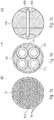
- FIG. 12 shows a full circle lighting unit 100 with a lighting surface 102 framed by the housing 104.
- the illumination surface 102 is characterized by a plurality of light-emitting elements 106, such.
- white LEDs or RGB LEDs are formed, which extend almost over the entire surface (ie, up to the edge 104) over the surface 102 regularly.
- Fig. 1b also shows a fully circular lighting element 110, which includes an outer housing 104 and a lighting surface 112. Within this illumination surface 112 four lighting bodies 116 are provided, which are arranged like a quadrant and fill the circular housing 104 or the circular illumination surface 112 from the inside.
- Fig. 1c shows a circular lighting element 120, which includes the housing 104 and a lighting surface 122. Within this illumination surface 122, a line-like illumination element 126 is provided that extends diagonally across the illumination surface 122.
- All lighting fixtures 100, 110 and 120 are similar in size and full circle. Consequently, the housings 104 are the same or comparable.
- these may have engaging means on their circular-arc-shaped outer side, by means of which the lighting fixture 100, 110 or 120 can be connected to further lighting fixtures.
- These engagement means may be, for example, rails, for example rails with a dovetail guide, so that telescoping is possible.
- other connectors would be z. B. conceivable with a groove and an additional clamping element.
- Fig. 1d shows a lighting fixture 130 which is semicircular, that forms a 180 ° -Kreissegment. This has an illumination surface 132, within which the illumination elements 106, over the entire surface, that are arranged to the edge.
- the lighting body 130 has a housing 134 that is essentially formed by a 180 ° half-circle, such as a connecting straight line. Both surfaces can serve as connecting surfaces.
- Fig. 1e shows a further lighting element 140, here in the form of a 90 ° -Kreissegments.
- the illumination element 140 has an illumination surface 142 that is filled with the illumination elements 106.
- the associated housing 144 has a 90 ° -Kreissegment Structure and two straight surfaces. All surfaces are provided for example by means of connecting means.
- the lighting elements 106, 116 and 126 can either be operated in color (RGB) or as white LEDs or as a combination (cf. Fig. 7 ) be formed.
- RGB color
- white LEDs it is advantageous that they can emit a high amount of light, so that for short-term control, z. B. in the range of 1 to 50 Hz, a stroboscopic effect can be achieved.
- these LEDs are designed to form a stroboscope.
- the light elements 106, 116 and 126 are synchronized within a lighting fixture 100, 110 and 120.
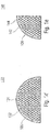
- Fig. 2a shows four circular arc-shaped lighting fixtures 200, which include a lighting surface 202 with a plurality of lighting elements 106.
- the lighting body 200 forms a 90 ° angle, namely in the form of a circular arc surface.
- the circular arc surface is enclosed by the housing 204.
- the housing 204 is thus defined by two circular arcs around a common center with different radii, each having the same angle. The ends of these two circular arcs are connected by straight lines.
- the circular arc surface 202 is designed as a 90 ° circular arc surface, this can also be designed differently, as shown for example by the dashed lines.
- the dashed lines divide the circular arc surface 202 into four equally sized circular arc surfaces, for example 22.5 °.
- both the straight side surfaces of the housing 204, and / or the curved side surfaces 104 are formed to be connected to other corresponding side surfaces.
- a connection of the straight side surfaces is in Fig. 2b illustrated.
- a lighting ring can be formed. This lighting ring is provided with the reference numeral 220.
- Fig. 3a shows a square or here rectangular lighting fixture 300 having a plurality of lighting elements 106 in the illumination surface 302.
- the illumination surface is enclosed by the housing 304.
- the housing 304 like the housing 204 explained in connection with the lighting elements 200, can have engagement sections on all four surfaces, so that a connection to further lighting elements can take place via the sides.
- Fig. 3b shows a further lighting body 310 having an illumination surface 314, wherein along the illumination surface 314, a lighting element 126 extends.
- shape of the lighting fixture 310 it should be noted that it is comparable to the lighting fixture 300 and therefore also has the same housing 304.
- Fig. 4a shows the combination of the lighting elements 200 and in particular of the lighting body assembly 220 with the lighting element 100.
- the lighting element 100 is framed by the four lighting fixtures 220, which are connected to each other via their longitudinal sides (straight sides) and in each case via its inner curved surface with the lighting fixture 100th or the outer surface of the lighting fixture 100 is connected. The connection is made via appropriate matching intervention means such.
- the circular lighting body 100 is enlarged in its circular area by the four circular surface segments 200.
- Fig. 4b shows the combination of the four circular lighting fixtures 200 with the lighting fixture 110, which as well as the lighting fixture 100 in Fig. 4a is disposed in the ring of the assembly 220.
- Fig. 4c shows the combination of the arrangement 220 comprising four circular arc surfaces 200 with the lighting fixture 120.
- Fig. 5a shows an assembly of a plurality of lighting fixtures 200, which are serpentine arranged in series. It should be noted that, just as in the arrangement 220, the lighting fixtures 200 are always connected to one another via their end faces, ie the straight faces. At one end of the queue / the luminous band two rectangular lighting elements 300 are also coupled via the front side. Furthermore, the light strip encloses the lighting body 100 in a 180 ° bend, which is coupled to the inside of the circular arc-shaped lighting elements 200 over an area of 180 °.
- Fig. 5b also shows a queue comprising a plurality of lighting elements 200 connected in correspondingly different directions (connection via the end faces).
- a lighting element 310 is coupled (also on the front side).
- the light strip in a 180 ° bend (consisting of two 90 ° -K Vietnamesebogen inhabit 200) encloses the lighting body 120, so that the connection again takes place on the inside of the circular arc surfaces with the outside of the full circle.
- the circular arc-like elements 200 can be connected via the end face with the rectangular elements 300 via the end face, the rectangular elements and the circular arc-like elements preferably have the same width.
- the circular or circular segment-shaped illumination elements have an outer radius which corresponds to the inner radius of the circular arc surface elements 200.
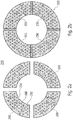
- Fig. 6a shows a further application of the modular system according to the above explanations.
- a rectangular arrangement is shown, consisting of 4x4 rectangular Lighting elements 340 consists.
- Each of these rectangular illumination elements 340 has a plurality of regularly arranged illumination elements 346 on the illumination surface 342.
- These lighting elements 346 are particularly designed according to an additional embodiment, namely have a white LED in the middle and around a variety of arranged around it, for. B. circularly arranged RGB LEDs.
- 16 RGB LEDs are conceivable.
- this is realized by 25 white LEDs (5x5) with 25x16 RGB LEDs in a circle around the 25 white LEDs.
- the reference point 348 marks the connection point in the context of the illumination elements 340. It should be noted that with the 4x4 matrix shown here, it is possible to cover, for example, an area of 1x1 m from the 4x4 lighting bodies 340.
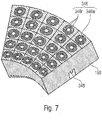
- Fig. 6b shows 12 serpentine-shaped circular arc-shaped lighting fixture 160. These include here each a 45 ° angle and include on the illumination surface 166 a variety, such. B. 25 lighting elements 346, in turn, individually centrally arranged white LEDs and circular outside arranged around RGB LEDs, z. B. 16 per white LEDs may include.
- Fig. 6c shows the combination of the lighting fixtures 340 with the lighting fixtures 160.
- the lighting fixtures 340 are adapted to be connected to a further lighting fixture via each of the four sides.
- the lighting fixtures 340 are arranged such that a letter D is formed by six lighting fixtures 340 and four lighting fixtures 160.
- the external dimensions are approx. 1x1 m.
- a lighting ring can be formed with a diameter of 1 m.
- the lighting elements 160 are each connected to one another via the front side.
- each light fixture different LEDs such.
- the areally arranged LEDs or other lighting elements such.
- B. linear lighting elements (in longitudinal or diagonal orientation) can be used. These LEDs can also be designed or activated for continuous illumination or for stroboscopic lighting.
- the above-described mold space for the kit which preferably comprises three, but at least two different forms is not limited by the above embodiments, but that also different other forms (quadrant, semicircular or polygonal shape) for Use can come.
- the mechanical connection is not limited by the above-discussed rail connector.
- connectors can be used.
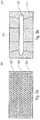
- Fig. 7 shows the lighting fixture 160.
- the (25) lighting elements 346 are arranged regularly, for example every 5 or more on a line, always two lines forming an angle.
- each illumination element 346 may be formed by a plurality of individual subelements, namely a white illumination subelement 346 w (white LED) with a plurality, eg 10 or 10 further (colored) illumination subelements 346r (RGB LEDs) on top of it.
- These sub-elements 346r may be annular (one ring, two rings, etc.) or angularly arranged around the sub-element 346w.
Landscapes
- Engineering & Computer Science (AREA)
- General Engineering & Computer Science (AREA)
- Non-Portable Lighting Devices Or Systems Thereof (AREA)
Applications Claiming Priority (1)
| Application Number | Priority Date | Filing Date | Title |
|---|---|---|---|
| DE102018205302.2A DE102018205302A1 (de) | 2018-04-09 | 2018-04-09 | Beleuchtungs-Baukastensystem |
Publications (1)
| Publication Number | Publication Date |
|---|---|
| EP3553365A1 true EP3553365A1 (fr) | 2019-10-16 |
Family
ID=66102885
Family Applications (1)
| Application Number | Title | Priority Date | Filing Date |
|---|---|---|---|
| EP19167984.4A Withdrawn EP3553365A1 (fr) | 2018-04-09 | 2019-04-08 | Système modulaire d'éclairage |
Country Status (2)
| Country | Link |
|---|---|
| EP (1) | EP3553365A1 (fr) |
| DE (1) | DE102018205302A1 (fr) |
Citations (4)
| Publication number | Priority date | Publication date | Assignee | Title |
|---|---|---|---|---|
| FR2873785A1 (fr) * | 2004-07-30 | 2006-02-03 | Chromlech Sarl | Dispositif et module d'eclairage scenique integres et controlables |
| US20160304215A1 (en) * | 2015-04-16 | 2016-10-20 | Hughey & Phillips, Llc | Obstruction Lighting System Configured to Emit Visible and Infrared Light |
| US20170227180A1 (en) * | 2016-02-05 | 2017-08-10 | Timothy Lee Anderson | Laser Based Visual Effect Device and System |
| DE202017005050U1 (de) * | 2017-09-29 | 2017-11-16 | Glp German Light Products Gmbh | Beleuchtungsvorrichtung |
Family Cites Families (5)
| Publication number | Priority date | Publication date | Assignee | Title |
|---|---|---|---|---|
| IT1315709B1 (it) * | 2000-06-09 | 2003-03-18 | Omnilux Srl | Elementi illuminanti modulari con diodi led. |
| US7202613B2 (en) * | 2001-05-30 | 2007-04-10 | Color Kinetics Incorporated | Controlled lighting methods and apparatus |
| CN101545614B (zh) * | 2008-03-26 | 2012-05-23 | 富准精密工业(深圳)有限公司 | 发光二极管灯具 |
| DE102010027579A1 (de) * | 2010-07-19 | 2012-01-19 | Osram Opto Semiconductors Gmbh | Leuchtdiodenmodul und Leuchte |
| DE112015003293T5 (de) * | 2014-07-15 | 2017-06-29 | Citizen Electronics Co., Ltd. | Licht emittierende Vorrichtung |
-
2018
- 2018-04-09 DE DE102018205302.2A patent/DE102018205302A1/de active Pending
-
2019
- 2019-04-08 EP EP19167984.4A patent/EP3553365A1/fr not_active Withdrawn
Patent Citations (4)
| Publication number | Priority date | Publication date | Assignee | Title |
|---|---|---|---|---|
| FR2873785A1 (fr) * | 2004-07-30 | 2006-02-03 | Chromlech Sarl | Dispositif et module d'eclairage scenique integres et controlables |
| US20160304215A1 (en) * | 2015-04-16 | 2016-10-20 | Hughey & Phillips, Llc | Obstruction Lighting System Configured to Emit Visible and Infrared Light |
| US20170227180A1 (en) * | 2016-02-05 | 2017-08-10 | Timothy Lee Anderson | Laser Based Visual Effect Device and System |
| DE202017005050U1 (de) * | 2017-09-29 | 2017-11-16 | Glp German Light Products Gmbh | Beleuchtungsvorrichtung |
Also Published As
| Publication number | Publication date |
|---|---|
| DE102018205302A1 (de) | 2019-10-10 |
Similar Documents
| Publication | Publication Date | Title |
|---|---|---|
| EP2729840B1 (fr) | Élément influant sur la lumière, servant à influer sur l'émission de lumière de sources lumineuses sensiblement en forme de points | |
| EP3014169A1 (fr) | Luminaire destiné à être utilisé dans un système de rampe d'éclairage ainsi que système de rampe d'éclairage | |
| DE202007005495U1 (de) | Warnleuchtsäule | |
| EP1347233A2 (fr) | Colonne de signalisation | |
| WO2012159744A2 (fr) | Appareil d'éclairage, en particulier appareil d'éclairage public à diodes électroluminescentes | |
| EP2824380B1 (fr) | Éclairage | |
| DE102009017162B4 (de) | Modulsystem zur Schaffung einer Leuchte | |
| DE102010042193A1 (de) | LED-Leuchte mit gebogenem Lichtabgebebereich | |
| EP3426975B1 (fr) | Dispositif d'éclairage pour éclairage uniforme | |
| DE202018100238U1 (de) | Modular erweiterbare und formveränderliche Leuchte | |
| EP3553365A1 (fr) | Système modulaire d'éclairage | |
| EP3203141A1 (fr) | Optique d'éclairage, système d'optique d'éclairage et éclairage comprenant une optique d'éclairage | |
| EP3686480A1 (fr) | Agencement d'émission de lumière ayant des caractéristiques de faisceau lumineux modifiables | |
| WO2019175389A1 (fr) | Projecteur pourvu de groupes de del | |
| DE102011110580A1 (de) | Leuchte, insbesondere Straßenleuchte mit LEDs | |
| EP2518389B1 (fr) | Élément optique longitudinal et agencement d'émission de lumière avec un élément optique | |
| DE102017124853A1 (de) | Optisches System für eine LED-Leuchte | |
| DE102017130023B4 (de) | Leuchte | |
| EP2833048A1 (fr) | Éclairage doté d'un élément de support et d'un module de moyen d'éclairage amovible | |
| DE102017129779A1 (de) | Lightengine für ein Leuchtmittel und Leuchtmittel | |
| DE102015225329A1 (de) | Lampe mit rohrförmigem Kolben | |
| EP2994690B1 (fr) | Luminaire équipé d'un boîtier comportant plusieurs orifices de rayonnement de lumière | |
| EP2833050B1 (fr) | Lampe suspendue dotée d'une source lumineuse destinée à produire un éclairage indirect | |
| DE9017407U1 (de) | Leuchtenelementanordnung mit mehreren Leuchtenelementen | |
| EP2218961A1 (fr) | Elément d'éclairage, élément de connexion et système composé d'un élément d'éclairage et d'un élément de connexion |
Legal Events
| Date | Code | Title | Description |
|---|---|---|---|
| PUAI | Public reference made under article 153(3) epc to a published international application that has entered the european phase |
Free format text: ORIGINAL CODE: 0009012 |
|
| AK | Designated contracting states |
Kind code of ref document: A1 Designated state(s): AL AT BE BG CH CY CZ DE DK EE ES FI FR GB GR HR HU IE IS IT LI LT LU LV MC MK MT NL NO PL PT RO RS SE SI SK SM TR |
|
| AX | Request for extension of the european patent |
Extension state: BA ME |
|
| STAA | Information on the status of an ep patent application or granted ep patent |
Free format text: STATUS: THE APPLICATION IS DEEMED TO BE WITHDRAWN |
|
| 18D | Application deemed to be withdrawn |
Effective date: 20200603 |