EP3553310A1 - Windmill drive system and windmill - Google Patents
Windmill drive system and windmill Download PDFInfo
- Publication number
- EP3553310A1 EP3553310A1 EP17878150.6A EP17878150A EP3553310A1 EP 3553310 A1 EP3553310 A1 EP 3553310A1 EP 17878150 A EP17878150 A EP 17878150A EP 3553310 A1 EP3553310 A1 EP 3553310A1
- Authority
- EP
- European Patent Office
- Prior art keywords
- driving devices
- wind turbine
- load
- drive
- ring gear
- Prior art date
- Legal status (The legal status is an assumption and is not a legal conclusion. Google has not performed a legal analysis and makes no representation as to the accuracy of the status listed.)
- Granted
Links
- 238000001514 detection method Methods 0.000 claims abstract description 73
- 230000002159 abnormal effect Effects 0.000 claims abstract description 56
- 238000012544 monitoring process Methods 0.000 claims abstract description 13
- 230000007246 mechanism Effects 0.000 claims description 76
- 238000012360 testing method Methods 0.000 claims description 75
- 238000000034 method Methods 0.000 claims description 33
- 230000008569 process Effects 0.000 claims description 30
- 230000005856 abnormality Effects 0.000 description 47
- 238000011946 reduction process Methods 0.000 description 19
- 238000010248 power generation Methods 0.000 description 14
- 230000007257 malfunction Effects 0.000 description 9
- 230000008859 change Effects 0.000 description 8
- 238000006073 displacement reaction Methods 0.000 description 8
- 230000009467 reduction Effects 0.000 description 6
- 230000008439 repair process Effects 0.000 description 5
- 230000005540 biological transmission Effects 0.000 description 3
- 230000007613 environmental effect Effects 0.000 description 3
- 238000009434 installation Methods 0.000 description 3
- 230000002093 peripheral effect Effects 0.000 description 3
- 230000000717 retained effect Effects 0.000 description 3
- 238000010586 diagram Methods 0.000 description 2
- 238000011835 investigation Methods 0.000 description 2
- 238000005259 measurement Methods 0.000 description 2
- 230000004048 modification Effects 0.000 description 2
- 238000012986 modification Methods 0.000 description 2
- 238000003491 array Methods 0.000 description 1
- 239000000470 constituent Substances 0.000 description 1
- 230000008878 coupling Effects 0.000 description 1
- 238000010168 coupling process Methods 0.000 description 1
- 238000005859 coupling reaction Methods 0.000 description 1
- 230000005611 electricity Effects 0.000 description 1
- 230000002349 favourable effect Effects 0.000 description 1
- 230000001360 synchronised effect Effects 0.000 description 1
- 238000013024 troubleshooting Methods 0.000 description 1
Images


Classifications
-
- F—MECHANICAL ENGINEERING; LIGHTING; HEATING; WEAPONS; BLASTING
- F03—MACHINES OR ENGINES FOR LIQUIDS; WIND, SPRING, OR WEIGHT MOTORS; PRODUCING MECHANICAL POWER OR A REACTIVE PROPULSIVE THRUST, NOT OTHERWISE PROVIDED FOR
- F03D—WIND MOTORS
- F03D7/00—Controlling wind motors
- F03D7/02—Controlling wind motors the wind motors having rotation axis substantially parallel to the air flow entering the rotor
- F03D7/0204—Controlling wind motors the wind motors having rotation axis substantially parallel to the air flow entering the rotor for orientation in relation to wind direction
-
- F—MECHANICAL ENGINEERING; LIGHTING; HEATING; WEAPONS; BLASTING
- F03—MACHINES OR ENGINES FOR LIQUIDS; WIND, SPRING, OR WEIGHT MOTORS; PRODUCING MECHANICAL POWER OR A REACTIVE PROPULSIVE THRUST, NOT OTHERWISE PROVIDED FOR
- F03D—WIND MOTORS
- F03D7/00—Controlling wind motors
- F03D7/02—Controlling wind motors the wind motors having rotation axis substantially parallel to the air flow entering the rotor
- F03D7/0244—Controlling wind motors the wind motors having rotation axis substantially parallel to the air flow entering the rotor for braking
- F03D7/0248—Controlling wind motors the wind motors having rotation axis substantially parallel to the air flow entering the rotor for braking by mechanical means acting on the power train
-
- F—MECHANICAL ENGINEERING; LIGHTING; HEATING; WEAPONS; BLASTING
- F03—MACHINES OR ENGINES FOR LIQUIDS; WIND, SPRING, OR WEIGHT MOTORS; PRODUCING MECHANICAL POWER OR A REACTIVE PROPULSIVE THRUST, NOT OTHERWISE PROVIDED FOR
- F03D—WIND MOTORS
- F03D15/00—Transmission of mechanical power
-
- F—MECHANICAL ENGINEERING; LIGHTING; HEATING; WEAPONS; BLASTING
- F03—MACHINES OR ENGINES FOR LIQUIDS; WIND, SPRING, OR WEIGHT MOTORS; PRODUCING MECHANICAL POWER OR A REACTIVE PROPULSIVE THRUST, NOT OTHERWISE PROVIDED FOR
- F03D—WIND MOTORS
- F03D15/00—Transmission of mechanical power
- F03D15/10—Transmission of mechanical power using gearing not limited to rotary motion, e.g. with oscillating or reciprocating members
-
- F—MECHANICAL ENGINEERING; LIGHTING; HEATING; WEAPONS; BLASTING
- F03—MACHINES OR ENGINES FOR LIQUIDS; WIND, SPRING, OR WEIGHT MOTORS; PRODUCING MECHANICAL POWER OR A REACTIVE PROPULSIVE THRUST, NOT OTHERWISE PROVIDED FOR
- F03D—WIND MOTORS
- F03D17/00—Monitoring or testing of wind motors, e.g. diagnostics
-
- F—MECHANICAL ENGINEERING; LIGHTING; HEATING; WEAPONS; BLASTING
- F03—MACHINES OR ENGINES FOR LIQUIDS; WIND, SPRING, OR WEIGHT MOTORS; PRODUCING MECHANICAL POWER OR A REACTIVE PROPULSIVE THRUST, NOT OTHERWISE PROVIDED FOR
- F03D—WIND MOTORS
- F03D80/00—Details, components or accessories not provided for in groups F03D1/00 - F03D17/00
- F03D80/50—Maintenance or repair
- F03D80/55—Cleaning
-
- F—MECHANICAL ENGINEERING; LIGHTING; HEATING; WEAPONS; BLASTING
- F16—ENGINEERING ELEMENTS AND UNITS; GENERAL MEASURES FOR PRODUCING AND MAINTAINING EFFECTIVE FUNCTIONING OF MACHINES OR INSTALLATIONS; THERMAL INSULATION IN GENERAL
- F16H—GEARING
- F16H1/00—Toothed gearings for conveying rotary motion
- F16H1/02—Toothed gearings for conveying rotary motion without gears having orbital motion
- F16H1/04—Toothed gearings for conveying rotary motion without gears having orbital motion involving only two intermeshing members
- F16H1/06—Toothed gearings for conveying rotary motion without gears having orbital motion involving only two intermeshing members with parallel axes
- F16H1/10—Toothed gearings for conveying rotary motion without gears having orbital motion involving only two intermeshing members with parallel axes one of the members being internally toothed
-
- F—MECHANICAL ENGINEERING; LIGHTING; HEATING; WEAPONS; BLASTING
- F16—ENGINEERING ELEMENTS AND UNITS; GENERAL MEASURES FOR PRODUCING AND MAINTAINING EFFECTIVE FUNCTIONING OF MACHINES OR INSTALLATIONS; THERMAL INSULATION IN GENERAL
- F16H—GEARING
- F16H1/00—Toothed gearings for conveying rotary motion
- F16H1/02—Toothed gearings for conveying rotary motion without gears having orbital motion
- F16H1/20—Toothed gearings for conveying rotary motion without gears having orbital motion involving more than two intermeshing members
-
- Y—GENERAL TAGGING OF NEW TECHNOLOGICAL DEVELOPMENTS; GENERAL TAGGING OF CROSS-SECTIONAL TECHNOLOGIES SPANNING OVER SEVERAL SECTIONS OF THE IPC; TECHNICAL SUBJECTS COVERED BY FORMER USPC CROSS-REFERENCE ART COLLECTIONS [XRACs] AND DIGESTS
- Y02—TECHNOLOGIES OR APPLICATIONS FOR MITIGATION OR ADAPTATION AGAINST CLIMATE CHANGE
- Y02E—REDUCTION OF GREENHOUSE GAS [GHG] EMISSIONS, RELATED TO ENERGY GENERATION, TRANSMISSION OR DISTRIBUTION
- Y02E10/00—Energy generation through renewable energy sources
- Y02E10/70—Wind energy
- Y02E10/72—Wind turbines with rotation axis in wind direction
Definitions
- the present invention relates to a wind turbine drive system used for a movable section of a wind turbine, and the wind turbine.
- a wind turbine used as a wind power generator has been known as disclosed in, for example, Japanese Patent Application Publication 2015-140777 .
- the wind turbine includes a nacelle turnably installed at the top of a tower and in which a generator and the like are disposed, and a blade installed rotatably relative to a rotor (hub, main shaft) attached to the nacelle.
- the wind turbine has a yaw driving device or a pitch driving device that rotates one structure relative to the other structure at the movable section of the wind turbine.
- the yaw driving device turns the nacelle, which is the one structure, relative to the tower, which is the other structure, depending on the wind direction.
- the pitch driving device adjusts a pitch angle of the blade by turning the shaft of the blade, which is the one structure, relative to the rotor in the nacelle, which is the other structure.
- a plurality of driving devices are provided in a single movable section of the wind turbine.
- a large force may be generated at a meshing portion between a drive gear, which is an output portion of the driving device, and a ring gear meshing with the drive gear.
- the plurality of driving devices may rotate respective drive gears by different amounts until the teeth of the drive gears contact with the teeth of the ring gear. Accordingly, in starting operation of a plurality of driving devices, an excessive load may be generated at a meshing portion of each driving device at which the amount of rotation of the drive gear until the teeth of the drive gear contact with the teeth of the ring gear is the smallest.
- the driving device or ring gear When the force generated in the meshing portion becomes large, the driving device or ring gear may be broken. If the driving device is broken, it is necessary to replace part or all of the driving device. If the ring gear or a structure around the ring gear is broken, a large-scale repair work will be required, and the operation of the wind turbine has to be stopped for a long period of time. To address such faults, it is effective, when a large load is generated in the meshing portion, to first stop power generation of the wind turbine and investigate the cause.
- the present invention addresses the above drawbacks and one object thereof is to improve the control upon detecting an excessive load in the movable section of a wind turbine to raise the capacity utilization of the wind turbine.
- the present invention is aimed at appropriate handling of an abnormal load generated by temporary causes thereby to raise the capacity utilization of the wind turbine.
- a wind turbine drive system of the present invention includes: a plurality of driving devices installed in one structure at a movable section of a wind turbine, each of the plurality of driving devices including a drive gear meshing with a ring gear installed in another structure at the movable section of the wind turbine; a state quantity detection unit for monitoring, for each of the plurality of driving devices, a load generated between the drive gear of each of the plurality of driving devices and the ring gear; and a control unit for performing control for reducing the load when the state quantity detection unit detects an abnormal load
- the wind turbine drive system of the present invention may be configured such that when the state quantity detection unit detects an abnormal load, the control unit controls the plurality of driving devices so as to stop output from the drive gear of each of all the driving devices included in the plurality of driving devices to the ring gear.
- the wind turbine drive system of the present invention may be configured such that each of the plurality of driving devices includes a brake mechanism that brakes rotation transmitted to the drive gear or rotation output from the drive gear; and when the state quantity detection unit detects an abnormal load, the control unit controls the brake mechanism of each of the plurality of driving devices such that the brake mechanism brakes rotation.
- the wind turbine drive system of the present invention may be configured such that when the state quantity detection unit detects an abnormal load, the control unit adjusts a pitch angle of a blade included in the wind turbine.
- the wind turbine drive system of the present invention may be configured such that when the state quantity detection unit detects an abnormal load, the control unit controls the plurality of driving devices so as to stop output from the drive gear of each of all the driving devices included in the plurality of driving devices to the ring gear, and then, when the abnormal load is not eliminated, adjusts a pitch angle of a blade included in the wind turbine.
- the wind turbine drive system of the present invention may be configured such that when the state quantity detection unit detects an abnormal load, the control unit first performs a process for reducing the bad and then controls either simultaneously or sequentially the plurality of driving devices for test operation.
- the wind turbine drive system of the present invention may be configured such that the control unit controls the plurality of driving devices for the test operation so as to output a drive force from the drive gear of each of the plurality of driving devices to the ring gear at a lower torque than in normal operation.
- the wind turbine drive system of the present invention may be configured such that the control unit controls the plurality of driving devices so as to perform the test operation simultaneously and checks whether the one structure and the other structure operated relative to each other.
- the wind turbine drive system of the present invention may be configured such that the control unit controls the plurality of driving devices so as to perform the test operation sequentially and checks whether the drive gear of each of the plurality of driving devices operated by a predetermined amount that is less than one pitch of teeth of the drive gear.
- the wind turbine drive system of the present invention may be configured such that each of the plurality of driving devices includes a brake mechanism that brakes rotation transmitted to the drive gear or rotation output from the drive gear; and the control unit controls the plurality of driving devices such that the brake mechanism of each of the plurality of driving devices operates for test operation.
- the wind turbine drive system of the present invention may be configured such that the control unit controls the plurality of driving devices for the test operation such that the brake mechanism of each of the plurality of driving devices operates first and then the drive force is output from the drive gear of each of the plurality of driving devices to the ring gear.
- a wind turbine according to the present invention includes any one of the above wind turbine drive systems according to the present invention.
- the present invention improves the control upon detecting an excessive load in the movable section of a wind turbine, thereby to raise the capacity utilization of the wind turbine.
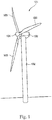
- Fig. 1 is a perspective view of a wind turbine 101.
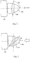
- Figs. 2 and 3 are side views of a part of the wind turbine.
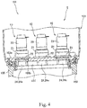
- Fig. 4 is a sectional view showing part of a tower 102 and a nacelle 103.
- driving devices 10 are shown with an outer appearance thereof instead of a cross-section thereof.
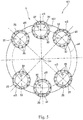
- Fig. 5 is a plan view showing an arrangement of the driving devices 10 in a movable section shown in Fig. 4 .
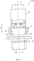
- Fig. 6 is a side view of one of the driving devices 10, part of which is shown in longitudinal-section.
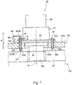
- Fig. 7 is a view showing an installation portion of the driving device 10, part of which is shown in longitudinal-section.
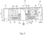
- Fig. 8 is a view showing a brake mechanism of the driving device 10 in longitudinal-section.
- the driving device 10 is capable of driving the nacelle 103 installed so as to be rotatable with respect to the tower 102 of the wind turbine 101 or driving a blade 105 installed so as to be swingable in a pitch direction with respect to a rotor 104 mounted to the nacelle 103. That is, the driving device 10 can be used as a yaw driving device for carrying out yaw driving so as to cause the nacelle 103 to rotate with respect to the tower 102 and also as a pitch driving device for carrying out pitch driving so as to cause a shaft portion of the blade 105 to rotate with respect to the rotor 104. While the following describes an example in which the driving device 10 is used as a yaw driving device, the present invention is applicable also to a case where the driving device 10 is used as a pitch driving device.
- the wind turbine 101 includes the tower 102, the nacelle 103, the rotor 104, the blade 105, and so on.
- the tower 102 extends upward in a vertical direction from the ground
- the nacelle 103 is installed on a top portion of the tower 102 so as to be rotatable relative thereto. Rotation of the nacelle 103 with respect to the tower 102 is yaw rotation about a longitudinal direction of the tower 102 as a rotation center.
- the nacelle 103 is driven by a plurality of driving devices 10 to rotate with respect to the tower 102.
- the nacelle 103 contains devices installed therein for wind power generation, such as a power transmission shaft, an electric power generator connected to the power transmission shaft.
- the rotor 104 is connected to the power transmission shaft and is rotatable with respect to the nacelle 103.
- a plurality of blades 105 (three blades 105 in the example shown in Fig. 1 ) extend from the rotor 104 in radial directions about a rotation axis of the rotor 104 that rotates with respect to the nacelle 103.
- the plurality of blades 105 are arranged at equal angular intervals.
- the blades 105 are each rotatable in the pitch direction. More specifically, the blades 105 are each rotatable about a longitudinal direction thereof with respect to the rotor 104.
- a connection point between the blades 105 and the rotor 104 is configured as a movable section so that the blades 105 and the rotor 104 are rotatable relative to each other.
- the blades 105 are driven to rotate by a driving device provided as a pitch driving device.
- the driving device as the pitch driving device may be configured similarly to an after-mentioned driving device 10 as a yaw driving device.
- the pitch angle ⁇ p of the blade 105 is adjusted in accordance with the wind velocity.
- the pitch angle ⁇ p is set to a large value, as shown in Fig. 2 , such that the blade 105 receives the wind power positively.
- the pitch angle ⁇ p is set to a small value, as shown in Fig. 3 , to prevent the rotor 104 from rotating at an excessively high speed.
- the orientation of the blade 105 is set to a position of feathering with the pitch angle ⁇ p of approximately 0°. In the examples shown in Figs.
- the pitch angle ⁇ p is defined as an angle contained between the rotation axis of the rotor and the surface of the blade 105. As the pitch angle ⁇ p is larger, the blade 105 receives the wind power more efficiently. On the other hand, when the pitch angle ⁇ p is smaller, the wind power received by the blade 105 is reduced Therefore, the wind power received by the blade 105 in the position of feathering is the smallest.
- the position of the nacelle 103 is set such that the rotor 104 faces the wind straight. More specifically, in operation of the wind turbine 101, the position of the nacelle 103 is set such that the rotor 104 faces windward and the rotation axis of the rotor 104 is oriented along the wind direction.
- the wind power received by the blade 105 acts as an external force to turn the nacelle 103 by 180°. More specifically, the wind power acts on the movable section of the nacelle 103 and the tower 102 such that the rotor 104 faces leeward and the rotation axis of the rotor 104 is oriented along the wind direction. Accordingly, the force acting on the movable section can be reduced as the pitch angle ⁇ p of the blade 105 is smaller.
- the nacelle 103 is installed on the top of the tower 102 so as to be rotatable relative thereto via a bearing 106 interposed between a bottom portion 103a of the nacelle 103 and the tower 102.
- a ring gear 107 having internal teeth formed on an inner periphery thereof is fixed to the top portion of the tower 102.
- the ring gear 107 may have external teeth provided on an outer periphery thereof, instead of the internal teeth provided on the inner periphery thereof. In the drawings, the teeth of the ring gear 107 are not shown.
- the plurality of driving devices 10 are provided in the nacelle 103 (a first structure), not in the tower 102 (a second structure), both configured to rotate relative to each other.
- Each of the driving devices 10 includes a drive gear 24a meshing with the teeth of the ring gear 10 provided in the tower 102.
- each of the driving devices 10 is provided with an electric motor 23 and a speed reducing unit 25.
- the electric motor 23 includes a motor drive unit and a motor brake unit (described later), and the speed reducing unit 25 receives power transmitted from the electric motor 23 (particularly, the motor drive unit).
- the motor drive unit outputs a drive force (rotational power), and the motor brake unit brakes the motor drive unit to reduce the drive force (rotational power) outputted from the motor drive unit.
- braking used herein is to be broadly construed, and a definition thereof embraces retaining a stopped state of an object that has been stopped and stopping a moving object.
- the driving devices 10 By driving of the driving devices 10 thus configured, it is possible to cause the nacelle 103 (the first structure) as one side of a movable section of the wind turbine 101 to rotate with respect to the tower 102 (the second structure) as the other side of the movable section of the wind turbine 101.
- the plurality of driving devices 10 included in the wind turbine are operated in a synchronized manner and thus provide drive power of a magnitude sufficient to cause the nacelle 103, which is a heavy object, to properly swivel with respect to the tower 102.
- the driving devices 10 operate based on a control signal sent from a controller 110 (a control unit, see Fig. 9 ) (described later) to the electric motor 23 (the motor drive unit and the motor brake unit).
- the plurality of driving devices 10 collectively constitute a driving device unit. Further, the driving device unit, the controller 110, and a state quantity detecting portion 80 (described later) constitute the wind turbine drive system 5.
- the ring gear 107 is formed in a circumferential shape and has a center axis Cm.
- the nacelle 103 rotates about the center axis Cm of the ring gear 107.
- the center axis Cm of the ring gear 107 corresponds to the longitudinal direction of the tower 102.
- a direction parallel to the center axis Cm of the ring gear 107 is simply referred to also as an "axial direction dl"
- each driving device group includes three driving devices 10.
- six driving devices 10 included in the pair of driving device groups constitute the driving device unit 9
- Bodies 20 of the driving devices are arranged along a circumference cl1 (see Fig. 5 ) about the center axis Cm of the ring gear 107.
- the three driving devices 10 included in each driving device group are arranged at given intervals along the circumference cl1.
- Each of the driving devices 10 has a driving device body 20 fixed to the nacelle 103. As shown in Fig. 7 , each of the driving devices 10 is fixed to the nacelle 103 (the first structure) via a fastener 30 disposed so as to extend through a through hole 22a formed through a flange 22 of the driving device body 20. Moreover, each of the driving devices 10 includes a load sensor 40 (see Fig. 7 ) for finding any abnormality in the driving device body 20. As will be described later, the load sensor 40 can indirectly detect a load (stress) between the drive gear 24a of each of the driving devices 10 and the ring gear 107.
- the load sensor 40 is mounted to a location on which no other disturbance than a load between the drive gear 24a and the ring gear 107 acts or is likely to act.
- the load sensor 40 serves as a sensor that measures a change in the state of the fastener 30.
- the fastener 30 changes its state in conjunction with a load (stress) produced between the drive gear 24a of each of the driving devices 10 and the ring gear 107.
- the load sensor 40 shown is disposed to contact with the fastener 30, and it is also possible that the load sensor 40 is disposed on the case to monitor a change in the state of the case.
- the driving device body 20 is provided with an output shaft 24 having the drive gear 24a that meshes with the ring gear 107, the case 21 rotatably retaining the output shaft 24, and the electric motor 23 fixed to the case 21. Furthermore, the driving device body 20 is provided further with the speed reducing unit 25 housed in the case 21 and connecting the electric motor 23 to the output shaft 24. The speed reducing unit 25 decelerates an input (rotational power) from the electric motor 23 while increasing a torque thereof and transmits the input to the output shaft 24.
- the speed reducing unit 25 can typically adopt an eccentric oscillating gear-type speed reducing mechanism, a planetary gear-type speed reducing mechanism, or a speed reducing mechanism combining the eccentric oscillating gear-type and the planetary gear-type.
- An end portion of the output shaft 24 distal from the speed reducing unit 25 extends out from the case 21, and the drive gear 24a is formed at this extending-out portion of the output shaft 24.
- the output shaft 24 penetrates through a through hole 103b formed through the bottom portion 103a of the nacelle 103 and meshes with the ring gear 107.
- the drive gear 24a has a shape adapted to the ring gear 107.
- the drive gear 24a can be formed as a pinion gear having external teeth configured to mesh with the internal teeth of the ring gear 107.
- Each of the driving devices 10 has a longitudinal axis corresponding to a rotation axis Cr of the output shaft 24. In a state where each of the driving devices 10 is fixed to the nacelle 103, the rotation axis Cr of the output shaft 24 is parallel to an axial direction dl of the wind turbine 101.
- the case 21 is formed in a cylindrical shape as shown in Fig. 6 and is disposed so that a longitudinal axis thereof is positioned in the rotation axis Cr as shown in Fig. 7 .
- the case 21 is open at both ends thereof along the rotation axis Cr.
- the drive gear 24a of the output shaft 24 is exposed from an opening of the case 21 near the tower 102.
- the electric motor 23 is mounted to an opening of the case 21 on an opposite side to the tower 102.
- the case 21 includes the flange 22.
- the flange 22 of this example is formed in an annular shape and extends along a circumference cl3 about the rotation axis Cr of the output shaft 24.
- the through hole 22a is formed through the flange 22 so as to extend in the axial direction dl.
- a multitude of through holes 22a are formed on a circumference cl3 about the rotation axis Cr of the output shaft 24. In an example shown, twelve through holes 22a are formed
- each of the fasteners 30 penetrates through the flange 20 by extending through the through holes 22a formed through the flange 22 of the driving device body 20.
- each of the fasteners 30 includes a bolt 30a and a nut 30b.
- the bolt 30a penetrates through the flange 22 of the driving device body 20 and the bottom portion 103a of the nacelle 103.
- the nut 30b is screwed with the bolt 30a in a direction from the tower 102.
- the fastener 30 formed of a combination of the bolt 30a and the nut 30b is provided for each of the through holes 22a of the driving device body 20.
- the driving device bodies 20 are mounted to the nacelle 103 at twelve locations with twelve fasteners 30.
- the fastener 30 is not limited to the illustrated example.
- the fastener 30 may be configured such that, instead of using the nut 30b, a female screw with which a male screw of the bolt 30a can be screwed is formed along a through hole of the nacelle 103.
- the fastener 30 is formed of the bolt 30a, and the male screw of the bolt 30a meshes with the female screw in the through hole of the nacelle 103, thus making it possible to fix the driving device body 20 to the nacelle 103.
- the load sensor 40 measures a change in state of the fastener 30 and thus can directly or indirectly measure an amount of a force acting on the fastener 30.
- the load sensor 40 may be formed of a known sensor for measuring one or more of a load applied to the fastener 30, a displacement of the fastener 30 with respect to the nacelle 103, and a relative position of the fastener 30 to the nacelle 103.
- an axial force sensor is used as the sensor 40, and thus it is possible to measure a load (an axial force) toward a particular direction applied to the fastener 30.
- a magnetic sensor or a photoelectric sensor may be used as the sensor 40 to measure a position and a displacement of the fastener 30 in a non-contact manner.
- the fastener 30 changes its state in conjunction with a load (stress) produced between the drive gear 24a of each of the driving devices 10 and the ring gear 107. Therefore, by monitoring a change in the state of fastener 30 with the load sensor 40, it is possible to evaluate the magnitude of the load (stress) produced in the meshing portion between the drive gear 24a and the ring gear 107.
- the load sensor 40 is fixedly retained with a jig 49 to the nacelle 103, which is one side of the movable section.
- the axial force sensor constituting the load sensor 40 contacts with a head portion of the bolt 30a as a component of the fastener 30.
- the load sensor 40 may contact with a distal end portion of the bolt 30a on an opposite side to the head portion or may contact with the nut 30b.
- the load sensor 40 may detect a load applied to a fastening bolt fastening the nacelle 103 to the case 21.
- the load sensor 40 is electrically connected to the controller 110 (see Fig. 9 ) (described later), and an electric signal related to a result of measurement outputted from the load sensor 40 is transmitted to the controller 110.
- the controller 110 monitors the electric signal outputted from the sensor 40, and thus it is possible to grasp a change in load applied to the fastener 30 and a displacement of the fastener 30. Based on a result of measurement by the load sensor 40, the controller 110 can control the various types of constituent elements of the wind turbine 101, such as the driving devices 10.
- the electric motor 23 includes a motor drive unit 48 and a motor brake unit 50.
- Fig. 8 is a view schematically showing a partial longitudinal section of the electric motor 23.
- the motor brake unit 50 is a brake mechanism that brakes a rotational motion conveyed to the drive gear 24a.
- the driving device body 20 may include various forms of brake mechanism that brakes the rotational motion conveyed to the drive gear 24a or the rotational motion output from the drive gear 24a.
- the electric motor 23 provided with a motor drive unit 48 and a motor brake unit 50 is provided in each of the driving devices 10, and one motor brake unit 50 is mounted to each motor drive unit 48.
- the motor drive unit 48 can be formed of any device capable of controlling the number of rotations of a drive shaft 48a based on a command from the controller 110 (see Fig. 9 ).
- the motor brake unit 50 shown includes a mechanism as an electromagnetic brake for braking rotation of the drive shaft 48a of the motor drive unit 48 or releasing the drive shaft 48a from being braked, based on a command from the controller 110 (see Fig. 9 ).
- the motor brake unit 50 of this example is mounted to an end portion of a cover 72 of the motor drive unit 48 on an opposite side to the speed reducing unit 25 and includes a housing 51, a friction plate 56, an armature 57, an elastic member 55, an electromagnet 53, a first friction plate connecting portion 77, and so on.
- the housing 51 is a structure that houses the friction plate 56, the armature 57, the elastic member 55, the electromagnet 53, the first friction plate connecting portion 77, and so on and is fixed to the cover 72 of the motor drive unit 48.
- the friction plate 56 is connected to the drive shaft 48a of the motor drive unit 48 via the first friction plate connecting portion 77.
- the friction plate 56 has a through hole that is penetrated by one end portion of the drive shaft 48a.
- the first friction plate connecting portion 77 of this example includes a spline shaft 77a and a slide shaft 77b.
- the spline shaft 77a is fixed to an outer periphery of the one end portion of the drive shaft 48a through key coupling via a key member (not shown) and engagement with a stopper ring 77c.
- the slide shaft 77b is mounted to the spline shaft 77a so as to be slidable in an axial direction.
- the first friction plate connecting portion 77 is provided with a spring mechanism (not shown) for situating the slide shaft 77b at a predetermined position in the axial direction with respect to the spline shaft 77a.
- An inner periphery of the friction plate 56 is fixed to an edge portion of an outer periphery of a flange-shaped portion of the slide shaft 77b, so that the friction plate 56 is coupled integrally with the slide shaft 77b.
- the motor brake unit 50 described above is configured such that, when the drive shaft 48a rotates, the spline shaft 77a, the slide shaft 77b, and the friction plate 56 also rotate together with the drive shaft 48a.
- the slide shaft 77b and the friction plate 56 that are retained so as to be slidable in the axial direction with respect to the drive shaft 48a and the spline shaft 77a are situated at a predetermined position in the axial direction of the spline shaft 77a by the spring mechanism.
- the friction plate 56 is separated from the armature 57 and a friction plate 58, which will be described later.
- the armature 57 is contactable with the friction plate 56 and generates a braking force for braking rotation of the drive shaft 48a when contacting with the friction plate 56.
- the friction plate 58 is provided at a location on one end portion of the cover 72 of the motor drive unit 48, where the friction plate 58 is opposed to the friction plate 56. The friction plate 58 is installed at such a position as to be contactable with the friction plate 56.
- the elastic member 55 is retained in an electromagnetic body 53a of the electromagnet 53, which will be described later, and biases the armature 57 in a direction from the electromagnet 53 toward the friction plate 56.
- the elastic member 55 in the electromagnetic body 53a includes two arrays of elastic members 55 arranged on the inner peripheral side and the outer peripheral side in the circumferential direction so as to be concentric about the drive shaft 48a.
- the above-mentioned form of arranging the elastic members 55 is merely an example, and the elastic members 55 may be arranged in any other form.
- the electromagnet 53 includes the electromagnetic body 53a and a coil portion 53b and attracts the armature 57 by a magnetic force so as to separate the armature 57 from the friction plate 56.
- the electromagnetic body 53a is fixed to the housing 51, and in particular, fixed thereto at an end portion of the electromagnetic body 53a on an opposite side to where the electromagnetic body 53a is opposed to the armature 57.
- the electromagnetic body 53a has a plurality of elastic member retaining holes 53c open toward the armature 57, and the elastic members 55 are disposed in the elastic member retaining holes 53c, respectively.
- the coil portion 53b is installed inside the electromagnetic body 53a and disposed along the circumferential direction of the electromagnetic body 53a. Supplying and shutting off of an electric current to the coil portion 53b is performed based on a command of the controller 110.
- an electric current is supplied to the coil portion 53b to energize the electromagnet 53, based on a command of the controller 110.
- the electromagnet 53 is energized and thus is brought into an exited state, the armature 57 is attracted to the coil portion 53b by a magnetic force generated at the electromagnet 53.
- the armature 57 is attracted to the electromagnet 53 against an elastic force (a spring force) of the plurality of elastic members 55.
- the friction plate 56 is in contact also with the friction plate 58 under a biasing force acting from the armature 57. Accordingly, when the electromagnet 53 is demagnetized, the friction plate 56 is sandwiched between the armature 57 and the friction plate 58 under a biasing force from the plurality of elastic members 55. With this configuration, rotation of the drive shaft 48a is braked by a friction force generated between the armature 57 and the friction plate 56 and a friction force generated between the friction plate 56 and the friction plate 58.
- a brake mechanism sensor 83 is provided to monitor the operation of the brake mechanism.
- the brake mechanism sensor 83 monitors the position of the armature 57 along the axial direction dl. With the brake mechanism sensor 83 monitoring the position of the armature 57 along the axial direction dl, it can be determined whether the motor brake unit 50 is operating in accordance with the control of the controller 110.
- the brake mechanism sensor 83 shown in Fig. 8 includes a detection target portion 83b attached to the armature 57, and a detection unit 83a that detects the position and displacement of the detection target portion 83b in a direction parallel to the axial direction dl.
- the detection target portion 83b in this example is permanent magnet fixed to the armature 57 and may be attached to a part of the outer peripheral portion of the armature 57 close to the electromagnet 53.
- the detection unit 83a is provided as a sensor capable of detecting the position and displacement of the detection target portion 83b that moves together with the armature 57.
- the detection unit 83a detects the position and displacement of the detection target portion 83b in the direction parallel to the rotation axis Cr of the drive shaft 48a, to detect the position and displacement of the armature 57 in the direction parallel to the rotation axis Cr of the drive shaft 48a.
- the detection unit 83a illustrated is provided as a sensor that measures an intensity and a direction of a magnetic field generated by the detection target portion 83 which is permanent magnet, and the detection unit 83a is fixed to an inner wall of the housing 51.
- the detection unit 83a detects the position and displacement of the detection target portion 83b by measuring the intensity and direction of the magnetic field generated by the detection target portion 83b.
- the detection unit 83a is preferably fixed to the housing 51 at a position corresponding to the detection target portion 83b in the direction parallel to the rotation axis Cr of the drive shaft 48a.
- a large force may be generated for some reason at a meshing portion between the drive gear 24a of the driving device body 20 and the ring gear 107.
- the drive force may act as an external force on the meshing portion of one of the driving devices 10 and cause an excessive load in the meshing portion.
- an excessive load may be generated in the meshing portion of one of the driving devices 10.
- the excessive load generated in the meshing portion causes breakage of the drive gear 24a and the speed reducing unit 25, which requires repair or replacement of the driving device body 20.
- the excessive load on the meshing portion also causes breakage of the ring gear 107 or components around the ring gear 107. If the ring gear 107 or components around the ring gear is broken, a large-scale repair work will be required, and the operation of the wind turbine has to be stopped for a long period of time. To address such faults, it is effective, when a large load is generated in the meshing portion, to stop power generation of the wind turbine and conduct investigation of the cause and repair.
- the components of the wind turbine 101 are controlled in a more sophisticated manner when an excessive load is detected in the movable section of the wind turbine, making it possible to effectively raise the capacity utilization of the wind turbine 101 while effectively preventing the breakage of the driving device body 20 and the ring gear 107.
- Fig. 9 is a block diagram for explaining a functional configuration of the controller 110.
- the above-mentioned load sensor 40 is used as a state quantity detection portion (a state quantity detection unit) 80.
- the controller 110 receives a result of detection from each of the load sensors 40 provided in the plurality of driving devices 10 (in this example, six driving devices 10), and outputs a control signal for controlling the motor drive unit 48 and the motor brake unit (brake mechanism) 50 provided in each of the driving devices 10.
- the controller 110 may be provided integrally with any of the elements constituting the wind turbine 101 (for example, the tower 102, the nacelle 103, the rotor 104, or the blade 105) or provided independently of these elements.
- the state quantity detection portion 80 is provided in each of the driving devices 10 and configured to directly or indirectly detect a load between the drive gear 24a of a corresponding one of the driving devices 10 and the ring gear 107.
- the state quantity detection portion 80 can be formed of any sensor.
- the above-mentioned load sensor 40 functions as the state quantity detection portion 80. That is, an amount of a force acting on the fastener 30 is measured by the load sensor 40 (the state quantity detection portion 80) so as to detect "a load generated between the drive gear 24a and the ring gear 107," and a result of the detection is sent from each of the load sensors 40 to the controller 110.
- the state quantity detection portion 80 is not limited to the load sensor 40 for detecting a state quantity of the fastener 30 and can be formed of any type of sensor capable of detecting any state quantity varying depending on a magnitude of "a load between the drive gear 24a and the ring gear 107."
- a sensor capable of measuring an amount of a force acting on the speed reducing unit 25 (for example, a sensor for detecting a distortion generated in the speed reducing unit 25) can be installed in the speed reducing unit 25 of each of the driving devices 10 and used as the state quantity detection portion 80 to detect "a load between the meshing portion 24a and the ring gear 107.”
- the state quantity detection portion 80 includes a sensor that monitors control currents of the electric motor 23.
- the controller 110 performs control for adjusting the orientation of the nacelle 103 and the pitch angle ⁇ p of the blade 105.
- the controller 110 is capable of controlling the operation of the motor drive unit 48 and the motor brake unit 50 by any method, thereby to control the orientation of the nacelle 103, for example.
- the controller 110 may adjust the number of rotations and the torque output from each motor drive unit 48.
- the number of rotations and the torque of the motor drive unit 48 can be directly adjusted by changing, by use of an inverter, a frequency or a voltage of electricity supplied to the motor drive unit 48.
- control process flow is outlined for the case where an excessive load is generated in the meshing portion between the drive gear 24a and the ring gear 107.
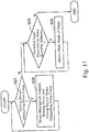
- Fig. 10 is a view showing one example of the control process flow.
- the first step is to determine whether an abnormal load is present by monitoring of the load using the state quantity detection portion 80 (step S11 in Fig. 10 ).
- Various methods may be used to evaluate whether the abnormal load is present.
- the controller 110 determines whether or not the load generated in the meshing portion falls within a predetermined permissible range from the result of detection by the load sensors 40 constituting the state quantity detection portions 80.
- the "permissible range" can be set as appropriate in accordance with a specific device configuration and can be individually set based on a state quantity that makes it possible to effectively avoid trouble such as a breakage of the driving devices 10 or the ring gear 107.
- the controller 110 When it is determined that the load generated in the meshing portion is within the predetermined permissible range and no abnormal load is present ("N" of S11), the controller 110 does not perform a load reduction process. In this case, the step S11 (see Fig. 10 ) is performed periodically to determine whether an abnormal load is present by monitoring of the load using the state quantity detection portion 80.
- the controller 110 performs a process of reducing the load (step S12 in Fig. 10 ).
- the load reduction process is performed under the control of the controller 110.
- the load reduction process is performed to reduce or totally remove the load generated in the meshing portion between the drive gear 24a of the driving device 10 and the ring gear 107. The load reduction process will be described in detail later with reference to Fig. 11 .
- a drive force output from the drive gear 24a of one of the driving devices 10 may cause an excessive load generated in the meshing portion between the drive gears 24a of other driving devices 10 and the ring gear 107. Accordingly, when an excessive load is generated in the meshing portion between the drive gear 24a of one of the driving devices 10 and the ring gear 107, it is preferable to perform the load reduction process similarly for other driving devices 10 that share the ring gear 107 with the one of the driving devices 10.
- the controller 110 performs, after the load reduction process, control for test operation of the driving device 10 to check whether there is abnormality in test operation (step S13 in Fig. 11 ).
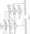
- the test operation process will be described in detail later with reference to Figs. 12 and 13 .
- the controller 110 when the state quantity detection portion 80 detects abnormality, the controller 110 first performs the process for reducing the load and then performs control for test operation of a plurality of driving devices 10 to check whether abnormality is present. That is, upon detection of abnormality, power generation of the wind turbine 101 is not immediately stopped, and instead, the load reduction process is performed to reduce the risk of breakage of the driving devices 10 and breakage of the ring gear 107 and the components therearound. The test operation of the driving devices 10 is then performed in the state where the load in the meshing portion is reduced, so as to determine whether the cause of the abnormal load is temporary. Accordingly, it is possible to effectively improve the capacity utilization of the wind turbine while effectively preventing the breakage of the meshing portion.
- the load reduction process is performed when the state quantity detection portion 80 detects an abnormal load in the meshing portion, and the load reduction process is performed to reduce or remove the load in the meshing portion.
- the first step is to determine whether a driving device 10 is outputting a drive force (step S21 in Fig. 11 ). In other words, it is determined whether the driving device 10 is operating. In the example shown, it may be determined whether a voltage is applied to the electric motor 23 of the driving device 10.
- the controller 110 controls the driving device 10 such that the driving device 10 stops outputting a drive force from the drive gear 24a of the driving device 10 to the ring gear 107 (step S22 in Fig. 11 ).
- the drive force may act as an external force on the meshing portion of one of the driving devices 10 and cause an excessive load in the meshing portion.
- the excessive load generated in the meshing portion between the drive gear 24a of one of the driving devices 10 and the ring gear 107 can be effectively reduced or removed by stopping the output of a drive force from the drive gear 24a of the driving device 10 to the ring gear 107.
- the controller 110 controls the motor brake unit (brake mechanism) 50 such that the motor brake unit (brake mechanism) 50 brakes rotation.
- the controller 110 controls the motor brake unit 50 such that the motor brake unit 50 outputs a braking force.
- the motor brake unit 50 outputs a braking force, it is possible to effectively stop the drive gear 24a of the driving device 10 from outputting a drive force.
- the load generated in the meshing portion between the drive gear 24a and the ring gear 107 can be effectively reduced or removed
- the wind power received by the blade 105 acts to rotate the nacelle 103.
- step S21 in Fig. 12 The operations of determining whether a driving device 10 is outputting a drive force (step S21 in Fig. 12 ), control for stopping the output of a drive force, and output of a braking force are performed sequentially or simultaneously on all of the plurality of driving devices 10 included in one movable section of the wind turbine 101.
- each state quantity detection portion 80 monitors whether an abnormal load outside the permissible range is present in the meshing portion between the drive gear 24a of the corresponding driving device 10 and the ring gear 107.
- the driving device 10 adjusts the pitch angle ⁇ p of the blade 105 (step S24 in Fig. 11 ).
- the wind power received by the blade 105 acts on the movable section of the nacelle 103 and the tower 102 such that the rotor 104 faces leeward and the rotation axis of the rotor 104 is oriented along the wind direction.
- the position of the nacelle 103 is set such that the rotor 104 faces windward and the rotation axis of the rotor 104 is oriented along the wind direction. That is, the wind turbine 101 operating for power generation receives from the wind power both an external force that rotates the rotor 104 and an external force that rotates the nacelle 103 by 180°.
- the blade 105 receives the wind power efficiently when the pitch angle ⁇ p is larger, the pitch angle ⁇ p being contained between the rotation axis of the rotor and the surface of the blade 105.
- the pitch angle ⁇ p is smaller, the wind power received by the blade 105 is reduced. Therefore, in the position of feathering in which the pitch angle ⁇ p is the smallest, the wind power received by the blade 105 is the smallest. Therefore, when the blade 105 is rotated with respect to the rotor 104 so as to reduce the pitch angle ⁇ p, the force acting to rotate the nacelle 103 with respect to the tower 102 is reduced, and the load generated in the meshing portion can be effectively reduced accordingly.
- step S23 it is determined again whether an abnormal load is present by monitoring of the load using the state quantity detection portion 80 (step S23 in Fig. 11 ).
- the load in the meshing portion is normally small enough and thus the abnormal load is eliminated ("N" in step S23). Since the abnormal load is eliminated, the load reduction process is ended
- the pitch angle ⁇ p is reduced by a predetermined amount in one adjustment and, when the abnormal load is not eliminated, the pitch angle ⁇ p is reduced again by the predetermined amount.
- the reduction of the pitch angle ⁇ p is favorable for reducing the load, but it causes reduction of the rotational force received by the blade 105 from the wind power. As a result, the reduction of the pitch angle ⁇ p leads to reduction of the power generation efficiency. If the control process described herein is performed while operating the wind turbine 101, reducing the pitch angle ⁇ p by a predetermined amount makes it possible to continue power generation without excessively reducing the load generated in the meshing portion,
- the pitch angle ⁇ p is adjusted after the driving device 10 stops outputting the drive force and the motor brake unit (brake mechanism) 50 outputs the braking force.
- the adjustment of the pitch angle ⁇ p which reduces the power generation efficiently is performed only when the load was not reduced enough by stopping the output of the drive force and outputting the braking force. In this respect, it is also possible to continue power generation without excessively reducing the load generated in the meshing portion.
- the load reduction process includes stopping of the output of the drive force from the driving device 10, outputting the braking force from the motor brake unit (brake mechanism) 50, and the adjustment of the pitch angle ⁇ p.
- the load reduction process may have one or more of these steps omitted or include other steps. Further, the order of these steps in the load reduction process may be rearranged as necessary.
- Figs. 12 and 13 show different test operations.
- the controller 110 sequentially operates the plurality of driving devices 10 included in one movable section for test operation to check whether abnormality is present.
- the controller 110 simultaneously operates the plurality of driving devices 10 included in one movable section for test operation to check whether abnormality is present.
- the test operation process shown in Fig. 12 includes the first step to check whether abnormality is present in the motor brake unit (brake mechanism) 50 (step S31 in Fig. 12 ).
- the detection result of the brake mechanism sensor 83 may be used to determine whether abnormality is present in the motor brake unit (brake mechanism) 50.
- the brake mechanism sensor 83 it is possible to detect an abnormal state in which a malfunction of the motor brake unit 50 that serves as the brake mechanism occurs due to fixing of the armature 57 or the like.
- the motor brake unit (brake mechanism) 50 continues outputting a braking force when the controller 110 performs control for stopping the output of the braking force.
- the rotation of the drive gear 24a of the driving device 10 is restrained As a result, the rotation of the nacelle 103 with respect to the tower 102 is also restricted by meshing between the ring gear 107 and the drive gear 24a.
- the drive force output from other driving devices 10 or a rush of wind acts as an external force to generate an excessive load in the meshing portion of the ring gear 107 and any one of the drive gears 24a.
- Such abnormality in the motor brake unit 50 may be caused by fixing of movable parts occurring due to a change of environmental conditions such as humidity and temperature and depending on use conditions. The fixing may be eliminated easily by repeatedly turning on and off the control signals for operating the motor brake unit 50.
- the controller 110 performs control for operating the motor brake unit 50 (step S32 in Fig. 12 ). More specifically, the controller 110 performs control for switching the motor brake unit 50 from the state where it outputs a braking force to the state where it stops output of the braking force, or the controller 110 performs control for switching the motor brake unit 50 from the state where it stops output of the braking force to the state where it outputs the braking force.
- An attempt to perform such a test operation may eliminate slight fixing and enable the motor brake unit 50 having abnormality to operate normally. Therefore, in the test operation process shown in Fig. 12 , the controller 110 performs control for operating the motor brake unit (brake mechanism) 50 and then checks again whether the abnormality is present in the motor brake unit (brake mechanism) 50.
- step S33 the controller 110 then checks whether the number of times it performed the control for operating the motor brake unit 50 exceeds a predetermined number (step S33 in Fig. 12 ).
- the controller 110 determines that there is abnormality that may cause an abnormal load and thus should be handled
- the controller 110 determines that a non-temporary abnormality is present and handles this abnormality in some way (step S14 in Fig. 10 ).
- a disconnection means such as a clutch may disconnect the drive shaft 48a from the drive gear 24a in each driving device 10.
- the controller 110 When it is determined that no abnormality is present in the motor brake unit (brake mechanism) ("N" of step S31), the controller 110 performs control for operating the driving device 10 (step S34 in Fig. 12 ). In other words, the controller 110 controls the driving device 10 for a test operation. More specifically, the controller 110 performs control for switching the driving device 10 from the state where it stops output of the drive force to the state where it outputs the drive force.
- the test operation of the driving device 10 may cause an excessive load in the meshing portion of the ring gear 107 and the drive gear 24a that leads to breakage of the driving device 10 or the ring gear 107.
- the controller 110 may control the driving device 10 so as to output a drive force from the drive gear 24a to the ring gear 107 at a lower torque than in normal operation.
- the controller 110 may control the driving device 10 so as to output a drive force from the drive gear 24a to the ring gear 107 at a lower number of rotations than in normal operation. Such control effectively protects the drive gear 24a and the ring gear 107 from being broken due to the test operation.
- the controller 110 After performing the control for operating the driving device 10, the controller 110 checks whether a malfunction is present in the driving device 10 (step S35 in Fig. 12 ). For example, the controller 110 checks whether the drive shaft 48a of the motor drive unit 48 and the drive gear 24a could operate (rotate) by a predetermined amount (step S35 in Fig. 12 ). When a malfunction of the driving device 10 is found, the controller 110 checks whether the number of times it performed the control for operating the driving device 10 exceeds a predetermined number (step S36 in Fig. 12 ). When the number of times the controller 110 performed the control for operating the driving device 10 does not exceed a predetermined number ("N" of step S36 in Fig. 12 ), the controller 110 performs again the control for operating the driving device 10.
- step S36 determines that there is abnormality that may cause an abnormal load and thus should be handled At this time, the controller 110 determines that a non-temporary abnormality is present and handles this abnormality in some way (step S14 in Fig. 10 ).
- a backlash (a clearance) is present between the teeth of the drive gears 24a and the teeth of the ring gear 107. Accordingly, in starting operation of a plurality of driving devices 10, the plurality of driving devices 10 may need to rotate respective drive gears 24a by different amounts until the teeth of the drive gears 24a contact with the teeth of the ring gear 107. Immediately after the plurality of driving devices 10 start operation, the teeth of the drive gear 24a of one driving device 10 first contact with the teeth of the ring gear 107, and power is transmitted from this driving device 10 to the ring gear 107.
- an excessive load may be generated
- the excessive load that may be generated in this manner is not a failure of the wind turbine 101 to be repaired but is caused by variation of operation between the drive gears 24a of the plurality of driving devices 10.
- the cause of the excessive load can be eliminated by sequentially rotating the plurality of driving devices 10 in the same direction by small amounts until the teeth of each drive gear 24a contact with the teeth of the ring gear 107. Therefore, the amount of operation (the amount of rotation) of the drive gear 24a in the test operation should be less than one pitch of the teeth of the drive gear 24a, or in particular, about the same as the amount of backlash between the drive gears 24a and the ring gear 107.
- the determination of whether abnormality is present in the brake mechanism (step S31 in Fig. 12 ) and the control for operating the brake mechanism for test operation (steps S32 and S33 in Fig. 12 ) may be either sequentially or simultaneously performed on the plurality of driving devices 10 included in one movable section.
- the control for operating the drive mechanism for test operation and the check on a malfunction in test operation (steps S34 to S36 in Fig. 12 ), which are affected by the test operation of other driving devices 10, are sequentially performed on each of the plurality of driving devices 10 included in one movable section.
- the controller 110 determines that there is abnormality that may cause an abnormal load and thus should be handled (step S14 in Fig. 10 ).
- no abnormality is found in the test operation of all of the driving devices 10 included in one movable section ("N" of step S35 in Fig.
- the controller 110 determines that no abnormality was found in the test operation process ("N" of step S13 in Fig. 10 ). In this case, the controller 110 determines that the cause of the detected abnormal load was temporary and has already been eliminated, and checks again whether an abnormal load is present by monitoring of the load using the state quantity detection portion 80 (step S11 in Fig. 10 ).
- the test operation process shown in Fig. 13 includes determination of whether abnormality is present in the brake mechanism (step S41 in Fig. 13 ) and the control for test operation of the brake mechanism (steps S42 and S43 in Fig. 13 ). These control processes may be the same as the determination of whether abnormality is present in the brake mechanism (step S31 in Fig. 12 ) and the control for test operation of the brake mechanism (steps S32 and S33 in Fig. 12 ), which were described above for the test operation process shown in Fig. 12 .
- the determination of whether abnormality is present in the brake mechanism (step S41 in Fig. 13 ) and the control for operating the brake mechanism for test operation (steps S42 and S43 in Fig. 13 ) may be either sequentially or simultaneously performed on the plurality of driving devices 10 included in one movable section of the wind turbine 101.
- the controller 110 determines that there is abnormality that may cause an abnormal load and thus should be handled (step S14 in Fig. 10 ).
- the controller 110 performs control for operating the driving devices 10.
- the controller 110 performs control for operating the driving devices 10 (step S44 in Fig. 13 ). More specifically, the controller 110 performs control for switching the plurality of driving devices 10 simultaneously from the state where they stop output of the drive force to the state where they output the drive force. In this test operation, the controller 110 may control the driving devices 10 so as to output a drive force from the drive gears 24a to the ring gear 107 at a lower torque or a lower number of rotations than in normal operation. Such control effectively protects the drive gear 24a and the ring gear 107 from being broken due to the test operation.
- the controller 110 After performing the control for simultaneously operating the plurality of driving devices 10 for test operation, the controller 110 checks whether abnormality is present in the rotation of the nacelle (step S45 in Fig. 13 ). For example, controller 110 checks whether the nacelle (one structure) 103 could operate by a predetermined amount with respect to the tower (the other structure) 102. When a malfunction of the nacelle 103 is found, the controller 110 checks whether the number of times it performed the control for operating the driving device 10 exceeds a predetermined number (step S46 in Fig. 13 ). When the number of times the controller 110 performed the control for operating the driving device 10 does not exceed a predetermined number ("N" of step S46 in Fig. 13 ), the controller 110 performs again the control for operating the driving device 10.
- the controller 110 determines that there is abnormality that may cause an abnormal load and thus should be handled At this time, the controller 110 determines that a non-temporary abnormality is present and handles this abnormality in some way (step S14 in Fig. 10 ).
- the test operation simultaneously performed by the plurality of driving devices 10 as shown in Fig. 3 also brings the teeth of the drive gears 24a of all the driving devices 10 into contact with the teeth of the ring gear 107. Accordingly, it is possible to eliminate through test operation the abnormal load caused by the variation of the operation between the drive gears 24a of the plurality of driving devices 10. Further, it is also possible to determine whether this non-temporary cause has been eliminated, by checking whether the nacelle (one structure) 103 could operate by a predetermined amount with respect to the tower (the other structure) 102.
- the amount of relative operation (the amount of relative rotation) of the tower 102 and the nacelle 103 may be less than one pitch of the teeth of the drive gear 24a, or in particular, about the same as the amount of backlash between the drive gears 24a and the ring gear 107.
- the controller 110 determines that there is abnormality that may cause an abnormal load and thus should be handled (step S14 in Fig. 10 ).
- the controller 110 determines that no abnormality was found in the test operation process ("N" of step S13 in Fig. 10 ). In this case, the controller 110 determines that the cause of the detected abnormal load was temporary and has already been eliminated, and checks again whether an abnormal load is present by monitoring of the load using the state quantity detection portion 80 (step S11 in Fig. 10 ).
- the wind turbine drive system 5 includes: a plurality of driving devices 10 installed in one structure 103 at a movable section of a wind turbine 101, each of the plurality of driving devices 10 including a drive gear 24a meshing with a ring gear 107 installed in another structure 102 at the movable section of the wind turbine 101; a state quantity detection unit (state quantity detection portion) 80 for monitoring, for each of the plurality of driving devices 10, a load generated between the drive gear 24a of each of the plurality of driving devices 10 and the ring gear 107; and a control unit (controller) 110 for performing control for reducing the load when the state quantity detection unit 80 detects an abnormal load
- the control unit 110 controls the wind turbine 101 so as to reduce a load in the meshing portion.
- the control unit 110 controls the plurality of driving devices 10 so as to stop the output from the drive gears 24a of all the driving devices 10 included in the plurality of driving devices 10 to the ring gear 107.
- an excessive load in the meshing portion in a driving device 10 is caused by a drive force output from the same driving device 10 or a drive force output from other driving devices 10.
- output of a drive force from another driving device 10 may cause an excessive load in the meshing portion of one of the driving devices. Accordingly, the load generated in the meshing portion can be quickly and effectively reduced by stopping, upon detection of the abnormal load, the output of a drive force from the drive gears 24a of all the driving devices 10 to the ring gear 107.
- the driving devices 10 each include the brake mechanism (motor brake unit) 50 for braking the rotation transmitted to the drive gear 24a or the rotation output from the drive gear 24a.
- the control unit 110 controls the brake mechanism 50 such that the brake mechanism 50 brakes the rotation.
- an excessive load in the meshing portion in a driving device 10 is caused by a drive force output from other driving devices 10 or a rush of wind Accordingly, when the brake mechanism 50 brakes the rotation transmitted to the drive gear 24a or the rotation output from the drive gear 24a, the load generated in the meshing portion can be reduced effectively.
- the control unit 110 adjusts the pitch angle ⁇ p of the blade 105 included in the wind turbine 101.
- an excessive load in the meshing portion in a driving device 10 is caused by a strong wind received by the wind turbine 101 through the blade 105.
- the force that the wind turbine 101 receives from the strong wind can be relieved by adjusting the pitch angle ⁇ p of the blade 105. Accordingly, the load generated in the meshing portion can be reduced effectively by adjusting the pitch angle ⁇ p of the blade 105.
- the control unit 110 when the state quantity detection unit detects an abnormal load, the control unit 110 first controls the plurality of driving devices 10 so as to stop the output from the drive gears 24a of all the driving devices 10 included in the plurality of driving devices 10 to the ring gear 107.
- the load generated in the meshing portion can be quickly and effectively reduced by stopping the output of a drive force from the drive gears 24a of the plurality of driving devices 10 to the ring gear 107.
- the load in the meshing portion may not be reduced enough only by stopping the output of the drive force from the driving devices 10.
- the control unit 110 when the abnormal load was not eliminated by stopping the output from the drive gears 24a to the ring gear 107, the control unit 110 then adjusts the pitch angle ⁇ p of the blade 105 included in the wind turbine 101 thereby to attempt to effectively reduce the load generated in the meshing portion. That is, in the embodiment, the load reduction process for reducing the load in the meshing portion includes first stopping the output of the drive force and then, when the load was not effectively reduced, adjusting the pitch angle ⁇ p that may affect the power generation efficiency. Therefore, it is possible to effectively prevent the breakage of the meshing portion due to the reduction of the load, while effectively raising the capacity utilization of the wind turbine 101.
- the control unit 110 when the state quantity detection unit 80 detects abnormality, the control unit 110 first performs the process for reducing the load and then controls either simultaneously or sequentially the plurality of driving devices 10 for the test operation.
- the load in the meshing portion upon detection of an abnormal load, the load in the meshing portion is reduced first.
- the test operation of the driving devices 10 is then performed in the state where the load in the meshing portion is reduced, so as to determine whether the cause of the abnormal load is temporary.
- the reduction of the load in the meshing portion makes it possible to continue the operation of the wind turbine 101 while effectively preventing the breakage of the driving devices 10 and the breakage of the ring gear 107 and the components therearound Accordingly, it is possible to effectively improve the capacity utilization of the wind turbine 101 while effectively preventing the breakage of the meshing portion.
- control unit 110 controls the plurality of driving devices 10 for the test operation so as to output a drive force at a lower torque than in normal operation. Since the driving devices 10 performs the test operation at a lower torque, it is possible to determine whether the cause of the abnormal load is temporary while effectively preventing a rapid increase of the load generated in the meshing portion. Accordingly, it is possible to effectively improve the capacity utilization of the wind turbine 101 while effectively preventing the breakage of the meshing portion.
- control unit 110 controls the plurality of driving devices 10 so as to perform the test operation simultaneously, thereby to check whether the one structure (the nacelle) 103 and the other structure (the tower) 102 could operate relative to each other.
- control unit 110 controls the driving devices 10 to operate at a lower torque and check whether the one structure 103 and the other structure 102 could operate relative to each other, thereby to determine whether the cause of the excessive load generated in the meshing portion was temporary. Accordingly, it is possible to effectively improve the capacity utilization of the wind turbine 101 while effectively preventing the breakage of the meshing portion.
- control unit 110 controls the plurality of driving devices 10 so as to perform the test operation sequentially, thereby to check whether the drive gears 24a of the driving devices 10 could operate by a predetermined amount that is less than one pitch of the teeth of the drive gears 24a.
- a backlash (a clearance) is present between the teeth of the drive gears 24a and the teeth of the ring gear 107. Accordingly, in starting operation of the plurality of driving devices 10, the plurality of driving devices 10 may rotate respective drive gears 24a by different amounts until the teeth of the drive gears 24a contact with the teeth of the ring gear 107.
- the teeth of the drive gear 24a of one driving device 10 first contact with the teeth of the ring gear 107, and power is transmitted from this driving device 10 to the ring gear 107.
- an excessive load may be generated Accordingly, handling of the temporary cause of the excessive load generated in the meshing portion is possible through the determination of whether the drive gears 24a of the driving devices 10 could operate at a lower torque or a lower rotation speed by a predetermined amount that is less than one pitch of the teeth of the drive gears 24a. Accordingly, it is possible to effectively improve the capacity utilization of the wind turbine 101 while effectively preventing the breakage of the meshing portion.
- the control unit 110 when the state quantity detection unit 80 detects abnormality, the control unit 110 first performs the process for reducing the load and then controls the brake mechanism 50 for the test operation. Unwanted fixing of moving parts of the brake mechanism 50 may occur due to a change of environmental conditions or depending on use conditions.
- a driving device 10 outputs a drive force in the state where the brake mechanism is unintentionally braking the rotation, the drive force may act as an external force on the meshing portion in any of the driving devices 10 to generate an excessive load.
- the fixing of the brake mechanism 50 may be eliminated by repeatedly turning on and off the control signals for operating the brake mechanism 50.
- the control unit 110 first performs the process for reducing the load and then controls the brake mechanism 50 for the test operation. Therefore, it is possible to eliminate a malfunction of the brake mechanism 50 that may have been the cause of the excessive load, while effectively preventing the excessive load from continuing to act on the meshing portion. Accordingly, it is possible to effectively improve the capacity utilization of the wind turbine 101 while effectively preventing the breakage of the meshing portion.
- control unit 110 controls the plurality of driving devices 10 for the test operation such that the brake mechanisms 50 operate first and then a drive force is output from the drive gears 24a to the ring gear 107.
- a temporary fault in the brake mechanisms 50 can be eliminated before the driving devices 10 output a drive force from the drive gears 24a.
- test operation process shown in Figs. 12 and 13 which includes both the control of the brake mechanisms for the test operation and the control of the driving devices for the test operation, may also be configured to additionally include another test operation that replaces one or more of the control of the brake mechanisms for the test operation and the control of the driving devices for the test operation.
- the brake mechanism is configured as the motor brake unit 50 that is built in the electric motor 23 and configured to brake the rotation of the drive shaft 48a of the motor drive unit 48.
- the brake mechanism may be configured to brake the rotation of one or more of the components included in the speed reducing unit 25, the output shaft 24, and the drive gear 24a.
Landscapes
- Engineering & Computer Science (AREA)
- General Engineering & Computer Science (AREA)
- Mechanical Engineering (AREA)
- Life Sciences & Earth Sciences (AREA)
- Sustainable Development (AREA)
- Sustainable Energy (AREA)
- Chemical & Material Sciences (AREA)
- Combustion & Propulsion (AREA)
- Wind Motors (AREA)
- Gear Transmission (AREA)
- Connection Of Motors, Electrical Generators, Mechanical Devices, And The Like (AREA)
- Structures Of Non-Positive Displacement Pumps (AREA)
Abstract
Description
- The present invention relates to a wind turbine drive system used for a movable section of a wind turbine, and the wind turbine.
- A wind turbine used as a wind power generator has been known as disclosed in, for example, Japanese Patent Application Publication
2015-140777 - For some reason, a large force may be generated at a meshing portion between a drive gear, which is an output portion of the driving device, and a ring gear meshing with the drive gear. For example, in starting operation of a plurality of driving devices, the plurality of driving devices may rotate respective drive gears by different amounts until the teeth of the drive gears contact with the teeth of the ring gear. Accordingly, in starting operation of a plurality of driving devices, an excessive load may be generated at a meshing portion of each driving device at which the amount of rotation of the drive gear until the teeth of the drive gear contact with the teeth of the ring gear is the smallest. When rotation of the drive gear of one driving device is restricted due to a failure or for some other reason, output of a drive force from another driving device may cause an excessive load in the meshing portion of one of the driving devices. Further, it is presumable that a rush of wind may impart an external force that causes an excessive load in the meshing portion of one of the driving devices.
- When the force generated in the meshing portion becomes large, the driving device or ring gear may be broken. If the driving device is broken, it is necessary to replace part or all of the driving device. If the ring gear or a structure around the ring gear is broken, a large-scale repair work will be required, and the operation of the wind turbine has to be stopped for a long period of time. To address such faults, it is effective, when a large load is generated in the meshing portion, to first stop power generation of the wind turbine and investigate the cause.
- The variation of the amounts of rotation of the drive gears required until the teeth of the drive gears contact with the teeth of the ring gear ceases when the movable section starts relative rotation. Unwanted fixing of a brake mechanism may occur due to a change of environmental conditions or depending on use conditions. The fixing may be eliminated by repeatedly turning on and off the control signals for operating the brake mechanism. That is, some of the causes of the excessive load generated in the meshing portion is temporary. Stopping the power generation of the wind turbine in such cases reduces the capacity utilization significantly.
- The present invention addresses the above drawbacks and one object thereof is to improve the control upon detecting an excessive load in the movable section of a wind turbine to raise the capacity utilization of the wind turbine. In particular, the present invention is aimed at appropriate handling of an abnormal load generated by temporary causes thereby to raise the capacity utilization of the wind turbine.
- A wind turbine drive system of the present invention includes: a plurality of driving devices installed in one structure at a movable section of a wind turbine, each of the plurality of driving devices including a drive gear meshing with a ring gear installed in another structure at the movable section of the wind turbine; a state quantity detection unit for monitoring, for each of the plurality of driving devices, a load generated between the drive gear of each of the plurality of driving devices and the ring gear; and a control unit for performing control for reducing the load when the state quantity detection unit detects an abnormal load
- The wind turbine drive system of the present invention may be configured such that when the state quantity detection unit detects an abnormal load, the control unit controls the plurality of driving devices so as to stop output from the drive gear of each of all the driving devices included in the plurality of driving devices to the ring gear.
- The wind turbine drive system of the present invention may be configured such that each of the plurality of driving devices includes a brake mechanism that brakes rotation transmitted to the drive gear or rotation output from the drive gear; and when the state quantity detection unit detects an abnormal load, the control unit controls the brake mechanism of each of the plurality of driving devices such that the brake mechanism brakes rotation.
- The wind turbine drive system of the present invention may be configured such that when the state quantity detection unit detects an abnormal load, the control unit adjusts a pitch angle of a blade included in the wind turbine.
- The wind turbine drive system of the present invention may be configured such that when the state quantity detection unit detects an abnormal load, the control unit controls the plurality of driving devices so as to stop output from the drive gear of each of all the driving devices included in the plurality of driving devices to the ring gear, and then, when the abnormal load is not eliminated, adjusts a pitch angle of a blade included in the wind turbine.
- The wind turbine drive system of the present invention may be configured such that when the state quantity detection unit detects an abnormal load, the control unit first performs a process for reducing the bad and then controls either simultaneously or sequentially the plurality of driving devices for test operation.
- The wind turbine drive system of the present invention may be configured such that the control unit controls the plurality of driving devices for the test operation so as to output a drive force from the drive gear of each of the plurality of driving devices to the ring gear at a lower torque than in normal operation.
- The wind turbine drive system of the present invention may be configured such that the control unit controls the plurality of driving devices so as to perform the test operation simultaneously and checks whether the one structure and the other structure operated relative to each other.
- The wind turbine drive system of the present invention may be configured such that the control unit controls the plurality of driving devices so as to perform the test operation sequentially and checks whether the drive gear of each of the plurality of driving devices operated by a predetermined amount that is less than one pitch of teeth of the drive gear.
- The wind turbine drive system of the present invention may be configured such that each of the plurality of driving devices includes a brake mechanism that brakes rotation transmitted to the drive gear or rotation output from the drive gear; and the control unit controls the plurality of driving devices such that the brake mechanism of each of the plurality of driving devices operates for test operation.
- The wind turbine drive system of the present invention may be configured such that the control unit controls the plurality of driving devices for the test operation such that the brake mechanism of each of the plurality of driving devices operates first and then the drive force is output from the drive gear of each of the plurality of driving devices to the ring gear.
- A wind turbine according to the present invention includes any one of the above wind turbine drive systems according to the present invention.
- The present invention improves the control upon detecting an excessive load in the movable section of a wind turbine, thereby to raise the capacity utilization of the wind turbine.
-
-
Fig. 1 is a perspective view of a wind turbine according to an embodiment of the invention. -
Fig. 2 is a side view of a part of the wind turbine ofFig. 1 for describing the operation of a blade of the wind turbine. -
Fig. 3 is a side view of a part of the wind turbine ofFig. 1 for describing the operation of a blade of the wind turbine. -
Fig. 4 is a sectional view of a part of a tower and a nacelle of the wind turbine ofFig. 1 . -
Fig. 5 is a plan view showing an arrangement of driving devices in a movable section shown inFig. 5 . -
Fig. 6 is a view of a driving device ofFig. 4 as seen from a lateral side, part of which is shown in longitudinal-section. -
Fig. 7 is a view of an installation portion of the driving device ofFig. 4 , part of which is shown in longitudinal-section. -
Fig. 8 schematically shows a brake mechanism of the driving device shown inFig. 4 . -
Fig. 9 is a block diagram for explaining a functional configuration of a controller. -
Fig. 10 is a view showing one example of a control process flow. -
Fig. 11 is a view showing one example of a load reduction process flow included in the control process flow ofFig. 10 . -
Fig. 12 is a view showing one example of a test operation process flow included in the control process fbw ofFig. 10 . -
Fig. 13 is a view showing another example of the test operation process flow. - An embodiment of the present invention will now be described with reference to the appended drawings. In the drawings, for ease of illustration and understanding, a scale size, a dimensional ratio, and so on are altered or exaggerated as appropriate from actual values.
-
Fig. 1 is a perspective view of awind turbine 101.Figs. 2 and 3 are side views of a part of the wind turbine.Fig. 4 is a sectional view showing part of atower 102 and anacelle 103. InFig. 4 ,driving devices 10 are shown with an outer appearance thereof instead of a cross-section thereof.Fig. 5 is a plan view showing an arrangement of thedriving devices 10 in a movable section shown inFig. 4 .Fig. 6 is a side view of one of thedriving devices 10, part of which is shown in longitudinal-section.Fig. 7 is a view showing an installation portion of thedriving device 10, part of which is shown in longitudinal-section.Fig. 8 is a view showing a brake mechanism of thedriving device 10 in longitudinal-section. - The
driving device 10 is capable of driving thenacelle 103 installed so as to be rotatable with respect to thetower 102 of thewind turbine 101 or driving ablade 105 installed so as to be swingable in a pitch direction with respect to arotor 104 mounted to thenacelle 103. That is, the drivingdevice 10 can be used as a yaw driving device for carrying out yaw driving so as to cause thenacelle 103 to rotate with respect to thetower 102 and also as a pitch driving device for carrying out pitch driving so as to cause a shaft portion of theblade 105 to rotate with respect to therotor 104. While the following describes an example in which thedriving device 10 is used as a yaw driving device, the present invention is applicable also to a case where the drivingdevice 10 is used as a pitch driving device. - As shown in
Fig. 1 , thewind turbine 101 includes thetower 102, thenacelle 103, therotor 104, theblade 105, and so on. Thetower 102 extends upward in a vertical direction from the ground Thenacelle 103 is installed on a top portion of thetower 102 so as to be rotatable relative thereto. Rotation of thenacelle 103 with respect to thetower 102 is yaw rotation about a longitudinal direction of thetower 102 as a rotation center. In the example shown, thenacelle 103 is driven by a plurality of drivingdevices 10 to rotate with respect to thetower 102. Thenacelle 103 contains devices installed therein for wind power generation, such as a power transmission shaft, an electric power generator connected to the power transmission shaft. Therotor 104 is connected to the power transmission shaft and is rotatable with respect to thenacelle 103. A plurality of blades 105 (threeblades 105 in the example shown inFig. 1 ) extend from therotor 104 in radial directions about a rotation axis of therotor 104 that rotates with respect to thenacelle 103. The plurality ofblades 105 are arranged at equal angular intervals. - As shown in
Figs. 2 and 3 , theblades 105 are each rotatable in the pitch direction. More specifically, theblades 105 are each rotatable about a longitudinal direction thereof with respect to therotor 104. A connection point between theblades 105 and therotor 104 is configured as a movable section so that theblades 105 and therotor 104 are rotatable relative to each other. Theblades 105 are driven to rotate by a driving device provided as a pitch driving device. The driving device as the pitch driving device may be configured similarly to an after-mentioneddriving device 10 as a yaw driving device. - In operation of the
wind turbine 101 ofFig. 1 for power generation, the pitch angle θp of theblade 105 is adjusted in accordance with the wind velocity. When the wind is relatively soft, the pitch angle θp is set to a large value, as shown inFig. 2 , such that theblade 105 receives the wind power positively. When the wind becomes stronger, the pitch angle θp is set to a small value, as shown inFig. 3 , to prevent therotor 104 from rotating at an excessively high speed. When strong wind blows at a velocity higher than a predetermined value, the orientation of theblade 105 is set to a position of feathering with the pitch angle θp of approximately 0°. In the examples shown inFigs. 2 and 3 , the pitch angle θp is defined as an angle contained between the rotation axis of the rotor and the surface of theblade 105. As the pitch angle θp is larger, theblade 105 receives the wind power more efficiently. On the other hand, when the pitch angle θp is smaller, the wind power received by theblade 105 is reduced Therefore, the wind power received by theblade 105 in the position of feathering is the smallest. - In operation of the
wind turbine 101, the position of thenacelle 103 is set such that therotor 104 faces the wind straight. More specifically, in operation of thewind turbine 101, the position of thenacelle 103 is set such that therotor 104 faces windward and the rotation axis of therotor 104 is oriented along the wind direction. In operation of thewind turbine 101, the wind power received by theblade 105 acts as an external force to turn thenacelle 103 by 180°. More specifically, the wind power acts on the movable section of thenacelle 103 and thetower 102 such that therotor 104 faces leeward and the rotation axis of therotor 104 is oriented along the wind direction. Accordingly, the force acting on the movable section can be reduced as the pitch angle θp of theblade 105 is smaller. - As shown in
Fig. 4 , thenacelle 103 is installed on the top of thetower 102 so as to be rotatable relative thereto via abearing 106 interposed between abottom portion 103a of thenacelle 103 and thetower 102. Aring gear 107 having internal teeth formed on an inner periphery thereof is fixed to the top portion of thetower 102. Thering gear 107 may have external teeth provided on an outer periphery thereof, instead of the internal teeth provided on the inner periphery thereof. In the drawings, the teeth of thering gear 107 are not shown. - As shown in
Fig. 4 andFig. 5 , the plurality of drivingdevices 10 are provided in the nacelle 103 (a first structure), not in the tower 102 (a second structure), both configured to rotate relative to each other. Each of the drivingdevices 10 includes adrive gear 24a meshing with the teeth of thering gear 10 provided in thetower 102. As shown inFig. 6 , each of the drivingdevices 10 is provided with anelectric motor 23 and aspeed reducing unit 25. Theelectric motor 23 includes a motor drive unit and a motor brake unit (described later), and thespeed reducing unit 25 receives power transmitted from the electric motor 23 (particularly, the motor drive unit). The motor drive unit outputs a drive force (rotational power), and the motor brake unit brakes the motor drive unit to reduce the drive force (rotational power) outputted from the motor drive unit. The term "braking" used herein is to be broadly construed, and a definition thereof embraces retaining a stopped state of an object that has been stopped and stopping a moving object. - By driving of the driving
devices 10 thus configured, it is possible to cause the nacelle 103 (the first structure) as one side of a movable section of thewind turbine 101 to rotate with respect to the tower 102 (the second structure) as the other side of the movable section of thewind turbine 101. Particularly, the plurality of drivingdevices 10 included in the wind turbine are operated in a synchronized manner and thus provide drive power of a magnitude sufficient to cause thenacelle 103, which is a heavy object, to properly swivel with respect to thetower 102. The drivingdevices 10 operate based on a control signal sent from a controller 110 (a control unit, seeFig. 9 ) (described later) to the electric motor 23 (the motor drive unit and the motor brake unit). The plurality of drivingdevices 10 collectively constitute a driving device unit. Further, the driving device unit, thecontroller 110, and a state quantity detecting portion 80 (described later) constitute the windturbine drive system 5. - As shown in
Fig. 5 , thering gear 107 is formed in a circumferential shape and has a center axis Cm. Thenacelle 103 rotates about the center axis Cm of thering gear 107. In an example shown, the center axis Cm of thering gear 107 corresponds to the longitudinal direction of thetower 102. In the following description, a direction parallel to the center axis Cm of thering gear 107 is simply referred to also as an "axial direction dl" - In the
wind turbine 101 shown, as shown inFig. 5 , there are provided a pair of driving device groups arranged in rotational symmetry about the center axis Cm of thering gear 107. Each driving device group includes threedriving devices 10. In the illustrated example, sixdriving devices 10 included in the pair of driving device groups constitute the driving device unit 9,Bodies 20 of the driving devices are arranged along a circumference cl1 (seeFig. 5 ) about the center axis Cm of thering gear 107. The threedriving devices 10 included in each driving device group are arranged at given intervals along the circumference cl1. - Each of the driving
devices 10 has adriving device body 20 fixed to thenacelle 103. As shown inFig. 7 , each of the drivingdevices 10 is fixed to the nacelle 103 (the first structure) via afastener 30 disposed so as to extend through a throughhole 22a formed through aflange 22 of thedriving device body 20. Moreover, each of the drivingdevices 10 includes a load sensor 40 (seeFig. 7 ) for finding any abnormality in thedriving device body 20. As will be described later, theload sensor 40 can indirectly detect a load (stress) between thedrive gear 24a of each of the drivingdevices 10 and thering gear 107. Preferably, theload sensor 40 is mounted to a location on which no other disturbance than a load between thedrive gear 24a and thering gear 107 acts or is likely to act. In the example shown, theload sensor 40 serves as a sensor that measures a change in the state of thefastener 30. Thefastener 30 changes its state in conjunction with a load (stress) produced between thedrive gear 24a of each of the drivingdevices 10 and thering gear 107. Theload sensor 40 shown is disposed to contact with thefastener 30, and it is also possible that theload sensor 40 is disposed on the case to monitor a change in the state of the case. - As shown in
Fig. 6 , the drivingdevice body 20 is provided with anoutput shaft 24 having thedrive gear 24a that meshes with thering gear 107, thecase 21 rotatably retaining theoutput shaft 24, and theelectric motor 23 fixed to thecase 21. Furthermore, the drivingdevice body 20 is provided further with thespeed reducing unit 25 housed in thecase 21 and connecting theelectric motor 23 to theoutput shaft 24. Thespeed reducing unit 25 decelerates an input (rotational power) from theelectric motor 23 while increasing a torque thereof and transmits the input to theoutput shaft 24. While there is no particular limitation on a specific configuration of thespeed reducing unit 25 thus described, thespeed reducing unit 25 can typically adopt an eccentric oscillating gear-type speed reducing mechanism, a planetary gear-type speed reducing mechanism, or a speed reducing mechanism combining the eccentric oscillating gear-type and the planetary gear-type. - An end portion of the
output shaft 24 distal from thespeed reducing unit 25 extends out from thecase 21, and thedrive gear 24a is formed at this extending-out portion of theoutput shaft 24. As shown inFig. 4 andFig. 7 , theoutput shaft 24 penetrates through a throughhole 103b formed through thebottom portion 103a of thenacelle 103 and meshes with thering gear 107. Thedrive gear 24a has a shape adapted to thering gear 107. As one example, thedrive gear 24a can be formed as a pinion gear having external teeth configured to mesh with the internal teeth of thering gear 107. Each of the drivingdevices 10 has a longitudinal axis corresponding to a rotation axis Cr of theoutput shaft 24. In a state where each of the drivingdevices 10 is fixed to thenacelle 103, the rotation axis Cr of theoutput shaft 24 is parallel to an axial direction dl of thewind turbine 101. - The
case 21 is formed in a cylindrical shape as shown inFig. 6 and is disposed so that a longitudinal axis thereof is positioned in the rotation axis Cr as shown inFig. 7 . Thecase 21 is open at both ends thereof along the rotation axis Cr. Thedrive gear 24a of theoutput shaft 24 is exposed from an opening of thecase 21 near thetower 102. Theelectric motor 23 is mounted to an opening of thecase 21 on an opposite side to thetower 102. Furthermore, thecase 21 includes theflange 22. As shown inFig. 5 , theflange 22 of this example is formed in an annular shape and extends along a circumference cl3 about the rotation axis Cr of theoutput shaft 24. As shown inFig. 6 andFig. 7 , the throughhole 22a is formed through theflange 22 so as to extend in the axial direction dl. A multitude of throughholes 22a are formed on a circumference cl3 about the rotation axis Cr of theoutput shaft 24. In an example shown, twelve throughholes 22a are formed - The
fasteners 30 penetrate through theflange 20 by extending through the throughholes 22a formed through theflange 22 of thedriving device body 20. In the example shown inFig. 7 , each of thefasteners 30 includes abolt 30a and anut 30b. Thebolt 30a penetrates through theflange 22 of thedriving device body 20 and thebottom portion 103a of thenacelle 103. Thenut 30b is screwed with thebolt 30a in a direction from thetower 102. Thefastener 30 formed of a combination of thebolt 30a and thenut 30b is provided for each of the throughholes 22a of thedriving device body 20. In the example shown, the drivingdevice bodies 20 are mounted to thenacelle 103 at twelve locations with twelvefasteners 30. - The
fastener 30 is not limited to the illustrated example. Thefastener 30 may be configured such that, instead of using thenut 30b, a female screw with which a male screw of thebolt 30a can be screwed is formed along a through hole of thenacelle 103. In this case, thefastener 30 is formed of thebolt 30a, and the male screw of thebolt 30a meshes with the female screw in the through hole of thenacelle 103, thus making it possible to fix thedriving device body 20 to thenacelle 103. - The
load sensor 40 measures a change in state of thefastener 30 and thus can directly or indirectly measure an amount of a force acting on thefastener 30. Specifically, theload sensor 40 may be formed of a known sensor for measuring one or more of a load applied to thefastener 30, a displacement of thefastener 30 with respect to thenacelle 103, and a relative position of thefastener 30 to thenacelle 103. In the example shown, an axial force sensor is used as thesensor 40, and thus it is possible to measure a load (an axial force) toward a particular direction applied to thefastener 30. As another example, a magnetic sensor or a photoelectric sensor may be used as thesensor 40 to measure a position and a displacement of thefastener 30 in a non-contact manner. - The
fastener 30 changes its state in conjunction with a load (stress) produced between thedrive gear 24a of each of the drivingdevices 10 and thering gear 107. Therefore, by monitoring a change in the state offastener 30 with theload sensor 40, it is possible to evaluate the magnitude of the load (stress) produced in the meshing portion between thedrive gear 24a and thering gear 107. - As shown in
Fig. 7 , theload sensor 40 is fixedly retained with a jig 49 to thenacelle 103, which is one side of the movable section. The axial force sensor constituting theload sensor 40 contacts with a head portion of thebolt 30a as a component of thefastener 30. There is, however, no limitation to this example, As shown by a chain double-dashed line inFig. 7 , theload sensor 40 may contact with a distal end portion of thebolt 30a on an opposite side to the head portion or may contact with thenut 30b. Furthermore, theload sensor 40 may detect a load applied to a fastening bolt fastening thenacelle 103 to thecase 21. - The
load sensor 40 is electrically connected to the controller 110 (seeFig. 9 ) (described later), and an electric signal related to a result of measurement outputted from theload sensor 40 is transmitted to thecontroller 110. Thecontroller 110 monitors the electric signal outputted from thesensor 40, and thus it is possible to grasp a change in load applied to thefastener 30 and a displacement of thefastener 30. Based on a result of measurement by theload sensor 40, thecontroller 110 can control the various types of constituent elements of thewind turbine 101, such as the drivingdevices 10. - Next, the
electric motor 23 will now be described In the example shown, theelectric motor 23 includes amotor drive unit 48 and amotor brake unit 50.Fig. 8 is a view schematically showing a partial longitudinal section of theelectric motor 23. Themotor brake unit 50 is a brake mechanism that brakes a rotational motion conveyed to thedrive gear 24a. However, as will be described later, instead of or in addition to themotor brake unit 50, the drivingdevice body 20 may include various forms of brake mechanism that brakes the rotational motion conveyed to thedrive gear 24a or the rotational motion output from thedrive gear 24a. - The
electric motor 23 provided with amotor drive unit 48 and amotor brake unit 50 is provided in each of the drivingdevices 10, and onemotor brake unit 50 is mounted to eachmotor drive unit 48. Themotor drive unit 48 can be formed of any device capable of controlling the number of rotations of adrive shaft 48a based on a command from the controller 110 (seeFig. 9 ). Themotor brake unit 50 shown includes a mechanism as an electromagnetic brake for braking rotation of thedrive shaft 48a of themotor drive unit 48 or releasing thedrive shaft 48a from being braked, based on a command from the controller 110 (seeFig. 9 ). In a state where rotation of thedrive shaft 48a is braked, the number of rotations of thedrive shaft 48a is reduced, and thus eventually, thedrive shaft 48a can be completely stopped from rotating. On the other hand, in a state where thedrive shaft 48a is released from being braked, thedrive shaft 48a can rotate, without being braked by themotor braking portion 50, basically at a proper number of rotations corresponding to electric power supplied to themotor drive unit 48. The drive force (rotational power) from thedrive shaft 48a of themotor drive unit 48 is transmitted to theoutput shaft 24 via thespeed reducing unit 25. - The
motor brake unit 50 of this example is mounted to an end portion of acover 72 of themotor drive unit 48 on an opposite side to thespeed reducing unit 25 and includes ahousing 51, afriction plate 56, anarmature 57, anelastic member 55, anelectromagnet 53, a first frictionplate connecting portion 77, and so on. Thehousing 51 is a structure that houses thefriction plate 56, thearmature 57, theelastic member 55, theelectromagnet 53, the first frictionplate connecting portion 77, and so on and is fixed to thecover 72 of themotor drive unit 48. Thefriction plate 56 is connected to thedrive shaft 48a of themotor drive unit 48 via the first frictionplate connecting portion 77. Thefriction plate 56 has a through hole that is penetrated by one end portion of thedrive shaft 48a. - The first friction
plate connecting portion 77 of this example includes aspline shaft 77a and aslide shaft 77b. Thespline shaft 77a is fixed to an outer periphery of the one end portion of thedrive shaft 48a through key coupling via a key member (not shown) and engagement with astopper ring 77c. Theslide shaft 77b is mounted to thespline shaft 77a so as to be slidable in an axial direction. Furthermore, the first frictionplate connecting portion 77 is provided with a spring mechanism (not shown) for situating theslide shaft 77b at a predetermined position in the axial direction with respect to thespline shaft 77a. An inner periphery of thefriction plate 56 is fixed to an edge portion of an outer periphery of a flange-shaped portion of theslide shaft 77b, so that thefriction plate 56 is coupled integrally with theslide shaft 77b. - The
motor brake unit 50 described above is configured such that, when thedrive shaft 48a rotates, thespline shaft 77a, theslide shaft 77b, and thefriction plate 56 also rotate together with thedrive shaft 48a. In a state where the after-mentionedelectromagnet 53 is excited, theslide shaft 77b and thefriction plate 56 that are retained so as to be slidable in the axial direction with respect to thedrive shaft 48a and thespline shaft 77a are situated at a predetermined position in the axial direction of thespline shaft 77a by the spring mechanism. When disposed at this predetermined position, thefriction plate 56 is separated from thearmature 57 and afriction plate 58, which will be described later. - The
armature 57 is contactable with thefriction plate 56 and generates a braking force for braking rotation of thedrive shaft 48a when contacting with thefriction plate 56. Furthermore, in this example, thefriction plate 58 is provided at a location on one end portion of thecover 72 of themotor drive unit 48, where thefriction plate 58 is opposed to thefriction plate 56. Thefriction plate 58 is installed at such a position as to be contactable with thefriction plate 56. - The
elastic member 55 is retained in anelectromagnetic body 53a of theelectromagnet 53, which will be described later, and biases thearmature 57 in a direction from theelectromagnet 53 toward thefriction plate 56. Particularly in this example, theelastic member 55 in theelectromagnetic body 53a includes two arrays ofelastic members 55 arranged on the inner peripheral side and the outer peripheral side in the circumferential direction so as to be concentric about thedrive shaft 48a. The above-mentioned form of arranging theelastic members 55 is merely an example, and theelastic members 55 may be arranged in any other form. - The
electromagnet 53 includes theelectromagnetic body 53a and acoil portion 53b and attracts thearmature 57 by a magnetic force so as to separate thearmature 57 from thefriction plate 56. Theelectromagnetic body 53a is fixed to thehousing 51, and in particular, fixed thereto at an end portion of theelectromagnetic body 53a on an opposite side to where theelectromagnetic body 53a is opposed to thearmature 57. Theelectromagnetic body 53a has a plurality of elasticmember retaining holes 53c open toward thearmature 57, and theelastic members 55 are disposed in the elasticmember retaining holes 53c, respectively. Thecoil portion 53b is installed inside theelectromagnetic body 53a and disposed along the circumferential direction of theelectromagnetic body 53a. Supplying and shutting off of an electric current to thecoil portion 53b is performed based on a command of thecontroller 110. - For example, when the
motor brake unit 50 releases thedrive shaft 48a from being braked, an electric current is supplied to thecoil portion 53b to energize theelectromagnet 53, based on a command of thecontroller 110. When theelectromagnet 53 is energized and thus is brought into an exited state, thearmature 57 is attracted to thecoil portion 53b by a magnetic force generated at theelectromagnet 53. At this time, thearmature 57 is attracted to theelectromagnet 53 against an elastic force (a spring force) of the plurality ofelastic members 55. With this configuration, thearmature 57 is separated from thefriction plate 56, and thus thedrive shaft 48a is released from being braked Accordingly, in a state where theelectromagnet 53 is excited and thus thedrive shaft 48a is released from being braked, thearmature 57 is brought into contact with theelectromagnetic body 53a. - On the other hand, when the
motor brake unit 50 brakes thedrive shaft 48a, a supply of an electric current to thecoil portion 53b is shut off to demagnetize theelectromagnet 53, based on a command of thecontroller 110. When theelectromagnet 53 is brought into a demagnetized state, thearmature 57 is biased toward thefriction plate 56 by an elastic force of the plurality ofelastic members 55, and thus thearmature 57 contacts with thefriction plate 56. With this configuration, a friction force is generated between thearmature 57 and thefriction plate 56, and thus rotation of thedrive shaft 48a is brakedFig. 8 shows a state where theelectromagnet 53 is demagnetized, in which rotation of thedrive shaft 48a is braked - Furthermore, in a state where the
electromagnet 53 is demagnetized and thus thedrive shaft 48a is braked, thefriction plate 56 is in contact also with thefriction plate 58 under a biasing force acting from thearmature 57. Accordingly, when theelectromagnet 53 is demagnetized, thefriction plate 56 is sandwiched between thearmature 57 and thefriction plate 58 under a biasing force from the plurality ofelastic members 55. With this configuration, rotation of thedrive shaft 48a is braked by a friction force generated between thearmature 57 and thefriction plate 56 and a friction force generated between thefriction plate 56 and thefriction plate 58. - Further, in the example shown, a brake mechanism sensor 83 is provided to monitor the operation of the brake mechanism. In the example shown in
Fig. 8 , the brake mechanism sensor 83 monitors the position of thearmature 57 along the axial direction dl. With the brake mechanism sensor 83 monitoring the position of thearmature 57 along the axial direction dl, it can be determined whether themotor brake unit 50 is operating in accordance with the control of thecontroller 110. - The brake mechanism sensor 83 shown in
Fig. 8 includes adetection target portion 83b attached to thearmature 57, and a detection unit 83a that detects the position and displacement of thedetection target portion 83b in a direction parallel to the axial direction dl. Thedetection target portion 83b in this example is permanent magnet fixed to thearmature 57 and may be attached to a part of the outer peripheral portion of thearmature 57 close to theelectromagnet 53. The detection unit 83a is provided as a sensor capable of detecting the position and displacement of thedetection target portion 83b that moves together with thearmature 57. That is, the detection unit 83a detects the position and displacement of thedetection target portion 83b in the direction parallel to the rotation axis Cr of thedrive shaft 48a, to detect the position and displacement of thearmature 57 in the direction parallel to the rotation axis Cr of thedrive shaft 48a. The detection unit 83a illustrated is provided as a sensor that measures an intensity and a direction of a magnetic field generated by the detection target portion 83 which is permanent magnet, and the detection unit 83a is fixed to an inner wall of thehousing 51. The detection unit 83a detects the position and displacement of thedetection target portion 83b by measuring the intensity and direction of the magnetic field generated by thedetection target portion 83b. Thus, the detection unit 83a is preferably fixed to thehousing 51 at a position corresponding to thedetection target portion 83b in the direction parallel to the rotation axis Cr of thedrive shaft 48a. - In the
wind turbine 101 as described above, a large force may be generated for some reason at a meshing portion between thedrive gear 24a of thedriving device body 20 and thering gear 107. For example, when rotation of the drive gear of one driving device is restricted due to a failure or for some other reason and a drive force is output from another driving device, the drive force may act as an external force on the meshing portion of one of the drivingdevices 10 and cause an excessive load in the meshing portion. When thewind turbine 101 is subjected to a rush of wind or receives a strong wind in starting the operation of the drivingdevices 10, an excessive load may be generated in the meshing portion of one of the drivingdevices 10. The excessive load generated in the meshing portion causes breakage of thedrive gear 24a and thespeed reducing unit 25, which requires repair or replacement of thedriving device body 20. The excessive load on the meshing portion also causes breakage of thering gear 107 or components around thering gear 107. If thering gear 107 or components around the ring gear is broken, a large-scale repair work will be required, and the operation of the wind turbine has to be stopped for a long period of time. To address such faults, it is effective, when a large load is generated in the meshing portion, to stop power generation of the wind turbine and conduct investigation of the cause and repair. - However, some of the causes of the excessive load in the meshing portion is temporary. For example, when the excessive load is generated only by a rush of wind, the excessive load will be removed as the elapse of time. In such a case, it is preferable to reduce the load generated in the meshing portion, but there is no need of stopping the operation of the
wind turbine 101 to conduct investigation and repair. If the operation of thewind turbine 101 is stopped when the excessive load is generated due to a temporary cause, the capacity utilization of thewind turbine 101 is reduced significantly. Therefore, in the windturbine drive system 5 described herein, the components of thewind turbine 101 are controlled in a more sophisticated manner when an excessive load is detected in the movable section of the wind turbine, making it possible to effectively raise the capacity utilization of thewind turbine 101 while effectively preventing the breakage of thedriving device body 20 and thering gear 107. - A description will be hereinafter given of a control method for effectively raising the capacity utilization of the
wind turbine 101 while effectively preventing the breakage of thedriving device body 20 and thering gear 107. -
Fig. 9 is a block diagram for explaining a functional configuration of thecontroller 110. In this example, the above-mentionedload sensor 40 is used as a state quantity detection portion (a state quantity detection unit) 80. Thecontroller 110 receives a result of detection from each of theload sensors 40 provided in the plurality of driving devices 10 (in this example, six driving devices 10), and outputs a control signal for controlling themotor drive unit 48 and the motor brake unit (brake mechanism) 50 provided in each of the drivingdevices 10. There is no particular limitation on an installation position of thecontroller 110. Thecontroller 110 may be provided integrally with any of the elements constituting the wind turbine 101 (for example, thetower 102, thenacelle 103, therotor 104, or the blade 105) or provided independently of these elements. - The state
quantity detection portion 80 is provided in each of the drivingdevices 10 and configured to directly or indirectly detect a load between thedrive gear 24a of a corresponding one of the drivingdevices 10 and thering gear 107. The statequantity detection portion 80 can be formed of any sensor. In this example, the above-mentionedload sensor 40 functions as the statequantity detection portion 80. That is, an amount of a force acting on thefastener 30 is measured by the load sensor 40 (the state quantity detection portion 80) so as to detect "a load generated between thedrive gear 24a and thering gear 107," and a result of the detection is sent from each of theload sensors 40 to thecontroller 110. - The state
quantity detection portion 80 is not limited to theload sensor 40 for detecting a state quantity of thefastener 30 and can be formed of any type of sensor capable of detecting any state quantity varying depending on a magnitude of "a load between thedrive gear 24a and thering gear 107." For example, a sensor capable of measuring an amount of a force acting on the speed reducing unit 25 (for example, a sensor for detecting a distortion generated in the speed reducing unit 25) can be installed in thespeed reducing unit 25 of each of the drivingdevices 10 and used as the statequantity detection portion 80 to detect "a load between the meshingportion 24a and thering gear 107." Further, it is also possible that the statequantity detection portion 80 includes a sensor that monitors control currents of theelectric motor 23. - The
controller 110 performs control for adjusting the orientation of thenacelle 103 and the pitch angle θp of theblade 105. Thecontroller 110 is capable of controlling the operation of themotor drive unit 48 and themotor brake unit 50 by any method, thereby to control the orientation of thenacelle 103, for example. Further, when thedrive shaft 48a of themotor drive unit 48 of each drivingdevice 10 is rotating, thecontroller 110 may adjust the number of rotations and the torque output from eachmotor drive unit 48. For example, the number of rotations and the torque of themotor drive unit 48 can be directly adjusted by changing, by use of an inverter, a frequency or a voltage of electricity supplied to themotor drive unit 48. - Next, a description is given of an example of a control process flow using the
controller 110. - First, with reference to
Fig. 10 , the control process flow is outlined for the case where an excessive load is generated in the meshing portion between thedrive gear 24a and thering gear 107. -
Fig. 10 is a view showing one example of the control process flow. In this example, the first step is to determine whether an abnormal load is present by monitoring of the load using the state quantity detection portion 80 (step S11 inFig. 10 ). Various methods may be used to evaluate whether the abnormal load is present. In the example shown, thecontroller 110 determines whether or not the load generated in the meshing portion falls within a predetermined permissible range from the result of detection by theload sensors 40 constituting the statequantity detection portions 80. The "permissible range" can be set as appropriate in accordance with a specific device configuration and can be individually set based on a state quantity that makes it possible to effectively avoid trouble such as a breakage of the drivingdevices 10 or thering gear 107. - When it is determined that the load generated in the meshing portion is within the predetermined permissible range and no abnormal load is present ("N" of S11), the
controller 110 does not perform a load reduction process. In this case, the step S11 (seeFig. 10 ) is performed periodically to determine whether an abnormal load is present by monitoring of the load using the statequantity detection portion 80. - On the other hand, when it is determined that the load generated in the meshing portion is outside the predetermined permissible range and an abnormal load is present ("Y" of S11), the
controller 110 performs a process of reducing the load (step S12 inFig. 10 ). In the presence of the abnormal load, there is a risk of breakage of the drive gears 24a of the drivingdevices 10 and breakage of thering gear 107 and the components therearound To avoid breakage of the drivingdevices 10 and thering gear 107, the load reduction process is performed under the control of thecontroller 110. The load reduction process is performed to reduce or totally remove the load generated in the meshing portion between thedrive gear 24a of the drivingdevice 10 and thering gear 107. The load reduction process will be described in detail later with reference toFig. 11 . - As described above, a drive force output from the
drive gear 24a of one of the drivingdevices 10 may cause an excessive load generated in the meshing portion between the drive gears 24a ofother driving devices 10 and thering gear 107. Accordingly, when an excessive load is generated in the meshing portion between thedrive gear 24a of one of the drivingdevices 10 and thering gear 107, it is preferable to perform the load reduction process similarly forother driving devices 10 that share thering gear 107 with the one of the drivingdevices 10. - When the load reduction process is performed to reduce the load in the meshing portion, it is possible to reduce the risk of breakage of the drive gears 24a of the driving
devices 10 and breakage of thering gear 107 and the components therearound. As shown inFig. 11 , thecontroller 110 performs, after the load reduction process, control for test operation of the drivingdevice 10 to check whether there is abnormality in test operation (step S13 inFig. 11 ). The test operation process will be described in detail later with reference toFigs. 12 and13 . - When abnormality is found in the test operation ("Y" of S13), there is possibility that a fault not temporary is present. In such a case, power generation of the
wind turbine 101 may be stopped, for example, to conduct trouble shooting. When no abnormality is found in the test operation ("N" of S13), there is possibility that the cause of the excessive load was temporary. Therefore, it is determined again whether an abnormal load is present by monitoring of the load using the state quantity detection portion 80 (step S11 inFig. 10 ). - In the control process flow described above, when the state
quantity detection portion 80 detects abnormality, thecontroller 110 first performs the process for reducing the load and then performs control for test operation of a plurality of drivingdevices 10 to check whether abnormality is present. That is, upon detection of abnormality, power generation of thewind turbine 101 is not immediately stopped, and instead, the load reduction process is performed to reduce the risk of breakage of the drivingdevices 10 and breakage of thering gear 107 and the components therearound. The test operation of the drivingdevices 10 is then performed in the state where the load in the meshing portion is reduced, so as to determine whether the cause of the abnormal load is temporary. Accordingly, it is possible to effectively improve the capacity utilization of the wind turbine while effectively preventing the breakage of the meshing portion. - Next, with reference to
Fig. 11 , a description is given of the load reduction process performed by thecontroller 110. The load reduction process is performed when the statequantity detection portion 80 detects an abnormal load in the meshing portion, and the load reduction process is performed to reduce or remove the load in the meshing portion. - In the example shown in
Fig. 11 , the first step is to determine whether a drivingdevice 10 is outputting a drive force (step S21 inFig. 11 ). In other words, it is determined whether the drivingdevice 10 is operating. In the example shown, it may be determined whether a voltage is applied to theelectric motor 23 of the drivingdevice 10. - When the driving
device 10 is outputting a drive force ("Y" of step S21 inFig. 11 ), thecontroller 110 controls the drivingdevice 10 such that the drivingdevice 10 stops outputting a drive force from thedrive gear 24a of the drivingdevice 10 to the ring gear 107 (step S22 inFig. 11 ). For example, when rotation of thedrive gear 24a of onedriving device 10 is restricted due to a failure or for some other reason and a drive force is output from another driving device, the drive force may act as an external force on the meshing portion of one of the drivingdevices 10 and cause an excessive load in the meshing portion. Accordingly, the excessive load generated in the meshing portion between thedrive gear 24a of one of the drivingdevices 10 and thering gear 107 can be effectively reduced or removed by stopping the output of a drive force from thedrive gear 24a of the drivingdevice 10 to thering gear 107. - In the example shown, when the driving
device 10 is outputting a drive force ("Y" of step S21 inFig. 11 ), thecontroller 110 controls the motor brake unit (brake mechanism) 50 such that the motor brake unit (brake mechanism) 50 brakes rotation. In other words, thecontroller 110 controls themotor brake unit 50 such that themotor brake unit 50 outputs a braking force. When themotor brake unit 50 outputs a braking force, it is possible to effectively stop thedrive gear 24a of the drivingdevice 10 from outputting a drive force. Thus, the load generated in the meshing portion between thedrive gear 24a and thering gear 107 can be effectively reduced or removed The wind power received by theblade 105 acts to rotate thenacelle 103. When a rush of wind acts as an external force to rotate thenacelle 103, a load is generated in the meshing portion between thering gear 107 and thedrive gear 24a. When the motor brake unit (brake mechanism) 50 outputs a braking force to stop thenacelle 103 from rotating with respect to thetower 102, the load generated in the meshing portion can be reduced effectively. - The operations of determining whether a driving
device 10 is outputting a drive force (step S21 inFig. 12 ), control for stopping the output of a drive force, and output of a braking force are performed sequentially or simultaneously on all of the plurality of drivingdevices 10 included in one movable section of thewind turbine 101. - When the driving
device 10 is stopped from outputting a drive force ("N" of step S21 inFig. 11 ), it is determined whether an abnormal load is present by monitoring of the load using the state quantity detection portion 80 (step S23 inFig. 11 ). This step is performed in the same manner as the step S11 inFig. 10 described above. In the example shown, each statequantity detection portion 80 monitors whether an abnormal load outside the permissible range is present in the meshing portion between thedrive gear 24a of thecorresponding driving device 10 and thering gear 107. - When the
controller 110 determines that an abnormal load is present from the detection result of the state quantity detection portion 80 ("Y" of step S23), the drivingdevice 10 adjusts the pitch angle θp of the blade 105 (step S24 inFig. 11 ). - As described above, the wind power received by the
blade 105 acts on the movable section of thenacelle 103 and thetower 102 such that therotor 104 faces leeward and the rotation axis of therotor 104 is oriented along the wind direction. In operation of thewind turbine 101, the position of thenacelle 103 is set such that therotor 104 faces windward and the rotation axis of therotor 104 is oriented along the wind direction. That is, thewind turbine 101 operating for power generation receives from the wind power both an external force that rotates therotor 104 and an external force that rotates thenacelle 103 by 180°. - As shown in
Figs. 2 and 3 , theblade 105 receives the wind power efficiently when the pitch angle θp is larger, the pitch angle θp being contained between the rotation axis of the rotor and the surface of theblade 105. On the other hand, when the pitch angle θp is smaller, the wind power received by theblade 105 is reduced. Therefore, in the position of feathering in which the pitch angle θp is the smallest, the wind power received by theblade 105 is the smallest. Therefore, when theblade 105 is rotated with respect to therotor 104 so as to reduce the pitch angle θp, the force acting to rotate thenacelle 103 with respect to thetower 102 is reduced, and the load generated in the meshing portion can be effectively reduced accordingly. - In this example shown in
Fig. 11 , after adjustment of the pitch angle, it is determined again whether an abnormal load is present by monitoring of the load using the state quantity detection portion 80 (step S23 inFig. 11 ). When output of the drive force from the drivingdevice 10 is stopped and the pitch angle θp is adjusted to the feathering state where the pitch angle θp is the smallest, the load in the meshing portion is normally small enough and thus the abnormal load is eliminated ("N" in step S23). Since the abnormal load is eliminated, the load reduction process is ended - It is also possible that the pitch angle θp is reduced by a predetermined amount in one adjustment and, when the abnormal load is not eliminated, the pitch angle θp is reduced again by the predetermined amount. The reduction of the pitch angle θp is favorable for reducing the load, but it causes reduction of the rotational force received by the
blade 105 from the wind power. As a result, the reduction of the pitch angle θp leads to reduction of the power generation efficiency. If the control process described herein is performed while operating thewind turbine 101, reducing the pitch angle θp by a predetermined amount makes it possible to continue power generation without excessively reducing the load generated in the meshing portion, - In the load reduction process described above, the pitch angle θp is adjusted after the driving
device 10 stops outputting the drive force and the motor brake unit (brake mechanism) 50 outputs the braking force. The adjustment of the pitch angle θp which reduces the power generation efficiently is performed only when the load was not reduced enough by stopping the output of the drive force and outputting the braking force. In this respect, it is also possible to continue power generation without excessively reducing the load generated in the meshing portion. - In the example shown in
Fig. 11 , the load reduction process includes stopping of the output of the drive force from the drivingdevice 10, outputting the braking force from the motor brake unit (brake mechanism) 50, and the adjustment of the pitch angle θp. However, this example is not limitative. The load reduction process may have one or more of these steps omitted or include other steps. Further, the order of these steps in the load reduction process may be rearranged as necessary. - Next, with reference to
Figs. 12 and13 , a description is given of a specific example of a control process flow for performing a test operation to determine whether abnormality is present (step S13 inFig. 10 ).Figs. 12 and13 show different test operations. In the example of the test operation shown inFig. 12 , thecontroller 110 sequentially operates the plurality of drivingdevices 10 included in one movable section for test operation to check whether abnormality is present. By contrast, in the example of the test operation shown inFig. 13 , thecontroller 110 simultaneously operates the plurality of drivingdevices 10 included in one movable section for test operation to check whether abnormality is present. - First, the example of the test operation shown in
Fig. 12 is described The test operation process shown inFig. 12 , following the load reduction process (step S12 inFig. 10 ), includes the first step to check whether abnormality is present in the motor brake unit (brake mechanism) 50 (step S31 inFig. 12 ). In thewind turbine 101 shown, the detection result of the brake mechanism sensor 83 may be used to determine whether abnormality is present in the motor brake unit (brake mechanism) 50. By using the brake mechanism sensor 83, it is possible to detect an abnormal state in which a malfunction of themotor brake unit 50 that serves as the brake mechanism occurs due to fixing of thearmature 57 or the like. - One example of the malfunction is that the motor brake unit (brake mechanism) 50 continues outputting a braking force when the
controller 110 performs control for stopping the output of the braking force. In case of such a malfunction of themotor brake unit 50, the rotation of thedrive gear 24a of the drivingdevice 10 is restrained As a result, the rotation of thenacelle 103 with respect to thetower 102 is also restricted by meshing between thering gear 107 and thedrive gear 24a. At this time, the drive force output fromother driving devices 10 or a rush of wind acts as an external force to generate an excessive load in the meshing portion of thering gear 107 and any one of the drive gears 24a. Such abnormality in themotor brake unit 50 may be caused by fixing of movable parts occurring due to a change of environmental conditions such as humidity and temperature and depending on use conditions. The fixing may be eliminated easily by repeatedly turning on and off the control signals for operating themotor brake unit 50. - Therefore, when a malfunction of the motor brake unit (brake mechanism) 50 is found ("Y" of step S31), the
controller 110 performs control for operating the motor brake unit 50 (step S32 inFig. 12 ). More specifically, thecontroller 110 performs control for switching themotor brake unit 50 from the state where it outputs a braking force to the state where it stops output of the braking force, or thecontroller 110 performs control for switching themotor brake unit 50 from the state where it stops output of the braking force to the state where it outputs the braking force. An attempt to perform such a test operation may eliminate slight fixing and enable themotor brake unit 50 having abnormality to operate normally. Therefore, in the test operation process shown inFig. 12 , thecontroller 110 performs control for operating the motor brake unit (brake mechanism) 50 and then checks again whether the abnormality is present in the motor brake unit (brake mechanism) 50. - Each time the
controller 110 performs the control for operating the motor brake unit, thecontroller 110 then checks whether the number of times it performed the control for operating themotor brake unit 50 exceeds a predetermined number (step S33 inFig. 12 ). When the number of times the controller performed the control for operating themotor brake unit 50 exceeds the predetermined number ("Y" of step S33), thecontroller 110 determines that there is abnormality that may cause an abnormal load and thus should be handled At this time, thecontroller 110 determines that a non-temporary abnormality is present and handles this abnormality in some way (step S14 inFig. 10 ). For example, a disconnection means such as a clutch may disconnect thedrive shaft 48a from thedrive gear 24a in each drivingdevice 10. - When it is determined that no abnormality is present in the motor brake unit (brake mechanism) ("N" of step S31), the
controller 110 performs control for operating the driving device 10 (step S34 inFig. 12 ). In other words, thecontroller 110 controls the drivingdevice 10 for a test operation. More specifically, thecontroller 110 performs control for switching the drivingdevice 10 from the state where it stops output of the drive force to the state where it outputs the drive force. - There is possibility that the cause of the abnormal load still remains when the test operation of the driving
device 10 is performed Accordingly, the test operation of the drivingdevice 10 may cause an excessive load in the meshing portion of thering gear 107 and thedrive gear 24a that leads to breakage of the drivingdevice 10 or thering gear 107. To address such a fault, thecontroller 110 may control the drivingdevice 10 so as to output a drive force from thedrive gear 24a to thering gear 107 at a lower torque than in normal operation. Alternatively, thecontroller 110 may control the drivingdevice 10 so as to output a drive force from thedrive gear 24a to thering gear 107 at a lower number of rotations than in normal operation. Such control effectively protects thedrive gear 24a and thering gear 107 from being broken due to the test operation. - After performing the control for operating the driving
device 10, thecontroller 110 checks whether a malfunction is present in the driving device 10 (step S35 inFig. 12 ). For example, thecontroller 110 checks whether thedrive shaft 48a of themotor drive unit 48 and thedrive gear 24a could operate (rotate) by a predetermined amount (step S35 inFig. 12 ). When a malfunction of the drivingdevice 10 is found, thecontroller 110 checks whether the number of times it performed the control for operating the drivingdevice 10 exceeds a predetermined number (step S36 inFig. 12 ). When the number of times thecontroller 110 performed the control for operating the drivingdevice 10 does not exceed a predetermined number ("N" of step S36 inFig. 12 ), thecontroller 110 performs again the control for operating the drivingdevice 10. When the number of times the controller performed the control for operating the drivingdevice 10 exceeds the predetermined number ("Y" of step S36), thecontroller 110 determines that there is abnormality that may cause an abnormal load and thus should be handled At this time, thecontroller 110 determines that a non-temporary abnormality is present and handles this abnormality in some way (step S14 inFig. 10 ). - A backlash (a clearance) is present between the teeth of the drive gears 24a and the teeth of the
ring gear 107. Accordingly, in starting operation of a plurality of drivingdevices 10, the plurality of drivingdevices 10 may need to rotate respective drive gears 24a by different amounts until the teeth of the drive gears 24a contact with the teeth of thering gear 107. Immediately after the plurality of drivingdevices 10 start operation, the teeth of thedrive gear 24a of onedriving device 10 first contact with the teeth of thering gear 107, and power is transmitted from this drivingdevice 10 to thering gear 107. In the meshing portion of them, an excessive load may be generated The excessive load that may be generated in this manner is not a failure of thewind turbine 101 to be repaired but is caused by variation of operation between the drive gears 24a of the plurality of drivingdevices 10. The cause of the excessive load can be eliminated by sequentially rotating the plurality of drivingdevices 10 in the same direction by small amounts until the teeth of eachdrive gear 24a contact with the teeth of thering gear 107. Therefore, the amount of operation (the amount of rotation) of thedrive gear 24a in the test operation should be less than one pitch of the teeth of thedrive gear 24a, or in particular, about the same as the amount of backlash between the drive gears 24a and thering gear 107. - In the above example of the test operation process shown in
Fig. 12 , the determination of whether abnormality is present in the brake mechanism (step S31 inFig. 12 ) and the control for operating the brake mechanism for test operation (steps S32 and S33 inFig. 12 ) may be either sequentially or simultaneously performed on the plurality of drivingdevices 10 included in one movable section. The control for operating the drive mechanism for test operation and the check on a malfunction in test operation (steps S34 to S36 inFig. 12 ), which are affected by the test operation ofother driving devices 10, are sequentially performed on each of the plurality of drivingdevices 10 included in one movable section. - When the abnormality of the motor brake unit (brake mechanism) 50 in one or
more driving devices 10 is not eliminated by performing the control for the test operation of the motor brake unit (brake mechanism) 50 for more than the predetermined number of times ("Y" of S33 inFig. 12 ), or when the abnormality of the one ormore driving devices 10 is not eliminated by performing the control for the test operation of the drivingdevices 10 for more than the predetermined number of times ("Y" of S36 inFig. 12 ), thecontroller 110 determines that there is abnormality that may cause an abnormal load and thus should be handled (step S14 inFig. 10 ). When no abnormality is found in the test operation of all of the drivingdevices 10 included in one movable section ("N" of step S35 inFig. 12 ), thecontroller 110 determines that no abnormality was found in the test operation process ("N" of step S13 inFig. 10 ). In this case, thecontroller 110 determines that the cause of the detected abnormal load was temporary and has already been eliminated, and checks again whether an abnormal load is present by monitoring of the load using the state quantity detection portion 80 (step S11 inFig. 10 ). - Next, with reference to
Fig. 13 , a description is given of another example of the control process flow for performing a test operation to determine whether abnormality is present (step S13 inFig. 10 ). As with the test operation process shown inFig. 12 described above, the test operation process shown inFig. 13 includes determination of whether abnormality is present in the brake mechanism (step S41 inFig. 13 ) and the control for test operation of the brake mechanism (steps S42 and S43 inFig. 13 ). These control processes may be the same as the determination of whether abnormality is present in the brake mechanism (step S31 inFig. 12 ) and the control for test operation of the brake mechanism (steps S32 and S33 inFig. 12 ), which were described above for the test operation process shown inFig. 12 . - In the example shown in
Fig. 13 , the determination of whether abnormality is present in the brake mechanism (step S41 inFig. 13 ) and the control for operating the brake mechanism for test operation (steps S42 and S43 inFig. 13 ) may be either sequentially or simultaneously performed on the plurality of drivingdevices 10 included in one movable section of thewind turbine 101. When the abnormality of the motor brake unit (brake mechanism) 50 in one ormore driving devices 10 is not eliminated by performing the control for the test operation of the motor brake unit (brake mechanism) 50 for more than the predetermined number of times ("Y" of S43 inFig. 13 ), thecontroller 110 determines that there is abnormality that may cause an abnormal load and thus should be handled (step S14 inFig. 10 ). When it is determined that no abnormality is present in the motor brake units (brake mechanisms) of all of the driving devices 10 ("N" of step S41 inFig. 13 ), thecontroller 110 performs control for operating the drivingdevices 10. - At this time, the
controller 110 performs control for operating the driving devices 10 (step S44 inFig. 13 ). More specifically, thecontroller 110 performs control for switching the plurality of drivingdevices 10 simultaneously from the state where they stop output of the drive force to the state where they output the drive force. In this test operation, thecontroller 110 may control the drivingdevices 10 so as to output a drive force from the drive gears 24a to thering gear 107 at a lower torque or a lower number of rotations than in normal operation. Such control effectively protects thedrive gear 24a and thering gear 107 from being broken due to the test operation. - After performing the control for simultaneously operating the plurality of driving
devices 10 for test operation, thecontroller 110 checks whether abnormality is present in the rotation of the nacelle (step S45 inFig. 13 ). For example,controller 110 checks whether the nacelle (one structure) 103 could operate by a predetermined amount with respect to the tower (the other structure) 102. When a malfunction of thenacelle 103 is found, thecontroller 110 checks whether the number of times it performed the control for operating the drivingdevice 10 exceeds a predetermined number (step S46 inFig. 13 ). When the number of times thecontroller 110 performed the control for operating the drivingdevice 10 does not exceed a predetermined number ("N" of step S46 inFig. 13 ), thecontroller 110 performs again the control for operating the drivingdevice 10. When the number of times the controller performed the control for operating the drivingdevice 10 exceeds the predetermined number ("Y" of step S46), thecontroller 110 determines that there is abnormality that may cause an abnormal load and thus should be handled At this time, thecontroller 110 determines that a non-temporary abnormality is present and handles this abnormality in some way (step S14 inFig. 10 ). - The test operation simultaneously performed by the plurality of driving
devices 10 as shown inFig. 3 also brings the teeth of the drive gears 24a of all thedriving devices 10 into contact with the teeth of thering gear 107. Accordingly, it is possible to eliminate through test operation the abnormal load caused by the variation of the operation between the drive gears 24a of the plurality of drivingdevices 10. Further, it is also possible to determine whether this non-temporary cause has been eliminated, by checking whether the nacelle (one structure) 103 could operate by a predetermined amount with respect to the tower (the other structure) 102. At this time, the amount of relative operation (the amount of relative rotation) of thetower 102 and thenacelle 103 may be less than one pitch of the teeth of thedrive gear 24a, or in particular, about the same as the amount of backlash between the drive gears 24a and thering gear 107. - In the example shown in
Fig. 13 , when the abnormality in thedriving devices 10 is not eliminated by performing the control for the test operation of the plurality of drivingdevices 10 for more than the predetermined number of times ("Y" of S46 inFig. 13 ), thecontroller 110 determines that there is abnormality that may cause an abnormal load and thus should be handled (step S14 inFig. 10 ). When no abnormality is found in the operation of thenacelle 103 using the plurality of driving devices 10 ("N" of step S45 inFig. 13 ), thecontroller 110 determines that no abnormality was found in the test operation process ("N" of step S13 inFig. 10 ). In this case, thecontroller 110 determines that the cause of the detected abnormal load was temporary and has already been eliminated, and checks again whether an abnormal load is present by monitoring of the load using the state quantity detection portion 80 (step S11 inFig. 10 ). - As described above, in the embodiment, the wind
turbine drive system 5 includes: a plurality of drivingdevices 10 installed in onestructure 103 at a movable section of awind turbine 101, each of the plurality of drivingdevices 10 including adrive gear 24a meshing with aring gear 107 installed in anotherstructure 102 at the movable section of thewind turbine 101; a state quantity detection unit (state quantity detection portion) 80 for monitoring, for each of the plurality of drivingdevices 10, a load generated between thedrive gear 24a of each of the plurality of drivingdevices 10 and thering gear 107; and a control unit (controller) 110 for performing control for reducing the load when the statequantity detection unit 80 detects an abnormal load In the embodiment as described above, upon detection of an abnormal load, thecontrol unit 110 controls thewind turbine 101 so as to reduce a load in the meshing portion. Accordingly, upon detection of abnormality, power generation of thewind turbine 101 is not immediately stopped, and it is possible to effectively prevent the breakage of the drivingdevices 10 and the breakage of thering gear 107 and the components therearound Thus, the capacity utilization of thewind turbine 101 can be raised - In the embodiment, when the state quantity detection unit detects an abnormal load, the
control unit 110 controls the plurality of drivingdevices 10 so as to stop the output from the drive gears 24a of all thedriving devices 10 included in the plurality of drivingdevices 10 to thering gear 107. In many cases, an excessive load in the meshing portion in adriving device 10 is caused by a drive force output from thesame driving device 10 or a drive force output fromother driving devices 10. For example, when rotation of thedrive gear 24a of onedriving device 10 is restricted due to a failure or for some other reason, output of a drive force from another drivingdevice 10 may cause an excessive load in the meshing portion of one of the driving devices. Accordingly, the load generated in the meshing portion can be quickly and effectively reduced by stopping, upon detection of the abnormal load, the output of a drive force from the drive gears 24a of all thedriving devices 10 to thering gear 107. - Further, in the embodiment, the driving
devices 10 each include the brake mechanism (motor brake unit) 50 for braking the rotation transmitted to thedrive gear 24a or the rotation output from thedrive gear 24a. When the state quantity detection unit detects an abnormal load, thecontrol unit 110 controls thebrake mechanism 50 such that thebrake mechanism 50 brakes the rotation. In many cases, an excessive load in the meshing portion in adriving device 10 is caused by a drive force output fromother driving devices 10 or a rush of wind Accordingly, when thebrake mechanism 50 brakes the rotation transmitted to thedrive gear 24a or the rotation output from thedrive gear 24a, the load generated in the meshing portion can be reduced effectively. - Further, in the embodiment, when the state quantity detection unit detects an abnormal load, the
control unit 110 adjusts the pitch angle θp of theblade 105 included in thewind turbine 101. In many cases, an excessive load in the meshing portion in adriving device 10 is caused by a strong wind received by thewind turbine 101 through theblade 105. The force that thewind turbine 101 receives from the strong wind can be relieved by adjusting the pitch angle θp of theblade 105. Accordingly, the load generated in the meshing portion can be reduced effectively by adjusting the pitch angle θp of theblade 105. - Further, in the embodiment, when the state quantity detection unit detects an abnormal load, the
control unit 110 first controls the plurality of drivingdevices 10 so as to stop the output from the drive gears 24a of all thedriving devices 10 included in the plurality of drivingdevices 10 to thering gear 107. In many cases, the load generated in the meshing portion can be quickly and effectively reduced by stopping the output of a drive force from the drive gears 24a of the plurality of drivingdevices 10 to thering gear 107. When an excessive load is generated in the meshing portion primarily due to strong wind, the load in the meshing portion may not be reduced enough only by stopping the output of the drive force from the drivingdevices 10. In the embodiment, when the abnormal load was not eliminated by stopping the output from the drive gears 24a to thering gear 107, thecontrol unit 110 then adjusts the pitch angle θp of theblade 105 included in thewind turbine 101 thereby to attempt to effectively reduce the load generated in the meshing portion. That is, in the embodiment, the load reduction process for reducing the load in the meshing portion includes first stopping the output of the drive force and then, when the load was not effectively reduced, adjusting the pitch angle θp that may affect the power generation efficiency. Therefore, it is possible to effectively prevent the breakage of the meshing portion due to the reduction of the load, while effectively raising the capacity utilization of thewind turbine 101. - Further, in the embodiment, when the state
quantity detection unit 80 detects abnormality, thecontrol unit 110 first performs the process for reducing the load and then controls either simultaneously or sequentially the plurality of drivingdevices 10 for the test operation. In the embodiment as described above, upon detection of an abnormal load, the load in the meshing portion is reduced first. The test operation of the drivingdevices 10 is then performed in the state where the load in the meshing portion is reduced, so as to determine whether the cause of the abnormal load is temporary. During this operation, the reduction of the load in the meshing portion makes it possible to continue the operation of thewind turbine 101 while effectively preventing the breakage of the drivingdevices 10 and the breakage of thering gear 107 and the components therearound Accordingly, it is possible to effectively improve the capacity utilization of thewind turbine 101 while effectively preventing the breakage of the meshing portion. - Further, in the embodiment, the
control unit 110 controls the plurality of drivingdevices 10 for the test operation so as to output a drive force at a lower torque than in normal operation. Since the drivingdevices 10 performs the test operation at a lower torque, it is possible to determine whether the cause of the abnormal load is temporary while effectively preventing a rapid increase of the load generated in the meshing portion. Accordingly, it is possible to effectively improve the capacity utilization of thewind turbine 101 while effectively preventing the breakage of the meshing portion. - Further, in the embodiment, the
control unit 110 controls the plurality of drivingdevices 10 so as to perform the test operation simultaneously, thereby to check whether the one structure (the nacelle) 103 and the other structure (the tower) 102 could operate relative to each other. For example, thecontrol unit 110 controls the drivingdevices 10 to operate at a lower torque and check whether the onestructure 103 and theother structure 102 could operate relative to each other, thereby to determine whether the cause of the excessive load generated in the meshing portion was temporary. Accordingly, it is possible to effectively improve the capacity utilization of thewind turbine 101 while effectively preventing the breakage of the meshing portion. - Further, in the embodiment, the
control unit 110 controls the plurality of drivingdevices 10 so as to perform the test operation sequentially, thereby to check whether the drive gears 24a of the drivingdevices 10 could operate by a predetermined amount that is less than one pitch of the teeth of the drive gears 24a. A backlash (a clearance) is present between the teeth of the drive gears 24a and the teeth of thering gear 107. Accordingly, in starting operation of the plurality of drivingdevices 10, the plurality of drivingdevices 10 may rotate respective drive gears 24a by different amounts until the teeth of the drive gears 24a contact with the teeth of thering gear 107. In addition, immediately after the plurality of drivingdevices 10 start operation, the teeth of thedrive gear 24a of onedriving device 10 first contact with the teeth of thering gear 107, and power is transmitted from this drivingdevice 10 to thering gear 107. In the meshing portion of them, an excessive load may be generated Accordingly, handling of the temporary cause of the excessive load generated in the meshing portion is possible through the determination of whether the drive gears 24a of the drivingdevices 10 could operate at a lower torque or a lower rotation speed by a predetermined amount that is less than one pitch of the teeth of the drive gears 24a. Accordingly, it is possible to effectively improve the capacity utilization of thewind turbine 101 while effectively preventing the breakage of the meshing portion. - Further, in the embodiment, when the state
quantity detection unit 80 detects abnormality, thecontrol unit 110 first performs the process for reducing the load and then controls thebrake mechanism 50 for the test operation. Unwanted fixing of moving parts of thebrake mechanism 50 may occur due to a change of environmental conditions or depending on use conditions. When a drivingdevice 10 outputs a drive force in the state where the brake mechanism is unintentionally braking the rotation, the drive force may act as an external force on the meshing portion in any of the drivingdevices 10 to generate an excessive load. The fixing of thebrake mechanism 50 may be eliminated by repeatedly turning on and off the control signals for operating thebrake mechanism 50. More specifically, when the statequantity detection unit 80 detects abnormality, thecontrol unit 110 first performs the process for reducing the load and then controls thebrake mechanism 50 for the test operation. Therefore, it is possible to eliminate a malfunction of thebrake mechanism 50 that may have been the cause of the excessive load, while effectively preventing the excessive load from continuing to act on the meshing portion. Accordingly, it is possible to effectively improve the capacity utilization of thewind turbine 101 while effectively preventing the breakage of the meshing portion. - Further, in the embodiment, the
control unit 110 controls the plurality of drivingdevices 10 for the test operation such that thebrake mechanisms 50 operate first and then a drive force is output from the drive gears 24a to thering gear 107. In the embodiment, a temporary fault in thebrake mechanisms 50 can be eliminated before the drivingdevices 10 output a drive force from the drive gears 24a. Thus, it is possible to effectively prevent a rapid increase of the load generated in the meshing portion as the drivingdevices 10 output the drive force. - Various modifications can be made to the foregoing embodiment. The following describes one modification example. In the following description, parts that can be configured similarly to those in the foregoing embodiment are denoted by the same reference characters as those used for corresponding parts in the foregoing embodiment, and duplicate descriptions thereof are omitted
- For example, in the embodiment described above, the test operation process shown in
Figs. 12 and13 , which includes both the control of the brake mechanisms for the test operation and the control of the driving devices for the test operation, may also be configured to additionally include another test operation that replaces one or more of the control of the brake mechanisms for the test operation and the control of the driving devices for the test operation. - In the above embodiment, the brake mechanism is configured as the
motor brake unit 50 that is built in theelectric motor 23 and configured to brake the rotation of thedrive shaft 48a of themotor drive unit 48. However, this example is not limitative, and the brake mechanism may be configured to brake the rotation of one or more of the components included in thespeed reducing unit 25, theoutput shaft 24, and thedrive gear 24a.
Claims (12)
- A wind turbine drive system, comprising:a plurality of driving devices installed in one structure at a movable section of a wind turbine, each of the plurality of driving devices including a drive gear meshing with a ring gear installed in another structure at the movable section of the wind turbine;a state quantity detection unit for monitoring, for each of the plurality of driving devices, a load generated between the drive gear of each of the plurality of driving devices and the ring gear; anda control unit for performing control for reducing the load when the state quantity detection unit detects an abnormal load.
- The wind turbine drive system of claim 1, wherein when the state quantity detection unit detects an abnormal load, the control unit controls the plurality of driving devices so as to stop output from the drive gear of each of all the driving devices included in the plurality of driving devices to the ring gear.
- The wind turbine drive system of claim 1 or 2, wherein
each of the plurality of driving devices includes a brake mechanism that brakes rotation transmitted to the drive gear or rotation output from the drive gear; and
when the state quantity detection unit detects an abnormal load, the control unit controls the brake mechanism of each of the plurality of driving devices such that the brake mechanism brakes rotation. - The wind turbine drive system of any one of claims 1 to 3, wherein when the state quantity detection unit detects an abnormal load, the control unit adjusts a pitch angle of a blade included in the wind turbine.
- The wind turbine drive system of claim 1 or 3, wherein when the state quantity detection unit detects an abnormal load, the control unit controls the plurality of driving devices so as to stop output from the drive gear of each of all the driving devices included in the plurality of driving devices to the ring gear, and then, when the abnormal load is not eliminated, adjusts a pitch angle of a blade included in the wind turbine.
- The wind turbine drive system of any one of claims 1 to 5, wherein when the state quantity detection unit detects an abnormal load, the control unit first performs a process for reducing the load and then controls either simultaneously or sequentially the plurality of driving devices for test operation.
- The wind turbine drive system of claim 6, wherein the control unit controls the plurality of driving devices for the test operation so as to output a drive force from the drive gear of each of the plurality of driving devices to the ring gear at a lower torque than in normal operation.
- The wind turbine drive system of claim 6 or 7, wherein the control unit controls the plurality of driving devices so as to perform the test operation simultaneously and checks whether the one structure and the other structure operated relative to each other.
- The wind turbine drive system of claim 6 or 7, wherein the control unit controls the plurality of driving devices so as to perform the test operation sequentially and checks whether the drive gear of each of the plurality of driving devices operated by a predetermined amount that is less than one pitch of teeth of the drive gear.
- The wind turbine drive system of any one of claims 6 to 9, wherein
each of the plurality of driving devices includes a brake mechanism that brakes rotation transmitted to the drive gear or rotation output from the drive gear; and
the control unit controls the plurality of driving devices such that the brake mechanism of each of the plurality of driving devices operates for test operation. - The wind turbine drive system of any one of claims 6 to 9, wherein the control unit controls the plurality of driving devices for the test operation such that the brake mechanism of each of the plurality of driving devices operates first and then the drive force is output from the drive gear of each of the plurality of driving devices to the ring gear.
- A wind turbine comprising the wind turbine drive system of any one of claims 1 to 11.
Applications Claiming Priority (2)
| Application Number | Priority Date | Filing Date | Title |
|---|---|---|---|
| JP2016237726A JP6921514B2 (en) | 2016-12-07 | 2016-12-07 | Windmill drive system and windmill |
| PCT/JP2017/043064 WO2018105488A1 (en) | 2016-12-07 | 2017-11-30 | Windmill drive system and windmill |
Publications (3)
| Publication Number | Publication Date |
|---|---|
| EP3553310A1 true EP3553310A1 (en) | 2019-10-16 |
| EP3553310A4 EP3553310A4 (en) | 2020-07-29 |
| EP3553310B1 EP3553310B1 (en) | 2022-05-18 |
Family
ID=62491173
Family Applications (1)
| Application Number | Title | Priority Date | Filing Date |
|---|---|---|---|
| EP17878150.6A Active EP3553310B1 (en) | 2016-12-07 | 2017-11-30 | Windmill drive system and windmill |
Country Status (7)
| Country | Link |
|---|---|
| US (1) | US11015575B2 (en) |
| EP (1) | EP3553310B1 (en) |
| JP (1) | JP6921514B2 (en) |
| CN (1) | CN109983223B (en) |
| DK (1) | DK3553310T3 (en) |
| ES (1) | ES2918199T3 (en) |
| WO (1) | WO2018105488A1 (en) |
Cited By (1)
| Publication number | Priority date | Publication date | Assignee | Title |
|---|---|---|---|---|
| CN111637022A (en) * | 2020-06-08 | 2020-09-08 | 陈红丹 | Kinetic energy transmission mechanism applied to wind power generation equipment in new energy field |
Families Citing this family (2)
| Publication number | Priority date | Publication date | Assignee | Title |
|---|---|---|---|---|
| CN112389640B (en) * | 2020-11-27 | 2022-07-19 | 东莞火萤科技有限公司 | Unmanned aerial vehicle control system that stalls |
| JP2022173914A (en) * | 2021-05-10 | 2022-11-22 | ナブテスコ株式会社 | Windmill brake control device and windmill |
Family Cites Families (25)
| Publication number | Priority date | Publication date | Assignee | Title |
|---|---|---|---|---|
| JP2001289149A (en) * | 2000-04-10 | 2001-10-19 | Mitsubishi Heavy Ind Ltd | Yawrotation drive device for wind power generator and method of controlling yawrotation driving of wind power generator |
| BR0207714B1 (en) * | 2001-12-28 | 2011-05-17 | wind turbine and method of operation. | |
| JP4416444B2 (en) * | 2003-07-14 | 2010-02-17 | 富士重工業株式会社 | Wind generator protection system |
| JP4454291B2 (en) * | 2003-09-19 | 2010-04-21 | ナブテスコ株式会社 | Yaw drive method and apparatus for wind power generator |
| JP4468751B2 (en) * | 2004-06-30 | 2010-05-26 | 富士重工業株式会社 | Horizontal axis wind turbine and its standby method |
| JP2007291976A (en) * | 2006-04-26 | 2007-11-08 | Nabtesco Corp | Pitch drive device of wind turbine |
| DE102006029640B4 (en) * | 2006-06-28 | 2010-01-14 | Nordex Energy Gmbh | Wind turbine with a machine house |
| WO2010047064A1 (en) * | 2008-10-22 | 2010-04-29 | ナブテスコ株式会社 | Nacelle rotating mechanism |
| CN102378860B (en) * | 2009-04-06 | 2014-05-07 | 纳博特斯克株式会社 | Pitch control device for windmill |
| JP2011127551A (en) * | 2009-12-18 | 2011-06-30 | Mitsubishi Heavy Ind Ltd | Wind-powered generator apparatus |
| JP5495979B2 (en) * | 2010-06-28 | 2014-05-21 | 三菱重工業株式会社 | Wind power generator |
| WO2012000504A1 (en) * | 2010-06-29 | 2012-01-05 | Vestas Wind Systems A/S | Rotational positioning system in a wind turbine |
| EP2402597B1 (en) * | 2010-06-29 | 2016-08-03 | Siemens Aktiengesellschaft | Wind turbine yaw system and method of controlling the same |
| JP5520715B2 (en) * | 2010-07-01 | 2014-06-11 | ナブテスコ株式会社 | Pitch control device for windmill |
| US9194372B2 (en) * | 2011-01-26 | 2015-11-24 | Percy Kawas | Device, system and method to lower starting torque for electrical system |
| CN102359434B (en) * | 2011-09-21 | 2013-07-17 | 南车株洲电力机车研究所有限公司 | Yaw system of marine wind generator system and operation method thereof |
| JP6033622B2 (en) * | 2011-09-27 | 2016-11-30 | ナブテスコ株式会社 | Windmill drive |
| US20130088009A1 (en) * | 2011-10-11 | 2013-04-11 | Clipper Windpower, Llc | Method to Prevent Over Torque of Yaw Drive Components in a Wind Turbine |
| US9261077B2 (en) * | 2013-03-19 | 2016-02-16 | General Electric Company | System and method for real-time load control of a wind turbine |
| JP6407592B2 (en) * | 2013-07-22 | 2018-10-17 | Ntn株式会社 | Wind turbine generator abnormality diagnosis device and abnormality diagnosis method |
| JP6313033B2 (en) * | 2013-12-05 | 2018-04-18 | ナブテスコ株式会社 | Windmill drive device and windmill drive unit |
| JP6238770B2 (en) * | 2014-01-30 | 2017-11-29 | 株式会社日立製作所 | Wind power generator |
| WO2016080390A1 (en) * | 2014-11-20 | 2016-05-26 | ナブテスコ株式会社 | Driving device for driving generator device |
| JP6580367B2 (en) * | 2015-05-12 | 2019-09-25 | ナブテスコ株式会社 | Windmill drive device, windmill drive unit, and windmill |
| CN205445892U (en) * | 2015-12-28 | 2016-08-10 | 南京高速齿轮制造有限公司 | Driftage becomes oar drive unit with overload protection |
-
2016
- 2016-12-07 JP JP2016237726A patent/JP6921514B2/en active Active
-
2017
- 2017-11-30 DK DK17878150.6T patent/DK3553310T3/en active
- 2017-11-30 EP EP17878150.6A patent/EP3553310B1/en active Active
- 2017-11-30 ES ES17878150T patent/ES2918199T3/en active Active
- 2017-11-30 US US16/464,031 patent/US11015575B2/en active Active
- 2017-11-30 CN CN201780073036.4A patent/CN109983223B/en active Active
- 2017-11-30 WO PCT/JP2017/043064 patent/WO2018105488A1/en unknown
Cited By (2)
| Publication number | Priority date | Publication date | Assignee | Title |
|---|---|---|---|---|
| CN111637022A (en) * | 2020-06-08 | 2020-09-08 | 陈红丹 | Kinetic energy transmission mechanism applied to wind power generation equipment in new energy field |
| CN111637022B (en) * | 2020-06-08 | 2021-01-05 | 陈红丹 | Kinetic energy transmission mechanism applied to wind power generation equipment in new energy field |
Also Published As
| Publication number | Publication date |
|---|---|
| EP3553310B1 (en) | 2022-05-18 |
| ES2918199T3 (en) | 2022-07-14 |
| CN109983223B (en) | 2022-03-18 |
| US11015575B2 (en) | 2021-05-25 |
| JP2018091309A (en) | 2018-06-14 |
| CN109983223A (en) | 2019-07-05 |
| US20190383264A1 (en) | 2019-12-19 |
| EP3553310A4 (en) | 2020-07-29 |
| JP6921514B2 (en) | 2021-08-18 |
| DK3553310T3 (en) | 2022-08-08 |
| WO2018105488A1 (en) | 2018-06-14 |
Similar Documents
| Publication | Publication Date | Title |
|---|---|---|
| EP3553309B1 (en) | Drive device, drive device unit, and windmill | |
| EP3483426B1 (en) | Windmill drive system and windmill | |
| EP3553310B1 (en) | Windmill drive system and windmill | |
| EP3550141B1 (en) | Windmill drive device, windmill drive device unit, and windmill | |
| EP3296564B1 (en) | Drive device for wind turbines, drive device unit for wind turbines, and wind turbine | |
| EP3483427B1 (en) | Windmill drive system and windmill | |
| JP2020076332A (en) | Wind power generation device and wind power generation system |
Legal Events
| Date | Code | Title | Description |
|---|---|---|---|
| STAA | Information on the status of an ep patent application or granted ep patent |
Free format text: STATUS: THE INTERNATIONAL PUBLICATION HAS BEEN MADE |
|
| PUAI | Public reference made under article 153(3) epc to a published international application that has entered the european phase |
Free format text: ORIGINAL CODE: 0009012 |
|
| STAA | Information on the status of an ep patent application or granted ep patent |
Free format text: STATUS: REQUEST FOR EXAMINATION WAS MADE |
|
| 17P | Request for examination filed |
Effective date: 20190523 |
|
| AK | Designated contracting states |
Kind code of ref document: A1 Designated state(s): AL AT BE BG CH CY CZ DE DK EE ES FI FR GB GR HR HU IE IS IT LI LT LU LV MC MK MT NL NO PL PT RO RS SE SI SK SM TR |
|
| REG | Reference to a national code |
Ref country code: DE Ref legal event code: R079 Ref document number: 602017057734 Country of ref document: DE Free format text: PREVIOUS MAIN CLASS: F03D0017000000 Ipc: F16H0001100000 |
|
| A4 | Supplementary search report drawn up and despatched |
Effective date: 20200629 |
|
| RIC1 | Information provided on ipc code assigned before grant |
Ipc: F03D 7/02 20060101ALI20200623BHEP Ipc: F16H 1/10 20060101AFI20200623BHEP Ipc: F16H 1/20 20060101ALI20200623BHEP |
|
| GRAP | Despatch of communication of intention to grant a patent |
Free format text: ORIGINAL CODE: EPIDOSNIGR1 |
|
| STAA | Information on the status of an ep patent application or granted ep patent |
Free format text: STATUS: GRANT OF PATENT IS INTENDED |
|
| INTG | Intention to grant announced |
Effective date: 20211221 |
|
| GRAS | Grant fee paid |
Free format text: ORIGINAL CODE: EPIDOSNIGR3 |
|
| GRAA | (expected) grant |
Free format text: ORIGINAL CODE: 0009210 |
|
| STAA | Information on the status of an ep patent application or granted ep patent |
Free format text: STATUS: THE PATENT HAS BEEN GRANTED |
|
| AK | Designated contracting states |
Kind code of ref document: B1 Designated state(s): AL AT BE BG CH CY CZ DE DK EE ES FI FR GB GR HR HU IE IS IT LI LT LU LV MC MK MT NL NO PL PT RO RS SE SI SK SM TR |
|
| REG | Reference to a national code |
Ref country code: GB Ref legal event code: FG4D |
|
| REG | Reference to a national code |
Ref country code: CH Ref legal event code: EP |
|
| REG | Reference to a national code |
Ref country code: IE Ref legal event code: FG4D |
|
| REG | Reference to a national code |
Ref country code: DE Ref legal event code: R096 Ref document number: 602017057734 Country of ref document: DE |
|
| REG | Reference to a national code |
Ref country code: AT Ref legal event code: REF Ref document number: 1493314 Country of ref document: AT Kind code of ref document: T Effective date: 20220615 |
|
| REG | Reference to a national code |
Ref country code: ES Ref legal event code: FG2A Ref document number: 2918199 Country of ref document: ES Kind code of ref document: T3 Effective date: 20220714 |
|
| REG | Reference to a national code |
Ref country code: DK Ref legal event code: T3 Effective date: 20220804 |
|
| REG | Reference to a national code |
Ref country code: LT Ref legal event code: MG9D |
|
| REG | Reference to a national code |
Ref country code: NL Ref legal event code: MP Effective date: 20220518 |
|
| REG | Reference to a national code |
Ref country code: AT Ref legal event code: MK05 Ref document number: 1493314 Country of ref document: AT Kind code of ref document: T Effective date: 20220518 |
|
| PG25 | Lapsed in a contracting state [announced via postgrant information from national office to epo] |
Ref country code: SE Free format text: LAPSE BECAUSE OF FAILURE TO SUBMIT A TRANSLATION OF THE DESCRIPTION OR TO PAY THE FEE WITHIN THE PRESCRIBED TIME-LIMIT Effective date: 20220518 Ref country code: PT Free format text: LAPSE BECAUSE OF FAILURE TO SUBMIT A TRANSLATION OF THE DESCRIPTION OR TO PAY THE FEE WITHIN THE PRESCRIBED TIME-LIMIT Effective date: 20220919 Ref country code: NO Free format text: LAPSE BECAUSE OF FAILURE TO SUBMIT A TRANSLATION OF THE DESCRIPTION OR TO PAY THE FEE WITHIN THE PRESCRIBED TIME-LIMIT Effective date: 20220818 Ref country code: NL Free format text: LAPSE BECAUSE OF FAILURE TO SUBMIT A TRANSLATION OF THE DESCRIPTION OR TO PAY THE FEE WITHIN THE PRESCRIBED TIME-LIMIT Effective date: 20220518 Ref country code: LT Free format text: LAPSE BECAUSE OF FAILURE TO SUBMIT A TRANSLATION OF THE DESCRIPTION OR TO PAY THE FEE WITHIN THE PRESCRIBED TIME-LIMIT Effective date: 20220518 Ref country code: HR Free format text: LAPSE BECAUSE OF FAILURE TO SUBMIT A TRANSLATION OF THE DESCRIPTION OR TO PAY THE FEE WITHIN THE PRESCRIBED TIME-LIMIT Effective date: 20220518 Ref country code: GR Free format text: LAPSE BECAUSE OF FAILURE TO SUBMIT A TRANSLATION OF THE DESCRIPTION OR TO PAY THE FEE WITHIN THE PRESCRIBED TIME-LIMIT Effective date: 20220819 Ref country code: FI Free format text: LAPSE BECAUSE OF FAILURE TO SUBMIT A TRANSLATION OF THE DESCRIPTION OR TO PAY THE FEE WITHIN THE PRESCRIBED TIME-LIMIT Effective date: 20220518 Ref country code: BG Free format text: LAPSE BECAUSE OF FAILURE TO SUBMIT A TRANSLATION OF THE DESCRIPTION OR TO PAY THE FEE WITHIN THE PRESCRIBED TIME-LIMIT Effective date: 20220818 Ref country code: AT Free format text: LAPSE BECAUSE OF FAILURE TO SUBMIT A TRANSLATION OF THE DESCRIPTION OR TO PAY THE FEE WITHIN THE PRESCRIBED TIME-LIMIT Effective date: 20220518 |
|
| PG25 | Lapsed in a contracting state [announced via postgrant information from national office to epo] |
Ref country code: RS Free format text: LAPSE BECAUSE OF FAILURE TO SUBMIT A TRANSLATION OF THE DESCRIPTION OR TO PAY THE FEE WITHIN THE PRESCRIBED TIME-LIMIT Effective date: 20220518 Ref country code: PL Free format text: LAPSE BECAUSE OF FAILURE TO SUBMIT A TRANSLATION OF THE DESCRIPTION OR TO PAY THE FEE WITHIN THE PRESCRIBED TIME-LIMIT Effective date: 20220518 Ref country code: LV Free format text: LAPSE BECAUSE OF FAILURE TO SUBMIT A TRANSLATION OF THE DESCRIPTION OR TO PAY THE FEE WITHIN THE PRESCRIBED TIME-LIMIT Effective date: 20220518 Ref country code: IS Free format text: LAPSE BECAUSE OF FAILURE TO SUBMIT A TRANSLATION OF THE DESCRIPTION OR TO PAY THE FEE WITHIN THE PRESCRIBED TIME-LIMIT Effective date: 20220918 |
|
| PG25 | Lapsed in a contracting state [announced via postgrant information from national office to epo] |
Ref country code: SM Free format text: LAPSE BECAUSE OF FAILURE TO SUBMIT A TRANSLATION OF THE DESCRIPTION OR TO PAY THE FEE WITHIN THE PRESCRIBED TIME-LIMIT Effective date: 20220518 Ref country code: SK Free format text: LAPSE BECAUSE OF FAILURE TO SUBMIT A TRANSLATION OF THE DESCRIPTION OR TO PAY THE FEE WITHIN THE PRESCRIBED TIME-LIMIT Effective date: 20220518 Ref country code: RO Free format text: LAPSE BECAUSE OF FAILURE TO SUBMIT A TRANSLATION OF THE DESCRIPTION OR TO PAY THE FEE WITHIN THE PRESCRIBED TIME-LIMIT Effective date: 20220518 Ref country code: EE Free format text: LAPSE BECAUSE OF FAILURE TO SUBMIT A TRANSLATION OF THE DESCRIPTION OR TO PAY THE FEE WITHIN THE PRESCRIBED TIME-LIMIT Effective date: 20220518 Ref country code: CZ Free format text: LAPSE BECAUSE OF FAILURE TO SUBMIT A TRANSLATION OF THE DESCRIPTION OR TO PAY THE FEE WITHIN THE PRESCRIBED TIME-LIMIT Effective date: 20220518 |
|
| REG | Reference to a national code |
Ref country code: DE Ref legal event code: R097 Ref document number: 602017057734 Country of ref document: DE |
|
| PLBE | No opposition filed within time limit |
Free format text: ORIGINAL CODE: 0009261 |
|
| STAA | Information on the status of an ep patent application or granted ep patent |
Free format text: STATUS: NO OPPOSITION FILED WITHIN TIME LIMIT |
|
| PG25 | Lapsed in a contracting state [announced via postgrant information from national office to epo] |
Ref country code: AL Free format text: LAPSE BECAUSE OF FAILURE TO SUBMIT A TRANSLATION OF THE DESCRIPTION OR TO PAY THE FEE WITHIN THE PRESCRIBED TIME-LIMIT Effective date: 20220518 |
|
| 26N | No opposition filed |
Effective date: 20230221 |
|
| PG25 | Lapsed in a contracting state [announced via postgrant information from national office to epo] |
Ref country code: SI Free format text: LAPSE BECAUSE OF FAILURE TO SUBMIT A TRANSLATION OF THE DESCRIPTION OR TO PAY THE FEE WITHIN THE PRESCRIBED TIME-LIMIT Effective date: 20220518 |
|
| P01 | Opt-out of the competence of the unified patent court (upc) registered |
Effective date: 20230523 |
|
| PG25 | Lapsed in a contracting state [announced via postgrant information from national office to epo] |
Ref country code: MC Free format text: LAPSE BECAUSE OF FAILURE TO SUBMIT A TRANSLATION OF THE DESCRIPTION OR TO PAY THE FEE WITHIN THE PRESCRIBED TIME-LIMIT Effective date: 20220518 |
|
| REG | Reference to a national code |
Ref country code: CH Ref legal event code: PL |
|
| GBPC | Gb: european patent ceased through non-payment of renewal fee |
Effective date: 20221130 |
|
| REG | Reference to a national code |
Ref country code: BE Ref legal event code: MM Effective date: 20221130 |
|
| PG25 | Lapsed in a contracting state [announced via postgrant information from national office to epo] |
Ref country code: LI Free format text: LAPSE BECAUSE OF NON-PAYMENT OF DUE FEES Effective date: 20221130 Ref country code: CH Free format text: LAPSE BECAUSE OF NON-PAYMENT OF DUE FEES Effective date: 20221130 |
|
| PG25 | Lapsed in a contracting state [announced via postgrant information from national office to epo] |
Ref country code: LU Free format text: LAPSE BECAUSE OF NON-PAYMENT OF DUE FEES Effective date: 20221130 |
|
| PG25 | Lapsed in a contracting state [announced via postgrant information from national office to epo] |
Ref country code: IE Free format text: LAPSE BECAUSE OF NON-PAYMENT OF DUE FEES Effective date: 20221130 Ref country code: GB Free format text: LAPSE BECAUSE OF NON-PAYMENT OF DUE FEES Effective date: 20221130 |
|
| PG25 | Lapsed in a contracting state [announced via postgrant information from national office to epo] |
Ref country code: FR Free format text: LAPSE BECAUSE OF NON-PAYMENT OF DUE FEES Effective date: 20221130 Ref country code: BE Free format text: LAPSE BECAUSE OF NON-PAYMENT OF DUE FEES Effective date: 20221130 |
|
| PGFP | Annual fee paid to national office [announced via postgrant information from national office to epo] |
Ref country code: IT Payment date: 20231124 Year of fee payment: 7 Ref country code: DK Payment date: 20231124 Year of fee payment: 7 Ref country code: DE Payment date: 20231121 Year of fee payment: 7 |
|
| PG25 | Lapsed in a contracting state [announced via postgrant information from national office to epo] |
Ref country code: HU Free format text: LAPSE BECAUSE OF FAILURE TO SUBMIT A TRANSLATION OF THE DESCRIPTION OR TO PAY THE FEE WITHIN THE PRESCRIBED TIME-LIMIT; INVALID AB INITIO Effective date: 20171130 |
|
| PGFP | Annual fee paid to national office [announced via postgrant information from national office to epo] |
Ref country code: ES Payment date: 20240130 Year of fee payment: 7 |
|
| PG25 | Lapsed in a contracting state [announced via postgrant information from national office to epo] |
Ref country code: CY Free format text: LAPSE BECAUSE OF FAILURE TO SUBMIT A TRANSLATION OF THE DESCRIPTION OR TO PAY THE FEE WITHIN THE PRESCRIBED TIME-LIMIT Effective date: 20220511 |