EP3553288A1 - Exhaust purification system of an internal combustion engine - Google Patents
Exhaust purification system of an internal combustion engine Download PDFInfo
- Publication number
- EP3553288A1 EP3553288A1 EP19157764.2A EP19157764A EP3553288A1 EP 3553288 A1 EP3553288 A1 EP 3553288A1 EP 19157764 A EP19157764 A EP 19157764A EP 3553288 A1 EP3553288 A1 EP 3553288A1
- Authority
- EP
- European Patent Office
- Prior art keywords
- exhaust
- supply pipe
- hydrogen
- hydrogen supply
- pipe
- Prior art date
- Legal status (The legal status is an assumption and is not a legal conclusion. Google has not performed a legal analysis and makes no representation as to the accuracy of the status listed.)
- Withdrawn
Links
Images


Classifications
-
- F—MECHANICAL ENGINEERING; LIGHTING; HEATING; WEAPONS; BLASTING
- F01—MACHINES OR ENGINES IN GENERAL; ENGINE PLANTS IN GENERAL; STEAM ENGINES
- F01N—GAS-FLOW SILENCERS OR EXHAUST APPARATUS FOR MACHINES OR ENGINES IN GENERAL; GAS-FLOW SILENCERS OR EXHAUST APPARATUS FOR INTERNAL-COMBUSTION ENGINES
- F01N3/00—Exhaust or silencing apparatus having means for purifying, rendering innocuous, or otherwise treating exhaust
- F01N3/08—Exhaust or silencing apparatus having means for purifying, rendering innocuous, or otherwise treating exhaust for rendering innocuous
- F01N3/10—Exhaust or silencing apparatus having means for purifying, rendering innocuous, or otherwise treating exhaust for rendering innocuous by thermal or catalytic conversion of noxious components of exhaust
- F01N3/18—Exhaust or silencing apparatus having means for purifying, rendering innocuous, or otherwise treating exhaust for rendering innocuous by thermal or catalytic conversion of noxious components of exhaust characterised by methods of operation; Control
- F01N3/20—Exhaust or silencing apparatus having means for purifying, rendering innocuous, or otherwise treating exhaust for rendering innocuous by thermal or catalytic conversion of noxious components of exhaust characterised by methods of operation; Control specially adapted for catalytic conversion
-
- B—PERFORMING OPERATIONS; TRANSPORTING
- B01—PHYSICAL OR CHEMICAL PROCESSES OR APPARATUS IN GENERAL
- B01D—SEPARATION
- B01D53/00—Separation of gases or vapours; Recovering vapours of volatile solvents from gases; Chemical or biological purification of waste gases, e.g. engine exhaust gases, smoke, fumes, flue gases, aerosols
- B01D53/34—Chemical or biological purification of waste gases
- B01D53/92—Chemical or biological purification of waste gases of engine exhaust gases
- B01D53/94—Chemical or biological purification of waste gases of engine exhaust gases by catalytic processes
-
- C—CHEMISTRY; METALLURGY
- C01—INORGANIC CHEMISTRY
- C01B—NON-METALLIC ELEMENTS; COMPOUNDS THEREOF; METALLOIDS OR COMPOUNDS THEREOF NOT COVERED BY SUBCLASS C01C
- C01B3/00—Hydrogen; Gaseous mixtures containing hydrogen; Separation of hydrogen from mixtures containing it; Purification of hydrogen; Reversible storage of hydrogen
- C01B3/02—Production of hydrogen; Production of gaseous mixtures containing hydrogen
- C01B3/32—Production of hydrogen; Production of gaseous mixtures containing hydrogen by reaction of gaseous or liquid organic compounds with gasifying agents, e.g. water, carbon dioxide or air
- C01B3/34—Production of hydrogen; Production of gaseous mixtures containing hydrogen by reaction of gaseous or liquid organic compounds with gasifying agents, e.g. water, carbon dioxide or air by reaction of hydrocarbons with gasifying agents
- C01B3/38—Production of hydrogen; Production of gaseous mixtures containing hydrogen by reaction of gaseous or liquid organic compounds with gasifying agents, e.g. water, carbon dioxide or air by reaction of hydrocarbons with gasifying agents using catalysts
- C01B3/382—Processes with two or more reaction steps, of which at least one is catalytic, e.g. steam reforming and partial oxidation
-
- C—CHEMISTRY; METALLURGY
- C01—INORGANIC CHEMISTRY
- C01B—NON-METALLIC ELEMENTS; COMPOUNDS THEREOF; METALLOIDS OR COMPOUNDS THEREOF NOT COVERED BY SUBCLASS C01C
- C01B3/00—Hydrogen; Gaseous mixtures containing hydrogen; Separation of hydrogen from mixtures containing it; Purification of hydrogen; Reversible storage of hydrogen
- C01B3/02—Production of hydrogen; Production of gaseous mixtures containing hydrogen
- C01B3/32—Production of hydrogen; Production of gaseous mixtures containing hydrogen by reaction of gaseous or liquid organic compounds with gasifying agents, e.g. water, carbon dioxide or air
- C01B3/34—Production of hydrogen; Production of gaseous mixtures containing hydrogen by reaction of gaseous or liquid organic compounds with gasifying agents, e.g. water, carbon dioxide or air by reaction of hydrocarbons with gasifying agents
- C01B3/38—Production of hydrogen; Production of gaseous mixtures containing hydrogen by reaction of gaseous or liquid organic compounds with gasifying agents, e.g. water, carbon dioxide or air by reaction of hydrocarbons with gasifying agents using catalysts
- C01B3/386—Catalytic partial combustion
-
- F—MECHANICAL ENGINEERING; LIGHTING; HEATING; WEAPONS; BLASTING
- F01—MACHINES OR ENGINES IN GENERAL; ENGINE PLANTS IN GENERAL; STEAM ENGINES
- F01N—GAS-FLOW SILENCERS OR EXHAUST APPARATUS FOR MACHINES OR ENGINES IN GENERAL; GAS-FLOW SILENCERS OR EXHAUST APPARATUS FOR INTERNAL-COMBUSTION ENGINES
- F01N3/00—Exhaust or silencing apparatus having means for purifying, rendering innocuous, or otherwise treating exhaust
- F01N3/02—Exhaust or silencing apparatus having means for purifying, rendering innocuous, or otherwise treating exhaust for cooling, or for removing solid constituents of, exhaust
- F01N3/0205—Exhaust or silencing apparatus having means for purifying, rendering innocuous, or otherwise treating exhaust for cooling, or for removing solid constituents of, exhaust using heat exchangers
-
- F—MECHANICAL ENGINEERING; LIGHTING; HEATING; WEAPONS; BLASTING
- F01—MACHINES OR ENGINES IN GENERAL; ENGINE PLANTS IN GENERAL; STEAM ENGINES
- F01N—GAS-FLOW SILENCERS OR EXHAUST APPARATUS FOR MACHINES OR ENGINES IN GENERAL; GAS-FLOW SILENCERS OR EXHAUST APPARATUS FOR INTERNAL-COMBUSTION ENGINES
- F01N3/00—Exhaust or silencing apparatus having means for purifying, rendering innocuous, or otherwise treating exhaust
- F01N3/08—Exhaust or silencing apparatus having means for purifying, rendering innocuous, or otherwise treating exhaust for rendering innocuous
- F01N3/10—Exhaust or silencing apparatus having means for purifying, rendering innocuous, or otherwise treating exhaust for rendering innocuous by thermal or catalytic conversion of noxious components of exhaust
- F01N3/18—Exhaust or silencing apparatus having means for purifying, rendering innocuous, or otherwise treating exhaust for rendering innocuous by thermal or catalytic conversion of noxious components of exhaust characterised by methods of operation; Control
- F01N3/20—Exhaust or silencing apparatus having means for purifying, rendering innocuous, or otherwise treating exhaust for rendering innocuous by thermal or catalytic conversion of noxious components of exhaust characterised by methods of operation; Control specially adapted for catalytic conversion
- F01N3/2006—Periodically heating or cooling catalytic reactors, e.g. at cold starting or overheating
- F01N3/2033—Periodically heating or cooling catalytic reactors, e.g. at cold starting or overheating using a fuel burner or introducing fuel into exhaust duct
-
- F—MECHANICAL ENGINEERING; LIGHTING; HEATING; WEAPONS; BLASTING
- F01—MACHINES OR ENGINES IN GENERAL; ENGINE PLANTS IN GENERAL; STEAM ENGINES
- F01N—GAS-FLOW SILENCERS OR EXHAUST APPARATUS FOR MACHINES OR ENGINES IN GENERAL; GAS-FLOW SILENCERS OR EXHAUST APPARATUS FOR INTERNAL-COMBUSTION ENGINES
- F01N3/00—Exhaust or silencing apparatus having means for purifying, rendering innocuous, or otherwise treating exhaust
- F01N3/08—Exhaust or silencing apparatus having means for purifying, rendering innocuous, or otherwise treating exhaust for rendering innocuous
- F01N3/10—Exhaust or silencing apparatus having means for purifying, rendering innocuous, or otherwise treating exhaust for rendering innocuous by thermal or catalytic conversion of noxious components of exhaust
- F01N3/18—Exhaust or silencing apparatus having means for purifying, rendering innocuous, or otherwise treating exhaust for rendering innocuous by thermal or catalytic conversion of noxious components of exhaust characterised by methods of operation; Control
- F01N3/20—Exhaust or silencing apparatus having means for purifying, rendering innocuous, or otherwise treating exhaust for rendering innocuous by thermal or catalytic conversion of noxious components of exhaust characterised by methods of operation; Control specially adapted for catalytic conversion
- F01N3/206—Adding periodically or continuously substances to exhaust gases for promoting purification, e.g. catalytic material in liquid form, NOx reducing agents
-
- F—MECHANICAL ENGINEERING; LIGHTING; HEATING; WEAPONS; BLASTING
- F01—MACHINES OR ENGINES IN GENERAL; ENGINE PLANTS IN GENERAL; STEAM ENGINES
- F01N—GAS-FLOW SILENCERS OR EXHAUST APPARATUS FOR MACHINES OR ENGINES IN GENERAL; GAS-FLOW SILENCERS OR EXHAUST APPARATUS FOR INTERNAL-COMBUSTION ENGINES
- F01N3/00—Exhaust or silencing apparatus having means for purifying, rendering innocuous, or otherwise treating exhaust
- F01N3/08—Exhaust or silencing apparatus having means for purifying, rendering innocuous, or otherwise treating exhaust for rendering innocuous
- F01N3/10—Exhaust or silencing apparatus having means for purifying, rendering innocuous, or otherwise treating exhaust for rendering innocuous by thermal or catalytic conversion of noxious components of exhaust
- F01N3/24—Exhaust or silencing apparatus having means for purifying, rendering innocuous, or otherwise treating exhaust for rendering innocuous by thermal or catalytic conversion of noxious components of exhaust characterised by constructional aspects of converting apparatus
- F01N3/28—Construction of catalytic reactors
- F01N3/2892—Exhaust flow directors or the like, e.g. upstream of catalytic device
-
- F—MECHANICAL ENGINEERING; LIGHTING; HEATING; WEAPONS; BLASTING
- F01—MACHINES OR ENGINES IN GENERAL; ENGINE PLANTS IN GENERAL; STEAM ENGINES
- F01N—GAS-FLOW SILENCERS OR EXHAUST APPARATUS FOR MACHINES OR ENGINES IN GENERAL; GAS-FLOW SILENCERS OR EXHAUST APPARATUS FOR INTERNAL-COMBUSTION ENGINES
- F01N3/00—Exhaust or silencing apparatus having means for purifying, rendering innocuous, or otherwise treating exhaust
- F01N3/08—Exhaust or silencing apparatus having means for purifying, rendering innocuous, or otherwise treating exhaust for rendering innocuous
- F01N3/10—Exhaust or silencing apparatus having means for purifying, rendering innocuous, or otherwise treating exhaust for rendering innocuous by thermal or catalytic conversion of noxious components of exhaust
- F01N3/24—Exhaust or silencing apparatus having means for purifying, rendering innocuous, or otherwise treating exhaust for rendering innocuous by thermal or catalytic conversion of noxious components of exhaust characterised by constructional aspects of converting apparatus
- F01N3/30—Arrangements for supply of additional air
-
- F—MECHANICAL ENGINEERING; LIGHTING; HEATING; WEAPONS; BLASTING
- F01—MACHINES OR ENGINES IN GENERAL; ENGINE PLANTS IN GENERAL; STEAM ENGINES
- F01N—GAS-FLOW SILENCERS OR EXHAUST APPARATUS FOR MACHINES OR ENGINES IN GENERAL; GAS-FLOW SILENCERS OR EXHAUST APPARATUS FOR INTERNAL-COMBUSTION ENGINES
- F01N3/00—Exhaust or silencing apparatus having means for purifying, rendering innocuous, or otherwise treating exhaust
- F01N3/08—Exhaust or silencing apparatus having means for purifying, rendering innocuous, or otherwise treating exhaust for rendering innocuous
- F01N3/10—Exhaust or silencing apparatus having means for purifying, rendering innocuous, or otherwise treating exhaust for rendering innocuous by thermal or catalytic conversion of noxious components of exhaust
- F01N3/24—Exhaust or silencing apparatus having means for purifying, rendering innocuous, or otherwise treating exhaust for rendering innocuous by thermal or catalytic conversion of noxious components of exhaust characterised by constructional aspects of converting apparatus
- F01N3/36—Arrangements for supply of additional fuel
-
- F—MECHANICAL ENGINEERING; LIGHTING; HEATING; WEAPONS; BLASTING
- F02—COMBUSTION ENGINES; HOT-GAS OR COMBUSTION-PRODUCT ENGINE PLANTS
- F02B—INTERNAL-COMBUSTION PISTON ENGINES; COMBUSTION ENGINES IN GENERAL
- F02B75/00—Other engines
- F02B75/10—Engines with means for rendering exhaust gases innocuous
-
- C—CHEMISTRY; METALLURGY
- C01—INORGANIC CHEMISTRY
- C01B—NON-METALLIC ELEMENTS; COMPOUNDS THEREOF; METALLOIDS OR COMPOUNDS THEREOF NOT COVERED BY SUBCLASS C01C
- C01B2203/00—Integrated processes for the production of hydrogen or synthesis gas
- C01B2203/02—Processes for making hydrogen or synthesis gas
- C01B2203/0205—Processes for making hydrogen or synthesis gas containing a reforming step
- C01B2203/0227—Processes for making hydrogen or synthesis gas containing a reforming step containing a catalytic reforming step
-
- C—CHEMISTRY; METALLURGY
- C01—INORGANIC CHEMISTRY
- C01B—NON-METALLIC ELEMENTS; COMPOUNDS THEREOF; METALLOIDS OR COMPOUNDS THEREOF NOT COVERED BY SUBCLASS C01C
- C01B2203/00—Integrated processes for the production of hydrogen or synthesis gas
- C01B2203/02—Processes for making hydrogen or synthesis gas
- C01B2203/025—Processes for making hydrogen or synthesis gas containing a partial oxidation step
- C01B2203/0261—Processes for making hydrogen or synthesis gas containing a partial oxidation step containing a catalytic partial oxidation step [CPO]
-
- C—CHEMISTRY; METALLURGY
- C01—INORGANIC CHEMISTRY
- C01B—NON-METALLIC ELEMENTS; COMPOUNDS THEREOF; METALLOIDS OR COMPOUNDS THEREOF NOT COVERED BY SUBCLASS C01C
- C01B2203/00—Integrated processes for the production of hydrogen or synthesis gas
- C01B2203/08—Methods of heating or cooling
- C01B2203/0805—Methods of heating the process for making hydrogen or synthesis gas
- C01B2203/0811—Methods of heating the process for making hydrogen or synthesis gas by combustion of fuel
- C01B2203/0822—Methods of heating the process for making hydrogen or synthesis gas by combustion of fuel the fuel containing hydrogen
-
- C—CHEMISTRY; METALLURGY
- C01—INORGANIC CHEMISTRY
- C01B—NON-METALLIC ELEMENTS; COMPOUNDS THEREOF; METALLOIDS OR COMPOUNDS THEREOF NOT COVERED BY SUBCLASS C01C
- C01B2203/00—Integrated processes for the production of hydrogen or synthesis gas
- C01B2203/08—Methods of heating or cooling
- C01B2203/0872—Methods of cooling
- C01B2203/0883—Methods of cooling by indirect heat exchange
-
- F—MECHANICAL ENGINEERING; LIGHTING; HEATING; WEAPONS; BLASTING
- F01—MACHINES OR ENGINES IN GENERAL; ENGINE PLANTS IN GENERAL; STEAM ENGINES
- F01N—GAS-FLOW SILENCERS OR EXHAUST APPARATUS FOR MACHINES OR ENGINES IN GENERAL; GAS-FLOW SILENCERS OR EXHAUST APPARATUS FOR INTERNAL-COMBUSTION ENGINES
- F01N2240/00—Combination or association of two or more different exhaust treating devices, or of at least one such device with an auxiliary device, not covered by indexing codes F01N2230/00 or F01N2250/00, one of the devices being
- F01N2240/02—Combination or association of two or more different exhaust treating devices, or of at least one such device with an auxiliary device, not covered by indexing codes F01N2230/00 or F01N2250/00, one of the devices being a heat exchanger
-
- F—MECHANICAL ENGINEERING; LIGHTING; HEATING; WEAPONS; BLASTING
- F01—MACHINES OR ENGINES IN GENERAL; ENGINE PLANTS IN GENERAL; STEAM ENGINES
- F01N—GAS-FLOW SILENCERS OR EXHAUST APPARATUS FOR MACHINES OR ENGINES IN GENERAL; GAS-FLOW SILENCERS OR EXHAUST APPARATUS FOR INTERNAL-COMBUSTION ENGINES
- F01N2240/00—Combination or association of two or more different exhaust treating devices, or of at least one such device with an auxiliary device, not covered by indexing codes F01N2230/00 or F01N2250/00, one of the devices being
- F01N2240/14—Combination or association of two or more different exhaust treating devices, or of at least one such device with an auxiliary device, not covered by indexing codes F01N2230/00 or F01N2250/00, one of the devices being a fuel burner
-
- F—MECHANICAL ENGINEERING; LIGHTING; HEATING; WEAPONS; BLASTING
- F01—MACHINES OR ENGINES IN GENERAL; ENGINE PLANTS IN GENERAL; STEAM ENGINES
- F01N—GAS-FLOW SILENCERS OR EXHAUST APPARATUS FOR MACHINES OR ENGINES IN GENERAL; GAS-FLOW SILENCERS OR EXHAUST APPARATUS FOR INTERNAL-COMBUSTION ENGINES
- F01N2240/00—Combination or association of two or more different exhaust treating devices, or of at least one such device with an auxiliary device, not covered by indexing codes F01N2230/00 or F01N2250/00, one of the devices being
- F01N2240/20—Combination or association of two or more different exhaust treating devices, or of at least one such device with an auxiliary device, not covered by indexing codes F01N2230/00 or F01N2250/00, one of the devices being a flow director or deflector
-
- F—MECHANICAL ENGINEERING; LIGHTING; HEATING; WEAPONS; BLASTING
- F01—MACHINES OR ENGINES IN GENERAL; ENGINE PLANTS IN GENERAL; STEAM ENGINES
- F01N—GAS-FLOW SILENCERS OR EXHAUST APPARATUS FOR MACHINES OR ENGINES IN GENERAL; GAS-FLOW SILENCERS OR EXHAUST APPARATUS FOR INTERNAL-COMBUSTION ENGINES
- F01N2240/00—Combination or association of two or more different exhaust treating devices, or of at least one such device with an auxiliary device, not covered by indexing codes F01N2230/00 or F01N2250/00, one of the devices being
- F01N2240/30—Combination or association of two or more different exhaust treating devices, or of at least one such device with an auxiliary device, not covered by indexing codes F01N2230/00 or F01N2250/00, one of the devices being a fuel reformer
-
- F—MECHANICAL ENGINEERING; LIGHTING; HEATING; WEAPONS; BLASTING
- F01—MACHINES OR ENGINES IN GENERAL; ENGINE PLANTS IN GENERAL; STEAM ENGINES
- F01N—GAS-FLOW SILENCERS OR EXHAUST APPARATUS FOR MACHINES OR ENGINES IN GENERAL; GAS-FLOW SILENCERS OR EXHAUST APPARATUS FOR INTERNAL-COMBUSTION ENGINES
- F01N2470/00—Structure or shape of exhaust gas passages, pipes or tubes
- F01N2470/12—Tubes being corrugated
-
- F—MECHANICAL ENGINEERING; LIGHTING; HEATING; WEAPONS; BLASTING
- F01—MACHINES OR ENGINES IN GENERAL; ENGINE PLANTS IN GENERAL; STEAM ENGINES
- F01N—GAS-FLOW SILENCERS OR EXHAUST APPARATUS FOR MACHINES OR ENGINES IN GENERAL; GAS-FLOW SILENCERS OR EXHAUST APPARATUS FOR INTERNAL-COMBUSTION ENGINES
- F01N2610/00—Adding substances to exhaust gases
- F01N2610/03—Adding substances to exhaust gases the substance being hydrocarbons, e.g. engine fuel
-
- F—MECHANICAL ENGINEERING; LIGHTING; HEATING; WEAPONS; BLASTING
- F01—MACHINES OR ENGINES IN GENERAL; ENGINE PLANTS IN GENERAL; STEAM ENGINES
- F01N—GAS-FLOW SILENCERS OR EXHAUST APPARATUS FOR MACHINES OR ENGINES IN GENERAL; GAS-FLOW SILENCERS OR EXHAUST APPARATUS FOR INTERNAL-COMBUSTION ENGINES
- F01N2610/00—Adding substances to exhaust gases
- F01N2610/04—Adding substances to exhaust gases the substance being hydrogen
-
- F—MECHANICAL ENGINEERING; LIGHTING; HEATING; WEAPONS; BLASTING
- F01—MACHINES OR ENGINES IN GENERAL; ENGINE PLANTS IN GENERAL; STEAM ENGINES
- F01N—GAS-FLOW SILENCERS OR EXHAUST APPARATUS FOR MACHINES OR ENGINES IN GENERAL; GAS-FLOW SILENCERS OR EXHAUST APPARATUS FOR INTERNAL-COMBUSTION ENGINES
- F01N2610/00—Adding substances to exhaust gases
- F01N2610/08—Adding substances to exhaust gases with prior mixing of the substances with a gas, e.g. air
-
- F—MECHANICAL ENGINEERING; LIGHTING; HEATING; WEAPONS; BLASTING
- F01—MACHINES OR ENGINES IN GENERAL; ENGINE PLANTS IN GENERAL; STEAM ENGINES
- F01N—GAS-FLOW SILENCERS OR EXHAUST APPARATUS FOR MACHINES OR ENGINES IN GENERAL; GAS-FLOW SILENCERS OR EXHAUST APPARATUS FOR INTERNAL-COMBUSTION ENGINES
- F01N2610/00—Adding substances to exhaust gases
- F01N2610/10—Adding substances to exhaust gases the substance being heated, e.g. by heating tank or supply line of the added substance
-
- F—MECHANICAL ENGINEERING; LIGHTING; HEATING; WEAPONS; BLASTING
- F01—MACHINES OR ENGINES IN GENERAL; ENGINE PLANTS IN GENERAL; STEAM ENGINES
- F01N—GAS-FLOW SILENCERS OR EXHAUST APPARATUS FOR MACHINES OR ENGINES IN GENERAL; GAS-FLOW SILENCERS OR EXHAUST APPARATUS FOR INTERNAL-COMBUSTION ENGINES
- F01N2610/00—Adding substances to exhaust gases
- F01N2610/14—Arrangements for the supply of substances, e.g. conduits
- F01N2610/1453—Sprayers or atomisers; Arrangement thereof in the exhaust apparatus
-
- Y—GENERAL TAGGING OF NEW TECHNOLOGICAL DEVELOPMENTS; GENERAL TAGGING OF CROSS-SECTIONAL TECHNOLOGIES SPANNING OVER SEVERAL SECTIONS OF THE IPC; TECHNICAL SUBJECTS COVERED BY FORMER USPC CROSS-REFERENCE ART COLLECTIONS [XRACs] AND DIGESTS
- Y02—TECHNOLOGIES OR APPLICATIONS FOR MITIGATION OR ADAPTATION AGAINST CLIMATE CHANGE
- Y02T—CLIMATE CHANGE MITIGATION TECHNOLOGIES RELATED TO TRANSPORTATION
- Y02T10/00—Road transport of goods or passengers
- Y02T10/10—Internal combustion engine [ICE] based vehicles
- Y02T10/12—Improving ICE efficiencies
Definitions
- the present invention relates to an exhaust purification system of an internal combustion engine.
- an exhaust purification system of an internal combustion engine comprising: a reformer, an exhaust treatment catalyst arranged in an engine exhaust passage, a hydrogen supply pipe inserted inside the engine exhaust passage upstream of the exhaust treatment catalyst, hydrogen generated in the reformer being supplied to the engine exhaust passage upstream of the exhaust treatment catalyst via the hydrogen supply pipe, and heat exchange fins formed on an outer circumferential surface of the hydrogen supply pipe for heat exchange with exhaust gas flowing through an inside of the engine exhaust passage.
- the temperature of the reformed gas falls. Due to this, hydrogen contained in the reformed gas is kept from being consumed by self igniting, so it is possible to make the temperature of the exhaust treatment catalyst rapidly rise. Furthermore, by forming heat exchange fins on the outer circumferential surface of the hydrogen supply pipe, the heat of the reformed gas is efficiently transmitted to the exhaust gas. As a result, the temperature of the exhaust gas rises and accordingly a rise in temperature of the exhaust treatment catalyst is promoted.
- FIG. 1 is an overall view of a compression ignition type internal combustion engine.
- 1 indicates an engine body, 2 an exhaust manifold, 3 an exhaust pipe, 4 an exhaust treatment device connected to the exhaust pipe 3, 5 an exhaust treatment catalyst held inside the exhaust treatment device 4, and 6 a reformer for forming reformed gas containing hydrogen.
- the reformer 6 is provided with a reforming catalyst 7, a burner combustion chamber 8 formed at one side of the reforming catalyst 7, a reformed gas outflow chamber 9 formed at the other side of the reforming catalyst 7, and a burner 10.
- the burner 10 is connected to a fuel tank 11 and an air pump 12. Fuel supplied from the fuel tank 11 and air supplied from the air pump 12 are supplied from the burner 10 to the inside of the burner combustion chamber 8.
- the fuel supplied from the burner 10 is made to burn inside the burner combustion chamber 8.
- the produced combustion gas is sent into the reforming catalyst 7 and reformed whereby reformed gas containing hydrogen is produced in the reforming catalyst 7.
- the reformed gas containing hydrogen produced at the reforming catalyst 7 is sent into the reformed gas outflow chamber 9.
- the reformed gas containing hydrogen sent into the reformed gas outflow chamber 9 is supplied through a hydrogen supply pipe 13 extending from the reformed gas outflow chamber 9 to the inside of the exhaust pipe 3, to the inside of the exhaust pipe 3 upstream of the exhaust treatment catalyst 5, that is, to the inside of the engine exhaust passage upstream of the exhaust treatment catalyst 5.
- This exhaust treatment catalyst 5 is comprised of an oxidation catalyst, NO X storage catalyst, or catalyst-equipped particulate filter.
- FIG. 2A is an enlarged cross-sectional side view of the surroundings of the exhaust treatment device 4 shown in FIG. 1 .
- the hydrogen supply pipe 13 is comprised of a hollow metal pipe.
- the front end part of this hydrogen supply pipe 13 extends from an outside of the exhaust pipe 3 through a wall of the exhaust pipe 3 to an inside of the exhaust pipe 3.
- the front end part of the hydrogen supply part 13 is bent at the center part at the inside of the exhaust pipe 3 in the axial direction of the exhaust pipe 3 so that the front end opening part 14 of the hydrogen supply pipe 13 faces the upstream side end face of the exhaust treatment catalyst 5.
- the front end part of the hydrogen supply pipe 13 forms an L-shape inside the exhaust pipe 3.
- a plurality of heat exchange fins 15 for heat exchange with the exhaust gas flowing through the inside of the exhaust pipe 3 are formed on the outer circumferential surface of the hydrogen supply pipe 13 positioned inside the exhaust pipe 3.
- a plurality of heat exchange fins 15 for heat exchange with the exhaust gas flowing through the inside of the engine exhaust passage are formed on the outer circumferential surface of the hydrogen supply pipe 13 inserted inside the engine exhaust passage.
- these heat exchange fins 15 are comprised of thin fins extending in the direction of flow of exhaust gas at the inside of the exhaust pipe 3.
- heat exchange fins 15 are formed over the entire outer circumferential surface of the hydrogen supply pipe 13 positioned inside the exhaust pipe 3.
- a plurality of heat exchange fins 16 for heat exchange with the hydrogen flowing through the inside of the hydrogen supply pipe 13, more accurately for heat exchange with the reformed gas containing hydrogen, are also formed on the inner circumferential surface of the hydrogen supply pipe 13 positioned inside the exhaust pipe 3. Note that, in the example shown in FIG. 2A and FIG. 2B , these heat exchange fins 16 are formed in the hydrogen supply pipe 13 positioned inside the exhaust pipe 3 only at the part extending along the axial line of the exhaust pipe 3.
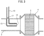
- FIG. 3 shows a modification of the hydrogen supply pipe 13.
- a plurality of heat exchange fins 15 for heat exchange with the exhaust gas flowing through the inside of the exhaust pipe 3 are formed on the outer circumferential surface of the hydrogen supply pipe 13 positioned at the inside of the exhaust pipe 3.
- heat exchange fins are not formed on the inner circumferential surface of the hydrogen supply pipe 13 positioned inside the exhaust pipe 3. Instead of this, in the example shown in FIG.
- a swirl flow generator 17 for imparting a swirl flow around the axis of the hydrogen supply pipe 13 to the hydrogen flowing through the inside of the hydrogen supply pipe 13, more accurately to the reformed gas containing hydrogen, is arranged at a position inside the hydrogen supply pipe 13 and outside of the exhaust pipe 3.
- FIG. 4A and FIG. 4B show another modification of the hydrogen supply pipe 13.
- the front end part of the hydrogen supply pipe 13 extends inside of the exhaust pipe 3 in a vortex shape around the axis of the exhaust pipe 3 up to the axis of the exhaust pipe 3 and the front end opening part 14 of the hydrogen supply pipe 13 is oriented toward the upstream side end face of the exhaust treatment catalyst 5.
- a plurality of heat exchange fins 15 for heat exchange with the exhaust gas flowing through the inside of the exhaust pipe 3 are formed on the outer circumferential surface of the hydrogen supply pipe 13 positioned at the inside of the exhaust pipe 3.
- These heat exchange fins 15 are comprised of thin fins extending in the direction of flow of the exhaust gas inside the exhaust pipe 3.
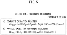
- FIGS. 5(a) and (b) show the reaction formula when a complete oxidation reaction is performed and the reaction formula when a partial oxidation reform reaction is performed in the case of using the generally used diesel fuel as fuel. Note that, the amounts of heat generated ⁇ H 0 in the reaction formulas are shown by the lower heating value (LHV).
- LHV lower heating value
- This partial oxidation reform reaction is performed by a rich air-fuel ratio of an O 2 /C molar ratio 0.5 indicating the ratio of the air and fuel which are made to react. At this time, CO and H 2 are formed.
- substantially 830°C reformed gas flows out from the reforming catalyst 7 to the inside of the reformed gas outflow chamber 9 and the reformed gas flowing out to the inside of the reformed gas outflow chamber 9 is sent through the hydrogen supply pipe 13 to the inside of the exhaust pipe 3.
- the actual equilibrium reaction temperature TB at this time is somewhat lower than 830°C, therefore, actually, the temperature of the reformed gas flowing out to the inside of the reformed gas outflow chamber 9 is somewhat lower than 830°C.
- the ratio of the air and fuel when the O 2 /C molar ratio 1.4575 becomes the stoichiometric air-fuel ratio.
- the reaction equilibrium temperature TB becomes the highest when the ratio of the air and fuel becomes the stoichiometric air-fuel ratio.
- the larger the O 2 /C molar ratio the larger the ratio by which the complete oxidation reaction is performed compared with the ratio by which the partial oxidation reform reaction is performed, so the larger the O 2 /C molar ratio, the higher the reaction equilibrium temperature TB.
- FIG. 6B shows the relationship between the number of molecules (H 2 and CO) formed per atom of carbon and the O 2 /C molar ratio.
- the larger the O 2 /C molar ratio than 0.5 the smaller the ratio by which the partial oxidation reform reaction is performed. Therefore, as shown in FIG. 6B , the greater the O 2 /C molar ratio than 0.5, the smaller the amounts of formation of H 2 and CO.
- the equilibrium reaction temperature TB rapidly rises and the temperature of the reforming catalyst 7 also rapidly rises.
- the reforming catalyst 7 ends up deteriorating due to heat.
- the excess carbon C not able to be reacted with increases. This excess carbon C deposits inside the pores of the substrate of the reforming catalyst 7 to cause so-called "coking". If coking occurs, the reform ability of the reforming catalyst 7 remarkably falls. Therefore, to avoid the occurrence of coking, the O 2 /C molar ratio has to be kept from becoming smaller than 0.5.
- the O 2 /C molar ratio when the O 2 /C molar ratio is 0.5, the amount of formation of hydrogen becomes the largest in the range where no excess carbon C is formed. Therefore, when performing the partial oxidation reform reaction for forming hydrogen, to avoid coking and heat deterioration of the reforming catalyst 7 while enabling the most efficient formation of hydrogen, the O 2 /C molar ratio is made 0.5 or slightly higher than 0.5. The reformed gas containing hydrogen formed at this time falls somewhat in temperature up to reaching the exhaust pipe 3 and becomes 700°C to 920°C or so.
- the exhaust treatment catalyst 5 is comprised of an oxidation catalyst, NO X storage catalyst, or catalyst-equipped particulate filter.
- This exhaust treatment catalyst 5 carries a precious metal catalyst such as platinum Pt, palladium Pd, or rhodium Rh. If in this way the exhaust treatment catalyst 5 carries a precious metal catalyst, the hydrogen contained in the reformed gas supplied from the hydrogen supply pipe 13 will be made to react with oxygen on the precious metal catalyst, and the exhaust treatment catalyst 5 will further rise in temperature due to the heat of oxidation reaction generated at this time.
- a precious metal catalyst such as platinum Pt, palladium Pd, or rhodium Rh.
- the exhaust gas pressure inside the exhaust pipe 3 upstream of the exhaust treatment catalyst 5 is substantially atmospheric pressure. Therefore, when hydrogen is supplied from the hydrogen supply pipe 13 to the inside of the exhaust pipe 3, if the ambient air temperature is about 550°C or more, this hydrogen will be consumed by self ignition.
- a plurality of heat exchange fins 15 for heat exchange with exhaust gas flowing through the inside of the exhaust pipe 3 are formed on at least the outer circumferential surface of the hydrogen supply pipe 13 positioned inside the exhaust pipe 3. If in this way a plurality of heat exchange fins 15 are formed on the outer circumferential surface of the hydrogen supply pipe 13, due to the heat exchange action with the exhaust gas, which is lower in temperature than the temperature of the hydrogen flowing through the hydrogen supply pipe 13, the temperature of the hydrogen flowing through the hydrogen supply pipe 13 is made to fall so that the temperature around the hydrogen supplied from the hydrogen supply pipe 13 to the inside of the exhaust gas, that is, the ambient air temperature, becomes about 550°C or less.
- the hydrogen supplied from the hydrogen supply pipe 13 to the exhaust pipe 3 will be sent into the exhaust treatment catalyst 5 without being consumed by self ignition, and the temperature of the exhaust treatment catalyst 5 is made to rapidly rise due to the heat of oxidation reaction of the hydrogen generated in the exhaust treatment catalyst 5.
- the exhaust gas flowing around the hydrogen supply pipe 13 is heated by the heat exchange action with the hydrogen flowing through the hydrogen supply pipe 13 and rises in temperature.
- This raised temperature exhaust gas flows into the exhaust treatment catalyst 5 whereby the temperature of the exhaust treatment catalyst 5 is made to further rise. That is, the amount of heat used for cooling the hydrogen flowing through the inside of the hydrogen supply pipe 13 can be effectively utilized for raising the temperature of the exhaust treatment catalyst 5.
- the cooling action of the hydrogen flowing through the hydrogen supply pipe 13 is further promoted by formation of the heat exchange fins 15 over the entire outer circumferential surface of the hydrogen supply pipe 13 and, as shown in FIG. 2A and FIG. 2B , is further promoted by formation of a plurality of the heat exchange fins 16 over the inner circumferential surface of the hydrogen supply pipe 13 positioned inside of the exhaust pipe 3.
- the swirl flow generator 17 is arranged inside the hydrogen supply pipe 13 positioned at the outside side part of the exhaust pipe 3, that is, at the entrance of the hydrogen supply pipe 13 to the inside of the exhaust pipe 3. Due to this swirl flow generator 17, a swirl flow about the axis of the hydrogen supply pipe 13 is imparted to the reformed gas containing hydrogen flowing through the hydrogen supply pipe 13. As a result, heat exchange between the hydrogen flowing through the hydrogen supply pipe 13 and the exhaust gas is promoted and the cooling action of the hydrogen flowing through the hydrogen supply pipe 13 is promoted. Further, in the modification shown in FIG. 4A and FIG. 4B , the contact area of the hydrogen supply pipe 13 with the exhaust gas is increased and the heat exchange time with the exhaust gas is also increased, so the cooling action of the hydrogen flowing through the hydrogen supply pipe 13 is further promoted.
Landscapes
- Chemical & Material Sciences (AREA)
- Engineering & Computer Science (AREA)
- Chemical Kinetics & Catalysis (AREA)
- Combustion & Propulsion (AREA)
- Health & Medical Sciences (AREA)
- Mechanical Engineering (AREA)
- General Engineering & Computer Science (AREA)
- Toxicology (AREA)
- Organic Chemistry (AREA)
- General Health & Medical Sciences (AREA)
- Inorganic Chemistry (AREA)
- Biomedical Technology (AREA)
- Environmental & Geological Engineering (AREA)
- Analytical Chemistry (AREA)
- General Chemical & Material Sciences (AREA)
- Oil, Petroleum & Natural Gas (AREA)
- Exhaust Gas After Treatment (AREA)
- Exhaust Gas Treatment By Means Of Catalyst (AREA)
Abstract
Description
- The present invention relates to an exhaust purification system of an internal combustion engine.
- Known in the past has been an internal combustion engine in which an NOX purification catalyst is arranged in an engine exhaust passage, a fuel reforming device for generating reformed gas containing hydrogen is provided, high temperature reformed gas containing hydrogen produced in the fuel reforming device is fed to the engine exhaust passage upstream of the NOx purification catalyst at the time of engine start, and the hydrogen in the supplied reformed gas is used to raise the NOX purification rate of the NOX purification catalyst (for example, see Japanese Unexamined Patent Publication No.
2010-270664 - In this regard, in the case of arranging an exhaust treatment catalyst like an oxidation catalyst in an engine exhaust passage, supplying high temperature reformed gas containing hydrogen generated in a fuel reforming device to the inside of the engine exhaust passage upstream of the exhaust treatment catalyst, and trying to make the temperature of the exhaust treatment catalyst rapidly rise by the heat of oxidation reaction of the hydrogen on the exhaust treatment catalyst, if the hydrogen supplied to the inside of the engine exhaust passage ends up reacting with the oxygen contained in the exhaust gas and will be consumed by self igniting before reacting with oxygen on the exhaust treatment catalyst, no heat of oxidation reaction of hydrogen will be generated any longer on the exhaust treatment catalyst and it will become difficult to make the temperature of the exhaust treatment catalyst rapidly rise.
- In this case, to make the temperature of the exhaust treatment catalyst rapidly rise, it is necessary to keep the hydrogen supplied to the inside of the engine exhaust passage from reacting with oxygen contained in the exhaust gas and being consumed by self igniting before reacting with oxygen on the exhaust treatment catalyst. However, in the above-mentioned internal combustion engine, this was not considered at all.
- According to the present invention, there is provided an exhaust purification system of an internal combustion engine comprising: a reformer, an exhaust treatment catalyst arranged in an engine exhaust passage, a hydrogen supply pipe inserted inside the engine exhaust passage upstream of the exhaust treatment catalyst, hydrogen generated in the reformer being supplied to the engine exhaust passage upstream of the exhaust treatment catalyst via the hydrogen supply pipe, and heat exchange fins formed on an outer circumferential surface of the hydrogen supply pipe for heat exchange with exhaust gas flowing through an inside of the engine exhaust passage.
- By forming heat exchange fins for heat exchange with exhaust gas on the outer circumferential surface of the hydrogen supply pipe, the temperature of the reformed gas falls. Due to this, hydrogen contained in the reformed gas is kept from being consumed by self igniting, so it is possible to make the temperature of the exhaust treatment catalyst rapidly rise. Furthermore, by forming heat exchange fins on the outer circumferential surface of the hydrogen supply pipe, the heat of the reformed gas is efficiently transmitted to the exhaust gas. As a result, the temperature of the exhaust gas rises and accordingly a rise in temperature of the exhaust treatment catalyst is promoted.
-
-
FIG. 1 is an overall view of an internal combustion engine. -
FIG. 2A and FIG. 2B are respectively an enlarged cross-sectional side view of the surroundings of an exhaust treatment device inFIG. 1 and a cross-sectional view along a cross-section B-B inFIG. 2A . -
FIG. 3 is an enlarged cross-sectional side view of the surroundings of an exhaust treatment device showing another embodiment. -
FIG. 4A and FIG. 4B are respectively an enlarged cross-sectional side view of the surroundings of an exhaust treatment device showing still another embodiment and a cross-sectional view along a cross-section B-B inFIG. 4A . -
FIG. 5 is a view for explaining a reform reaction of diesel fuel. -
FIG. 6A and FIG. 6B are respectively a view showing a relationship between a reaction equilibrium temperature TB and an O2/C molar ratio and a view showing a relationship between a number of molecules formed per atom of carbon and an O2/C molar ratio. -
FIG. 7 is a view showing a region where hydrogen will be consumed by self ignition. -
FIG. 1 is an overall view of a compression ignition type internal combustion engine. Referring toFIG. 1, 1 indicates an engine body, 2 an exhaust manifold, 3 an exhaust pipe, 4 an exhaust treatment device connected to theexhaust pipe exhaust treatment device 4, and 6 a reformer for forming reformed gas containing hydrogen. Thereformer 6 is provided with a reformingcatalyst 7, aburner combustion chamber 8 formed at one side of the reformingcatalyst 7, a reformedgas outflow chamber 9 formed at the other side of the reformingcatalyst 7, and aburner 10. Theburner 10 is connected to afuel tank 11 and anair pump 12. Fuel supplied from thefuel tank 11 and air supplied from theair pump 12 are supplied from theburner 10 to the inside of theburner combustion chamber 8. - The fuel supplied from the
burner 10 is made to burn inside theburner combustion chamber 8. Next, the produced combustion gas is sent into the reformingcatalyst 7 and reformed whereby reformed gas containing hydrogen is produced in the reformingcatalyst 7. The reformed gas containing hydrogen produced at the reformingcatalyst 7 is sent into the reformedgas outflow chamber 9. The reformed gas containing hydrogen sent into the reformedgas outflow chamber 9 is supplied through ahydrogen supply pipe 13 extending from the reformedgas outflow chamber 9 to the inside of theexhaust pipe 3, to the inside of theexhaust pipe 3 upstream of theexhaust treatment catalyst 5, that is, to the inside of the engine exhaust passage upstream of theexhaust treatment catalyst 5. Thisexhaust treatment catalyst 5 is comprised of an oxidation catalyst, NOX storage catalyst, or catalyst-equipped particulate filter. -
FIG. 2A is an enlarged cross-sectional side view of the surroundings of theexhaust treatment device 4 shown inFIG. 1 . Referring toFIG. 2A , thehydrogen supply pipe 13 is comprised of a hollow metal pipe. The front end part of thishydrogen supply pipe 13 extends from an outside of theexhaust pipe 3 through a wall of theexhaust pipe 3 to an inside of theexhaust pipe 3. The front end part of thehydrogen supply part 13 is bent at the center part at the inside of theexhaust pipe 3 in the axial direction of theexhaust pipe 3 so that the frontend opening part 14 of thehydrogen supply pipe 13 faces the upstream side end face of theexhaust treatment catalyst 5. Note that, in the example shown inFIG. 2A , the front end part of thehydrogen supply pipe 13 forms an L-shape inside theexhaust pipe 3. - On the other hand, as shown in
FIG. 2A and FIG. 2B , a plurality of heat exchange fins 15 for heat exchange with the exhaust gas flowing through the inside of theexhaust pipe 3 are formed on the outer circumferential surface of thehydrogen supply pipe 13 positioned inside theexhaust pipe 3. In other words, a plurality of heat exchange fins 15 for heat exchange with the exhaust gas flowing through the inside of the engine exhaust passage are formed on the outer circumferential surface of thehydrogen supply pipe 13 inserted inside the engine exhaust passage. As will be understood fromFIG. 2A and FIG. 2B , theseheat exchange fins 15 are comprised of thin fins extending in the direction of flow of exhaust gas at the inside of theexhaust pipe 3. Further, in the example shown inFIG. 2A and FIG. 2B ,heat exchange fins 15 are formed over the entire outer circumferential surface of thehydrogen supply pipe 13 positioned inside theexhaust pipe 3. - On the other hand, in the example shown in
FIG. 2A and FIG. 2B , a plurality of heat exchange fins 16 for heat exchange with the hydrogen flowing through the inside of thehydrogen supply pipe 13, more accurately for heat exchange with the reformed gas containing hydrogen, are also formed on the inner circumferential surface of thehydrogen supply pipe 13 positioned inside theexhaust pipe 3. Note that, in the example shown inFIG. 2A and FIG. 2B , theseheat exchange fins 16 are formed in thehydrogen supply pipe 13 positioned inside theexhaust pipe 3 only at the part extending along the axial line of theexhaust pipe 3. -
FIG. 3 shows a modification of thehydrogen supply pipe 13. In the example shown inFIG. 3 , in the same way as the example shown inFIG. 2A and FIG. 2B , a plurality ofheat exchange fins 15 for heat exchange with the exhaust gas flowing through the inside of theexhaust pipe 3 are formed on the outer circumferential surface of thehydrogen supply pipe 13 positioned at the inside of theexhaust pipe 3. As opposed to this, in the example shown inFIG. 3 , unlike the example shown inFIG. 2A and FIG. 2B , heat exchange fins are not formed on the inner circumferential surface of thehydrogen supply pipe 13 positioned inside theexhaust pipe 3. Instead of this, in the example shown inFIG. 3 , aswirl flow generator 17 for imparting a swirl flow around the axis of thehydrogen supply pipe 13 to the hydrogen flowing through the inside of thehydrogen supply pipe 13, more accurately to the reformed gas containing hydrogen, is arranged at a position inside thehydrogen supply pipe 13 and outside of theexhaust pipe 3. -
FIG. 4A and FIG. 4B show another modification of thehydrogen supply pipe 13. In the example shown inFIG. 4A and FIG. 4B , the front end part of thehydrogen supply pipe 13 extends inside of theexhaust pipe 3 in a vortex shape around the axis of theexhaust pipe 3 up to the axis of theexhaust pipe 3 and the frontend opening part 14 of thehydrogen supply pipe 13 is oriented toward the upstream side end face of theexhaust treatment catalyst 5. In this modification as well, as shown inFIG. 4A and FIG. 4B , a plurality ofheat exchange fins 15 for heat exchange with the exhaust gas flowing through the inside of theexhaust pipe 3 are formed on the outer circumferential surface of thehydrogen supply pipe 13 positioned at the inside of theexhaust pipe 3. Theseheat exchange fins 15 are comprised of thin fins extending in the direction of flow of the exhaust gas inside theexhaust pipe 3. - As explained above, in the
reformer 6, hydrogen is formed by reforming the fuel. Therefore, next, referring toFIG. 5 , the reform reaction in the case of using diesel fuel as fuel will be simply explained.FIGS. 5(a) and (b) show the reaction formula when a complete oxidation reaction is performed and the reaction formula when a partial oxidation reform reaction is performed in the case of using the generally used diesel fuel as fuel. Note that, the amounts of heat generated ΔH0 in the reaction formulas are shown by the lower heating value (LHV). In thereformer 6 shown inFIG. 1 , the fuel and air supplied from theburner 10 react at the reformingcatalyst 7 by the partial oxidation reform reaction shown inFIG. 5(b) whereby hydrogen is formed. This partial oxidation reform reaction, as shown by the reaction formula of the partial oxidation reform reaction ofFIG. 5(b) , is performed by a rich air-fuel ratio of an O2/C molar ratio 0.5 indicating the ratio of the air and fuel which are made to react. At this time, CO and H2 are formed. -
FIG. 6A shows the relationship between the reaction equilibrium temperature TB when the air and fuel are made to react at the reformingcatalyst 7 and reach an equilibrium and the O2/C molar ratio of the air and fuel. Note that, the solid line ofFIG. 6A shows the theoretical value when the air temperature is 25°C. As shown by the solid line ofFIG. 6A , when the partial oxidation reform reaction is performed by a rich air-fuel ratio of an O2/C molar ratio=0.5, the equilibrium reaction temperature TB becomes about 830°C. At this time, substantially 830°C reformed gas flows out from the reformingcatalyst 7 to the inside of the reformedgas outflow chamber 9 and the reformed gas flowing out to the inside of the reformedgas outflow chamber 9 is sent through thehydrogen supply pipe 13 to the inside of theexhaust pipe 3. Note that, the actual equilibrium reaction temperature TB at this time is somewhat lower than 830°C, therefore, actually, the temperature of the reformed gas flowing out to the inside of the reformedgas outflow chamber 9 is somewhat lower than 830°C. - On the other hand, as will be understood from the reaction formula of the complete oxidation reaction of
FIG. 5(a) , the ratio of the air and fuel when the O2/C molar ratio=1.4575 becomes the stoichiometric air-fuel ratio. As shown inFIG. 6A , the reaction equilibrium temperature TB becomes the highest when the ratio of the air and fuel becomes the stoichiometric air-fuel ratio. When the O2/C molar ratio is between 0.5 and 1.4575, in part, the partial oxidation reform reaction is performed, while in part, the complete oxidation reaction is performed. In this case, the larger the O2/C molar ratio, the larger the ratio by which the complete oxidation reaction is performed compared with the ratio by which the partial oxidation reform reaction is performed, so the larger the O2/C molar ratio, the higher the reaction equilibrium temperature TB. - On the other hand,
FIG. 6B shows the relationship between the number of molecules (H2 and CO) formed per atom of carbon and the O2/C molar ratio. As explained above, the larger the O2/C molar ratio than 0.5, the smaller the ratio by which the partial oxidation reform reaction is performed. Therefore, as shown inFIG. 6B , the greater the O2/C molar ratio than 0.5, the smaller the amounts of formation of H2 and CO. Further, as shown inFIG. 6A , if the O2/C molar ratio becomes larger than 0.5, the equilibrium reaction temperature TB rapidly rises and the temperature of the reformingcatalyst 7 also rapidly rises. Therefore, if making the O2/C molar ratio larger than 0.5, the reformingcatalyst 7 ends up deteriorating due to heat. On the other hand, as shown inFIG. 6B , if the O2/C molar ratio becomes smaller than 0.5, the excess carbon C not able to be reacted with increases. This excess carbon C deposits inside the pores of the substrate of the reformingcatalyst 7 to cause so-called "coking". If coking occurs, the reform ability of the reformingcatalyst 7 remarkably falls. Therefore, to avoid the occurrence of coking, the O2/C molar ratio has to be kept from becoming smaller than 0.5. - Further, as will be understood from
FIG. 6B , when the O2/C molar ratio is 0.5, the amount of formation of hydrogen becomes the largest in the range where no excess carbon C is formed. Therefore, when performing the partial oxidation reform reaction for forming hydrogen, to avoid coking and heat deterioration of the reformingcatalyst 7 while enabling the most efficient formation of hydrogen, the O2/C molar ratio is made 0.5 or slightly higher than 0.5. The reformed gas containing hydrogen formed at this time falls somewhat in temperature up to reaching theexhaust pipe 3 and becomes 700°C to 920°C or so. - Next, for example, the case of making the temperature of the
exhaust treatment catalyst 5 rise when, like at the time of engine warm-up operation, the temperature of theexhaust treatment catalyst 5 is low will be explained. Now then, when the temperature of theexhaust treatment catalyst 5 is low, if high temperature reformed gas containing hydrogen is supplied from thehydrogen supply pipe 13, theexhaust treatment catalyst 5 is heated by not only the heat of the exhaust gas, but also the heat of the supplied reformed gas and rises in temperature. At this time, theexhaust treatment catalyst 5 rises in temperature due to the heat of exhaust gas and heat of reformed gas transferred by heat transfer to theexhaust treatment catalyst 5. On the other hand, as explained above, theexhaust treatment catalyst 5 is comprised of an oxidation catalyst, NOX storage catalyst, or catalyst-equipped particulate filter. Thisexhaust treatment catalyst 5 carries a precious metal catalyst such as platinum Pt, palladium Pd, or rhodium Rh. If in this way theexhaust treatment catalyst 5 carries a precious metal catalyst, the hydrogen contained in the reformed gas supplied from thehydrogen supply pipe 13 will be made to react with oxygen on the precious metal catalyst, and theexhaust treatment catalyst 5 will further rise in temperature due to the heat of oxidation reaction generated at this time. - In this regard, when the
exhaust treatment catalyst 5 is heated by the heat of oxidation reaction of hydrogen in this way, theexhaust treatment catalyst 5 itself is directly heated by the heat of oxidation reaction of hydrogen. Therefore, if theexhaust treatment catalyst 5 is heated by the heat of oxidation reaction of hydrogen, the temperature of theexhaust treatment catalyst 5 is made to rise far more rapidly compared with the case where theexhaust treatment catalyst 5 is heated due to heat transfer of the heat of exhaust gas and heat of reformed gas. Therefore, to make the temperature of theexhaust treatment catalyst 5 rise, utilizing the heat of oxidation reaction of hydrogen is extremely effective. For this reason, it is necessary to send as much hydrogen as possible from thehydrogen supply pipe 13 to the inside of theexhaust treatment catalyst 5. - In this regard, hydrogen reacts with oxygen (2H2+O2→2H2O) and is consumed by self ignition if there is oxygen present in the surroundings and the temperature of the surroundings becomes high. The hatched region of
FIG. 7 shows the region where hydrogen reacts with oxygen and hydrogen is consumed by self ignition in this way. Note that, inFIG. 7 , the abscissa shows the temperature around the hydrogen, that is, the ambient air temperature (°C), while the ordinate shows the pressure (mmHg). Further, inFIG. 7 , the broken line shows the atmospheric pressure. Therefore, fromFIG. 7 , it will be understood that if the ambient air temperature becomes 550°C or more, hydrogen will be consumed by self ignition. On the other hand, the exhaust gas pressure inside theexhaust pipe 3 upstream of theexhaust treatment catalyst 5 is substantially atmospheric pressure. Therefore, when hydrogen is supplied from thehydrogen supply pipe 13 to the inside of theexhaust pipe 3, if the ambient air temperature is about 550°C or more, this hydrogen will be consumed by self ignition. - Now then, to send as much hydrogen as possible from the
hydrogen supply pipe 13 to the inside of theexhaust treatment catalyst 5, it is necessary to make the hydrogen supplied from thehydrogen supply pipe 13 to the inside of theexhaust pipe 3 reach theexhaust treatment catalyst 5 without being consumed by self ignition. For this, when hydrogen is supplied from thehydrogen supply pipe 13 to the inside of theexhaust pipe 3, the temperature around the supplied hydrogen, that is, the ambient air temperature, has to be made to decrease to about 550°C or less. On the other hand, as explained above, the reformed gas containing hydrogen formed at thereformer 6 becomes 700°C to 920°C or so around when reaching theexhaust pipe 3. Therefore, in order to send as much hydrogen as possible from thehydrogen supply pipe 13 to the inside of theexhaust treatment catalyst 5, it is necessary to lower the temperature of the hydrogen, which is 700°C to 920°C or so while hydrogen is flowing through thehydrogen supply pipe 13, so that the temperature around the hydrogen supplied from thehydrogen supply pipe 13, that is, the ambient air temperature, becomes about 550°C or less. - Therefore, in an embodiment according to the present invention, a plurality of
heat exchange fins 15 for heat exchange with exhaust gas flowing through the inside of theexhaust pipe 3 are formed on at least the outer circumferential surface of thehydrogen supply pipe 13 positioned inside theexhaust pipe 3. If in this way a plurality ofheat exchange fins 15 are formed on the outer circumferential surface of thehydrogen supply pipe 13, due to the heat exchange action with the exhaust gas, which is lower in temperature than the temperature of the hydrogen flowing through thehydrogen supply pipe 13, the temperature of the hydrogen flowing through thehydrogen supply pipe 13 is made to fall so that the temperature around the hydrogen supplied from thehydrogen supply pipe 13 to the inside of the exhaust gas, that is, the ambient air temperature, becomes about 550°C or less. As a result, the hydrogen supplied from thehydrogen supply pipe 13 to theexhaust pipe 3 will be sent into theexhaust treatment catalyst 5 without being consumed by self ignition, and the temperature of theexhaust treatment catalyst 5 is made to rapidly rise due to the heat of oxidation reaction of the hydrogen generated in theexhaust treatment catalyst 5. - On the other hand, the exhaust gas flowing around the
hydrogen supply pipe 13 is heated by the heat exchange action with the hydrogen flowing through thehydrogen supply pipe 13 and rises in temperature. This raised temperature exhaust gas flows into theexhaust treatment catalyst 5 whereby the temperature of theexhaust treatment catalyst 5 is made to further rise. That is, the amount of heat used for cooling the hydrogen flowing through the inside of thehydrogen supply pipe 13 can be effectively utilized for raising the temperature of theexhaust treatment catalyst 5. Note that, the cooling action of the hydrogen flowing through thehydrogen supply pipe 13 is further promoted by formation of theheat exchange fins 15 over the entire outer circumferential surface of thehydrogen supply pipe 13 and, as shown inFIG. 2A and FIG. 2B , is further promoted by formation of a plurality of theheat exchange fins 16 over the inner circumferential surface of thehydrogen supply pipe 13 positioned inside of theexhaust pipe 3. - In the modification shown in
FIG. 3 , theswirl flow generator 17 is arranged inside thehydrogen supply pipe 13 positioned at the outside side part of theexhaust pipe 3, that is, at the entrance of thehydrogen supply pipe 13 to the inside of theexhaust pipe 3. Due to thisswirl flow generator 17, a swirl flow about the axis of thehydrogen supply pipe 13 is imparted to the reformed gas containing hydrogen flowing through thehydrogen supply pipe 13. As a result, heat exchange between the hydrogen flowing through thehydrogen supply pipe 13 and the exhaust gas is promoted and the cooling action of the hydrogen flowing through thehydrogen supply pipe 13 is promoted. Further, in the modification shown inFIG. 4A and FIG. 4B , the contact area of thehydrogen supply pipe 13 with the exhaust gas is increased and the heat exchange time with the exhaust gas is also increased, so the cooling action of the hydrogen flowing through thehydrogen supply pipe 13 is further promoted.
Claims (4)
- An exhaust purification system of an internal combustion engine comprising:a reformer,an exhaust treatment catalyst arranged in an engine exhaust passage,a hydrogen supply pipe inserted inside the engine exhaust passage upstream of the exhaust treatment catalyst, hydrogen generated in the reformer being supplied to the engine exhaust passage upstream of the exhaust treatment catalyst via the hydrogen supply pipe, andheat exchange fins formed on an outer circumferential surface of the hydrogen supply pipe for heat exchange with exhaust gas flowing through an inside of the engine exhaust passage.
- The exhaust purification system of an internal combustion engine according to claim 1, wherein heat exchange fins for heat exchange with reformed gas containing hydrogen and flowing through the inside of the hydrogen supply pipe are further formed on an inner circumferential surface of the hydrogen supply pipe.
- The exhaust purification system of an internal combustion engine according to claim 1, wherein a swirl flow generator imparting a swirl flow about an axis of the hydrogen supply pipe to reformed gas containing hydrogen flowing through the inside of the hydrogen supply pipe is arranged inside of the hydrogen supply pipe.
- The exhaust purification system of an internal combustion engine according to claim 1, wherein a front end part of the hydrogen supply pipe extends from outside of an exhaust pipe through a wall of the exhaust pipe to the inside of the exhaust pipe and is bent in an axial direction of the exhaust pipe so that an opening part of the front end of the hydrogen supply pipe faces an upstream side end face of the exhaust treatment catalyst.
Applications Claiming Priority (1)
| Application Number | Priority Date | Filing Date | Title |
|---|---|---|---|
| JP2018076170A JP6958464B2 (en) | 2018-04-11 | 2018-04-11 | Exhaust purification device for internal combustion engine |
Publications (1)
| Publication Number | Publication Date |
|---|---|
| EP3553288A1 true EP3553288A1 (en) | 2019-10-16 |
Family
ID=65493924
Family Applications (1)
| Application Number | Title | Priority Date | Filing Date |
|---|---|---|---|
| EP19157764.2A Withdrawn EP3553288A1 (en) | 2018-04-11 | 2019-02-18 | Exhaust purification system of an internal combustion engine |
Country Status (7)
| Country | Link |
|---|---|
| US (1) | US10641150B2 (en) |
| EP (1) | EP3553288A1 (en) |
| JP (1) | JP6958464B2 (en) |
| KR (1) | KR20190118969A (en) |
| CN (1) | CN110359986A (en) |
| BR (1) | BR102019003151A2 (en) |
| RU (1) | RU2703792C1 (en) |
Families Citing this family (1)
| Publication number | Priority date | Publication date | Assignee | Title |
|---|---|---|---|---|
| JP7816040B2 (en) * | 2022-08-12 | 2026-02-18 | 株式会社豊田自動織機 | Ammonia Engine System |
Citations (7)
| Publication number | Priority date | Publication date | Assignee | Title |
|---|---|---|---|---|
| EP0537968A1 (en) * | 1991-10-16 | 1993-04-21 | Toyota Jidosha Kabushiki Kaisha | Nitrogen oxides decreasing apparatus for an internal combustion engine |
| EP0784741A1 (en) * | 1994-10-07 | 1997-07-23 | THE TEXAS A&M UNIVERSITY SYSTEM | Method and apparatus for heating a catalytic converter to reduce emissions |
| JP2921158B2 (en) * | 1991-04-17 | 1999-07-19 | トヨタ自動車株式会社 | Exhaust gas purification device for internal combustion engine |
| JP2010270664A (en) | 2009-05-21 | 2010-12-02 | Honda Motor Co Ltd | Exhaust gas purification system for internal combustion engine |
| DE102014117687A1 (en) * | 2013-12-03 | 2015-06-18 | Faurecia Systemes D'echappement | Device for injecting a reducing agent and corresponding exhaust line |
| DE102016107867A1 (en) * | 2015-05-12 | 2016-11-17 | Denso Corporation | Exhaust emission control system and purification control device |
| DE102016100284A1 (en) * | 2016-01-11 | 2017-07-13 | Eberspächer Exhaust Technology GmbH & Co. KG | Exhaust system for an internal combustion engine and method for operating an exhaust system |
Family Cites Families (32)
| Publication number | Priority date | Publication date | Assignee | Title |
|---|---|---|---|---|
| JP2910468B2 (en) * | 1992-12-09 | 1999-06-23 | トヨタ自動車株式会社 | Catalyst warm-up device for internal combustion engine |
| US5845485A (en) * | 1996-07-16 | 1998-12-08 | Lynntech, Inc. | Method and apparatus for injecting hydrogen into a catalytic converter |
| RU2131980C1 (en) * | 1997-08-21 | 1999-06-20 | Воропанова Лидия Алексеевна | Exhaust gas catalyst converter of internal combustion engine |
| JP3733753B2 (en) * | 1998-07-29 | 2006-01-11 | 松下電器産業株式会社 | Hydrogen purification equipment |
| US6122909A (en) * | 1998-09-29 | 2000-09-26 | Lynntech, Inc. | Catalytic reduction of emissions from internal combustion engines |
| DE19855338A1 (en) * | 1998-12-01 | 2000-06-08 | Bosch Gmbh Robert | Device for introducing a reducing agent into an exhaust pipe section of an internal combustion engine |
| EP1194213B1 (en) * | 1999-01-22 | 2011-11-02 | Benteler Automotive Corporation | Vacuum-insulated exhaust treatment device with phase change materials and thermal management systems. |
| RU2159344C1 (en) * | 1999-06-21 | 2000-11-20 | Институт структурной макрокинетики и проблем материаловедения РАН | Method of cleaning exhaust gases of internal combustion engine |
| DE19934413A1 (en) * | 1999-07-22 | 2001-01-25 | Siemens Ag | Apparatus for introducing an additive into an exhaust gas in the exhaust gas line of a diesel engine comprises a nozzle and mixers which are combined to form a constructive and functional component |
| US6272849B1 (en) * | 2000-01-13 | 2001-08-14 | Ford Global Technologies, Inc. | Apparatus and method for heating an automotive catalyst to an emission reactive condition |
| US6738930B1 (en) * | 2000-12-22 | 2004-05-18 | Crystal Group Inc. | Method and system for extending the functionality of an environmental monitor for an industrial personal computer |
| DE10202171A1 (en) * | 2002-01-22 | 2003-07-31 | Bayerische Motoren Werke Ag | Motor vehicle with a cryogenic tank |
| US7021048B2 (en) * | 2002-01-25 | 2006-04-04 | Arvin Technologies, Inc. | Combination emission abatement assembly and method of operating the same |
| US7614213B2 (en) * | 2003-09-19 | 2009-11-10 | Nissan Diesel Motor Co., Ltd. | Engine exhaust emission purification apparatus |
| SE528119C2 (en) * | 2004-08-06 | 2006-09-05 | Scania Cv Ab | Arrangement for supplying a medium to an exhaust line of an internal combustion engine |
| US7581387B2 (en) | 2005-02-28 | 2009-09-01 | Caterpillar Inc. | Exhaust gas mixing system |
| KR100675957B1 (en) * | 2005-10-04 | 2007-02-02 | 한국에너지기술연구원 | Internal combustion engine exhaust gas heater |
| US20070144158A1 (en) * | 2005-12-22 | 2007-06-28 | Girard James W | Exhaust dispersion device |
| JP4928304B2 (en) * | 2007-02-23 | 2012-05-09 | 日野自動車株式会社 | Exhaust purification device |
| JP5244334B2 (en) * | 2007-05-01 | 2013-07-24 | 三菱ふそうトラック・バス株式会社 | Exhaust gas purification device for internal combustion engine |
| EP2014886A1 (en) * | 2007-07-09 | 2009-01-14 | Delphi Technologies, Inc. | Reservoir for a fluid dosing system |
| ES2481447T3 (en) * | 2008-01-10 | 2014-07-30 | Haldor Topsoe A/S | Method and system for the purification of diesel engine exhaust gas |
| DE102008044708A1 (en) * | 2008-08-28 | 2010-03-04 | Emitec Gesellschaft Für Emissionstechnologie Mbh | SCR system with compensation element |
| JP2010203335A (en) * | 2009-03-04 | 2010-09-16 | Nissan Motor Co Ltd | Exhaust emission control device |
| DE102009032022A1 (en) * | 2009-07-07 | 2011-01-13 | Man Nutzfahrzeuge Aktiengesellschaft | Method and device for the regeneration of a particulate filter arranged in the exhaust tract of an internal combustion engine |
| JP2013503284A (en) * | 2009-08-28 | 2013-01-31 | ユミコア・アクチエンゲゼルシャフト・ウント・コムパニー・コマンディットゲゼルシャフト | Exhaust gas aftertreatment system with catalytically active wall flow filter with storage function upstream of a catalytic converter with the same storage function |
| WO2011114498A1 (en) * | 2010-03-15 | 2011-09-22 | トヨタ自動車株式会社 | Exhaust gas purification device for internal combustion engine |
| EP3267005B2 (en) * | 2010-06-22 | 2023-12-27 | Donaldson Company, Inc. | Exhaust aftertreatment device |
| EP2778382A4 (en) * | 2011-09-14 | 2015-09-09 | Hino Motors Ltd | Fuel reformer and exhaust gas purification device using same |
| CN205714365U (en) * | 2016-04-08 | 2016-11-23 | 江西省太平洋节能环保科技有限公司 | A kind of second-time burning purifying processing device |
| JP2018003654A (en) * | 2016-06-29 | 2018-01-11 | 株式会社Soken | Modified reductant supply device |
| JP6443404B2 (en) | 2016-07-04 | 2018-12-26 | トヨタ自動車株式会社 | Heat, hydrogen generator |
-
2018
- 2018-04-11 JP JP2018076170A patent/JP6958464B2/en not_active Expired - Fee Related
-
2019
- 2019-02-11 US US16/272,204 patent/US10641150B2/en not_active Expired - Fee Related
- 2019-02-15 BR BR102019003151-4A patent/BR102019003151A2/en not_active IP Right Cessation
- 2019-02-18 EP EP19157764.2A patent/EP3553288A1/en not_active Withdrawn
- 2019-03-11 CN CN201910179310.7A patent/CN110359986A/en active Pending
- 2019-04-03 RU RU2019109848A patent/RU2703792C1/en active
- 2019-04-08 KR KR1020190040762A patent/KR20190118969A/en not_active Ceased
Patent Citations (7)
| Publication number | Priority date | Publication date | Assignee | Title |
|---|---|---|---|---|
| JP2921158B2 (en) * | 1991-04-17 | 1999-07-19 | トヨタ自動車株式会社 | Exhaust gas purification device for internal combustion engine |
| EP0537968A1 (en) * | 1991-10-16 | 1993-04-21 | Toyota Jidosha Kabushiki Kaisha | Nitrogen oxides decreasing apparatus for an internal combustion engine |
| EP0784741A1 (en) * | 1994-10-07 | 1997-07-23 | THE TEXAS A&M UNIVERSITY SYSTEM | Method and apparatus for heating a catalytic converter to reduce emissions |
| JP2010270664A (en) | 2009-05-21 | 2010-12-02 | Honda Motor Co Ltd | Exhaust gas purification system for internal combustion engine |
| DE102014117687A1 (en) * | 2013-12-03 | 2015-06-18 | Faurecia Systemes D'echappement | Device for injecting a reducing agent and corresponding exhaust line |
| DE102016107867A1 (en) * | 2015-05-12 | 2016-11-17 | Denso Corporation | Exhaust emission control system and purification control device |
| DE102016100284A1 (en) * | 2016-01-11 | 2017-07-13 | Eberspächer Exhaust Technology GmbH & Co. KG | Exhaust system for an internal combustion engine and method for operating an exhaust system |
Also Published As
| Publication number | Publication date |
|---|---|
| JP6958464B2 (en) | 2021-11-02 |
| KR20190118969A (en) | 2019-10-21 |
| RU2703792C1 (en) | 2019-10-22 |
| US10641150B2 (en) | 2020-05-05 |
| US20190316505A1 (en) | 2019-10-17 |
| CN110359986A (en) | 2019-10-22 |
| JP2019183756A (en) | 2019-10-24 |
| BR102019003151A2 (en) | 2019-10-29 |
Similar Documents
| Publication | Publication Date | Title |
|---|---|---|
| US4088450A (en) | Hydrogen generator | |
| US5826422A (en) | Fuel reforming apparatus and electric power generating system having the same | |
| JP5097160B2 (en) | Fuel reformer | |
| TWI856663B (en) | Process for cracking ammonia | |
| US10641150B2 (en) | Exhaust purification system of an internal combustion engine | |
| EP0247384A2 (en) | Reformer | |
| KR100999878B1 (en) | How fuel cell systems and reformers work | |
| JP4674189B2 (en) | Diesel engine exhaust system | |
| JP4538429B2 (en) | Diesel engine exhaust system | |
| AU2017203591B2 (en) | Heat and hydrogen generation device | |
| JPH04160002A (en) | Method and device for reforming methanol | |
| JP2007278689A (en) | Catalyst conduit for catalytic reactor, combustion method of catalyzed hydrocarbon fuel, and improvement of catalytic reactor | |
| JP4462082B2 (en) | Fuel reformer | |
| JP7846493B2 (en) | Ammonia reformer and method of operating the ammonia reformer | |
| JPH03218902A (en) | Method for starting raw hydrogen material reformer | |
| JP4169513B2 (en) | Method for controlling the concentration of nitrogen oxides, hydrocarbons and carbon monoxide with cleaning of exhaust gas | |
| KR102925881B1 (en) | All-in-one type solid oxide fuel cell | |
| CN111086973A (en) | Hydrogen production process and application thereof | |
| JP2006144665A (en) | Fuel reformer | |
| JP2004161578A (en) | Device for manufacturing hydrogen | |
| JP2010257823A (en) | Combustion device for fuel cell system | |
| WO2023234110A1 (en) | Combustor and ammonia engine system | |
| US10337465B2 (en) | Device for producing hydrogen by reforming reaction and waste heat | |
| JPS5914672Y2 (en) | Boiler | |
| CN121739372A (en) | A radiant tube burner system and heating device |
Legal Events
| Date | Code | Title | Description |
|---|---|---|---|
| PUAI | Public reference made under article 153(3) epc to a published international application that has entered the european phase |
Free format text: ORIGINAL CODE: 0009012 |
|
| STAA | Information on the status of an ep patent application or granted ep patent |
Free format text: STATUS: REQUEST FOR EXAMINATION WAS MADE |
|
| 17P | Request for examination filed |
Effective date: 20190218 |
|
| AK | Designated contracting states |
Kind code of ref document: A1 Designated state(s): AL AT BE BG CH CY CZ DE DK EE ES FI FR GB GR HR HU IE IS IT LI LT LU LV MC MK MT NL NO PL PT RO RS SE SI SK SM TR |
|
| AX | Request for extension of the european patent |
Extension state: BA ME |
|
| RAP1 | Party data changed (applicant data changed or rights of an application transferred) |
Owner name: TOYOTA JIDOSHA KABUSHIKI KAISHA |
|
| STAA | Information on the status of an ep patent application or granted ep patent |
Free format text: STATUS: EXAMINATION IS IN PROGRESS |
|
| RIC1 | Information provided on ipc code assigned before grant |
Ipc: F01N 3/36 20060101ALI20200728BHEP Ipc: F01N 3/30 20060101ALI20200728BHEP Ipc: F01N 3/28 20060101ALI20200728BHEP Ipc: F01N 3/20 20060101AFI20200728BHEP |
|
| 17Q | First examination report despatched |
Effective date: 20200807 |
|
| STAA | Information on the status of an ep patent application or granted ep patent |
Free format text: STATUS: THE APPLICATION IS DEEMED TO BE WITHDRAWN |
|
| 18D | Application deemed to be withdrawn |
Effective date: 20201218 |