EP3553215A1 - Fabric stretching device - Google Patents
Fabric stretching device Download PDFInfo
- Publication number
- EP3553215A1 EP3553215A1 EP17878277.7A EP17878277A EP3553215A1 EP 3553215 A1 EP3553215 A1 EP 3553215A1 EP 17878277 A EP17878277 A EP 17878277A EP 3553215 A1 EP3553215 A1 EP 3553215A1
- Authority
- EP
- European Patent Office
- Prior art keywords
- cloth
- chucks
- spreading
- feeder
- clamp
- Prior art date
- Legal status (The legal status is an assumption and is not a legal conclusion. Google has not performed a legal analysis and makes no representation as to the accuracy of the status listed.)
- Granted
Links
- 239000004744 fabric Substances 0.000 title claims abstract description 181
- 238000012546 transfer Methods 0.000 claims abstract description 8
- 230000000717 retained effect Effects 0.000 claims description 6
- XEEYBQQBJWHFJM-UHFFFAOYSA-N Iron Chemical compound [Fe] XEEYBQQBJWHFJM-UHFFFAOYSA-N 0.000 description 10
- 238000007493 shaping process Methods 0.000 description 7
- 241000287107 Passer Species 0.000 description 5
- 229910052742 iron Inorganic materials 0.000 description 5
- 230000033001 locomotion Effects 0.000 description 5
- 238000000034 method Methods 0.000 description 5
- 238000012545 processing Methods 0.000 description 3
- 238000004891 communication Methods 0.000 description 1
- 230000000694 effects Effects 0.000 description 1
- 230000014759 maintenance of location Effects 0.000 description 1
- 238000011160 research Methods 0.000 description 1
- 230000000630 rising effect Effects 0.000 description 1
- 238000005406 washing Methods 0.000 description 1
Images


Classifications
-
- D—TEXTILES; PAPER
- D06—TREATMENT OF TEXTILES OR THE LIKE; LAUNDERING; FLEXIBLE MATERIALS NOT OTHERWISE PROVIDED FOR
- D06C—FINISHING, DRESSING, TENTERING OR STRETCHING TEXTILE FABRICS
- D06C3/00—Stretching, tentering or spreading textile fabrics; Producing elasticity in textile fabrics
-
- D—TEXTILES; PAPER
- D06—TREATMENT OF TEXTILES OR THE LIKE; LAUNDERING; FLEXIBLE MATERIALS NOT OTHERWISE PROVIDED FOR
- D06F—LAUNDERING, DRYING, IRONING, PRESSING OR FOLDING TEXTILE ARTICLES
- D06F67/00—Details of ironing machines provided for in groups D06F61/00, D06F63/00, or D06F65/00
- D06F67/04—Arrangements for feeding or spreading the linen
Definitions
- the present invention relates to a cloth spreading apparatus that is used when spreading, one by one, pieces of cloth having been washed at a cloth washing factory etc., to feed the cloth into an iron roller (also called a roll ironer).
- an iron roller also called a roll ironer
- Patent Literature 1 Examples of known conventional cloth spreading apparatuses include the one described in Patent Literature 1 that has been disclosed before by the present applicant.
- This cloth spreading apparatus includes: a pair of feeder chucks that grasp adjacent corners of a washed piece of cloth; a raising-lowering device that raises and lowers the pair of feeder chucks; a pair of spreading chucks that receive the cloth from the pair of feeder chucks at a raised position of the feeder chucks and grasp the adjacent corners of the cloth; a traversing device that causes the pair of spreading chucks to traverse; an intermediate movable body on an upper surface of which an upper end portion of the cloth is retained; an advancing-retracting device that advances and retracts the intermediate movable body; and a belt conveyor that carries out the spread cloth.
- the pair of feeder chucks are engaged with adjacent corners of a washed piece of cloth at a lowered position, directly by a worker or through a cloth supply device, and raise the cloth to a traversing position of the spreading chucks.
- the pair of spreading chucks traverse to positions closer to each other to receive the adjacent corners of the cloth from the feeder chucks, and then traverse to positions farther away from each other to pull the adjacent corners so as to spread the cloth.
- the intermediate movable body receives, at an advanced position, an upper end portion of the spread cloth from the spreading chucks onto an upper surface of a front part thereof, sucks and retains the upper end portion by a negative pressure, and then stops the negative pressure and releases the upper end portion of the cloth while moving to a retracted position, so as to transfer the cloth onto a front part of the belt conveyor.
- the belt conveyor carries out the received cloth in a spread state toward an iron roller.
- Patent Literature 1 Japanese Patent Laid-Open No. 2016-033271
- this cloth spreading apparatus since a negative pressure exerted by the intermediate movable body on the upper surface of the front part thereof is used to retain an upper end portion of a piece of cloth, this cloth spreading apparatus has difficulty in securely retaining a received piece of cloth and reliably transferring the cloth onto the belt conveyor at a predetermined position, in such cases as where an especially heavy piece of cloth is to be passed or where especially the operation speed is raised to enhance the efficiency of supplying cloth to an iron roller.
- the present inventor has considered providing a swinging clamp on an upper surface of a front part of a vacuum box, and opening and closing this vacuum box so as to retain an upper end portion of a piece of cloth by the swinging clamp and a negative pressure exerted by the vacuum box on the upper surface of the front part thereof. While this is effective to some extent, the retention is still not secure enough, so that an upper end portion of a piece of cloth slips while being retained and the cloth cannot be transferred onto the belt conveyor at a predetermined position, thus leaving room for improvement.
- a cloth spreading apparatus of the present invention includes: a pair of feeder chucks that grasp adjacent corners of a washed piece of cloth; a raising-lowering device that raises and lowers the pair of feeder chucks; a pair of spreading chucks that receive the cloth from the pair of feeder chucks at a raised position of the feeder chucks and grasp the adjacent corners of the cloth; a traversing device that causes the pair of spreading chucks to traverse; an intermediate movable body on an upper surface of which an upper end portion of the cloth is retained; an advancing-retracting device that advances and retracts the intermediate movable body; and a belt conveyor that carries out the spread cloth.
- the pair of feeder chucks are engaged with adjacent corners of a washed piece of cloth at a lowered position, and raise the cloth to a traversing position of the spreading chucks; the pair of spreading chucks traverse to positions closer to each other to receive the adjacent corners of the cloth from the feeder chucks, and then traverse to positions farther away from each other to pull the adjacent corners so as to spread the cloth; the intermediate movable body receives, at an advanced position, an upper end portion of the spread cloth from the spreading chucks onto an upper surface and retains the upper end portion, and then releases the upper end portion of the cloth while moving to a retracted position so as to transfer the cloth onto a front part of the belt conveyor; and the belt conveyor carries out the received cloth in a spread state.
- the intermediate movable body has:
- the pair of feeder chucks are engaged with adjacent corners of a washed piece of cloth at the lowered position, and raise this cloth to the traversing position of the spreading chucks.
- the pair of spreading chucks traverse to positions closer to each other to receive the adjacent corners of the cloth from the feeder chucks, and then traverse to positions farther away from each other to pull the adjacent corners so as to spread the cloth.
- the intermediate movable body receives, at the advanced position, an upper end portion of the spread cloth from the spreading chucks onto the upper surface and retains the upper end portion, and then releases the upper end portion of the cloth while moving to the retracted position so as to transfer the cloth onto the front part of the belt conveyor.
- the belt conveyor carries out the received cloth in a spread state.
- the clamp driving device retracts the clamp in advance so as to be separated from the rear-facing surface, and when the upper end portion of the cloth is laid over the intermediate movable body from the front part to at least the rear-facing surface thereof, the clamp driving device advances the clamp so as to hold the upper end portion of the cloth between the clamp and the rear-facing surface.
- the front part and the rear-facing surface of the upper surface of the intermediate movable body have different angles.
- the pulling force applied from a portion of the cloth below the upper end portion thereof to the upper end portion changes direction on the rear-facing surface and is reduced by friction at a corner between the front part and the rear-facing surface, so that the upper end portion of the cloth is reliably held between the clamp and the rear-facing surface.
- the cloth spreading apparatus of the present invention can securely retain a received piece of cloth and reliably transfer the cloth onto the belt conveyor at a predetermined position, in such cases as where an especially heavy piece of cloth is to be passed or where especially the operation speed is raised to enhance the efficiency of supplying cloth to an iron roller.
- the clamp driving device may be a device that advances and retracts the clamp by swinging the clamp to and from the rear-facing surface.
- the clamp driving device is preferably a device that advances and retracts the intermediate movable body straight to and from the rear-facing surface.
- a negative pressure acting from an inside of the intermediate movable body on the upper surface is preferably used to retain the upper end portion of the cloth on the upper surface.
- the cloth spreading apparatus A is an apparatus used to turn a piece of cloth C into a shaped state of being hung down and neatly spread in a quadrangular shape, before being fed into a roll ironer etc. that is a processing device for the next process.
- the cloth C handled by this apparatus is pieces of cloth that have been washed and dried but have not yet been ironed, and have a quadrangular shape.
- the term quadrangular shape covers a square shape and a rectangular shape. Examples of such cloth C include sheets, bedding covers, and towels.
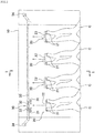
- Reference sign 10 in Figure 1 denotes an apparatus main body, on a front side of which a feeder unit 20 is provided.
- the feeder unit 20 includes: a pair of feeder chucks 21, 21 that grasp corners at both ends of one side of the cloth C; a chuck base 22 to which the feeder chucks 21, 21 are fixed; and a raising-lowering device 23 that raises and lowers the chuck base 22.
- the pair of feeder chucks 21, 21 can be raised and lowered by the raising-lowering device 23.
- the chuck base 22 has a width approximately equivalent to a shoulder width of a person, and the feeder chucks 21, 21 are provided respectively at right and left ends of the chuck base 22.
- Each feeder chuck 21 is composed of two chucks disposed on right and left sides at a predetermined interval.
- the raising-lowering device 23 raises the cloth C along with the feeder chucks 21, 21 and passes the cloth C to a spreading unit 30 to be described later.
- the cloth spreading apparatus A has one or more feeder units 20. In this embodiment, four feeder units 20 are provided, and the cloth C can be fed from any one of the feeder units 20.
- the raising-lowering device 23 is driven by an actuator capable of speed and position control.
- the "actuator capable of speed and position control” include a servo actuator, such as a servomotor or a servo cylinder, and a stepping motor.
- the raising-lowering device 23 in this embodiment is composed of a rod 23a that guides the chuck base 22 so as to move upward and downward, an endless belt 23b that is disposed along the rod 23a and fixed to the chuck base 22, and a servomotor 23c that drives a pulley, wound with the endless belt 23b, to rotate in normal and reverse directions.
- the spreading unit 30 is provided at a position corresponding to an upper part of the raising-lowering device 23.
- the spreading unit 30 includes: a pair of spreading chucks 31, 31 that grasp corners at both ends of one side of the cloth C; a pair of carriages 32, 32 to each of which one spreading chuck 31 is fixed; a rail 33 that guides the carriages 32, 32 so as to move rightward and leftward; and a traversing device 34 that can separately move the carriages 32.
- the traversing device 34 is formed by a combination of a servomotor and an endless belt.
- the traversing device 34 can cause the pair of spreading chucks 31, 31 to traverse separately.
- the traversing device 34 may also be configured to be driven by an actuator capable of speed and position control, other than a servomotor.
- the spreading chucks 31 When the cloth C is raised by the action of the feeder unit 20, the spreading chucks 31 receive the cloth C from the feeder chucks 21 and grasp the corners of the cloth C. In this process, each spreading chuck 31 passes through a clearance between the two chucks composing the feeder chuck 21. Thus, the cloth C can be passed without interference between the spreading chucks 31 and the feeder chucks 21. Thereafter, the pair of spreading chucks 31, 31 traverse rightward and leftward so as to widen the interval therebetween, so that the cloth C can be spread and hung down.
- a passer unit 40 is disposed below the spreading unit 30.
- the passer unit 40 includes a vacuum box 41 as an intermediate movable body that suctions and retains an upper end edge of the cloth C when a negative pressure is exerted, and an air cylinder, a servomotor, or the like (not shown) as an advancing-retracting device that advances and retracts the vacuum box 41.
- an upper surface of the vacuum box 41 has a front part 42 that is slightly inclined toward a front side, and a sunken part 43 that is located on a rear side of and one level lower than the front part 42.
- the vacuum box 41 has a rear-facing surface 44 that is slightly inclined upward (e.g., at about 30 degrees from a vertical direction), between the front part 42 and the sunken part 43, and further has an air cylinder 45 as a clamp driving device, on the upper surface on the rear side of the sunken part 43.
- the air cylinder 45 supports a clamp 46, formed by an elastic body, at a leading end of a piston rod, and can advance and retract the clamp 46 to and from the rear-facing surface 44 by advancing and retracting motions of the piston rod.
- the vacuum box 41 has, at a rear end thereof, a negative-pressure generator 47, such as a blower, that generates a negative pressure inside the vacuum box 41.
- a negative pressure generated by the negative-pressure generator 47 can be exerted on the upper surface through a large number of small holes h provided in the front part 42, the sunken part 43, and the rear-facing surface 44 of the upper surface.
- a primary conveyor 50 formed by a belt conveyor is disposed below the passer unit 40.
- the primary conveyor 50 includes a conveyor belt 51 having a large number of small holes, and a vacuum box 52 disposed below a conveying surface of the conveyor belt 51.
- the primary conveyor 50 can deliver the cloth C toward the rear side while suctioning the cloth C.
- a secondary conveyor 60 formed by a belt conveyor is connected to the rear side of the primary conveyor 50, and the secondary conveyor 60 can deliver the cloth C to a processing device for the next process, for example, a roll ironer.
- An airflow shaping section 11 is formed at a lower part of the front side of the apparatus main body 10.
- a lower part of the airflow shaping section 11 is connected to a blower 13 through a duct 12.
- a second duct 14 is formed behind the airflow shaping section 11.
- the duct 14 is configured to allow communication between the vacuum box 52 of the primary conveyor 50 and the blower 13.
- An opening-closing plate 15 is provided between the ducts 12, 14 and the blower 13. The opening-closing plate 15 alternatively opens and closes an opening of the duct 12 and an opening of the duct 14. Thus, it is possible to alternatively switch between a state where air is suctioned from the front side of the apparatus main body 10 into the airflow shaping section 11 and a state where the vacuum box 52 of the primary conveyor 50 is operated.
- the cloth spreading apparatus A includes a control device 70 that controls the operations of the raising-lowering device 23 and the traversing device 34.
- the control device 70 is a computer composed of a CPU, a memory, and others. It is possible to move the feeder chucks 21 and the spreading chucks 31 in synchronization with each other by controlling the operations of the raising-lowering device 23 and the traversing device 34 by the control device 70. This will be described in detail later.
- the feeder chucks 21 are on standby at a lowered feeding position. A worker finds corners at both ends of one side of the cloth C and has the corners respectively grasped by the feeder chucks 21, 21.
- the feeder chucks 21 are raised to the highest position from the feeding position.
- the cloth C is passed from the feeder chucks 21 to the spreading chucks 31.
- the pair of spreading chucks 31, 31 move rightward and leftward so as to widen the interval therebetween, so that the cloth C is hung down and spread and thus unfolded.
- the opening-closing plate 15 is switched to create a state where air is suctioned into the airflow shaping section 11, so that the cloth C is drawn into the airflow shaping section 11 by a negative pressure.
- the cloth C is moved from the primary conveyor 50 to the secondary conveyor 60, and is discharged to the processing device for the next process.
- the feeder chucks 21 are lowered to the feeding position.
- steps (2) and (3) the feeder chucks 21 and the spreading chucks 31 are moved at the same time.
- "Moved at the same time” does not mean that the motions of these pairs of chucks have to be started and stopped at the same timing, as long as one pair of chucks are moved during a period of motion of the other pair of chucks.
- the cloth spreading apparatus A has four feeder units 20, and the cloth C can be fed from any one of the feeder units 20.
- One spreading unit 30 is provided for these four feeder units 20, and pieces of cloth C fed into the respective feeder units 20 are sequentially processed. Therefore, at the time when a piece of cloth C is fed into one feeder unit 20, the spreading unit 30 may be in the middle of the action of passing or spreading another piece of cloth C having been fed into another feeder unit 20. In this case, the feeder chucks 21 may start to rise first and the spreading chucks 31 may start to traverse after completion of the action of spreading that other cloth C.
- each feeder chuck 21 is composed of two chucks disposed on the right and left sides at a predetermined interval.
- Each spreading chuck 31 passes through the clearance between the two chucks, so that the cloth C can be passed without interference between the spreading chucks 31 and the feeder chucks 21.
- the feeder chucks 21 are moved so as to pass through the passing position d while the spreading chucks 31 are stopped at the passing position d.
- the speeds of the feeder chucks 21 and the spreading chucks 31 may be adjusted such that the spreading chucks 31 arrive at the passing position d earlier, or such that the feeder chucks 21 stop temporarily at a position short of the passing position d.
- the feeder chucks 21 and the spreading chucks 31 are moved at the same time. Also in this case, the motions of the feeder chucks 21 and the spreading chucks 31 do not have to be started and stopped at the same timing, as long as one pair of chucks are moved during a period of motion of the other pair of chucks.
- the spreading chucks 31 start to traverse after the feeder chucks 21 are raised to a position at which the feeder chucks 21 do not interfere with the spreading chucks 31. Since the traversing distance of the spreading chucks 31 is generally longer than the rising distance of the feeder chucks 21, the spreading chucks 31 still traverse after the feeder chucks 21 stop upon reaching the higher position c.
- the cloth spreading apparatus A of this embodiment can spread a washed piece of cloth and carry out this cloth to a roll ironer etc., and the vacuum box 41 can securely retain a received piece of cloth and reliably transfer the cloth onto the primary conveyor 50 at a predetermined position, in such cases as where an especially heavy piece of cloth is to be passed or where especially the operation speed is raised to enhance the efficiency of supplying cloth to a roll ironer.
- the clamp driving device is the air cylinder 45 that advances and retracts the clamp 46 straight to and from the rear-facing surface 44.
- the height of protrusion of the clamp 46 and the air cylinder 45 from the upper surface of the vacuum box 41 can be reduced, and the configuration of the cloth spreading apparatus A can be thereby made compact in the height direction.
- a negative pressure generated by the negative-pressure generator 47 and acting from the inside of the vacuum box 41 on the upper surface is used to retain the upper end portion of the cloth C on the upper surface.
- a received piece of cloth can be retained more firmly and transferred more reliably onto the primary conveyor 50 at a predetermined position.
- the clamp driving device may be a device that advances and retracts the clamp to and from the rear-facing surface by swinging the clamp, instead of a device that advances and retracts the clamp straight to and from the rear-facing surface.
- the rear-facing surface 44 can be set to an arbitrary inclination angle, and may be vertical.
- the cloth spreading apparatus of the present invention can securely retain a received piece of cloth and reliably transfer the cloth onto the belt conveyor at a predetermined position, in cases such as where an especially heavy piece of cloth is to be passed or where especially the operation speed is raised to enhance the efficiency of supplying cloth to an iron roller.
Abstract
Description
- The present invention relates to a cloth spreading apparatus that is used when spreading, one by one, pieces of cloth having been washed at a cloth washing factory etc., to feed the cloth into an iron roller (also called a roll ironer).
- Examples of known conventional cloth spreading apparatuses include the one described in
Patent Literature 1 that has been disclosed before by the present applicant. This cloth spreading apparatus includes: a pair of feeder chucks that grasp adjacent corners of a washed piece of cloth; a raising-lowering device that raises and lowers the pair of feeder chucks; a pair of spreading chucks that receive the cloth from the pair of feeder chucks at a raised position of the feeder chucks and grasp the adjacent corners of the cloth; a traversing device that causes the pair of spreading chucks to traverse; an intermediate movable body on an upper surface of which an upper end portion of the cloth is retained; an advancing-retracting device that advances and retracts the intermediate movable body; and a belt conveyor that carries out the spread cloth. - In this conventional cloth spreading apparatus, the pair of feeder chucks are engaged with adjacent corners of a washed piece of cloth at a lowered position, directly by a worker or through a cloth supply device, and raise the cloth to a traversing position of the spreading chucks. The pair of spreading chucks traverse to positions closer to each other to receive the adjacent corners of the cloth from the feeder chucks, and then traverse to positions farther away from each other to pull the adjacent corners so as to spread the cloth. The intermediate movable body receives, at an advanced position, an upper end portion of the spread cloth from the spreading chucks onto an upper surface of a front part thereof, sucks and retains the upper end portion by a negative pressure, and then stops the negative pressure and releases the upper end portion of the cloth while moving to a retracted position, so as to transfer the cloth onto a front part of the belt conveyor. The belt conveyor carries out the received cloth in a spread state toward an iron roller.
- Patent Literature 1: Japanese Patent Laid-Open No.
2016-033271 - Further research conducted by the present inventor on the above conventional cloth spreading apparatus has found the following problem: since a negative pressure exerted by the intermediate movable body on the upper surface of the front part thereof is used to retain an upper end portion of a piece of cloth, this cloth spreading apparatus has difficulty in securely retaining a received piece of cloth and reliably transferring the cloth onto the belt conveyor at a predetermined position, in such cases as where an especially heavy piece of cloth is to be passed or where especially the operation speed is raised to enhance the efficiency of supplying cloth to an iron roller.
- To solve this problem, the present inventor has considered providing a swinging clamp on an upper surface of a front part of a vacuum box, and opening and closing this vacuum box so as to retain an upper end portion of a piece of cloth by the swinging clamp and a negative pressure exerted by the vacuum box on the upper surface of the front part thereof. While this is effective to some extent, the retention is still not secure enough, so that an upper end portion of a piece of cloth slips while being retained and the cloth cannot be transferred onto the belt conveyor at a predetermined position, thus leaving room for improvement.
- The present invention advantageously solves the problem with the conventional cloth spreading apparatus as described above. A cloth spreading apparatus of the present invention includes: a pair of feeder chucks that grasp adjacent corners of a washed piece of cloth; a raising-lowering device that raises and lowers the pair of feeder chucks; a pair of spreading chucks that receive the cloth from the pair of feeder chucks at a raised position of the feeder chucks and grasp the adjacent corners of the cloth; a traversing device that causes the pair of spreading chucks to traverse; an intermediate movable body on an upper surface of which an upper end portion of the cloth is retained; an advancing-retracting device that advances and retracts the intermediate movable body; and a belt conveyor that carries out the spread cloth.
- In this cloth spreading apparatus, the pair of feeder chucks are engaged with adjacent corners of a washed piece of cloth at a lowered position, and raise the cloth to a traversing position of the spreading chucks; the pair of spreading chucks traverse to positions closer to each other to receive the adjacent corners of the cloth from the feeder chucks, and then traverse to positions farther away from each other to pull the adjacent corners so as to spread the cloth; the intermediate movable body receives, at an advanced position, an upper end portion of the spread cloth from the spreading chucks onto an upper surface and retains the upper end portion, and then releases the upper end portion of the cloth while moving to a retracted position so as to transfer the cloth onto a front part of the belt conveyor; and the belt conveyor carries out the received cloth in a spread state.
- The intermediate movable body has:
- a rear-facing surface that is a part of the upper surface between a front part and a sunken part located at a lower level than the front part, and that extends downward from the front part toward the sunken part;
- a clamp that is placed opposite to the rear-facing surface; and
- a clamp driving device that advances and retracts the clamp to and from the rear-facing surface so as to hold an upper portion of the cloth between the clamp and the rear-facing surface and release the upper portion from therebetween.
- In the cloth spreading apparatus of the present invention, the pair of feeder chucks are engaged with adjacent corners of a washed piece of cloth at the lowered position, and raise this cloth to the traversing position of the spreading chucks. The pair of spreading chucks traverse to positions closer to each other to receive the adjacent corners of the cloth from the feeder chucks, and then traverse to positions farther away from each other to pull the adjacent corners so as to spread the cloth. The intermediate movable body receives, at the advanced position, an upper end portion of the spread cloth from the spreading chucks onto the upper surface and retains the upper end portion, and then releases the upper end portion of the cloth while moving to the retracted position so as to transfer the cloth onto the front part of the belt conveyor. The belt conveyor carries out the received cloth in a spread state.
- For the intermediate movable body to receive, at the advanced position, the upper end portion of the spread cloth from the spreading chucks onto the upper surface and retain the upper end portion, the clamp driving device retracts the clamp in advance so as to be separated from the rear-facing surface, and when the upper end portion of the cloth is laid over the intermediate movable body from the front part to at least the rear-facing surface thereof, the clamp driving device advances the clamp so as to hold the upper end portion of the cloth between the clamp and the rear-facing surface. Here, the front part and the rear-facing surface of the upper surface of the intermediate movable body have different angles. Therefore, the pulling force applied from a portion of the cloth below the upper end portion thereof to the upper end portion changes direction on the rear-facing surface and is reduced by friction at a corner between the front part and the rear-facing surface, so that the upper end portion of the cloth is reliably held between the clamp and the rear-facing surface.
- Thus, the cloth spreading apparatus of the present invention can securely retain a received piece of cloth and reliably transfer the cloth onto the belt conveyor at a predetermined position, in such cases as where an especially heavy piece of cloth is to be passed or where especially the operation speed is raised to enhance the efficiency of supplying cloth to an iron roller.
- In the cloth spreading apparatus of the present invention, the clamp driving device may be a device that advances and retracts the clamp by swinging the clamp to and from the rear-facing surface. However, the clamp driving device is preferably a device that advances and retracts the intermediate movable body straight to and from the rear-facing surface. Thus, the height of protrusion of the clamp and the clamp driving device from the upper surface of the intermediate movable body can be reduced, and the configuration of the cloth spreading apparatus can be thereby made compact in the height direction.
- In the cloth spreading apparatus of the present invention, in addition to the rear-facing surface and the clump, a negative pressure acting from an inside of the intermediate movable body on the upper surface is preferably used to retain the upper end portion of the cloth on the upper surface. Thus, a received piece of cloth can be retained more firmly and transferred more reliably onto the belt conveyor at a predetermined position.
-
-
Figure 1 is a sectional view (a sectional view taken along line I-I ofFigure 2 ) of a cloth spreading apparatus according to an embodiment of the present invention. -
Figure 2 is a front view of the cloth spreading apparatus. -
Figure 3 is a side view showing a vacuum box of the cloth spreading apparatus. -
Figure 4 is an operation chart showing the operation of the vacuum box of the cloth spreading apparatus. -
Figure 5 is an operation chart showing steps (I) and (II) of the cloth spreading apparatus. -
Figure 6 is an operation chart showing steps (III) and (IV) of the cloth spreading apparatus. -
Figure 7 is an operation chart showing steps (V) and (VI) of the cloth spreading apparatus. -
Figure 8 is a detailed operation chart showing steps (1) and (2) of the cloth spreading apparatus. -
Figure 9 is a detailed operation chart showing steps (3) and (4) of the cloth spreading apparatus. -
Figure 10 is a detailed operation chart showing steps (5) and (6) of the cloth spreading apparatus. - An embodiment of the present invention will be described below in detail based on the drawings. First, the basic structure of a cloth spreading apparatus A will be described based on
Figure 1 andFigure 2 . - The cloth spreading apparatus A is an apparatus used to turn a piece of cloth C into a shaped state of being hung down and neatly spread in a quadrangular shape, before being fed into a roll ironer etc. that is a processing device for the next process. The cloth C handled by this apparatus is pieces of cloth that have been washed and dried but have not yet been ironed, and have a quadrangular shape. The term quadrangular shape covers a square shape and a rectangular shape. Examples of such cloth C include sheets, bedding covers, and towels.
-
Reference sign 10 inFigure 1 denotes an apparatus main body, on a front side of which afeeder unit 20 is provided. Thefeeder unit 20 includes: a pair of feeder chucks 21, 21 that grasp corners at both ends of one side of the cloth C; achuck base 22 to which the feeder chucks 21, 21 are fixed; and a raising-loweringdevice 23 that raises and lowers thechuck base 22. The pair of feeder chucks 21, 21 can be raised and lowered by the raising-loweringdevice 23. Thechuck base 22 has a width approximately equivalent to a shoulder width of a person, and the feeder chucks 21, 21 are provided respectively at right and left ends of thechuck base 22. Eachfeeder chuck 21 is composed of two chucks disposed on right and left sides at a predetermined interval. - When a worker manually has a washed and dried piece of cloth C grasped by the feeder chucks 21, 21, the raising-lowering
device 23 raises the cloth C along with the feeder chucks 21, 21 and passes the cloth C to a spreadingunit 30 to be described later. - The cloth spreading apparatus A has one or
more feeder units 20. In this embodiment, fourfeeder units 20 are provided, and the cloth C can be fed from any one of thefeeder units 20. - In this embodiment, the raising-lowering
device 23 is driven by an actuator capable of speed and position control. Examples of the "actuator capable of speed and position control" include a servo actuator, such as a servomotor or a servo cylinder, and a stepping motor. The raising-loweringdevice 23 in this embodiment is composed of arod 23a that guides thechuck base 22 so as to move upward and downward, anendless belt 23b that is disposed along therod 23a and fixed to thechuck base 22, and aservomotor 23c that drives a pulley, wound with theendless belt 23b, to rotate in normal and reverse directions. - The spreading
unit 30 is provided at a position corresponding to an upper part of the raising-loweringdevice 23. The spreadingunit 30 includes: a pair of spreadingchucks carriages chuck 31 is fixed; arail 33 that guides thecarriages traversing device 34 that can separately move thecarriages 32. For example, the traversingdevice 34 is formed by a combination of a servomotor and an endless belt. The traversingdevice 34 can cause the pair of spreadingchucks device 34 may also be configured to be driven by an actuator capable of speed and position control, other than a servomotor. - When the cloth C is raised by the action of the
feeder unit 20, the spreadingchucks 31 receive the cloth C from the feeder chucks 21 and grasp the corners of the cloth C. In this process, each spreadingchuck 31 passes through a clearance between the two chucks composing thefeeder chuck 21. Thus, the cloth C can be passed without interference between the spreadingchucks 31 and the feeder chucks 21. Thereafter, the pair of spreadingchucks - A
passer unit 40 is disposed below the spreadingunit 30. Thepasser unit 40 includes avacuum box 41 as an intermediate movable body that suctions and retains an upper end edge of the cloth C when a negative pressure is exerted, and an air cylinder, a servomotor, or the like (not shown) as an advancing-retracting device that advances and retracts thevacuum box 41. - As shown in
Figure 3 , an upper surface of thevacuum box 41 has afront part 42 that is slightly inclined toward a front side, and asunken part 43 that is located on a rear side of and one level lower than thefront part 42. Thevacuum box 41 has a rear-facingsurface 44 that is slightly inclined upward (e.g., at about 30 degrees from a vertical direction), between thefront part 42 and thesunken part 43, and further has anair cylinder 45 as a clamp driving device, on the upper surface on the rear side of thesunken part 43. Theair cylinder 45 supports aclamp 46, formed by an elastic body, at a leading end of a piston rod, and can advance and retract theclamp 46 to and from the rear-facingsurface 44 by advancing and retracting motions of the piston rod. In addition, thevacuum box 41 has, at a rear end thereof, a negative-pressure generator 47, such as a blower, that generates a negative pressure inside thevacuum box 41. A negative pressure generated by the negative-pressure generator 47 can be exerted on the upper surface through a large number of small holes h provided in thefront part 42, thesunken part 43, and the rear-facingsurface 44 of the upper surface. - A
primary conveyor 50 formed by a belt conveyor is disposed below thepasser unit 40. Theprimary conveyor 50 includes aconveyor belt 51 having a large number of small holes, and avacuum box 52 disposed below a conveying surface of theconveyor belt 51. Theprimary conveyor 50 can deliver the cloth C toward the rear side while suctioning the cloth C. Asecondary conveyor 60 formed by a belt conveyor is connected to the rear side of theprimary conveyor 50, and thesecondary conveyor 60 can deliver the cloth C to a processing device for the next process, for example, a roll ironer. - An
airflow shaping section 11 is formed at a lower part of the front side of the apparatusmain body 10. A lower part of theairflow shaping section 11 is connected to ablower 13 through aduct 12. Asecond duct 14 is formed behind theairflow shaping section 11. Theduct 14 is configured to allow communication between thevacuum box 52 of theprimary conveyor 50 and theblower 13. An opening-closingplate 15 is provided between theducts blower 13. The opening-closingplate 15 alternatively opens and closes an opening of theduct 12 and an opening of theduct 14. Thus, it is possible to alternatively switch between a state where air is suctioned from the front side of the apparatusmain body 10 into theairflow shaping section 11 and a state where thevacuum box 52 of theprimary conveyor 50 is operated. - The cloth spreading apparatus A includes a
control device 70 that controls the operations of the raising-loweringdevice 23 and thetraversing device 34. Thecontrol device 70 is a computer composed of a CPU, a memory, and others. It is possible to move the feeder chucks 21 and the spreadingchucks 31 in synchronization with each other by controlling the operations of the raising-loweringdevice 23 and thetraversing device 34 by thecontrol device 70. This will be described in detail later. - Next, the operation of the cloth spreading apparatus A will be described based on
Figure 4 to Figure 7 . - First, the feeder chucks 21 are on standby at a lowered feeding position. A worker finds corners at both ends of one side of the cloth C and has the corners respectively grasped by the feeder chucks 21, 21.
- Then, the feeder chucks 21 are raised to the highest position from the feeding position. At a passing position on the way at which the feeder chucks 21 coincide with the spreading
chucks 31, the cloth C is passed from the feeder chucks 21 to the spreadingchucks 31. Then, the pair of spreadingchucks - Next, the opening-closing
plate 15 is switched to create a state where air is suctioned into theairflow shaping section 11, so that the cloth C is drawn into theairflow shaping section 11 by a negative pressure. - When the opening-closing
plate 15 is switched again, the airflow inside theairflow shaping section 11 stops, so that the cloth C can be easily pulled up. In this state, as shown inFigure 4 (a) , thevacuum box 41 is advanced into contact with the cloth C and the interval between the spreadingchucks 31 is widened, and at the same time air is blown from the front side, for example. As a result, as shown inFigure 4 (b) , the upper end portion of the cloth C is sucked onto the upper surface of thevacuum box 41 from thefront part 42 to thesunken part 43. Then, as shown inFigure 4 (c) , theclamp 46 is driven to advance by theair cylinder 45, so that the upper end portion of the cloth C is held between theclamp 46 and the rear-facingsurface 44. - Next, as shown in
Figure 4 (d) , an upper portion of the cloth C is pulled onto theprimary conveyor 50 while thevacuum box 41 is retracted. Then, as shown inFigure 4 (e) , theclamp 46 is retracted from the rear-facingsurface 44 by theair cylinder 45 to release the upper end portion of the cloth C, so that the upper end portion of the cloth C makes a transit from thevacuum box 41 to theprimary conveyor 50. During this process, thevacuum box 52 of theprimary conveyor 50 is in operation. - Next, the cloth C is moved from the
primary conveyor 50 to thesecondary conveyor 60, and is discharged to the processing device for the next process. The feeder chucks 21 are lowered to the feeding position. - Next, the unfolding action among the above-described actions in the embodiment will be described in detail based on
Figure 8 to Figure 10 . - (1) First, the feeder chucks 21, 21 are on standby at a lowered feeding position a. Meanwhile, the spreading
chucks chucks 31 are on standby at the same position as the position at which the cloth C has been spread rightward and leftward (the position inFigure 8 (1)) or at a predetermined standby position. The worker finds corners at both ends of one side of the cloth C and has these corners respectively grasped by the feeder chucks 21, 21. - (2) When the cloth C is grasped by the feeder chucks 21, the
control device 70 operates the raising-loweringdevice 23 and thetraversing device 34 at the same time, and thereby raises the feeder chucks 21 from the feeding position a to a passing position d and causes the spreadingchucks 31 to traverse to the passing position d. - (3) When both the feeder chucks 21 and the spreading
chucks 31 arrive at the passing position d, the cloth C having been grasped by the feeder chucks 21 is passed to the spreadingchucks 31. - In steps (2) and (3), the feeder chucks 21 and the spreading
chucks 31 are moved at the same time. "Moved at the same time" here does not mean that the motions of these pairs of chucks have to be started and stopped at the same timing, as long as one pair of chucks are moved during a period of motion of the other pair of chucks. - The cloth spreading apparatus A has four
feeder units 20, and the cloth C can be fed from any one of thefeeder units 20. One spreadingunit 30 is provided for these fourfeeder units 20, and pieces of cloth C fed into therespective feeder units 20 are sequentially processed. Therefore, at the time when a piece of cloth C is fed into onefeeder unit 20, the spreadingunit 30 may be in the middle of the action of passing or spreading another piece of cloth C having been fed into anotherfeeder unit 20. In this case, the feeder chucks 21 may start to rise first and the spreadingchucks 31 may start to traverse after completion of the action of spreading that other cloth C. - In this embodiment, each
feeder chuck 21 is composed of two chucks disposed on the right and left sides at a predetermined interval. Each spreadingchuck 31 passes through the clearance between the two chucks, so that the cloth C can be passed without interference between the spreadingchucks 31 and the feeder chucks 21. To pass the cloth C, therefore, the feeder chucks 21 are moved so as to pass through the passing position d while the spreadingchucks 31 are stopped at the passing position d. This requires the spreadingchucks 31 to arrive at the passing position d earlier than the feeder chucks 21. In this case, the speeds of the feeder chucks 21 and the spreadingchucks 31 may be adjusted such that the spreadingchucks 31 arrive at the passing position d earlier, or such that the feeder chucks 21 stop temporarily at a position short of the passing position d. - (4) After the cloth C is passed, the
control device 70 operates the raising-loweringdevice 23 and thetraversing device 34 at the same time, and thereby raises the feeder chucks 21, 21 from the passing position d to a higher position c and causes the spreadingchucks - (5) The pair of spreading
chucks - (6) After the cloth C is passed from the spreading
chucks 31 to thepasser unit 40, the feeder chucks 21 are lowered from the higher position c to the feeding position a. - Also in steps (4) and (5), the feeder chucks 21 and the spreading
chucks 31 are moved at the same time. Also in this case, the motions of the feeder chucks 21 and the spreadingchucks 31 do not have to be started and stopped at the same timing, as long as one pair of chucks are moved during a period of motion of the other pair of chucks. The spreadingchucks 31 start to traverse after the feeder chucks 21 are raised to a position at which the feeder chucks 21 do not interfere with the spreadingchucks 31. Since the traversing distance of the spreadingchucks 31 is generally longer than the rising distance of the feeder chucks 21, the spreadingchucks 31 still traverse after the feeder chucks 21 stop upon reaching the higher position c. - Thus, the cloth spreading apparatus A of this embodiment can spread a washed piece of cloth and carry out this cloth to a roll ironer etc., and the
vacuum box 41 can securely retain a received piece of cloth and reliably transfer the cloth onto theprimary conveyor 50 at a predetermined position, in such cases as where an especially heavy piece of cloth is to be passed or where especially the operation speed is raised to enhance the efficiency of supplying cloth to a roll ironer. - Moreover, in the cloth spreading apparatus of this embodiment, the clamp driving device is the
air cylinder 45 that advances and retracts theclamp 46 straight to and from the rear-facingsurface 44. Thus, the height of protrusion of theclamp 46 and theair cylinder 45 from the upper surface of thevacuum box 41 can be reduced, and the configuration of the cloth spreading apparatus A can be thereby made compact in the height direction. - Furthermore, in the cloth spreading apparatus of this embodiment, in addition to the rear-facing
surface 44 and theclamp 46, a negative pressure generated by the negative-pressure generator 47 and acting from the inside of thevacuum box 41 on the upper surface is used to retain the upper end portion of the cloth C on the upper surface. Thus, a received piece of cloth can be retained more firmly and transferred more reliably onto theprimary conveyor 50 at a predetermined position. - While the present invention has been described above based on the example shown in the drawings, the invention is not limited to the above example but can be appropriately modified within the scope described in the claims. For example, the clamp driving device may be a device that advances and retracts the clamp to and from the rear-facing surface by swinging the clamp, instead of a device that advances and retracts the clamp straight to and from the rear-facing surface. The rear-facing
surface 44 can be set to an arbitrary inclination angle, and may be vertical. - As has been described above, the cloth spreading apparatus of the present invention can securely retain a received piece of cloth and reliably transfer the cloth onto the belt conveyor at a predetermined position, in cases such as where an especially heavy piece of cloth is to be passed or where especially the operation speed is raised to enhance the efficiency of supplying cloth to an iron roller.
-
- A
- Cloth spreading apparatus
- C
- Cloth
- 10
- Apparatus main body
- 20
- Feeder unit
- 21
- Feeder chuck
- 22
- Chuck base
- 23
- Raising-lowering device
- 23a
- Rod
- 23b
- Endless belt
- 23c
- Servomotor
- 30
- Spreading unit
- 31
- Spreading chuck
- 32
- Carriage
- 33
- Rail
- 34
- Traversing device
- 40
- Passer unit
- 41
- Vacuum box
- 42
- Front part
- 43
- Sunken part
- 44
- Rear-facing surface
- 45
- Air cylinder
- 46
- Clamp
- 47
- Negative-pressure generator
- 50
- Primary conveyor
- 60
- Secondary conveyor
- 70
- Control device
Claims (3)
- A cloth spreading apparatus which comprises: a pair of feeder chucks that grasp adjacent corners of a washed piece of cloth; a raising-lowering device that raises and lowers the pair of feeder chucks; a pair of spreading chucks that receive the cloth from the pair of feeder chucks at a raised position of the feeder chucks and grasp the adjacent corners of the cloth; a traversing device that causes the pair of spreading chucks to traverse; an intermediate movable body on an upper surface of which an upper end portion of the cloth is retained; an advancing-retracting device that advances and retracts the intermediate movable body; and a belt conveyor that carries out the spread cloth, and
in which the pair of feeder chucks are engaged with adjacent corners of a washed piece of cloth at a lowered position, and raise the cloth to a traversing position of the spreading chucks; the pair of spreading chucks traverse to positions closer to each other to receive the adjacent corners of the cloth from the feeder chucks, and then traverse to positions farther away from each other to pull the adjacent corners so as to spread the cloth; the intermediate movable body receives, at an advanced position, an upper end portion of the spread cloth from the spreading chucks onto the upper surface and retains the upper end portion, and then releases the upper end portion of the cloth while moving to a retracted position so as to transfer the cloth onto a front part of the belt conveyor; and the belt conveyor carries out the received cloth in a spread state,
characterized in that the intermediate movable body has:a rear-facing surface that is a part of the upper surface between a front part and a sunken part located at a lower level than the front part, and that extends downward from the front part toward the sunken part;a clamp that is placed opposite to the rear-facing surface; anda clamp driving device that advances and retracts the clamp to and from the rear-facing surface so as to hold an upper portion of the cloth between the clamp and the rear-facing surface and release the upper portion from therebetween. - The cloth spreading apparatus according to claim 1, wherein the clamp driving device advances and retracts the clamp straight to and from the rear-facing surface.
- The cloth spreading apparatus according to claim 1 or 2, wherein, in addition to the rear-facing surface and the clamp, a negative pressure acting from an inside of the intermediate movable body on the upper surface is used to retain the upper end portion of the cloth on the upper surface.
Applications Claiming Priority (2)
| Application Number | Priority Date | Filing Date | Title |
|---|---|---|---|
| JP2016239768A JP6621731B2 (en) | 2016-12-09 | 2016-12-09 | Cloth extension device |
| PCT/JP2017/041613 WO2018105363A1 (en) | 2016-12-09 | 2017-11-20 | Fabric stretching device |
Publications (3)
| Publication Number | Publication Date |
|---|---|
| EP3553215A1 true EP3553215A1 (en) | 2019-10-16 |
| EP3553215A4 EP3553215A4 (en) | 2019-12-25 |
| EP3553215B1 EP3553215B1 (en) | 2022-01-05 |
Family
ID=62492039
Family Applications (1)
| Application Number | Title | Priority Date | Filing Date |
|---|---|---|---|
| EP17878277.7A Active EP3553215B1 (en) | 2016-12-09 | 2017-11-20 | Fabric stretching device |
Country Status (7)
| Country | Link |
|---|---|
| US (1) | US10975517B2 (en) |
| EP (1) | EP3553215B1 (en) |
| JP (1) | JP6621731B2 (en) |
| KR (1) | KR20190075132A (en) |
| CN (1) | CN110023552B (en) |
| DK (1) | DK3553215T3 (en) |
| WO (1) | WO2018105363A1 (en) |
Families Citing this family (6)
| Publication number | Priority date | Publication date | Assignee | Title |
|---|---|---|---|---|
| JP7064841B2 (en) * | 2017-09-27 | 2022-05-11 | 株式会社プレックス | Cloth unfolding device |
| DE102019135659A1 (en) * | 2019-11-28 | 2021-06-02 | Herbert Kannegiesser Gmbh | Method and device for gripping rectangular textile objects and / or for feeding rectangular textile objects to a treatment device |
| JPWO2022180844A1 (en) * | 2021-02-26 | 2022-09-01 | ||
| WO2022208796A1 (en) * | 2021-03-31 | 2022-10-06 | 東都フォルダー工業株式会社 | Cloth-feeding device and cloth-spreading device which has said cloth-feeding device |
| DE102021112392A1 (en) | 2021-05-12 | 2022-11-17 | Herbert Kannegiesser Gmbh | Method for feeding items of laundry to a mangle or the like |
| CN114314155B (en) * | 2022-01-12 | 2023-05-05 | 江苏川岛洗涤机械科技有限公司 | Operation control method for shuttle plate of spreader |
Family Cites Families (14)
| Publication number | Priority date | Publication date | Assignee | Title |
|---|---|---|---|---|
| DE1785548B1 (en) * | 1968-05-18 | 1971-01-21 | Kannegiesser Maschinen | Feeding device for feeding items of laundry to a mangle |
| US3568341A (en) * | 1970-01-29 | 1971-03-09 | Ametek Inc | Feeder with diverging slots |
| US3729846A (en) * | 1970-05-01 | 1973-05-01 | Mc Graw Edison Co | Laundry feeding machine |
| DE3119600C2 (en) * | 1981-05-16 | 1985-02-14 | Herbert Kannegiesser Gmbh + Co, 4973 Vlotho | Device for feeding items of laundry to a mangle |
| CH696668A5 (en) * | 1996-03-08 | 2007-09-14 | Jensen Ag Burgdorf | Method for feeding items of laundry to a processing device, and delivery device. |
| JP4204154B2 (en) * | 1999-11-26 | 2009-01-07 | 株式会社プレックス | Cloth spreading method and cloth spreading machine |
| JP4342714B2 (en) * | 2000-10-12 | 2009-10-14 | 株式会社プレックス | Transfer equipment for sheets of isotropic shape in laundry machine |
| AU2003274132A1 (en) * | 2003-10-10 | 2005-04-27 | Societe Jean Michel | Device and method which are used to load flat articles of clothing into a laundry treatment unit |
| JP4358820B2 (en) * | 2005-12-15 | 2009-11-04 | 洋左右 前嶋 | Cloth input device |
| DK176866B1 (en) * | 2006-05-19 | 2010-02-01 | Jensen Denmark As | Apparatus for loading clothing pieces |
| JP5554200B2 (en) * | 2010-10-08 | 2014-07-23 | 洋左右 前嶋 | Cloth reversing device |
| JP2013215361A (en) * | 2012-04-06 | 2013-10-24 | Plex International Design Co Ltd | Clothing spreading apparatus |
| EP2977505B1 (en) * | 2014-07-24 | 2021-02-17 | Girbau Robotics | Spreading machine comprising an auxiliary device for deposition and feeding of flat clothing articles on a conveyor belt |
| JP6389686B2 (en) | 2014-07-31 | 2018-09-12 | 株式会社プレックス | Cloth deployment device |
-
2016
- 2016-12-09 JP JP2016239768A patent/JP6621731B2/en active Active
-
2017
- 2017-11-20 WO PCT/JP2017/041613 patent/WO2018105363A1/en unknown
- 2017-11-20 DK DK17878277.7T patent/DK3553215T3/en active
- 2017-11-20 EP EP17878277.7A patent/EP3553215B1/en active Active
- 2017-11-20 CN CN201780072890.9A patent/CN110023552B/en active Active
- 2017-11-20 KR KR1020197016367A patent/KR20190075132A/en active IP Right Grant
- 2017-11-20 US US16/466,705 patent/US10975517B2/en active Active
Also Published As
| Publication number | Publication date |
|---|---|
| JP2018095979A (en) | 2018-06-21 |
| JP6621731B2 (en) | 2019-12-18 |
| WO2018105363A1 (en) | 2018-06-14 |
| EP3553215B1 (en) | 2022-01-05 |
| US20190301081A1 (en) | 2019-10-03 |
| CN110023552B (en) | 2021-06-08 |
| EP3553215A4 (en) | 2019-12-25 |
| KR20190075132A (en) | 2019-06-28 |
| CN110023552A (en) | 2019-07-16 |
| DK3553215T3 (en) | 2022-03-28 |
| US10975517B2 (en) | 2021-04-13 |
Similar Documents
| Publication | Publication Date | Title |
|---|---|---|
| EP3553215B1 (en) | Fabric stretching device | |
| US11066769B2 (en) | Cloth spreading apparatus | |
| EP3636824B1 (en) | Cloth spreading apparatus | |
| JP6389686B2 (en) | Cloth deployment device | |
| WO2006057112A1 (en) | Method and device for extending and carrying cloth | |
| JP2007092255A (en) | Method for extending fabric and fabric-extending machine | |
| EP0666360B1 (en) | A method and an apparatus for feeding a laundry article to a laundry processing apparatus | |
| WO2016047024A1 (en) | Square fabric spreading apparatus | |
| CN111936688B (en) | Edge holding device and cloth automatic unfolding machine with same | |
| JP5111224B2 (en) | Cloth stretcher conveyor | |
| WO2021256541A1 (en) | Cloth stretching device | |
| WO2018143128A1 (en) | Cloth stretching apparatus | |
| JP5329117B2 (en) | Cloth spreading and conveying method and cloth spreading and conveying machine | |
| EP1198634B1 (en) | A method and an apparatus for introducing substantially rectangular pieces of laundry into a laundry treatment apparatus | |
| CN111051592A (en) | Automatic cloth unfolding machine | |
| JP7018326B2 (en) | Cloth unfolding device |
Legal Events
| Date | Code | Title | Description |
|---|---|---|---|
| STAA | Information on the status of an ep patent application or granted ep patent |
Free format text: STATUS: THE INTERNATIONAL PUBLICATION HAS BEEN MADE |
|
| PUAI | Public reference made under article 153(3) epc to a published international application that has entered the european phase |
Free format text: ORIGINAL CODE: 0009012 |
|
| STAA | Information on the status of an ep patent application or granted ep patent |
Free format text: STATUS: REQUEST FOR EXAMINATION WAS MADE |
|
| 17P | Request for examination filed |
Effective date: 20190603 |
|
| AK | Designated contracting states |
Kind code of ref document: A1 Designated state(s): AL AT BE BG CH CY CZ DE DK EE ES FI FR GB GR HR HU IE IS IT LI LT LU LV MC MK MT NL NO PL PT RO RS SE SI SK SM TR |
|
| AX | Request for extension of the european patent |
Extension state: BA ME |
|
| REG | Reference to a national code |
Ref country code: DE Ref legal event code: R079 Ref document number: 602017052101 Country of ref document: DE Free format text: PREVIOUS MAIN CLASS: D06C0003000000 Ipc: D06F0067040000 |
|
| A4 | Supplementary search report drawn up and despatched |
Effective date: 20191122 |
|
| RIC1 | Information provided on ipc code assigned before grant |
Ipc: D06F 67/04 20060101AFI20191118BHEP Ipc: D06C 3/00 20060101ALI20191118BHEP |
|
| DAV | Request for validation of the european patent (deleted) | ||
| DAX | Request for extension of the european patent (deleted) | ||
| GRAP | Despatch of communication of intention to grant a patent |
Free format text: ORIGINAL CODE: EPIDOSNIGR1 |
|
| STAA | Information on the status of an ep patent application or granted ep patent |
Free format text: STATUS: GRANT OF PATENT IS INTENDED |
|
| INTG | Intention to grant announced |
Effective date: 20210819 |
|
| GRAS | Grant fee paid |
Free format text: ORIGINAL CODE: EPIDOSNIGR3 |
|
| GRAA | (expected) grant |
Free format text: ORIGINAL CODE: 0009210 |
|
| STAA | Information on the status of an ep patent application or granted ep patent |
Free format text: STATUS: THE PATENT HAS BEEN GRANTED |
|
| AK | Designated contracting states |
Kind code of ref document: B1 Designated state(s): AL AT BE BG CH CY CZ DE DK EE ES FI FR GB GR HR HU IE IS IT LI LT LU LV MC MK MT NL NO PL PT RO RS SE SI SK SM TR |
|
| REG | Reference to a national code |
Ref country code: GB Ref legal event code: FG4D |
|
| REG | Reference to a national code |
Ref country code: CH Ref legal event code: EP |
|
| REG | Reference to a national code |
Ref country code: AT Ref legal event code: REF Ref document number: 1460709 Country of ref document: AT Kind code of ref document: T Effective date: 20220115 |
|
| REG | Reference to a national code |
Ref country code: DE Ref legal event code: R096 Ref document number: 602017052101 Country of ref document: DE |
|
| REG | Reference to a national code |
Ref country code: IE Ref legal event code: FG4D |
|
| REG | Reference to a national code |
Ref country code: DK Ref legal event code: T3 Effective date: 20220321 |
|
| REG | Reference to a national code |
Ref country code: LT Ref legal event code: MG9D |
|
| REG | Reference to a national code |
Ref country code: NL Ref legal event code: MP Effective date: 20220105 |
|
| REG | Reference to a national code |
Ref country code: AT Ref legal event code: MK05 Ref document number: 1460709 Country of ref document: AT Kind code of ref document: T Effective date: 20220105 |
|
| PG25 | Lapsed in a contracting state [announced via postgrant information from national office to epo] |
Ref country code: NL Free format text: LAPSE BECAUSE OF FAILURE TO SUBMIT A TRANSLATION OF THE DESCRIPTION OR TO PAY THE FEE WITHIN THE PRESCRIBED TIME-LIMIT Effective date: 20220105 |
|
| PG25 | Lapsed in a contracting state [announced via postgrant information from national office to epo] |
Ref country code: SE Free format text: LAPSE BECAUSE OF FAILURE TO SUBMIT A TRANSLATION OF THE DESCRIPTION OR TO PAY THE FEE WITHIN THE PRESCRIBED TIME-LIMIT Effective date: 20220105 Ref country code: RS Free format text: LAPSE BECAUSE OF FAILURE TO SUBMIT A TRANSLATION OF THE DESCRIPTION OR TO PAY THE FEE WITHIN THE PRESCRIBED TIME-LIMIT Effective date: 20220105 Ref country code: PT Free format text: LAPSE BECAUSE OF FAILURE TO SUBMIT A TRANSLATION OF THE DESCRIPTION OR TO PAY THE FEE WITHIN THE PRESCRIBED TIME-LIMIT Effective date: 20220505 Ref country code: NO Free format text: LAPSE BECAUSE OF FAILURE TO SUBMIT A TRANSLATION OF THE DESCRIPTION OR TO PAY THE FEE WITHIN THE PRESCRIBED TIME-LIMIT Effective date: 20220405 Ref country code: LT Free format text: LAPSE BECAUSE OF FAILURE TO SUBMIT A TRANSLATION OF THE DESCRIPTION OR TO PAY THE FEE WITHIN THE PRESCRIBED TIME-LIMIT Effective date: 20220105 Ref country code: HR Free format text: LAPSE BECAUSE OF FAILURE TO SUBMIT A TRANSLATION OF THE DESCRIPTION OR TO PAY THE FEE WITHIN THE PRESCRIBED TIME-LIMIT Effective date: 20220105 Ref country code: ES Free format text: LAPSE BECAUSE OF FAILURE TO SUBMIT A TRANSLATION OF THE DESCRIPTION OR TO PAY THE FEE WITHIN THE PRESCRIBED TIME-LIMIT Effective date: 20220105 Ref country code: BG Free format text: LAPSE BECAUSE OF FAILURE TO SUBMIT A TRANSLATION OF THE DESCRIPTION OR TO PAY THE FEE WITHIN THE PRESCRIBED TIME-LIMIT Effective date: 20220405 |
|
| PG25 | Lapsed in a contracting state [announced via postgrant information from national office to epo] |
Ref country code: PL Free format text: LAPSE BECAUSE OF FAILURE TO SUBMIT A TRANSLATION OF THE DESCRIPTION OR TO PAY THE FEE WITHIN THE PRESCRIBED TIME-LIMIT Effective date: 20220105 Ref country code: LV Free format text: LAPSE BECAUSE OF FAILURE TO SUBMIT A TRANSLATION OF THE DESCRIPTION OR TO PAY THE FEE WITHIN THE PRESCRIBED TIME-LIMIT Effective date: 20220105 Ref country code: GR Free format text: LAPSE BECAUSE OF FAILURE TO SUBMIT A TRANSLATION OF THE DESCRIPTION OR TO PAY THE FEE WITHIN THE PRESCRIBED TIME-LIMIT Effective date: 20220406 Ref country code: FI Free format text: LAPSE BECAUSE OF FAILURE TO SUBMIT A TRANSLATION OF THE DESCRIPTION OR TO PAY THE FEE WITHIN THE PRESCRIBED TIME-LIMIT Effective date: 20220105 Ref country code: AT Free format text: LAPSE BECAUSE OF FAILURE TO SUBMIT A TRANSLATION OF THE DESCRIPTION OR TO PAY THE FEE WITHIN THE PRESCRIBED TIME-LIMIT Effective date: 20220105 |
|
| PG25 | Lapsed in a contracting state [announced via postgrant information from national office to epo] |
Ref country code: IS Free format text: LAPSE BECAUSE OF FAILURE TO SUBMIT A TRANSLATION OF THE DESCRIPTION OR TO PAY THE FEE WITHIN THE PRESCRIBED TIME-LIMIT Effective date: 20220505 |
|
| REG | Reference to a national code |
Ref country code: DE Ref legal event code: R097 Ref document number: 602017052101 Country of ref document: DE |
|
| PG25 | Lapsed in a contracting state [announced via postgrant information from national office to epo] |
Ref country code: SM Free format text: LAPSE BECAUSE OF FAILURE TO SUBMIT A TRANSLATION OF THE DESCRIPTION OR TO PAY THE FEE WITHIN THE PRESCRIBED TIME-LIMIT Effective date: 20220105 Ref country code: SK Free format text: LAPSE BECAUSE OF FAILURE TO SUBMIT A TRANSLATION OF THE DESCRIPTION OR TO PAY THE FEE WITHIN THE PRESCRIBED TIME-LIMIT Effective date: 20220105 Ref country code: RO Free format text: LAPSE BECAUSE OF FAILURE TO SUBMIT A TRANSLATION OF THE DESCRIPTION OR TO PAY THE FEE WITHIN THE PRESCRIBED TIME-LIMIT Effective date: 20220105 Ref country code: EE Free format text: LAPSE BECAUSE OF FAILURE TO SUBMIT A TRANSLATION OF THE DESCRIPTION OR TO PAY THE FEE WITHIN THE PRESCRIBED TIME-LIMIT Effective date: 20220105 Ref country code: CZ Free format text: LAPSE BECAUSE OF FAILURE TO SUBMIT A TRANSLATION OF THE DESCRIPTION OR TO PAY THE FEE WITHIN THE PRESCRIBED TIME-LIMIT Effective date: 20220105 |
|
| PLBE | No opposition filed within time limit |
Free format text: ORIGINAL CODE: 0009261 |
|
| STAA | Information on the status of an ep patent application or granted ep patent |
Free format text: STATUS: NO OPPOSITION FILED WITHIN TIME LIMIT |
|
| PG25 | Lapsed in a contracting state [announced via postgrant information from national office to epo] |
Ref country code: AL Free format text: LAPSE BECAUSE OF FAILURE TO SUBMIT A TRANSLATION OF THE DESCRIPTION OR TO PAY THE FEE WITHIN THE PRESCRIBED TIME-LIMIT Effective date: 20220105 |
|
| 26N | No opposition filed |
Effective date: 20221006 |
|
| PG25 | Lapsed in a contracting state [announced via postgrant information from national office to epo] |
Ref country code: SI Free format text: LAPSE BECAUSE OF FAILURE TO SUBMIT A TRANSLATION OF THE DESCRIPTION OR TO PAY THE FEE WITHIN THE PRESCRIBED TIME-LIMIT Effective date: 20220105 |
|
| PG25 | Lapsed in a contracting state [announced via postgrant information from national office to epo] |
Ref country code: MC Free format text: LAPSE BECAUSE OF FAILURE TO SUBMIT A TRANSLATION OF THE DESCRIPTION OR TO PAY THE FEE WITHIN THE PRESCRIBED TIME-LIMIT Effective date: 20220105 |
|
| REG | Reference to a national code |
Ref country code: CH Ref legal event code: PL |
|
| GBPC | Gb: european patent ceased through non-payment of renewal fee |
Effective date: 20221120 |
|
| REG | Reference to a national code |
Ref country code: BE Ref legal event code: MM Effective date: 20221130 |
|
| PG25 | Lapsed in a contracting state [announced via postgrant information from national office to epo] |
Ref country code: LI Free format text: LAPSE BECAUSE OF NON-PAYMENT OF DUE FEES Effective date: 20221130 Ref country code: IT Free format text: LAPSE BECAUSE OF FAILURE TO SUBMIT A TRANSLATION OF THE DESCRIPTION OR TO PAY THE FEE WITHIN THE PRESCRIBED TIME-LIMIT Effective date: 20220105 Ref country code: CH Free format text: LAPSE BECAUSE OF NON-PAYMENT OF DUE FEES Effective date: 20221130 |
|
| PG25 | Lapsed in a contracting state [announced via postgrant information from national office to epo] |
Ref country code: LU Free format text: LAPSE BECAUSE OF NON-PAYMENT OF DUE FEES Effective date: 20221120 |
|
| PG25 | Lapsed in a contracting state [announced via postgrant information from national office to epo] |
Ref country code: IE Free format text: LAPSE BECAUSE OF NON-PAYMENT OF DUE FEES Effective date: 20221120 Ref country code: GB Free format text: LAPSE BECAUSE OF NON-PAYMENT OF DUE FEES Effective date: 20221120 |
|
| PG25 | Lapsed in a contracting state [announced via postgrant information from national office to epo] |
Ref country code: FR Free format text: LAPSE BECAUSE OF NON-PAYMENT OF DUE FEES Effective date: 20221130 Ref country code: BE Free format text: LAPSE BECAUSE OF NON-PAYMENT OF DUE FEES Effective date: 20221130 |
|
| PGFP | Annual fee paid to national office [announced via postgrant information from national office to epo] |
Ref country code: DK Payment date: 20231122 Year of fee payment: 7 Ref country code: DE Payment date: 20231129 Year of fee payment: 7 |
|
| PG25 | Lapsed in a contracting state [announced via postgrant information from national office to epo] |
Ref country code: HU Free format text: LAPSE BECAUSE OF FAILURE TO SUBMIT A TRANSLATION OF THE DESCRIPTION OR TO PAY THE FEE WITHIN THE PRESCRIBED TIME-LIMIT; INVALID AB INITIO Effective date: 20171120 |